

DFI P4M266A-MLV User Manual

P4M266A-MLV
Rev. AA+
System Board
User’s Manual
79910409

Copyright
This publication contains information that is protected by copyright.
No part of it may be reproduced in any form or by any means or
used to make any transformation/adaptation without the prior
written permission from the copyright holders.
This publication is provided for informational purposes only. The
manufacturer makes no representations or warranties with respect to
the contents or use of this manual and specifically disclaims any
express or implied warranties of merchantability or fitness for any
particular purpose. The user will assume the entire risk of the use or
the results of the use of this document. Further, the manufacturer
reserves the right to revise this publication and make changes to its
contents at any time, without obligation to notify any person or
entity of such revisions or changes.
© 2004. All Rights Reserved.
Trademarks
Windows® 98, Windows® 98 SE, Windows® ME, Windows® 2000,
Windows NT® 4.0 and Windows® XP are registered trademarks of
Microsoft Corporation. Intel® and Pentium® 4 are registered
trademarks of Intel Corporation. VIA is a registered trademark of
VIA Technologies, Inc. Award is a registered trademark of Award
Software, Inc. Other trademarks and registered trademarks of
products appearing in this manual are the properties of their
respective holders.
Caution
To avoid damage to the system:
• Use the correct AC input voltage range
..
..
.
To reduce the risk of electric shock:
• Unplug the power cord before removing the system chassis
cover for installation or servicing. After installation or servicing,
cover the system chassis before plugging the power cord.

Battery:
• Danger of explosion if battery incorrectly replaced.
• Replace only with the same or equivalent type recommend
by
the manufacturer.
• Dispose of used batteries according to the battery
manufacturer’s
instructions.
Joystick or MIDI port:
• Do not use any joystick or MIDI device that requires more than
10A current at 5V DC. There is a risk of fire for devices that
exceed this limit.
FCC and DOC Statement on Class B
This equipment has been tested and found to comply with the limits
for a Class B digital device, pursuant to Part 15 of the FCC rules.
These limits are designed to provide reasonable protection against
harmful interference when the equipment is operated in a residential
installation. This equipment generates, uses and can radiate radio
frequency energy and, if not installed and used in accordance with
the instruction manual, may cause harmful interference to radio
communications. However, there is no guarantee that interference
will not occur in a particular installation. If this equipment does cause
harmful interference to radio or television reception, which can be
determined by turning the equipment off and on, the user is
encouraged to try to correct the interference by one or more of the
following measures:
• Reorient or relocate the receiving antenna.
• Increase the separation between the equipment and the receiver.
• Connect the equipment into an outlet on a circuit different from
that to which the receiver is connected.
• Consult the dealer or an experienced radio TV technician for
help.
Notice:
1. The changes or modifications not expressly approved by the
party responsible for compliance could void the user's authority
to operate the equipment.
2. Shielded interface cables must be used in order to comply with
the emission limits.

Notice
This user’s manual contains detailed information about the system
board. If, in some cases, some information doesn’t match those
shown in the multilingual manual, the multilingual manual should
always be regarded as the most updated version. The multilingual
manual is included in the system board package.
To view the user’s manual, insert the CD into a CD-ROM drive. The
autorun screen (Mainboard Utility CD) will appear. Click the
“TOOLS” icon then click “Manual” on the main menu.

Table of Contents
Chapter 1 - Introduction
1.1 Features and Specifications..................................................................................
1.2 Hyper-Threading Technology Functionality Requirements..........
1.3 Package Checklist.........................................................................................................
Chapter 2 - Hardware Installation
2.1 System Board Layout ...........................................................................................
2.2 System Memory...........................................................................................................
2.3 CPU........................................................................................................................................
2.4 Jumper Settings.............................................................................................................
2.5 Rear Panel I/O Ports..............................................................................................
2.6 I/O Connectors...........................................................................................................
Chapter 3 - Award BIOS Setup Utility
3.1 The Basic Input/Output System.....................................................................
3.2 Updating the BIOS.....................................................................................................
Chapter 4 - Supported Softwares
4.1 Desktop Management Interface.................................................................
4.2 Drivers, Utilities and Software Applications.....................................
4.3 Installation Notes......................................................................................................
7
14
15
49
91
16
17
19
24
28
39
93
96
105

Introduction
1
6
113
113
Appendix A - Enabling the Hyper-Threading
Technology
A.1 Enabling the Hyper-Threading Technology...........................................
Appendix B - Using the Suspend to RAM
Function
B.1 Using the Suspend to RAM Function...................................................
Appendix C - System Error Messages
C.1 POST Beep....................................................................................................................
C.2 Error Messages...........................................................................................................
Appendix D - Troubleshooting
D.1 Troubleshooting Checklist.................................................................................
109
115
106

1
Introduction
7
1.1 Features and Specifications
1.1.1 Features
Chipset
• VIA® chipset
- North bridge: VIA® P4M266A
- South bridge: VIA® VT8235CD
Processor
The system board is equipped with Socket 478 for installing one of
the following supported processors.
• Intel® Pentium® 4 (Processor and Northwood) processor up to
3.06GHz
- Intel Hyper-Threading Technology
- FSB: 400MHz and 533MHz
• Intel® Celeron processor
- 400MHz system data bus
System Memory
• Two 184-pin DDR DIMM sockets
• Supports up to 2GB using PC1600 (DDR200) and PC2100
(DDR266) unbuffered DDR SDRAM DIMM, 2.5V type
• Uses x8/x16 512MB technology
Chapter 1 - Introduction
DIMMs
2MBx64
4MBx64
8MBx64
Memory Size
16MB
32MB
64MB
DIMMs
16MBx64
32MBx64
64MBx64
Memory Size
128MB
256MB
512MB

Introduction
1
8
Expansion Slots
• 1 AGP slot
• 3 PCI slots
AGP (Accelerated Graphics Port)
AGP is an interface designed to support high performance 3D
graphics cards. It utilizes a dedicated pipeline to access system
memory for texturing, z-buffering and alpha blending. The universal
AGP slot supports AGP 4x with up to 1066MB/sec. bandwidth for
3D graphics applications. AGP in this system board will deliver faster
and better graphics to your PC.
Onboard Graphics Features
• Full featured Accelerated Graphics Port (AGP) controller
- AGP specification v2.0 compliant
- Graphics Address Relocation Table (GART)
• High resolution CRT RGB interface
- 250MHz RAMDAC on chip with Gamma correction
- Horizontal/vertical sync outputs compliant with Monitor Power
Management protocols
• Integrated Savage8 2D/3D graphics controller and video
accelerator
- Optimized Shared Memory Architecture (SMA)
- 8/16/32MB frame buffer using system memory
- Single cycle 128-bit 3D architecture
- 8M triangles/second setup engine
- 140M pixels/second tri-linear fill rate
- Next generation 128-bit 2D graphics engine
- High quality DVD video playback
- 2D/3D resolutions up to 1920x1440
• 3D rendering features
- MPEG-2 video textures
• 2D hardware acceleration features
• Motion video architecture
• Full software support

1
Introduction
9
Onboard Audio Features
• Supports Microsoft® DirectSound/DirectSound 3D
• AC’97 supported with full duplex, independent sample rate
converter for audio recording and playback
• S/PDIF-in/out compressed digital output
• 6-channel audio output via software
S/PDIF
S/PDIF is a standard audio file transfer format that transfers digital
audio signals to a device without having to be converted first to an
analog format. This prevents the quality of the audio signal from
degrading whenever it is converted to analog. S/PDIF is usually
found on digital audio equipment such as a DAT machine or audio
processing device. The S/PDIF connector on the system board sends
surround sound and 3D audio signal outputs to amplifiers and
speakers and to digital recording devices like CD recorders.
6-channel Audio
The audio jacks at the rear panel will support 6-channel audio only
when the audio utility is configured to support this function. The micin at the rear will be disabled. Use the front audio’s mic-in jack.
Onboard LAN Features
• Integrated LAN controller
• Integrated IEEE 802.3, 10BASE-T and 100BASE-TX compatible
PHY
• 32-bit PCI master interface
• Integrated power management functions
• Full duplex support at both 10 and 100 Mbps
• Supports IEEE 802.3u auto-negotiation
• Supports wire for management

Introduction
1
10
PCI Bus Master IDE Controller
• Two PCI IDE interfaces support up to four IDE devices
• Supports ATA/33, ATA/66, ATA/100 and ATA/133 hard drives
• UDMA Modes 3, 4, 5 and 6 Enhanced IDE (data transfer rate
up to 133MB/sec.)
• Bus mastering reduces CPU utilization during disk transfer
• Supports ATAPI CD-ROM, LS-120 and ZIP
IrDA Interface
The system board is equipped with an IrDA connector for wireless
connectivity between your computer and peripheral devices. The
IRDA (Infrared Data Association) specification supports data
transfers of 115K baud at a distance of 1 meter.
USB Ports
The system board supports USB 2.0 and USB 1.1. USB 1.1
supports 12Mb/second bandwidth while USB 2.0 supports 480Mb/
second bandwidth providing a marked improvement in device transfer speeds between your computer and a wide range of simultaneously accessible external Plug and Play peripherals.
BIOS
• Award BIOS, Windows® 98/2000/ME/XP Plug and Play
compatible
• Supports SCSI sequential boot-up
• Supports DMI 2.0 function
• 4Mbit flash memory
Desktop Management Interface (DMI)
The system board comes with a DMI 2.0 built into the BIOS. The
DMI utility in the BIOS automatically records various information
about your system configuration and stores these information in the
DMI pool, which is a part of the system board's Plug and Play
BIOS. DMI, along with the appropriately networked software, is
designed to make inventory, maintenance and troubleshooting of
computer systems easier. Refer to chapter 4 for instructions on using
the DMI utility.

1
Introduction
11
Rear Panel I/O Ports
• One mini-DIN-6 PS/2 mouse port
• One mini-DIN-6 PS/2 keyboard port
• One RJ45 LAN port
• Two USB 2.0/1.1 ports
• One DB-9 serial port
• One DB-15 VGA port
• One DB-25 parallel port
• One game/MIDI port
• Three audio jacks: line-out, line-in and mic-in
I/O Connectors
• One connector for 2 additional external USB 2.0/1.1 ports
• One connector for 1 external serial port
• One front audio connector for external line-out and mic-in jacks
• Two internal audio connectors (AUX-in and CD-in)
• One S/PDIF-in/out connector
• One connector for IrDA interface
• Two IDE connectors
• One floppy connector
• Two ATX power supply connectors
• Two fan connectors
1.1.2 Intelligence
Dual Function Power Button
Depending on the setting in the “Soft-Off By PWRBTN” field of the
Power Management Setup, this switch will allow the system to enter
the Soft-Off or Suspend mode.

Introduction
1
12
Wake-On-Ring
This feature allows the system that is in the Suspend mode or Soft
Power Off mode to wake-up/power-on to respond to calls coming
from an external modem or respond to calls from a modem PCI
card that uses the PCI PME (Power Management Event) signal to
remotely wake up the PC.
Important:
If you are using a modem add-in card, the 5VSB power source
of your power supply must support ≥720mA.
Wake-On-LAN
This feature allows the network to remotely wake up a Soft Power
Down (Soft-Off) PC. It is supported via the onboard LAN port
and a PCI LAN card that uses the PCI PME (Power Management
Event) signal. However, if your system is in the Suspend mode, you
can power-on the system only through an IRQ or DMA interrupt.
Important:
The 5VSB power source of your power supply must support
≥
720mA.
Wake-On-PS/2 Keyboard
This function allows you to use the PS/2 keyboard to wake up the
system from the S5 state.
Important:
The 5VSB power source of your power supply must support
≥
720mA.

1
Introduction
13
Wake-On-USB Keyboard/Mouse
This function allows you to use a USB keyboard or USB mouse to
wake up a system from the S3 (STR - Suspend To RAM) state.
Important:
• If you are using the Wake-On-USB Keyboard/Mouse
function for 2 USB ports, the 5VSB power source of your
power supply must support ≥1.5A.
• If you are using the Wake-On-USB Keyboard/Mouse function for 3 or more USB ports, the 5VSB power source of
your power supply must support ≥2A.
RTC Timer to Power-on the System
The RTC installed on the system board allows your system to automatically power-on on the set date and time.
ACPI STR
The system board is designed to meet the ACPI (Advanced Configuration and Power Interface) specification. ACPI has energy saving
features that enables PCs to implement Power Management and
Plug-and-Play with operating systems that support OS Direct Power
Management. Currently, only Windows
®®
®®
®
98/2000/ME/XP supports
the ACPI function. ACPI when enabled in the Power Management
Setup will allow you to use the Suspend to RAM function.
With the Suspend to RAM function enabled, you can power-off the
system at once by pressing the power button or selecting “Standby”
when you shut down Windows
®®
®®
®
98/2000/ME/XP without having to
go through the sometimes tiresome process of closing files,
applications and operating system. This is because the system is
capable of storing all programs and data files during the entire
operating session into RAM (Random Access Memory) when it
powers-off. The operating session will resume exactly where you left
off the next time you power-on the system.
Important:
The 5VSB power source of your power supply must support
≥
1A.

Introduction
1
14
AC Power Failure Recovery
When power returns after an AC power failure, you may choose to
either power-on the system manually, let the system power-on
automatically or return to the state where you left off before power
failure occurs.
Virus Protection
Most viruses today destroy data stored in hard drives. The system
board is designed to protect the boot sector and partition table of
your hard disk drive.
1.2 Hyper-Threading Technology Functionality
Requirements
Enabling the functionality of Hyper-Threading Technology for your
computer system requires ALL of the following platforms.
Components:
• CPU - an Intel® Pentium® 4 Processor with HT Technology
• Chipset - an Intel® chipset that supports HT Technology
• BIOS - a BIOS that supports HT Technology and has it enabled
• OS - an operating system that includes optimizations for HT
Technology
Refer to Appendix A for information about enabling the functionality
of the Hyper-Threading Technology. For more information on HyperThreading Technology, go to: www.intel.com/info/hyperthreading.

1
Introduction
15
1.3 Package Checklist
The system board package contains the following items:
! The system board
! A user’s manual
! One IDE cable for ATA/33/66/100/133 IDE drives
! One 34-pin floppy disk drive cable
! One “Mainboard Utility” CD
If any of these items are missing or damaged, please contact your
dealer or sales representative for assistance.
2
16
Hardware Installation
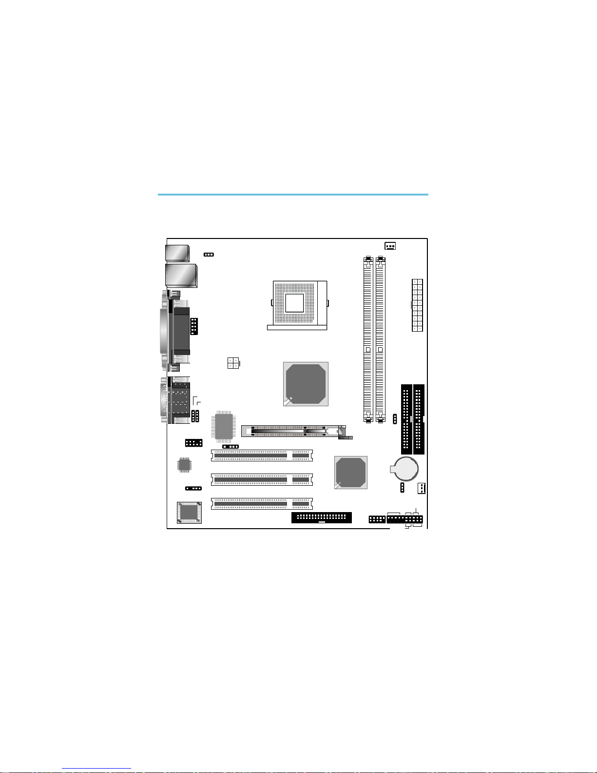
2.1 System Board Layout
Chapter 2 - Hardware Installation
COM 1
VGA
PS/2 power select (JP2)
AUX-in
CD-in
Clear CMOS
(JP1)
Chassis fan
DDR 1
DDR 2
ATX po we r
CPU fan
IDE 1
IDE 2
KB/Mouse
1
LAN, USB 1-2
Parallel
1
COM 2
Socket 478
1
+12V power
Game
Line-out
Line-in
Mic-in
1 1
1
Front audio
Audio
Codec
I/O
chip
1
IrDA
AGP
PCI 1
PCI 2
PCI 3
BIOS
1
S/PDIF
1
FDD
1
USB 3-4
1
HD-LED
RESET
SPEAKER
PWR-LED
ATX-SW
1
1
Battery
VIA
VT8235CD
1
CPU FSB
select (J22)
1
VIA
P4M266A
1
1
2
Hardware Installation
17
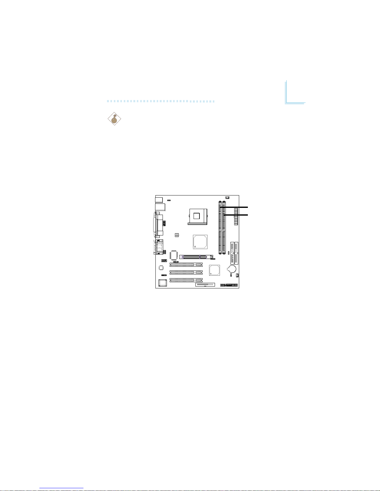
2.2 System Memory
Warning:
Electrostatic discharge (ESD) can damage your system board, processor, disk drives, add-in boards, and other components. Perform the
upgrade instruction procedures described at an ESD workstation only.
If such a station is not available, you can provide some ESD protection
by wearing an antistatic wrist strap and attaching it to a metal part
of the system chassis. If a wrist strap is unavailable, establish and
maintain contact with the system chassis throughout any procedures
requiring ESD protection.
The system board is equipped with two 184-pin DDR DIMM
sockets. DDR (Double Data Rate) is a type of SDRAM that doubles the data rate through reading and writing at both the rising
and falling edge of each clock. This effectively doubles the speed
of operation therefore providing two times faster data transfer.
Refer to chapter 1 (System Memory section) for detailed specification of the memory supported by the system board.
.
.
.
.
.
.
.
.
DDR 1
DDR 2
2
18
Hardware Installation
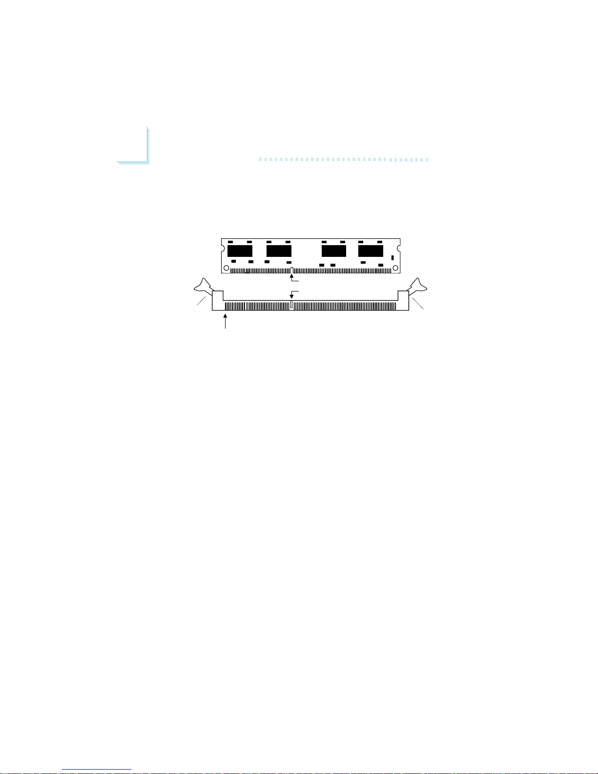
2.2.1 Installing the DIM Module
A DIM module simply snaps into a DIMM socket on the system
board. Pin 1 of the DIM module must correspond with Pin 1 of
the socket.
1. Pull the “tabs” which are at the ends of the socket to the
side.
2. Position the DIMM above the socket with the “notch” in the
module aligned with the “key” on the socket.
3. Seat the module vertically into the socket. Make sure it is
completely seated. The tabs will hold the DIMM in place.
Pin 1
Notch
Key
Tab
Tab
2
Hardware Installation
19
2.3 CPU
2.3.1 Overview
The system board is equipped with a surface mount 478-pin CPU
socket. This socket is exclusively designed for installing an Intel
processor.
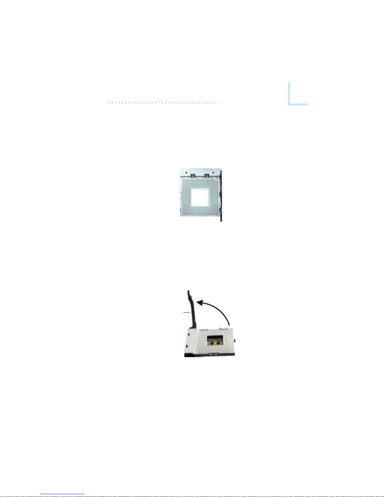
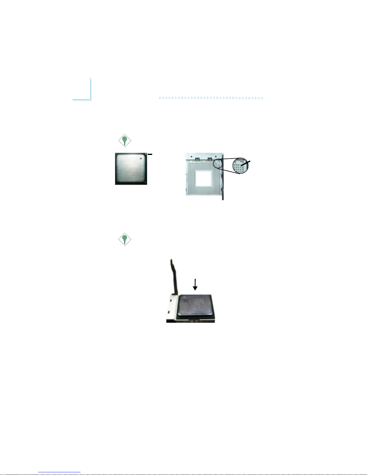
2.3.2 Installing the CPU
1. Locate Socket 478 on the system board.
2. Unlock the socket by pushing the lever sideways, away from the
socket, then lifting it up to a 90o angle. Make sure the socket is
lifted to at least this angle otherwise the CPU will not fit in
properly.
Lever
2
20
Hardware Installation
3. Position the CPU above the socket then align the gold mark
on the corner of the CPU (designated as pin 1) with pin 1 of
the socket.
Important:
Handle the CPU by its edges and avoid touching the pins.
Gold mark
4. Insert the CPU into the socket until it is seated in place. The
CPU will fit in only one orientation and can easily be inserted
without exerting any force.
Important:
Do not force the CPU into the socket. Forcing the CPU into
the socket may bend the pins and damage the CPU.
Pin 1

2
Hardware Installation
21
5. Once the CPU is in place, push down the lever to lock the
socket. The lever should click on the side tab to indicate that
the CPU is completely secured in the socket.
2.3.3 Installing the Fan and Heat Sink
The CPU must be kept cool by using a CPU fan with heatsink.
Without sufficient air circulation across the CPU and heat sink,
the CPU will overheat damaging both the CPU and system board.
Note:
• Only use Intel® certified fan and heat sink.
• An Intel® boxed processor package contains a retention
mechanism, heat sink, fan and installation guide. If the installation procedure in the installation guide differs from the one
in this section, please follow the installation guide in the
package.
• If you are installing a non-boxed processor, the heat sink, fan
and retention mechanism assembly may look different from
the one shown in this section but the procedure will more or
less be the same.
2
22
Hardware Installation
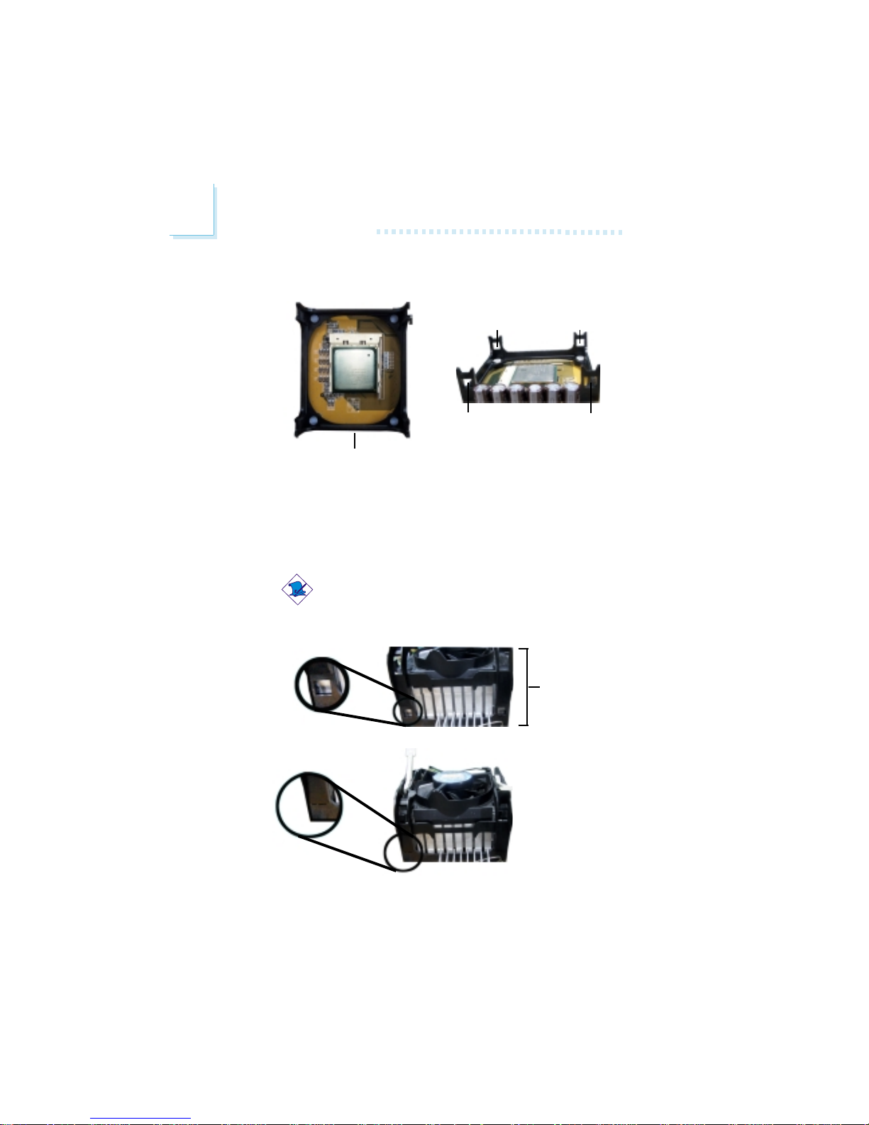
1. The system board comes with the retention module base already installed.
Retention
module base
Retention
hole
Retention
hole
Retention
hole
Retention
hole
2. Position the fan / heat sink and retention mechanism assembly
on the CPU, then align and snap the retention legs’ hooks to
the retention holes at the 4 corners of the retention module
base.
Note:
You will not be able to snap the hooks into the holes if the
fan / heat sink and retention mechanism assembly did not
fit properly onto the CPU and retention module base.
Unsnapped
Fan / heat sink
and retention
mechanism
assembly
Snapped
2
Hardware Installation
23
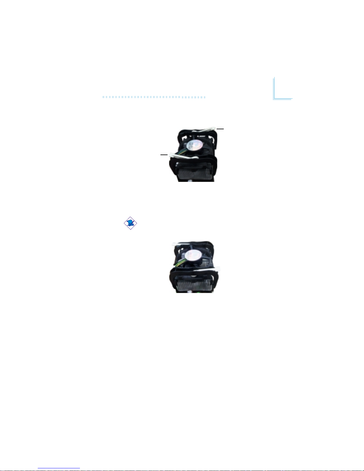
3. The retention levers at this time remains unlocked as shown
in the illustration below.
Retention lever
Retention lever
4. Move the retention levers to their opposite directions then
push them down. This will secure the fan / heat sink and retention mechanism assembly to the retention module base.
Note:
You will not be able to push the lever down if the direction
is incorrect.
5. Connect the CPU fan’s cable connector to the CPU fan connector on the system board.
2
24
Hardware Installation
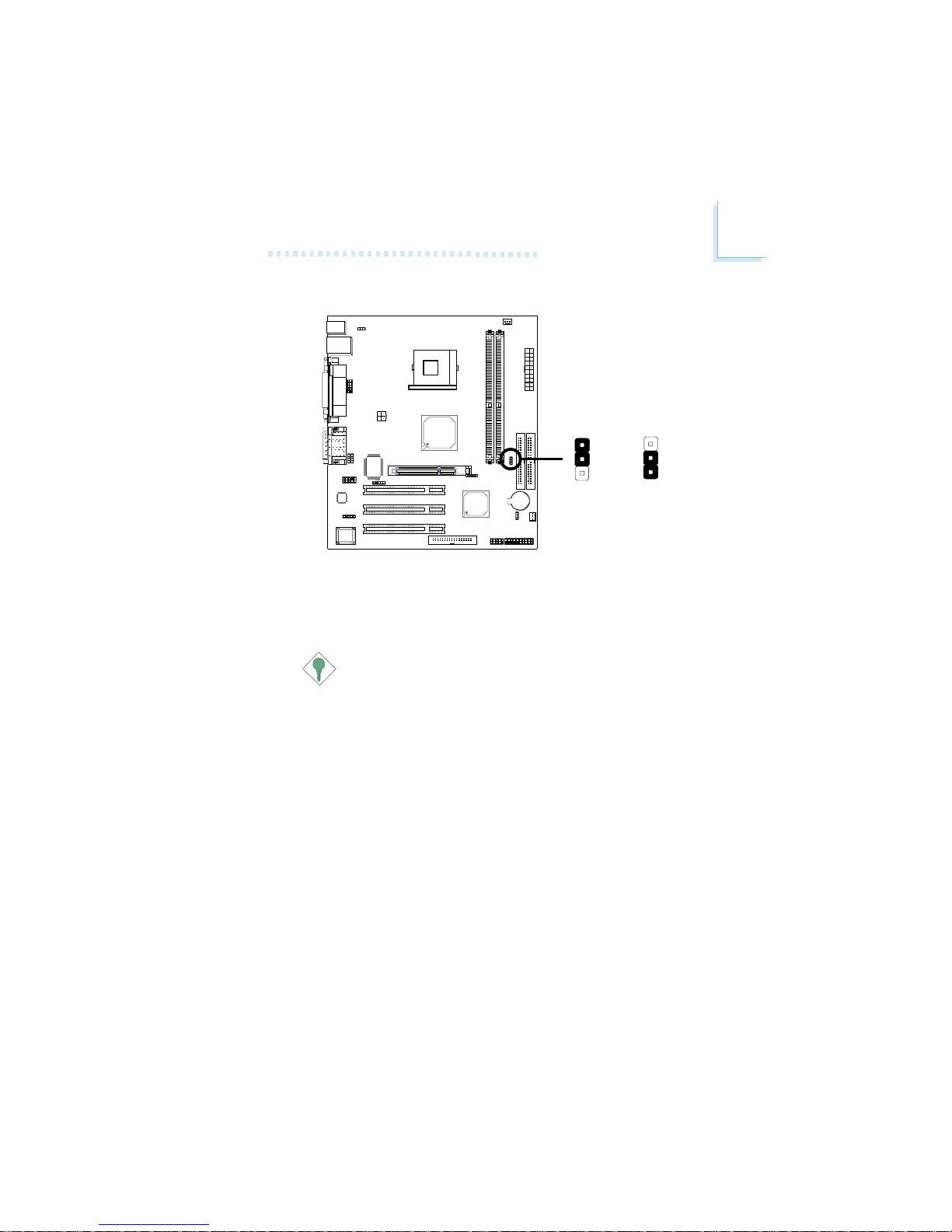
2.4 Jumper Settings
If you encounter the following,
a) CMOS data becomes corrupted.
b) You forgot the keyboard, supervisor or user password.
c) You are unable to boot-up the computer system because the proc-
essor’s ratio/clock was incorrectly set in the BIOS.
you can reconfigure the system with the default values stored in
the ROM BIOS.
To load the default values stored in the ROM BIOS, please follow
the steps below.
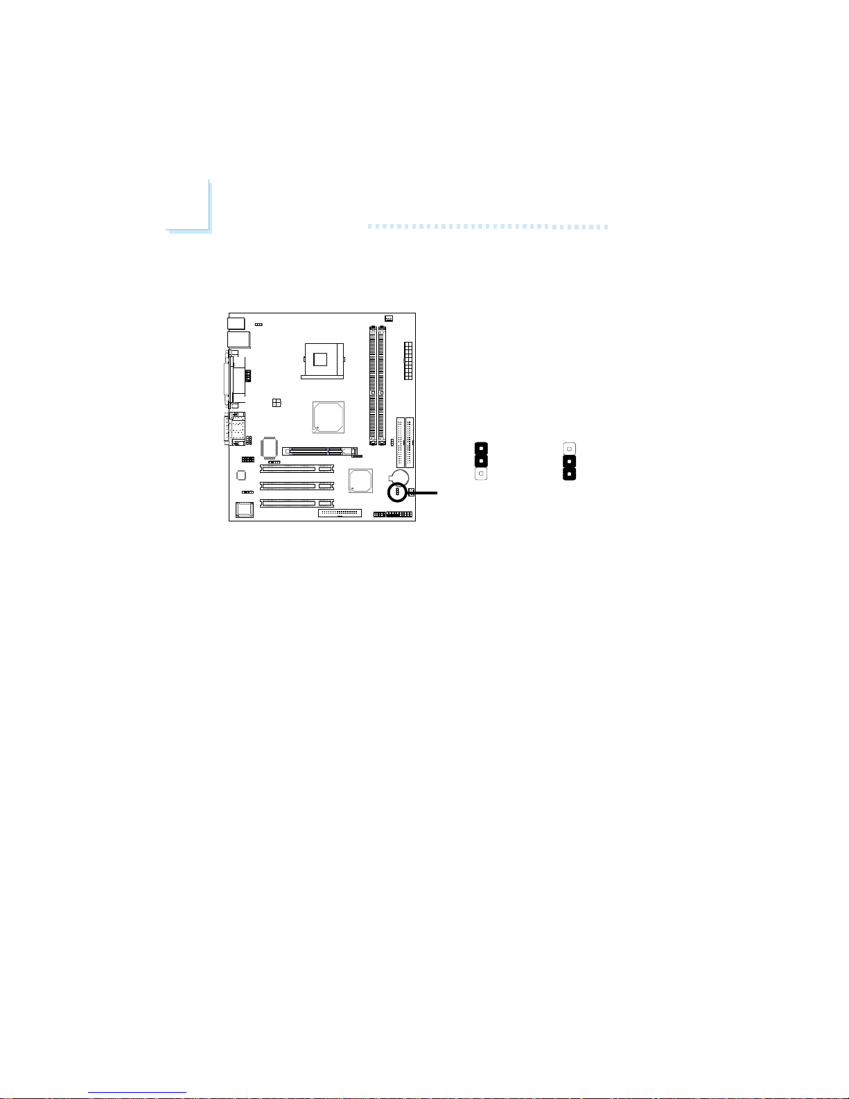
1. Power-off the system and unplug the power cord.
2. Set JP1 pins 2 and 3 to On. Wait for a few seconds and set JP1
back to its default setting, pins 1 and 2 On.
3. Now plug the power cord and power-on the system.
If your reason for clearing the CMOS data is due to incorrect
setting of the processor’s ratio/clock in the BIOS, please proceed to step 4.
2-3 On:
Clear CMOS Data
1-2 On: Normal
(default)
!
JP1
2.4.1 Jumper Settings for Clearing CMOS Data
1
3
2
1
3
2

2
Hardware Installation
25
4. After powering-on the system, press <Del> to enter the main
menu of the BIOS.
5. Select the Frequency/Voltage Control submenu and press
<Enter>.
6. Set the “CPU Clock Ratio” or “CPU Clock” field to its default
setting or an appropriate frequency ratio or bus clock. Refer
to the Frequency/Voltage Control section in chapter 3 for
more information.
7. Press <Esc> to return to the main menu of the BIOS setup
utility. Select “Save & Exit Setup” and press <Enter>.
8. Type <Y> and press <Enter>.

2
26
Hardware Installation
2.4.2 Jumper Settings for Selecting the PS/2 Power
!
JP2
This jumper is used to select the power of the PS/2 keyboard port.
BIOS Setting:
Selecting 5V_DUL will allow you to use the Wake-On-PS/2
Keyboard function. “PS2KB Wakeup Select” (“IRQ/Event Activity Detect” field) in the Power Management Setup submenu of the BIOS
must be set accordingly. Refer to chapter 3 for more information.
Important:
The 5VSB power source of your power supply must support
≥
720mA.
312
2-3 On: 5V_DUL
(default)
1-2 On: VCC
312
2
Hardware Installation
27
2.4.3 Jumper Settings for Selecting the CPU’s FSB
This jumper is used to select the front side bus of the CPU installed
on the system board. The default setting is Auto. The system will run
according to the front side bus of the CPU installed on the system
board.
Important:
• If you are using a CPU whose frequency has been locked
by the manufacturer, overclocking will have no effect.
• Overclocking may result to the CPU’s or system’s instability
and are not guaranteed to provide better system performance. If you are unable to boot your system due to
overclocking, make sure to set this jumper back to its
default setting.
1-2 On: Auto
(default)
!
2-3 On:
100MHz
1
3
2
1
3
2
J22
2
28
Hardware Installation
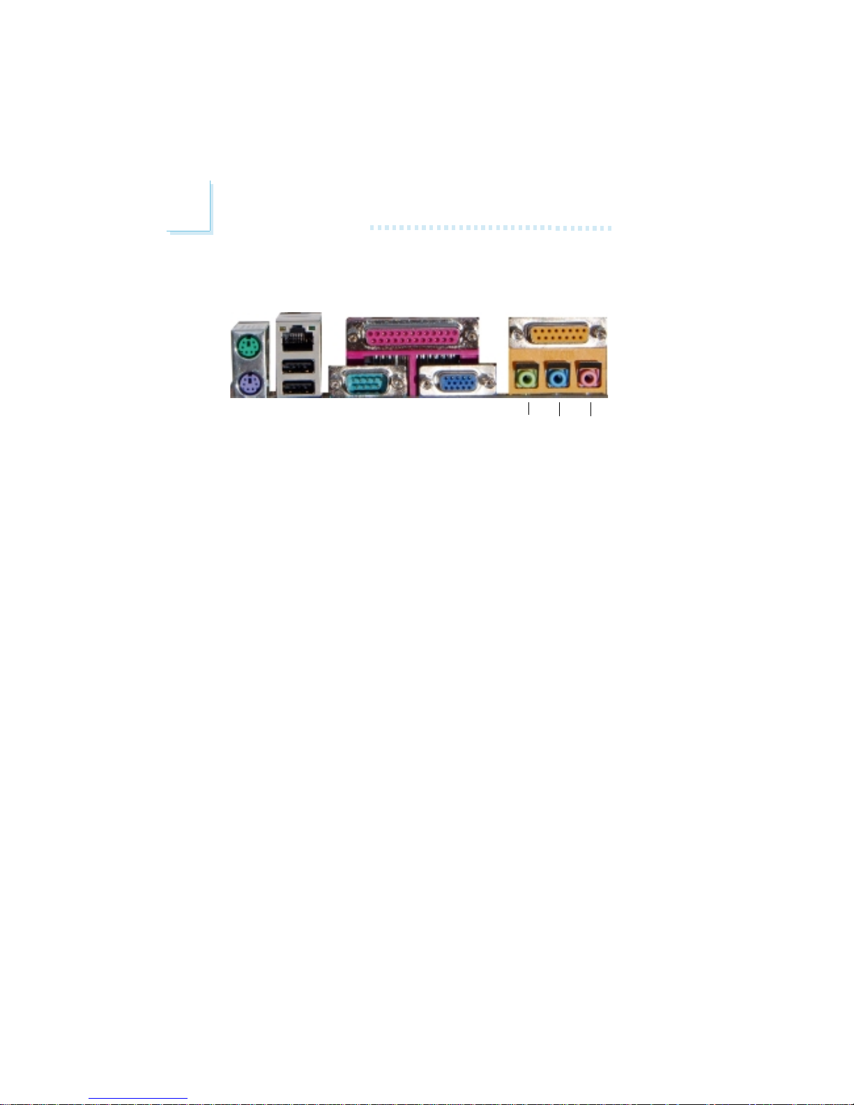
2.5 Rear Panel I/O Ports
The rear panel I/O ports consist of the following:
• PS/2 mouse port
• PS/2 keyboard port
• LAN port
• USB ports
• Parallel port
• COM 1 port
• VGA port
• Game port
• Line-out jack
• Line-in jack
• Mic-in jack
PS/2
Mouse
RJ45
LAN
Parallel GAME/MIDI
USB 1-2
COM 1 VGA
Line-
out
Line-inMic-
in
PS/2
K/B
2
Hardware Installation
29
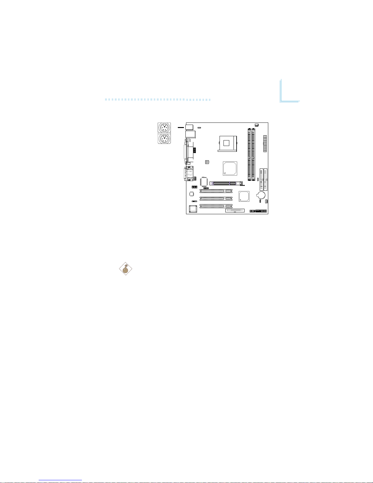
2.5.1 PS/2 Mouse and PS/2 Keyboard Ports
The system board is equipped with an onboard PS/2 mouse
(Green) and PS/2 keyboard (Purple) ports - both at location J11 of
the system board. The PS/2 mouse port uses IRQ12. If a mouse is
not connected to this port, the system will reserve IRQ12 for other
expansion cards.
Warning:
Make sure to turn off your computer prior to connecting or
disconnecting a mouse or keyboard. Failure to do so may damage the system board.
Wake-On-PS/2 Keyboard
The Wake-On-PS/2 Keyboard function allows you to use a PS/2
keyboard to wake up the system from the S5 state. To use this
function:
• Jumper Setting:
JP2 must be set to “2-3 On: 5V_DUL”. Refer to “Jumper Settings for Selecting the PS/2 Power” in this chapter for more
information.
• BIOS Setting:
“PS2KB Wakeup Select” (“IRQ/Event Activity Detect” field) in
the Power Management Setup submenu of the BIOS must be
set accordingly. Refer to chapter 3 for more information.
.
.
.
.
.
.
.
.
PS/2 Mouse
PS/2 Keyboard
"
2
30
Hardware Installation
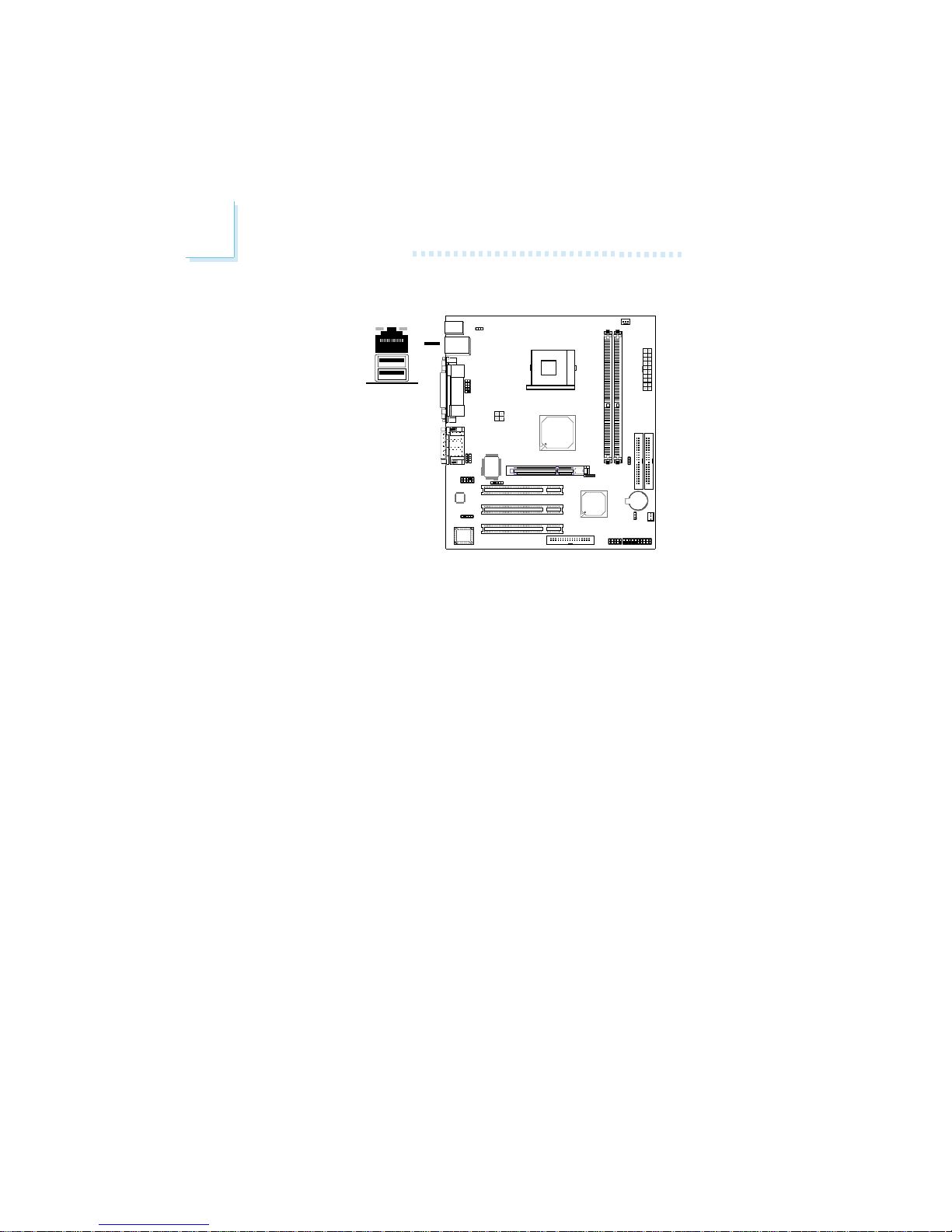
2.5.2 RJ45 Fast-Ethernet Port
The system board is equipped with an onboard RJ45 fast-ethernet
LAN port at location CN1 of the system board. It allows the
system board to connect to a local area network by means of a
network hub.
BIOS Setting
Configure the onboard LAN in the Integrated Peripherals submenu
(“VIA OnChip PCI Device” field) of the BIOS. Refer to chapter 3 for
more information.
Driver Installation
Install the “VIA LAN Drivers”. Refer to chapter 4 for more information.
RJ45 LAN
"
 Loading...