

DFI P2XBL User Manual

P2XBL
Rev. C+
System Board
Carte Mère Manuel
System-Platine
Users Manual
Pour Utilisateur
Benutzerhandbuch
35290847

Copyright
This publication contains information that is protected by copyright. No part of it may
be reproduced in any form or by any means or used to make any transformation/
adaptation without the prior written permission from the copyright holders.
This publication is provided for informational purposes only. The manufacturer makes
no representations or warranties with respect to the contents or use of this manual and
specifically disclaims any express or implied warranties of merchantability or fitness
for any particular purpose. The user will assume the entire risk of the use or the results
of the use of this document. Further, the manufacturer reserves the right to revise this
publication and make changes to its contents at any time, without obligation to notify
any person or entity of such revisions or changes.
© 1998. All Rights Reserved.
Trademarks
Microsoft
®
MS-DOS®, WindowsTM and Windows® 95 are registered trademarks of
Microsoft Corporation. Intel
®
, Pentium® II and CeleronTM are registered trademarks of
Intel Corporation. Award is a registered trademark of Award Software, Inc. Other
trademarks and registered trademarks of products appearing in this manual are the
properties of their respective holders.
Caution:
Danger of explosion if battery incorrectly replaced.
Replace only with the same or equivalent type recommended by the
manufacturer.
Dispose of used batteries according to the battery manufacturers instructions.
FCC and DOC Statement on Class B
This equipment has been tested and found to comply with the limits for a Class
B digital device, pursuant to Part 15 of the FCC rules. These limits are designed
to provide reasonable protection against harmful interference when the
equipment is operated in a residential installation. This equipment generates, uses
and can radiate radio frequency energy and, if not installed and used in
accordance with the instruction manual, may cause harmful interference to radio
communications. However, there is no guarantee that interference will not occur
in a particular installation. If this equipment does cause harmful interference to
radio or television reception, which can be determined by turning the equipment
off and on, the user is encouraged to try to correct the interference by one or
more of the following measures:
Reorient or relocate the receiving antenna.
Increase the separation between the equipment and the receiver.
Connect the equipment into an outlet on a circuit different from that to
which the receiver is connected.
Consult the dealer or an experienced radio TV technician for help.
Notice:
1. The changes or modifications not expressly approved by the party
responsible for compliance could void the user's authority to operate the
equipment.
2. Shielded interface cables must be used in order to comply with the emission
limits.

Table of Contents / Sommaire / Inhaltsverzeichnis
Note:
The users manual in the provided CD contains detailed information
about the system board. If, in some cases, some information doesnt
match those shown in this manual, this manual should always be
regarded as the most updated version. To view the users manual,
insert the CD into a CD-ROM drive. The autorun screen (Main Board
Utility CD) will appear. Click Users Manual.
Chapter 1 - Introduction
1.1 Features and Specifications...................................................................
1.2 Package Checklist ......................................................................................
Chapter 2 - Hardware Installation
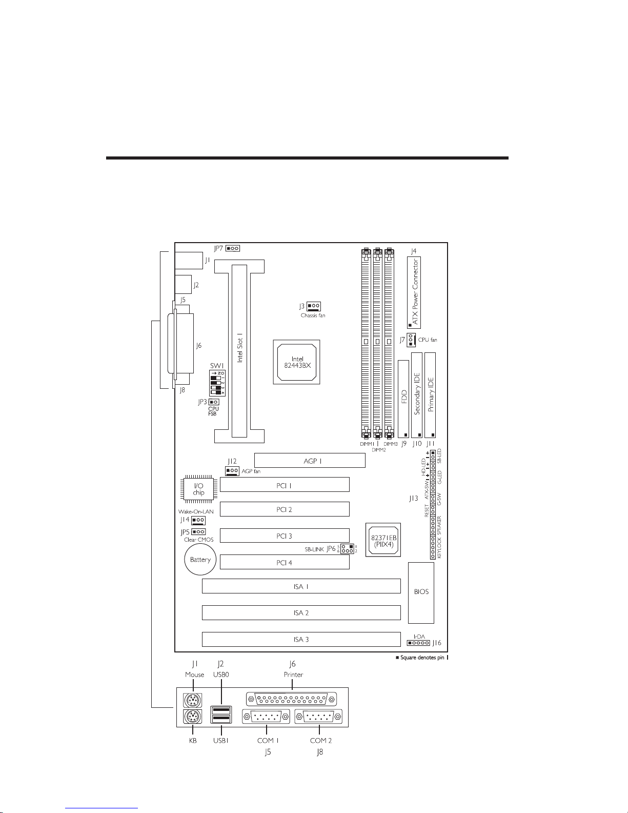
2.1 System Board Layout ..............................................................................
2.2 DIP Switch Settings of the Processors .........................................
2.3 Jumper Settings for Clearing CMOS Data.................................
2.4 Jumper Settings for CPU Front Side Bus....................................
2.5 Jumper Settings for Wake-On-Keyboard/Mouse .....................
2.6 Connectors ....................................................................................................
Chapter 3 - Award BIOS Setup Utility
3.1 Entering the Award BIOS Setup Utility ........................................
3.2 Setting the Date and Time...................................................................
3.3 Selecting the Hard Drive and Floppy Drive Type...................
3.4 Selecting the Drive to be Searched First for an
Operating System......................................................................................
3.5 Setting the External System Bus Clock of the Processor..
3.6 Selecting an IRQ for the External Modem .................................
3.7 Selecting the Method of Powering-off the System.................
3.8 Selecting the Power Lost Resume State ......................................
3.9 Selecting the Wake-On-Keyboard/Mouse Function................
3.10 Using the System Health Monitor Function ...............................
3.11 Loading Fail-Safe Settings/Optimal Settings ...............................
3.12 Setting the Supervisor/User Password .........................................
Chapter 4 - Supported Softwares
4.1 Drivers and Utility ....................................................................................
Appendix A - System Error Messages
A.1 POST Beep ...................................................................................................
A.2 Error Messages............................................................................................
4
7
19
20
21
22
23
25
26
28
29
33
36
36
8
9
10
11
12
13
38
39
39

4
1.1 Features and Specifications
Caractéristiques et Spécifications
Leistungsmerkmale und Technische Daten
1.1.1 Features / Caractéristiques / Leistungsmerkmale
Chipset
Intel 440BX AGPset
Processor
233/66MHz, 266/66MHz, 300/66MHz, 333/66MHz,
350/100MHz, 400/100MHz or 450/100MHz Pentium II
processor with 512KB L2 cache
266/66MHz, 300/66MHz, 300A/66MHz, 333/66MHz
Intel CeleronTM processor
System Memory
The system board supports 8MB to 768MB memory. It is equipped
with three 168-pin DIMM sockets using x64/x72 unbuffered or
registered PC SDRAM, 3.3V. The PC SDRAMs supported are PC-66
SDRAM for 66MHz FSB and PC-100 SDRAM for 100MHz FSB. The
system board also supports ECC (uses x72 PC SDRAM).
Expansion Slots
The system board is equipped with 1 dedicated AGP slot, 3
dedicated PCI slots, 2 dedicated 16-bit ISA slots and 1 shared PCI/
ISA slot. All PCI and ISA slots are bus masters.
Desktop Management Interface (DMI)
The system board comes with a DMI 2.0 built into the BIOS. The
DMI utility in the BIOS automatically records various information
about your system configuration and stores these information in the
DMI pool, which is a part of the system board's Plug and Play
BIOS. DMI, along with the appropriately networked software, is
designed to make inventory, maintenance and troubleshooting of
computer systems easier.
Chapter 1 - Introduction / Introduction / Einleitung
DIMMs
1MBx64/x72
2MBx64/x72
4MBx64/x72
Memory Size
8MB
16MB
32MB
DIMMs
8MBx64/x72
16MBx64/x72
32MBx64/x72
Memory Size
64MB
128MB
256MB*
* Registered DIMM only.

1
Introduction
5
ATX Double Deck Ports
2 USB ports
2 DB-9 serial ports
1 DB-25 parallel port
1 mini-DIN-6 PS/2 keyboard port
1 mini-DIN-6 PS/2 mouse por t
Connectors
1 connector for IrDA interface
2 IDE connectors
1 floppy connector
1 20-pin ATX power supply connector
1 3-pin WOL (Wake-On-LAN) connector
1 SB-LINK connector
3 fan connectors for CPU, chassis and AGP fans
PCI Bus Master IDE Controller
Two PCI IDE interfaces support up to four IDE devices
Ultra DMA/33 supported (Synchronous Ultra DMA mode - data
transfer rate up to a maximum of 33MB/sec.)
PIO Mode 3 and Mode 4 Enhanced IDE (data transfer rate up
to 16.6MB/sec.)
Bus mastering reduces CPU utilization during disk transfer
ATAPI CD-ROM, LS-120 and ZIP supported
IrDA Interface
The system board is equipped with an IrDA connector for wireless
connectivity between your computer and peripheral devices. It
supports peripheral devices that meet the IrDA or ASKIR standard.
USB Ports
The system board is equipped with two USB por ts. USB allows
data exchange between your computer and a wide range of
simultaneously accessible external Plug and Play peripherals.
BIOS
Award BIOS, Windows 95 Plug and Play compatible
Flash EPROM for easy BIOS upgrades
1.1.2 Intelligence / Intelligence / Intelligente Ausstattungsteile
Monitors Processor Temperature and Overheat Alarm
The system board is able to detect the temperature of the
processor. An alarm will sound in case of processor overheat.

Introduction
1
6
Monitors Processor/Chassis Fan Speed and Failure Alarm
The system board is able to detect the fan speed (RPM-Revolution
Per Minute) and alerts you to attend to any irregularity that may
damage your system.
Monitors Power Voltages and Failure Alarm
The system board is able to detect the output voltage of the power
supply. An alarm will sound warning you of voltage irregularity.
Automatic Fan Off
The CPU fan will automatically turn off once the system enters the
Suspend mode. This prevents system overheat and prolongs fan life.
Dual Function Power Button
Depending on the setting in the BIOS setup, this switch will allow
your system to enter the Soft-Off or Suspend mode.
External Modem Ring-on
The Modem Ring-on feature allows the system that is in the
Suspend mode or Soft Power Off mode to wake-up/power-on to
respond to incoming calls. This feature supports external modem
only.
RTC Timer to Power-on the System
The RTC installed on the system board allows your system to
automatically power-on on the set date and time.
Wake-On-LAN Ready
The Wake-On-LAN function allows the network to remotely wake
up a Soft Power Down (Soft-Off) PC. Your LAN card must support
the remote wakeup function.
Important:
The 5VSB power source of your power supply must support
≥
720mA (minimum).
Wake-On-Keyboard/Wake-On-Mouse
This function allows you to use the keyboard or mouse to power-on
the system. Refer to sections 2.5 (chapter 2) and 3.9 (chapter 3) for
more information.
Important:
The power button will not function once a keyboard password
has been set in the KB Power On Password field of the
Integrated Peripherals setup. You must type the password to
power-on the system.

1
Introduction
7
Virus Protection
Most viruses today destroy data stored in hard drives. The system
board is designed to protect the boot sector and partition table of
your hard disk drive.
1.2 Package Checklist
Liste de Vérification de lEmballage
Verpackungsliste
The system board package contains the following items:
The system board
A users manual
One 40-pin IDE hard disk cable
One 34-pin floppy disk drive cable
One CD
If any of these items are missing or damaged, please contact your
dealer or sales representative for assistance.
8
2.1 System Board Layout
Position de la Carte Système
Aufbau der Hauptplatine
Chapter 2 - Hardware Installation
Installation du Matériel
Installation der Hardware
2
Hardware Installation
9
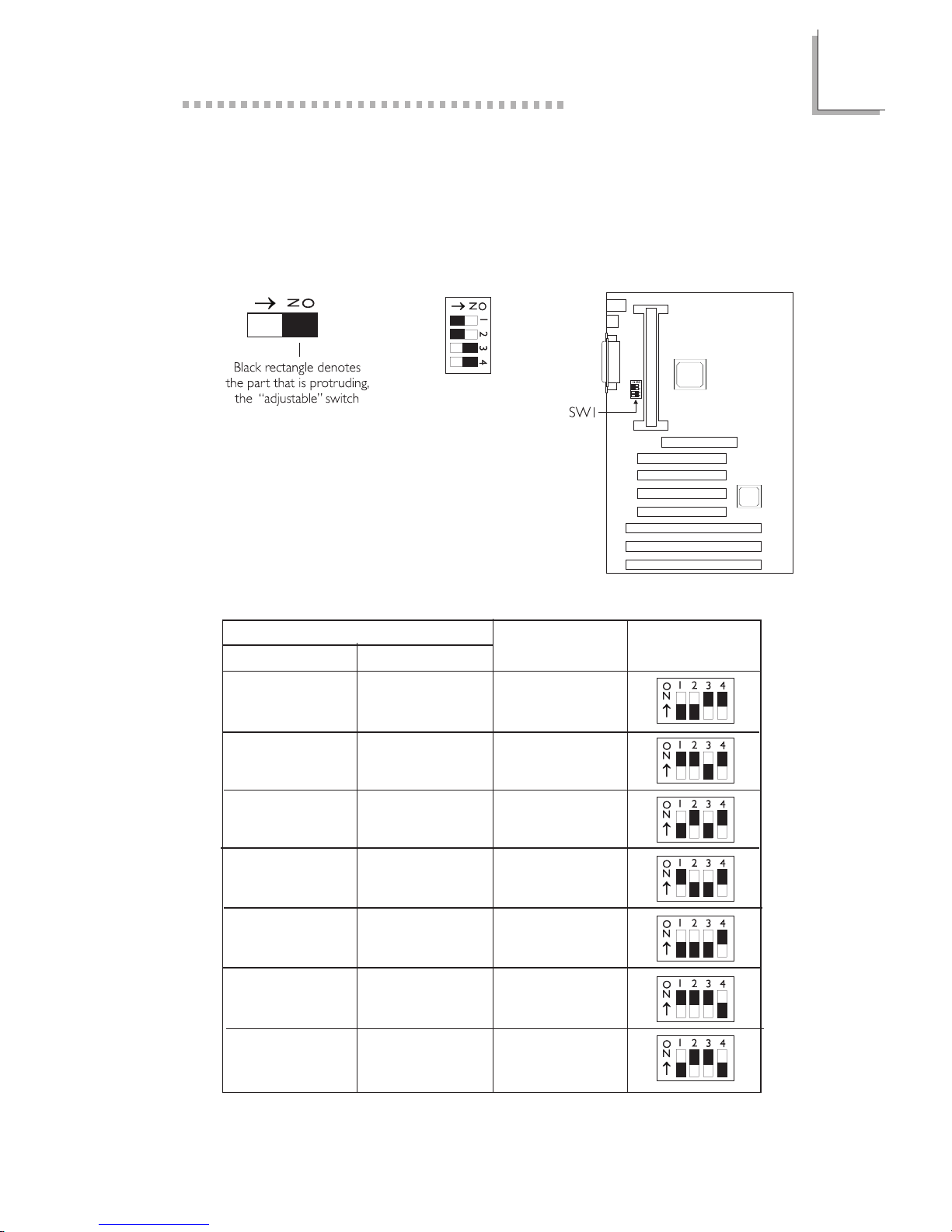
2.2 DIP Switch Settings of the Processors
Positionnement des Cavaliers des Processeurs
DIP Schaltereinstellungen für den Prozessor
The table below shows the supported processors and their
corresponding DIP switch settings.
In the example above:
Switch 1: Off
Switch 2: Off
Switch 3: On
Switch 4: On
Processor
SW1
66MHz 100MHz
Frequency Ratio
233MHz 350MHz 3.5x
266MHz 400MHz 4x
300MHz 450MHz 4.5x
Future processor Future processor 5.5x
Future processor Future processor 6x
333MHz Future processor 5x
Future processor Future processor 6.5x
2
10
Hardware Installation
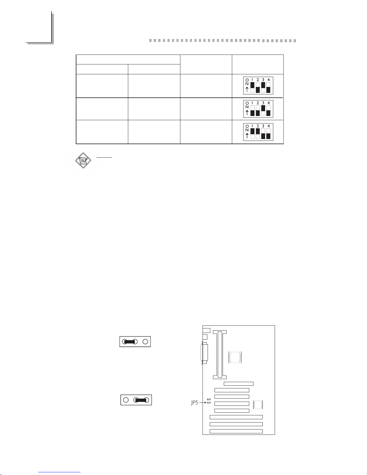
2.3 Jumper Settings for Clearing CMOS Data
Positionnement des Cavaliers pour Effacer les Données
CMOS
Jumpereinstellungen zum Löschen der CMOS Daten
Jumper JP5 - CMOS Clear
To load the default values stored in the ROM BIOS, please follow
the steps below.
1. Power-off the system and unplug the power cord.
2. Set JP5 pins 2 and 3 to On. Wait for a few seconds and set JP5 back
to its default setting, pins 1 and 2 On.
3. Plug the power cord and power-on the system.
Future processor Future processor 7x
Future processor Future processor 7.5x
Future processor Future processor 8x
Processor
SW1
66MHz 100MHz
Frequency Ratio
Note:
Intel Pentium
II processor or Intel CeleronTM processor supports VID
(Voltage Identification). The switching voltage regulator on the system
board will automatically set the voltage regulator according to the voltage
of the processor.
1-2 On: Normal
(default)
2-3 On:
Clear CMOS Data
123
123
2
Hardware Installation
11
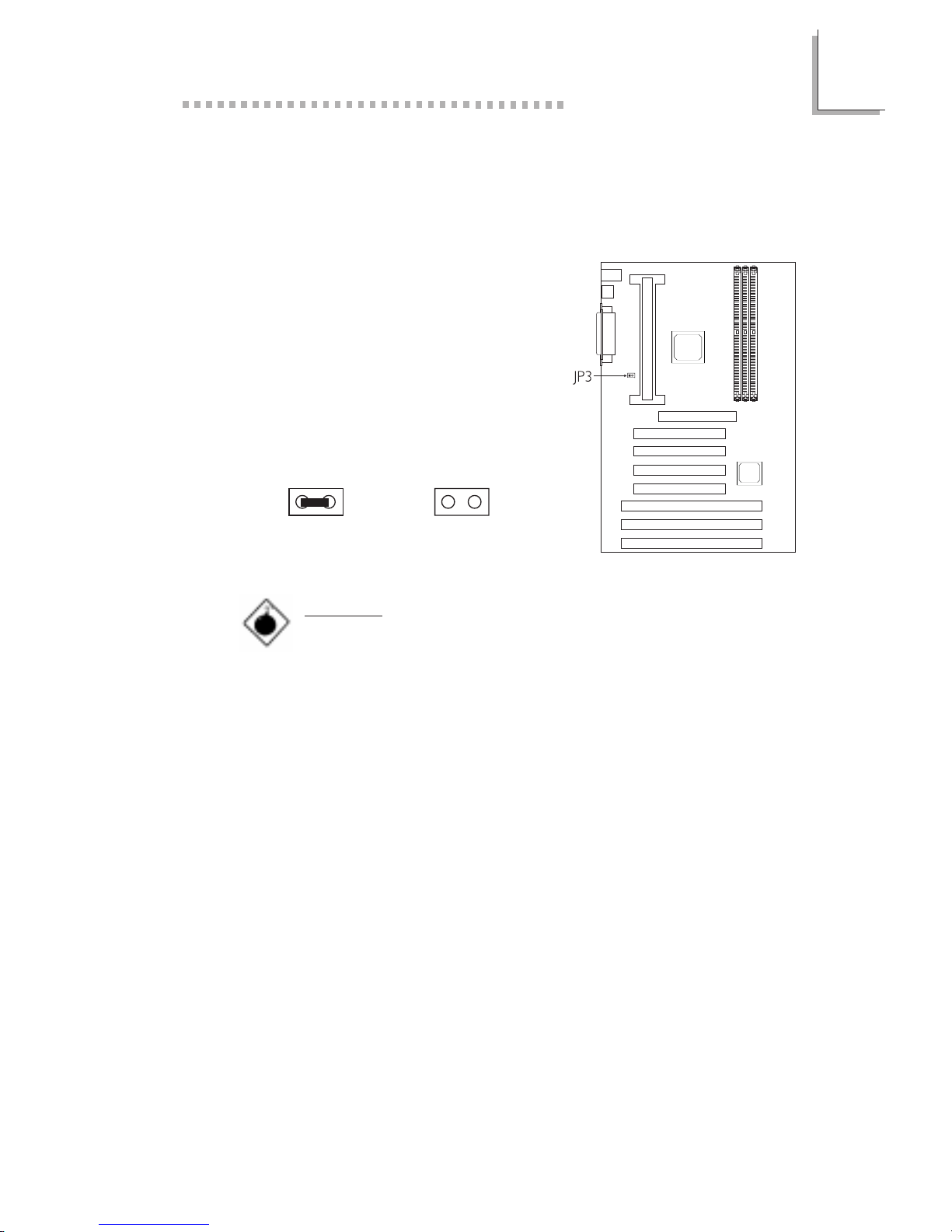
2.4 Jumper Settings for CPUs Front Side Bus
Positionnement des cavaliers pour le bus frontal du
processeur
Jumpereinstellungen fuer CPU Vorderseitenbus
The default setting of jumper JP3 is
Auto - the system will automatically run
according to the FSB of the processor.
If you wish to overclock a 66MHz FSB
processor to 100MHz, set pins 1 and
2 to Off.
On : Auto(default) Off : 100MHz
Warning:
Overclocking a 66MHz FSB processor to 100MHz willl
provide better system performance. However, not all 66MHz
FSB processors are capable of running at 100MHz bus
speed. Therefore, if you are unable to boot your system when
set at 100MHz, make sure to set JP3 back to its default
setting.
1212
2
12
Hardware Installation
2.5 Jumper Settings for Wake-On-Keyboard/Mouse
Positionnement des Cavaliers pour Réveil-Sur-Clavier/
Souris
Jumpereinstellungen für die Wake-On Tastatur/Maus
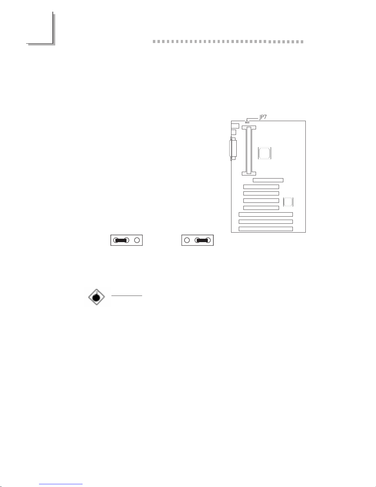
Jumper JP7 - Wake-on-Keyboard/Mouse
To use the keyboard or mouse to power-
on the system, please follow the steps
below.
1. Set JP7 to 2-3 On, enable.
2. Keyboard/Mouse Power On in the
Integrated Peripherals setup of the
Award BIOS must be set accordingly.
Refer to section 3.9 (chapter 3) for
more information.
Warning:
1. The power button will not function once a keyboard
password has been set in the KB Power On Password
field of the Integrated Peripherals setup. You must type
the password to power-on the system.
2. The 5VSB power source of your power supply must
support ≥720mA (minimum).
1-2 On: Disable
(default)
123
2-3 On: Enable
123
 Loading...