

DFI NS36-TC, NS36-TL User Manual

NS36-TC
NS36-TL
Rev. A+
System Board User’s Manual
Carte Mère Manuel Pour Utilisateur
System-Platine Benutzerhandbuch
Tablero Electrónico del Sistema Manual del Usuario
935-NS3601-100
63000232
63000232 1.pmd 9/13/02, 1:35 PM1

Copyright
This publication contains information that is protected by copyright.
No par t of it may be reproduced in any form or by any means or
used to make any transformation/adaptation without the prior
written permission from the copyright holders.
This publication is provided for informational purposes only. The
manufacturer makes no representations or warranties with respect to
the contents or use of this manual and specifically disclaims any
express or implied warranties of merchantability or fitness for any
par ticular purpose . The user will assume the entire risk of the use or
the results of the use of this document. Further, the manufacturer
reserves the r ight to revise this publication and make changes to its
contents at any time, without obligation to notify any person or
entity of such revisions or changes.
© 2002. All Rights Reserved.
Trademarks
Windows® 98, Windows® 98 SE, Windows® ME, Windows® 2000,
Windows NT® 4.0 and Windows® XP are registered trademarks of
Microsoft Corporation. Intel® and Pentium® 4 are registered
trademarks of Intel Corporation. SiS® is a registered trademark of
Silicon Integrated Systems Corporation. Award is a registered
trademark of Award Software, Inc. Other trademarks and registered
trademarks of products appear ing in this manual are the properties
of their respective holders.
Caution
To avoid damage to the system:
• Use the correct AC input voltage r ange
..
..
.
To reduce the risk of electr ic shock:
• Unplug the power cord before removing the system chassis
cover for installation or servicing. After installation or ser vicing,
cover the system chassis before plugging the power cord.
63000232 1.pmd 9/13/02, 1:35 PM2

Battery:
• Danger of explosion if batter y incor rectly replaced.
• Replace only with the same or equivalent type recommend
by
the manufacturer.
• Dispose of used batteries according to the battery
manufacturer’s
instructions.
Joystick or MIDI por t:
• Do not use any joystick or MIDI device that requires more than
10A current at 5V DC. There is a risk of fire for devices that
exceed this limit.
FCC and DOC Statement on Class B
This equipment has been tested and found to comply with the limits
for a Class B digital device, pursuant to Par t 15 of the FCC rules.
These limits are designed to provide reasonable protection against
harmful interference when the equipment is operated in a residential
installation. This equipment generates, uses and can radiate radio
frequency energy and, if not installed and used in accordance with
the instruction manual, may cause harmful interference to radio
communications. However, there is no guarantee that interference
will not occur in a par ticular installation. If this equipment does cause
harmful interference to radio or television reception, which can be
determined by turning the equipment off and on, the user is
encouraged to tr y to correct the interference by one or more of the
following measures:
• Reorient or relocate the receiving antenna.
• Increase the separation between the equipment and the receiver.
• Connect the equipment into an outlet on a circuit different from
that to which the receiver is connected.
• Consult the dealer or an experienced radio TV technician for
help.
Notice:
1. The changes or modifications not expressly approved by the
par ty responsible for compliance could void the user's authority
to operate the equipment.
2. Shielded interface cables must be used in order to comply with
the emission limits.
63000232 1.pmd 9/13/02, 1:35 PM3

4
Quick Setup Guide
1
Quick Setup
Guide
Table of Contents
Chapter 1
Quick Setup Guide.............................................
Chapter 2
English......................................................................
Chapter 3
Français (French).................................................
Chapter 4
Deutsch (German)................................................
Chapter 5
Español (Spanish)..................................................
5
26
43
62
82
Note:
This user’s manual is for the NS36-TC and NS36-TL system boards.
The only difference between these boards is the NS36-TL system
board supports onboard LAN.
63000232 1.pmd 9/13/02, 1:35 PM4

5
1
Quick Setup Guide
Quick Setup
Guide
Chapter 1 - Quick Setup Guide
Table of Contents
1.1 System Board Layout..................................................................................................
1.2 Jumpers.....................................................................................................................................
1.3 Rear Panel I/O Ports...................................................................................................
1. 4 I/O Connectors................................................................................................................
1.5 Award BIOS Setup Utility.......................................................................................
6
8
10
15
21
63000232 1.pmd 9/13/02, 1:35 PM5
6
Quick Setup Guide
1
Quick Setup
Guide
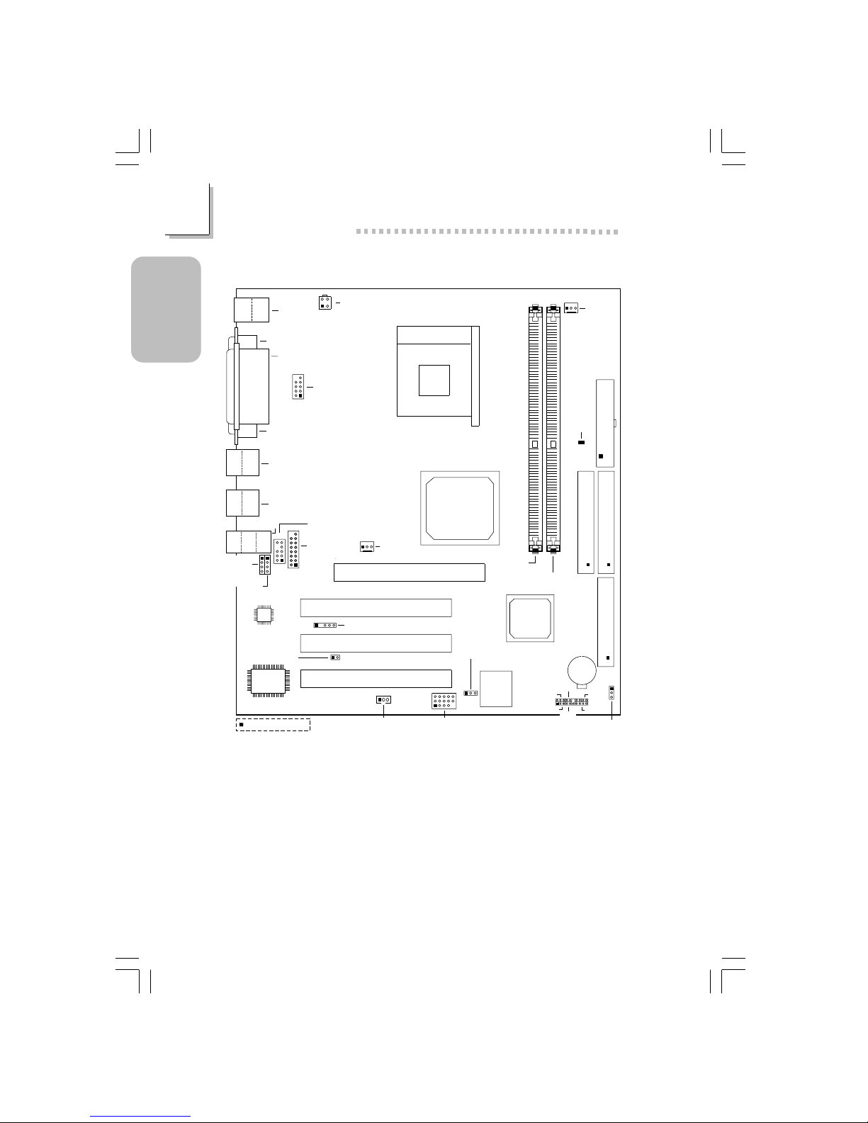
1.1 System Board Layout
NS36-TC
Clear CMOS (JP5)
FDD (J22)
SiS
651
SiS
962L
J2
KB
Mouse
COM 1 (J4)
Parallel (J5)
ATX Power
2
1
10
9
Front audio
(J10)
AC’97
3.3VSB standby
for PCI (JP6)
J3
1
5
11 15
USB5&6(J25)
BIOS
CPU fan
(J1)
DIMM
standby
power
LED
PCI1Slot
PCI2Slot
PCI3Slot
Socket 478
AGP Slot
+12V power
(ATXP1)
3
4
1
2
I/O
chip
System fan
(J12)
IrDA (J20)
J8
PWR-LED
HD-LED
J27
ATX-SW
G-SW
SPEAKER
Battery
RESET
DDR SDRAM
DIMM 1
DDR SDRAM
DIMM 2
Primary IDE (J18)
Seconary IDE (J17)
VGA (J7)
Square denotes pin 1
Wake-On-LAN (J23)
USB 1
USB 2
Line-
out
Line-
in
Mic-
in
CN1
CN3
16
15
2
1
CD-in
(J16)
Game/MIDI
(J13)
AUX-in
(J15)
Power select
for USB 5/6 (JP3)
10
9
2
1
COM 2 (J6)
USB 3
USB 4
63000232 1.pmd 9/13/02, 1:35 PM6
7
1
Quick Setup Guide
Quick Setup
Guide
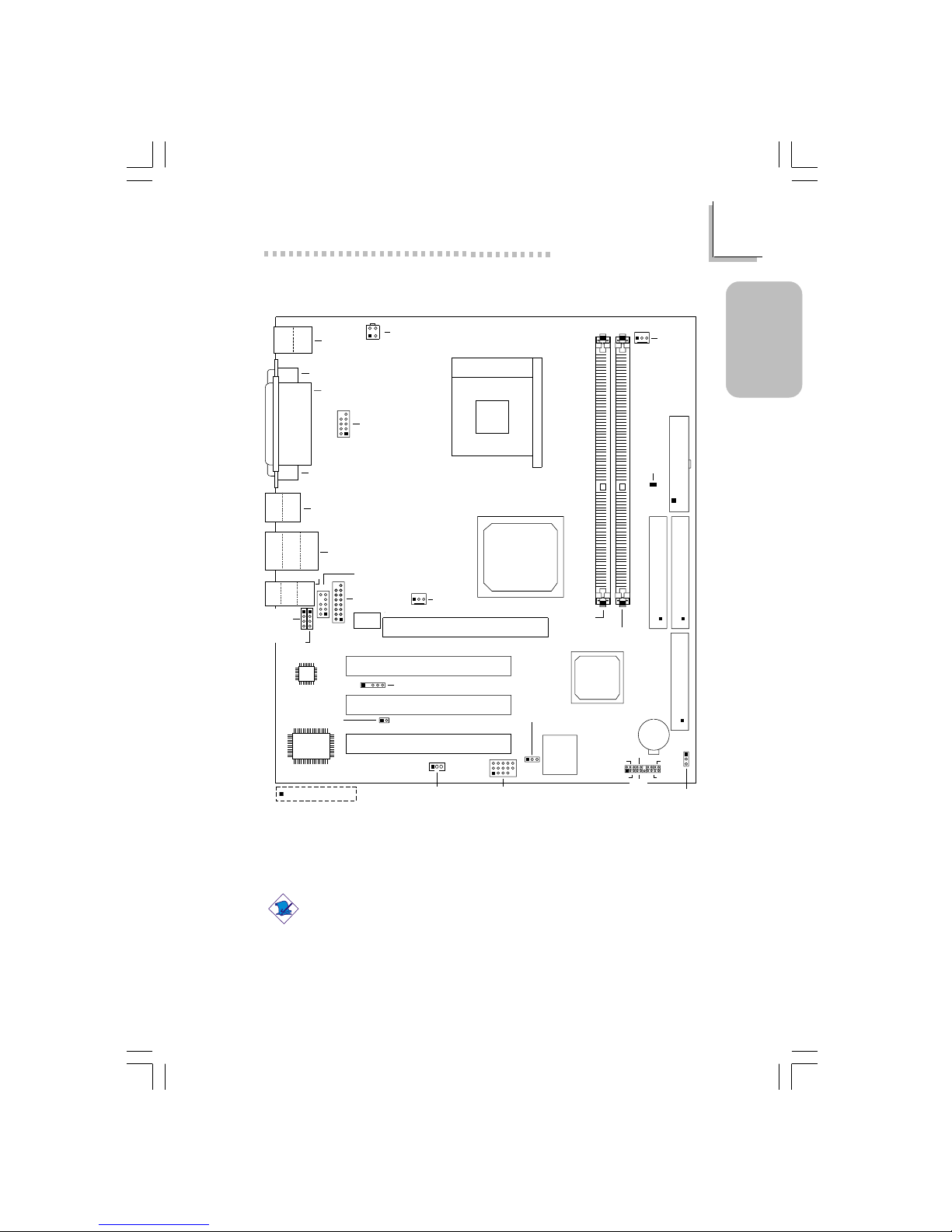
Note:
The illustrations on the following pages are based on the system
board that supports onboard LAN.
NS36-TL
(Supports onboard LAN)
Clear CMOS (JP5)
FDD (J22)
SiS
651
SiS
962L
J2
KB
Mouse
LAN
COM 1 (J4)
Parallel (J5)
ATX Power
2
1
10
9
Front audio
(J10)
AC’97
3.3VSB standby
for PCI (JP6)
J3
1
5
11 15
USB5&6(J25)
BIOS
CPU fan
(J1)
DIMM
standby
power
LED
USB 3
USB 4
PCI 1 Slot
PCI 2 Slot
PCI 3 Slot
Socket 478
AGP Slot
+12V power
(ATXP1)
3
4
1
2
I/O
chip
System fan
(J12)
IrDA (J20)
J8
PWR-LED
HD-LED
J27
ATX-SW
SPEAKER
Battery
RESET
DDR SDRAM
DIMM 1
DDR SDRAM
DIMM 2
Primary IDE (J18)
Seconary IDE (J17)
VGA (J7)
Square denotes pin 1
Wake-On-LAN (J23)
USB 1
USB 2
Line-
out
Line-
in
Mic-
in
CN1
CN3
16
15
2
1
Phy
CD-in
(J16)
Game/MIDI
(J13)
AUX-in
(J15)
Power select
for USB 5/6 (JP3)
10
9
2
1
COM 2 (J6)
G-SW
63000232 1.pmd 9/13/02, 1:35 PM7
8
Quick Setup Guide
1
Quick Setup
Guide
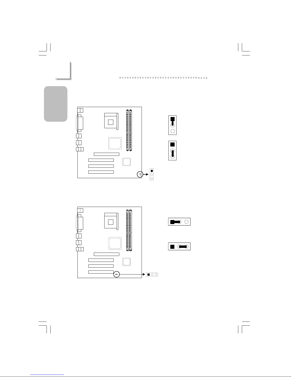
1.2.1 Clear CMOS Data - JP5
1.2 Jumpers
1
2
3
1
2
3
1-2 On:
Clear CMOS Data
2-3 On: Normal
(default)
1.2.2 Jumper Settings for Selecting the USB 5/6 Power - JP3
123
1-2 On: Disabled - VCC
1
23
2-3 On: Enabled 5V_DUL
(default)
If you wish to use the Wake-On-USB Keyboard/Mouse function, make sure
this jumper is set to Enabled. “USB Port Wake Up Control” (“PM Wake Up
Events” field) in the Power Management Setup submenu of the BIOS must
also be set to Enabled.
Clear CMOS
(JP5)
1
2
3
Power select
for USB 5/6 (JP3)
12
3
63000232 1.pmd 9/13/02, 1:35 PM8
9
1
Quick Setup Guide
Quick Setup
Guide
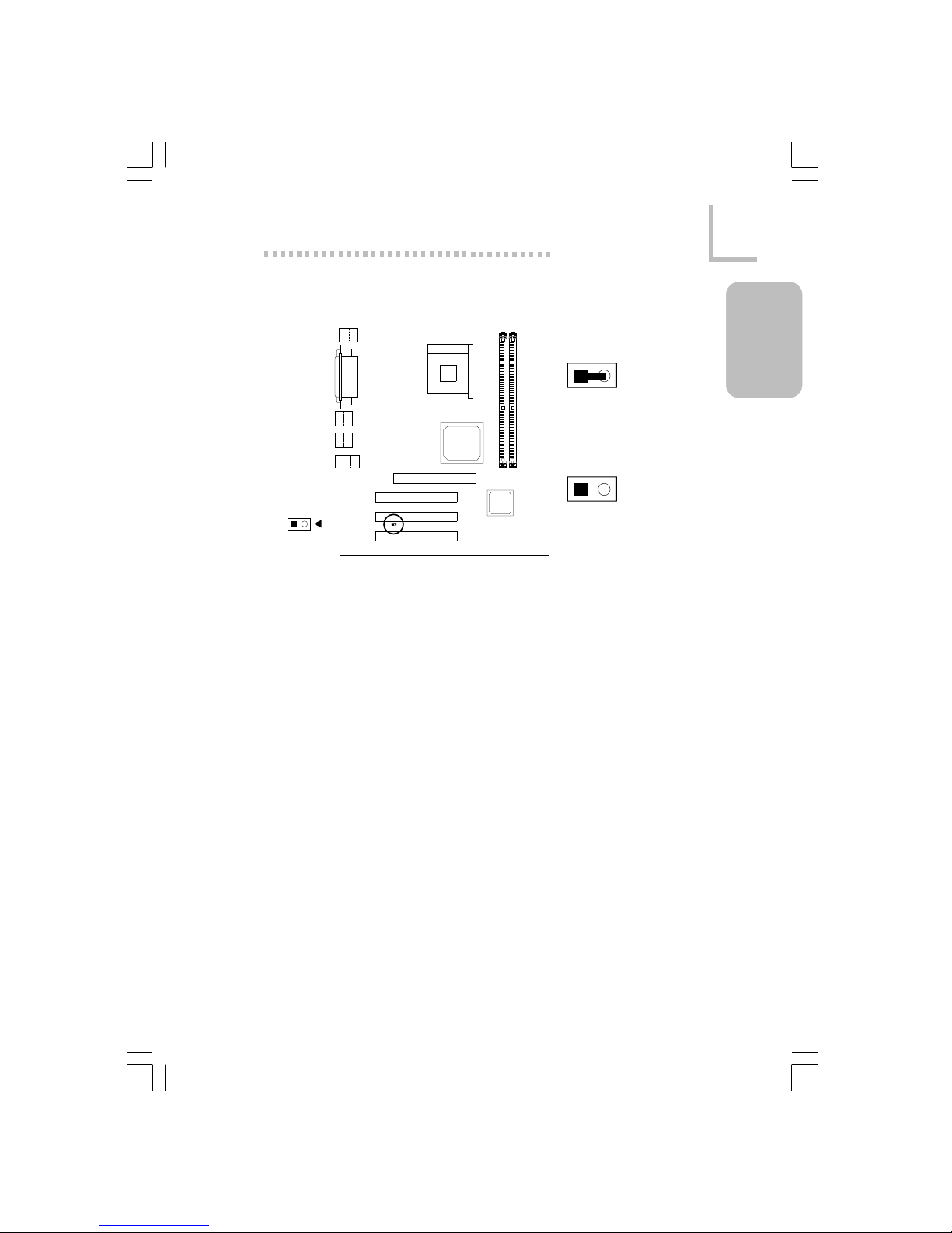
1.2.3 Jumper Settings for 3.3VSB Standby for PCI - JP6
On: Default
3.3VSB Standby Power to
PCI Slots - PCI 2.2 spec.
Off: Non-PCI 2.2 spec.
3.3VSB standby
for PCI (JP6)
21
12
12
63000232 1.pmd 9/13/02, 1:35 PM9
10
Quick Setup Guide
1
Quick Setup
Guide
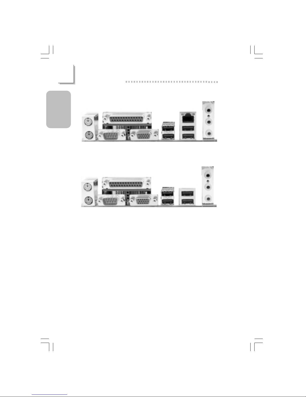
1.3 Rear Panel I/O Ports
PS/2
K/B
ATX Double Deck Ports on NS36-TL
PS/2
Mouse
Parallel
RJ45
LAN
USB 4/3COM 1
VGA
Line-out
Line-in
Mic-in
USB 1
USB 2
PS/2
Mouse
Parallel
USB 1
USB 2
USB 3
USB 4
Line-out
Line-in
Mic-in
PS/2
K/B
COM 1 VGA
ATX Double Deck Ports on NS36-TC
63000232 1.pmd 9/13/02, 1:36 PM10
11
1
Quick Setup Guide
Quick Setup
Guide
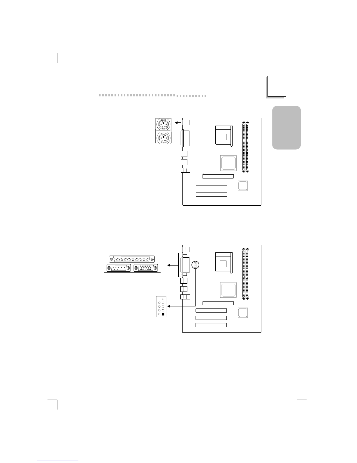
1.3.1 PS/2 Mouse and PS/2 Keyboard Ports
PS/2 Mouse
PS/2 Keyboard
1.3.2 Serial Port
J2
Make sure to turn off your computer prior to connecting or disconnecting
a mouse or keyboard. Failure to do so may damage the system board.
J4
COM 2
(J6)
2
1
9
COM 1
Serial Port
63000232 1.pmd 9/13/02, 1:36 PM11

12
Quick Setup Guide
1
Quick Setup
Guide
1.3.4 VGA Por t
VGA Por t
1.3.3 Parallel Port
Parallel Port
J5
J7
63000232 1.pmd 9/13/02, 1:36 PM12
13
1
Quick Setup Guide
Quick Setup
Guide
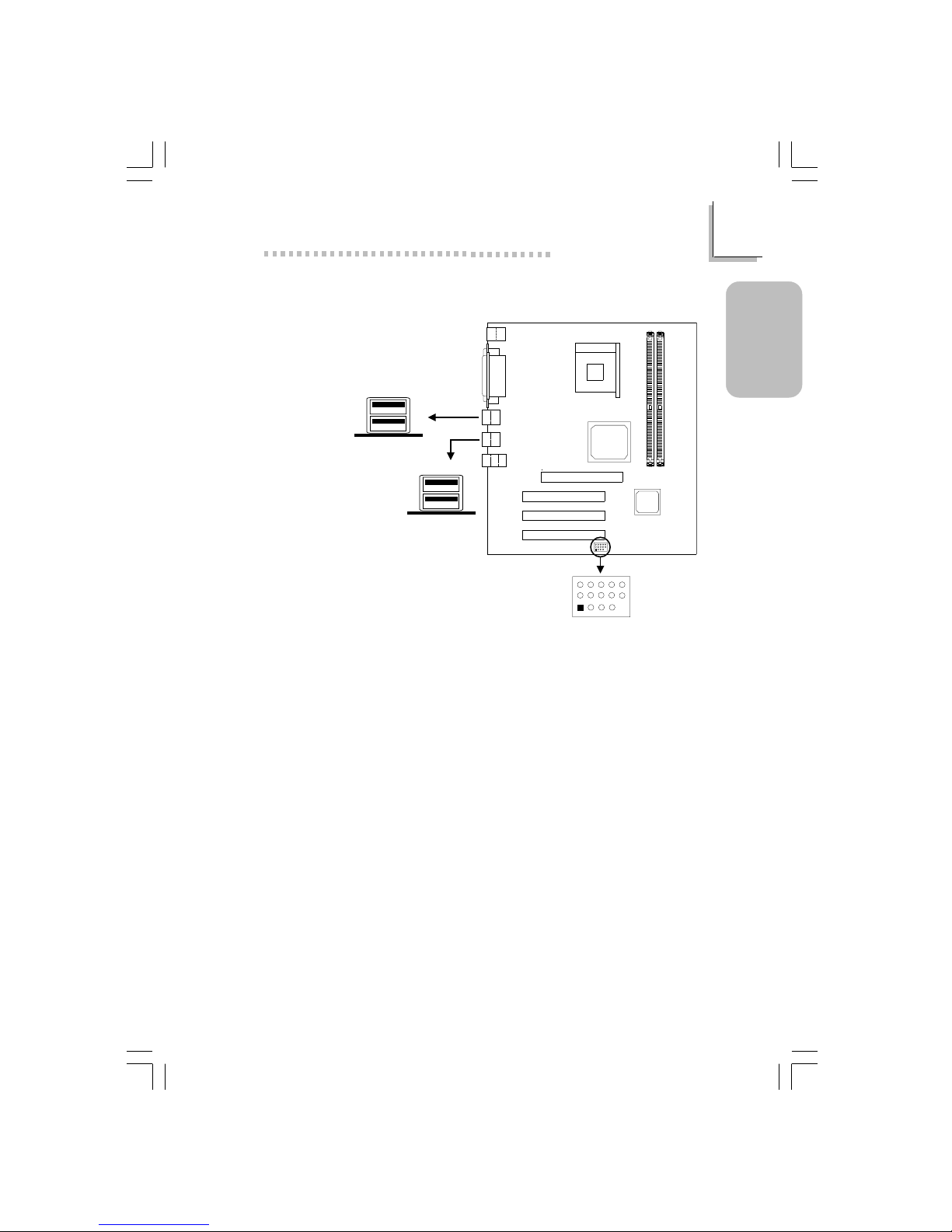
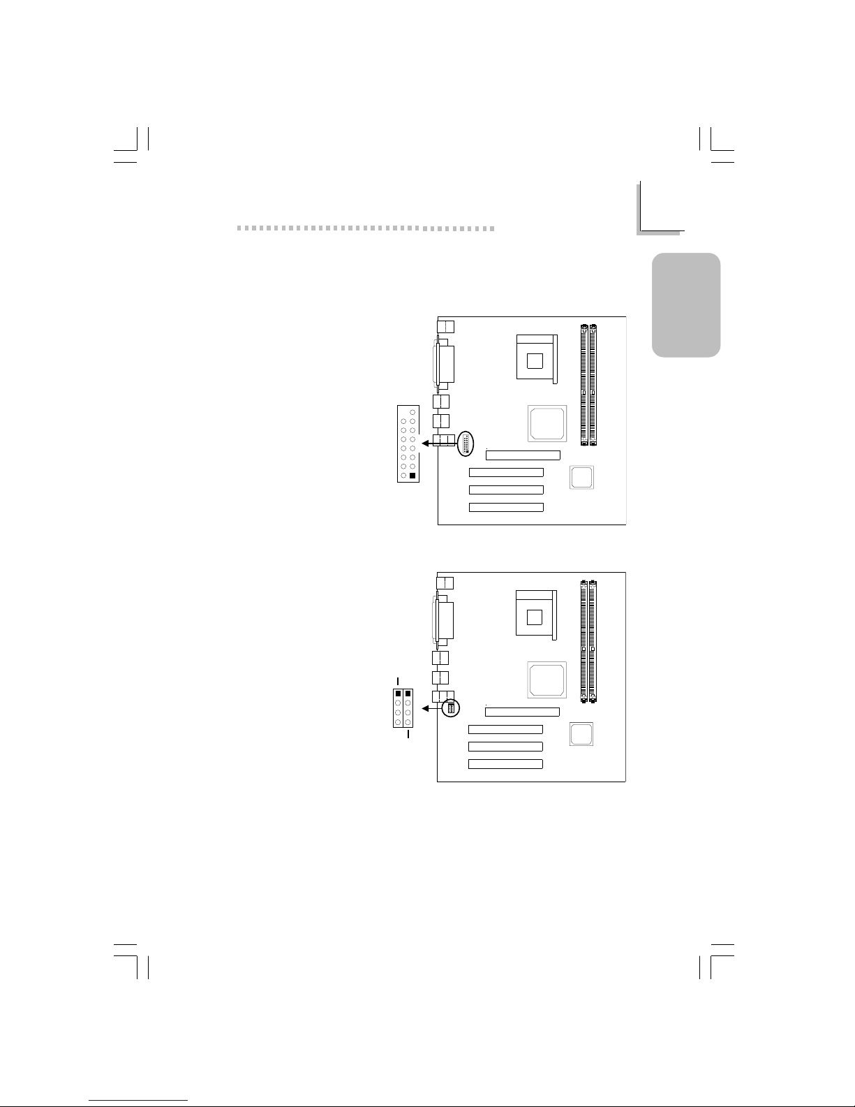
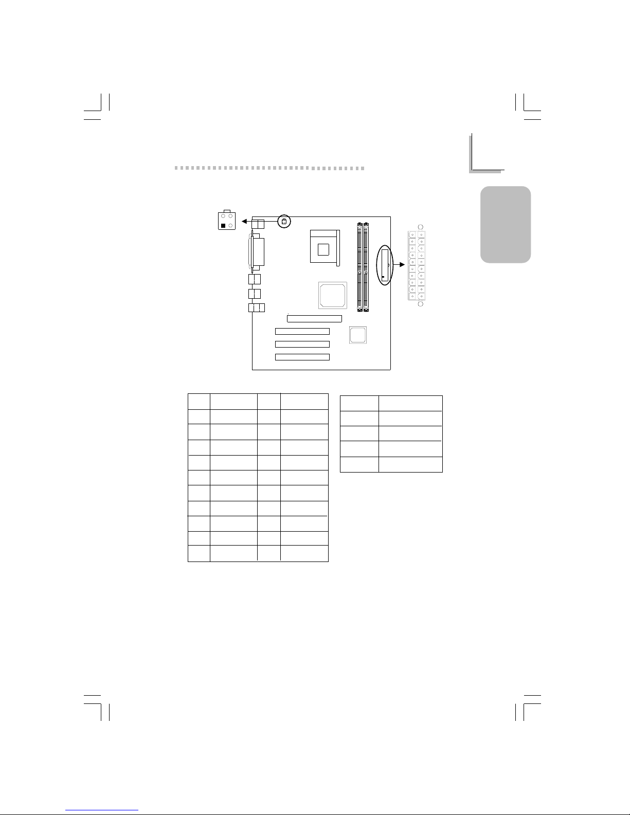
1.3.5 Universal Serial Bus Ports
Additional USB Ports (USB 5 and USB 6)
1 VCC 6 VCC 11 Ground
2 UP5- 7 UP6- 12 Ground
3 UP5+ 8 UP6+ 13 UP5+
4 Ground 9 Gruond 14 UP5-
5 Key 10 N. C. 15 VCC
CN1
J3
USB5&6(J25)
5
15
11
1
USB 2
USB 1
USB 4
USB 3
63000232 1.pmd 9/13/02, 1:36 PM13
14
Quick Setup Guide
1
Quick Setup
Guide
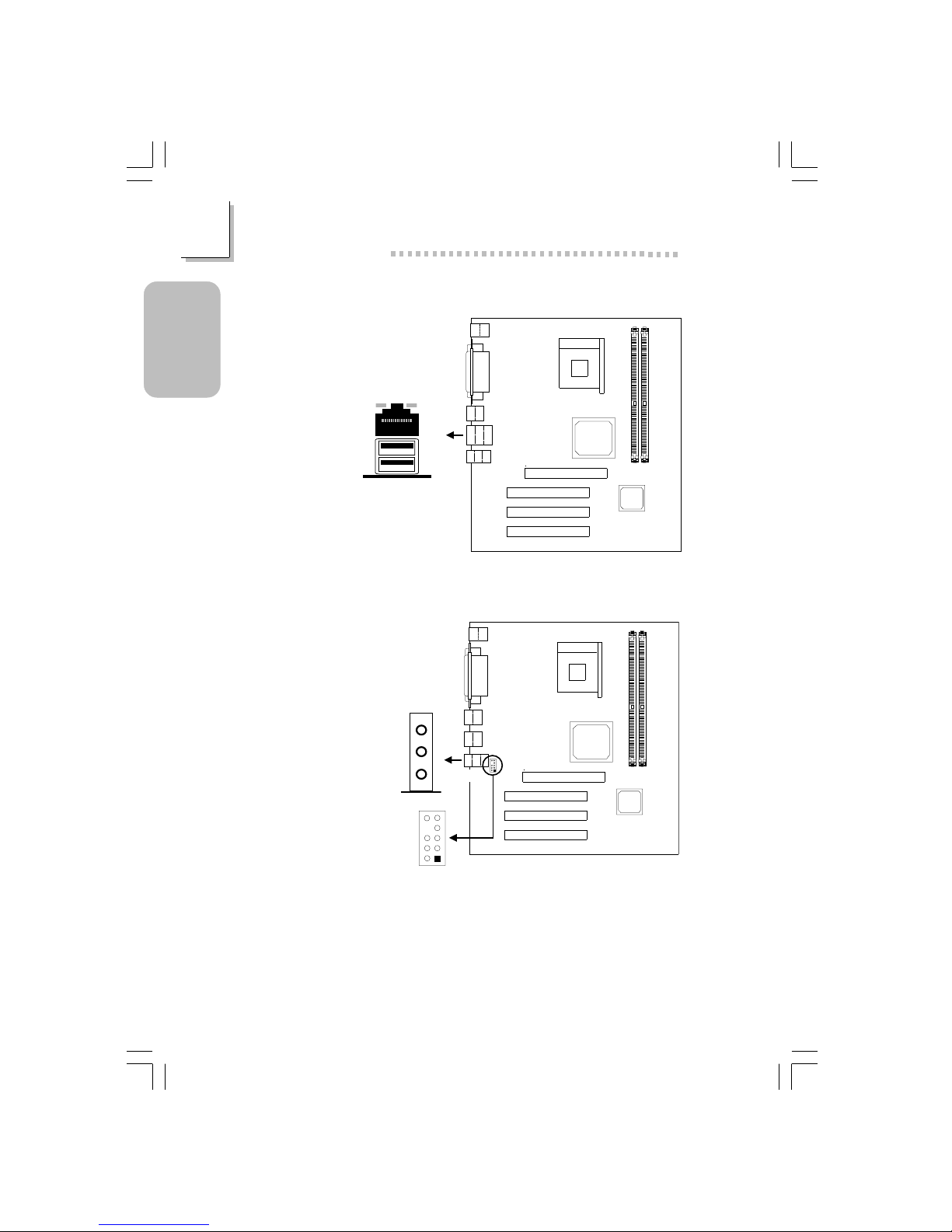
1.3.6 RJ45 Fast-Ethernet Port (NS36-TL only)
RJ45 LAN
1.3.7 Audio Jacks
1 Mic+
2 Ground
3 N.C .
4 AuD_Vcc (A vcc)
5 AuD_R_Out
6 N.C .
7 N.C .
8 Key
9 AuD_L_Out
10 N.C .
J3
Front Audio (J10)
CN3
Front audio
(J10)
10
9
2
1
Line-out
Line-in
Mic-in
63000232 1.pmd 9/13/02, 1:36 PM14
15
1
Quick Setup Guide
Quick Setup
Guide
1.4 I/O Connectors
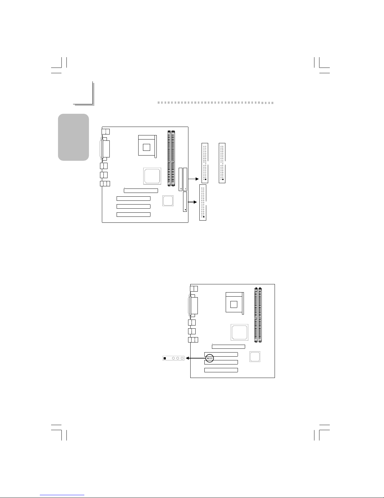
1.4.1 Game/MIDI Port
1.4.2 Internal Audio Connectors
1 Left audio channel
2 Ground
3 Ground
4 Right audio channel
CD-in / AUX-in
Game/MIDI
(J13)
2
15
1
CD-in
(J16)
AUX-in
(J15)
1
2
3
4
63000232 1.pmd 9/13/02, 1:36 PM15
16
Quick Setup Guide
1
Quick Setup
Guide
1.4.4 IrDA Connector
1 VCC
2 Key
3 IRRX
4 Ground
5 IRTX
1.4.3 Floppy and IDE Disk Drive Connectors
If you encountered problems while using an ATAPI CD-ROM drive that is
set in Master mode, please set the CD-ROM drive to Slave mode. Some
ATAPI CD-ROMs may not be recognized and cannot be used if
incorrectly set in Master mode.
Primary
IDE (J18)
Secondary
IDE (J17)
1
2
40
39
1
2
40
39
FDD (J22)
1
2
33
34
IrDA (J20)
1234
5
63000232 1.pmd 9/13/02, 1:36 PM16
17
1
Quick Setup Guide
Quick Setup
Guide
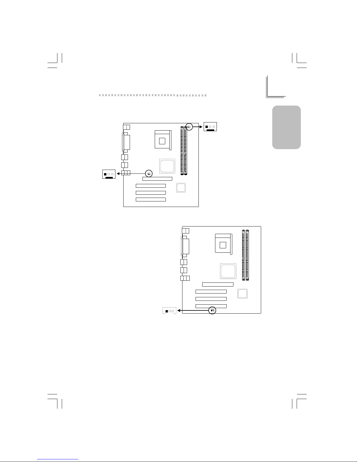
1.4.5 Fan Connectors
1 Ground
2 Power
3 Sense
1 Ground
2 Power
3 Sense
CPU Fan
System Fan
1.4.6 Wake-On-LAN Connector
The 5VSB power source of your power supply must support ≥720mA.
1 +5VSB
2 Ground
3 WOL
System fan
(J12)
3
2
1
CPU fan
(J1)
3
2
1
Wake-On-LAN
(J23)
3
21
63000232 1.pmd 9/13/02, 1:36 PM17
18
Quick Setup Guide
1
Quick Setup
Guide
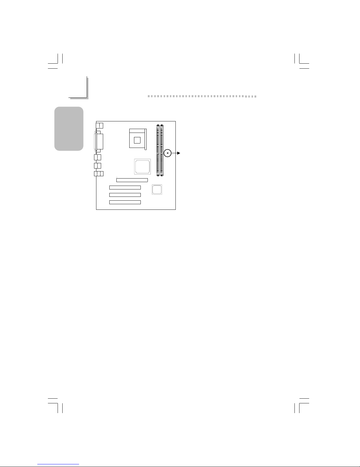
Lighted LEDs serve as a reminder that you must power-off the system
then turn off the power supply’s switch or unplug the power cord prior to
installing any memory modules or add-in cards.
1.4.7 DIMM Standby Power LED
DIMM standby
power LED
63000232 1.pmd 9/13/02, 1:36 PM18
19
1
Quick Setup Guide
Quick Setup
Guide
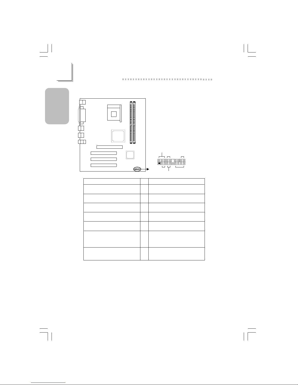
1.4.8 Power Connector
ATX Power
(J8)
+12V power
(ATXP1)
3
4
1
2
2
1
3
4
1
10
11
20
Pin
1
2
3
4
5
6
7
8
9
10
Function
3.3V
3.3V
Ground
+5V
Ground
+5V
Ground
PW-OK
5VSB
+12V
Pin
11
12
13
14
15
16
17
18
19
20
Function
3.3V
-12V
Ground
PS-ON
Ground
Ground
Ground
-5V
+5V
+5V
ATX Main Power Connector
Pin
1
2
3
4
Function
Ground
Ground
+12V
+12V
+12V Power Connector
63000232 1.pmd 9/13/02, 1:36 PM19
20
Quick Setup Guide
1
Quick Setup
Guide
1.4.9 Front Panel Connectors
If a system did not boot-up and the Power/Standby LED did not light
after it was powered-on, it may indicate that the CPU or memor y module
was not installed properly. Please make sure they are properly inser ted
into their corresponding socket.
PWR-LED
HD-LED
ATX-SW
G-SW
RESET
SPEAKER
2
1
20
19
Pin
3
5
14
16
8
10
18
20
7
9
13
15
17
19
2
4
6
HD-LED
(Primary/Secondary IDE LED)
Reserved
ATX-SW
(ATX power switch)
G-SW
(Green switch)
RESET
(Reset switch)
SPEAKER
(Speaker connector)
PWR-LED
(Power/Standby LED)
Pin Assignment
HDD LED Power
HDD
N. C.
N. C.
PWRBT+
PWRBT-
Ground
Green switch
Ground
H/W Reset
Speaker Data
N. C.
Ground
Speaker Power
LED Power (+)
LED Power (+)
LED Power (-) or Standby Signal
63000232 1.pmd 9/13/02, 1:36 PM20

21
1
Quick Setup Guide
Quick Setup
Guide
1.5 Award BIOS Setup Utility
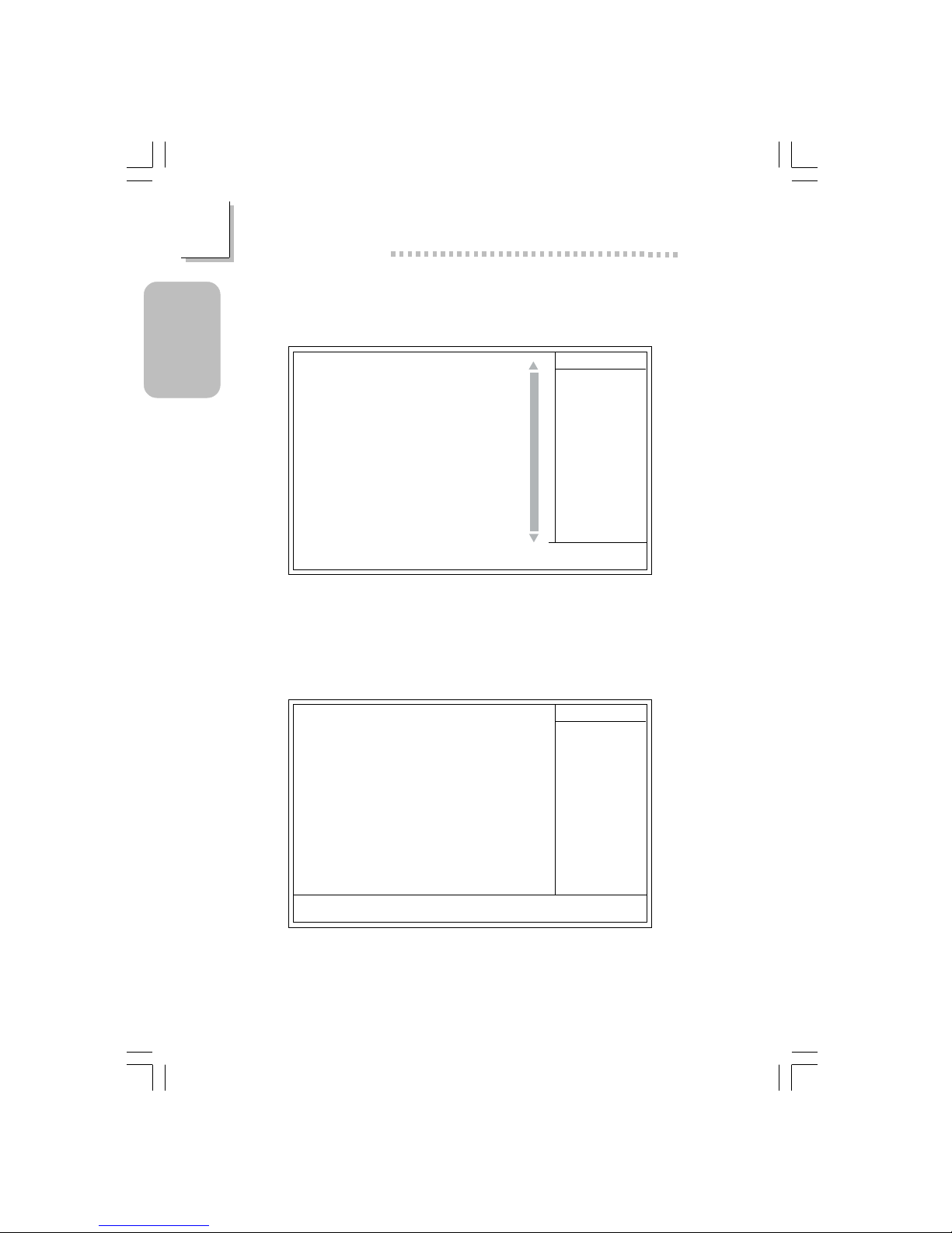
1.5.1 Main Menu
1.5.2 Standard CMOS Features
Phoenix - AwardBIOS CMOS Setup Utility
Standard CMOS Features
Advanced BIOS Features
Advanced Chipset Features
Integrated Peripherals
Power Management Setup
PnP/PCI Configurations
PC Health Status
Frequency/Voltage Control
Load Fail-Safe Defaults
Load Optimized Defaults
Set Supervisor Password
Set User Password
Save & Exit Setup
Exit Without Saving
Esc
F10
: Quit
: Save & Exit Setup
↑↓→←
: Select Item
Time, Date, Hard Disk Type...
The settings on the screen are for reference only. Your version may not be
identical to this one.
↑↓→← :Move
Phoenix - AwardBIOS CMOS Setup Utility
Standard CMOS Features
Date (mm:dd:yy)
Time (hh:mm:ss)
IDE Primary Master
IDE Primary Slave
IDE Secondary Master
IDE Secondary Slave
Drive A
Drive B
Video
Halt On
Base Memory
Extended Memory
Total Memory
F6:Fail-Safe Defaults F7:Optimized Defaults
F1:General Help
Mon, Jun 24 2002
4 : 35 : 5
Press Enter None
Press Enter None
Press Enter None
Press Enter None
1.44M, 3.5 in.
None
EGA/VGA
All, But Keyboard
640K
129024K
130048K
Item Help
Menu Level
Change the day, month,
year and century
Enter:Select
F5:Previous Values
+/-/PU/PD:Value
F10:Save
ESC:Exit
!
!
!
!
63000232 1.pmd 9/13/02, 1:36 PM21
22
Quick Setup Guide
1
Quick Setup
Guide
1.5.4 Advanced Chipset Features
1.5.3 Advanced BIOS Features
Phoenix - AwardBIOS CMOS Setup Utility
Advanced BIOS Features
Item Help
Menu Level
Allows you to choose
the VIRUS warning
feature for IDE Hard
Disk boot sector
protection. If this
function is enabled and
someone attempt to
write data into this
area, BIOS will show a
warning message on
screen and alarm beep
↑↓→← Move F1:General HelpEnter:Select +/-/PU/PD:Value F10:Save ESC:Exit
X
X
F6:Fail-Safe Defaults F7:Optimized DefaultsF5:Previous Values
The screen above list all the fields available in the Advanced BIOS Features
submenu, for ease of reference in this manual. In the actual CMOS setup,
you have to use the scroll bar to view the fields. The settings on the screen
are for reference only. Your ver sion may not be identical to this one.
Virus Warning
CPU L1 & L2 Cache
Quick Power On Self Test
First Boot Device
Second Boot Device
Third Boot Device
Boot Other Device
Swap Floppy Drive
Boot Up Floppy Seek
Boot Up NumLock Status
Typematic Rate Setting
Typematic Rate (Chars/Sec)
Typematic Delay (Msec)
Security Option
APIC Mode
MPS Version Control For OS
OS Select For DRAM > 64MB
HDD S.M.A.R.T. Capability
Report No FDD For WIN95
Full Screen LOGO Show
Onboard LAN Boot ROM
Disabled
Enabled
Fast
Floppy
HDD-0
LS120
Enabled
Disabled
Disabled
On
Disabled
6
250
Setup
Enabled
1.4
Non-OS2
Disabled
No
Enabled
Disabled
Phoenix - AwardBIOS CMOS Setup Utility
Advanced Chipset Features
The settings on the screen are for reference only. Your version may not be
identical to this one.
Item Help
Menu Level
↑↓→← Move
F6:Fail-Safe Defaults F7:Optimized Defaults
F1:General HelpEnter:Select
F5:Previous Values
+/-/PU/PD:Value
F10:Save
ESC:Exit
DRAM Clock/Drive Control
Prefetch Caching
AGP Aperture Size
AGP Fast Write
AGP SideBand Address
AGP Capability
System Share Memory Size
Press Enter
Disabled
64MB
Disabled
Disabled
Auto
32 MB
!
63000232 1.pmd 9/13/02, 1:36 PM22

23
1
Quick Setup Guide
Quick Setup
Guide
1.5.5 Integrated Peripherals
1.5.6 Power Management Setup
Phoenix - AwardBIOS CMOS Setup Utility
Integrated Peripherals
Item Help
Menu Level
↑↓→← Move
F6:Fail-Safe Defaults F7:Optimized Defaults
F1:General HelpEnter:Select
F5:Previous Values
+/-/PU/PD:Value
F10:Save
ESC:Exit
SIS OnChip IDE Device
SIS OnChip PCI Device
Onboard Super IO Device
IDE HDD Block Mode
Init Display First
AGP Auto Calibration
Press Enter
Press Enter
Press Enter
Disabled
PCI Slot
Enabled
!
!
!
The settings on the screen are for reference only. Your ver sion may not be
identical to this one.
The settings on the screen are for reference only. Your version may not be
identical to this one.
Phoenix - AwardBIOS CMOS Setup Utility
Power Management Setup
ACPI Function
ACPI Suspend Type
Power Management
Suspend Mode
Video Off Option
Video Off Method
Switch Function
MODEM Use IRQ
Hot Key Function As
HDD Power Down
Soft-Off By PWRBTN
PWR Lost Resume State
PM Wake Up Events
Enabled
S1(POS)
User Define
Disabled
Suspend -> Off
V/H SYNC+Blank
Break/W ake
Auto
Power Off
Disable
Instant-off
Keep Off
Press Enter
Item Help
Menu Level
↑↓→← Move
F6:Fail-Safe Defaults F7:Optimized Defaults
F1:General HelpEnter:Select
F5:Previous Values
+/-/PU/PD:Value F10:Save ESC:Exit
!
63000232 1.pmd 9/13/02, 1:36 PM23

24
Quick Setup Guide
1
Quick Setup
Guide
1.5.7 PnP/PCI Configurations
1.5.8 PC Health Status
The settings on the screen are for reference only. Your version may not be
identical to this one.
X
Phoenix - AwardBIOS CMOS Setup Utility
PnP/PCI Configurations
Reset Configuration Data
Resources Controlled By
IRQ Resources
PCI/VGA Palette Snoop
Disabled
Auto(ESCD)
Press Enter
Disabled
Item Help
Menu Level
Default is Disabled.
Select Enabled to
reset Extended System
Configuration Data
(ESCD) when you exit
Setup if you have
installed a new add-on
and the system
reconfiguration has
caused such a serious
conflict that the OS
cannot boot.
↑↓→← Move
F6:Fail-Safe Defaults F7:Optimized Defaults
F1:General HelpEnter:Select
F5:Previous Values
+/-/PU/PD:Value
F10:Save
ESC:Exit
The settings on the screen are for reference only. Your version may not be
identical to this one.
Phoenix - AwardBIOS CMOS Setup Utility
PC Health Status
Current System Temp.
Current CPU Temperature
Current CPU FAN Speed
Current System FAN Speed
CPU(V)
+3.3
+5
+12
-12
VBAT(V)
5VSB(V)
27C/80F
37C/98F
0 RPM
0 RPM
Item Help
Menu Level
↑↓→← Move
F6:Fail-Safe Defaults F7:Optimized Defaults
F1:General HelpEnter:Select
F5:Previous Values
+/-/PU/PD:Value F10:Save ESC:Exit
1.75 V
3.35 V
4.90 V
11.85 V
-11.45 V
3.24 V
5.37 V
V
V
V
V
63000232 1.pmd 9/13/02, 1:36 PM24

25
1
Quick Setup Guide
Quick Setup
Guide
1.5.9 Frequency/Voltage Control
The settings on the screen are for reference only. Your version may not be
identical to this one.
Phoenix - AwardBIOS CMOS Setup Utility
Frequency/Voltage Control
CPU Clock Ratio
Auto Detect DIMM/PCI Clk
Spread Spectrum Modulated
CPU Host/SDRAM/PCI Clock
8 X
Enabled
+/- 0.25%
Default
Item Help
Menu Level
↑↓→← Move
F6:Fail-Safe Defaults F7:Optimized Defaults
F1:General HelpEnter:Select
F5:Previous Values
+/-/PU/PD:Value
F10:Save
ESC:Exit
63000232 1.pmd 9/13/02, 1:37 PM25

26
English
2
English
Table of Contents
Chapter 2 - English
Package Checklist
The system board package contains the following items:
! The system board
! A user’s manual
! One card-edge bracket mounted with 1 serial port and 1
game/MIDI por t
! One IDE cable for ATA/33, ATA/66, ATA/100 or ATA/133 IDE
drives
! One 34-pin floppy disk drive cable
! One “Main Board Utility” CD
If any of these items are missing or damaged, please contact your
dealer or sales representative for assistance.
2.1 Features and Specifications.....................................................................................
2.2 Using the Suspend to RAM Function..........................................................
2. 3 Supported Softwares...................................................................................................
2.4 Troubleshooting.................................................................................................................
27
33
35
39
Note:
The user’s manual in the provided CD contains detailed information
about the system board. If, in some cases, some information doesn’t
match those shown in this manual, this manual should always be
regarded as the most updated version.
63000232 2.pmd 9/10/02, 4:59 PM26

27
2
English
English
2.1 Features and Specifications
2.1.1 Features
Chipset
• SiS® 651/962L
Processor
The system board is equipped with Socket 478 for installing a
Pentium® 4 or Celeron® processor.
• Intel® Pentium® 4 processor (478-pin)
- 533MHz system data bus - suppor ts up to 2.53 GHz CPU
speed
- 400MHz system data bus - supports up to 2.4 GHz CPU
speed
• Intel® Celeron® processor (478-pin)
- 400MHz system data bus - supports up to 1.7 GHz CPU
speed
System Memory
• Two 184-pin DDR DIMM sockets
• Supports 4 banks up to 2GB using PC1600 (DDR200),
PC2100 (DDR266) or PC2700 (DDR333) unbuffered DDR
SDRAM DIMM, 2.5V type
• 16Mb, 64Mb, 128Mb, 256Mb and 512Mb SDRAM technology
with page size from 2KB up to 16KB
63000232 2.pmd 9/10/02, 4:59 PM27

28
English
2
English
Expansion Slots
The system board is equipped with 1 universal AGP slot, 3 PCI
slots.
AGP is an interface designed to support high performance 3D
graphics cards. It utilizes a dedicated pipeline to access system
memory for textur ing, z-buffering and alpha blending. The universal
AGP slot supports AGP 2x with up to 533MB/sec. bandwidth and
AGP 4x with up to 1066MB/sec. bandwidth for 3D graphics
applications. AGP in this system board will deliver faster and better
graphics to your PC.
Onboard Graphics Features
• SiS® 315 VGA solution integrated in SiS® 651 chip
• Integrated Real256TM 2D/3D graphics accelerator
- 2 pixel rendering pipelines and 4 texture 3D graphic engine
- Ultra-AGPIITM technology delivering AGP 4x equalent 2GB/s
bandwidth
- Advanced H/W acceleration for DVD playback
- Shared memor y size up to 64MB
Onboard Audio Features
• AC'97 2.2 extension compliant codec
• Suppor ts Microsoft® DirectSound/DirectSound 3D
• AC’97 supported with full duplex, independent sample rate
converter for audio recording and playback
Onboard LAN Features (NS36-TL only)
• Uses Phy fast ethernet controller
• Integrated IEEE 802.3 10BASE-T and 100BASE-TX compatible
PHY
• 32-bit PCI master interface
• Integrated power management functions
• Full duplex suppor t at both 10 and 100 Mbps
• Suppor ts IEEE 802.3u auto-negotiation
• Suppor ts wire for management
63000232 2.pmd 9/10/02, 4:59 PM28

29
2
English
English
Rear Panel I/O Ports (PC 99 color-coded connectors)
• Four USB 2.0/1.1 por ts
• One RJ45 LAN por t (NS36-TL only)
• One NS16C550A-compatible DB-9 serial por t
• One DB-15 VGA port
• One DB-25 parallel por t
• One mini-DIN-6 PS/2 mouse por t
• One mini-DIN-6 PS/2 keyboard port
• Three audio jacks: line-out, line-in and mic-in
I/O Connectors
• One connector for 2 additional external USB 2.0/1.1 ports
• One 9-pin connector for 1 external serial port
• One connector for an external game/MIDI por t
• One connector for external line-out and mic-in jacks
• Two internal audio connectors (AUX-in and CD-in)
• One connector for IrDA interface
• Two IDE connector s
• One floppy drive interface supports up to two 2.88MB floppy
drives
• Two ATX power supply connectors
• One Wake-On-LAN connector
• CPU fan and system fan connectors
PCI Bus Master IDE Controller
• Two PCI IDE interfaces support up to four IDE devices
• Supports ATA/33, ATA/66,ATA/100 and ATA/133 hard drives
• UDMA Modes 3, 4, 5 and 6 Enhanced IDE (data transfer rate
up to 133MB/sec.)
• Bus mastering reduces CPU utilization during disk transfer
• Suppor ts ATAPI CD-ROM, LS-120 and ZIP
IrDA Interface
The system board is equipped with an IrDA connector for wireless
connectivity between your computer and peripheral devices.
63000232 2.pmd 9/10/02, 4:59 PM29

30
English
2
English
USB Ports
The system board suppor ts 6 USB 2.0/1.1 ports. USB 1.1 supports
12Mb/second bandwidth while USB 2.0 supports 480Mb/second
bandwidth providing a marked improvement in device transfer
speeds between your computer and a wide range of simultaneously
accessible external Plug and Play peripherals.
BIOS
• Award BIOS, Windows® 98/2000/ME/XP Plug and Play
compatible
• Supports SCSI sequential boot-up
• Flash EPROM for easy BIOS upgrades
• Supports DMI 2.0 function
• 2Mbit flash memory
Desktop Management Interface (DMI)
The system board comes with a DMI 2.0 built into the BIOS. The
DMI utility in the BIOS automatically records various information
about your system configuration and stores these information in the
DMI pool, which is a part of the system board's Plug and Play
BIOS. DMI, along with the appropriately networked software, is
designed to make inventory, maintenance and troubleshooting of
computer systems easier. Refer to chapter 4 for instructions on using
the DMI utility.
2.1.2 System Health Monitor Functions
The system board is capable of monitoring the following “system
health” conditions.
• Monitors CPU/system temperature and overheat alarm
• Monitors CPU/3.3V/5V/±12V/VBAT/5VSB voltages and failure
alarm
• Monitors CPU/system fan speed and failure alarm
• Automatic system fan on/off control
• Read back capability that displays temperature, voltage and fan
speed
63000232 2.pmd 9/10/02, 4:59 PM30
 Loading...