

Page 1

935-CK8045-500
86510523
System Board User’s Manual
Carte Mère Manuel Pour Utilisateur
System-Platine Benutzerhandbuch
Manual del Usuario de Placas Base
Руководство ПользователяРуководство Пользователя
Руководство ПользователяРуководство Пользователя
Руководство Пользователя
Page 2

2
Quick Setup Guide
1
Quick Setup
Guide
Copyright
This publication contains information that is protected by copyright. No part of it
may be reproduced in any form or by any means or used to make any
transformation/adaptation without the prior written permission from the copyright
holders. This publication is provided for informational purposes only. The
manufacturer makes no representations or warranties with respect to the
contents or use of this manual and specifically disclaims any express or implied
warranties of merchantability or fitness for any particular purpose. The user will
assume the entire risk of the use or the results of the use of this document.
Further, the manufacturer reserves the right to revise this publication and make
changes to its contents at any time, without obligation to notify any person or
entity of such revisions or changes. © 2005. All Rights Reserved.
Trademarks
Product names or trademarks appearing in this manual are for identification
purpose only and are the properties of the respective owners.
Caution
To avoid damage to the system, use the correct AC input voltage range
..
..
.
To reduce the risk of electric shock, unplug the power cord before removing the
system chassis cover for installation or servicing. After installation or servicing,
cover the system chassis before plugging the power cord.
Battery: 1. Danger of explosion if battery incorrectly replaced. 2. Replace only
with the same or equivalent type recommend
by the manufacturer. 3. Dispose of
used batteries according to the battery manufacturer’s
instructions.
Notice
The system board and accessories in the package may not come similar to the
information stated in this manual. This may differ in accordance to the sales region
or models in which it was sold. For more information about the standard
package in your region, please contact your dealer or sales representative.
FCC and DOC Statement on Class B
This equipment has been tested and found to comply with the limits for a Class
B digital device, pursuant to Part 15 of the FCC rules. These limits are designed
to provide reasonable protection against harmful interference when the
equipment is operated in a residential installation. This equipment generates, uses
and can radiate radio frequency energy and, if not installed and used in accordance with the instruction manual, may cause harmful interference to radio
communications. However, there is no guarantee that interference will not occur
in a particular installation. If this equipment does cause harmful interference to
radio or television reception, which can be determined by turning the equipment
off and on, the user is encouraged to try to correct the interference by one or
more of the following measures:
• Reorient or relocate the receiving antenna.
• Increase the separation between the equipment and the receiver.
• Connect the equipment into an outlet on a circuit different from that to
which the receiver is connected.
• Consult the dealer or an experienced radio TV technician for help.
Notice:
1. The changes or modifications not expressly approved by the party
responsible for compliance could void the user's authority to operate the
equipment.
2. Shielded interface cables must be used in order to comply with the emission
limits.
Page 3

3
1
Quick Setup Guide
Quick Setup
Guide
Table of Contents
Chapter 1
Quick Setup Guide.............................................
Chapter 2
English......................................................................
Chapter 3
Français....................................................................
Chapter 4
Deutsch...............................................................................
Chapter 5
Español............................................................................
Chapter 6
Русский.......................................................................
4
14
17
20
23
26
The user’s manual in the provided CD contains detailed information about the system board. If, in some
cases, some information doesn’t match those shown in this manual, this manual should always be regarded as the most updated version.
Le manuel d’utilisateur dans le CD muni contient renseignement détaillé au sujet de carte de système. Si,
en quelque cas, quelque renseignement n’appareille de ce que dit dans ce manuel, ce manuel doit
toujours être considéré comme la plus nouvelle version.
Das Benutzerhandbuch in der angebotenen CD enthält detaillierte Informationen über die Hauptplatine.
Wenn in manchen Fällen manche Informationen nicht denjenigen Informationen dargestellt in diesem
Handbuch entsprechen, soll dieses Handbuch als die meist aktualisier te Ausgabe gelten.
El uso explicativo contene información detalle sobre la sistema board en el CD preparativo. Si en algún
caso, la información no es igual con el uso explicativo, necesita ver el uso explicativo, esque es más
nuevo.
В руководстве пользователя на предоставляемом CD диске содержится подробная
информация о материнской плате. Иногда напечатанное руководство может не
совпадать руководством на CD, так как последнее наиболее часто обновляется и
является самым свежим.
Page 4
4
Quick Setup Guide
1
Quick Setup
Guide
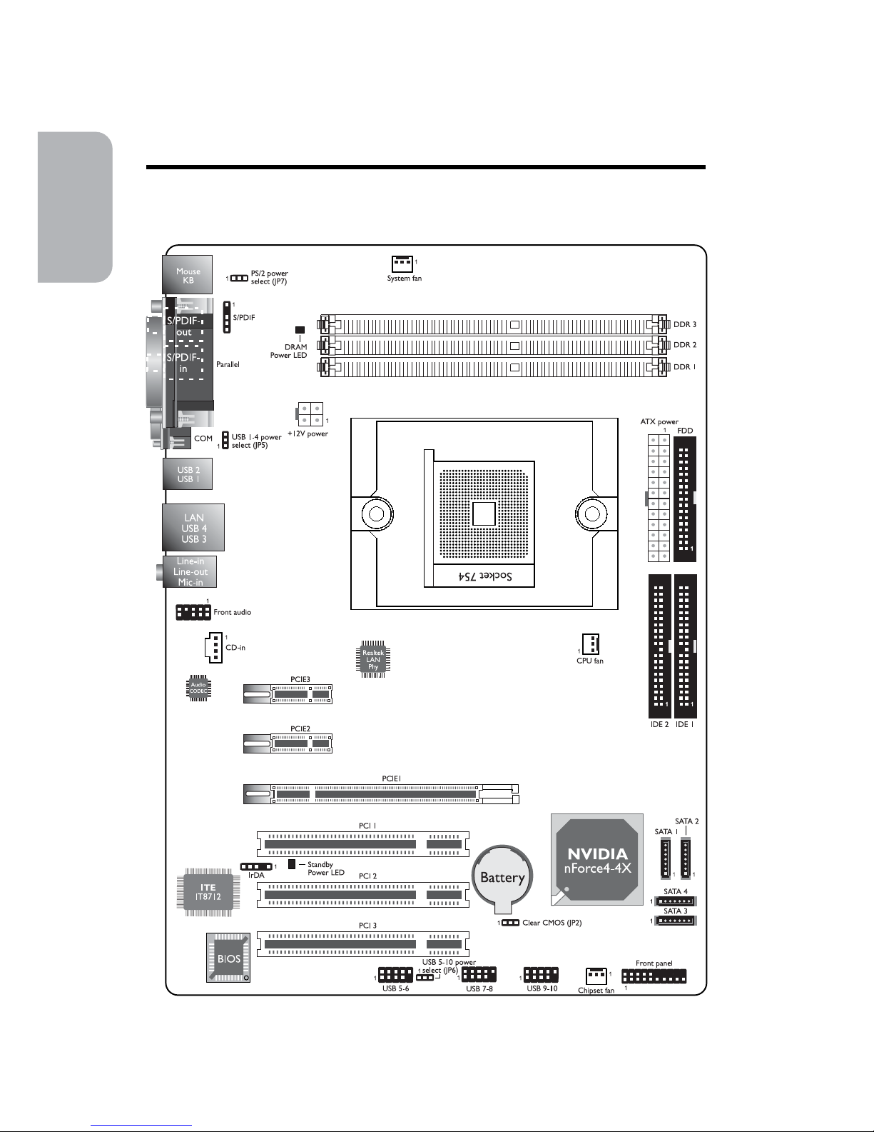
System Board Layout
Chapter 1 - Quick Setup Guide
Page 5
5
1
Quick Setup Guide
Quick Setup
Guide
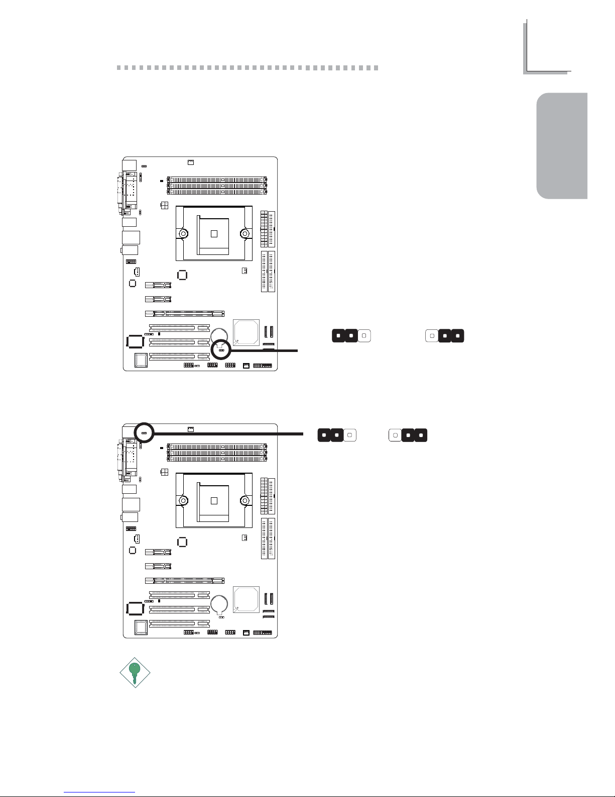
Jumpers
Important:
The 5VSB power source of your power supply must support
≥
720mA.
Clear CMOS Data
PS/2 Power Select
2-3 On:
Clear CMOS Data
1-2 On: Normal
(default)
X
JP2
312312
X
JP7
2-3 On: 5VSB
1-2 On: 5V
(default)
312312
Page 6
6
Quick Setup Guide
1
Quick Setup
Guide
Important:
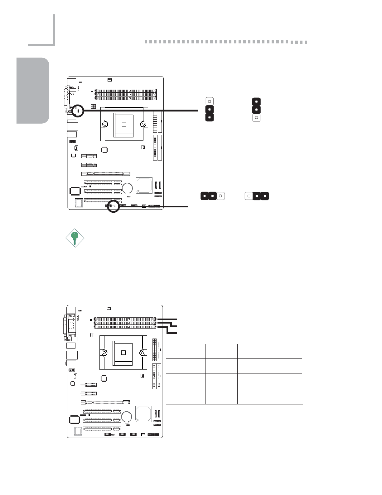
If you are using the Wake-On-USB Keyboard/Mouse function for 2
USB ports, the 5VSB power source of your power supply must
support ≥1.5A. For 3 or more USB ports, the 5VSB power source of
your power supply must support ≥2A.
USB Power Select
System Memory
DDR 3
DDR 2
DDR 1
DDR 1
1 DIMM
2 DIMMs
3 DIMMs
DDR 2
-
9
DDR 3
-
-
99
99
9
Install DIMMs according to the sequence
of the DDR socket indicated in the
illustration. In other words, if you are
installing one DIMM only, you must install it
in DDR 1 and so on. Refer to the table
above.
X
USB 1-4
(JP5)
3
1
2
3
1
2
2-3 On: 5VSB1-2 On: 5V
(default)
2-3 On: 5VSB
1-2 On: 5V
(default)
X
USB 5-10
(JP6)
312312
Page 7
7
1
Quick Setup Guide
Quick Setup
Guide
I/O Connectors
Note:
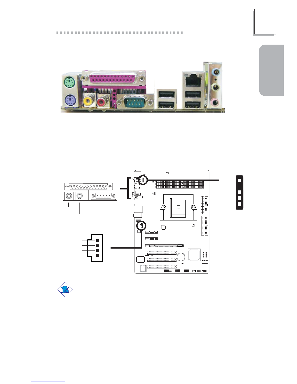
DO NOT use RCA S/PDIF and optical S/PDIF at the same time.
S/PDIF-out/in and CD-in Connectors
W
J3
1
5
+5V
Key
SPDIF out
SPDIF in
GND
S/PDIF-out
S/PDIF-in
W
W
1
4
Right audio
channel
Left audio
channel
Ground
Ground
Optical
S/PDIF
CD-in
Rear Panel I/O Ports
PS/2
Mouse
PS/2
K/B
COM
S/PDIF-out
S/PDIF-in USB 1-2 USB 3-4
LAN
Parallel
Line-out
Line-in
Mic-in
Page 8
8
Quick Setup Guide
1
Quick Setup
Guide
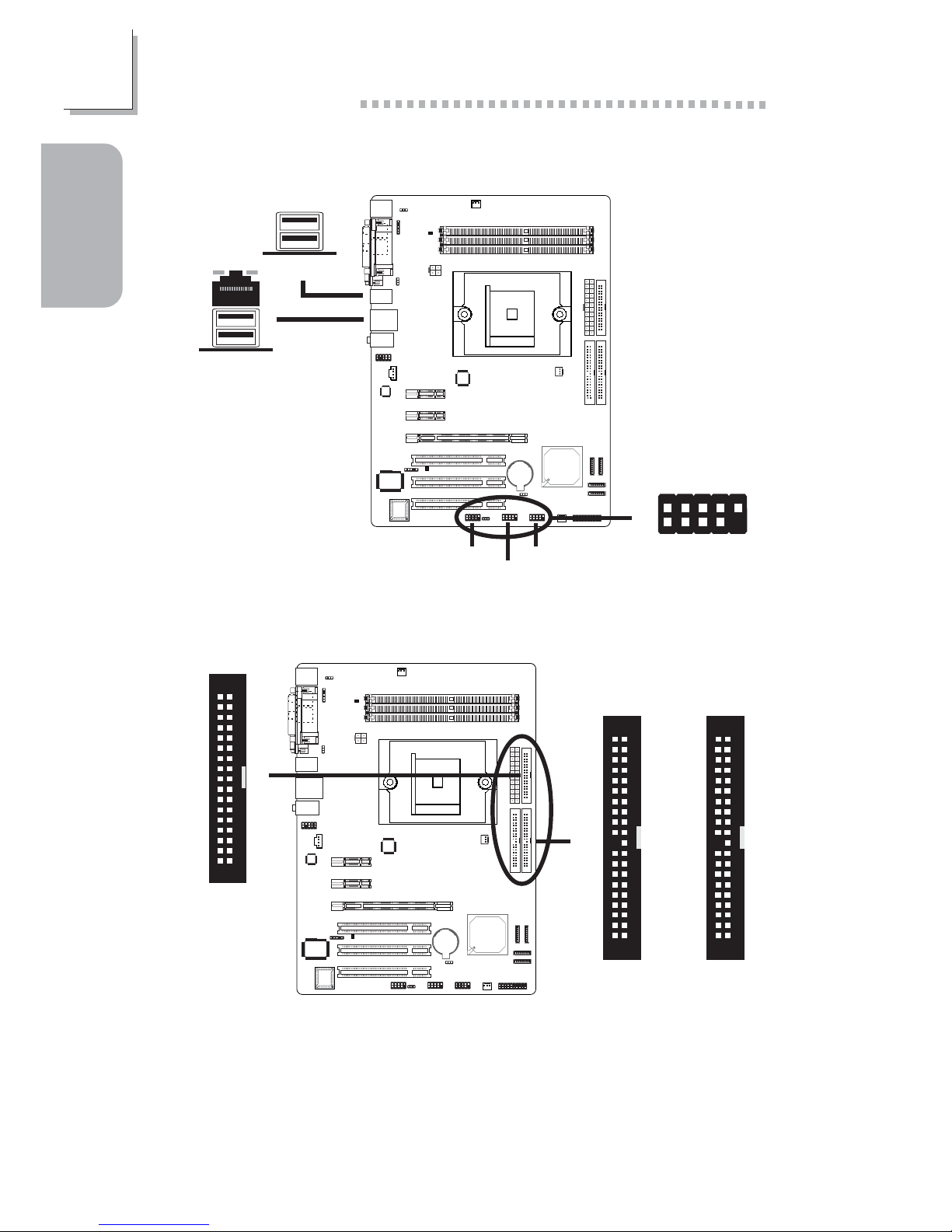
USB 4
USB 3
Universal Serial Bus Ports
W
USB 5-6
W
USB 7-8
W
USB 9-10
1
VCC
-Data
+Data
Ground
Key
VCC
-Data
+Data
Ground
N. C.
2
10
9
X
34
33
21
FDD and IDE Connectors
X
40
39
21
IDE 2
40
39
21
IDE 1
FDD
USB 2
USB 1
Page 9
9
1
Quick Setup Guide
Quick Setup
Guide
Front audio
W
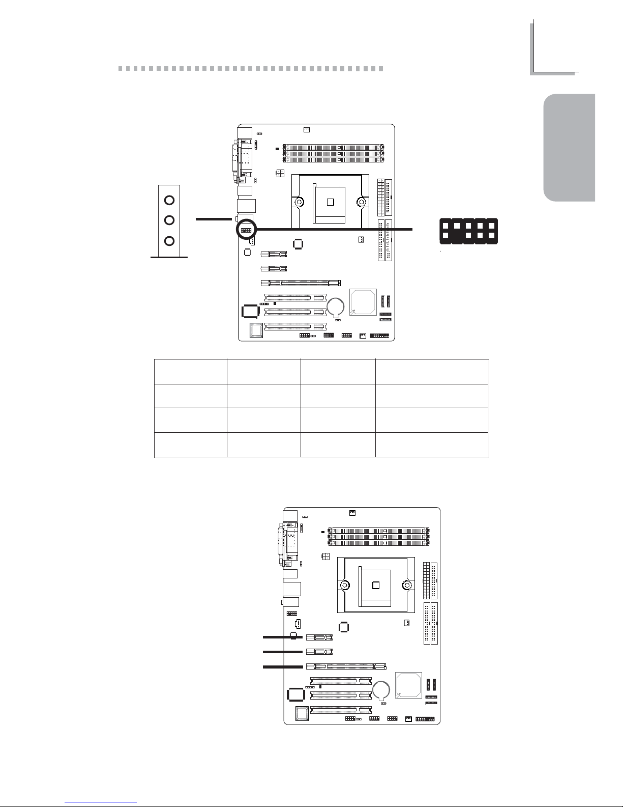
Audio (Rear Audio and Front Audio)
Mic-in
Line-out
Line-in
W
Rear audio
1
2
10
9
MicGND
Mic Power
AuD_Vcc
AuD_R_Out
AuD_R_Return
N. C.
Key
AuD_L_Out
AuD_L_Return
Light Blue
Lime
Pink
2-channel
Line-in
Line-out
Mic-in
4-channel
Rear R/L
Front R/L
Mic-in
6-channel
Rear R/L
Front R/L
Center/Subwoofer
PCI Express Slots
PCI Express x1
PCI Express x16
PCI Express x1
Page 10
10
Quick Setup Guide
1
Quick Setup
Guide
Important:
Before creating RAID, make sure you have installed the Serial/Parallel
ATA drives and connected the data cables otherwise you won’t be
able to enter the NVIDIA RAID BIOS utility.
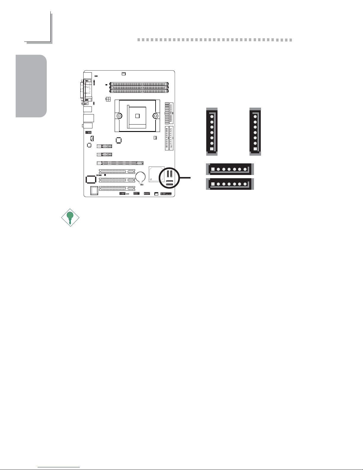
Serial ATA Connectors
X
1
7
GND
TXP
TXN
GND
RXN
RXP
GND
SATA 1
(J11)
1
7
GND
TXP
TXN
GND
RXN
RXP
GND
SATA 2
(J13)
SATA 3
(J2)
17
SATA 4
(J10)
17
Page 11
11
1
Quick Setup Guide
Quick Setup
Guide
Note:
The sequence of the pin functions on some IR cable may be
reversed from the pin function defined on the system board. Make
sure to connect the cable connector to the IR connector according to
their pin functions.
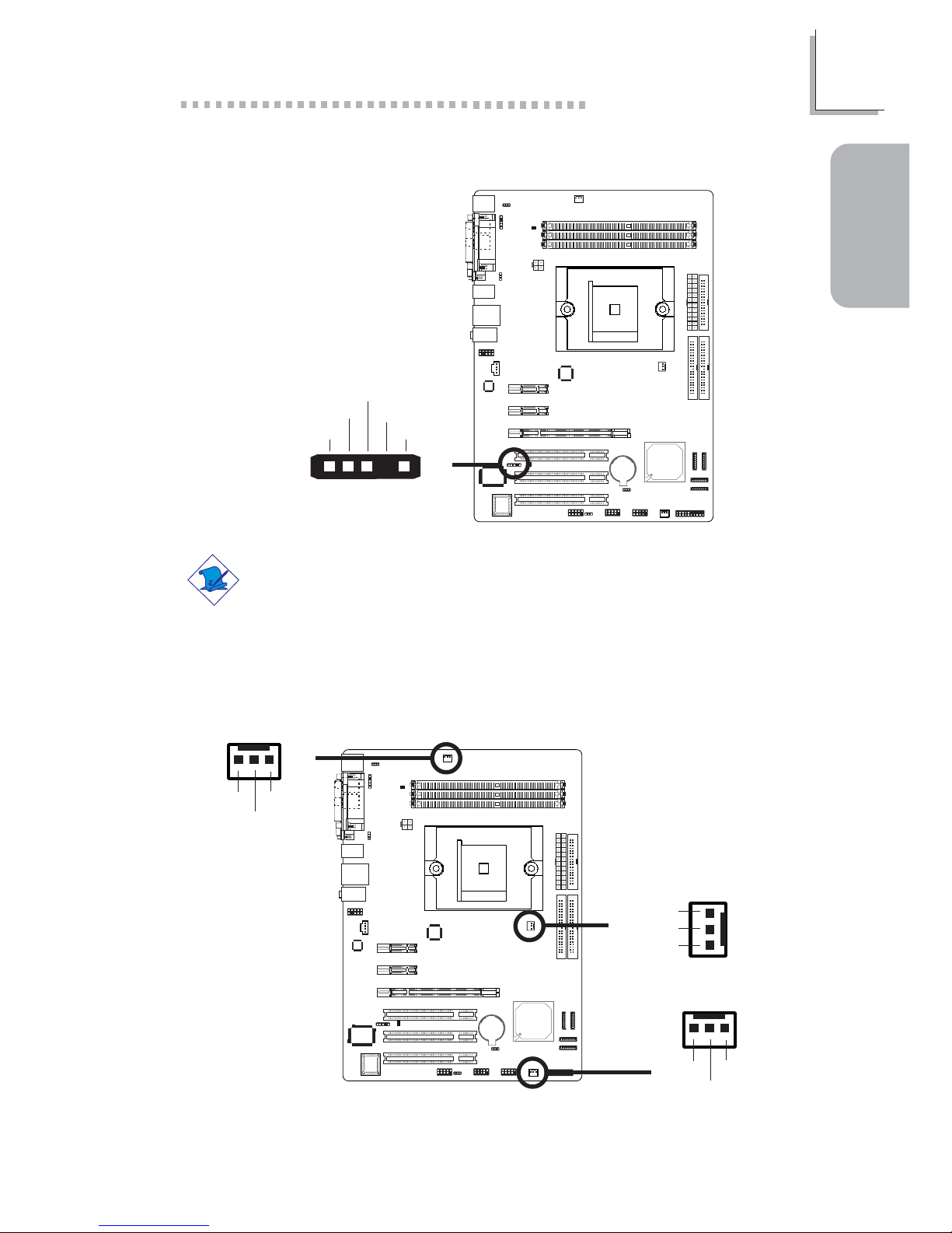
Cooling Fan Connectors
IrDA Connector
W
51
VCC
N. C.
IRRX
Ground
IRTX
X
X
X
CPU fan
1
3
Ground
Power
Sense
System fan
Chipset fan
31
Ground
Power
Sense
31
Ground
Power
Sense
Page 12
12
Quick Setup Guide
1
Quick Setup
Guide
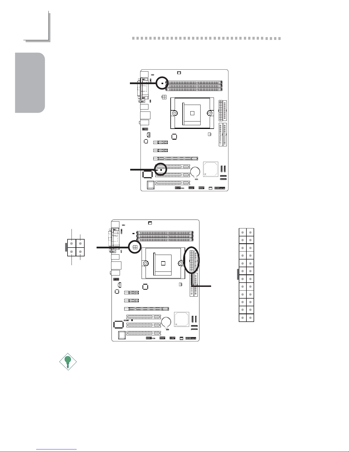
LEDs
Standby
Power LED
DRAM
Power LED
Power Connectors
X
X
4
3
1
2
+12V
Ground
Ground
+12V
13 1
1224
+3.3VDC
+3.3VDC
COM
+5VDC
COM
+5VDC
COM
PWR_OK
+5VSB
+12VDC
+12VDC
+3.3VDC
+3.3VDC
-12VDC
COM
PS_ON#
COM
COM
COM
NC
+5VDC
+5VDC
+5VDC
COM
Important:
To ensure that adequate power is provided, we strongly recommend
that you use a minimum of 400 Watt (or greater) power supply.
Page 13
13
1
Quick Setup Guide
Quick Setup
Guide
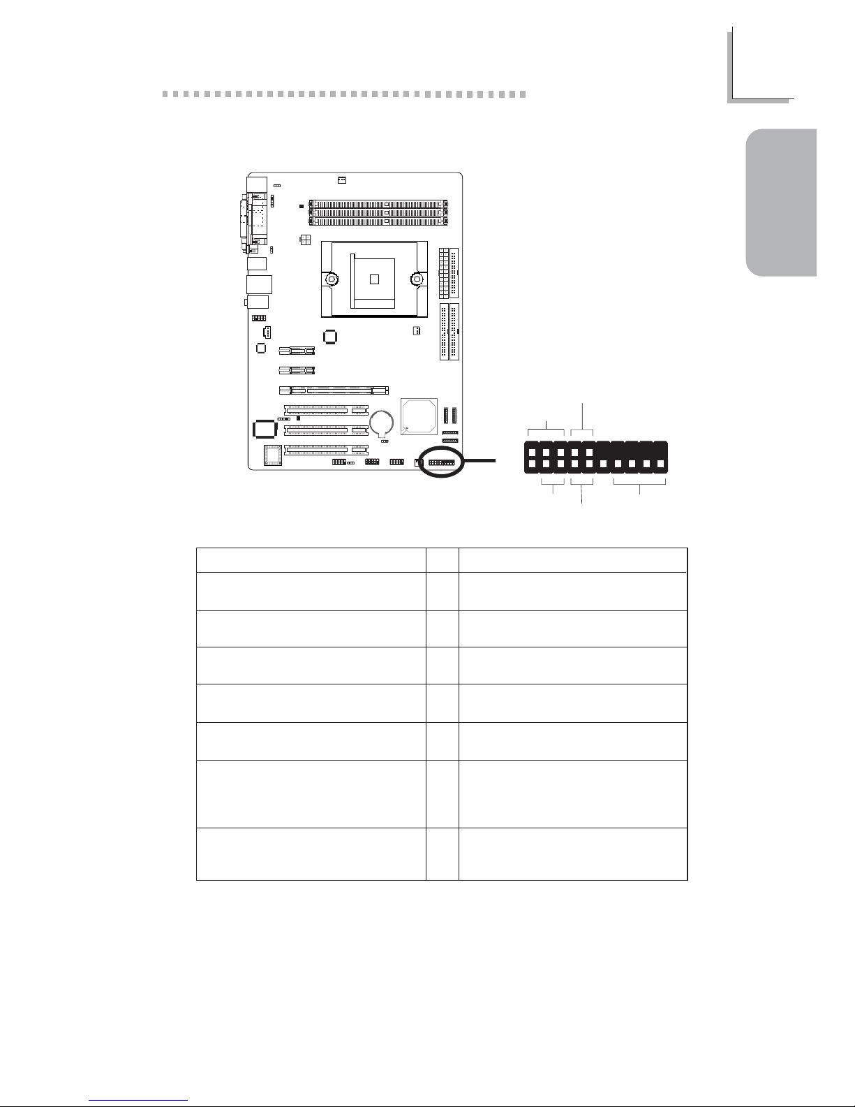
Front Panel Connectors
Pin
3
5
14
16
8
10
18
20
7
9
13
15
17
19
2
4
6
HD-LED
(Primary/Secondary IDE LED)
Reserved
ATX-SW
(ATX power switch)
Reserved
RESET
(Reset switch)
SPEAKER
(Speaker connector)
PWR-LED
(Power/Standby LED)
Pin Assignment
HDD LED Power
HDD
N. C.
N. C.
PWRBT+
PWRBT-
N. C.
N. C.
Ground
H/W Reset
Speaker Data
N. C.
Ground
Speaker Power
LED Power (+)
LED Power (+)
LED Power (-) or Standby Signal
X
J19
1
2
19
20
HD-LED
PWR-LED
ATX-SW
RESET
SPEAKER
 Loading...