

DFI NB76-TC, NB76-TL User Manual

NB76-TC
NB76-TL
Rev. A+
System Board
User’s Manual
63900232

Copyright
This publication contains information that is protected by copyright.
No part of it may be reproduced in any form or by any means or
used to make any transformation/adaptation without the prior
written permission from the copyright holders.
This publication is provided for informational purposes only. The
manufacturer makes no representations or warranties with respect to
the contents or use of this manual and specifically disclaims any
express or implied warranties of merchantability or fitness for any
particular purpose. The user will assume the entire risk of the use or
the results of the use of this document. Fur ther, the manufacturer
reserves the right to revise this publication and make changes to its
contents at any time, without obligation to notify any person or
entity of such revisions or changes.
© 2002. All Rights Reserved.
Trademarks
Windows® 98 SE, Windows® ME, Windows® 2000, Windows NT
®
4.0 and Windows® XP are registered trademarks of Microsoft
Corporation. Intel® and Pentium® 4 are registered trademarks of
Intel Corporation. Award is a registered trademark of Award
Software, Inc. Other trademarks and registered trademarks of
products appearing in this manual are the properties of their
respective holders.
Caution
To avoid damage to the system:
• Use the correct AC input voltage range.
To reduce the risk of electric shock:
• Unplug the power cord before removing the system chassis
cover for installation or servicing. After installation or servicing,
cover the system chassis before plugging the power cord.

Battery:
• Danger of explosion if battery incorrectly replaced.
• Replace only with the same or equivalent type recommend by
the manufacturer.
• Dispose of used batteries according to the battery
manufacturer’s instructions.
Joystick or MIDI port:
• Do not use any joystick or MIDI device that requires more than
10A current at 5V DC. There is a risk of fire for devices that
exceed this limit.
FCC and DOC Statement on Class B
This equipment has been tested and found to comply with the limits
for a Class B digital device, pursuant to Part 15 of the FCC rules.
These limits are designed to provide reasonable protection against
harmful interference when the equipment is operated in a residential
installation. This equipment generates, uses and can radiate radio
frequency energy and, if not installed and used in accordance with
the instruction manual, may cause harmful interference to radio
communications. However, there is no guarantee that interference
will not occur in a particular installation. If this equipment does cause
harmful interference to radio or television reception, which can be
determined by turning the equipment off and on, the user is
encouraged to tr y to correct the interference by one or more of the
following measures:
• Reorient or relocate the receiving antenna.
• Increase the separation between the equipment and the receiver.
• Connect the equipment into an outlet on a circuit different from
that to which the receiver is connected.
• Consult the dealer or an experienced radio TV technician for
help.
Notice:
1. The changes or modifications not expressly approved by the
party responsible for compliance could void the user's authority
to operate the equipment.
2. Shielded interface cables must be used in order to comply with
the emission limits.

Notice
This user’s manual contains detailed information about the system
board. If, in some cases, some information doesn’t match those
shown in the multilingual manual, the multilingual manual should
always be regarded as the most updated version. The multilingual
manual is included in the system board package.
To view the user’s manual, insert the CD into a CD-ROM drive. The
autorun screen (Main Board Utility CD) will appear. Click “User’s
Manual”.
System Board
This user’s manual is for the NB76-TC and NB76-TL system boards.
The only difference between these boards is the NB76-TL system
board supports onboard LAN.

Table of Contents
Chapter 1 - Introduction
1.1 Features and Specifications..................................................................................
1.2 Package Checklist.........................................................................................................
Chapter 2 - Hardware Installation
2.1 System Board Layout ..........................................................................................
2.2 System Memory...........................................................................................................
2.3 Jumper Settings for Clearing CMOS Data........................................
2.4 Jumper Settings for Selecting the CPU’s Front Side Bus......
2.5 Rear Panel I/O Por ts..............................................................................................
2.6 I/O Connectors...........................................................................................................
Chapter 3 - Award BIOS Setup Utility
3.1 The Basic Input/Output System.....................................................................
3.1.1 Standard CMOS Features.............................................................
3.1.2 Advanced BIOS Features..............................................................
3.1.3 Advanced Chipset Features ......................................................
3.1.4 Integrated Peripherals.........................................................................
3.1.5 Power Management Setup............................................................
3.1.6 PnP/PCI Configurations....................................................................
3.1.7 CPU Frequency Control..................................................................
3.1.8 Load Fail-Safe Defaults.....................................................................
3.1.9 Load Optimized Defaults..............................................................
3.1.10 Set Supervisor Password...............................................................
3.1.11 Set User Password..............................................................................
3.1.12 Save & Exit Setup.................................................................................
3.1.13 Exit Without Saving..............................................................................
3.2 Updating the BIOS.....................................................................................................
7
14
48
48
54
59
62
69
75
77
79
79
80
80
81
81
82
15
17
19
21
22
33

Introduction
1
6
97
97
Chapter 4 - Supported Softwares
4.1 Desktop Management Interface...................................................................
4.2 Drivers, Utilities and Software Applications.......................................
4.3 Installation Notes........................................................................................................
Appendix A - System Error Messages
A.1 POST Beep.......................................................................................................................
A.2 Error Messages..............................................................................................................
Appendix B - Troubleshooting
B.1 Troubleshooting Checklist....................................................................................
84
87
96
99

1
Introduction
7
1.1 Features and Specifications
1.1.1 Features
Chipset
• Intel® 845G chipset
- Intel® 845G Graphics Memory Controller Hub (GMCH)
- Intel® 82801DB I/O Controller Hub (ICH4)
Processor
The system board is equipped with Socket 478 for installing a
Pentium® 4 or Celeron® processor.
• Intel® Pentium® 4 processor (478-pin)
- 533MHz system data bus - suppor ts up to 2.53 GHz CPU
speed
- 400MHz system data bus - suppor ts up to 2.4 GHz CPU
speed
• Intel® Celeron® processor (478-pin)
- 400MHz system data bus - supports up to 1.8 GHz CPU
speed
System Memory
• Two 184-pin DDR SDRAM DIMM sockets
• 2.5V unbuffered PC1600 (DDR200) or PC2100 (DDR266)
DDR SDRAM DIMM
• Supports maximum of 2GB system memory using 64Mbit,
128Mbit, 256Mbit or 512Mbit technology
- Double-sided x16 DDR SDRAM DIMM is not supported
Chapter 1 - Introduction
Density Width
Single/Double
184-pin DDR
64 Mbit
X8
SS/DS
64/128MB
X16
SS/DS
32MB/NA
Density
128 Mbit
X8
SS/DS
128/256MB
X16
SS/DS
64MB/NA
256 Mbit
X8
SS/DS
256/512MB
X16
SS/DS
128MB/NA
512 Mbit
X8
SS/DS
512/1024MB
X16
SS/DS
256MB/NA

Introduction
1
8
Expansion Slots
The system board is equipped with 1 AGP/ADD slot and 6 PCI
slots.
Important:
Most PCI cards today are in “Master” mode and can be
installed anywhere between PCI slot 1 and PCI slot 5. DO NOT
install “Master” mode PCI cards onto PCI slot 6 because this
slot only supports “Slave” mode.
The AGP slot only supports 1.5V AGP 4x (1066MB/sec. bandwidth)
add-in cards. AGP is an interface designed to support high
performance 3D graphics cards for 3D graphics applications. It
handles large amounts of graphics data with the following features:
• Pipelined memory read and write operations that hide memory
access latency.
• Demultiplexing of address and data on the bus for nearly 100
percent efficiency.
The ADD slot is used for installing an ADD (AGP Digital Display)
card.
Onboard Graphics Features
• Graphics memory
- Shares 512K/1MB/8MB of the system memory in DOS
mode
- Uses Dynamic Video Memory Technology (DVMT) in
Windows mode
• Graphics controller
- Core frequency of 200MHz
- 350MHz integrated 24-bit RAMDAC
- Analog display up to 2048x1536 @ 60Hz refresh
- 3D setup and render engine - Discrete, Triangles, Strips and
fans
- Per pixel perspective corrected texture mapping
- Software DVD at 30fps, full screen
• 2D graphics features
- Optimized 256-bit BLT engine
- 32-bit alpha blended cursor

1
Introduction
9
- Programmable 3-color transparent cursor
• 3D graphics features
- 200 megapixels/sec fill rate
- Maximum 3D resolution: 1600x1200x32 @ 85Hz
- Flat and Gouraud shading
- 16- and 24-bit Z-buffering and 16- and 24-bit W-buffering
- Vertex and programmable pixel fogging and
atmospheric effects
- Double and triple render buffer
• Software drivers
- Windows® 98SE/2000/ME/XP
- Windows NT® 4.0
Onboard Audio Features
• 16-bit stereo full-duplex codec with independent variable
sampling rate
• High quality differential CD input
• True stereo line level outputs
• 2-channel audio output
Onboard LAN Features (NB76-TL only)
• Uses Realtek RTL8100 fast ethernet controller
• Integrated IEEE 802.3, 10BASE-T and 100BASE-TX compatible
PHY
• 32-bit PCI master interface
• Integrated power management functions
• Full duplex support at both 10 and 100 Mbps
• Supports IEEE 802.3u auto-negotiation
• Supports wire for management
Compatibility
• PCI 2.2 and AC ’97 compliant
• Intel AGP version 2.0

Introduction
1
10
Rear Panel I/O Ports (PC 99 color-coded connectors)
• 2 USB 2.0/1.1 ports
• 1 RJ45 LAN port (NB76-TL only)
• 1 NS16C550A-compatible DB-9 serial port
• 1 DB-15 VGA port
• 1 DB-25 parallel port
• 1 mini-DIN-6 PS/2 mouse por t
• 1 mini-DIN-6 PS/2 keyboard port
• 1 game/MIDI port
• 3 audio jacks: line-out, line-in and mic-in
I/O Connectors
• 2 connectors for 4 additional external USB 2.0/1.1 ports
• 1 connector for 1 external serial por t
• 1 CD-in internal audio connector
• 1 S/PDIF-out connector
• 1 connector for IrDA interface
• 2 IDE connectors
• 1 floppy drive interface supports up to two 2.88MB floppy
drives
• 2 ATX power supply connectors
• 1 Wake-On-LAN connector
• CPU fan, chassis fan and second fan connectors
PCI Bus Master IDE Controller
• Two PCI IDE interfaces suppor t up to four IDE devices
• Supports ATA/33, ATA/66 and ATA/100 hard drives
• PIO Mode 4 Enhanced IDE (data transfer rate up to 14MB/sec.)
• Bus mastering reduces CPU utilization during disk transfer
• Supports ATAPI CD-ROM, LS-120 and ZIP
S/PDIF
The system board is equipped with the S/PDIF (Sony/Philips Digital
Interface) digital audio interface. S/PDIF is a standard audio file
transfer format that transfers digital audio signals to a device without
having to be converted first to an analog format. This prevents the
quality of the audio signal from degrading whenever it is converted
to analog.

1
Introduction
11
IrDA Interface
The system board is equipped with an IrDA connector for wireless
connectivity between your computer and peripheral devices.
USB Ports
The system board supports USB 2.0 and USB 1.1 ports. USB 1.1
supports 12Mb/second bandwidth while USB 2.0 supports 480Mb/
second bandwidth providing a marked improvement in device
transfer speeds between your computer and a wide range of
simultaneously accessible external Plug and Play peripherals.
BIOS
• Award BIOS, Windows® 98SE/2000/ME/XP Plug and Play
compatible
• Supports SCSI sequential boot-up
• Flash EPROM for easy BIOS upgrades
• Supports DMI 2.0 function
Desktop Management Interface (DMI)
The system board comes with a DMI 2.0 built into the BIOS. The
DMI utility in the BIOS automatically records various information
about your system configuration and stores these information in the
DMI pool, which is a part of the system board's Plug and Play
BIOS. DMI, along with the appropriately networked software, is
designed to make inventory, maintenance and troubleshooting of
computer systems easier. Refer to chapter 4 for instructions on using
the DMI utility.
1.1.2 Intelligence
Dual Function Power Button
Depending on the setting in the “Soft-Off By PWR-BTTN” field of
the Power Management Setup, this switch will allow the system to
enter the Soft-Off or Suspend mode.

Introduction
1
12
Wake-On-LAN
The Wake-On-LAN function is applicable only when you are using a
LAN add-in card that has the same function. It allows the network
to remotely wake up a Soft Power Down (Soft-Off) PC. Your LAN
card must support the remote wakeup function. Refer to “Wake-OnLAN Connector” in chapter 2 and “Resume On LAN” in the Power
Management Setup section in chapter 3 for more information.
Important:
The 5VSB power source of your power supply must support
≥
720mA.
Wake-On-Keyboard
This function allows you to use the keyboard to power-on the
system. Refer to “Keyboard Power On” (“Onboard Super IO
Device” field) in the Integrated Peripherals section in chapter 3 for
more information.
Important:
• The power button will not function once a keyboard
password has been set in the “KB Power On Password”
field of the Integrated Peripherals submenu. You must type
the correct password to power-on the system. If you forgot
the password, power-off the system and remove the
battery. Wait for a few seconds and install it back before
powering-on the system.
• The 5VSB power source of your power supply must
support ≥720mA.
Wake-On-USB Keyboard
The Wake-On-USB Keyboard function allows you to use a USB
keyboard to wake up a system that is in the S3 (STR - Suspend To
RAM) state. Refer to “USB KB Wake-Up From S3” in the Power
Management Setup section in chapter 3 for more information.
Important:
• If you are using the Wake-On-USB Keyboard function for 2
USB ports, the 5VSB power source of your power supply
must support ≥1.5A.

1
Introduction
13
• If you are using the Wake-On-USB Keyboard function for 3
or more USB ports, the 5VSB power source of your power
supply must support ≥2A.
RTC Timer to Power-on the System
The RTC installed on the system board allows your system to
automatically power-on on the set date and time. Refer to “Resume
By Alarm” in the Power Management Setup section in chapter 3 for
more information.
ACPI STR
The system board is designed to meet the ACPI (Advanced
Configuration and Power Interface) specification. ACPI has energy
saving features that enables PCs to implement Power Management
and Plug-and-Play with operating systems that support OS Direct
Power Management. Currently, only Windows® 98SE/2000/ME/XP
supports the ACPI function. ACPI when enabled in the Power
Management Setup will allow you to use the Suspend to RAM
function.
With the Suspend to RAM function enabled, you can power-off the
system at once by pressing the power button or selecting “Standby”
when you shut down Windows® 98SE/2000/ME/XP without having
to go through the sometimes tiresome process of closing files,
applications and operating system. This is because the system is
capable of storing all programs and data files during the entire
operating session into RAM (Random Access Memory) when it
powers-off. The operating session will resume exactly where you left
off the next time you power-on the system.
Important:
The 5VSB power source of your power supply must support
≥
1A.

Introduction
1
14
AC Power Failure Recovery
When power returns after an AC power failure, you may choose to
either power-on the system manually, let the system power-on
automatically or return to the state where you left off before power
failure occurs. Refer to “PWR Lost Resume State” (“Onboard Super
IO Device”) in the Integrated Peripherals section in chapter 3 for
more information.
Virus Protection
Most viruses today destroy data stored in hard drives. The system
board is designed to protect the boot sector and partition table of
your hard disk drive.
1.2 Package Checklist
The system board package contains the following items:
The system board
A user’s manual
One card-edge bracket mounted with a serial port
One IDE cable for ATA/33, ATA/66 or ATA/100 IDE drives
One 34-pin floppy disk drive cable
One “Main Board Utility” CD
If any of these items are missing or damaged, please contact your
dealer or sales representative for assistance.
2
Hardware Installation
15
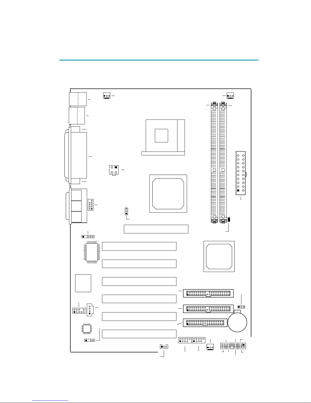
2.1 System Board Layout
Chapter 2 - Hardware Installation
NB76-TC
CN1
KB
Mouse
CN7
USB 1
USB 2
COM 1 (CN6)
Parallel (CN8)
VGA (CN2)
+12V power
(ATXP1)
4
3
2
1
CPU FSB select (JP1)
IrDA (J3)
I/O
chip
BIOS
COM 2
(J6)
2
1
9
Game/MIDI (CN9)
Line
out
(CN3)
Line
in
(CN4)
Mic
in
(CN5)
AGP Slot
PCI Slot 1
PCI Slot 2
PCI Slot 3
PCI Slot 4
PCI Slot 5
PCI Slot 6
CD-in (J5)
2
1
9
10
Front
audio (J1)
AC’97
S/PDIF-out (J4)
Wake-On-LAN
(J9)
Chassis fan
(J14)
2
1
9
10
2
1
9
10
USB 3/4
(JUSB1)
Battery
Clear CMOS
(JP2)
RESET
SPEAKER
G-SW
ATX-SW
G-LED
1
2
20
19
HD-LED
PWR-LED
J16
USB 5/6
(JUSB2)
1
FDD (J12)
IDE 2 (J11)
IDE 1 (J10)
Intel
ICH4
Intel
845G
GMCH
Socket 478
ATX
power
(PL1)
1
10
11
20
DIMM Standby
Power LED
DDR 1
DDR 2
Second fan (J15)
CPU fan (J8)
2
16
Hardware Installation
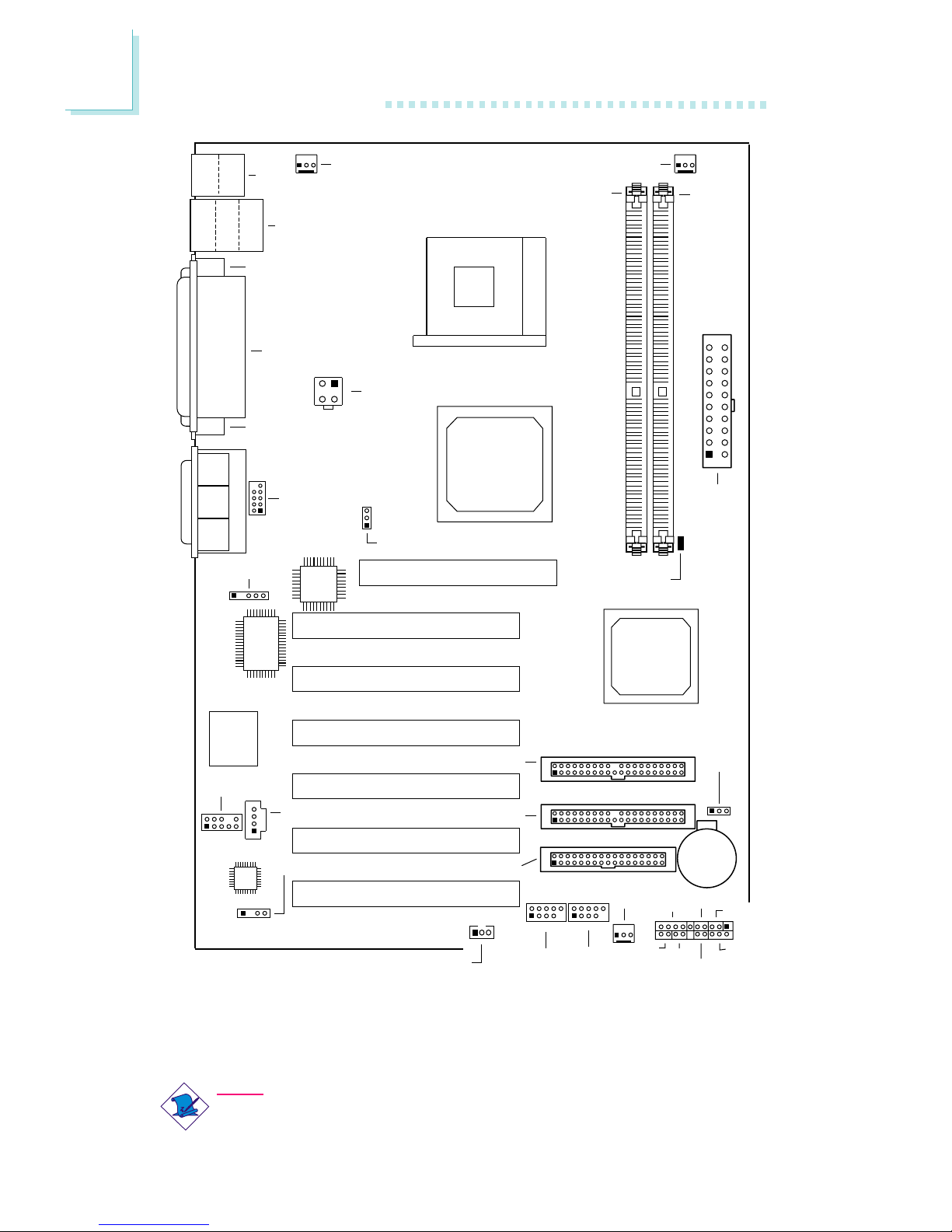
Note:
The illustrations on the following pages are based on the system
board that supports onboard LAN.
NB76-TL
(Supports onboard LAN)
CN1
KB
Mouse
CN7
LAN
USB 1
USB 2
COM 1 (CN6)
Parallel (CN8)
VGA (CN2)
+12V power
(ATXP1)
4
3
2
1
CPU FSB select (JP1)
Realtek
RTL8100
IrDA (J3)
I/O
chip
BIOS
COM 2
(J6)
2
1
9
Game/MIDI (CN9)
Line
out
(CN3)
Line
in
(CN4)
Mic
in
(CN5)
AGP Slot
PCI Slot 1
PCI Slot 2
PCI Slot 3
PCI Slot 4
PCI Slot 5
PCI Slot 6
CD-in (J5)
2
1
9
10
Front
audio (J1)
AC’97
S/PDIF-out (J4)
Wake-On-LAN
(J9)
Chassis fan
(J14)
2
1
9
10
2
1
9
10
USB 3/4
(JUSB1)
Battery
Clear CMOS
(JP2)
RESET
SPEAKER
G-SW
ATX-SW
G-LED
1
2
20
19
HD-LED
PWR-LED
J16
USB 5/6
(JUSB2)
1
FDD (J12)
IDE 2 (J11)
IDE 1 (J10)
Intel
ICH4
Intel
845G
GMCH
Socket 478
ATX
power
(PL1)
1
10
11
20
DIMM Standby
Power LED
DDR 1
DDR 2
Second fan (J15)
CPU fan (J8)
2
Hardware Installation
17
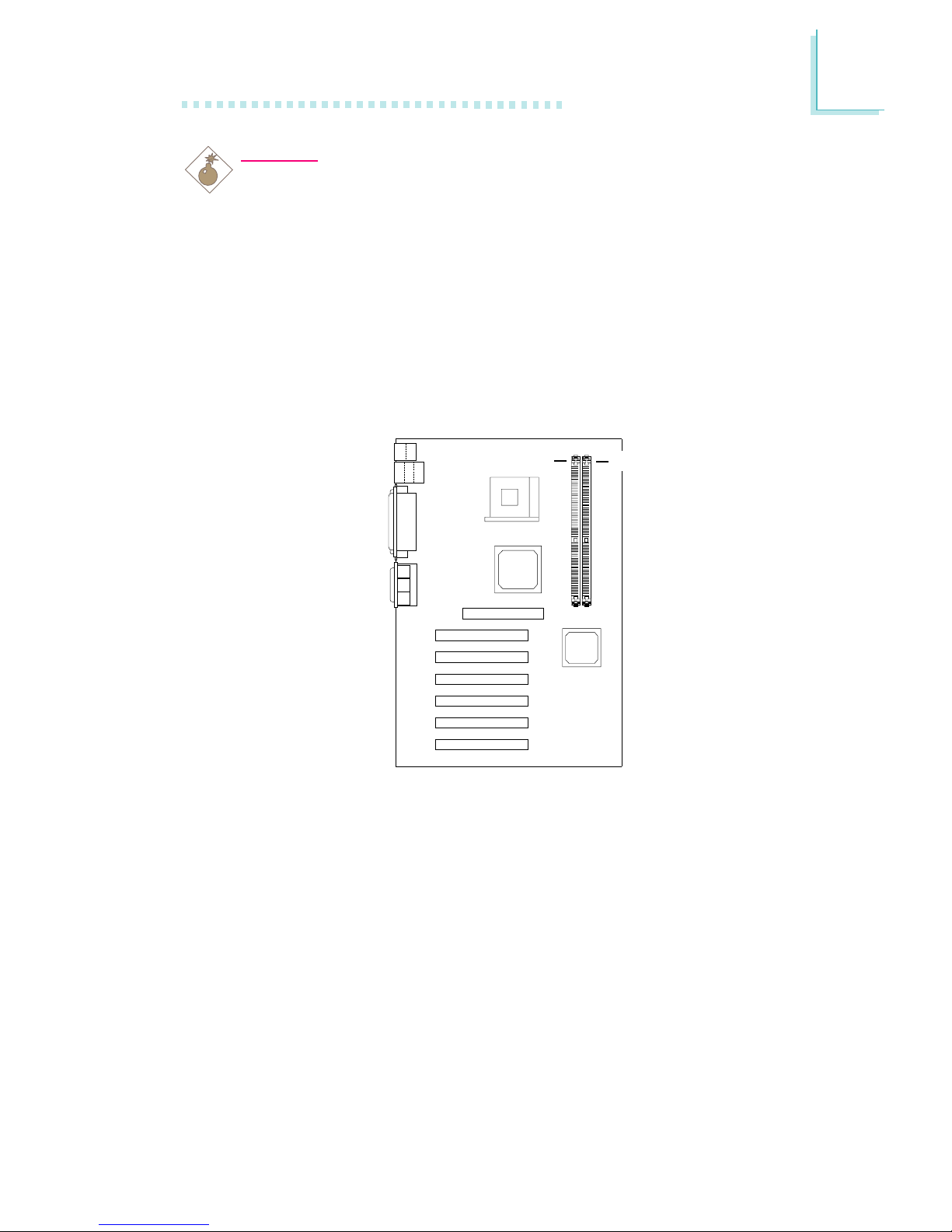
2.2 System Memory
Warning:
Electrostatic discharge (ESD) can damage your system board,
processor, disk drives, add-in boards, and other components. Perform
the upgrade instruction procedures described at an ESD workstation
only. If such a station is not available, you can provide some ESD
protection by wearing an antistatic wrist strap and attaching it to a
metal part of the system chassis. If a wrist strap is unavailable,
establish and maintain contact with the system chassis throughout
any procedures requiring ESD protection.
The system board is equipped with two 184-pin DDR SDRAM
DIMM (Dual In-line Memory Module) sockets that suppor t 2.5V
DDR SDRAM DIMM. Double Data Rate SDRAM (DDR SDRAM) is
a type of SDRAM that doubles the data rate through reading and
writing at both the rising and falling edge of each clock. This
effectively doubles the speed of operation therefore doubling the
speed of data transfer.
Refer to chapter 1 (System Memory section) for detailed
specification of the memory supported by the system board.
.
.
.
.
.
.
.
.
DDR 1
DDR 2
2
18
Hardware Installation
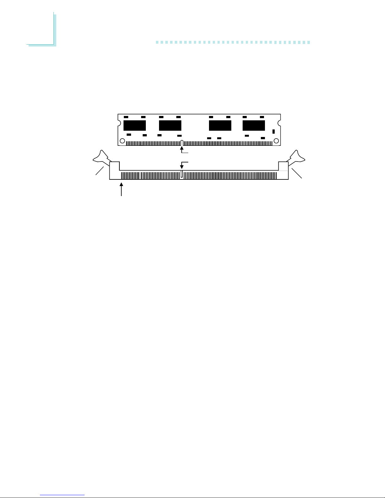
2.2.1 Installing the DIM Module
A DIM module simply snaps into a DIMM socket on the system
board. Pin 1 of the DIM module must correspond with Pin 1 of the
socket.
1. Pull the “tabs” which are at the ends of the socket to the side.
2. Position the DIMM above the socket with the “notch” in the
module aligned with the “key” on the socket.
3. Seat the module vertically into the socket. Make sure it is
completely seated. The tabs will hold the DIMM in place.
Pin 1
Notch
Key
Tab
Tab
2
Hardware Installation
19
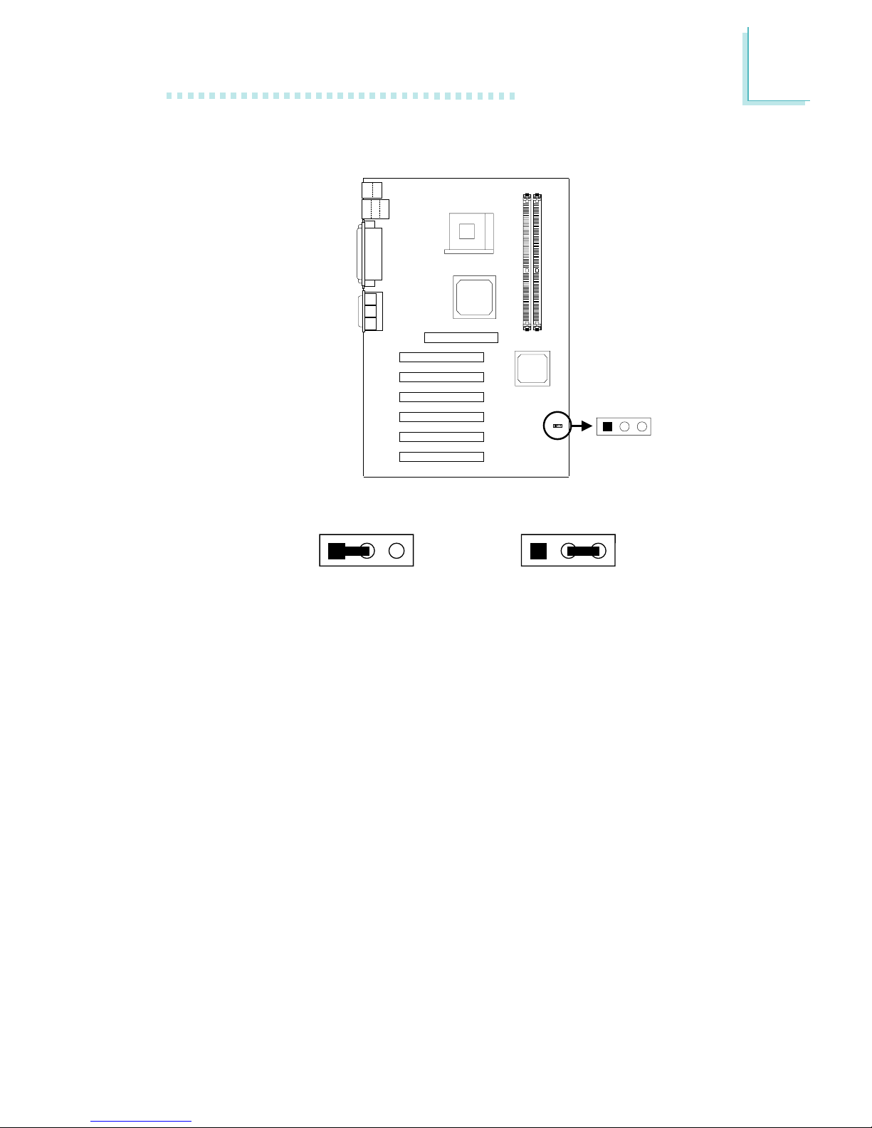
2.3 Jumper Settings for Clearing CMOS Data
Clear CMOS Data - Jumper JP2
If you encounter the following,
a) CMOS data becomes corrupted.
b) You forgot the supervisor or user password.
c) You are unable to boot-up the computer system because the
processor’s ratio/clock was incorrectly set in the BIOS.
you can reconfigure the system with the default values stored in the
ROM BIOS.
To load the default values stored in the ROM BIOS, please follow
the steps below.
1. Power-off the system.
2. Set JP2 pins 2 and 3 to On. Wait for a few seconds and set JP2
back to its default setting, pins 1 and 2 On.
2-3 On:
Clear CMOS Data
1-2 On: Normal
(default)
123 123
Clear CMOS
(JP2)
12
3

2
20
Hardware Installation
3. Now power-on the system.
If your reason for clearing the CMOS data is due to incorrect
setting of the processor’s ratio/clock in the BIOS, please proceed
to step 4.
4. After powering-on the system, press <Del> to enter the main
menu of the BIOS.
5. Select the CPU Frequency Control submenu and press <Enter>.
6. Set the “CPU Clock Ratio” or “Clock By Slight Adjust” field to its
default setting or an appropriate frequency ratio or bus clock.
Refer to the CPU Frequency Control section in chapter 3 for
more information.
7. Press <Esc> to return to the main menu of the BIOS setup
utility. Select “Save & Exit Setup” and press <Enter>.
8. Type <Y> and press <Enter>.
2
Hardware Installation
21
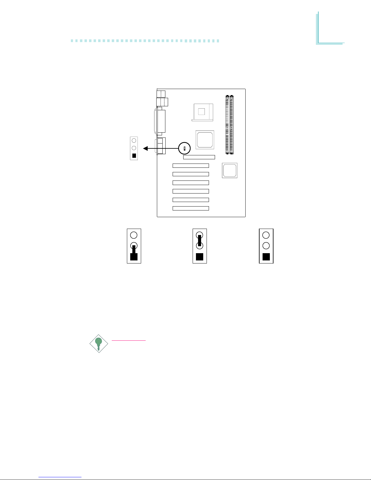
2.4 Jumper Settings for Selecting the CPU’s Front
Side Bus
CPU Front Side Bus Select - Jumper JP1
This jumper is used to select the front side bus of the CPU installed
on the system board.
Important:
Overclocking may result in the processor’s or system’s instability
and is not guaranteed to provide better system performance.
1-2 On: Auto
(default)
2-3 On: 100MHz
All Off: 133MHz
3
2
1
3
2
1
3
2
1
CPU FSB select
(JP1)
1
2
3
2
22
Hardware Installation
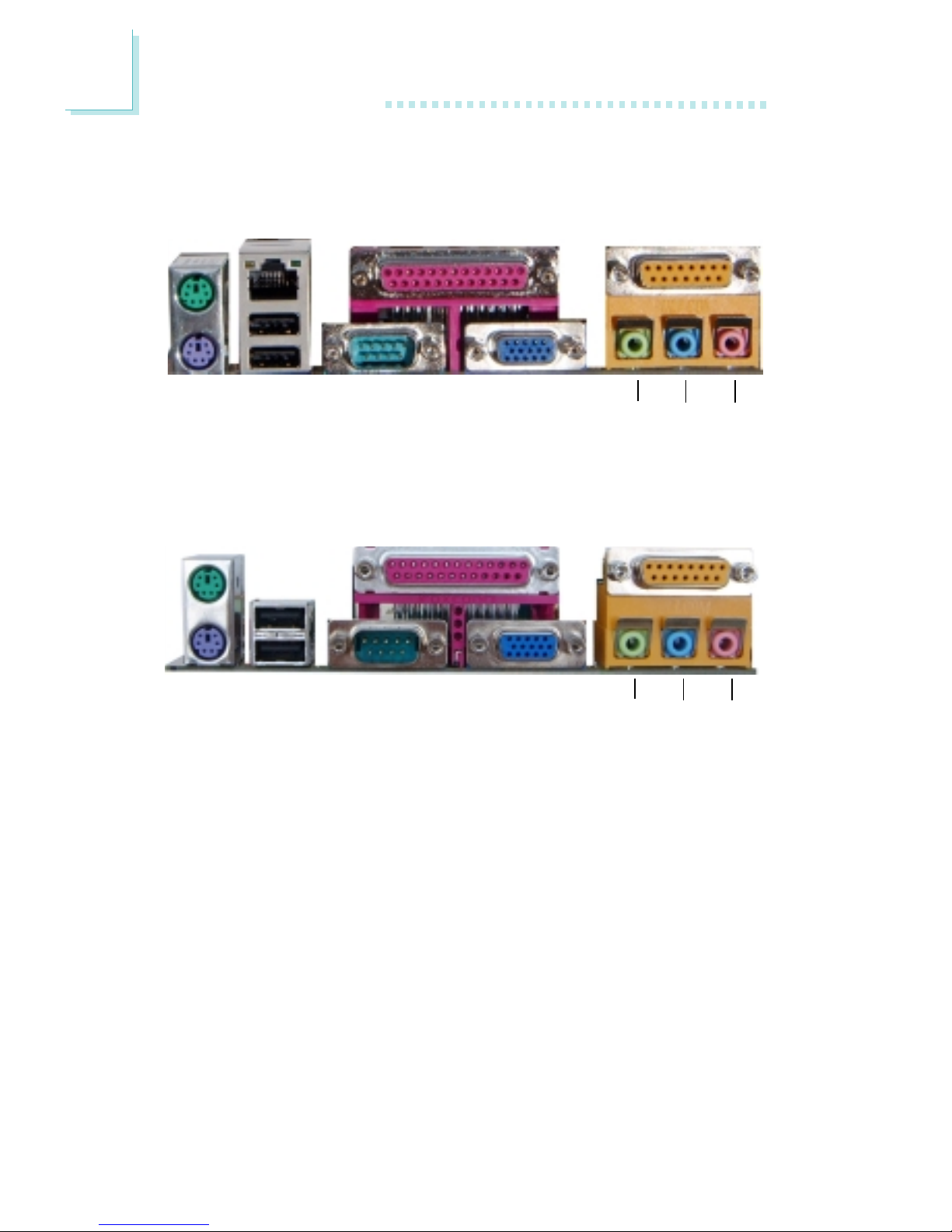
2.5 Rear Panel I/O Ports
PS/2
Mouse
RJ45
LAN
Parallel GAME/MIDI
PS/2
K/B
USB 1
COM 1 VGA
Line-
out
Line-inMic-
in
ATX Double Deck Ports on NB76-TL
PS/2
Mouse
Parallel GAME/MIDI
USB 2
USB 1 COM 1 VGA
Line-
out
Line-inMic-
in
PS/2
K/B
ATX Double Deck Ports on NB76-TC
2
Hardware Installation
23
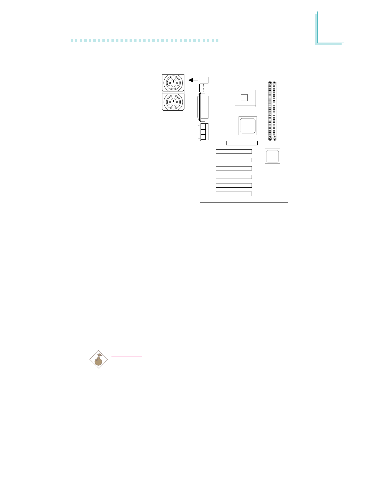
2.5.1 PS/2 Mouse and PS/2 Keyboard Ports
The system board is equipped with an onboard PS/2 mouse
(Green) and PS/2 keyboard (Purple) ports - both at location CN1
of the ATX double deck ports of the system board. The PS/2
mouse por t uses IRQ12. If a mouse is not connected to this por t,
the system will reserve IRQ12 for other expansion cards.
The Wake-On-Keyboard function allows you to use the keyboard to
power-on the system.
To use this function:
• “Keyboard Power On” (“Onboard Super IO Device” field) in the
Integrated Peripherals submenu of the BIOS must be set
accordingly. Refer to chapter 3 for more information.
Warning:
Make sure to turn off your computer prior to connecting or
disconnecting a mouse or keyboard. Failure to do so may
damage the system board.
PS/2 Mouse
PS/2 Keyboard
.
.
.
.
.
.
.
.
CN1

2
24
Hardware Installation
USB 2
USB 1
2.5.2 Universal Serial Bus Ports
Additional USB Ports (USB 3 to USB 6)
Pin
1
3
5
7
9
Function
5V_Dul
Data-
Data+
Ground
Key
Function
5V_Dul
Data-
Data+
Ground
OC-
Pin
2
4
6
8
10
CN7
2
1
9
10
2
1
9
10
USB 3/4
(JUSB1)
USB 5/6
(JUSB2)
2
1
10
9
2
1
10
9

2
Hardware Installation
25
The system board supports 6 USB 2.0/1.1 ports. USB 1.1 supports
12Mb/second bandwidth while USB 2.0 supports 480Mb/second
bandwidth providing a marked improvement in device transfer
speeds between your computer and a wide range of simultaneously
accessible external Plug and Play peripherals. You must have the
proper drivers installed in your operating system to use the USB
ports. Refer to your operating system’s manual or documentation.
Two onboard USB 2.0/1.1 por ts (CN7 - Black) are located at the
ATX double deck por ts of the board.
The system board is also equipped with JUSB1 and JUSB2 for
connecting 4 external USB 2.0/1.1 ports. The USB 2.0/1.1 ports,
which are mounted on a card-edge bracket, will be provided as an
option. If you wish to use the optional USB 2.0/1.1 ports, install the
card-edge bracket to the system chassis then insert the connector
that is attached to the USB 2.0/1.1 port cables to JUSB1 or JUSB2.
The USB ports’ cable connector can be inserted only if pin 1 of the
connector is aligned with pin 1 of JUSB1 or JUSB2. Now connect the
interface cable connector of your USB 2.0/1.1 device to the USB
2.0/1.1 port that is on the bracket.
You can enable or disable the USB por ts in the Integrated Peripherals submenu (“USB Controller” field) of the BIOS.
The Wake-On-USB Keyboard function allows you to use a USB
keyboard to wake up a system that is in the S3 (STR - Suspend To
RAM) state.
To use this function:
• “USB KB Wake-Up From S3” in the Power Management Setup
submenu of the BIOS must be set to Enabled.
2
26
Hardware Installation
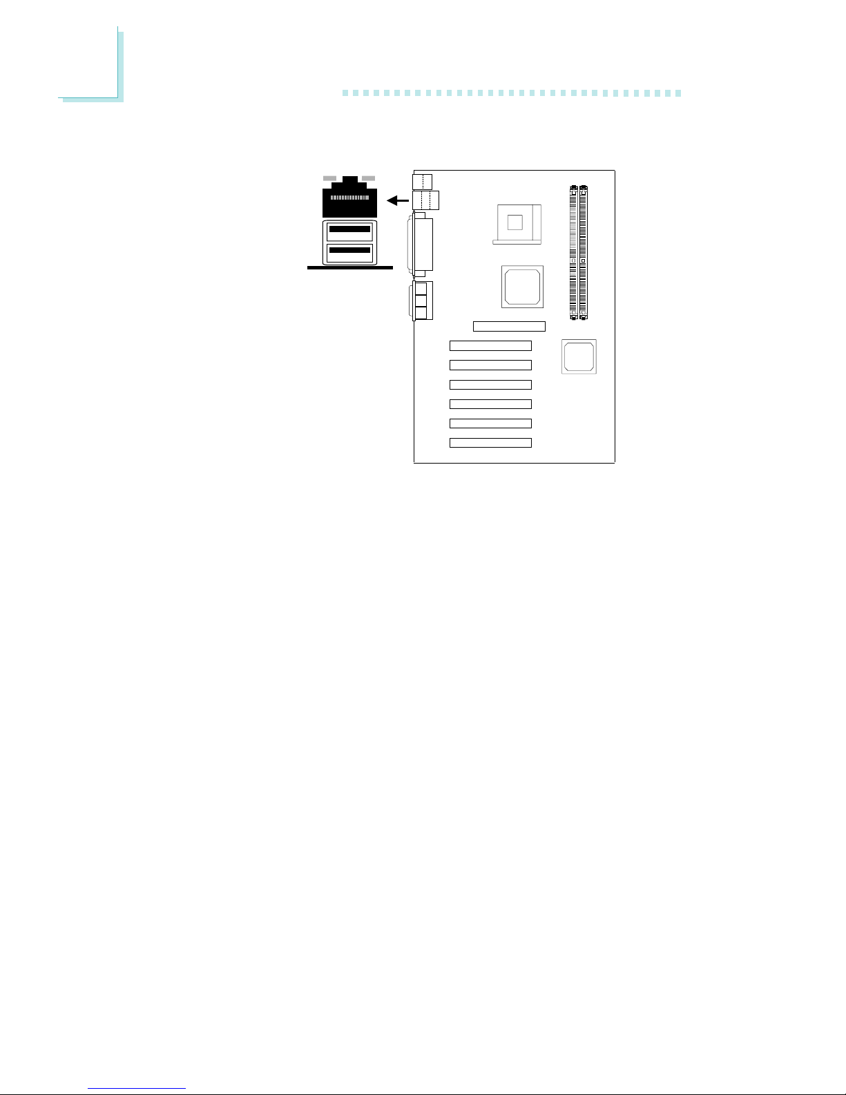
2.5.3 RJ45 Fast-Ethernet Port (NB76-TL only)
The NB76-TL system board is equipped with an onboard RJ45 fastethernet LAN port at location CN7 of the ATX double deck ports.
It allows the system board to connect to a local area network by
means of a network hub. The Realtek RTL8100 chip that controls
this port can be enabled or disabled in the Integrated Peripherals
submenu (“Intel OnChip PCI Device” field) of the BIOS. Refer to the
Integrated Peripherals section in chapter 3 for more information.
RJ45 LAN
CN7
2
Hardware Installation
27
CN6
COM 2
(J6)
2
1
9
2
1
9
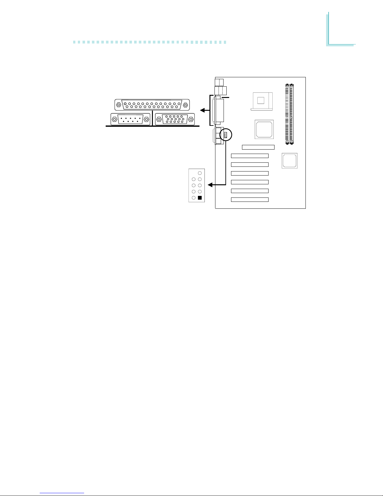
2.5.4 Serial Ports
The built-in serial ports are RS-232C asynchronous communication
ports with 16C550A-compatible UARTs that can be used with
modems, serial printers, remote display terminals, and other serial
devices. You can select the serial ports’ I/O address in the Integrated
Peripherals submenu (“Onboard Super IO Device” field) of the
BIOS.
Connecting the Serial Ports
The system board is equipped with an onboard serial port (CN6 Teal/Turquoise) for COM 1 primary serial port located at the ATX
double deck ports of the board. It is also equipped with a 9-pin
connector at location J6 for COM 2 secondary serial port.
One card-edge bracket, mounted with a serial port cable, is
provided with the system board. If you want to use the secondary
serial por t, connect the serial port cable to connector J6. Make sure
the colored stripe on the ribbon cable is aligned with pin 1 of
connector J6. Mount the card-edge bracket to the system chassis.
COM 1
Serial Port
2
28
Hardware Installation
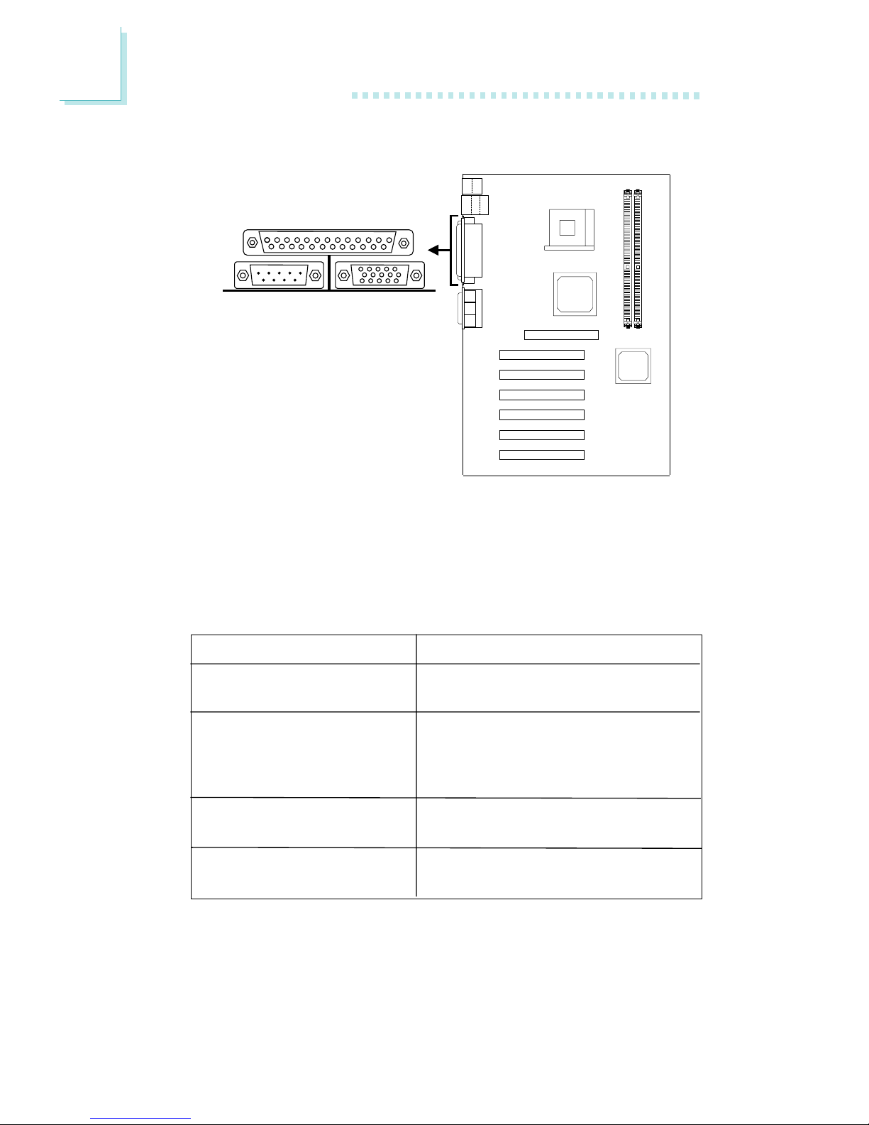
Parallel Port
2.5.5 Parallel Port
The system board has a standard parallel port (CN8 - Burgundy)
located at the ATX double deck ports of the board for interfacing
your PC to a parallel printer. It supports SPP, ECP, EPP and PntMode
modes. You can select the port’s mode in the Integrated Peripherals
submenu (“Onboard Super IO Device” field) of the BIOS.
Setting
SPP
(Standard Parallel Port)
ECP
(Extended Capabilities Port)
EPP
(Enhanced Parallel Port)
PntMode
Function
Allows normal speed operation but
in one direction only.
Allows parallel port to operate in
bidirectional mode and at a speed
faster than the SPP’s data transfer
rate.
Allows bidirectional parallel port operation at maximum speed.
Allows parallel port to operate in
bipolar mode.
CN8
2
Hardware Installation
29
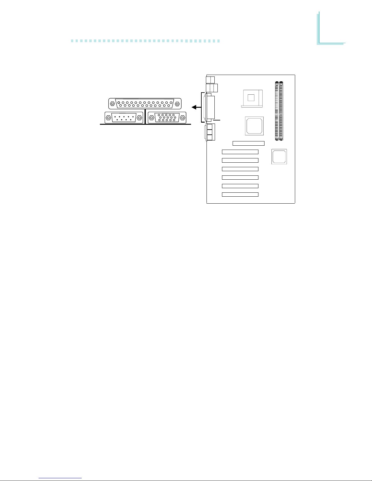
CN2
2.5.6 VGA Port
The system board can only be used with an analog video monitor.
Connect the monitor’s 15-pin D-shell cable connector to the VGA
port (CN2 - Blue) located at the ATX double deck ports of the
board. If your monitor suppor ts analog video but does not have a
15-pin D-shell connector, see your monitor dealer for the adapter or
optional cable. After you plug the monitor cable into the VGA port,
gently tighten the cable screws to hold the connector in place. Some
monitors have a switch that chooses between analog and TTL (or
digital) operation. If your monitor has such a switch, set it for analog.
You can enable or disable the VGA por t in the Advanced Chipset
Features submenu (“On-Chip Video” field) of the BIOS.
VGA Port
2
30
Hardware Installation
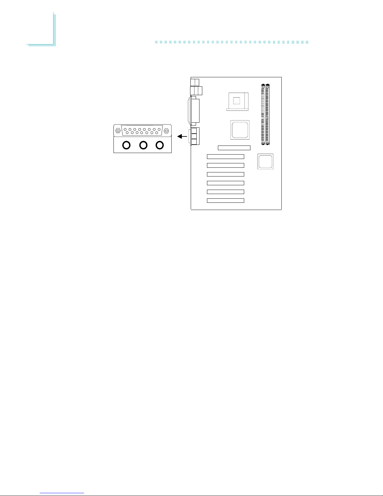
2.5.7 Game/MIDI Port
The Game/MIDI por t is identical to that of a standard PC game
adapter or game I/O port. Connect an analog joystick to the 15-pin
D-sub connector (CN9 - Gold) located at the ATX double deck
ports of the system board. This por t works well with any application
that is compatible with the standard PC joystick. You can configure
the game port in the Integrated Peripherals submenu (“Onboard
Super IO Device” field) of the BIOS.
Game Port
CN9
 Loading...