

DFI NB76-BC, NB76-BL User Manual

NB76-BC
NB76-BL
Rev. A+
System Board User’s Manual
Carte Mère Manuel Pour Utilisateur
System-Platine Benutzerhandbuch
Manual del Usuario de Placas Base
935-NB7601-300
62300231

Copyright
This publication contains information that is protected by copyright.
No par t of it may be reproduced in any form or by any means or
used to make any transformation/adaptation without the prior
written permission from the copyright holders.
This publication is provided for informational purposes only. The
manufacturer makes no representations or warranties with respect to
the contents or use of this manual and specifically disclaims any
express or implied warranties of merchantability or fitness for any
par ticular purpose . The user will assume the entire risk of the use or
the results of the use of this document. Further, the manufacturer
reserves the r ight to revise this publication and make changes to its
contents at any time, without obligation to notify any person or
entity of such revisions or changes.
© 2002. All Rights Reserved.
Trademarks
Windows® 98 SE, Windows® ME, Windows® 2000, Windows NT
®
4.0 and Windows® XP are registered trademarks of Microsoft
Corporation. Intel® and Pentium® 4 are registered trademarks of
Intel Corporation. Award is a registered trademark of Award
Software, Inc. Other trademarks and registered trademarks of
products appearing in this manual are the properties of their
respective holders.
Caution
To avoid damage to the system:
• Use the correct AC input voltage r ange
..
..
.
To reduce the risk of electr ic shock:
• Unplug the power cord before removing the system chassis
cover for installation or servicing. After installation or ser vicing,
cover the system chassis before plugging the power cord.

Battery:
• Danger of explosion if batter y incor rectly replaced.
• Replace only with the same or equivalent type recommend
by
the manufacturer.
• Dispose of used batteries according to the battery
manufacturer’s
instructions.
Joystick or MIDI por t:
• Do not use any joystick or MIDI device that requires more than
10A current at 5V DC. There is a risk of fire for devices that
exceed this limit.
FCC and DOC Statement on Class B
This equipment has been tested and found to comply with the limits
for a Class B digital device, pursuant to Par t 15 of the FCC rules.
These limits are designed to provide reasonable protection against
harmful interference when the equipment is operated in a residential
installation. This equipment generates, uses and can radiate radio
frequency energy and, if not installed and used in accordance with
the instruction manual, may cause harmful interference to radio
communications. However, there is no guarantee that interference
will not occur in a par ticular installation. If this equipment does cause
harmful interference to radio or television reception, which can be
determined by turning the equipment off and on, the user is
encouraged to tr y to correct the interference by one or more of the
following measures:
• Reorient or relocate the receiving antenna.
• Increase the separation between the equipment and the receiver.
• Connect the equipment into an outlet on a circuit different from
that to which the receiver is connected.
• Consult the dealer or an experienced radio TV technician for
help.
Notice:
1. The changes or modifications not expressly approved by the
par ty responsible for compliance could void the user's authority
to operate the equipment.
2. Shielded interface cables must be used in order to comply with
the emission limits.

4
Quick Setup Guide
1
Quick Setup
Guide
Table of Contents
Chapter 1
Quick Setup Guide.............................................
Chapter 2
English......................................................................
Chapter 3
Français (French).................................................
Chapter 4
Deutsch (German)................................................
Chapter 5
Español (Spanish)..................................................
5
35
50
67
84
NB76-BC/BL Intel 845G
AGP slot
“BL” supports onboard LAN and Smar t I/O

5
1
Quick Setup Guide
Quick Setup
Guide
Chapter 1 - Quick Setup Guide
Table of Contents
1.1 System Board Layout..................................................................................................
1.2 Jumpers.....................................................................................................................................
1.3 Por ts and Connector s................................................................................................
1.4 Award BIOS Setup Utility.......................................................................................
6
9
12
27
Note:
The user’s manual in the provided CD contains detailed information
about the system board. If, in some cases, some information doesn’t
match those shown in this manual, this manual should always be
regarded as the most updated version.
6
Quick Setup Guide
1
Quick Setup
Guide
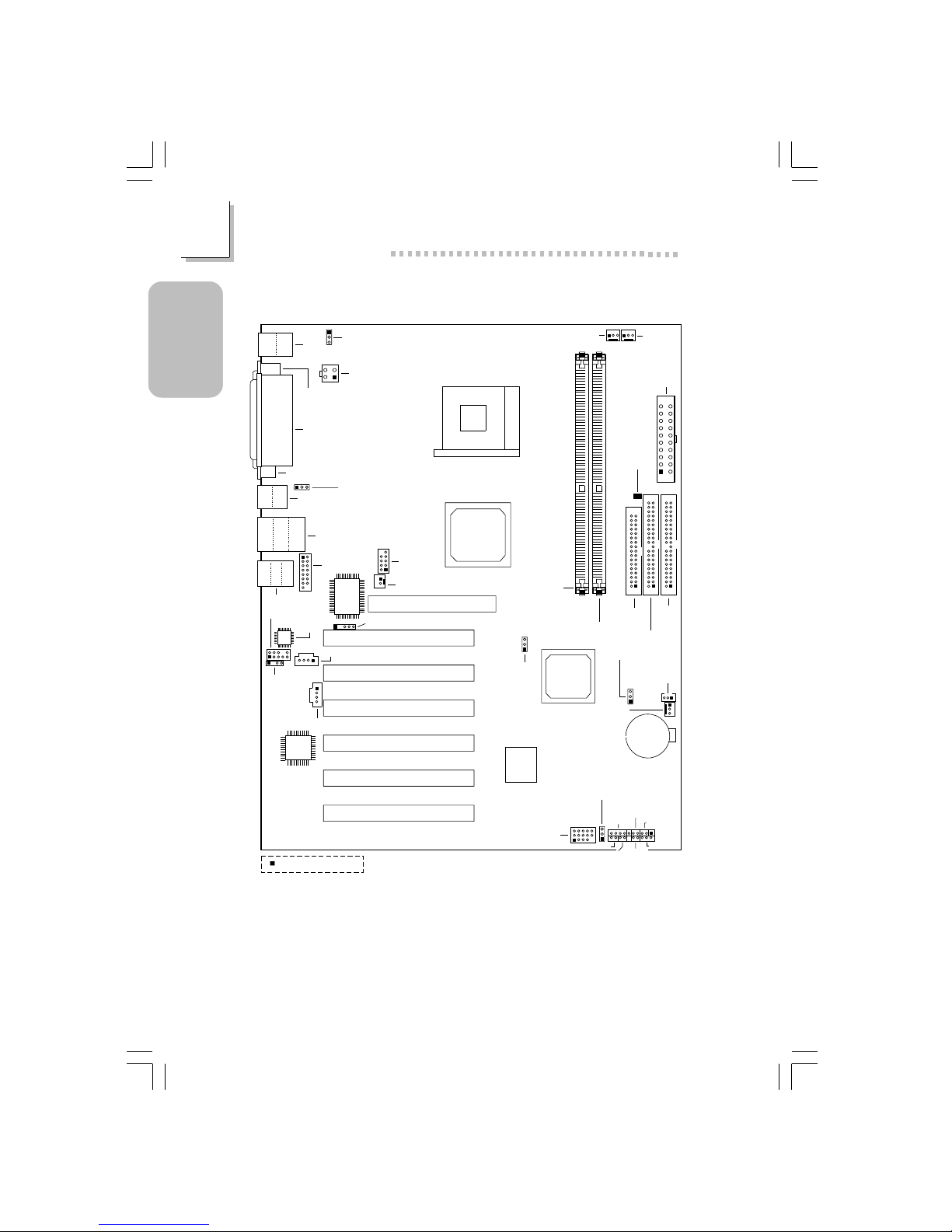
1.1 System Board Layout
KB
Mouse
CN4
COM 1
(CN2)
Parallel (CN6)
VGA (CN1)
Wake-On-KB/Mouse
(JP1)
+12V power
(ATXP1)
4
321
CN3
USB 1
USB 2
LAN
USB 3
USB 4
CN7
Line-out
Line-in
Mic-in
CN5
Game/MIDI
(J6)
1
2
15
1
2
9
I/O
chip
IrDA (J11)
AC’97
Front audio (J2)
Realtek
RTL8100
Socket 478
DDR SDRAM
DIMM 1
DDR SDRAM
DIMM 2
Intel
845G
GMCH
Intel
ICH4
CPU FSB
select (JP4)
Clear CMOS (JP7)
Wake-On-
LAN (J23)
Chassis
fan (J25)
Battery
CPU fan
(J18)
Second
fan (J19)
ATX main
power (PL1)
DIMM
Standby
Power LED
FDD (J21)
IDE 2 (J22)
IDE 1
(J24)
Firmware
Hub
J20
PWR-LED
G-SW
RESET
SPEAKER
G-LED
HD-LED
Square denotes pin 1
ATX-SW
AGP Slot
PCI Slot 1
PCI Slot 2
PCI Slot 3
PCI Slot 4
PCI Slot 5
PCI Slot 6
CN3
Wake-On-USB KB
for USB 1/2/3/4 (JP9)
COM 2
(J13)
Wake-On-Ring (J12)
USB 5 & 6
(J14)
Wake-On-USB KB for
USB 5/6 (JP8)
CD-in (J8)
TAD (J7)
S/PDIF-out
(J1)
NB76-BL
(Supports onboard LAN)
7
1
Quick Setup Guide
Quick Setup
Guide
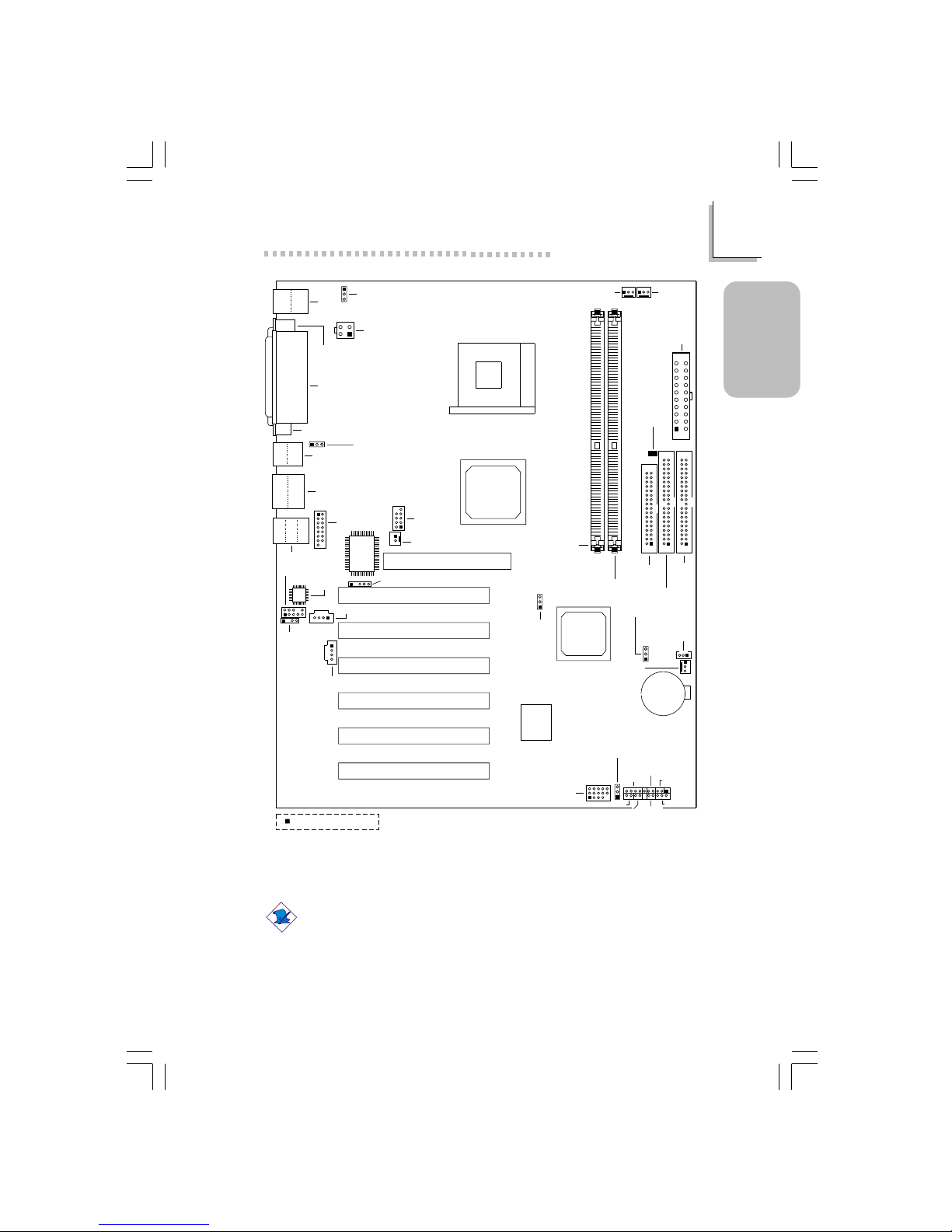
Note:
The illustrations on the following pages are based on the system
board that supports onboard LAN.
KB
Mouse
CN4
COM 1
(CN2)
Parallel (CN6)
VGA (CN1)
Wake-On-KB/Mouse
(JP1)
+12V power
(ATXP1)
4
321
CN3
USB 1
USB 2
USB 3
USB 4
CN7
Line-out
Line-in
Mic-in
CN5
Game/MIDI
(J6)
1
2
15
1
2
9
I/O
chip
IrDA (J11)
AC’97
Front audio (J2)
Socket 478
DDR SDRAM
DIMM 1
DDR SDRAM
DIMM 2
Intel
845G
GMCH
Intel
ICH4
CPU FSB
select (JP4)
Clear CMOS (JP7)
Wake-On-
LAN (J23)
Chassis
fan (J25)
Battery
CPU fan
(J18)
Second
fan (J19)
ATX main
power (PL1)
DIMM
Standby
Power LED
FDD (J21)
IDE 2 (J22)
IDE 1
(J24)
Firmware
Hub
J20
PWR-LED
G-SW
RESET
SPEAKER
G-LED
HD-LED
Square denotes pin 1
ATX-SW
AGP Slot
PCI Slot 1
PCI Slot 2
PCI Slot 3
PCI Slot 4
PCI Slot 5
PCI Slot 6
CN3
Wake-On-USB KB
for USB 1/2/3/4 (JP9)
COM 2
(J13)
Wake-On-Ring (J12)
USB5&6
(J14)
Wake-On-USB KB for
USB 5/6 (JP8)
CD-in (J8)
TAD (J7)
S/PDIF-out
(J1)
NB76-BC

8
Quick Setup Guide
1
Quick Setup
Guide
Warning:
Electrostatic discharge (ESD) can damage your system board,
processor, disk drives, add-in boards, and other components. Perform
the upgrade instruction procedures described at an ESD workstation
only. If such a station is not available, you can provide some ESD
protection by wearing an antistatic wrist strap and attaching it to a
metal part of the system chassis. If a wrist strap is unavailable,
establish and maintain contact with the system chassis throughout
any procedures requiring ESD protection.
9
1
Quick Setup Guide
Quick Setup
Guide
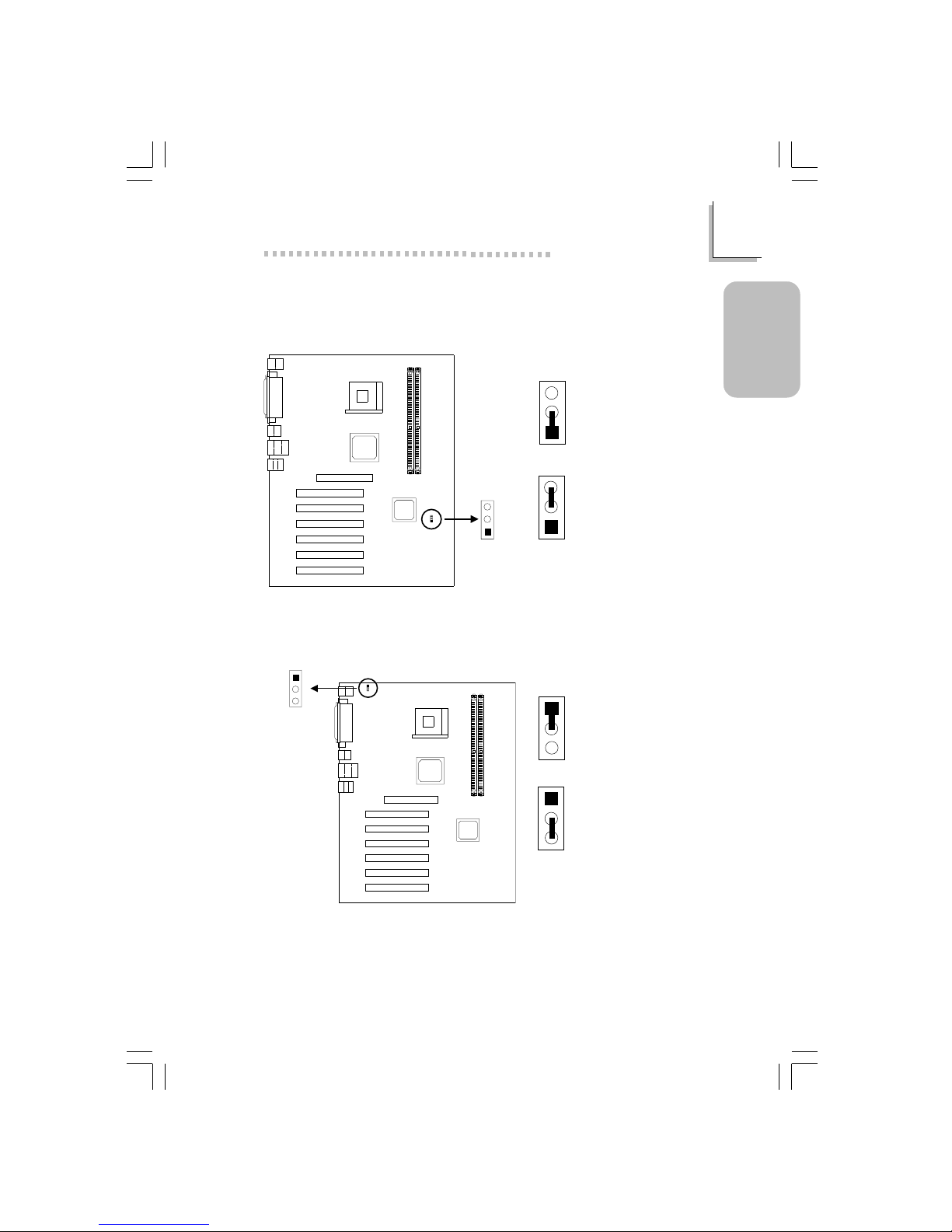
1.2 Jumpers
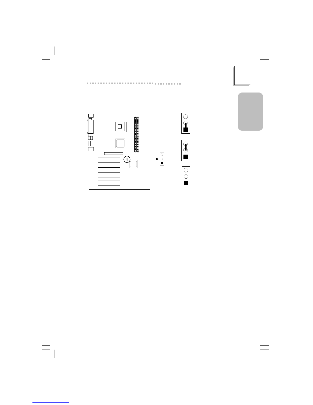
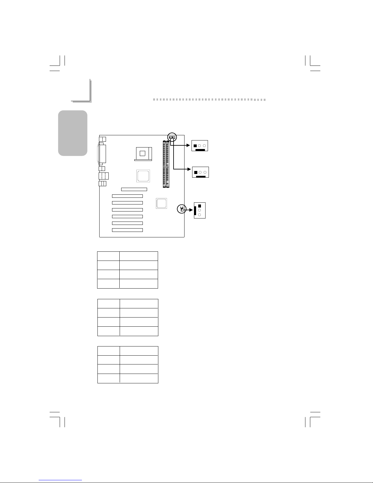
1.2.1 Clear CMOS Data - JP7
3
2
1
3
2
1
1-2 On:
Normal (default)
2-3 On:
Clear CMOS Data
Clear CMOS
(JP7)
1
2
3
1.2.2 Jumper Settings for Wake-On-Keyboard/Wake-OnMouse - JP1
Wake-On-
KB/Mouse (JP1)
1
2
3
1
2
3
1-2 On: Disable
(default)
1
2
3
2-3 On: Enable
If JP1 was enabled with a password set in the “KB Power On Password” field,
and now you wish to disable the keyboard password function, make sure to
set the “Keyboard/Mouse Power On” field to Disabled prior to setting JP1 to
disabled. You will not be able to boot up the system if you fail to do so.
10
Quick Setup Guide
1
Quick Setup
Guide
The power button will not function once a keyboard password has been set
in the “KB Power On Password” (“Onboard Super IO Device” field) of the
Integrated Peripherals submenu. You must type the correct password to
power-on the system.
The 5VSB power source of your power supply must support ≥720mA.
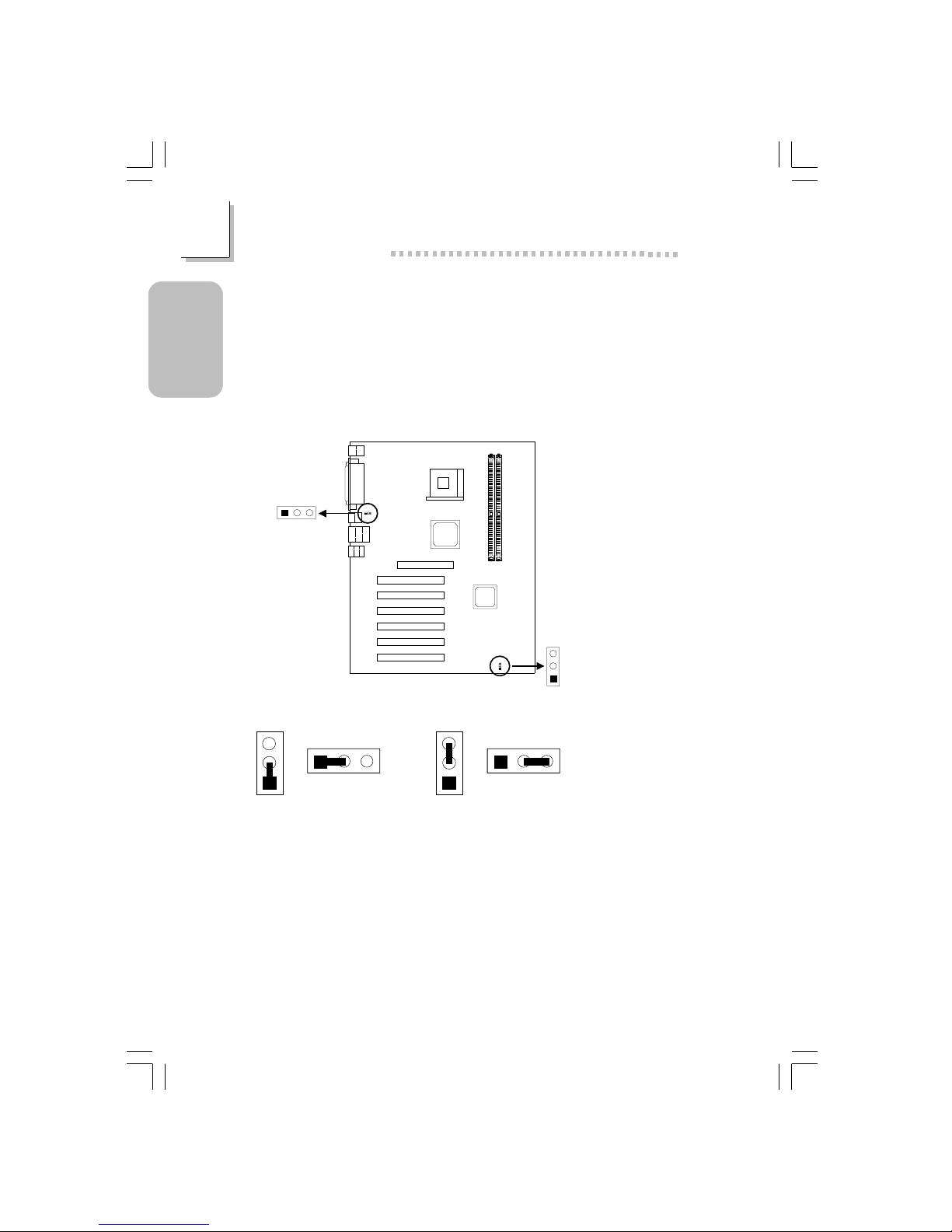
1.2.3 Jumper Settings for Wake-On-USB Keyboard
Wake-On-USB (KB)
1/2/3/4 (JP9)
Wake-On-USB
(KB) 5/6 (JP8)
1
2
3
12
3
2-3 On: Enable
(default)
1-2 On: Disable
123
JP8
JP9
3
2
1
123
JP8
JP9
3
2
1
If you are using the Wake-On-USB Keyboard function for 2 USB ports, the
5VSB power source of your power supply must support ≥1.5A.
If you are using the Wake-On-USB Keyboard function for 4 or more USB
ports, the 5VSB power source of your power supply must support ≥2A.
11
1
Quick Setup Guide
Quick Setup
Guide
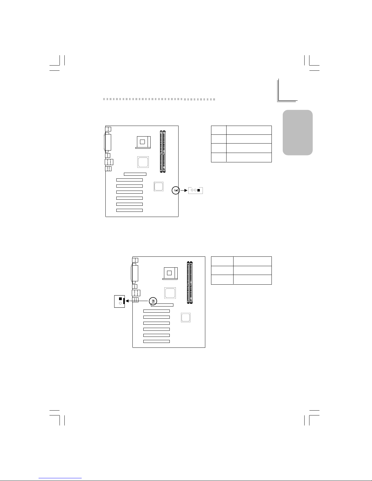
1.2.4 Jumper Settings for Selecting the CPU’s Front Side
Bus
CPU FSB select
(JP4)
1
2
3
3
2
1
3
2
1
3
2
1
1-2 On: Auto
(default)
2-3 On: 100MHz
All Off: 133MHz

12
Quick Setup Guide
1
Quick Setup
Guide
1.3 Ports and Connectors
PS/2
Mouse
PS/2
K/B
RJ45
LAN
USB 4/3COM 1 VGA
Parallel
Line-out
Line-in
Mic-in
USB 1
ATX Double Deck Ports on NB76-BL
PS/2
Mouse
PS/2
K/B
USB 3COM 1 VGA
Parallel
Line-out
Line-in
Mic-in
USB 1
ATX Double Deck Ports on NB76-BC
USB 4
USB 2
USB 2

13
1
Quick Setup Guide
Quick Setup
Guide
1.3.1 PS/2 Mouse and PS/2 Keyboard Ports
Make sure to turn off your
computer prior to connecting or
disconnecting a mouse or keyboard.
Failure to do so may damage the
system board.
PS/2 Mouse
PS/2 Keyboard
CN4
1.3.2 Serial Ports
CN2
1
2
9
COM 2
(J13)
2
1
9
COM 1
Serial Port
14
Quick Setup Guide
1
Quick Setup
Guide
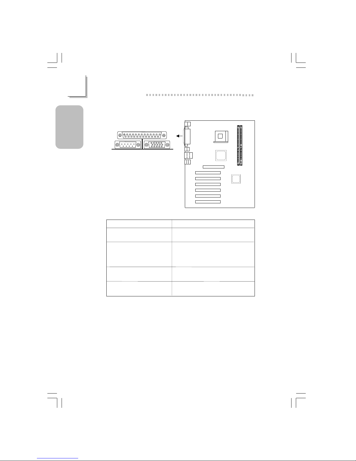
1.3.3 Parallel Port
CN6
Parallel Port
Setting
SPP
(Standard Parallel Port)
ECP
(Extended Capabilities Port)
EPP
(Enhanced Parallel Port)
PntMode
Function
Allows normal speed operation but
in one direction only .
Allows parallel port to operate in
bidirectional mode and at a speed
faster than the SPP’s data transfer
rate.
Allows bidirectional parallel port operation at maximum speed.
Allows parallel port to operate in
bipolar mode.
15
1
Quick Setup Guide
Quick Setup
Guide
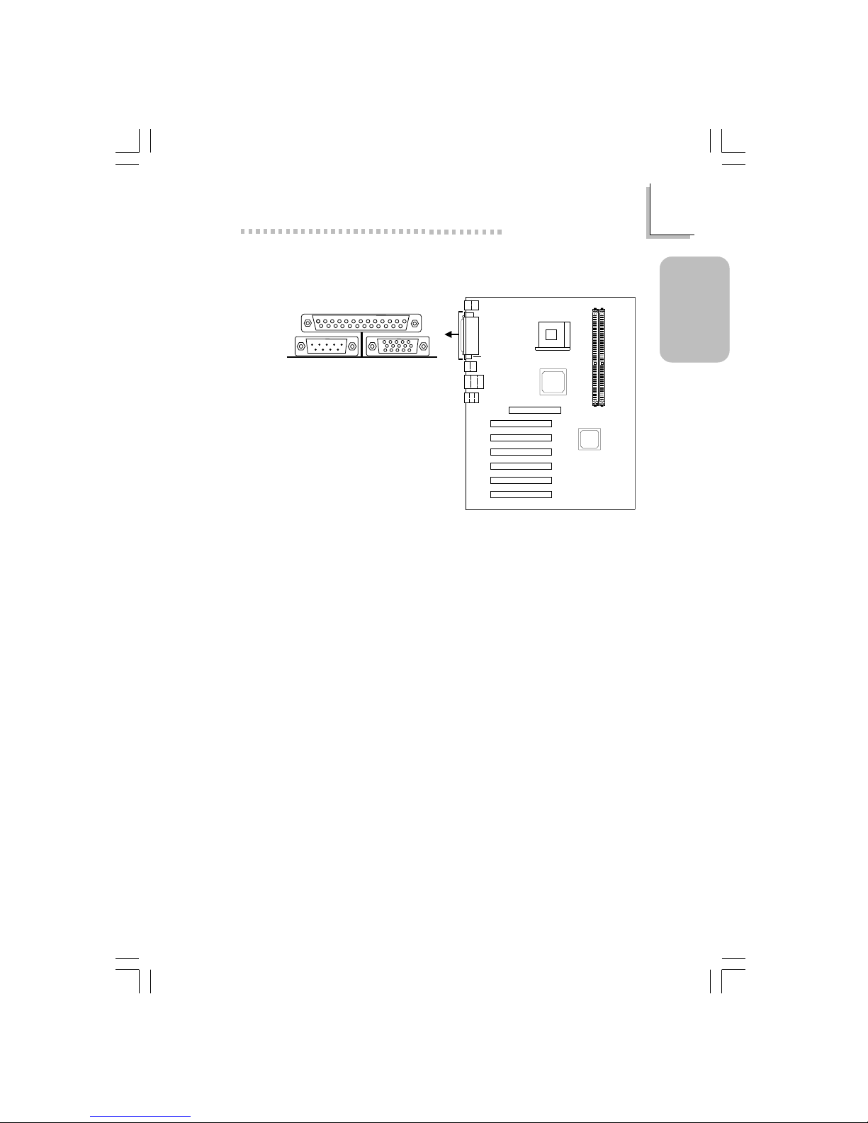
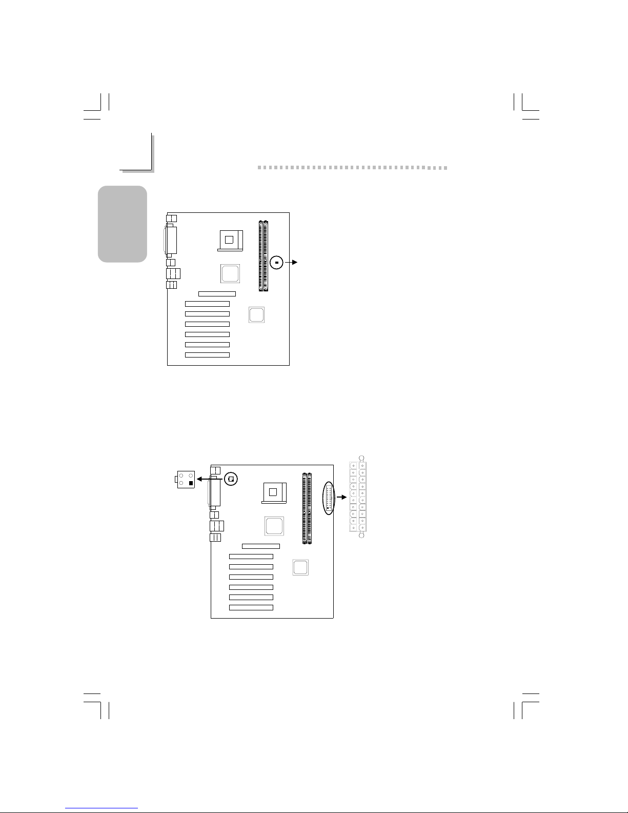
1.3.4 VGA Port
CN1
VGA Por t
16
Quick Setup Guide
1
Quick Setup
Guide
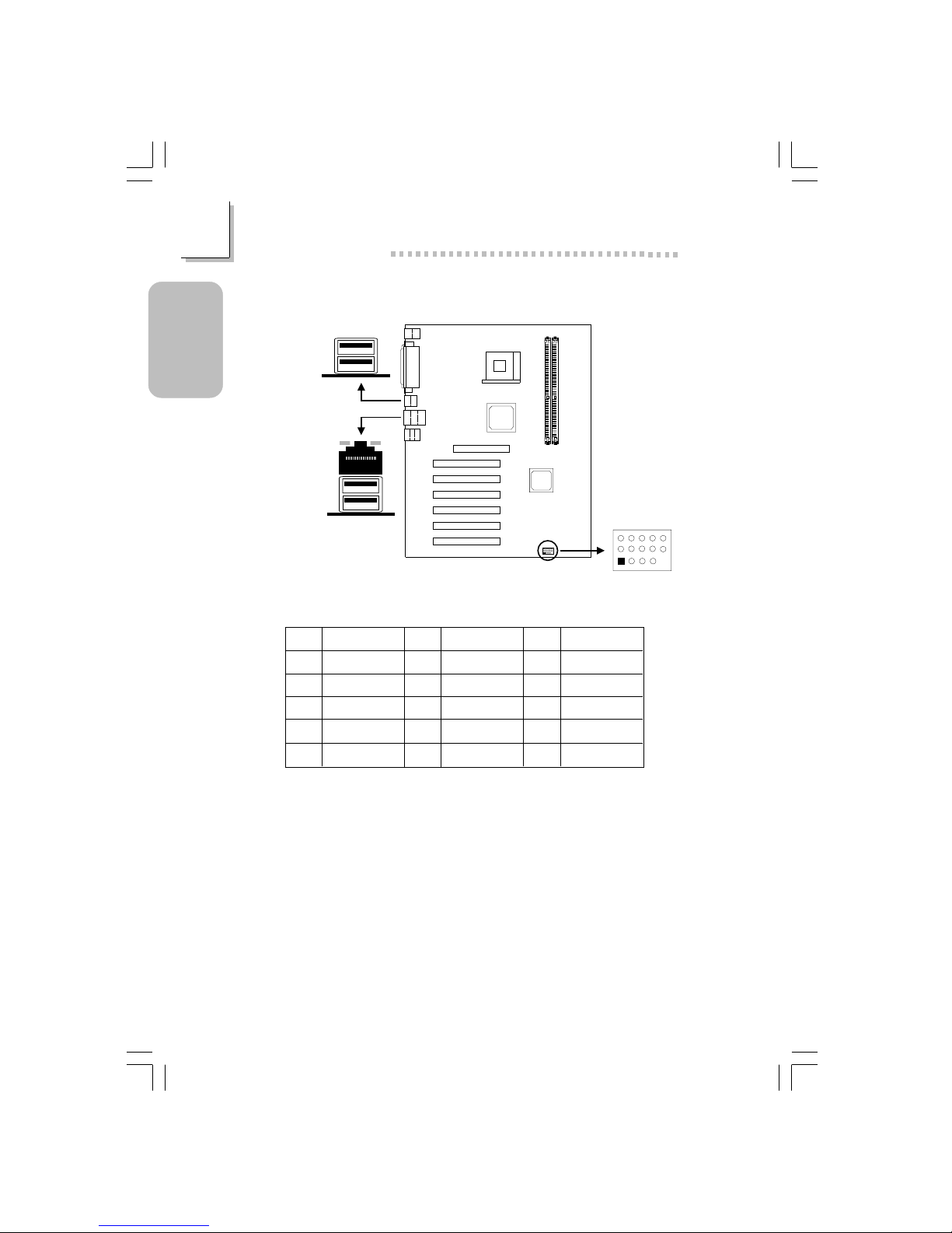
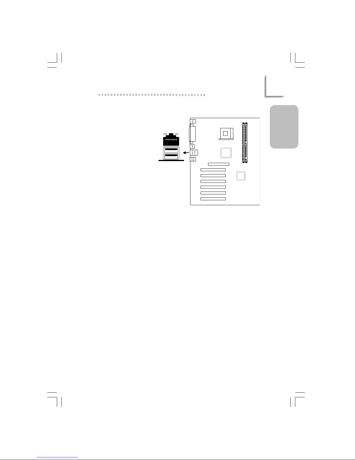
1.3.5 Universal Serial Bus Ports
CN3
CN7
5
15
11
1
USB5&6(J14)
USB 1
USB 4
USB 3
USB 2
Pin
1
2
3
4
5
Function
VCC
UP5-
UP5+
Ground
Key
Pin
6
7
8
9
10
Function
VCC
UP6-
UP6+
Ground
Ground
Pin
11
12
13
14
15
Function
Ground
Ground
UP5+
UP5VCC
Additional USB Ports (USB 5 and USB 6)
17
1
Quick Setup Guide
Quick Setup
Guide
1.3.6 RJ45 Fast-Ethernet Port (NB76-BL only)
CN7
RJ45 LAN
18
Quick Setup Guide
1
Quick Setup
Guide
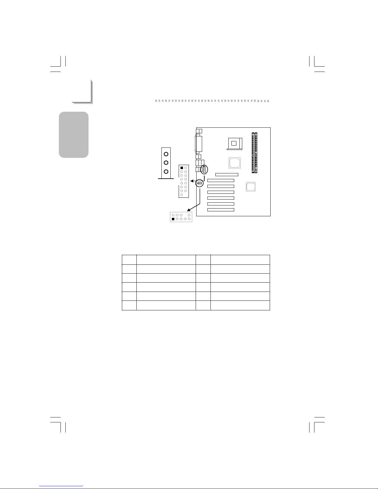
1.3.7 Audio Jacks and Game/MIDI por ts
Front Audio (J2)
Pin
1
3
5
7
9
Function
Mic+
Vbias
AuD_R_Out
N. C .
AuD_L_Out
Function
Ground
AuD_Vcc (Avcc)
N. C.
Key
N. C.
Pin
2
4
6
8
10
Game/MIDI
(J6)
1
2
15
2
15
1
Front audio
(J2)
2
1
10
9
Line-out
Line-in
Mic-in
19
1
Quick Setup Guide
Quick Setup
Guide
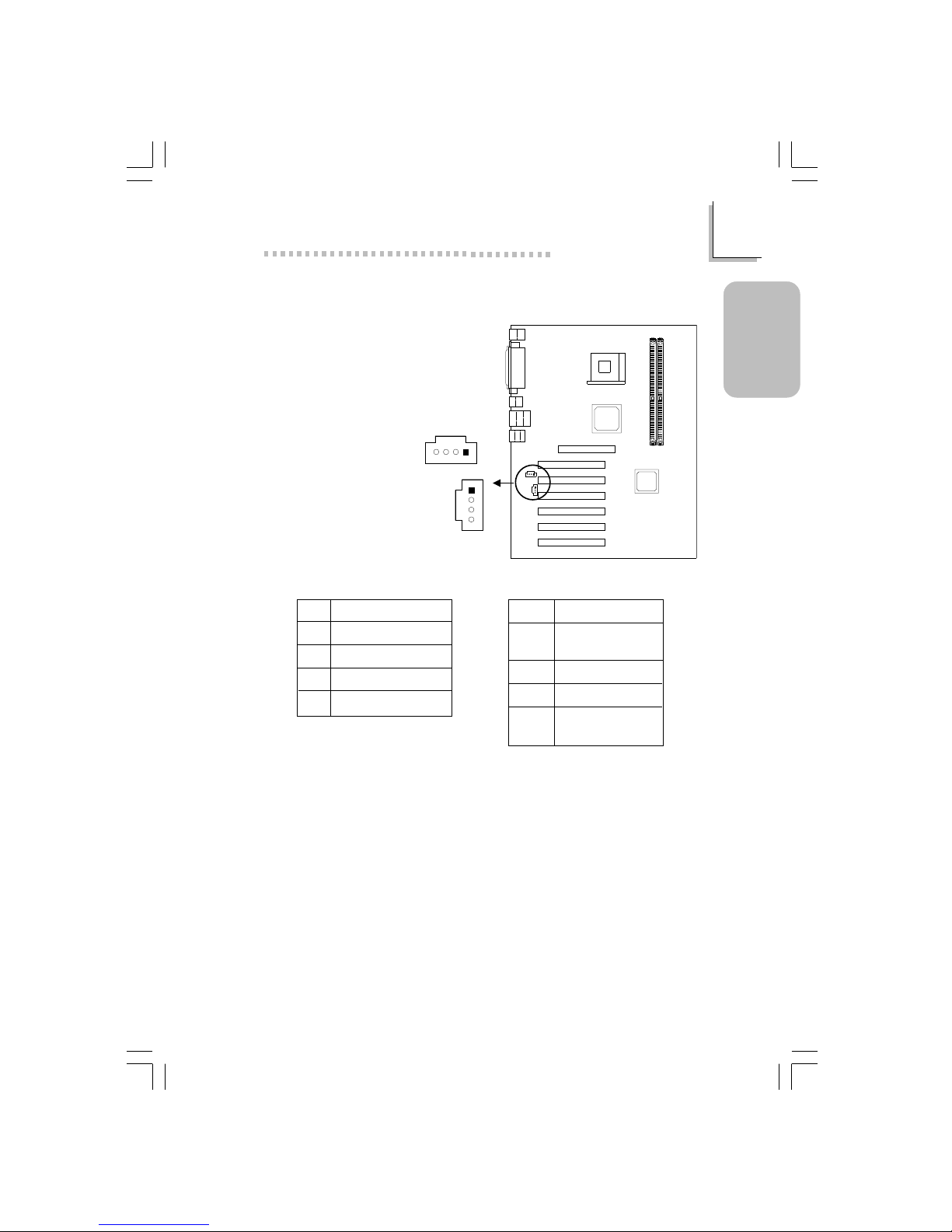
1.3.8 Internal Audio Connectors
4
3
2
1
CD-in (J8)
TAD (J7)
4
3
2
1
Pin
1
2
3
4
Function
Left audio channel
Ground
Ground
Right audio channel
Pin
1
2
3
4
Function
Modem-out
(from modem)
Ground
Ground
Modem-in
(to modem)
CD-in TAD
20
Quick Setup Guide
1
Quick Setup
Guide
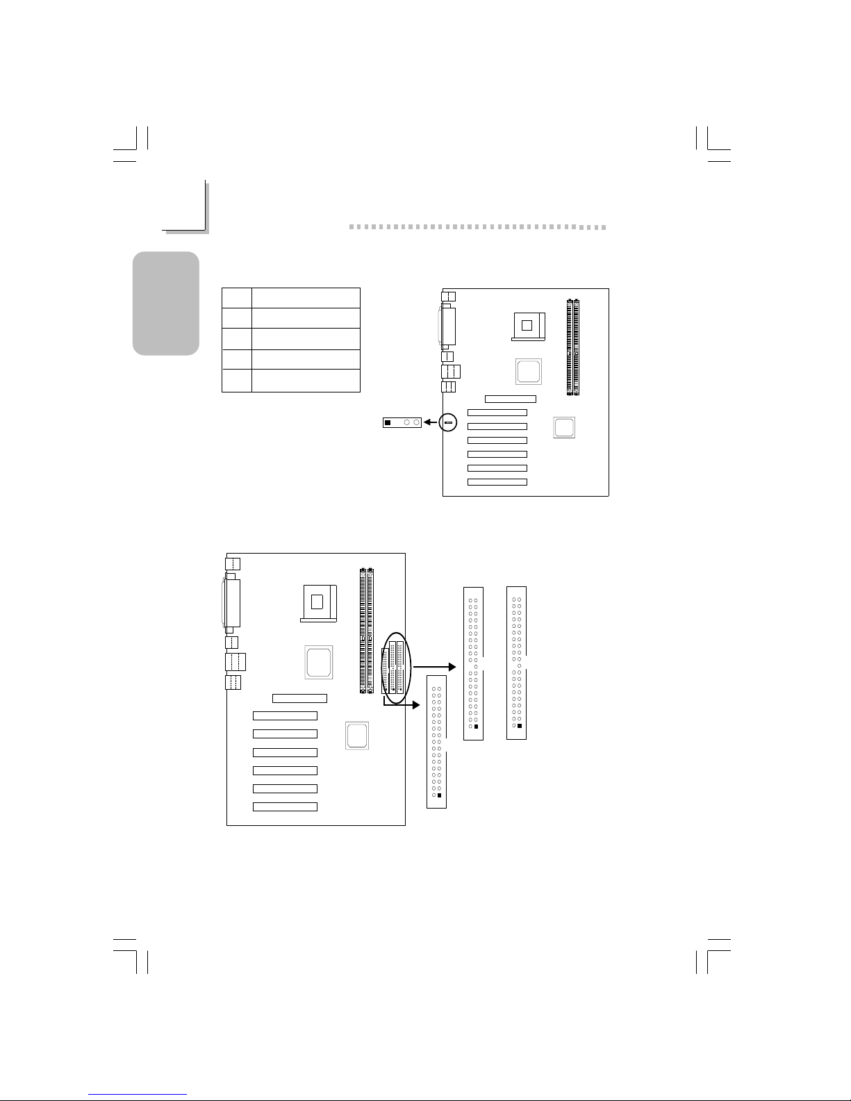
1.3.9 S/PDIF-out Connector
S/PDIF-out
(J1)
1234
Pin
1
2
3
4
Function
AVDD5
N. C .
SPDIF-out
Ground
1.3.10 Floppy & IDE Disk Drive Connector
IDE 2 (J22)
IDE 1 (J24)
1
2
40
39
1
2
40
39
FDD (J21)
1
2
33
34
If you encountered problems while using an ATAPI CD-ROM drive that is set
in Master mode, please set the CD-ROM drive to Slave mode. Some ATAPI
CD-ROMs may not be recognized and cannot be used if incorrectly set in
Master mode.

21
1
Quick Setup Guide
Quick Setup
Guide
1.3.11 IrDA Connector
IrDA (J11)
1234
5
Pin
1
2
3
4
5
Function
VCC
N. C.
IRRX
Ground
IRTX
The sequence of the pin functions on some IrDA cable may be reversed
from the pin function defined on the system board. Make sure to connect
the cable to the IrDA connector according to their pin functions.
22
Quick Setup Guide
1
Quick Setup
Guide
CPU fan
(J18)
3
2
1
Chassis fan
(J25)
3
2
1
Second fan
(J19)
3
2
1
Pin
1
2
3
Function
Ground
Power
N. C.
Pin
1
2
3
Function
Ground
Power
N. C.
Pin
1
2
3
Function
Ground
Power
N. C.
1.3.12 CPU Fan, Chassis Fan and Second Chassis fan
Connector
23
1
Quick Setup Guide
Quick Setup
Guide
1.3.13 Wake-On-LAN Connector
Wake-On-LAN
(J23)
3
2
1
Pin
1
2
3
Function
WOL
Ground
+5VSB
The 5VSB power source of your power supply must support ≥720mA.
1.3.14 Wake-On-Ring Connector
Wake-On-Ring
(J12)
2
1
Pin
1
2
Function
Ground
RI#
If you are using a modem add-in card, the 5VSB power source of your
power supply must support ≥720mA.
24
Quick Setup Guide
1
Quick Setup
Guide
1.3.15 DIMM Standby Power LED
DIMM Standby
Power LED
Lighted LED ser ves as a reminder that you must power-off the system then
turn off the power supply’s switch or unplug the power cord prior to
installing any memor y modules.
1.3.16 Power Connectors
ATX main
power (PL1)
+12V power
(ATXP1)
4
321
2
1
3
4
1
10
11
20
25
1
Quick Setup Guide
Quick Setup
Guide
Pin
1
2
3
4
5
6
7
8
9
10
Function
3.3V
3.3V
Ground
+5V
Ground
+5V
Ground
PW-OK
5VSB
+12V
Pin
11
12
13
14
15
16
17
18
19
20
Function
3.3V
-12V
Ground
PS-ON
Ground
Ground
Ground
-5V
+5V
+5V
Pin
1
2
3
4
ATX Main Power Connector
Function
Ground
Ground
+12V
+12V
+12V Power Connector
26
Quick Setup Guide
1
Quick Setup
Guide
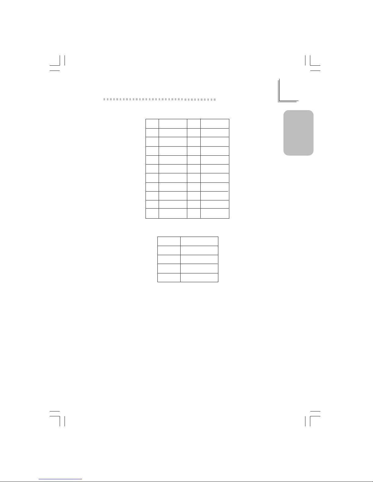
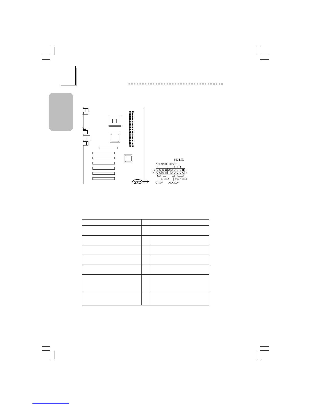
1.3.17 Front Panel Connectors
Front panel
connectors (J20)
If a system did not boot-up and the Power/Standby LED did not light after it
was powered-on, it may indicate that the CPU or memor y module was not
installed properly. Please make sure they are properly inserted into their
corresponding socket.
Pin
3
5
14
16
8
10
18
20
7
9
13
15
17
19
2
4
6
HD-LED
(Primary/Secondary IDE LED)
G-LED
(Green LED)
ATX-SW
(ATX power switch)
G-SW
(Green switch)
RESET
(Reset switch)
SPEAKER
(Speaker connector)
PWR-LED
(Power/Standby LED)
Pin Assignment
HDD LED Power
HDD
Green LED Power
Ground
PWRBT+
PWRBT-
Ground
SMI
Ground
H/W Reset
Speaker Data
N. C.
Ground
Speaker Power
LED Power (+)
LED Power (+)
LED Power (-) or Standby Signal

27
1
Quick Setup Guide
Quick Setup
Guide
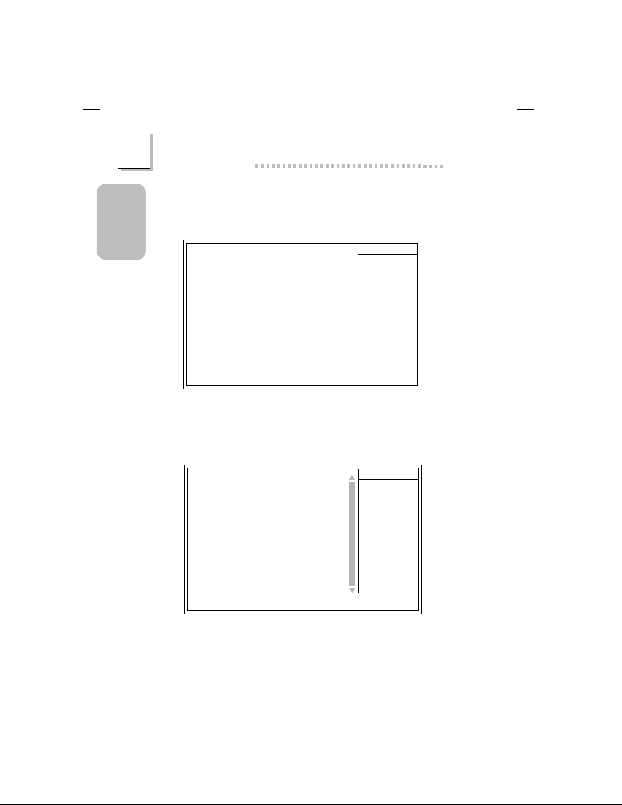
1.4 Award BIOS Setup Utility
1.4.1 Main Menu
1.4.2 Standard CMOS Features
Phoenix - AwardBIOS CMOS Setup Utility
Standard CMOS Features
Advanced BIOS Features
Advanced Chipset Features
Integrated Peripherals
Power Management Setup
PnP/PCI Configurations
CPU Frequency/Voltage Control
Load Fail-Safe Defaults
Load Optimized Defaults
Set Supervisor Password
Set User Password
Save & Exit Setup
Exit Without Saving
Esc
F10
: Quit
: Save & Exit Setup
↑↓→←
: Select Item
Time, Date, Hard Disk Type...
!
!
!
!
!
!
!
The settings on the screen are for reference only. Your version may not be
identical to this one.
↑↓→← Move
Phoenix - AwardBIOS CMOS Setup Utility
Standard CMOS Features
Date (mm:dd:yy)
Time (hh:mm:ss)
IDE Primary Master
IDE Primary Slave
IDE Secondary Master
IDE Secondary Slave
Drive A
Drive B
Video
Halt On
Base Memory
Extended Memory
Total Memory
F6:Fail-Safe Defaults F7:Optimized Defaults
F1:General Help
Fri, Jul 5 2002
4 : 35 : 5
Press Enter None
Press Enter None
Press Enter None
Press Enter None
1.44M, 3.5 in.
None
EGA/VGA
All, But Keyboard
640K
129024K
130048K
Item Help
Menu Level
Change the day, month,
year and century
Enter:Select
F5:Previous V alues
+/-/PU/PD:Value F10:Save ESC:Exit
!
!
!
!
28
Quick Setup Guide
1
Quick Setup
Guide
1.4.4 Advanced BIOS Features
1.4.3 IDE Primary Master, IDE Primar y Slave, IDE Secondar y
Master and IDE Secondary Slave
The settings on the screen are for reference only. Your ver sion may not be
identical to this one.
↑↓→← :Move
Phoenix - AwardBIOS CMOS Setup Utility
IDE Primary Master
IDE HDD Auto Detection
IDE Primary Master
Access Mode
Capacity
Cylinder
Head
Precomp
Landing Zone
Sector
F6:Fail-Safe Defaults F7:Optimized Defaults
F1:General Help
Press Enter
Auto
Auto
0 M
0
0
0
0
Item Help
Menu Level
Change the day, month,
year and century
Enter:Select
F5:Previous Values
+/-/PU/PD:Value F10:Save ESC:Exit
Phoenix - AwardBIOS CMOS Setup Utility
Advanced BIOS Features
Item Help
Menu Level
Allows you to choose
the VIRUS warning
feature for IDE Hard
Disk boot sector
protection. If this
function is enabled and
someone attempt to
write data into this
area, BIOS will show a
warning message on
screen and alarm beep
↑↓→← Move
F6:Fail-Safe Defaults F7:Optimized Defaults
F1:General HelpEnter:Select
F5:Previous Values
+/-/PU/PD:Value
F10:Save
ESC:Exit
X
X
BIOS Flash Protect
Virus Warning
CPU L1 & L2 Cache
Quick Power On Self Test
First Boot Device
Second Boot Device
Third Boot Device
Boot Other Device
Swap Floppy Drive
Boot Up Floppy Seek
Boot Up NumLock Status
Typematic Rate Setting
Typematic Rate (Chars/Sec)
Typematic Delay (Msec)
Security Option
APIC Mode
MPS Version Control For OS
OS Select For DRAM > 64MB
HDD S.M.A.R.T. Capability
Full Screen Logo Show
Small Logo (EPA) Show
Disabled
Disabled
Enabled
Enabled
Floppy
CDROM
HDD-0
Enabled
Disabled
Disabled
On
Disabled
6
250
Setup
Enabled
1.4
Non-OS2
Disabled
Enabled
Enabled
The screen above list all the fields available in the Advanced BIOS Features
submenu, for ease of reference in this manual. In the actual CMOS setup,
you have to use the scroll bar to view the fields. The settings on the screen
are for reference only. Your version may not be identical to this one.

29
1
Quick Setup Guide
Quick Setup
Guide
1.4.5 Advanced Chipset Features
The settings on the screen are for reference only. Your version may not be
identical to this one.
Phoenix - AwardBIOS CMOS Setup Utility
Advanced Chipset Features
DRAM Timing Selectable
CAS Latency Time
Active to Precharge Delay
DRAM RAS# to CAS# Delay
DRAM RAS# Precharge
Memory Frequency For
System BIOS Cacheable
Video BIOS Cacheable
Delayed Transaction
AGP Aperture Size (MB)
AGP 4X Mode
On-Chip Video Windows Size
On-Chip Frame Buffer Size
By User
3
7
3
3
Auto
Disabled
Disabled
Enabled
64
Enabled
128MB
1MB
Item Help
Menu Level
↑↓→← Move
F6:Fail-Safe Defaults F7:Optimized Defaults
F1:General HelpEnter:Select
F5:Previous Values
+/-/PU/PD:Value F10:Save ESC:Exit
1.4.6 Integrated Peripherals
Phoenix - AwardBIOS CMOS Setup Utility
Integrated Peripherals
The settings on the screen are for reference only. Your version may not be
identical to this one.
INTEL OnChip IDE Device
INTEL OnChip PCI Device
Onboard Super IO Device
USB Controller
USB Keyboard Support
USB Mouse Support
Init Display First
Press Enter
Press Enter
Press Enter
Enabled
Enabled
Disabled
Onboard/AGP
Item Help
Menu Level
↑↓→← Move
F6:Fail-Safe Defaults F7:Optimized Defaults
F1:General HelpEnter:Select
F5:Previous Values
+/-/PU/PD:Value
F10:Save
ESC:Exit
!
!
!

30
Quick Setup Guide
1
Quick Setup
Guide
1.4.7 INTEL OnChip IDE Device
Phoenix - AwardBIOS CMOS Setup Utility
INTEL OnChip IDE Device
The settings on the screen are for reference only. Your version may not be
identical to this one.
Item Help
Menu Level
↑↓→← Move
F6:Fail-Safe Defaults F7:Optimized Defaults
F1:General HelpEnter:Select
F5:Previous Values
+/-/PU/PD:Value F10:Save ESC:Exit
On-Chip Primary PCI IDE
IDE Primary Master PIO
IDE Primary Slave PIO
IDE Primary Master UDMA
IDE Primary Slave UDMA
On-Chip Secondary PCI IDE
IDE Secondary Master PIO
IDE Secondary Slave PIO
IDE Secondary Master UDMA
IDE Secondary Slave UDMA
IDE HDD Block Mode
Enabled
Auto
Auto
Auto
Auto
Enabled
Auto
Auto
Auto
Auto
Enabled
1.4.8 INTEL OnChip PCI Device
Phoenix - AwardBIOS CMOS Setup Utility
INTEL OnChip PCI Device
Item Help
Menu Level
↑↓→← Move
F6:Fail-Safe Defaults F7:Optimized Defaults
F1:General HelpEnter:Select
F5:Previous Values
+/-/PU/PD:Value
F10:Save
ESC:Exit
AC97 Audio
Onboard LAN Control
Auto
Enabled
 Loading...