

Page 1

NB76-BC
NB76-BL
Rev. A+
System Board User’s Manual
Carte Mère Manuel Pour Utilisateur
System-Platine Benutzerhandbuch
Manual del Usuario de Placas Base
935-NB7601-300
62300231
Page 2

Copyright
This publication contains information that is protected by copyright.
No par t of it may be reproduced in any form or by any means or
used to make any transformation/adaptation without the prior
written permission from the copyright holders.
This publication is provided for informational purposes only. The
manufacturer makes no representations or warranties with respect to
the contents or use of this manual and specifically disclaims any
express or implied warranties of merchantability or fitness for any
par ticular purpose . The user will assume the entire risk of the use or
the results of the use of this document. Further, the manufacturer
reserves the r ight to revise this publication and make changes to its
contents at any time, without obligation to notify any person or
entity of such revisions or changes.
© 2002. All Rights Reserved.
Trademarks
Windows® 98 SE, Windows® ME, Windows® 2000, Windows NT
®
4.0 and Windows® XP are registered trademarks of Microsoft
Corporation. Intel® and Pentium® 4 are registered trademarks of
Intel Corporation. Award is a registered trademark of Award
Software, Inc. Other trademarks and registered trademarks of
products appearing in this manual are the properties of their
respective holders.
Caution
To avoid damage to the system:
• Use the correct AC input voltage r ange
..
..
.
To reduce the risk of electr ic shock:
• Unplug the power cord before removing the system chassis
cover for installation or servicing. After installation or ser vicing,
cover the system chassis before plugging the power cord.
Page 3

Battery:
• Danger of explosion if batter y incor rectly replaced.
• Replace only with the same or equivalent type recommend
by
the manufacturer.
• Dispose of used batteries according to the battery
manufacturer’s
instructions.
Joystick or MIDI por t:
• Do not use any joystick or MIDI device that requires more than
10A current at 5V DC. There is a risk of fire for devices that
exceed this limit.
FCC and DOC Statement on Class B
This equipment has been tested and found to comply with the limits
for a Class B digital device, pursuant to Par t 15 of the FCC rules.
These limits are designed to provide reasonable protection against
harmful interference when the equipment is operated in a residential
installation. This equipment generates, uses and can radiate radio
frequency energy and, if not installed and used in accordance with
the instruction manual, may cause harmful interference to radio
communications. However, there is no guarantee that interference
will not occur in a par ticular installation. If this equipment does cause
harmful interference to radio or television reception, which can be
determined by turning the equipment off and on, the user is
encouraged to tr y to correct the interference by one or more of the
following measures:
• Reorient or relocate the receiving antenna.
• Increase the separation between the equipment and the receiver.
• Connect the equipment into an outlet on a circuit different from
that to which the receiver is connected.
• Consult the dealer or an experienced radio TV technician for
help.
Notice:
1. The changes or modifications not expressly approved by the
par ty responsible for compliance could void the user's authority
to operate the equipment.
2. Shielded interface cables must be used in order to comply with
the emission limits.
Page 4

4
Quick Setup Guide
1
Quick Setup
Guide
Table of Contents
Chapter 1
Quick Setup Guide.............................................
Chapter 2
English......................................................................
Chapter 3
Français (French).................................................
Chapter 4
Deutsch (German)................................................
Chapter 5
Español (Spanish)..................................................
5
35
50
67
84
NB76-BC/BL Intel 845G
AGP slot
“BL” supports onboard LAN and Smar t I/O
Page 5

5
1
Quick Setup Guide
Quick Setup
Guide
Chapter 1 - Quick Setup Guide
Table of Contents
1.1 System Board Layout..................................................................................................
1.2 Jumpers.....................................................................................................................................
1.3 Por ts and Connector s................................................................................................
1.4 Award BIOS Setup Utility.......................................................................................
6
9
12
27
Note:
The user’s manual in the provided CD contains detailed information
about the system board. If, in some cases, some information doesn’t
match those shown in this manual, this manual should always be
regarded as the most updated version.
Page 6
6
Quick Setup Guide
1
Quick Setup
Guide
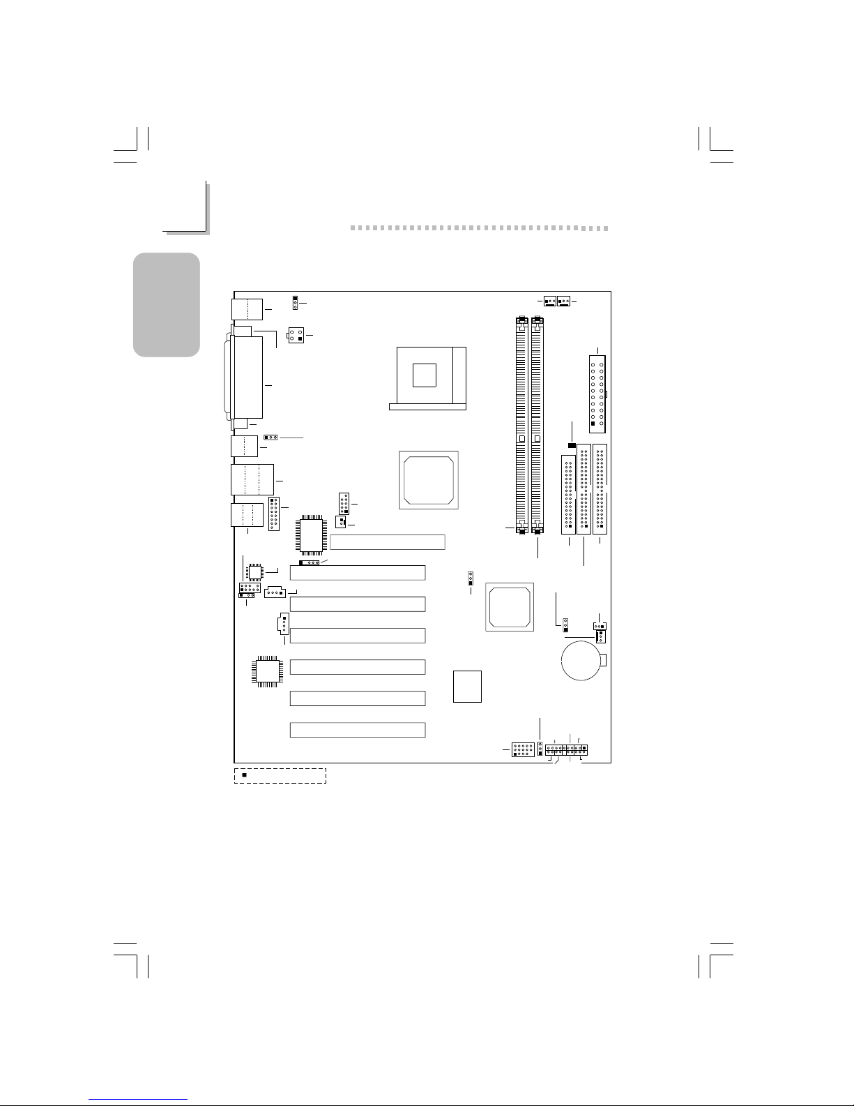
1.1 System Board Layout
KB
Mouse
CN4
COM 1
(CN2)
Parallel (CN6)
VGA (CN1)
Wake-On-KB/Mouse
(JP1)
+12V power
(ATXP1)
4
321
CN3
USB 1
USB 2
LAN
USB 3
USB 4
CN7
Line-out
Line-in
Mic-in
CN5
Game/MIDI
(J6)
1
2
15
1
2
9
I/O
chip
IrDA (J11)
AC’97
Front audio (J2)
Realtek
RTL8100
Socket 478
DDR SDRAM
DIMM 1
DDR SDRAM
DIMM 2
Intel
845G
GMCH
Intel
ICH4
CPU FSB
select (JP4)
Clear CMOS (JP7)
Wake-On-
LAN (J23)
Chassis
fan (J25)
Battery
CPU fan
(J18)
Second
fan (J19)
ATX main
power (PL1)
DIMM
Standby
Power LED
FDD (J21)
IDE 2 (J22)
IDE 1
(J24)
Firmware
Hub
J20
PWR-LED
G-SW
RESET
SPEAKER
G-LED
HD-LED
Square denotes pin 1
ATX-SW
AGP Slot
PCI Slot 1
PCI Slot 2
PCI Slot 3
PCI Slot 4
PCI Slot 5
PCI Slot 6
CN3
Wake-On-USB KB
for USB 1/2/3/4 (JP9)
COM 2
(J13)
Wake-On-Ring (J12)
USB 5 & 6
(J14)
Wake-On-USB KB for
USB 5/6 (JP8)
CD-in (J8)
TAD (J7)
S/PDIF-out
(J1)
NB76-BL
(Supports onboard LAN)
Page 7
7
1
Quick Setup Guide
Quick Setup
Guide
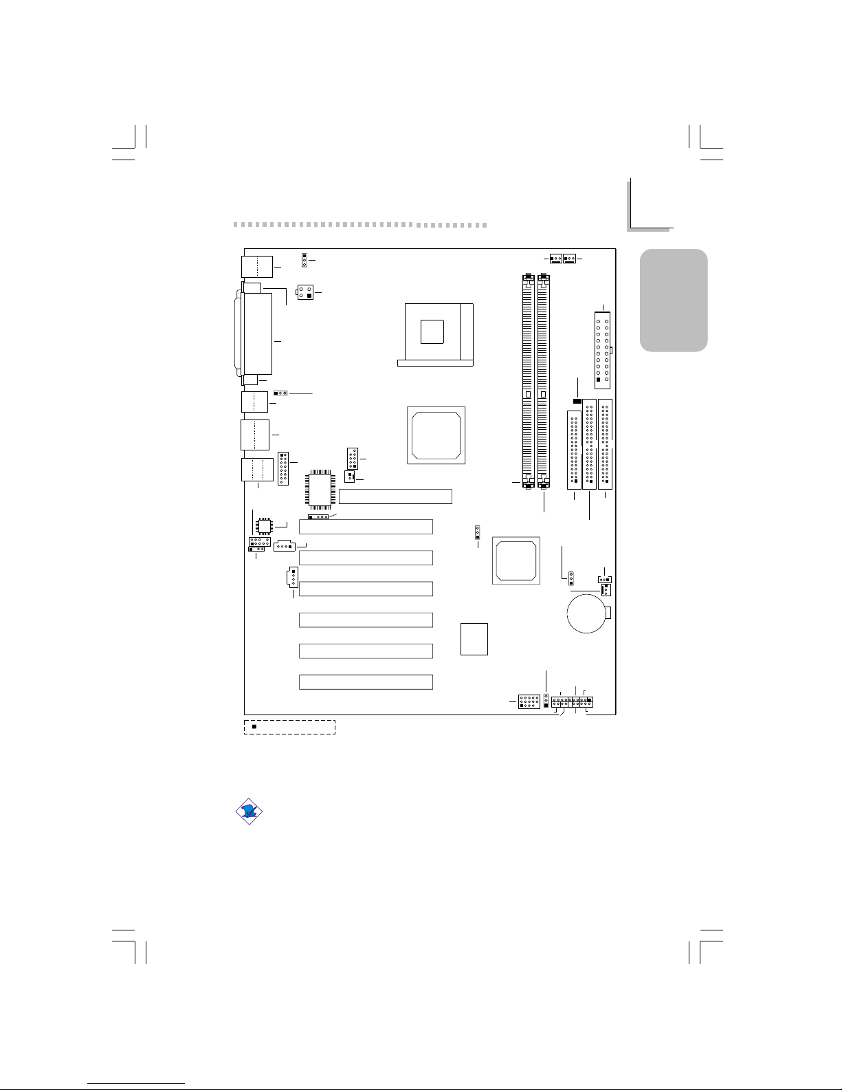
Note:
The illustrations on the following pages are based on the system
board that supports onboard LAN.
KB
Mouse
CN4
COM 1
(CN2)
Parallel (CN6)
VGA (CN1)
Wake-On-KB/Mouse
(JP1)
+12V power
(ATXP1)
4
321
CN3
USB 1
USB 2
USB 3
USB 4
CN7
Line-out
Line-in
Mic-in
CN5
Game/MIDI
(J6)
1
2
15
1
2
9
I/O
chip
IrDA (J11)
AC’97
Front audio (J2)
Socket 478
DDR SDRAM
DIMM 1
DDR SDRAM
DIMM 2
Intel
845G
GMCH
Intel
ICH4
CPU FSB
select (JP4)
Clear CMOS (JP7)
Wake-On-
LAN (J23)
Chassis
fan (J25)
Battery
CPU fan
(J18)
Second
fan (J19)
ATX main
power (PL1)
DIMM
Standby
Power LED
FDD (J21)
IDE 2 (J22)
IDE 1
(J24)
Firmware
Hub
J20
PWR-LED
G-SW
RESET
SPEAKER
G-LED
HD-LED
Square denotes pin 1
ATX-SW
AGP Slot
PCI Slot 1
PCI Slot 2
PCI Slot 3
PCI Slot 4
PCI Slot 5
PCI Slot 6
CN3
Wake-On-USB KB
for USB 1/2/3/4 (JP9)
COM 2
(J13)
Wake-On-Ring (J12)
USB5&6
(J14)
Wake-On-USB KB for
USB 5/6 (JP8)
CD-in (J8)
TAD (J7)
S/PDIF-out
(J1)
NB76-BC
Page 8

8
Quick Setup Guide
1
Quick Setup
Guide
Warning:
Electrostatic discharge (ESD) can damage your system board,
processor, disk drives, add-in boards, and other components. Perform
the upgrade instruction procedures described at an ESD workstation
only. If such a station is not available, you can provide some ESD
protection by wearing an antistatic wrist strap and attaching it to a
metal part of the system chassis. If a wrist strap is unavailable,
establish and maintain contact with the system chassis throughout
any procedures requiring ESD protection.
Page 9
9
1
Quick Setup Guide
Quick Setup
Guide
1.2 Jumpers
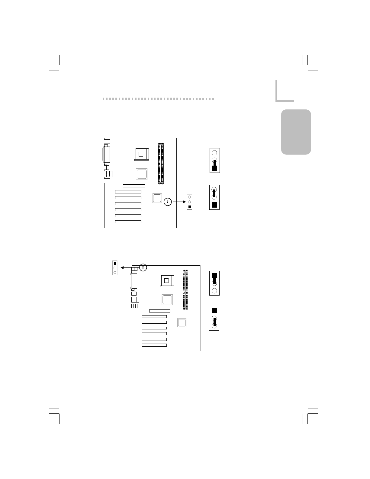
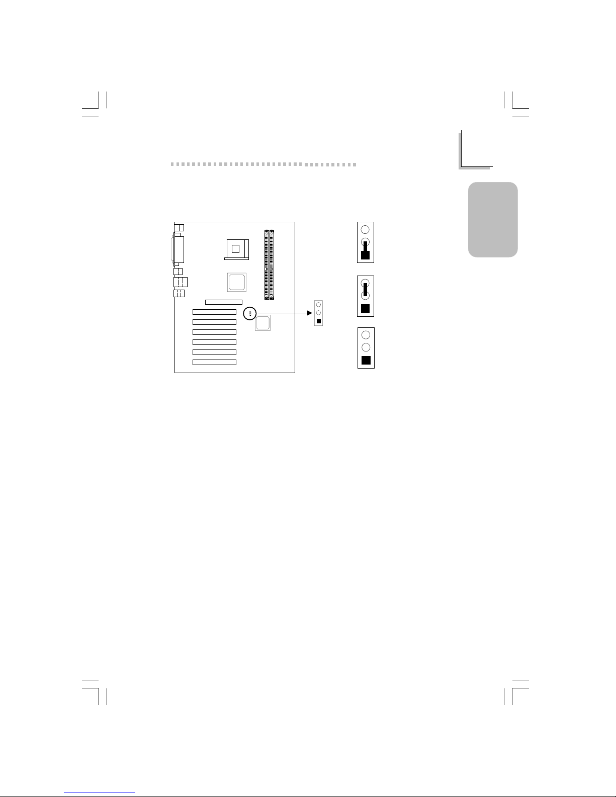
1.2.1 Clear CMOS Data - JP7
3
2
1
3
2
1
1-2 On:
Normal (default)
2-3 On:
Clear CMOS Data
Clear CMOS
(JP7)
1
2
3
1.2.2 Jumper Settings for Wake-On-Keyboard/Wake-OnMouse - JP1
Wake-On-
KB/Mouse (JP1)
1
2
3
1
2
3
1-2 On: Disable
(default)
1
2
3
2-3 On: Enable
If JP1 was enabled with a password set in the “KB Power On Password” field,
and now you wish to disable the keyboard password function, make sure to
set the “Keyboard/Mouse Power On” field to Disabled prior to setting JP1 to
disabled. You will not be able to boot up the system if you fail to do so.
Page 10
10
Quick Setup Guide
1
Quick Setup
Guide
The power button will not function once a keyboard password has been set
in the “KB Power On Password” (“Onboard Super IO Device” field) of the
Integrated Peripherals submenu. You must type the correct password to
power-on the system.
The 5VSB power source of your power supply must support ≥720mA.
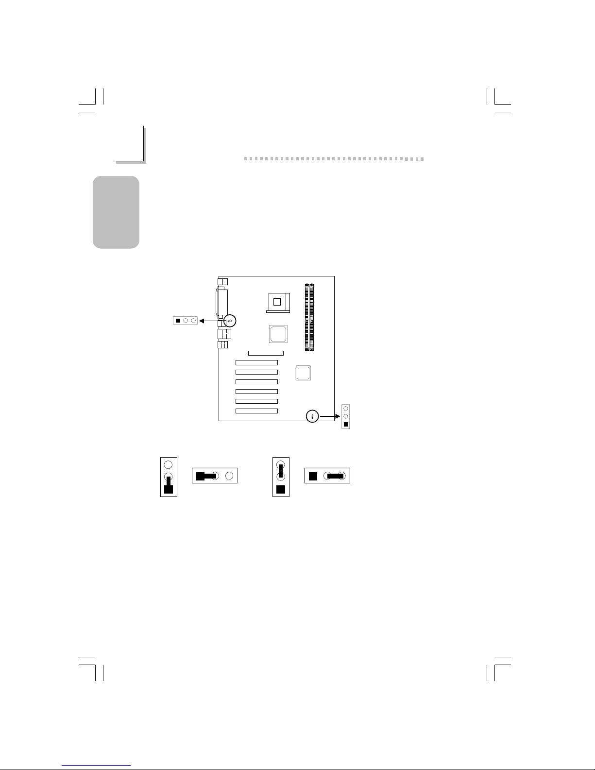
1.2.3 Jumper Settings for Wake-On-USB Keyboard
Wake-On-USB (KB)
1/2/3/4 (JP9)
Wake-On-USB
(KB) 5/6 (JP8)
1
2
3
12
3
2-3 On: Enable
(default)
1-2 On: Disable
123
JP8
JP9
3
2
1
123
JP8
JP9
3
2
1
If you are using the Wake-On-USB Keyboard function for 2 USB ports, the
5VSB power source of your power supply must support ≥1.5A.
If you are using the Wake-On-USB Keyboard function for 4 or more USB
ports, the 5VSB power source of your power supply must support ≥2A.
Page 11
11
1
Quick Setup Guide
Quick Setup
Guide
1.2.4 Jumper Settings for Selecting the CPU’s Front Side
Bus
CPU FSB select
(JP4)
1
2
3
3
2
1
3
2
1
3
2
1
1-2 On: Auto
(default)
2-3 On: 100MHz
All Off: 133MHz
Page 12
12
Quick Setup Guide
1
Quick Setup
Guide
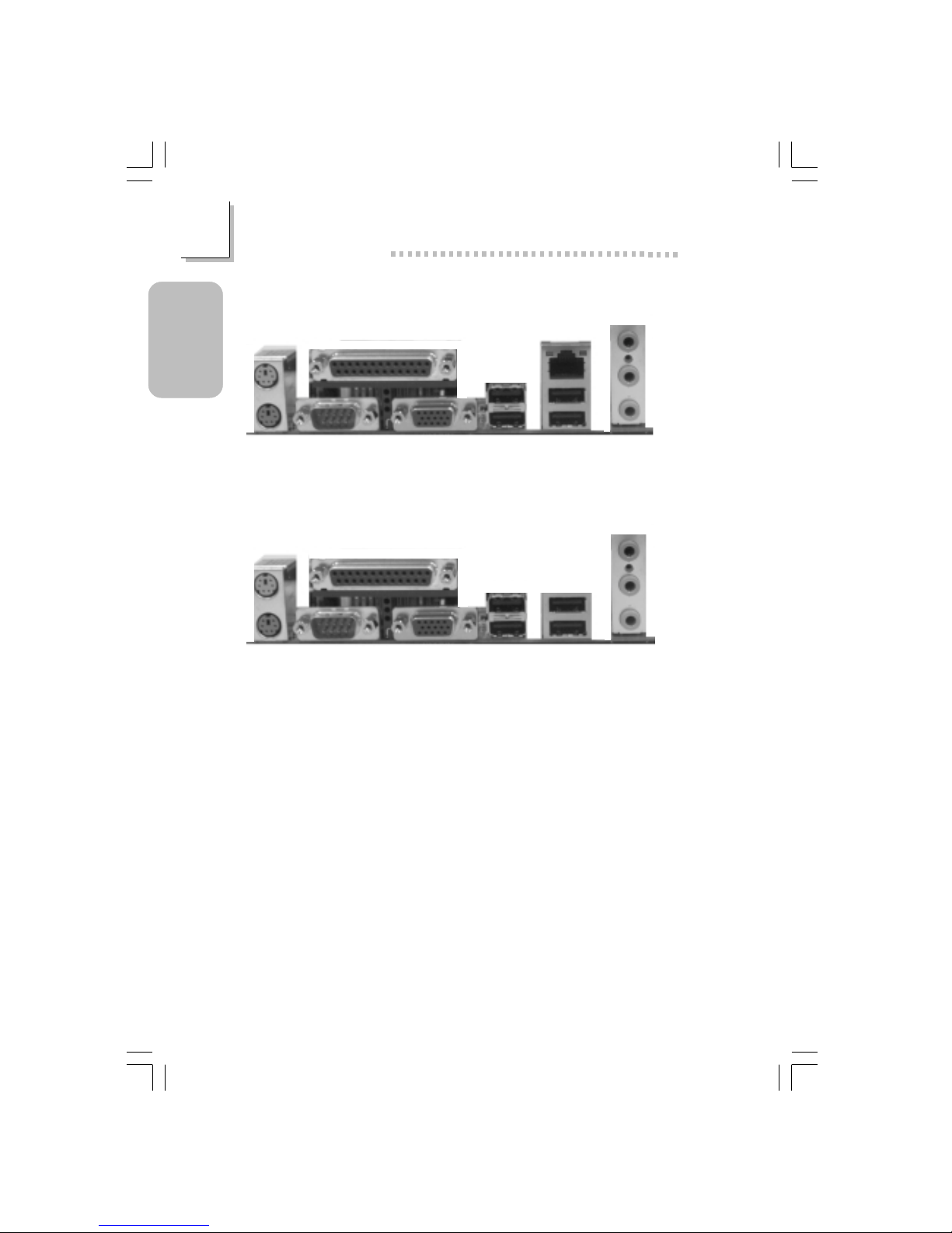
1.3 Ports and Connectors
PS/2
Mouse
PS/2
K/B
RJ45
LAN
USB 4/3COM 1 VGA
Parallel
Line-out
Line-in
Mic-in
USB 1
ATX Double Deck Ports on NB76-BL
PS/2
Mouse
PS/2
K/B
USB 3COM 1 VGA
Parallel
Line-out
Line-in
Mic-in
USB 1
ATX Double Deck Ports on NB76-BC
USB 4
USB 2
USB 2
Page 13
13
1
Quick Setup Guide
Quick Setup
Guide
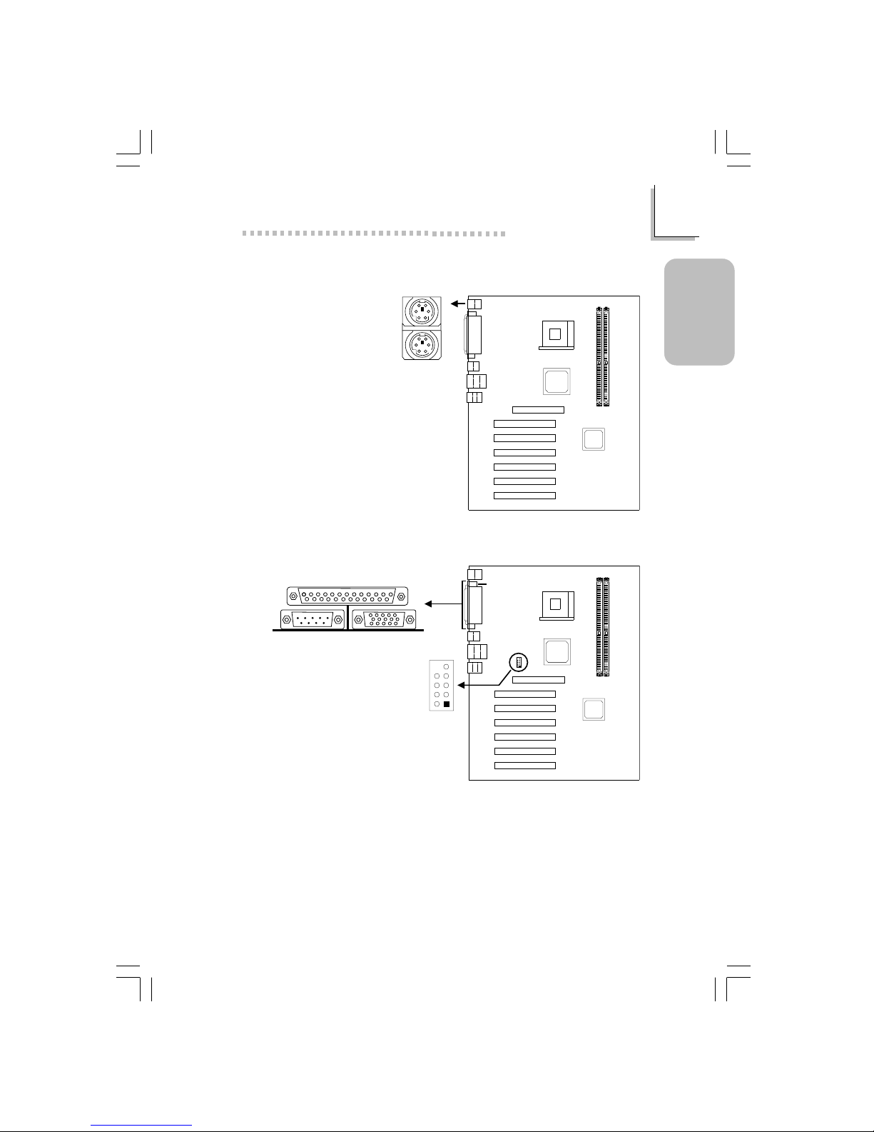
1.3.1 PS/2 Mouse and PS/2 Keyboard Ports
Make sure to turn off your
computer prior to connecting or
disconnecting a mouse or keyboard.
Failure to do so may damage the
system board.
PS/2 Mouse
PS/2 Keyboard
CN4
1.3.2 Serial Ports
CN2
1
2
9
COM 2
(J13)
2
1
9
COM 1
Serial Port
Page 14
14
Quick Setup Guide
1
Quick Setup
Guide
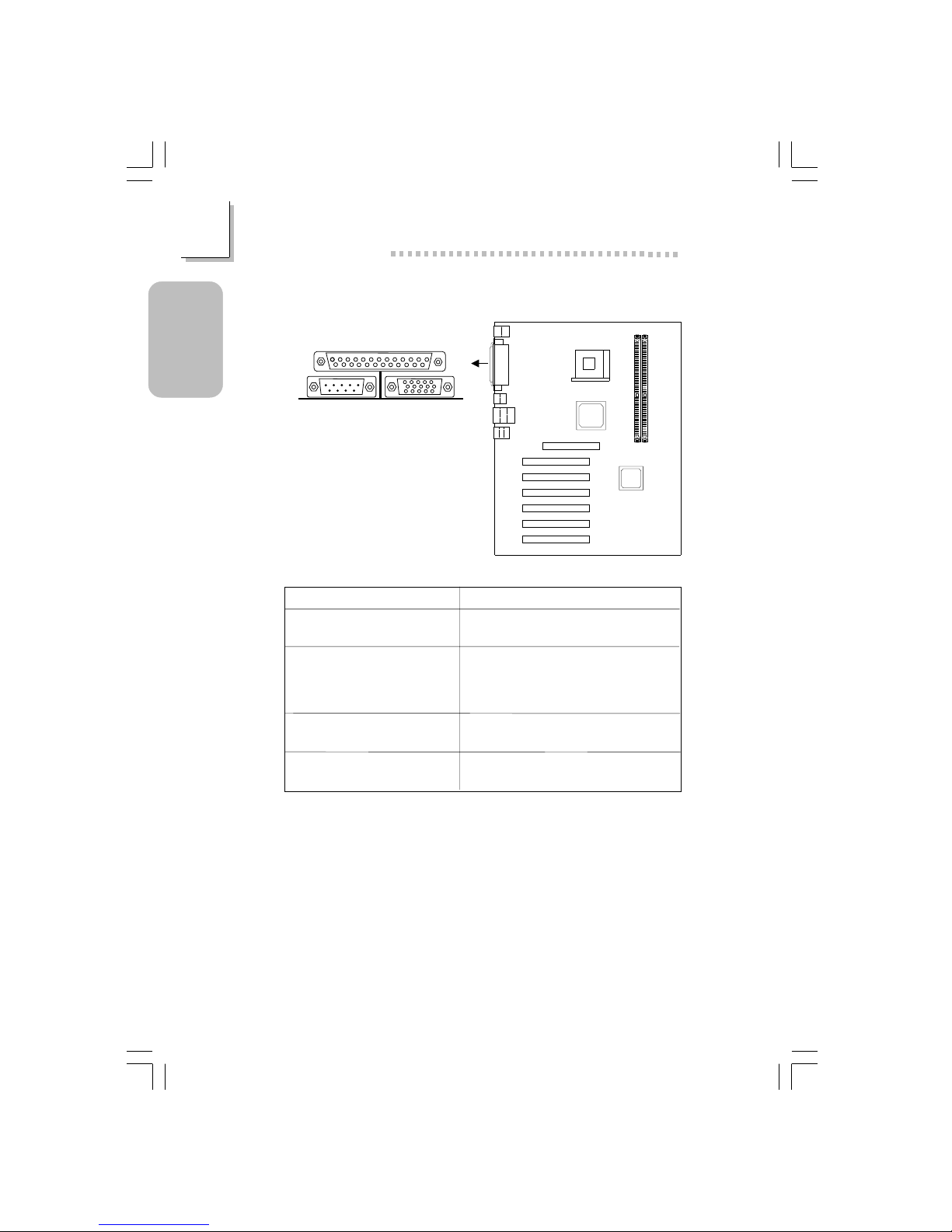
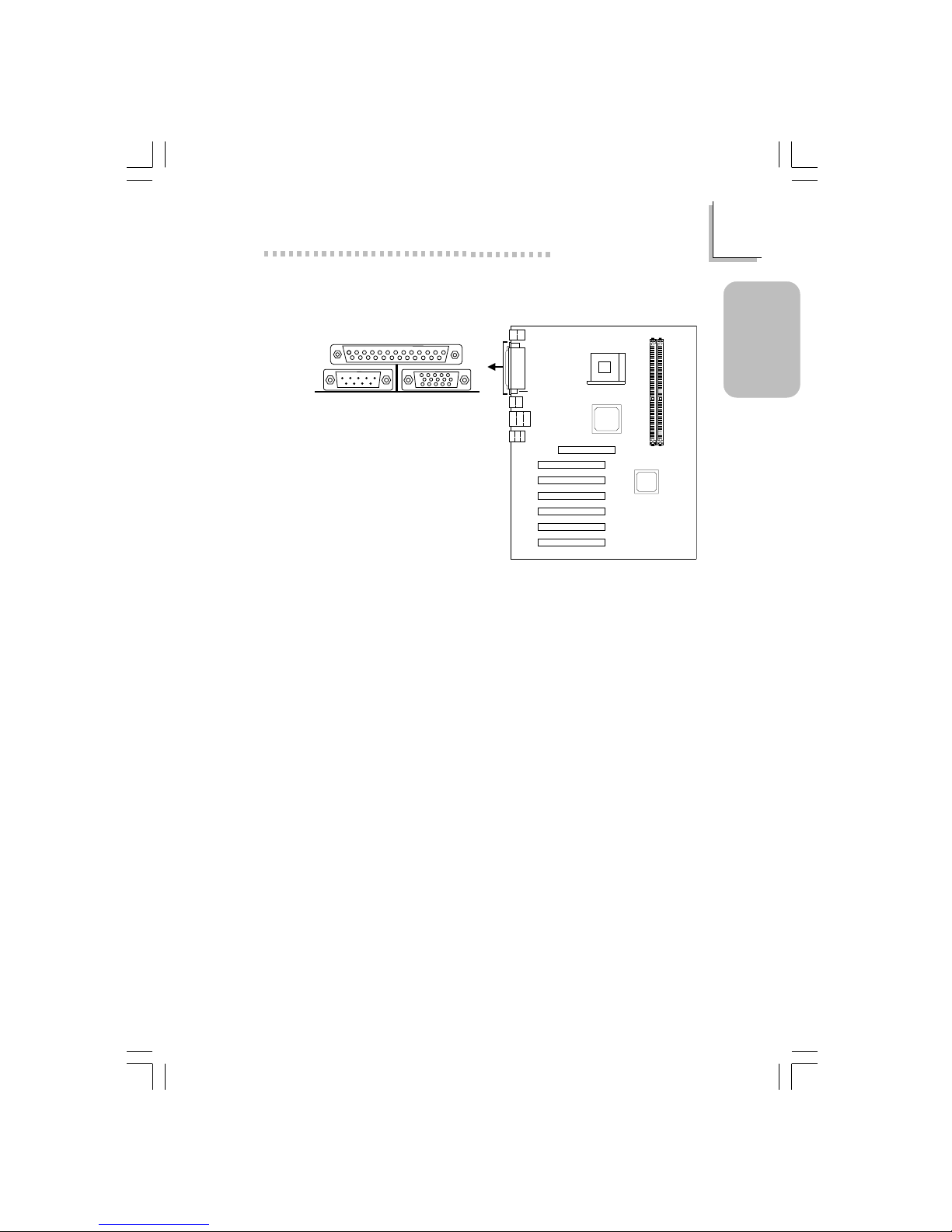
1.3.3 Parallel Port
CN6
Parallel Port
Setting
SPP
(Standard Parallel Port)
ECP
(Extended Capabilities Port)
EPP
(Enhanced Parallel Port)
PntMode
Function
Allows normal speed operation but
in one direction only .
Allows parallel port to operate in
bidirectional mode and at a speed
faster than the SPP’s data transfer
rate.
Allows bidirectional parallel port operation at maximum speed.
Allows parallel port to operate in
bipolar mode.
Page 15
15
1
Quick Setup Guide
Quick Setup
Guide
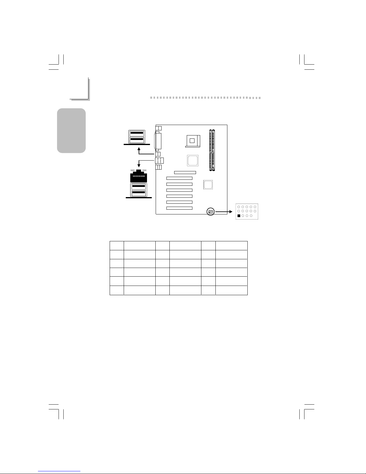
1.3.4 VGA Port
CN1
VGA Por t
Page 16
16
Quick Setup Guide
1
Quick Setup
Guide
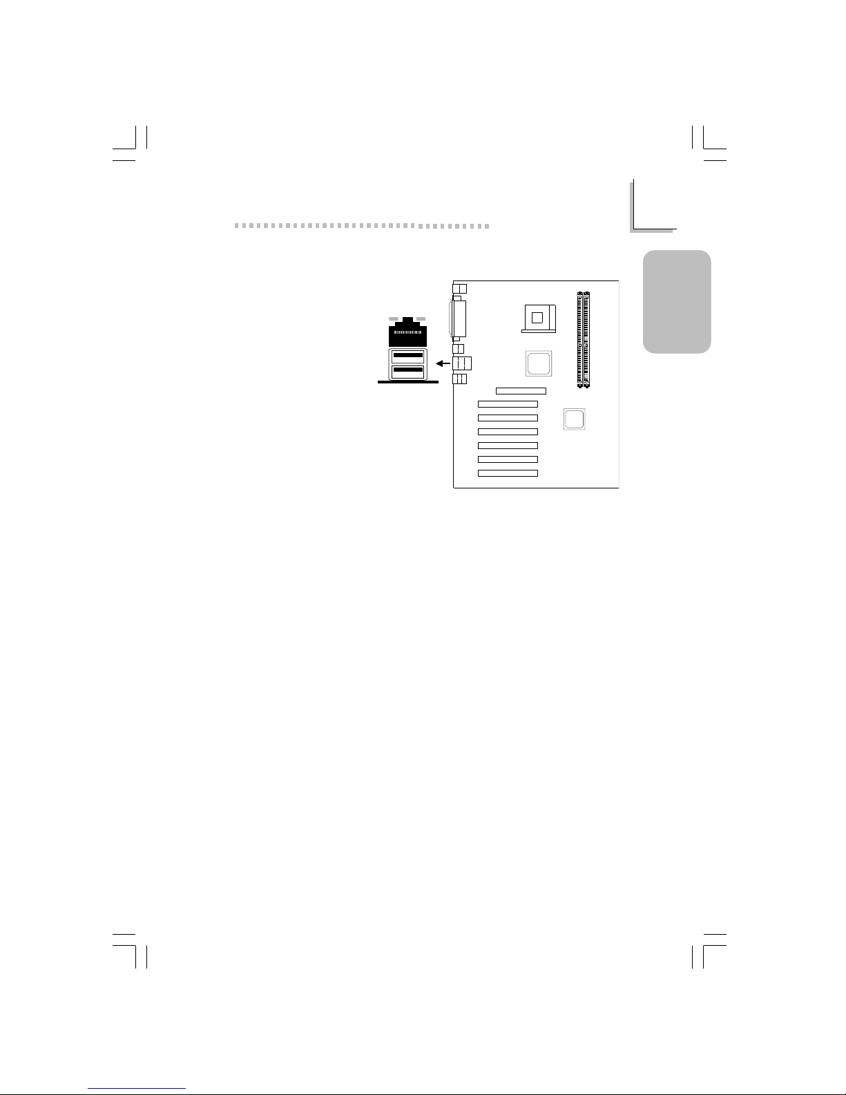
1.3.5 Universal Serial Bus Ports
CN3
CN7
5
15
11
1
USB5&6(J14)
USB 1
USB 4
USB 3
USB 2
Pin
1
2
3
4
5
Function
VCC
UP5-
UP5+
Ground
Key
Pin
6
7
8
9
10
Function
VCC
UP6-
UP6+
Ground
Ground
Pin
11
12
13
14
15
Function
Ground
Ground
UP5+
UP5VCC
Additional USB Ports (USB 5 and USB 6)
Page 17
17
1
Quick Setup Guide
Quick Setup
Guide
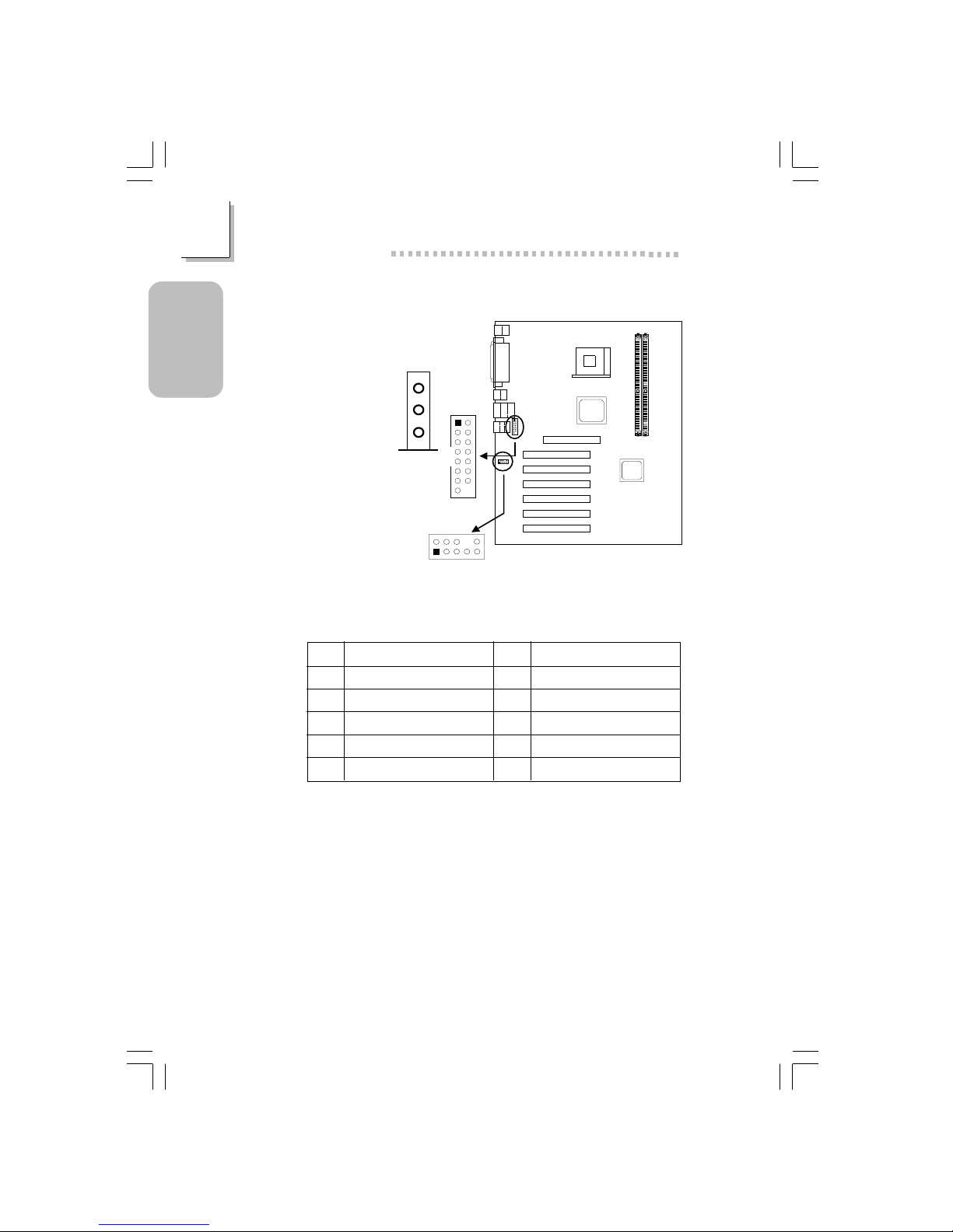
1.3.6 RJ45 Fast-Ethernet Port (NB76-BL only)
CN7
RJ45 LAN
Page 18
18
Quick Setup Guide
1
Quick Setup
Guide
1.3.7 Audio Jacks and Game/MIDI por ts
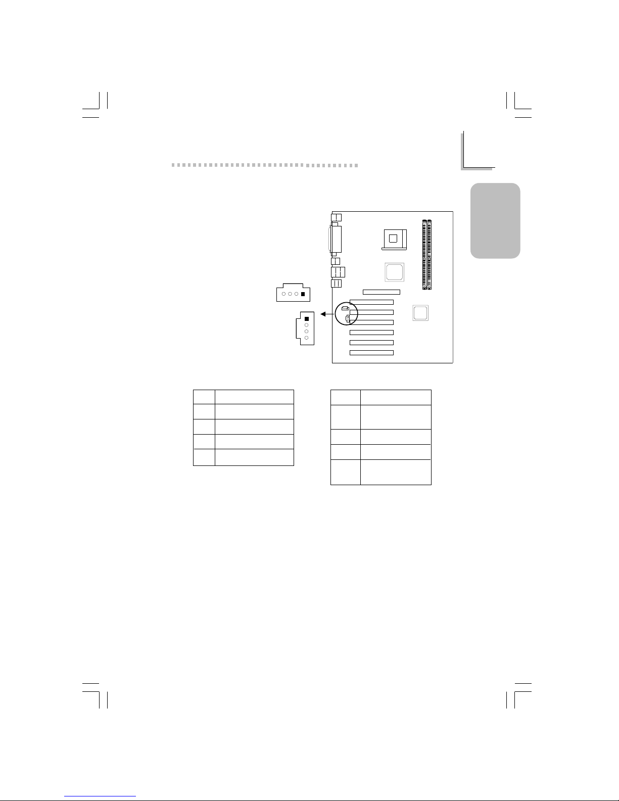
Front Audio (J2)
Pin
1
3
5
7
9
Function
Mic+
Vbias
AuD_R_Out
N. C .
AuD_L_Out
Function
Ground
AuD_Vcc (Avcc)
N. C.
Key
N. C.
Pin
2
4
6
8
10
Game/MIDI
(J6)
1
2
15
2
15
1
Front audio
(J2)
2
1
10
9
Line-out
Line-in
Mic-in
Page 19
19
1
Quick Setup Guide
Quick Setup
Guide
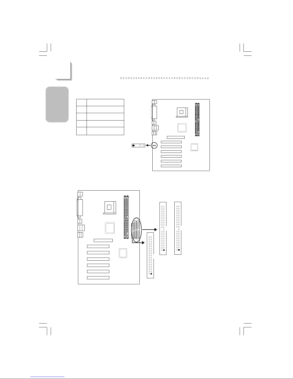
1.3.8 Internal Audio Connectors
4
3
2
1
CD-in (J8)
TAD (J7)
4
3
2
1
Pin
1
2
3
4
Function
Left audio channel
Ground
Ground
Right audio channel
Pin
1
2
3
4
Function
Modem-out
(from modem)
Ground
Ground
Modem-in
(to modem)
CD-in TAD
Page 20
20
Quick Setup Guide
1
Quick Setup
Guide
1.3.9 S/PDIF-out Connector
S/PDIF-out
(J1)
1234
Pin
1
2
3
4
Function
AVDD5
N. C .
SPDIF-out
Ground
1.3.10 Floppy & IDE Disk Drive Connector
IDE 2 (J22)
IDE 1 (J24)
1
2
40
39
1
2
40
39
FDD (J21)
1
2
33
34
If you encountered problems while using an ATAPI CD-ROM drive that is set
in Master mode, please set the CD-ROM drive to Slave mode. Some ATAPI
CD-ROMs may not be recognized and cannot be used if incorrectly set in
Master mode.
Page 21

21
1
Quick Setup Guide
Quick Setup
Guide
1.3.11 IrDA Connector
IrDA (J11)
1234
5
Pin
1
2
3
4
5
Function
VCC
N. C.
IRRX
Ground
IRTX
The sequence of the pin functions on some IrDA cable may be reversed
from the pin function defined on the system board. Make sure to connect
the cable to the IrDA connector according to their pin functions.
Page 22
22
Quick Setup Guide
1
Quick Setup
Guide
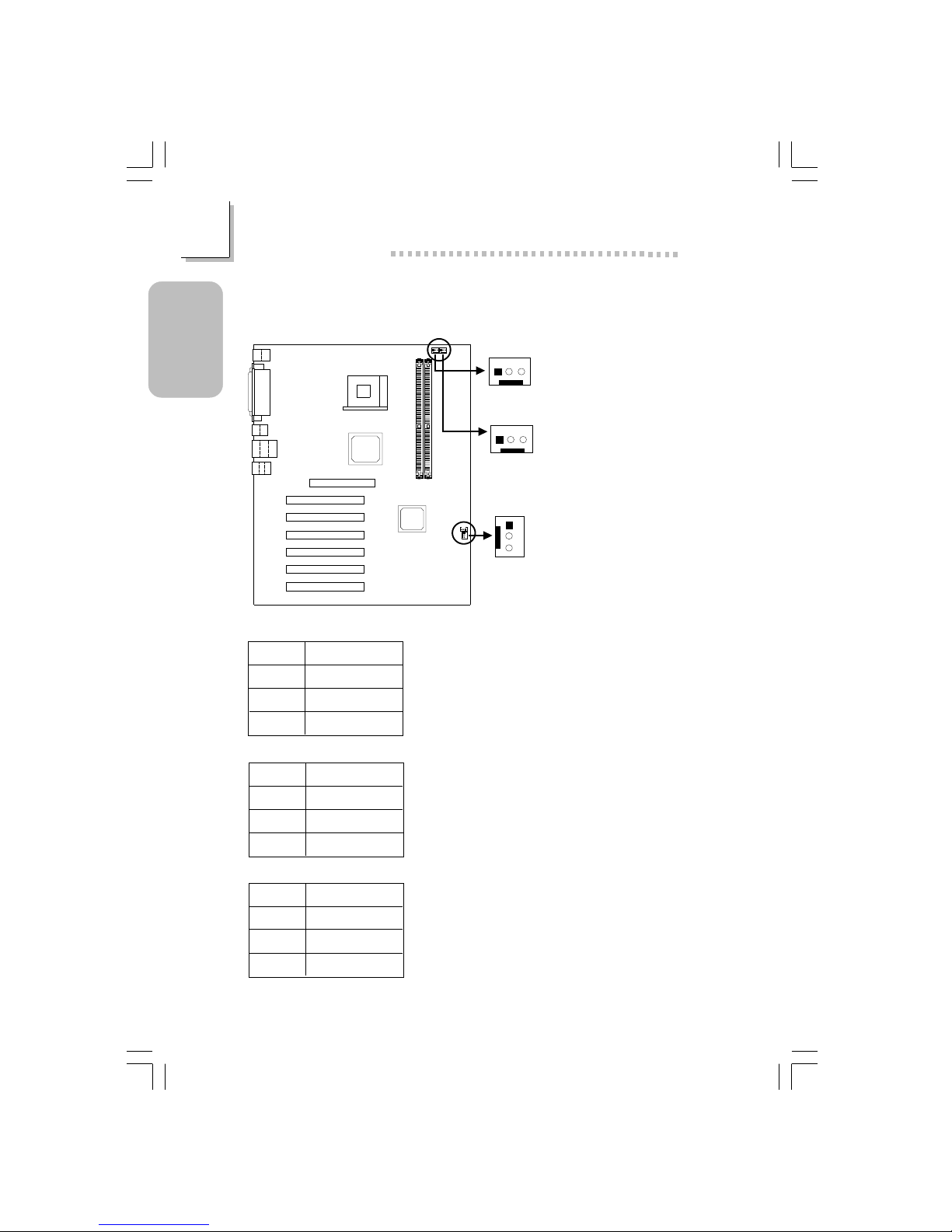
CPU fan
(J18)
3
2
1
Chassis fan
(J25)
3
2
1
Second fan
(J19)
3
2
1
Pin
1
2
3
Function
Ground
Power
N. C.
Pin
1
2
3
Function
Ground
Power
N. C.
Pin
1
2
3
Function
Ground
Power
N. C.
1.3.12 CPU Fan, Chassis Fan and Second Chassis fan
Connector
Page 23
23
1
Quick Setup Guide
Quick Setup
Guide
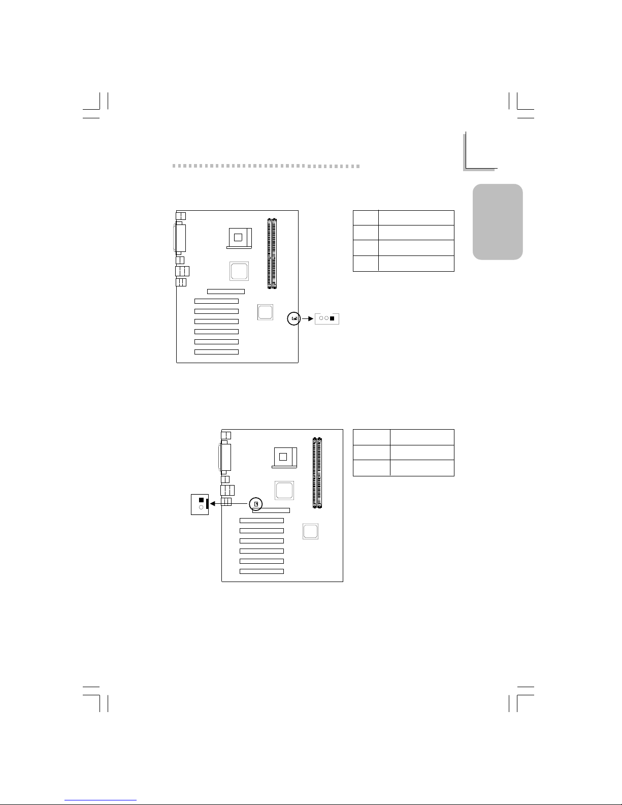
1.3.13 Wake-On-LAN Connector
Wake-On-LAN
(J23)
3
2
1
Pin
1
2
3
Function
WOL
Ground
+5VSB
The 5VSB power source of your power supply must support ≥720mA.
1.3.14 Wake-On-Ring Connector
Wake-On-Ring
(J12)
2
1
Pin
1
2
Function
Ground
RI#
If you are using a modem add-in card, the 5VSB power source of your
power supply must support ≥720mA.
Page 24
24
Quick Setup Guide
1
Quick Setup
Guide
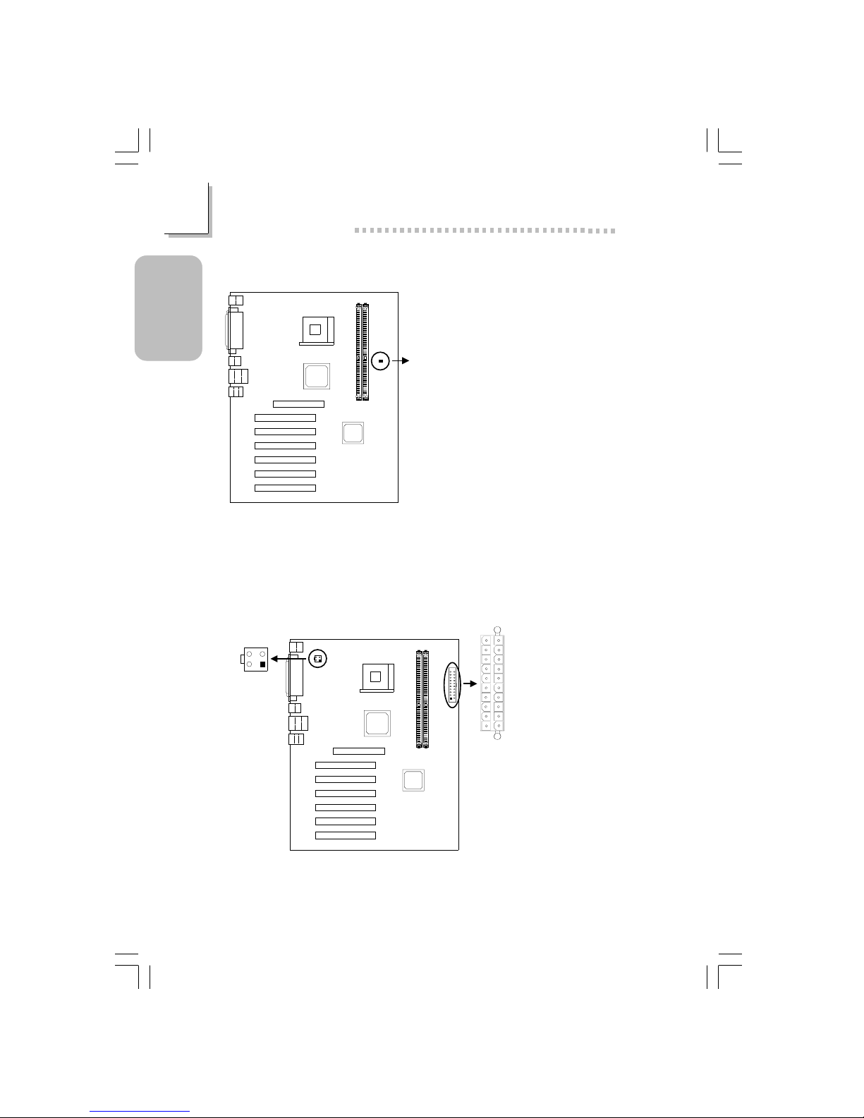
1.3.15 DIMM Standby Power LED
DIMM Standby
Power LED
Lighted LED ser ves as a reminder that you must power-off the system then
turn off the power supply’s switch or unplug the power cord prior to
installing any memor y modules.
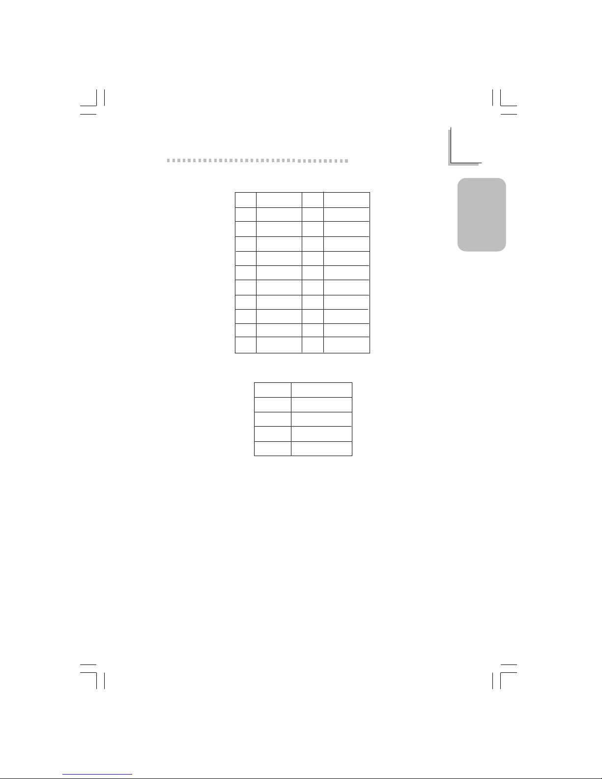
1.3.16 Power Connectors
ATX main
power (PL1)
+12V power
(ATXP1)
4
321
2
1
3
4
1
10
11
20
Page 25
25
1
Quick Setup Guide
Quick Setup
Guide
Pin
1
2
3
4
5
6
7
8
9
10
Function
3.3V
3.3V
Ground
+5V
Ground
+5V
Ground
PW-OK
5VSB
+12V
Pin
11
12
13
14
15
16
17
18
19
20
Function
3.3V
-12V
Ground
PS-ON
Ground
Ground
Ground
-5V
+5V
+5V
Pin
1
2
3
4
ATX Main Power Connector
Function
Ground
Ground
+12V
+12V
+12V Power Connector
Page 26
26
Quick Setup Guide
1
Quick Setup
Guide
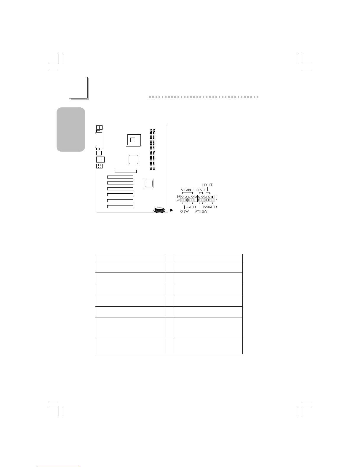
1.3.17 Front Panel Connectors
Front panel
connectors (J20)
If a system did not boot-up and the Power/Standby LED did not light after it
was powered-on, it may indicate that the CPU or memor y module was not
installed properly. Please make sure they are properly inserted into their
corresponding socket.
Pin
3
5
14
16
8
10
18
20
7
9
13
15
17
19
2
4
6
HD-LED
(Primary/Secondary IDE LED)
G-LED
(Green LED)
ATX-SW
(ATX power switch)
G-SW
(Green switch)
RESET
(Reset switch)
SPEAKER
(Speaker connector)
PWR-LED
(Power/Standby LED)
Pin Assignment
HDD LED Power
HDD
Green LED Power
Ground
PWRBT+
PWRBT-
Ground
SMI
Ground
H/W Reset
Speaker Data
N. C.
Ground
Speaker Power
LED Power (+)
LED Power (+)
LED Power (-) or Standby Signal
Page 27

27
1
Quick Setup Guide
Quick Setup
Guide
1.4 Award BIOS Setup Utility
1.4.1 Main Menu
1.4.2 Standard CMOS Features
Phoenix - AwardBIOS CMOS Setup Utility
Standard CMOS Features
Advanced BIOS Features
Advanced Chipset Features
Integrated Peripherals
Power Management Setup
PnP/PCI Configurations
CPU Frequency/Voltage Control
Load Fail-Safe Defaults
Load Optimized Defaults
Set Supervisor Password
Set User Password
Save & Exit Setup
Exit Without Saving
Esc
F10
: Quit
: Save & Exit Setup
↑↓→←
: Select Item
Time, Date, Hard Disk Type...
!
!
!
!
!
!
!
The settings on the screen are for reference only. Your version may not be
identical to this one.
↑↓→← Move
Phoenix - AwardBIOS CMOS Setup Utility
Standard CMOS Features
Date (mm:dd:yy)
Time (hh:mm:ss)
IDE Primary Master
IDE Primary Slave
IDE Secondary Master
IDE Secondary Slave
Drive A
Drive B
Video
Halt On
Base Memory
Extended Memory
Total Memory
F6:Fail-Safe Defaults F7:Optimized Defaults
F1:General Help
Fri, Jul 5 2002
4 : 35 : 5
Press Enter None
Press Enter None
Press Enter None
Press Enter None
1.44M, 3.5 in.
None
EGA/VGA
All, But Keyboard
640K
129024K
130048K
Item Help
Menu Level
Change the day, month,
year and century
Enter:Select
F5:Previous V alues
+/-/PU/PD:Value F10:Save ESC:Exit
!
!
!
!
Page 28
28
Quick Setup Guide
1
Quick Setup
Guide
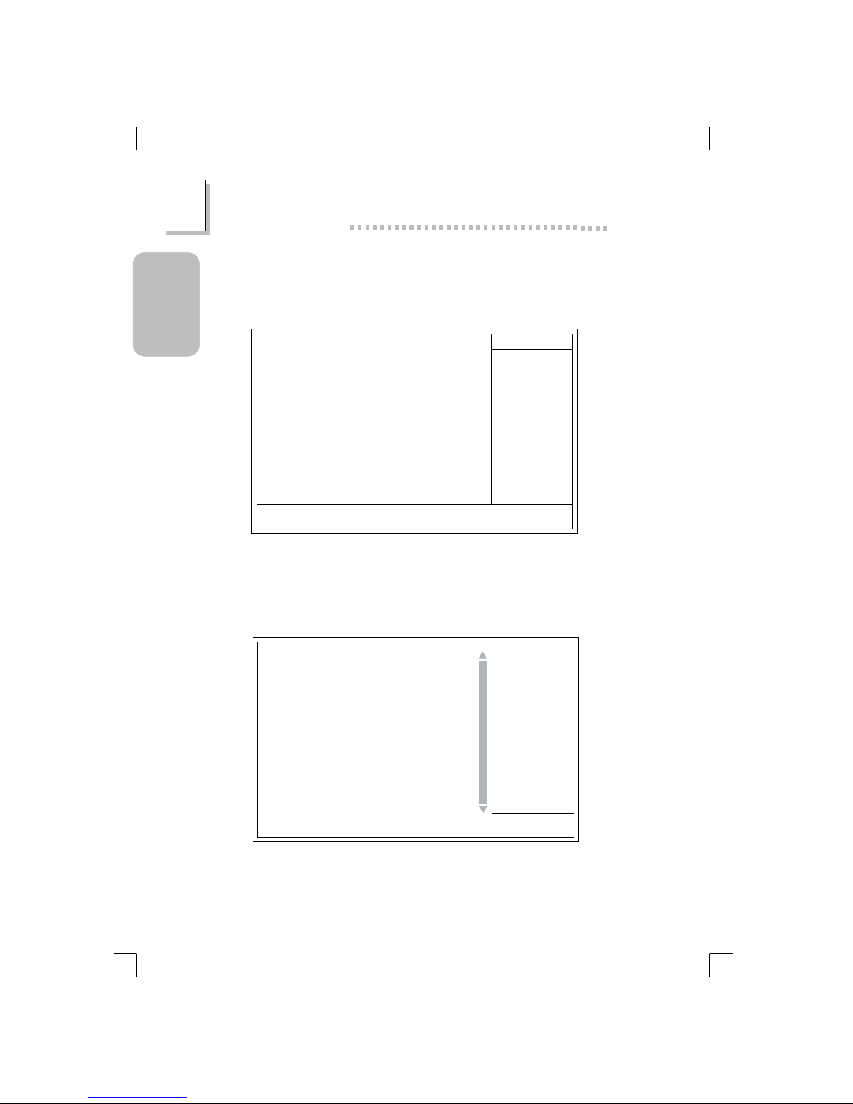
1.4.4 Advanced BIOS Features
1.4.3 IDE Primary Master, IDE Primar y Slave, IDE Secondar y
Master and IDE Secondary Slave
The settings on the screen are for reference only. Your ver sion may not be
identical to this one.
↑↓→← :Move
Phoenix - AwardBIOS CMOS Setup Utility
IDE Primary Master
IDE HDD Auto Detection
IDE Primary Master
Access Mode
Capacity
Cylinder
Head
Precomp
Landing Zone
Sector
F6:Fail-Safe Defaults F7:Optimized Defaults
F1:General Help
Press Enter
Auto
Auto
0 M
0
0
0
0
Item Help
Menu Level
Change the day, month,
year and century
Enter:Select
F5:Previous Values
+/-/PU/PD:Value F10:Save ESC:Exit
Phoenix - AwardBIOS CMOS Setup Utility
Advanced BIOS Features
Item Help
Menu Level
Allows you to choose
the VIRUS warning
feature for IDE Hard
Disk boot sector
protection. If this
function is enabled and
someone attempt to
write data into this
area, BIOS will show a
warning message on
screen and alarm beep
↑↓→← Move
F6:Fail-Safe Defaults F7:Optimized Defaults
F1:General HelpEnter:Select
F5:Previous Values
+/-/PU/PD:Value
F10:Save
ESC:Exit
X
X
BIOS Flash Protect
Virus Warning
CPU L1 & L2 Cache
Quick Power On Self Test
First Boot Device
Second Boot Device
Third Boot Device
Boot Other Device
Swap Floppy Drive
Boot Up Floppy Seek
Boot Up NumLock Status
Typematic Rate Setting
Typematic Rate (Chars/Sec)
Typematic Delay (Msec)
Security Option
APIC Mode
MPS Version Control For OS
OS Select For DRAM > 64MB
HDD S.M.A.R.T. Capability
Full Screen Logo Show
Small Logo (EPA) Show
Disabled
Disabled
Enabled
Enabled
Floppy
CDROM
HDD-0
Enabled
Disabled
Disabled
On
Disabled
6
250
Setup
Enabled
1.4
Non-OS2
Disabled
Enabled
Enabled
The screen above list all the fields available in the Advanced BIOS Features
submenu, for ease of reference in this manual. In the actual CMOS setup,
you have to use the scroll bar to view the fields. The settings on the screen
are for reference only. Your version may not be identical to this one.
Page 29

29
1
Quick Setup Guide
Quick Setup
Guide
1.4.5 Advanced Chipset Features
The settings on the screen are for reference only. Your version may not be
identical to this one.
Phoenix - AwardBIOS CMOS Setup Utility
Advanced Chipset Features
DRAM Timing Selectable
CAS Latency Time
Active to Precharge Delay
DRAM RAS# to CAS# Delay
DRAM RAS# Precharge
Memory Frequency For
System BIOS Cacheable
Video BIOS Cacheable
Delayed Transaction
AGP Aperture Size (MB)
AGP 4X Mode
On-Chip Video Windows Size
On-Chip Frame Buffer Size
By User
3
7
3
3
Auto
Disabled
Disabled
Enabled
64
Enabled
128MB
1MB
Item Help
Menu Level
↑↓→← Move
F6:Fail-Safe Defaults F7:Optimized Defaults
F1:General HelpEnter:Select
F5:Previous Values
+/-/PU/PD:Value F10:Save ESC:Exit
1.4.6 Integrated Peripherals
Phoenix - AwardBIOS CMOS Setup Utility
Integrated Peripherals
The settings on the screen are for reference only. Your version may not be
identical to this one.
INTEL OnChip IDE Device
INTEL OnChip PCI Device
Onboard Super IO Device
USB Controller
USB Keyboard Support
USB Mouse Support
Init Display First
Press Enter
Press Enter
Press Enter
Enabled
Enabled
Disabled
Onboard/AGP
Item Help
Menu Level
↑↓→← Move
F6:Fail-Safe Defaults F7:Optimized Defaults
F1:General HelpEnter:Select
F5:Previous Values
+/-/PU/PD:Value
F10:Save
ESC:Exit
!
!
!
Page 30

30
Quick Setup Guide
1
Quick Setup
Guide
1.4.7 INTEL OnChip IDE Device
Phoenix - AwardBIOS CMOS Setup Utility
INTEL OnChip IDE Device
The settings on the screen are for reference only. Your version may not be
identical to this one.
Item Help
Menu Level
↑↓→← Move
F6:Fail-Safe Defaults F7:Optimized Defaults
F1:General HelpEnter:Select
F5:Previous Values
+/-/PU/PD:Value F10:Save ESC:Exit
On-Chip Primary PCI IDE
IDE Primary Master PIO
IDE Primary Slave PIO
IDE Primary Master UDMA
IDE Primary Slave UDMA
On-Chip Secondary PCI IDE
IDE Secondary Master PIO
IDE Secondary Slave PIO
IDE Secondary Master UDMA
IDE Secondary Slave UDMA
IDE HDD Block Mode
Enabled
Auto
Auto
Auto
Auto
Enabled
Auto
Auto
Auto
Auto
Enabled
1.4.8 INTEL OnChip PCI Device
Phoenix - AwardBIOS CMOS Setup Utility
INTEL OnChip PCI Device
Item Help
Menu Level
↑↓→← Move
F6:Fail-Safe Defaults F7:Optimized Defaults
F1:General HelpEnter:Select
F5:Previous Values
+/-/PU/PD:Value
F10:Save
ESC:Exit
AC97 Audio
Onboard LAN Control
Auto
Enabled
Page 31

31
1
Quick Setup Guide
Quick Setup
Guide
1.4.9 Onboard Super IO Device
Phoenix - AwardBIOS CMOS Setup Utility
Onboard Super IO Device
Item Help
Menu Level
↑↓→← Move
F6:Fail-Safe Defaults F7:Optimized Defaults
F1:General HelpEnter:Select
F5:Previous Values
+/-/PU/PD:Value F10:Save ESC:Exit
KBC Input Clock
Keyboard/Mouse Power On
KB Power On Password
KB Power On Hot Key
Onboard FDC Controller
Onboard Serial Port 1
Onboard Serial Port 2
UART2 Mode Select
RxD, TxD Active
IR Transmission Delay
Onboard Parallel Port
Parallel Port Mode
EPP Mode Select
ECP Mode Use DMA
PWR Lost Resume State
Game Port Address
Midi Port Address
Midi Port IRQ
12MHz
Disabled
Enter
Ctrl-F1
Enabled
Disabled
Disabled
Normal
Hi,Lo
Enabled
378/IRQ7
SPP
EPP 1.7
3
Keep Off
201
330
10
The settings on the screen are for reference only. Your version may not be
identical to this one.
X
X
X
X
If JP1 was previously enabled with a password set in the “KB Power On
Password” field, and now you wish to disable the keyboard password function,
make sure to set this field to disabled prior to setting JP1 to disabled (1-2
On). You will not be able to boot up the system if you fail to do so.
The power button will not function once a keyboard password has been set
in the “KB Power On Password” field. You must type the correct password to
power-on the system. If you forgot the password, power-off the system and
remove the battery. Wait for a few seconds and install it back before
powering-on the system.
Page 32

32
Quick Setup Guide
1
Quick Setup
Guide
1.4.10 Power Management Setup
The settings on the screen are for reference only. Your version may not be
identical to this one.
Phoenix - AwardBIOS CMOS Setup Utility
Power Management Setup
ACPI Function
ACPI Suspend Type
Power Management Option
Video Off Method
Video Off In Suspend
Suspend Mode
HDD Power Down
Soft-Off By PWR-BTTN
Resume on PCI Event
Resume on Ring
Resume on LAN
USB KB Wake-Up From S3
Resume by Alarm
Date (of Month) Alarm
Time (hh:mm:ss) Alarm
Enabled
S1(POS)
User Define
DPMS
Yes
Disabled
Disabled
Instant-Off
Disabled
Disabled
Disabled
Disabled
Disabled
0
0 : 0 : 0
Item Help
Menu Level
↑↓→← Move
F6:Fail-Safe Defaults F7:Optimized Defaults
F1:General HelpEnter:Select
F5:Previous Values
+/-/PU/PD:Value F10:Save ESC:Exit
X
X
X
1.4.11 PnP/PCI Configurations
The settings on the screen are for reference only. Your version may not be
identical to this one.
X
Phoenix - AwardBIOS CMOS Setup Utility
PnP/PCI Configurations
Reset Configuration Data
Resources Controlled By
IRQ Resources
PCI/VGA Palette Snoop
* PCI IRQ Assignment *
Slot 1,4
Slot 2,5
Slot 3
Onboard LAN/Slot 6
Disabled
Auto(ESCD)
Press Enter
Disabled
Auto
Auto
Auto
Auto
Item Help
Menu Level
Default is Disabled.
Select Enabled to
reset Extended System
Configuration Data
(ESCD) when you exit
Setup if you have
installed a new add-on
and the system
reconfiguration has
caused such a serious
conflict that the OS
cannot boot.
↑↓→← Move
F6:Fail-Safe Defaults F7:Optimized Defaults
F1:General HelpEnter:Select
F5:Previous Values
+/-/PU/PD:Value F10:Save ESC:Exit
Page 33

33
1
Quick Setup Guide
Quick Setup
Guide
1.4.12 CPU Frequency/Voltage Control
The settings on the screen are for reference only. Your version may not be
identical to this one.
Phoenix - AwardBIOS CMOS Setup Utility
CPU Frequency/Voltage Control
CPU Clock Ratio
Auto Detect PCI Clk
Spread Spectrum
CPU Clock
PCI/AGP Clock Adjust
X 8
Enabled
Enabled
100MHz
Auto
Item Help
Menu Level
↑↓→← Move
F6:Fail-Safe Defaults F7:Optimized Defaults
F1:General HelpEnter:Select
F5:Previous Values
+/-/PU/PD:Value F10:Save ESC:Exit
The frequency ratio of some processors may have been locked by the
manufacturer. If you are using this kind of processor, setting an extended
ratio for the processor will have no effect. The system will instead use its
factory default ratio.
Selecting an external bus clock other than the default setting may result to
the processor’s or system’s instability and are not guaranteed to provide
better system performance.
Use a PS/2 or AT (requires a DIN to mini DIN adapter) keyboard for
method 2.
Page 34

34
Quick Setup Guide
1
Quick Setup
Guide
1.4.13 Updating the BIOS
Award BIOS Flash Utility V.8.15B
(C) Phoenix Technologies Ltd. All Rights Reserved.
(The current BIOS information will appear in this area.)
File Name to Program :
Page 35

35
2
English
English
Table of Contents
Chapter 2 - English
Package Checklist
The system board package contains the following items:
! The system board
! A user’s manual
! One card-edge bracket mounted with a serial por t and game/
MIDI por t
" One card-edge bracket mounted with S/PDIF-out port
(optional)
! One IDE cable for ATA/33, ATA/66 or ATA/100 IDE drives
! One 34-pin floppy disk drive cable
! One “Main Board Utility” CD
If any of these items are missing or damaged, please contact your
dealer or sales representative for assistance.
2.1 Features and Specifications.....................................................................................
2. 2 Supported Softwares...................................................................................................
2.3 Troubleshooting.................................................................................................................
36
43
46
Note:
The user’s manual in the provided CD contains detailed information
about the system board. If, in some cases, some information doesn’t
match those shown in this manual, this manual should always be
regarded as the most updated version.
Page 36
36
English
2
English
2.1 Features and Specifications
2.1.1 Features
Chipset
• Intel® 845G chipset
- Intel® 845G Graphics Memor y Controller Hub (GMCH)
- Intel® 82801DB I/O Controller Hub (ICH4)
Processor
The system board is equipped with Socket 478 for installing a
Pentium® 4 processor or Celeron® processor.
• Intel® Pentium® 4 processor (478-pin)
- 533MHz system data bus - supports up to 2.53 GHz CPU
speed
- 400MHz system data bus - supports up to 2.4 GHz CPU
speed
• Intel® Celeron® processor (478-pin)
- 400MHz system data bus - supports up to 1.7 GHz CPU
speed
System Memory
• Two 184-pin DDR SDRAM DIMM sockets
• 2.5V unbuffered PC1600 (DDR200) / PC2100 (DDR266)
DDR SDRAM DIMM
• Supports maximum of 2GB system memory using 64Mbit,
128Mbit, 256Mbit or 512Mbit technology
- Double-sided x16 DDR SDRAM DIMM is not suppor ted
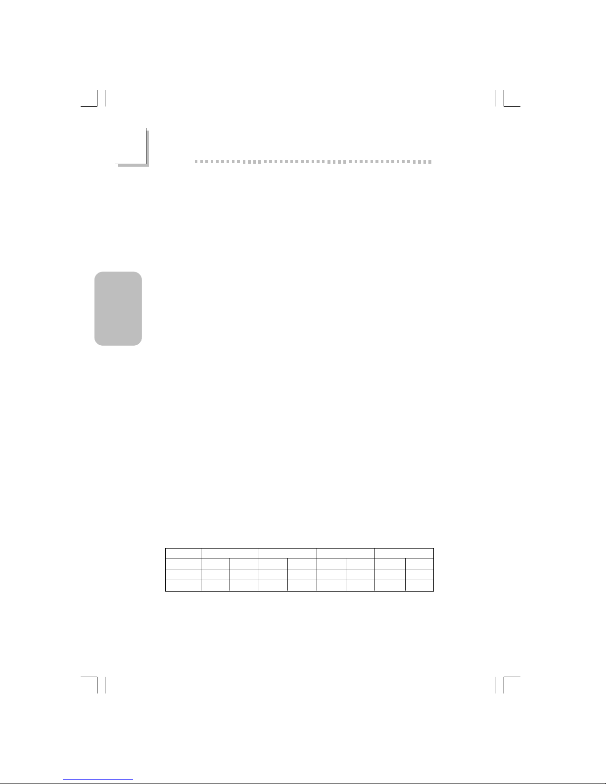
Density Width
Single/Double
184-pin DDR
64 Mbit
X8
SS/DS
64/128MB
X16
SS/DS
32MB/NA
Density
128 Mbit
X8
SS/DS
128/256MB
X16
SS/DS
64MB/NA
256 Mbit
X8
SS/DS
256/512MB
X16
SS/DS
128MB/NA
512 Mbit
X8
SS/DS
512/1024MB
X16
SS/DS
256MB/NA
Page 37

37
2
English
English
Expansion Slots
The system board is equipped with 1 AGP/ADD slot and 6 PCI
slots.
The AGP slot only supports 1.5V AGP 4x (1066MB/sec. bandwidth)
add-in cards. AGP is an interface designed to support high
performance 3D graphics cards for 3D graphics applications. It
handles large amounts of graphics data with the following features:
• Pipelined memor y read and write operations that hide memor y
access latency.
• Demultiplexing of address and data on the bus for nearly 100
percent efficiency.
The ADD slot is used for installing an ADD (AGP Digital Display)
card.
Onboard Graphics Features
• Graphics memory
- Shares 512K/1MB/8MB of the system memory in DOS
mode
- Uses Dynamic Video Memory Technology (DVMT) in
Windows mode
• Graphics controller
- Core frequency of 200MHz
- 350MHz integrated 24-bit RAMDAC
- Analog display up to 2048x1536 @ 60Hz refresh
- 3D setup and render engine - Discrete , Triangles, Str ips and
fans
- Per pixel perspective corrected texture mapping
- Software DVD at 30fps, full screen
• 2D graphics features
- Optimized 256-bit BLT engine
- 32-bit alpha blended cursor
- Programmable 3-color tr ansparent cur sor
• 3D graphics features
- 200 megapixels/sec fill rate
- Maximum 3D resolution: 1600x1200x32 @ 85Hz
- Flat and Gouraud shading
- 16- and 24-bit Z-buffering and 16- and 24-bit W-buffering
- Vertex and programmable pixel fogging and
atmospheric effects
Page 38

38
English
2
English
- Double and triple render buffer
• Software drivers
- Windows® 98SE/2000/ME/XP
- Windows NT® 4.0
Onboard Audio Features
• 18-bit stereo full-duplex codec with independent variable sampling rate
• High quality differential CD input
• True stereo line level outputs
• S/PDIF-out interface
• 2-channel audio output
Onboard LAN Features (NB76-BL only)
• Uses Realtek RTL8100 fast ethernet controller
• Integrated IEEE 802.3 10BASE-T and 100BASE-TX compatible
PHY
• 32-bit PCI master interface
• Integrated power management functions
• Full duplex suppor t at both 10 and 100 Mbps
• Suppor ts IEEE 802.3u auto-negotiation
• Suppor ts wire for management
Compatibility
• Microsoft PC ’98 compliant
• PCI 2.2 and AC ’97 compliant
• Intel AGP version 2.0
ATX Double Deck Ports (PC 99 color-coded connectors)
• 4 USB 2.0/1.1 ports
• 1 RJ45 LAN port (NB76-BL only)
• 1 NS16C550A-compatible DB-9 serial por t
• 1 DB-15 VGA por t
• 1 DB-25 parallel por t
• 1 mini-DIN-6 PS/2 mouse port
• 1 mini-DIN-6 PS/2 keyboard port
• 3 audio jacks: line-out, line-in and mic-in
Page 39

39
2
English
English
Connectors
• 1 connector for 2 additional external USB 2.0/1.1 por ts
• 1 connector for 1 external serial port
• 1 connector for an external game/MIDI port
• 2 internal audio connectors (CD-in and TAD)
• 1 S/PDIF-out connector
• 1 connector for IrDA interface
• 2 IDE connectors
• 1 floppy drive interface supports up to two 2.88MB floppy
drives
• 2 ATX power supply connectors
• 1 Wake-On-LAN connector
• 1 Wake-On-Ring connector
• CPU fan, chassis fan and second fan connectors
PCI Bus Master IDE Controller
• Two PCI IDE interfaces support up to four IDE devices
• Supports ATA/33, ATA/66 and ATA/100 hard drives
• PIO Mode 4 Enhanced IDE (data transfer rate up to 14MB/sec.)
• Bus mastering reduces CPU utilization during disk transfer
• Suppor ts ATAPI CD-ROM, LS-120 and ZIP
S/PDIF
The system board is equipped with the S/PDIF (Sony/Philips Digital
Interface) digital audio interface. S/PDIF is a standard audio file
transfer format that transfer s digital audio signals to a device without
having to be converted first to an analog for mat. This prevents the
quality of the audio signal from degrading whenever it is converted
to analog.
IrDA Interface
The system board is equipped with an IrDA connector for wireless
connectivity between your computer and peripheral devices.
Page 40

40
English
2
English
USB Ports
The system board supports USB 2.0 and USB 1.1 ports. USB 1.1
suppor ts 12Mb/second bandwidth while USB 2.0 supports 480Mb/
second bandwidth providing a marked improvement in device
transfer speeds between your computer and a wide range of
simultaneously accessible external Plug and Play peripherals.
BIOS
• Award BIOS, Windows® 98SE/2000/ME/XP Plug and Play compatible
• Suppor ts SCSI sequential boot-up
• Flash EPROM for easy BIOS upgrades
• Supports DMI 2.0 function
Desktop Management Interface (DMI)
The system board comes with a DMI 2.0 built into the BIOS. The
DMI utility in the BIOS automatically records various information
about your system configuration and stores these information in the
DMI pool, which is a part of the system board's Plug and Play
BIOS. DMI, along with the appropriately networked software, is
designed to make inventory, maintenance and troubleshooting of
computer systems easier.
2.1.2 Intelligence
Dual Function Power Button
Depending on the setting in the “Soft-Off By PWR-BTTN” field of
the Power Management Setup, this switch will allow the system to
enter the Soft-Off or Suspend mode.
Wake-On-Ring
This feature allows the system that is in the Suspend mode or Soft
Power Off mode to wake-up/power-on to respond to calls coming
through an internal or external modem.
Important:
If you are using a modem add-in card, the 5VSB power source
of your power supply must support ≥720mA.
Page 41

41
2
English
English
Wake-On-LAN
The Wake-On-LAN function is applicable only when you are using a
LAN add-in card that has the same function. It allows the network
to remotely wake up a Soft Power Down (Soft-Off) PC. Your LAN
card must support the remote wak eup function.
Important:
The 5VSB power source of your power supply must support
≥
720mA.
Wake-On-Keyboard/Wake-On-Mouse
This function allows you to use the keyboard or PS/2 mouse to
power-on the system.
Important:
• The power button will not function once a keyboard
password has been set in the “KB Power On Password”
field of the Integrated Peripherals submenu. You must type
the correct password to power-on the system. If you forgot
the password, power-off the system and remove the
battery. Wait for a few seconds and install it back before
powering-on the system.
• The 5VSB power source of your power supply must
support ≥720mA.
Wake-On-USB Keyboard
The Wake-On-USB Keyboard function allows you to use a USB
keyboard to wake up a system that is in the S3 (STR - Suspend To
RAM) state.
Important:
• If you are using the Wake-On-USB Keyboard function for 2
USB ports, the 5VSB power source of your power supply
must support ≥1.5A.
• If you are using the Wake-On-USB Keyboard function for
≥
4 USB ports, the 5VSB power source of your power
supply must support ≥2A.
Page 42

42
English
2
English
RTC Timer to Power-on the System
The RTC installed on the system board allows your system to
automatically power-on on the set date and time .
ACPI STR
The system board is designed to meet the ACPI (Advanced
Configuration and Power Interface) specification. ACPI has energy
saving features that enables PCs to implement Power Management
and Plug-and-Play with operating systems that support OS Direct
Power Management. Currently, only Windows
®®
®®
®
98SE/2000/ME/XP
supports the ACPI function. ACPI when enabled in the Power
Management Setup will allow you to use the Suspend to RAM
function.
With the Suspend to RAM function enabled, you can power-off the
system at once by pressing the power button or selecting “Standby”
when you shut down Windows
®®
®®
®
98SE/2000/ME/XP without having
to go through the sometimes tiresome process of closing files,
applications and operating system. This is because the system is
capable of storing all programs and data files during the entire
operating session into RAM (Random Access Memory) when it
powers-off. The operating session will resume exactly where you left
off the next time you power-on the system.
Important:
The 5VSB power source of your power supply must support
≥
1A.
AC Power Failure Recovery
When power returns after an AC power failure, you may choose to
either power-on the system manually, let the system power-on
automatically or return to the state where you left off before power
failure occurs.
Virus Protection
Most viruses today destroy data stored in hard drives. The system
board is designed to protect the boot sector and par tition table of
your hard disk drive.
Page 43

43
2
English
English
2.2 Supported Softwares
2.2.1 Intel Chipset Software Installation Utility
The Intel Chipset Software Installation Utility is used for updating
Windows 98SE/2000/ME/XP's INF files so that the Intel chipset
can be recognized and configured properly in the system.
To install the utility, please follow the steps below.
1. Click “Intel Chipset Software Installation Utility”.
2. Follow the prompts on the screen to complete installation.
3. Reboot the system for the utility to take effect.
2.2.2 Intel 845G/GL Graphics Drivers
To install the driver, please follow the steps below.
1. Click “Intel 845G/GL Gr aphics Driver s”.
2. Follow the prompts on the screen to complete installation.
3. Reboot the system for the driver to take effect.
2.2.3 Realtek AC’97 Audio Drivers
The audio drivers are suppor ted in the following operating systems:
Windows 98 SE, Windows ME, Windo ws NT 4.0, Windows 2000
and Windows XP.
To install the driver, please follow the steps below.
1. Click “Realtek AC’97 Audio Drivers”.
2. Follow the prompts on the screen to complete installation.
3. Reboot the system for the driver to take effect.
2.2.4 USB 2.0 Drivers
If you are using a USB 2.0 device, you must install the USB 2.0
driver. The driver s are suppor ted in the following operating systems:
Windows 98 SE, Windows ME, Windo ws 2000 and Windows XP.
Page 44

44
English
2
English
To install the driver, please follow the steps below.
1. Click “USB 2.0 Dr iver s”.
2. Follow the installation instructions shown on the screen.
3. Reboot the system for the driver to take effect.
2.2.5 Realtek LAN Drivers (NB76-BL only)
The LAN drivers support autorun for the following operating
systems: Windows 98 SE, Windows ME, Windows 2000 and
Windows XP.
To install the driver, please follow the steps below.
1. Click “Realtek LAN Drivers”.
2. Follow the prompts on the screen to complete installation.
3. Reboot the system for the driver to take effect.
The LAN driver for Windows NT 4.0 does not suppor t “Autorun”.
Once the Windows NT 4.0 system has detected the Realtek
RTL8100 fast ethernet controller, it will prompt you to install the
driver. The driver is in the “LAN\WINNT4” directory of the CD.
2.2.6 Intel Application Accelerator
The Intel Application Accelerator is designed to improve
performance of the storage subsystem and overall system
performance. It delivers improved performance through several
ingredient technologies (components).
To install, please follow the steps below.
1. Click “Intel Application Accelerator”.
2. Follow the prompts on the screen to complete installation.
3. Reboot the system for the driver to take effect.
Page 45

45
2
English
English
2.2.7 Microsoft DirectX 8.1 Driver
To install, please follow the steps below.
1. Click “Microsoft DirectX 8.1”.
2. Click “Yes” to continue.
3. Follow the prompts on the screen to complete installation.
4. Reboot the system for the driver to take effect.
2.2.8 McAfee VirusScan Online
The McAfee VirusScan Online is the most reliable and convenient
way of protecting your PC from computer viruses. When you install
McAfee VirusScan Online, your computer is safe because it
automatically scans for viruses and checks for vir us updates so that
PC protection stays up-to-date.
To install, please follow the steps below.
1. On the autorun screen, click “More.”.
2. Click “McAfee VirusScan Online”.
3. Click “Yes” to continue .
4. Follow the prompts on the screen to complete installation.
5. Restar t the system.
2.2.9 Installation Notes
1. "Autorun" ONLY suppor ts the Windows 98 SE, Windows ME,
Windows 2000, Windows NT 4.0 and Windows XP
operating systems. If after inserting the CD, "Autorun" did not
automatically star t (which is, the Main Board Utility CD screen
did not appear), please go directly to the root director y of the
CD and double-click "Select".
2. All steps or procedures to install software drivers are subject to
change without notice as the softwares are occassionally updated.
Please go to DFI's web site at "http://www.dfi.com/support1/
download2.asp" for the latest version of the dr ivers or software
applications.
Page 46

46
English
2
English
2.3 Troubleshooting
This section of the manual is designed to help you with problems
that you may encounter with your personal computer. To efficiently
troubleshoot your system, treat each problem individually. This is to
ensure an accurate diagnosis of the problem in case a problem has
multiple causes.
Some of the most common things to check when you encounter
problems while using your system are listed below.
1. The power switch of each peripheral device is turned on.
2. All cables and power cords are tightly connected.
3. The electrical outlet to which your peripheral devices are
connected is working. Test the outlet by plugging in a lamp or
other electrical device.
4. The monitor is turned on.
5. The display’s brightness and contrast controls are adjusted
properly.
6. All add-in boards in the expansion slots are seated securely.
7. Any add-in board you have installed is designed for your system
and is set up correctly.
Monitor/Display
If the display screen remains dark after the system is turned on:
1. Make sure that the monitor’s power switch is on.
2. Check that one end of the monitor’s power cord is properly
attached to the monitor and the other end is plugged into a
working AC outlet. If necessary, tr y another outlet.
3. Check that the video input cable is properly attached to the
monitor and the system’s display adapter.
4. Adjust the brightness of the display by turning the monitor’s
brightness control knob.
Page 47

47
2
English
English
The picture seems to be constantly moving.
1. The monitor has lost its vertical sync . Adjust the monitor’s ver tical
sync.
2. Move away any objects, such as another monitor or fan, that
may be creating a magnetic field around the display.
3. Make sure your video card’s output frequencies are supported
by this monitor.
The screen seems to be constantly wavering.
1. If the monitor is close to another monitor, the adjacent monitor
may need to be turned off. Fluorescent lights adjacent to the
monitor may also cause screen wavering.
Power Supply
When the computer is turned on, nothing happens.
1. Check that one end of the AC power cord is plugged into a live
outlet and the other end properly plugged into the back of the
system.
2. Make sure that the voltage selection switch on the back panel is
set for the correct type of voltage you are using.
3. The power cord may have a “shor t” or “open”. Inspect the cord
and install a new one if necessar y.
Floppy Drive
The computer cannot access the floppy drive.
1. The floppy diskette may not be formatted. Format the diskette
and tr y again.
2. The diskette may be write-protected. Use a diskette that is not
write-protected.
3. You may be writing to the wrong drive. Check the path
statement to make sure you are writing to the targeted drive.
4. There is not enough space left on the diskette. Use another
diskette with adequate storage space.
Page 48

48
English
2
English
Hard Drive
Hard disk failure.
1. Make sure the correct drive type for the hard disk drive has
been entered in the BIOS.
2. If the system is configured with two hard drives, make sure the
bootable (first) hard drive is configured as Master and the
second hard drive is configured as Slave. The master hard drive
must have an active/bootable par tition.
Excessively long formatting period.
1. If your hard drive takes an excessively long period of time to
format, it is likely a cable connection problem. However, if your
hard drive has a large capacity, it will take a longer time to
format.
Parallel Port
The parallel printer doesn’t respond when you try to print.
1. Make sure that your printer is turned on and that the printer is
on-line.
2. Make sure your software is configured for the right type of
printer attached.
3. Verify that the onboard LPT port’s I/O address and IRQ settings
are configured correctly.
4. Verify that the attached device works by attaching it to a parallel
port that is working and configured correctly. If it works, the
printer can be assumed to be in good condition. If the printer
remains inoperative, replace the printer cable and try again.
Serial Port
The serial device (modem, printer) doesn’t output anything or is
outputting garbled characters.
1. Make sure that the serial device’s power is turned on and that
the device is on-line.
2. Verify that the device is plugged into the correct serial por t on
the rear of the computer.
Page 49

49
2
English
English
3. Verify that the attached serial device works by attaching it to a
serial por t that is working and configured correctly. If the serial
device does not work, either the cable or the serial device has a
problem. If the ser ial device works, the problem may be due to
the onboard I/O or the address setting.
4. Make sure the COM settings and I/O address are configured
correctly .
Keyboard
Nothing happens when a key on the keyboard was pressed.
1. Make sure the keyboard is properly connected.
2. Make sure there are no objects resting on the keyboard and
that no keys are pressed during the booting process.
System Board
1. Make sure the add-in card is seated securely in the expansion
slot. If the add-in card is loose, power off the system, re-install
the card and power up the system.
2. Check the jumper settings to ensure that the jumpers are
properly set.
3. Verify that all memory modules are seated securely into the
memory sock ets.
4. Make sure the memory modules are in the cor rect locations.
5. If the board fails to function, place the board on a flat surface
and seat all socketed components. Gently press each component
into the socket.
6. If you made changes to the BIOS settings, re-enter setup and
load the BIOS defaults.
Page 50

50
3
Français
(French)
Français (French)
Français
Chapter 3 - Français (French)
Table des Matières
Liste de Vérification de l’Emballage
L’emballage de la car te système contient les éléments suivants:
! 1 carte système
! 1 manuel utilisateur
! 1 carte montée par attache sur le côté avec 1 port série et 1 port
jeux/MIDI supporte une vitesse de
" 1 support pour cartes montée avec 1 connecteurs sortie - S/PDIF
(optionnel)
! 1 câble IDE pour les lecteurs IDE ATA/33, ATA/66 ou
ATA/100
! 1 câble 34 broches pour lecteur de disquette
! 1 CD “Main Board Utility”
Si l’un de ces éléments n’était pas dans l’emballage ou s’il était
endommagé, veuillez contacter votre revendeur ou votre
représentant.
3.1 Caractéristiques et Spécifications......................................................................
3. 2 Logiciels Supportés........................................................................................................
3.3 Dépannage............................................................................................................................
51
59
63
Note:
Le manuel d’utilisateur dans le CD muni contient renseignement
détaillé au sujet de carte de système. Si, en quelque cas, quelque
renseignement n’appareille de ce que dit dans ce manuel, ce manuel
doit toujours être considéré comme la plus nouvelle version.
Page 51
51
3
Français
(French)
Français (French)
3.1 Caractéristiques et Spécifications
3.1.1 Caractéristiques
Chipset
• Intel® 845G chipset
- Intel® 845G Graphiques Controlleur du Mémoire (GMCH -
Memor y Controller Hub)
- Intel® 82801DB I/O Controleur Entrée/Sorr tie (ICH4 - I/O
Controller Hub)
Processeur
La carte est pourvue d’un Socket 478 permettant d’exploiter un
processeur Pentium® 4 ou processeur Celeron
®
• Processeur Intel® Pentium® 4 (478 broches)
- 533MHz vitesse du bus - suppor te up to 2.53 GHz CPU
speed
- 400MHz vitesse du bus - supporte up to 2.4 GHz CPU
speed
• Processeur Intel® Celeron® 4 (478 broches)
- 400MHz vitesse du bus - supporte up to 1.7 GHz CPU
speed
Mémoire Système
• 2 sockets PC DDR SDRAM DIMM 184 broches
• Supporte DDR SDRAM DIMM 2.5V PC1600 (DDR200) /
PC2100 (DDR266)
• Permettre l’utilisation de maximum de 2GB système mémoire
utilisant technologie de 64Mbit, 128Mbit, 256Mbit ou 512Mbit
- Ne permettre pas l’utilisation de x16 DDR SDRAM DIMM à
deux faces
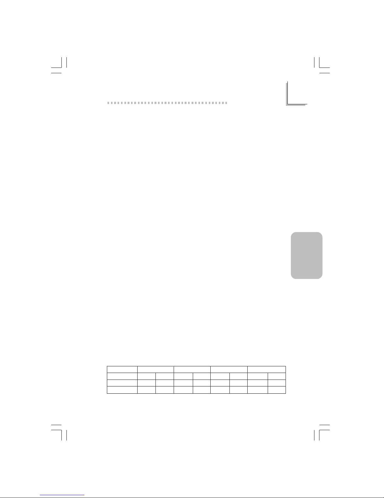
Largeur de Densité
Simple/Double
184-pin DDR
64 Mbit
X8
SS/DS
64/128MB
X16
SS/DS
32MB/NA
Densité
128 Mbit
X8
SS/DS
128/256MB
X16
SS/DS
64MB/NA
256 Mbit
X8
SS/DS
256/512MB
X16
SS/DS
128MB/NA
512 Mbit
X8
SS/DS
512/1024MB
X16
SS/DS
256MB/NA
Page 52

52
3
Français
(French)
Français (French)
Français
Logements d’Extension
La carte système est équipée d’un slot 1 AGP/ ADD , en 6 slots PCI
Le slot AGP supporte seulement les cartes AGP 4x 1.5V (une
Bande passante de 1066MB/sec.). AGP est une interface constr uite
pour supporter les cartes graphiques de haute performance 3D
pour les applications graphiques 3D. Elle peut gérer une grande
quandité de données graphiques avec les par ticulatrités suivantes:
• Opération écriture/lecture du mémoire en tube (pipelined
memory) permet de diminuer la latence lors de l’accés au
mémoire video.
• Démultiplxe d’adresses et de donnés dans le bus pour une
efficacité proche de 100%.
Le slot ADD est utilisé pour installer une car te ADD (AGP Digital
Display – Aff ichage Digitale A GP).
Fonctions de la carte graphique intégrée
• Mémoires Graphiques
- Partagent avec le systeème 512K/1MB/8MB, sous le DOS
- Utilisent la technologie de la mémoire Vidéo Dynamique
(Dynamic Video Memory T echnology - DVMT) sous Windows
• Contrôleur Graphique
- Fréquence interne à 200MHz
- RAMDAC 24-bits intégré à 350MHz
- Afficahge analogue pouvant monter jusqu’à 2048x1536 @
60Hz rafraichissement
- moteur pour le rendu et setup 3D - Discrète, Triangles,
Rayures et évantails
- Correction perspective du mapping textuelle au niveau du
pixel
- Décodage DVD par software à 30fps, en plein écr an
• fonctions graphiques 2D
- Moteur BLT 256-bits optimisé
- 32-bit alpha blended cursor
- curseur transparent 3-couleur s progr ammable
Page 53

53
3
Français
(French)
Français (French)
• fonctions graphiques 3D
- taux de remplissage à 200 megapixels/sec
- Résolution 3D maximum: 1600x1200x32 @ 85Hz
- Ombrage plat et gouraud
- Z-buffering 16- et 24-bit et W-buffering 16- et 24-bit
- Vertex et pixel programmable effet brouillard et
atmosphérique
- Double et triple tampons pour la rendue
• Conducteur de logiciel
- Windows® 98SE/2000/ME/XP
- Windows NT® 4.0
Caractéristiques Audio sur Carte
• Codec full-duplex 18 bits stéréo avec fréquence d’échantillonnage
variable indépendante
• Entrée CD différentielle de haute qualité
• Sor ties de niveau de lignes stéréo vraies
• Interface sor tie S/PDIF
• Sortie audio 2-canaux
Fonctionnalités Onboard LAN (NB76-BL seulement)
• Utilise le contrôleur Realtek RTL8100 Fast Ethernet
• IEEE 802.3, 10BASE-T et 100BASE-TX intégrés compatibles PHY
• Interface maître PCI 32 bits
• Fonctions de gestion d’alimentation intégrées
• Suppor t Full duplex à 10 et 100 Mbps
• Suppor te l’auto négociation IEEE 802.3u
• Suppor t câble pour la gestion
Compatibilité
• Compatible Microsoft® PC ’98
• Compatible PCI 2.2 et AC’97
• Intel AGP version 2.0
Ports Double Module ATX (Connecteurs PC 99 avec codes
couleur)
• 4 por ts USB 2.0/1.1
• 1 por t RJ45 LAN (NB76-BL seulement)
Page 54

54
3
Français
(French)
Français (French)
Français
• 1 por ts série DB-9 compatible NS16C550A
• 1 port de DB-15 VGA
• 1 por t par allèle DB-25
• 1 por t souris PS/2 mini-DIN-6
• 1 por t clavier PS/2 mini-DIN-6
• 3 prises audio: ligne de sortie (line-out), ligne d’entrée (line-in) et
entrée micro (mic-in)
Connecteurs
• 1 connecteur pour 2 por ts USB2.0/1.1 supplémentaires
• 1 connecteur pour 1 pour de série externe
• 1 connecteur pour 1 pour de jeu/MIDI externe
• 2 connecteurs audio internes - CD-in, AUX-in, Video-in et TAD
• 1 connecteur sortie S/PDIF
• 1 connecteur pour interface IrDA
• 2 connecteurs IDE
• 1 connecteur de lecteur de disquettes suppor tant jusqu’à deux
lecteurs de disquettes de 2.88Mo
• 2 connecteurs d’alimentation ATX
• 1 connecteur Wake-On-LAN
• 1 connecteur Wake-On-Ring
• Connecteurs de ventilateurs de CPU, de châssis et de second
ventilateur
Contrôleur IDE de BUS Maître PCI
• Deux interfaces PCI IDE suppor tant jusqu’à quatre matériels IDE
• Suppor te des disques durs ATA/33, ATA/66 et ATA/100
• IDE Améliorés Mode 4 PIO (vitesse de transfert de données
allant jusqu’à 14Mo/sec.)
• La gestion de Bus réduit l’utilisation du CPU pendant les
transfer ts sur disque
• Suppor te les CD-ROM ATAPI, LS-120 et ZIP
Page 55

55
3
Français
(French)
Français (French)
S/PDIF
La carte système est équipée d’une interface audio digitale S/PDIF
(Sony/Philips Digital Interface). La S/PDIF est un format standardisé
pour le transfert des fichiers audio permettant de transférer des
signaux audio digitaux à un appareil périphérique sans la conversion
en signaux analogues préalable. Ceci permet de conserver la qualité
du signal audio en évitant la dégradation dûe à une conversion en
analogue.
Interface IrDA
La carte système est équipée d’un connecteur IrDA pour les
connexions sans fil entre votre ordinateur et des périphériques. Il
suppor te les périphériques qui sont conformes aux standards IrDA
ou ASKIR.
Ports USB
La carte mère supporte les quatre ports USB2.0 ou 1.1 permet
des échanges de données entre votre ordinateur et une multitude
de périphér iques “Plug and Play” accessibles simultanément.
BIOS
• Compatible avec Award BIOS, Windows® 98SE/2000/ME/XP
Plug and Play
• Suppor te l’amorçage séquentiel SCSI
• EPROM Flash pour une mise à niveau facile du BIOS
• Suppor te la fonction DMI 2.0
Interface de Gestion de Bureau (DMI)
La carte système est livrée avec un DMI 2.0 intégré au BIOS.
L’utilitaire DMI dans le BIOS enregistre automatiquement diverses
informations concernant la configuration de votre système et stocke
ces informations dans la liste DMI, qui est une partie du BIOS “Plug
and Play” de la carte système. DMI, accompagné du logiciel en
réseau approprié, est conçu pour rendre l’inventaire, l’entretien et le
dépannage du système de l’ordinateur plus facile.
Page 56

56
3
Français
(French)
Français (French)
Français
3.1.2 Intelligence
Bouton d’Alimentation à Fonction Double
En fonction du paramétrage dans le champ “Soft-Off By PWRBTTN” du Programme d’Installation de la Power Management Setup,
ce commutateur permettra à votre système d’entrer en mode SoftOff ou Suspension.
Eveil Sonnerie (Wake-On-Ring)
Cette caractéristique permet au système qui se trouve en mode
Suspension ou en mode Arrêt Alimentation par Logiciel de se
réveiller/s’allumer pour répondre à des appels provenant d’un
modem interne ou externe.
Important:
Si vous utilisez une carte complémentaire de modem, la source
d’alimentation de 5VSB de votre boîtier d’alimentation doit
supporter ≥720mA.
Eveil LAN (Wake-On-LAN)
La fonction Eveil LAN permet au réseau de réveiller à distance un
PC Mis Hors Tension par Logiciel (Soft Power Down ou Soft- Off)
provenant d’un votre carte LAN. Votre carte LAN doit supporter la
fonction de réveil à distance.
Important:
La source d’alimentation 5VSB de votre boîtier d’alimentation
doit supporter ≥720mA.
Page 57

57
3
Français
(French)
Français (French)
Réveil-Sur-Clavier/Réveil-Sur-Souris (Wake-On-Keyboard/WakeOn-Mouse)
Cette fonction vous permet d’utiliser le clavier ou la PS/2 souris pour
allumer le système.
Important:
• Le bouton d’alimentation ne fonctionnera plus une fois que
le mot de passe de clavier aura été paramétré dans le
champ “KB Power On Password” du sous menu de
Integrated Peripherals. Vous devez taper le mot de passe
correct pour allumer le système. Si vous avez oublié le mot
de passe, éteignez le système et retirez la batterie.
Attendez quelques secondes et réinstallez-la avant de
rallumer le système.
• La source d’alimentation 5VSB de votre boîtier d’alimentation
doit supporter ≥720mA.
Eveil Clavier USB (Wake-On-USB Keyboard)
La fonction Eveil Clavier USB vous permet d’utiliser un clavier USB
pour éveiller un système se trouvant en état S3 (STR-Suspension Sur
RAM).
Important:
• Si vous utilisez les fonctions Eveil Clavier USB (Wake-On-USB
Keyboard) pour 2 ports USB, la source d’alimentation 5VSB
de votre bloc d’alimentation doit supporter ≥1.5A.
• Si vous utilisez les fonctions Eveil Clavier USB (Wake-On-USB
Keyboard) pour ≥4 ports USB, la source d’alimentation 5VSB
de votre bloc d’alimentation doit supporter ≥2A.
Minuterie RTC pour Allumer le Système
Le RTC installé sur la carte système permet à votre système de
s’allumer automatiquement à une date et heure présélectionnée.
ACPI STR
La carte système est conçue de façon à être conforme aux
spécifications ACPI (Configuration Avancée et Interface
Page 58

58
3
Français
(French)
Français (French)
Français
d’Alimentation). ACPI compor te une fonction d’économie d’énergie
qui permet aux PC de mettre en œuvre la Gestion d’Alimentation
et “Plug and Play” avec des systèmes d’exploitation qui suppor tent
la Gestion d’Alimentation Directe de Système d’Exploitation.
Actuellement, seulement Windows® 98SE/2000/ME/XP supporte la
fonction ACPI. Quand ACPI est activé dans le Programme de Power
Management Setup, cela vous permet d’utiliser la fonction de
Suspension sur RAM.
Quand la fonction de Suspension sur RAM est activée, vous pouvez
éteindre le système immédiatement en appuyant sur le bouton
d’alimentation ou en sélectionnant “Veille” quand vous éteignez
Windows® 98SE/2000/ME/XP sans avoir à passer par le processus
quelquefois ennuyeux de fermeture des fichier s, des applications et
du système d’exploitation. Ceci est du au fait que le système est
capable de stocker tous les fichiers programmes et de données
pendant toute la session d’utilisation dans la RAM (Mémoire à Accès
Aléatoire) lorsque qu’il s’éteint. La session d’utilisation reprendra
exactement où vous l’avez laissée la prochaine fois que vous
allumerez le système.
Important:
La source d’alimentation 5VSB de votre boîtier d’alimentation
doit supporter ≥1A.
Récupération après Défaillance d’Alimentation CA
Quand l’alimentation revient après une défaillance d’alimentation CA,
vous pouvez choisir d’allumer le système manuellement, de laisser le
système s’allumer automatiquement ou de retourner à l’état que
vous aviez quitté avant que la défaillance d’alimentation se produise.
Protection Contre les Virus
La plupar t des vir us détruisent les données stockées sur les disques
durs. La carte système est conçue pour protéger le secteur
d’amorçage et la table de par tition de votre disque dur.
Page 59

59
3
Français
(French)
Français (French)
3.2 Logiciels Supportés
3.2.1 L’utilitaire d’installation pour le Chipset Intel
L ’utilitaire d’installation pour le Chipset Intel est utilisé pour mettre à jour
les fichiers INF de Windo ws® 98SE/2000/ME/XP. Ceci permet au système
de reconnaitre correctement la présence du chipset Intel et sa
configuration correcte.
Pour installer le programme, veuillez suivre les étapes suivantes.
1. Cliquer sur “Intel Chipset Software Installation Utility”.
2. Suivez les instrucions apparaissent sur l’écr an pour continuer
l’installation.
3. Redémarrer le system àfin que l’installation soit complète.
3.2.2 Les pilotes Graphiques d’Intel 845G/GL
Pour installer le programme, veuillez suivre les étapes suivantes.
1. Cliquer sur “Intel 845G/GL Gr aphics Drive rs”.
2. Suivez les instrucions apparaissent sur l’écr an pour continuer
l’installation.
3. Redémarrer le system àfin que l’installation soit complète.
3.2.3 Drivers de Realtek AC’97 Audio
Le drivers de Realtek AC’97 Audio suppor té de la carte système
comprend aussi des drivers audio pour Windows 98 SE, Windows
ME, Windo ws NT 4.0, Windows 2000 and Windows XP.
Pour installer le programme, veuillez suivre les étapes suivantes.
1. Cliquer sur “Realtek AC’97 Audio Driver s”.
2. Suivez les instrucions apparaissent sur l’écr an pour continuer
l’installation.
3. Redémarrer le system àfin que l’installation soit complète.
Page 60

60
3
Français
(French)
Français (French)
Français
3.2.4 Pilote USB 2.0
Installer le pilote USB 2.0 de Microsoft. Ce pilote supporte
uniquement les systèmes Windows 98 SE, Windows ME, Windo ws
2000 and Windows XP.
Pour installer le programme, veuillez suivre les étapes suivantes.
1. Cliquer sur “USB 2.0 Drivers”.
2. Suivez les instrucions apparaissent sur l’écran pour continuer
l’installation.
3. Redémarrer le system àfin que l’installation soit complète.
3.2.5 Les Pilotes Realtek LAN (NB76-BL seulement)
Les pilotes Realtek LAN supportent pas “Autorun” supporte
uniquement les systèmes Windows 98 SE, Windows ME,
Windows 2000 and Windows XP.
Pour installer le programme, veuillez suivre les étapes suivantes.
1. Cliquer sur “Realtek LAN Drivers”.
2. Suivez les instrucions apparaissent sur l’écran pour continuer
l’installation.
3. Redémarrer le system àfin que l’installation soit complète.
L’installation du pilote du reseau pour Windows NT® 4.0 ne se lance
pas automatiquement. Une foie que votre système ait détecté la
présence de la car te contrôlleur Fast Ethernet de Realtek RTL8100,
apparaitra une fenêtre du dialogue vous invitant à installer les pilotes
correspondants. Les pilotes sont dans le répertoire “LAN\WINNT4”
dans le CD.
3.2.6 Accélérateur d’Applications d’Intel
L’Accélérateur d’Applications d’Intel pour Windows (The Intel
®
Application Accelerator) est conçu pour améliorer la performance du
système du stockage mais aussi du système globalement parlant. La
réalisation est possible grâce à de nombreux ingrédients technologiques
(composants).
Page 61

61
3
Français
(French)
Français (French)
Pour installer le programme, veuillez suivre les étapes suivantes.
1. Cliquer sur “Intel Application Accelerator”.
2. Suivez les instrucions apparaissent sur l’écran pour continuer
l’installation.
3. Redémarrer le system àfin que l’installation soit complète.
3.2.7 Pilote de Microsoft DirectX 8.1
Pour installer le programme, veuillez suivre les étapes suivantes.
1. Cliquez sur “Microsoft DirectX 8.1”.
2. Cliquez sur “Yes” afin d’en continuer.
3. Suivez les instructions affichées sur le texte de boîte de dialogue
afin de compléter l’installation.
4. Redémarrez votre système.
3.2.8 McAfee VirusScan En Ligne
Le VirusScan En Ligne de McAfee est la méthode la plus sér ieuse et
simple d’utilisation pour protéger votre ordinateur contre les virus
informatiques. Après avoir installé le VirusScan En Ligne de McAfee,
votre machine restera en sécurité parce que le VirusScan En Ligne
recherche automatiquement les virus pour vous et actualise luimême la liste des des virus détectables pour que la protection de
votre PC soit toujour optimale.
Pour installer le programme, veuillez suivre les étapes suivantes.
1. Cliquez “More”.
2. Cliquez sur “McAfee VirusScan Online”.
3. Cliquez sur “Yes” afin d’en continuer.
4. Suivez les instructions affichées sur le texte de boîte de dialogue
afin de compléter l’installation.
5. Redémarrez votre système.
Page 62

62
3
Français
(French)
Français (French)
Français
3.2.9 Notes pour l’Installation des Pilotes et des Utilitaires
1. “Autorun” SEULEMENT supporte les systèmes d’exploitation
Windows® 98 SE, Windo ws® ME, Windows® 2000, Windows® XP
et WindowsNT
®
4.0. Si, après avoir inséré le CD, “Autor un” ne
démarre pas automatiquement (Dans ce cas, l’écran de CD Main
Board Utility n’apparaîtra pas), veuillez aller directement au
répertoire r acine du CD et double cliquez sur “Setup”.
2. Veuillez vous rendre sur le site web de DFI à "http://
www.dfi.com/support1/download2.asp" pour trouver la dernière
version des pilotes ou logiciel d’applications.
3. Toutes les étapes ou procédures pour installer les pilotes sont
susceptibles d’être modifiées sans notice préalable étant donné
que les logiciels sont mis à jour occasionnellement. Veuillez vous
repor ter aux fichiers LisezMoi, s’ils sont disponibles, pour obtenir
les dernières informations.
Page 63

63
3
Français
(French)
Français (French)
3.3 Dépannage
Ce chapitre du manuel est destiné à vous aider résoudre les
problèmes éventuels que vous pourriez rencontrer avec votre
ordinateur. Pour dépanner efficacement votre système, traitez chaque
problème individuellement. Ceci permettra de faire un diagnostique
exact du problème dans le cas ou celui-ci aurait des causes multiples.
Certains des points les plus courants, à vérifier lorsque vous
rencontrez des problèmes lors de l’utilisation de votre système sont
énumérés ci-dessous.
1. L’interrupteur d’alimentation de chaque périphérique est sur la
position marche.
2. Tous les câbles et cordons d’alimentation sont bien connectés.
3. La prise secteur sur laquelle vos périphériques sont branchés
fonctionne correctement. Testez la prise en branchant une lampe
ou tout autre appareil électrique.
4. Le moniteur est allumé.
5. Les contrôles de luminosité et de contraste d’affichage sont
correctement réglés.
6. Toutes les cartes d’extension situées dans les logements
d’extension sont correctement enfichées.
7. Chaque carte d’extension installée est conçue pour votre
système et paramétrée correctement.
Moniteur/Affichage
Si l’écran d’affichage reste éteint après la mise sous tension du
système.
1. Assurez vous que le bouton d’alimentation est sur la position
marche.
2. Vérifiez que l’une des extrémités du cordon d’alimentation du
moniteur est correctement connectée au moniteur et que l’autre
extrémité est branchée à une prise de courant C A en état de
marche. Si nécessaire, essayez une autre prise.
3. Vérifiez que le câble d’entrée vidéo est correctement connecté au
moniteur et à l’adaptateur d’affichage du système.
4. Ajustez la luminosité de l’affichage en tournant le bouton de
contrôle de luminosité du moniteur.
Page 64

64
3
Français
(French)
Français (French)
Français
L’image bouge constamment.
1. Le moniteur a perdu sa synchronisation verticale. Ajustez la
synchronisation ver ticale du moniteur.
2. Eloignez tous les objets, tel qu’un autre moniteur ou un
ventilateur, qui pourrait créer un champ magnétique autour de
l’affichage.
3. Assurez vous que les fréquences de sortie de votre car te vidéo
sont suppor tées par ce moniteur.
L’écran ondule constamment.
1. Si le moniteur est proche d’un autre moniteur, il est peut-être
nécessaire d’éteindre ce dernier. Les lampes fluorescentes situées
à proximité du moniteur peuvent aussi faire onduler l’image à
l’écran.
Alimentation
A la mise sous tension de l’ordinateur rien ne se passe.
1. Vérifiez que l’une des extrémités du cordon d’alimentation CA
est branchée dans une prise de courant en état de marche et
que l’autre extrémité est correctement branchée au dos du
système.
2. Assurez vous que l’interrupteur de sélection de voltage situé sur
le panneau arrière est positionné pour le type correct de voltage
que vous utilisez.
3. Le cordon d’alimentation présente peut-être un “court circuit” ou
une “coupure”. Inspectez le cordon et installez-en un nouveau si
nécessaire.
Lecteur de Disquettes
L’ordinateur ne peut pas accéder au lecteur de disquettes.
1. La disquette n’est peut-être pas formatée. Formatez la disquette
et réessayez.
2. La disquette est peut-être protégée en écriture. Utilisez une
disquette qui n’est pas protégée en écriture.
3. Vous êtes peut-être en train d’écrire sur le mauvais lecteur.
Vérifiez le chemin d’accès pour vous assurer que vous écrivez
bien sur le lecteur visé.
Page 65

65
3
Français
(French)
Français (French)
4. L’espace est insuffisant sur la disquette. Utilisez une autre
disquette compor tant un espace de stockage adéquat.
Disque Dur
Défaillance du disque dur.
1. Assurez vous que le type correct de lecteur pour le disque dur a
été entré dans le BIOS.
2. Si le système est configuré avec deux disques durs, assurez vous
que le disque dur amorçable (premier) est configuré en Maître et
le second disque dur est configuré en Esclave. Le disque dur
maître doit avoir une partition active/amorçable.
Durée de formatage trop longue.
1. Si votre disque dur met trop de temps à se formater, cela
provient sûrement d’un problème de connexion de câble.
Cependant, si votre disque dur a une grande capacité, il mettra
plus de temps à se formater.
Port Parallèle
L’imprimante parallèle ne répond pas quand vous essayez
d’imprimer.
1. Assurez vous que votre imprimante est allumée et que
l’imprimante est en ligne.
2. Assurez vous que votre logiciel est configuré pour le type
d’imprimante connectée.
3. Vérifiez que l’adresse d’E/S et les paramètres IRQ du por t LPT
sur car te sont configurés correctement.
4. Vérifiez que le périphérique connecté fonctionne en le connectant
à un por t parallèle qui fonctionne et configuré correctement. S’il
fonctionne, l’imprimante peut être considérée comme étant en
bon état de marche. Si l’imprimante ne fonctionne toujours pas,
remplacez le câble d’imprimante et essayez à nouveau.
Page 66

66
3
Français
(French)
Français (French)
Français
Port Série
Le périphérique série (modem, imprimante) n’émet aucun
caractère ou émet des caractères incohérents.
1. Assurez vous que le périphérique série est allumé et qu’il est en
ligne.
2. Vérifiez que le périphérique est br anché sur le por t sér ie correct
au dos de l’ordinateur.
3. Vérifiez que le périphérique série connecté fonctionne, en le
branchant à un port série qui fonctionne et configuré
correctement. Si le périphérique série ne fonctionne pas, cela
signifie que le câble ou le périphérique série a un problème. Si le
périphérique fonctionne, le problème est peut-être dû à la carte
d’E/S ou au paramétrage d’adressage.
4. Assurez vous que les paramètres COM et d’adressage d’E/S
sont configurés correctement.
Clavier
Rien ne se passe quand une touche du clavier est enfoncée.
1. Assurez vous que le clavier est connecté correctement.
2. Assurez vous qu’aucun objet n’appuie sur le clavier et qu’aucune
touche n’est enfoncée pendant le processus d’amorçage.
Carte Système
1. Assurez vous que la car te d’extension est correctement placée
dans le logement d’extension. Si la car te d’extension a du jeu,
éteignez le système, réinstallez la carte et allumez le système .
2. Vérifiez les paramétrages de cavalier s pour vous assurer que les
cavaliers sont positionnés correctement.
3. Vérifiez que tous les modules mémoire sont correctement
installés dans les sockets mémoire.
4. Assurez vous que les modules mémoire se trouvent dans les
emplacements appropriés.
5. Si la carte ne fonctionne pas, placez la carte sur une surface
plane et vérifiez tous les composants sur socket. Appuyez
doucement sur chaque composant pour l’enfoncer dans le socket.
6. Si vous avez apporté des modifications aux paramètres du BIOS,
ré entrez dans le programme d’installation et chargez les
paramètres par défaut du BIOS.
Page 67

67
4
Deutsch
(German)
Deutsch (German)
Chapter 4 - Deutsch (German)
Inhaltsverzeichnis
Verpackungsliste
In der Verpackung der Systemplatine sind folgende Ar tikel enthalten:
! 1 Systemplatine
! 1 Benutzerhandbuch
! 1 Kartenseite montiert mit einem Seriellen Port und einem
Game/MIDI Port. Unterstützt eine CPU
" 1 Direktbracket mit 1 S/PDIF-Aus Steckverbindern montiert
(Auf Wunsch erhältlich)
! 1 IDE-Kabel für ATA/33-IDE-Laufwerke, ATA/66-IDE-Laufwerke
oder ATA/100-IDE-Laufwerke
! 1 Floppylaufwerkskabel mit 34poligen Anschlußstecker
! 1 CD mit “Main Board Utility”
Fehlt einer dieser Artikel oder weist einer dieser Artikel
Beschädigungen auf, wenden Sie sich an Ihren Händler oder Vertreter.
4.1 Leistungsmer kmale und Technische Daten...............................................
4. 2 Unter stützte Software.................................................................................................
4.3 Fehlersuche............................................................................................................................
68
76
80
Hinweis:
Das Benutzerhandbuch in der angebotenen CD enthält detaillierte
Informationen über die Hauptplatine. Wenn in manchen Fällen
manche Informationen nicht denjenigen Informationen dargestellt in
diesem Handbuch entsprechen, soll dieses Handbuch als die meist
aktualisierte Ausgabe gelten.
Page 68
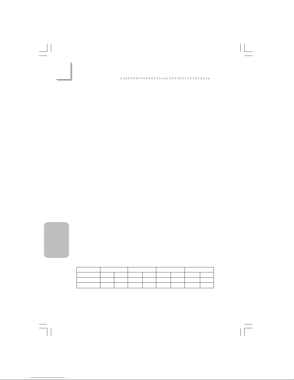
68
4
Deutsch
(German)
Deutsch (German)
Français
4.1 Leistungsmerkmale und Technische Daten
4.1.1 Leistungsmerkmale
Chipset
• Intel® 845G chipset
- Intel® 845G Graphikspeichersteuer ungs-Plattenmitte (GMCH)
- Intel® 82801DB I/O Steuerungsplattenmitte (ICH4)
Prozessor
Das Systemboard ist mit Socket 478 zur Installation eines Pentium
®
4-Prozessors ausgerüstet. und Prozessors Celeron
®
• Intel® Pentium® 4 Prozessor (478-polige)
- 533MHz Systemdatenbus - unterstützt up to 2.53 GHz CPU
speed
- 400MHz Systemdatenbus - unterstützt up to 2.4 GHz CPU
speed
• Intel® Celeron® Prozessor (478-polige)
- 400MHz Systemdatenbus - unterstützt up to 1.7 GHz CPU
speed
Systemspeicher
• Zwei 184-Stift DDR SDRAM DIMM Buchsen
• 2.5V ungepuffertes PC1600 (DDR200)/PC2100 (DDR266)
DDR SDRAM DIMM
• Maximalunterstützung von 2GB-Systemspeicher mittels
Verwendung von 64Megabit, 128Megabit, 256Megabit oder
512Megabit-Technologie
- Zweiseitig x16 DDR SDRAM DIMM wird nicht unterstützt
Dichtebreite
Einzel/Doppel
184-Stift DDR
64 Mbit
X8
SS/DS
64/128MB
X16
SS/DS
32MB/NA
Dichte
128 Mbit
X8
SS/DS
128/256MB
X16
SS/DS
64MB/NA
256 Mbit
X8
SS/DS
256/512MB
X16
SS/DS
128MB/NA
512 Mbit
X8
SS/DS
512/1024MB
X16
SS/DS
256MB/NA
Page 69

69
4
Deutsch
(German)
Deutsch (German)
Erweiterungssteckfasssungen
Die Hauptplatine ist mit 1 A GP/ADD-Einbauplatz, 6 PCI-Einbauplätz en
Der AGP Steckplatz unterstützt nur 1.5V AGP 4x- Zusatzkarten
(1066MB/Sek. Bandbreite). AGP ist ein Interface, welches
hochleistungsfähige 3D-Grafikkarten für 3D-Grafikanwendungen
unterstützt. Es verarbeitet große Mengen grafischer Daten mit den
folgenden Eigenschaften:
• Pipeline-Speicher-Lese- und Schreibbetrieb verbirgt
Speicherzugriffs-Latenz.
• Demultiplexing von Adressen und Daten auf dem Bus für fast
100-prozentige Effizienz.
Der ADD-Einbauplatz wird verwendet, um eine ADD (AGP Digital
Display)-Karte zu installieren.
Bordgraphikmerkmäle
• Graphikspeicher
- teilt 512K/1MB/8MB des Systemspeichers im DOS-Modus
- verwendet Dynamische Videospeicherungstechnologie (DVMT)
im Windows-Modus
• Graphikkontroller
- Kernfrequenz von 200MHz
- 350MHz mit 24-Bit RAMDAC integriert
- Analoge Anzeige bis zu 2048x1536 @ 60Hz Bildauffrischung
- 3D Einstellungs- und Bildaufbereitungsvorrichtung – Diskrete,
Dreiecke, Streifen und Fächer
- Pro Bildpunkt Bemusterung mit perspektivischer Anpassung
- Software-DVD bei 30BPS (Bildrahmen pro Sekunde),
Vollbildschirm
• 2D Graphikmerkmäle
- Optimierte 256-Bit BLT-Vorrichtung
- 32-Bit Cursor mit Alpha-Blending
- Programmierbarer 3-Farben Transparenter Cur sor
• 3D Graphikmerkmäle
- 200 Megabildpunkte/Sek Füllrate
- Maximale 3D Auflösung: 1600x1200x32 @ 85Hz
Page 70

70
4
Deutsch
(German)
Deutsch (German)
Français
- Flach- und Gouraud-Schattierung
- 16- and 24-Bit Z-Pufferbetrieb und 16- and 24-Bit WPufferbetrieb
- Eckpunkt- und programmierbares Bildpunktfogging und
atmosphärische Effekte
- Doppel- und Dreifach-Bildaufbereitungspuffer
• Software-Treiber
- Windows® 98SE/2000/ME/XP
- Windows NT® 4.0
Audiomerkmale auf Platine
• 18-Bit-Stereo-Vollduplex-Codec mit unabhängiger und variabler
Abtastfrequenz
• Hochwer tige CD-Differential-Eingabe
• Naturgetreue Stereo-Leitungspegel-Ausgabe
• S/PDIF-Aus-Schnittstelle
• 2-Kanal-Audioausgang
Merkmale des LANs auf Platine (NB76-BL nur für)
• Benutzung des Realtek RTL8100 für die Fast-Ethernet-Verbindung
• Integrier ter IEEE 802.3, 10BASE-T und 100BASE-TX kompatibler
PHY
• 32-Bit-PCI-Master-Schnittstelle
• Integrierte Power-Management-Funktionen
• Vollduplex-Unterstützung bei 10 und 100 Mbps
• Unterstützung der IEEE-802.3u-Auto-Negotiation
• Unterstützung des Leiter s für das Management
Kompatibilität
• Kompatibilität mit Microsoft® PC ’98
• Kompatibilität mit PCI 2.2 und AC’97
• Intel AGP, version 2.0
ATX-Zweietagen-Anschlüsse (PC 99 mit farbkodierten
Steckverbindungen)
• 4 USB2.0/1.1-Anschlüsse
• 1 RJ45 LAN por t (NB76-BL nur für)
• 1 serieller DB-9-Anschluß, kompatibel mit NS16C550A
Page 71

71
4
Deutsch
(German)
Deutsch (German)
• 1 DB-15 VGA Port
• 1 DB-25-Parallelanschluß
• 1 Mini-DIN-6-Anschluß für eine PS/2-Maus
• 1 Mini-DIN-6-Anschluß für eine PS/2-Tastatur
• 3 Audio-Anschlußbuchsen: Ausgangsleitung, Eingangsleitung und
Mikrofon-Eingang
Anschlußstecker
•1 Anschlußfassung für 2 zusätzliche externe USB2.0/1.1Anschlüsse
• 1 Anschluß für eine externe Serielle Schnittstelle
• 1 Anschluß für einen externen game/MIDI Por t
• 2 interne Audioanschlüsse - CD-in, AUX-in, Video-in und TAD
• 1 S/PDIF-Aus-Steckverbinder
• 1 Anschluß für die IrDA-Schnittstelle
• 2 IDE-Anschlüsse
• Unterstützung von bis zu zwei 2,88MB-Floppylaufwerken durch
einen Floppylaufwerksanschluß
• 2 Anschlußstecker für das ATX-Netzgerät
• 1 Anschlußstecker für Wecken durch LAN
• 1 Anschlußstecker für Wecken durch Ring
• CPU-, Chassis- und Second-ventilator-Anschlüsse.
PCI-Bus-Master -IDE-Controller
• Unterstützung von bis zu vier IDE-Geräten durch zwei PCI-IDESchnittstellen.
• Unterstützung der Festplatten ATA/33, ATA/66 und ATA/100
• Erweitertes IDE des PIO-Modus 4 (Datenübertragungsgeschwindigkeit von bis zu 14MB/Sek.)
• Verminderte CPU-Benutzung während Diskettenübertragung
dank dem Bus-Master.
• Unterstützung des ATAPI CD-ROMs, LS-120 und ZIP.
Page 72

72
4
Deutsch
(German)
Deutsch (German)
Français
S/PDIF
Die Hauptplattine ist mit der S/PDIF (Sony/Philips Digital Interface)Digitalaudioschnittstelle ausgestattet. S/PDIF ist ein StandardAudiodateitransfer -Format, das einem Gerät Digitalaundiosignale
überträgt, ohne zunächst in ein analoges Format konvertiert sein zu
müssen, Das verhindert Qualitätsverschlechterung des Audiosignals,
wann immer es in analoges konvertiert wird.
IrDA-Schnittstelle
Die Systemplatine ist mit einem IrDA-Anschluß versehen, durch
welche eine kabellose Verbindung zwischen Ihrem Computer und
Peripheriegeräten hergestellt werden kann. Diese Schnittstelle
unterstützt Peripheriegeräte, die der IrDA und ASKIR-Norm
entsprechen.
USB-Anschlüsse
Das Mainboard unterstütz USB 2.0 und USB 1.1 Ports. USB ermöglicht
den Datenaustausch zwischen Ihrem Computer und einer großen Anzahl
von simultan ansprechbaren externen Plug and Play Peripheriegeräten.
BIOS
• Kompatibilität mit Award BIOS, Windows® 98SE/2000/ME/XP
Plug and Play
• Unterstützung des sequentiellen SCSI-Ladens
• Flash EPROM für ein einfaches Aktualisieren des BIOS
• Unterstützung der DMI-2.0-Funktion
Desktop-Management-Schnittstelle (DMI)
Die Systemplatine ist mit einem DMI 2.0 ausgestattet, die im BIOS
integriert ist. Durch das DMI-Dienstprogramm im BIOS werden
automatisch verschiedene Informationen über die Konfiguration Ihres
Systems registriert, wonach diese Informationen im DMI-Speicher
gespeicher t werden. Dieser DMI-Speicher bildet einen Teil des “Plug
and Play” BIOS und des DMI der Systemplatine, zusammen mit der
richtig mit dem Netzwerk verbundenen Software. Auf diese Weise
soll der Unterhalt und die Fehlersuche des PC-Systems er leichtert
werden.
Page 73

73
4
Deutsch
(German)
Deutsch (German)
4.1.2 Intelligente Ausstattungsteile
Netzschalter mit doppelter Funktion
Je nach der Einstellung im Feld “Soft-Off By PWR-BTTN” im Power
Management Setup kann das System durch diesen Schalter
ausgeschaltet oder in den Suspendier-Modus geschaltet werden.
Wecken bei Klingeln (Wake-On-Ring)
Mit diesem Merkmal kann das System, welches in den Suspendoder Soft-Power-Off-Modus geschaltet ist, aufgeweckt/eingeschaltet
werden, um eingehende Anrufe zu beantworten, die über ein internes
oder externes Modem geleitet werden.
Wichtig:
Falls Sie eine interne Modemkarte verwenden muß die 5VSBStromquelle des Netzgerätes in Ihrem PC mindestens ≥720mA
unterstützen.
Wecken bei LAN (Wake-On-LAN)
Durch die Funktion “Wecken bei LAN-Bereitschaft” kann ein
ausgeschalteter PC ferngesteuer t durch das Netzwerk eingeschaltet
werden die über ein Ihre LAN-Karte. Ihre LAN-Karte muß dazu
jedoch die Weckfunktion durch Fernsteuer ung unterstützen.
Wichtig:
Die 5VSB-Stromversorgung Ihres Netzgerätes muß ≥720mA
unterstützen.
Wecken bei Betätigung der Tastatur/Maus
Mit dieser Funktion kann das System durch die Tastatur oder PS/2
Maus eingeschaltet werden.
Wichtig:
• Der Netzschalter bleibt wirkungslos, nachdem ein
Tastaturen-Kennwort im Feld “KB Power On Password” im
Submenü der Integrated Peripherals bestimmt wurde. Zum
Einschalten des Systems müssen Sie das richtige Kennwort
eingeben. Falls Sie das Kennwort vergessen haben, schalten
Sie das System aus und nehmen Sie die Batterie heraus.
Warten Sie einige Sekunden und setzen Sie sie danach
wieder ein, bevor Sie das System erneut einschalten.
Page 74

74
4
Deutsch
(German)
Deutsch (German)
Français
• Die 5VSB-Stromversorgung Ihres Netzgerätes muß
≥
720mA unterstützen.
Wecken bei USB-Tastatur (Wake-On-USB Keyboard)
Mit der Wecken bei USB-Tastatur-Funktion können Sie ein System mit
einem USB-Tastatur-Gerät aus dem S3-(STR-Suspend-To-RAM)-Status
aufwecken.
Wichtig:
• Falls Sie die Wecken bei USB-Tastatur-Funktion für 2 USBAnschlüsse, unterstützt die 5VSB-Stromquelle Ihres
Netzgerätes eine Leistung von ≥1.5A.
• Falls Sie die Wecken bei USB-Tastatur-Funktion für ≥4 USBAnschlüsse, unterstützt die 5VSB-Stromquelle Ihres
Netzgerätes eine Leistung von ≥2A.
RTC-Taktgeber zum Einschalten des Systems
Durch den auf der Systemplatine installier ten RTC kann Ihr System
automatisch am eingestellten Datum und zur eingestellten Uhrzeit
eingeschaltet werden.
ACPI STR
Diese Systemplatine entspricht der ACPI-Vorschrift (Erweiterte
Konfiguration und Leitsungsschnittstelle). ACPI besitzt
Energiesparfunktionen, die es dem PC ermöglichen, das PowerManagement und “Plug and Play” mit Betriebssystemen anzuwenden,
durch welche das direkte OS-Power-Management unterstützt wird.
Gegenwärtig wird die ACPI-Funktion nur durch Windows® 98SE/
2000/ME/XP unterstützt. Die Suspendieren-auf-RAM-Funktion kann
angewendet werden, wenn ACPI im Power-Management-Setup
aktiviert ist.
Wurde die Suspendieren-auf-RAM-Funktion aktiviert, kann das
System umgehend durch Drücken des Netzschalters oder durch
Auswählen von “Standby” beim Herunterfahren des Windows® 98SE/
2000/ME/XP ausgeschaltet werden, ohne daß Sie dabei den
manchmal mühsamen Vorgang zum Schließen aller Dateien,
Anwendungsprogramme und des Betriebssystems durchmachen
müssen, da das System imstande ist, sämtliche Programme und
Dateien während dem ganzen Arbeitsabschnitt beim Ausschalten in
Page 75

75
4
Deutsch
(German)
Deutsch (German)
den RAM (Direktzugriffspeicher) zu speichern. Beim nächsten
Einschalten des Systems wird der Arbeitsabschnitt genau an der
Stelle for tgesetzt, wo Sie ihn unterbrochen haben.
Wichtig:
Die 5VSB-Stromquelle Ihres Netzgerätes muß eine Leistung von
≥
1A unterstützen.
Wiederherstellung der Wechselstromversorgung nach einem
Ausfall
Bei der Wiederher stellung der Stromversorgung nach einem Ausfall
kann das System entweder manuell oder automatisch eingeschaltet
werden, oder Sie können den Betrieb des Systems an der Stelle
fortsetzen, wo der Betrieb durch den Stromausfall unterbrochen
wurde.
Virusschutz
Durch die meisten Viren werden heutzutage Daten auf Festplatten
zerstör t. Diese Systemplatine wurde so entworfen, um dem BootSektor und der Partitionstabelle Ihres Festplattenlaufwerkes einen
entsprechenden Schutz zu bieten.
Page 76

76
4
Deutsch
(German)
Deutsch (German)
Français
4.2 Unterstützte Software
4.2.1 Das Intel Chipsatz Software Installationshilfsprogram
Das Intel Chipsatz Software Installationshilfsprogramm wird für
Aktualisierung von INF-Dateien von Windows 98SE/2000/ME/XP
verwendet, so daß der Intel Chipsatz richtig im System erkannt und
konfiguriert werden kann.
Befolgen Sie bitte die Schritte unten, um das Hilfsprogramm zu
installieren,
1. Klicken Sie “Intel Chipset Software Installation Utility”.
2. Befolgen Sie die Bereitmeldungen auf dem Bildschirm, um
Installation zu beenden.
3. Booten Sie für Aktivierung des Hilfsprogramms das System neu.
4.2.2 Intel 845G/GL Graphiktreiber
Befolgen Sie bitte die Schritte unten, um das Hilfsprogramm zu
installieren,
1. Klicken Sie “Intel 845G/GL Graphic Drivers”.
2. Befolgen Sie die Bereitmeldungen auf dem Bildschirm, um
Installation zu beenden.
3. Booten Sie für Aktivierung des Hilfsprogramms das System neu.
Page 77

77
4
Deutsch
(German)
Deutsch (German)
4.2.3 Realtek AC’97 Audiotreiber
Realtek AC’97 Audiotreiber unterstütz für Windows98 SE,
WindowsME, Windows NT4.0, Windo ws2000 and WindowsXP.
Befolgen Sie bitte die Schritte unten, um das Hilfsprogramm zu
installieren,
1. Klicken Sie “Realtek A C’97 AudioDrivers”.
2. Befolgen Sie die Bereitmeldungen auf dem Bildschirm, um
Installation zu beenden.
3. Booten Sie für Aktivierung des Hilfsprogramms das System neu.
4.2.4 USB 2.0 Treiber
Installieren Sie USB 2.0 Treiber von Mikrosoft. Der Treiber unterstützt
nur Windows 98 SE, Windows ME, Windo ws 2000 and Windows
XP.
Befolgen Sie bitte die Schritte unten, um das Hilfsprogramm zu
installieren,
1. Klicken Sie “USB 2.0 Drivers”.
2. Befolgen Sie die Bereitmeldungen auf dem Bildschirm, um
Installation zu beenden.
3. Booten Sie für Aktivierung des Hilfsprogramms das System neu.
4.2.5 Realtek LAN-Treiber (NB76-BL nur für)
LAN-Treiber auf Platine wird das “Autorun” nicht unterstützt für
Windows 98 SE, WindowsME, Windows2000 und WindowsXP.
Befolgen Sie bitte die Schritte unten, um das Hilfsprogramm zu
installieren,
1. Klicken Sie “Realtek LAN Drivers”.
Page 78

78
4
Deutsch
(German)
Deutsch (German)
Français
2. Befolgen Sie die Bereitmeldungen auf dem Bildschirm, um
Installation zu beenden.
3. Booten Sie für Aktivierung des Hilfsprogramms das System neu.
Die Treiber von lokalem Datennetz für Windows NT 4.0
unterstützen die “Autoausführung” nicht. Wenn das System den
schnellen Ethernet-Regler von Realtek RTL8100 erkannt hat, wird er
Ihnen auffordern, den Treiber für das Betriebssystem, daß Sie
verwenden, zu installieren. Die Treiber befinden sich im “LAN/
WINNT4”-Hauptverzeichnis der CD.
4.2.6 Intel Anwendungssbeschleuniger
Der Intel Anwendungsbeschleuniger ist entworfen, um Leistung des
Speicher-Subsystems und die Gesamtsystemleistung zu verbessern. Er
bringt verbesserte Leistung durch einige Zutatentechnologien
(Komponenten).
Befolgen Sie bitte die Schritte unten, um das Hilfsprogramm zu
installieren,
1. Klicken Sie “Intel Application Acceler ator”.
2. Befolgen Sie die Bereitmeldungen auf dem Bildschirm, um
Installation zu beenden.
3. Booten Sie für Aktivierung des Hilfsprogramms das System neu.
4.2.7 Microsoft DirectX 8.1 Treibers
Befolgen Sie bitte die Schritte unten, um das Hilfsprogramm zu
installieren,
1. Auf “Microsoft DirectX 8.1” klicken.
2. Zum For tfahren auf “Yes” klicken.
3. Die Anweisung auf dem Schirm befolgen, um den
Installationsvorgang abzuschließen.
4. Das System neustar ten.
Page 79

79
4
Deutsch
(German)
Deutsch (German)
4.2.8 McAfee Virenabtastung-Online
Die McAfee Virenabtastung-Online ist die zuverlässigste ung günstigste
Weise, um Ihren PC vor Computerviren zu schützen. W enn Sie McAfee
Virenabtastung-Online installiert haben, ist Ihr Computer sicher , weil er
automatisch Viren abtastet und Virenaktualisierungen überprüft, so daß
PC-Schutz tagesaktuell bleibt.
Befolgen Sie bitte die Schritte unten, um das Hilfsprogramm zu
installieren,
1. Kilcken “More” on autorun.
2. Auf “McAfee VirusScan Online” klicken.
3. Zum For tfahren auf “Yes” klicken.
4. Die Anweisung auf dem Schirm befolgen, um den
Installationsvorgang abzuschließen.
5. Das System neustar ten.
4.2.9 Hinweise zum Installieren der Treiber und der
Dienstprogramme
1. Durch “Autor un” werden NUR die Betriebssysteme Windows
®
98 SE, Windows® ME, Windows® 2000, Windows® XP und
WindowsNT® 4.0 unterstützt. Wurde nach Einlegen der CD das
“Autorun” nicht automatisch gestartet (d.h. der Schirm mit der
CD mit Main Board Utility für die Hauptplatine erscheint nicht),
gehen Sie direkt zum Stammverzeichnis der CD und
doppelklicken Sie auf “Setup”.
2. Auf der DFI-Webseite "http://www.dfi.com/support1/
download2.asp" finden Sie die neuste Version der Treiber oder
Software-Anwendungsprogramme.
3. Änderungen sämtlicher Schr itte oder Vorgänge zur Installation der
Softwaretreiber sind ohne Vorbenachrichtigung vorbehalten, da die
Softwareprogramme gelegentlich aktualisier t werden. Die neusten
Informationen finden Sie in den Readme-Dateien (LiesmichDateien), falls vorhanden.
Page 80

80
4
Deutsch
(German)
Deutsch (German)
Français
4.3 Fehlersuche
In diesem Kapitel finden Sie Hinweise zum Lösen von Problemen, die
bei der Benutzung Ihres PCs auftreten können. Für eine erfolgreiche
Fehlersuche in Ihrem System behandeln Sie jede Störung einzeln, um
eine genaue Diagnose der Störung sicherzustellen, falls eine Störung
mehrere Ursachen hat.
Einige der geläufigsten Dinge zum Überprüfen bei einem Auftreten
eines Problems werden nachstehend aufgeführt.
1. Jedes Peripheriegerät ist mit dessen Netzschalter eingeschaltet
worden.
2. Sämtliche Kabel und Netzkabel sind gut angeschlossen worden.
3. Die Netzsteckdose, an welche die Peripheriegeräte angeschlossen
sind, ist in gutem Betriebszustand. Prüfen Sie dies nach, indem Sie
eine Lampe oder ein anderes elektrisches Gerät daran
anschließen.
4. Der Monitor wurde eingeschaltet.
5. Die Regler zum Einstellen der Helligkeit und des Kontrasts sind
ordnungsgemäß eingestellt.
6. Sämtliche Zusatzkarten in den Erweiterungssteckfassungen sind
richtig und fest eingesetzt worden.
7. Sämtliche Zusatzkar ten, die installiert wurden, sind für Ihr System
bestimmt und wurden richtig eingesetzt.
Monitor/Bildschirm
Falls der Bildschirm nach dem Einschalten des Systems leer
bleibt.
1. Stellen Sie sicher, daß der Monitor mit dessen Netzschalter
eingeschaltet wurde.
2. Stellen Sie sicher, daß ein Ende des Netzkabels des Monitors
richtig am Monitor und das andere Ende an eine WSNetzsteckdose in gutem Betriebszustand angeschlossen ist.
Schließen Sie das Kabel an eine andere Steckdose an, falls
notwendig.
3. Stellen Sie sicher, daß das Videoeingangskabel richtig am Monitor
und an der Bildschirmkar te angeschlossen ist.
4. Stellen Sie die Helligkeit des Bildschirms mit dem entsprechenden
Regler ein.
Page 81

81
4
Deutsch
(German)
Deutsch (German)
Das Bild scheint sich ständig zu bewegen.
1. Der Monitor hat seine ver tikale Synchronisation verloren. Stellen
Sie diese ein.
2. Entfernen Sie sämtliche Gegenstände, wie z.B. einen anderen
Monitor oder einen Ventilator, die ein Magnetfeld um den
Bildschirm erzeugen können.
3. Stellen Sie sicher, daß die Ausgangsfrequenzen der Videokarte
durch diesen Monitor unterstützt werden.
Der Schirm scheint ständig zu flimmern.
1. Falls der Monitor neben einen anderen Monitor aufgestellt wurde,
muß der danebenstehende Monitor möglicherweise ausgeschaltet
werden. Neonlampen neben dem Monitor können ebenfalls ein
Zittern des Bildes auf dem Bildschirm ver ursachen.
Stromversorgung
Nichts geschieht nach dem Einschalten des Computers.
1. Stellen Sie sicher, daß ein Ende des WS-Netzkabels an eine
Netzsteckdose in gutem Betriebszustand und das andere Ende
richtig an die Rückseite des Systems angeschlossen wurden.
2. Stellen Sie sicher, daß der Spannungswählschalter auf der
Geräterückseite auf die richtige Spannung, die Sie benutzen,
eingestellt ist.
3. Das Netzkabel ist möglicherweise kurzgeschlossen oder
beschädigt. Prüfen Sie das Kabel nach oder verwenden Sie ein
neues, falls notwendig.
Floppylaufwerk
Der Computer hat keinen Zugriff zum Floppylaufwerk.
1. Die Floppydiskette wurde möglicherweise nicht formatiert.
Formatieren Sie die Diskette und versuchen Sie es erneut.
2. Die Diskette ist möglicherweise schreibgeschützt. Benutzen Sie
eine Diskette, die nicht schreibgeschützt ist.
3. Möglicherweise schreiben Sie auf das falsche Laufwerk. Prüfen Sie
die Pfadbezeichnung nach und stellen Sie sicher, daß Sie auf das
Ziellaufwerk schreiben.
4. Nicht genügend Speicherplatz auf der Diskette. Benutzen Sie eine
andere Diskette, auf der genügend Speicherplatz vorhanden ist.
Page 82

82
4
Deutsch
(German)
Deutsch (German)
Français
Festplattenlaufwerk
Ausbleiben der Funktion des Festplattenlaufwerks.
1. Stellen Sie sicher, daß der richtige Laufwerktyp für das
Festplattenlaufwerk im BIOS eingegeben wurde.
2. Falls das System für zwei Festplattenlaufwerke konfigurier t wurde ,
stellen Sie sicher, daß das ladbare (erste) Festplattenlaufwerk als
Master und das zweite Festplattenlaufwerk als Slave konfiguriert
wurde. Das Master-Festplattenlaufwerk muß eine aktive/ladbare
Partition besitzen.
Ungewöhnlich lange Formatierdauer.
1. Falls das Festplattenlaufwerk eine ungewöhnlich lange Dauer zum
Formatieren benötigt liegt dieses Problem wahrscheinlich an einer
Kabelverbindung. Besitzt das Festplattenlaufwerk jedoch eine
große Kapazität wird das Formatieren eine längere Zeit dauern.
Parallelanschluß
Der Paralleldrucker reagiert nicht, wenn Sie ausdrucken wollen.
1. Stellen Sie sicher, daß der Drucker eingeschaltet und online ist.
2. Stellen Sie sicher, daß das Softwareprogramm für den richtigen
Typ des angeschlossenen Drucker s konfigurier t wurde.
3. Stellen Sie sicher, daß die E/A-Adresse des LPT-Anschlusses auf
der Platine und de IRQ-Einstellungen richtig konfigurier t wurden.
4. Stellen Sie sicher, daß das angeschlossene Gerät funktioniert,
indem Sie es an einen Parallelanschluß anschließen, der
funktionier t und richtig konfiguriert wurde . Funktionier t es, kann
angenommen werden, daß der Dr ucker in gutem Betriebszustand
ist. Reagiert der Drucker noch immer nicht, ersetzen Sie das
Drucker kabel und versuchen Sie es danach er neut.
Serieller Anschluß
Das serielle Gerät (Modem, Drucker) reagiert nicht oder gibt
unleserliche Zeichen wieder.
1. Stellen Sie sicher, daß das serielle Gerät eingeschaltet und es
online ist.
Page 83

83
4
Deutsch
(German)
Deutsch (German)
2. Stellen Sie sicher, daß das Gerät an den richtigen seriellen
Anschluß auf der Rückseite des Computers angeschlossen ist.
3. Stellen Sie sicher, daß das angeschlossene serielle Gerät
funktionier t, indem Sie es an einen funktionierenden und richtig
konfigurierten seriellen Anschluß anschließen. Funktioniert das
serielle Gerät nicht, liegt das Problem entweder am Kabel oder
am seriellen Gerät. Funktioniert das serielle Gerät, kann das
Problem an der Einstellung des E/A auf der Platine oder an der
Adreßeinstellung liegen.
4. Stellen Sie sicher, daß die COM-Einstellungen und die E/AAdresse richtig konfiguriert sind.
Tastatur
Beim Drücken einer Taste auf der Tastatur geschieht nichts.
1. Stellen Sie sicher, daß die Tastatur ordnungsgemäß angeschlossen
ist.
2. Achten Sie darauf, daß sich keine Gegenstände auf der Tastatur
befinden und daß während dem Startvorgang keine Tasten
gedrückt werden.
Systemplatine
1. Stellen Sie sicher, daß die Zusatzkarte gut und fest in die
Erweiterungssteckfassung eingesetzt wurde. Ist die Zusatzkarte
locker, schalten Sie das System aus, installieren die Kar te erneut
und schalten das System danach erneut ein.
2. Die Einstellungen der Steckbrücke überprüfen, um deren richtige
Einstellung sicherzustellen.
3. Stellen Sie sicher, daß sämtliche Speichermodule gut in den
Speichersteckplätzen eingesetzt wurden.
4. Stellen Sie sicher, daß sich die Speichermodule an der richtigen
Stelle befinden.
5. Falls die Funktion der Platine ausbleibt, legen Sie diese auf eine
ebene Oberfläche und lokalisieren sämtliche eingesteckte
Komponente. Drücken Sie jede Komponente behutsam in den
Steckplatz.
6. Falls Sie die BIOS-Einstellungen abgeändert haben, gehen Sie
erneut zum Setup und laden die BIOS-Standardeinstellungen.
Page 84

84
5
Español
(Spanish)
Español (Spanish)
Chapter 5 - Español (Spanish)
Tabla de los Contenidos
Lista de Chequeo del Paquete
El paquete del tablero de sistema contiene los siguientes artículos:
! 1 tablero de sistema
! 1 manual de usuario
! 1 soporte extremo de tarjeta sujetado con un puerto ser ial y 1
puerto juego/MIDI, apoya hasta con
" 1 corchete de tarjeta-lateral montado con 1 conectores S/PDIF-
out. (opcional)
! 1 cable de IDE para las unidades de ATA/33, ATA/66 o
ATA/100 IDE
! 1 cable de unidad de disquete de 34-terminales
! 1 CD de “Main Board Utility”
Si cualquieres de estos ar tículos están perdidos o dañados, favor de
ponerse en contacto con su tratante o representantes de venta
para la asistencia.
5.1 Características y Especificaciones.......................................................................
5.2 Softwares Soportados................................................................................................
5.3 Investigación de Conflictos.....................................................................................
85
93
97
Nota:
El uso explicativo contene información detalle sobre la sistema board
en el CD preparativo. Si en algún caso, la información no es igual con
el uso explicativo, necesita ver el uso explicativo, esque es más
nuevo.
Page 85
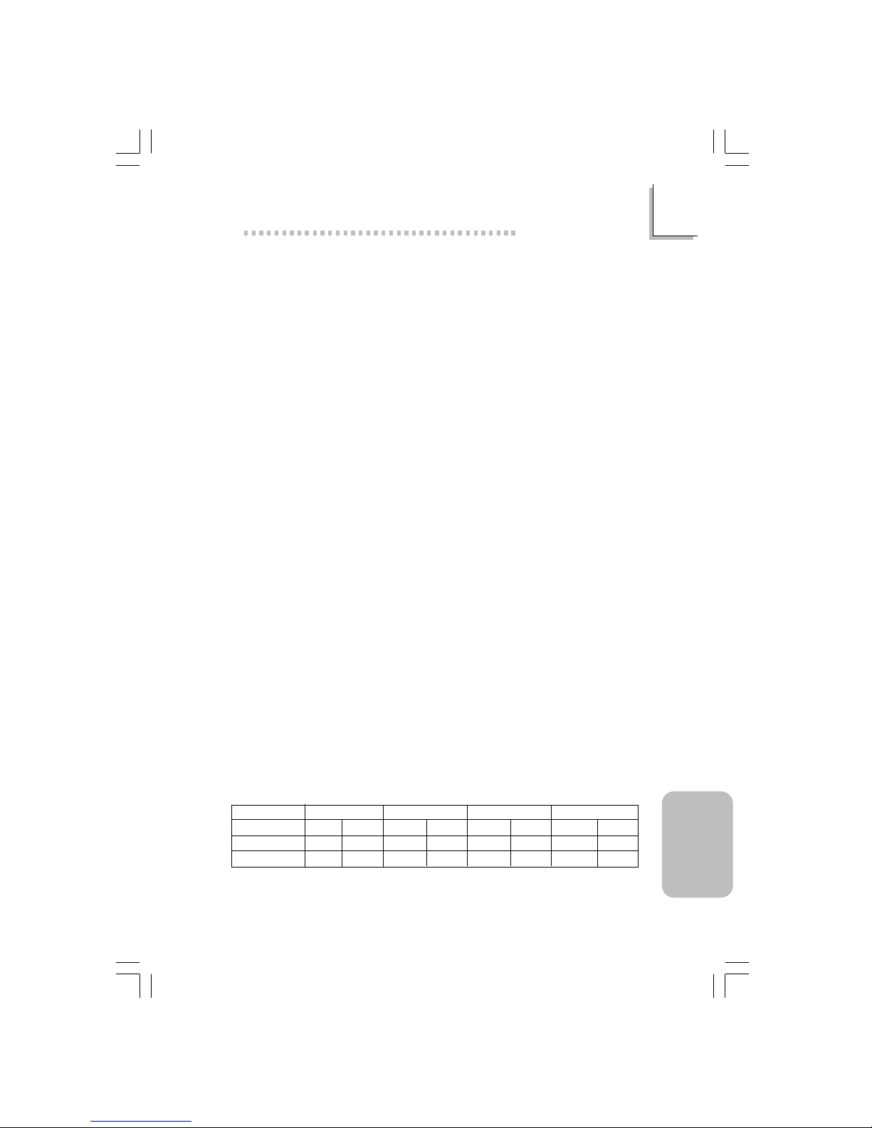
85
5
Español
(Spanish)
Español (Spanish)
5.1 Características y Especificaciones
5.1.1 Características
Chipset
• Intel® 845G chipset
- Hub de Controlador Memoria Gráfica de Intel® 845G
(GMCH)
- Hub de Controlador I/O de Intel® 82801DB (ICH4)
Procesador
La tarjeta madre del sistema esta equipada con un zócalo o enchufe
478 para instalar un procesador Pentium® 4 y procesador Celeron
®
• Procesador Intel® Pentium® 4 (478-terminales)
- 500MHz Canal de datos del sistema - suppor ts up to
2.53 GHz CPU speed
- 400MHz Canal de datos del sistema - supports up to 2.4
GHz CPU speed
• Procesador Intel® Celeron® (478-terminales)
- 400MHz Canal de datos del sistema - supports up to 1.7
GHz CPU speed
Memoria de Sistema
• 2 enchufes de 184-terminales DDR SDRAM DIMM
• PC1600 (DDR200)/PC2100 (DDR266) DDR SDRAM DIMM
de 2.5V sin buffer.
• Apoya un máximo de 2GB memoria de sistema usando la
tecnología de 64Mbit, 128Mbit, 256Mbit o 512Mbit
- No está apoyado con lado doble de x16 DDR SDRAM
DIMM
Anchura de Densidad
184-pin DDR
64 Mbit
X8
SS/DS
64/128MB
X16
SS/DS
32MB/NA
128 Mbit
X8
SS/DS
128/256MB
X16
SS/DS
64MB/NA
256 Mbit
X8
SS/DS
256/512MB
X16
SS/DS
128MB/NA
512 Mbit
X8
SS/DS
512/1024MB
X16
SS/DS
256MB/NA
Densidad
Page 86

86
5
Español
(Spanish)
Español (Spanish)
Ranuras de Expansión
La tarjeta de sistema es equipado con 1 slot AGP/ADD, 6 slots
PCI
La ranura (slot) donde se inser tan las tarjetas solo permite placas
1.5V AGP 4x (1066MB/seg. ancho de banda). AGP es una interfaz
diseñada para sostener tarjetas de gráficos 3D de alto rendimiento.
La misma maneja un gran monto de datos gráficos con las
siguientes características:
• Memoria canalizada de operaciones de lectura y escritura que
ocultan el acceso a la memoria latente.
• Desmultiplicación de direcciones y datos en el canal de datos de
eficiencia próxima al 100%.
El slot ADD es usado para instalar una tarjeta ADD (Mostrador
Digital AGP).
Característica Gráfica Sobre-tarjeta
• Memoria Gráfica
- Compar ta con 512K/1MB/8MB de la memoria de sistema en
modo DOS.
- Usa Tecnología de Memor ia Video Dinámico (DVMT) en
modo Windows
• Controlador Gráfico
- Frecuencia Central de 200MHz
- 350MHz intergrado al 24-bit RAMDAC
- Mostrador Análogo llega al 2048x1536 @ 60Hz refresh
- Instalación de 3D y motor rendimiento – Discreto, Triángulo,
Strips y Fans.
- Mapping de textura correctado per spectivo por pixel.
- Software DVD en 30fps, Pantalla Completa.
• Característica Gráfica de 2D
- Motor de 256-bit BLT optimizado
- Cursor de blendado alfa 32-bit
- Cursor de tr ansparente 3-color programable.
• Característica Gráfica de 3D
- Ritmo Completo de 200 megapixels/sec
- Resolución Máxima de 3D: 1600x1200x32 @ 85Hz
- Flat y Sombra Gouraud
Page 87

87
5
Español
(Spanish)
Español (Spanish)
- 16- y 24-bit Z-buffering y 16- y 24-bit W-buffering
- Ver téx y pixel fogging programable y efecto atmosférico
- Buffer de Rendimiento Doble y Tr iple•
• Drivers de Software
- Windows® 98SE/2000/ME/XP
- WindowsNT® 4.0
Características de Audio En Tablero
• Codec dúplex completo estéreo de 18-bit con independiente
frecuencia de muestreo variable
• Alta calidad de entrada de CD diferencial
• Auténtico salidas de nivel de línea estéreo
• Interfáz de S/PDIF-out
• Output auricular de 2-canal
Características de LAN Interno (NB76-BL sólo)
• Utiliza el rápido controlador Ethernet de Realtek RTL8100
• IEEE 802.3, 10BASE-T integrado y PHY compatible de
100BASE-TX
• Interfaz maestro de 32-bit PCI
• Funciones de administración de energía integrado
• Sopor te dúplex completo en ambos 10 y 100 Mbps
• Soporta auto negociación de IEEE 802.3u
• Soporta alambre par a la administración
Compatibilidad
• Sumisión de Microsoft® PC ’98
• Sumisión de PCI 2.2, CNR 1.0 tipo de “A” y AC’97
• Versión 2.0 de Intel AGP
Puertos de Cubierta Doble de ATX (Conectores de PC 99 colorcifrado)
• 4 puer tos de USB2.0/1.1
• 1 puer tos de RJ45 LAN (NB76-BL sólo)
• 2 puer tos de serie DB-9 NS16C550A-compatible
• 1 puerto de VGA DB-15
• 1 puer to paralelo de DB-25
• 1 puerto de r atón PS/2 mini-DIN-6
• 1 puer to de teclado mini-DIN-6 PS/2
• 3 enchufes de audio: línea de salida, línea de entrada y mic de
entrada
Page 88

88
5
Español
(Spanish)
Español (Spanish)
Conectores
• 1 conector para 2 puer tos de USB2.0/1.1 exter no adicional
• 1 conector para un puerto de serial externa
• 1 conector para un puer to de juego/MIDI exter na
• 2 conectores de audio interno -CD-in, AUX-in, Video-in y TAD
• Conector de 1 S/PDIF-out
• 1 conector para interfaz de IrDA
• 2 conectores de IDE
• 1 conector de disquete sopor ta hasta dos disquetes de 2.88MB
• 2 conector de fuente de alimentación de ATX
• 1 conector de Wake-On-LAN
• 1 conector de Wake-On-Ring
• Conectores de abanicos de CPU, chasis y second
Controlador de IDE Maestro de Bus PCI
• Dos interfaces de PCI IDE sopor ta hasta 4 dispositivos de IDE
• Sopor ta las unidades duras de ATA/33, ATA/66 y ATA/100
• PIO Modo 4 Realzada IDE (tasa de transferencia de dato hasta
14MB/seg.)
• Controlación de Bus reduce la utilización de CPU durante la
trasferencia de disco
• Sopor ta ATAPI CD-ROM, LS-120 y ZIP
S/PDIF
El sistema está equipado con la interfaz de audio digital S/PDIF
(Sony/Philips Interfaz Digital). S/PDIF es un formato de transferencia
de archivo de audio convencional que transfiere señales de audio
digital a un componente sin tener que convertir lo primero a un
formato análogo. Esto evita que la calidad de la señal de audio
pierda calidad cuando es convertido a un for mato análogo.
Page 89

89
5
Español
(Spanish)
Español (Spanish)
Interfaz de IrDA
El tablero de sistema es equipado con el conector de IrDA para la
conexión de radiotelegráfico entre su computadora y dispositivos de
periferia. Soporta dispositivos de periferia que se encuentra con el
estándar de IrDA o ASKIR.
Puertos de USB
La tarjeta sistema apoya con puerto USB 2.0 y USB 1.1, USB lo
permita el cambio de dato entre su computador y un campo ancho
de periferales Plug y Play externo acessíble simultáneamente.
BIOS
• Award BIOS, Windows® 98SE/2000/ME/XP Enchufar y Usar
compatible
• Sopor ta el incio de secuencia de SCSI
• Parpadea EPROM para fácil actualización de BIOS
• Sopor ta la función de DMI 2.0
Interfaz de Administración de Desktop (DMI)
El sistema de tablero viene con DMI 2.0 establecido en el BIOS. La
utilidad del DMI en el BIOS graba automáticamente varias
informaciones sobre la configuración de su sistema y almace estas
informaciones en la balsa de DMI, que es parte del tablero de
sistema Enchufar y Usar BIOS. DMI junto con software de red
apropiado, es diseñado para hacer más fácil el inventario,
mantenimiento y procedimiento para solucionar problema de los
sistemas de computadora.
Page 90
90
5
Español
(Spanish)
Español (Spanish)
5.1.2 Inteligencia
Botón de Energía de Doble Función
Dependiendo en la configuración en el campo de “Soft-Off By PWRBTTN” de la Configuración de Power Management Setup, este
interruptor permite el sistema de entrar al modo de Soft-Off o
Suspender.
Wake-On-Ring
Esta característica permite el sistema que es en el modo de
Suspender o en el modo de Soft Power Off a despier to/encendido
para responder a llamadas que vienen desde un modem interno o
externo.
Importante:
Si usted está utilizando la tarjeta incorporada de modém, el
fuente de energía de 5VSB de su fuente de alimentación debe
soportar ≥720mA.
W a k e-On-LAN
La función de Wake-On-LAN permite el red de despertar
remotamente el PC de Apagar de Soft (Soft-Off) que vienen desde
un tarjeta de LAN. Su tarjeta de LAN debe sopor tar la función de
desper tar remoto.
Importante:
El origen de energía de 5VSB de su fuente de alimentación
debe soportar >720mA.
Teclado de Wake-On / Ratón de Wake-On
Esta función le permite utilizar el teclado o PS/2 ratón para encender
el sistema.
Importante:
• El botón de energía no funcionará una vez quela
contraseña del teclado ha sido configurado en el campo de
“KB Power On Password” del submenú Integrated
Peripherals. Usted debe teclear la contraseña correcta para
encender el sistema. Si se le olvidó la contraseña, apaga su
Page 91

91
5
Español
(Spanish)
Español (Spanish)
sistema y quite la bateria. Espera por unos segundos e
instálalo de vuelta antes de encender el sistema.
• El origen de energía de 5VSB de su fuente de alimentación
debe soportar >720mA.
Teclado de Wake-On-USB
La función “Teclado de Wake-On-USB” le per mite a usted usar un
teclado de USB aparato para desper tar un sistema que esta en el
“S3 (STR-Suspend To RAM)”estado.
Importante:
• Si estas usando las funciones de teclado de Wake-On-USB
para 2 puertos de USB, el 5VSB potencia debe soportar
una corrient (>) mas grande que ≥1.5A.
• Si estas usando las funciones de teclado de Wake-On-USB
para ≥4 puertos de USB, el 5VSB potencia debe soportar
una corrient (>) mas grande que ≥2A.
Temporizador de RTC para Encender el Sistema
El RTC instalado en el tablero de sistema permite su sistema de
encender automáticamente en la fecha y el tiempo configurado.
ACPI STR
El tablero de sistema es diseñado para encontrar con la
especificación de ACPI (Configuración Avanzada e Interfaz de
Energía). ACPI tiene las car acterísticas de archivación de ener gía que
activa PC para ejecutar la Administración de Energía y Enchufar y
Usar con los sistemas operativos que soporta la Administración de
Energía Directa de OS. Corrientemente, sólo Windows® 98SE/2000/
ME/XP soporta la función de ACPI. ACPI cuando activado en la
Power Management Setup le permitirá de utilizar la función de
Suspender a RAM.
Con la función de Suspender a RAM activada, usted puede apagar
el sistema una vez por presionando el botón de energía o
seleccionando “Preparado” cuando apaga el Windows® 98SE/2000/
ME/XP sin tener que ir por el proceso de molesto algunas veces de
Page 92

92
5
Español
(Spanish)
Español (Spanish)
los archivos cerrados., aplicaciones y sistema operativo. Esto es
porque el sistema es capaz de almacenar todos los archivos de
programas y datos durante la sesión operativa entera dentro de
RAM (Memoria de Acceso Casual) cuando es apagado. La sesión
operativa resumirá exactamente donde usted dejará la próxima vez
que encienda la computadora.
Importante:
El origen de energía de 5VSB de su fuente de alimentación
debe soportar ≥1A.
Recuperación de Fracaso de Energía AC
Cuando la energía vuelve después del fracaso de ener gía AC, usted
puede elegir a encender su sistema manualmente, dejar el sistema de
encender automáticamente o volver al estado donde usted dejó
antes de ocurrir el fracaso de energía.
Protección de Virus
La mayoría de los viruses de hoy destroye el dato almacenado en
los discos duros. El tablero de sistema es diseñado para proteger el
sector de inicio y tabla de partición de su unidad de disco duro.
Page 93

93
5
Español
(Spanish)
Español (Spanish)
5.2 Softwares Soportados
5.2.1 El Software Juego de Chip Intel instalación de Utilidad
El Software Juego de Chip Intel instalación de Utilidad es usado
para actualizar archivos de INFORMACIÓN de Windows
98SE/2000/ME/XP para que el juego de chip Intel pueda ser
reconocido y configurado adecuadamente en el sistema.
Para instalar la utilidad, por favor siga los pasos de abajo.
1. Haga clic en “Intel Chipset Software Installation Utility”.
2. Siga los avisos de la pantalla para completar la instalación.
3. Reinicie el sistema para que la utilidad tenga efecto.
5.2.2 Drivers Gráficos de Intel 845G/GL
Para instalar la utilidad, por favor siga los pasos de abajo.
1. Haga clic en “Intel 845G/GL Graphics Driver s”.
2. Siga los avisos de la pantalla para completar la instalación.
3. Reinicie el sistema para que la utilidad tenga efecto.
5.2.3 Drivers de Realtek AC’97 Audio
Drivers de Realtek AC’97 Audio para Windows 98 SE, Windows
ME, Windo ws NT 4.0, Windows 2000 y Windows XP.
Para instalar la utilidad, por favor siga los pasos de abajo.
1. Haga clic en “Realtek AC’97 Audio Drivers”.
2. Siga los avisos de la pantalla para completar la instalación.
3. Reinicie el sistema para que la utilidad tenga efecto.
Page 94

94
5
Español
(Spanish)
Español (Spanish)
5.2.4 Driver de USB 2.0
Drivers de USB 2.0 Soporta Windows 98 SE, Windows ME,
Windows 2000 y Windows XP.
Para instalar la utilidad, por favor siga los pasos de abajo.
1. Haga clic en “USB 2.0 Dr ivers”.
2. Siga los avisos de la pantalla para completar la instalación.
3. Reinicie el sistema para que la utilidad tenga efecto.
5.2.5 Controlador de Realtek LAN Interno (NB76-BL sólo)
Drivers de USB 2.0 Soporta autorun para Windows 98 SE,
Windows ME, Windows 2000 y Windows XP.
Para instalar la utilidad, por favor siga los pasos de abajo.
1. Haga clic en “Realtek LAN Drivers”.
2. Siga los avisos de la pantalla para completar la instalación.
3. Reinicie el sistema para que la utilidad tenga efecto.
El driver de LAN para Windows NT® 4.0 no apoya con “Autorun”.
Mientras el sistema ha descubier to el controlador de ethernet rápido
de Realtek RTL8100, le guiará a instalar el driver para el sistema
operarativo el cual estás usando. Los drivers están en el raíz
directorio “LAN\WINNT4” del CD.
5.2.6 Acelerator de Aplicación Intel
El Acelerator de Aplicación Intel es diseñado a mejorar el
rendimiento del subsistema almacenaje y el rendimiento del sistema
entero. Lo envia el rendimiento mejorado desde varias tecnologías
(componentes) ingredientes.
Para instalar la utilidad, por favor siga los pasos de abajo.
1. Haga clic en “Intel Application Acceler ator”.
2. Siga los avisos de la pantalla para completar la instalación.
3. Reinicie el sistema para que la utilidad tenga efecto.
Page 95

95
5
Español
(Spanish)
Español (Spanish)
5.2.7 Programa de Microsoft DirectX 8.1
Para instalar la utilidad, por favor siga los pasos de abajo.
1. Aparecerá la pantalla de autocorrido (Main Board Utility CD).
Cliquea “Microsoft DirectX 8.1”.
2. Cliquea “Y es” para continuar.
3. Sigue las indicaciones de la pantalla para completar la instalación.
4. Reiniciar el sistema.
5.2.8 McAfee VirusScan Online
El McAfee VirusScan Online es la forma más conveniente y confiable
de proteger su PC de los virus de ordenadores. Cuando instalar el
McAfee VirusScan Online , su ordenador estará protegido pues el lo
escudriñará automáticaticamente los virus y los ponerá al dia de
modo que la protección de su PC mantengase corriente.
Para instalar la utilidad, por favor siga los pasos de abajo.
1. Cliquea “More” de autorun.
2. Aparecerá la pantalla de autocorrido (Main Board Utility CD).
Cliquea “McAfee VirusScan Online”.
3. Cliquea “Y es” para continuar.
4. Sigue las indicaciones de la pantalla para completar la instalación.
5. Reiniciar el sistema.
Page 96

96
5
Español
(Spanish)
Español (Spanish)
5.2.9 Notas de Instalación de Utilidades y Programas
Instaladores
1. El "Autorun" SOLO soporta los sistemas operativos de
Windows® 98 SE, Windows® ME, Windows® 2000, Windows® XP
y Windows NT ® 4.0. Si después de inser tar el CD, el "Autor un"
no iniciará automáticamente (que es, no aparecerá la pantalla de
CD de Main Board Utility), favor de ir directamente al directorio
radical del CD y cliquea doblemente el "Setup".
2. Favor de ir al website de DEFI’s en "http://www.dfi.com/
support1/download2.asp" para la última versión de los
programas instaladores o aplicaciones del software.
3. Todos los pasos o procedimientos para instalar los programas
instaladores de software son sujeto sin avisa, como los softwares
son actualizados ocasionalmente. Favor de consultar los archivos
de readme, si es disponible, para la última información.
Page 97

97
5
Español
(Spanish)
Español (Spanish)
5.3 Investigación de Conflictos
Este capítulo del manual se diseña para ayudarlo con problemas que
usted puede encontrar con su computadora personal. Para
solucionar problemas su sistema eficazmente, trate cada problema
individualmente.
Algunas de las cosas más comunes para verificar cuando usted
encuentra los problemas mientras usando su sistema se listan
debajo.
1. El interruptor de potencia de cada dispositivo periférico ha
encendido.
2. Todos cablegrafían e impulsan se conectan los cordones
herméticamente.
3. La toma de corriente eléctrica a que sus dispositivos periféricos
se conectan está trabajando. Pruebe la toma de corriente
tapando en una lámpara u otro dispositivo eléctrico.
4. El amonestador ha encendido.
5. El brillo de displays y mandos del contraste son propiamente
ajustados.
6. Todo el complemento aborda en las ranuras de expansión se
sienta firmemente.
7. Cualquier tabla del complemento que usted ha instalado se
diseña para su sistema y es correctamente.
Monitor/Display
Si la pantalla del despliegue permanece oscura después de que el
sistema ha encendido.
1. Asegúrese que el interruptor de potencia de monitores es
adelante.
2. Verifique que un fin de los monitores poder cordón se ata
propiamente al amonestador y el otro fin se tapa en una toma
de corriente del C A activa. Si necesario, pruebe otra toma de
corriente.
3. Cheque que el cable de la entrada de video se ata propiamente
al amonestador y el adaptador de pantalla de sistemas.
4. Ajuste el brillo del despliegue volviéndose el amonestador brillo
mando bulto.
Page 98

98
5
Español
(Spanish)
Español (Spanish)
El cuadro constantemente está moviendo.
1. El amonestador ha perdido su sincronización ver tical. Ajuste los
monitores la sincronización vertical.
2. Márchese cualquier objeto, como otro amonestador o abanica
que puede estar creando un campo magnético alrededor del
despliegue.
3. Asegúrese que sus frecuencias de rendimiento de tarjeta de
video son sopor tadas por este amonestador.
La pantalla está vacilándose constantemente.
1. Si el amonestador está cerca de otro amonestador, el
amonestador adyacente puede necesitar ser apagado.
Fluorescentes ligas adyacentes al amonestador la vacilación de la
pantalla puede causar también.
Poder Suplí
Cuando la computadora ha encendido, nada pasa.
1. Verifique que un fin del cordón de poder de CA se tapa en una
toma de corriente viva y el otro fin tapó propiamente en la
par te de atrás del sistema.
2. Asegúrese que el interruptor de selección de voltaje en el
tablero de la parte de atrás es fijo para el tipo correcto de
voltaje que usted está usando.
3. El cordón de poder puede tener un corto o el abr a.. Inspeccione
el cordón e instale un nuevo sí necesario.
Floppy Drive
La computadora no puede acceder el floppy drive.
1. El disquete blando no puede estructurar se. Estructure el disquete
y prueba de nuevo.
2. El disquete puede ser protegido contra escritura. Use un disquete
que no es protegido contra escritura.
3. Usted puede estar escribiendo al paseo malo. Verifique la
declaración del camino para asegurarse que usted está
escribiendo al paseo de la tarjeta.
4. No hay bastante espacio salido en el disquete. Use un disquete
que no es protegido contra escritura.
Page 99

99
5
Español
(Spanish)
Español (Spanish)
Hard Drive
Hard disk fracaso.
1. Asegúrese el tipo del paseo correcto para la unidad de disco
duro se ha entrado en la BIOS.
2. Si el sistema se configura con dos unidades de disco duro,
asegúrese el inicializadle (primero) la unidad de disco duro se
configura como Amo y la segunda unidad de disco duro se
configura como la Esclava. El disco duro principal debe tener una
par tición activa/bootable.
Tempo estructurando muy tiempo.
1. Si su unidad de disco duro toma un período excesivamente
largo de tiempo para estr ucturar, es probable un problema de
conexión de cable. Sin embargo, si su unidad de disco duro tiene
una capacidad grande, tomará un tiempo más largo para
estructurar .
Porto Parallello
La impresora en paralelo que non responden cuando usted
intenta imprimir.
1. Asegúrese que su copiadora ha encendido y que la copiadora es
en línea.
2. Asegúrese que su software se configura para el tipo correcto de
copiadora atado.
3. Verifique que el LPT del onboard que se configuran por tes E/S
dirección y escenas de IRQ correctamente.
4. Verifique que el dispositivo adjunto trabaja atándolo a un puer to
en paralelo que está trabajando y configuró correctamente. Si
funciona, puede asumirse que la copiadora está en la condición
buena. Si la copiadora permanece inoperante, reemplaza el cable
de la copiadora e intenta de nuevo.
Page 100

100
5
Español
(Spanish)
Español (Spanish)
Serial Porta
El dispositivo serie (módem, copiadora) el rendimiento de non
algo o es los outputting falsificaron los caracteres.
1. Asegúrese que los devices de serie impulsan ha encendido y que
el dispositivo es en línea.
2. Verifique que el dispositivo se tapa en el puerto en serie
correcto adelante el trasero de la computadora.
3. Verifique que el dispositivo serie adjunto trabaja atándolo a un
puer to en serie que está tr abajando y configuró correctamente. Si
el dispositivo serie no trabaja, el cable o el dispositivo serie tiene
un problema. Si el dispositivo serie trabaja, el problema puede
ser debido al E/S del onboard o la escena de dirección.
4. Verifique que el COM settings e I/O adress está configurar
correcta.
Keyboard
Nada pasa cuando una llave en el teclado fue apretada.
1. Asegúrese que el teclado se conecta propiamente.
2. Si usted hizo los cambios a las escenas, re-entra en el arreglo y
carga los valores predeterminados.
Sistema Board
1. Asegúrese que la tarjeta del complemento se sienta firmemente
en la ranura de expansión. Si la tarjeta del complemento está
suelta, apagada el sistema, re-instala la tarjeta e impulsa al
sistema.
2. Verifique los valores de conmutadores para asegurar que los
saltadores son propiamente fijos.
3. Verifique que todos los módulos de memoria se sientan
firmemente en las enchufes de memoria.
4. Asegúrese que los módulos de memoria están en las situaciones
correctas.
5. Si la tabla no funciona, pone la tabla en una superficie llana y
sienta todos los componentes del socket. Suavemente apriete
cada componente en el enchufe.
6. Si usted hizo los cambios a las escenas de BIOS, re-entra en el
arreglo y carga los valores predeterminados de BIOS.
 Loading...