

DFI NB72-SR User Manual

NB72-SC
NB72-SR
Rev. A+
System Board
Users Manual
50000123

Copyright
This publication contains information that is protected by copyright.
No part of it may be reproduced in any form or by any means or
used to make any transformation/adaptation without the prior
written permission from the copyright holders.
This publication is provided for informational purposes only. The
manufacturer makes no representations or warranties with respect to
the contents or use of this manual and specifically disclaims any
express or implied warranties of merchantability or fitness for any
particular purpose. The user will assume the entire risk of the use or
the results of the use of this document. Further, the manufacturer
reserves the right to revise this publication and make changes to its
contents at any time, without obligation to notify any person or
entity of such revisions or changes.
© 2001. All Rights Reserved.
Trademarks
Windows® 98, Windows® 98 SE, Windows® ME, Windows® 2000
and Windows NT® 4.0 are registered trademarks of Microsoft
Corporation. Intel® and Pentium® 4 are registered trademarks of
Intel Corporation. Award is a registered trademark of Award
Software, Inc. Other trademarks and registered trademarks of
products appearing in this manual are the properties of their
respective holders.
Caution
To avoid damage to the system:
Use the correct AC input voltage range.
To reduce the risk of electric shock:
Unplug the power cord before removing the system chassis
cover for installation or servicing. After installation or ser vicing,
cover the system chassis before plugging the power cord.

Battery:
Danger of explosion if battery incorrectly replaced.
Replace only with the same or equivalent type recommend by
the manufacturer.
Dispose of used batteries according to the batter y
manufacturers instructions.
Joystick or MIDI port:
Do not use any joystick or MIDI device that requires more than
10A current at 5V DC . There is a risk of fire for devices that
exceed this limit.
FCC and DOC Statement on Class B
This equipment has been tested and found to comply with the limits
for a Class B digital device, pursuant to Part 15 of the FCC rules.
These limits are designed to provide reasonable protection against
harmful interference when the equipment is operated in a residential
installation. This equipment generates, uses and can radiate radio
frequency energy and, if not installed and used in accordance with
the instruction manual, may cause harmful interference to radio
communications. However, there is no guarantee that interference
will not occur in a particular installation. If this equipment does cause
harmful interference to radio or television reception, which can be
determined by turning the equipment off and on, the user is
encouraged to tr y to correct the interference by one or more of the
following measures:
Reorient or relocate the receiving antenna.
Increase the separation between the equipment and the receiver.
Connect the equipment into an outlet on a circuit different from
that to which the receiver is connected.
Consult the dealer or an experienced radio TV technician for
help.
Notice:
1. The changes or modifications not expressly approved by the
party responsible for compliance could void the user's authority
to operate the equipment.
2. Shielded interface cables must be used in order to comply with
the emission limits.

Notice
This users manual contains detailed information about the system
board. If, in some cases, some information doesnt match those
shown in the multilingual manual, the multilingual manual should
always be regarded as the most updated version. The multilingual
manual is included in the system board package.
To view the users manual, insert the CD into a CD-ROM drive. The
autorun screen (Main Board Utility CD) will appear. Click Users
Manual.
System Board
This users manual is for the NB72-SC and NB72-SR system boards.
The differences between these boards are shown below.
NB72-SC
NB72-SR
(Supports RAID)
Promise controller
RAID IDE connectors
RAID LED connector
û
û
û
ü
ü
ü

Table of Contents
Chapter 1 - Introduction
1.1 Features and Specifications..................................................................................
1.2 Package Checklist.........................................................................................................
Chapter 2 - Hardware Installation
2.1 System Board Layout ..........................................................................................
2.2 System Memory...........................................................................................................
2.3 Jumper Settings for Clearing CMOS Data........................................
2.4 Jumper Settings for Wake-On-Keyboard/Mouse..................................
2.5 Jumper Settings for Wake-On-USB Keyboard................................
2.6 Jumper Settings for Selecting the CPUs Front Side Bus......
2.7 Jumper Settings for USB 4................................................................................
2.8 Ports and Connectors...........................................................................................
Chapter 3 - Award BIOS Setup Utility
3.1 The Basic Input/Output System.....................................................................
3.1.1 Standard CMOS Features.............................................................
3.1.2 Advanced BIOS Features..............................................................
3.1.3 Advanced Chipset Features ......................................................
3.1.4 Integrated Peripherals.........................................................................
3.1.5 Power Management Setup............................................................
3.1.6 PnP/PCI Configurations....................................................................
3.1.7 PC Health Status...................................................................................
3.1.8 CPU Frequency Control..................................................................
3.1.9 Load Fail-Safe Defaults.....................................................................
3.1.10 Load Optimized Defaults..............................................................
3.1.11 Set Supervisor Password...............................................................
3.1.12 Set User Password..............................................................................
3.1.13 Save & Exit Setup.................................................................................
3.1.14 Exit Without Saving..............................................................................
7
14
54
54
58
63
66
73
77
79
80
82
82
83
83
84
84
15
17
19
21
23
25
26
27

Introduction
6
95
95
Chapter 4 - Supported Softwares
4.1 Desktop Management Interface.....................................................................
4.2 Hardware Doctor..........................................................................................................
4.3 Intel 845 INF Update Utility for Windows 98/2000/ME...
4.4 Audio Drivers and Software Application...............................................
4.5 Microsoft DirectX 8.0 Driver.............................................................................
4.6 Drivers and Utilities Installation Notes.....................................................
Appendix A - Using the Suspend to RAM
Function
A.1 Using the Suspend to RAM Function........................................................
Appendix B - System Error Messages
B.1 POST Beep.......................................................................................................................
B.2 Error Messages..............................................................................................................
Appendix C - Troubleshooting
C.1 Troubleshooting Checklist....................................................................................
85
88
88
89
89
90
91
97

Introduction
7
1.1 Features and Specifications
1.1.1 Features
Chipset
Intel® 845 chipset
- Intel® 82845 Memory Controller Hub (MCH)
- Intel® 82801BA I/O Controller Hub (ICH2)
Processor
The system board is equipped with Socket 478 for installing a
Pentium® 4 processor.
Intel® Pentium® 4 processor (478-pin)
400MHz system data bus
System Memory
Three 168-pin PC SDRAM DIMM sockets
Suppor ts 3GB system memory
- Uses 64Mbit, 128Mbit, up to 1.5GB using 256Mbit or up to
3GB using 512Mbit technology, PC-100/PC-133 PC SDRAM
DIMM
Supports ECC function
Chapter 1 - Introduction
DIMMs
2MBx64/x72
4MBx64/x72
8MBx64/x72
Memory Size
16MB
32MB
64MB
DIMMs
16MBx64/x72
32MBx64/x72
64MBx64/x72
Memory Size
128MB
256MB
512MB

Introduction
8
Expansion Slots
The system board is equipped with 1 AGP slot, 4 dedicated PCI
slots and 1 shared PCI/CNR slot.
The AGP slot only supports 1.5V AGP 4x (1066MB/sec. bandwidth)
add-in cards. AGP is an interface designed to support high
performance 3D graphics cards for 3D graphics applications. It
handles large amounts of graphics data with the following features:
Pipelined memory read and write operations that hide memory
access latency.
Demultiplexing of address and data on the bus for nearly 100
percent efficiency.
CNR (Communication and Networking Riser) is an interface that
supports multi-channel audio, V.90 analog modem, phone-line based
networking or 10/100 Ethernet based networking riser board.
Onboard Audio Features
18-bit stereo full-duplex codec with independent variable sam-
pling rate
High quality differential CD input
True stereo line level outputs
Compatibility
Microsoft PC 98 compliant
PCI 2.2, CNR 1.0 A type and AC 97 compliant
Intel AGP version 2.0
ATX Double Deck Ports (PC 99 color-coded connectors)
Two USB ports
Two NS16C550A-compatible DB-9 serial por ts
One SPP/ECP/EPP DB-25 parallel port
One mini-DIN-6 PS/2 mouse port
One mini-DIN-6 PS/2 keyboard port
One game/MIDI port
Three audio jacks: line-out, line-in and mic-in

Introduction
9
Connectors
One connector for 2 additional external USB ports
One connector for IrDA interface
Two IDE connectors
Two RAID IDE connectors (NB72-SR)
One floppy drive interface supports up to two 2.88MB floppy
drives
Three ATX power supply connectors
One Wake-On-LAN connector
One Wake-On-Ring connector
CPU, system and second fan connectors
Two internal audio connectors (CD-in and TAD)
ATA RAID - Redundant Array of Inexpensive Disk (NB72-SR)
RAID 0 (striping) or RAID 1 (mirroring) - RAID 0 and RAID 1
cannot coexist
Two independent IDE channels support up to 4 drives (UDMA
modes 33/66/100 or EIDE)
Suppor ts PIO modes 0/1/2/3/4, DMA modes 0/1/2 and
UDMA modes 0/1/2/3/4/5
PCI Bus Master IDE Controller
Two PCI IDE interfaces support up to four IDE devices
Supports ATA/33, ATA/66 and ATA/100 hard drives
PIO Mode 4 Enhanced IDE (data transfer rate up to 14MB/sec.)
Bus mastering reduces CPU utilization during disk transfer
Supports ATAPI CD-ROM, LS-120 and ZIP
IrDA Interface
The system board is equipped with an IrDA connector for wireless
connectivity between your computer and peripheral devices. It
supports peripheral devices that meet the IrDA or ASKIR standard.
USB Ports
The system board supports 4 USB por ts. Two onboard USB por ts
are located at the ATX double deck ports of the board. The J16
connector on the system board allows you to connect the optional
3rd and 4th USB ports. These optional USB ports, which are

Introduction
10
mounted on a card-edge bracket, will be provided as an option.
USB allows data exchange between your computer and a wide
range of simultaneously accessible external Plug and Play peripherals.
BIOS
Award BIOS, Windows® 98/2000/ME Plug and Play compatible
Supports SCSI sequential boot-up
Flash EPROM for easy BIOS upgrades
Supports DMI 2.0 function
Desktop Management Interface (DMI)
The system board comes with a DMI 2.0 built into the BIOS. The
DMI utility in the BIOS automatically records various information
about your system configuration and stores these information in the
DMI pool, which is a part of the system board's Plug and Play
BIOS. DMI, along with the appropriately networked software, is
designed to make inventory, maintenance and troubleshooting of
computer systems easier. Refer to chapter 4 for instructions on using
the DMI utility.
1.1.2 System Health Monitor Functions
The system board is capable of monitoring the following system
health conditions.
Monitors CPU/system temperature and overheat alarm
Monitors 5VSB/VBAT/3.3V/5V/±12V/CPU voltages and failure
alarm
Monitors the fan speed of the CPU fan, system fan and second
fan; and failure alarm
Automatic system fan and second fan on/off control
Read back capability that displays temperature, voltage and fan
speed
Refer to the PC Health Status section in chapter 3 and the
Hardware Doctor section in chapter 4 for more information.

Introduction
11
1.1.3 Intelligence
Automatic System/Second Fan Off
The system and second fans will automatically turn off once the
system enters the Suspend mode.
Dual Function Power Button
Depending on the setting in the Soft-Off By PWR-BTTN field of
the Power Management Setup, this switch will allow the system to
enter the Soft-Off or Suspend mode.
Wake-On-Ring
This feature allows the system that is in the Suspend mode or Soft
Power Off mode to wake-up/power-on to respond to calls coming
through an internal or external modem. Refer to Wake-On-Ring
Connector in chapter 2 and Resume On Ring in the Power
Management Setup section in chapter 3 for more information.
Important:
If you are using a modem add-in card, the 5VSB power source
of your power supply must support ≥720mA.
Wake-On-LAN
The Wake-On-LAN function allows the network to remotely wake
up a Soft Power Down (Soft-Off) PC . Your LAN card must support
the remote wakeup function. Refer to Wake-On-LAN Connector in
chapter 2 and Resume On LAN in the Power Management Setup
section in chapter 3 for more information.
Important:
The 5VSB power source of your power supply must support
≥
720mA.

Introduction
12
Wake-On-Keyboard/Wake-On-Mouse
This function allows you to use the keyboard or PS/2 mouse to
power-on the system. Refer to Jumper Settings for Wake-OnKeyboard/Wake-On-Mouse in chapter 2 and Keyboard/Mouse
Power On in the Integrated Peripherals section in chapter 3 for
more information.
Important:
The power button will not function once a keyboard
password has been set in the KB Power On Password
field of the Integrated Peripherals submenu. You must type
the correct password to power-on the system. If you forgot
the password, power-off the system and remove the
battery. Wait for a few seconds and install it back before
powering-on the system.
The 5VSB power source of your power supply must
support ≥720mA.
Wake-On-USB Keyboard
The Wak e-On -USB Keyboard function allows you to use a USB
keyboard to wake up a system that is in the S3 (STR - Suspend To
RAM) state. Refer to Jumper Settings for Wake-On-USB Keyboard
in chapter 2 and USB KB Wake-Up From S3 in the Power
Management Setup section in chapter 3 for more information.
Important:
If you are using the Wake-On-USB Keyboard function for 2
USB ports, the 5VSB power source of your power supply
must support ≥1.5A.
If you are using the Wake-On-USB Keyboard function for 4
USB ports, the 5VSB power source of your power supply
must support ≥2A.
RTC Timer to Power-on the System
The RTC installed on the system board allows your system to
automatically power-on on the set date and time. Refer to Resume
By Alarm in the Power Management Setup section in chapter 3 for
more information.

Introduction
13
ACPI STR
The system board is designed to meet the ACPI (Advanced
Configuration and Power Interface) specification. ACPI has energy
saving features that enables PCs to implement Power Management
and Plug-and-Play with operating systems that support OS Direct
Power Management. Currently, only Windows® 98/2000/ME suppor ts
the ACPI function. ACPI when enabled in the Power Management
Setup will allow you to use the Suspend to RAM function.
With the Suspend to RAM function enabled, you can power-off the
system at once by pressing the power button or selecting Standby
when you shut down Windows® 98/2000/ME without having to go
through the sometimes tiresome process of closing files, applications
and operating system. This is because the system is capable of
storing all programs and data files during the entire operating session
into RAM (Random Access Memory) when it powers-off. The
operating session will resume exactly where you left off the next time
you power-on the system. Refer to Using the Suspend to RAM
Function in appendix A for more information.
Important:
The 5VSB power source of your power supply must support
≥
1A.
AC Power Failure Recovery
When power returns after an AC power failure, you may choose to
either power-on the system manually, let the system power-on
automatically or return to the state where you left off before power
failure occurs. Refer to PWR Lost Resume State in the Integrated
Peripherals section in chapter 3 for more information.
Year 2000 Compliant
Supports hardware Y2K function.
Supports hardware Random Number Generator (RNG) to en-
able a new security and manageability infrastructure for PC.

Introduction
14
Virus Protection
Most viruses today destroy data stored in hard drives. The system
board is designed to protect the boot sector and partition table of
your hard disk drive.
1.2 Package Checklist
The system board package contains the following items:
þ The system board
þ A users manual
þ One IDE cable for ATA/33, ATA/66 or ATA/100 IDE drives
(NB72-SC)
Three IDE cables for ATA/33, ATA/66 or ATA/100 IDE drives
(NB72-SR)
þ One 34-pin floppy disk drive cable
þ One RAID Driver floppy diskette (NB72-SR)
þ One Main Board Utility CD
If any of these items are missing or damaged, please contact your
dealer or sales representative for assistance.
Hardware Installation
15
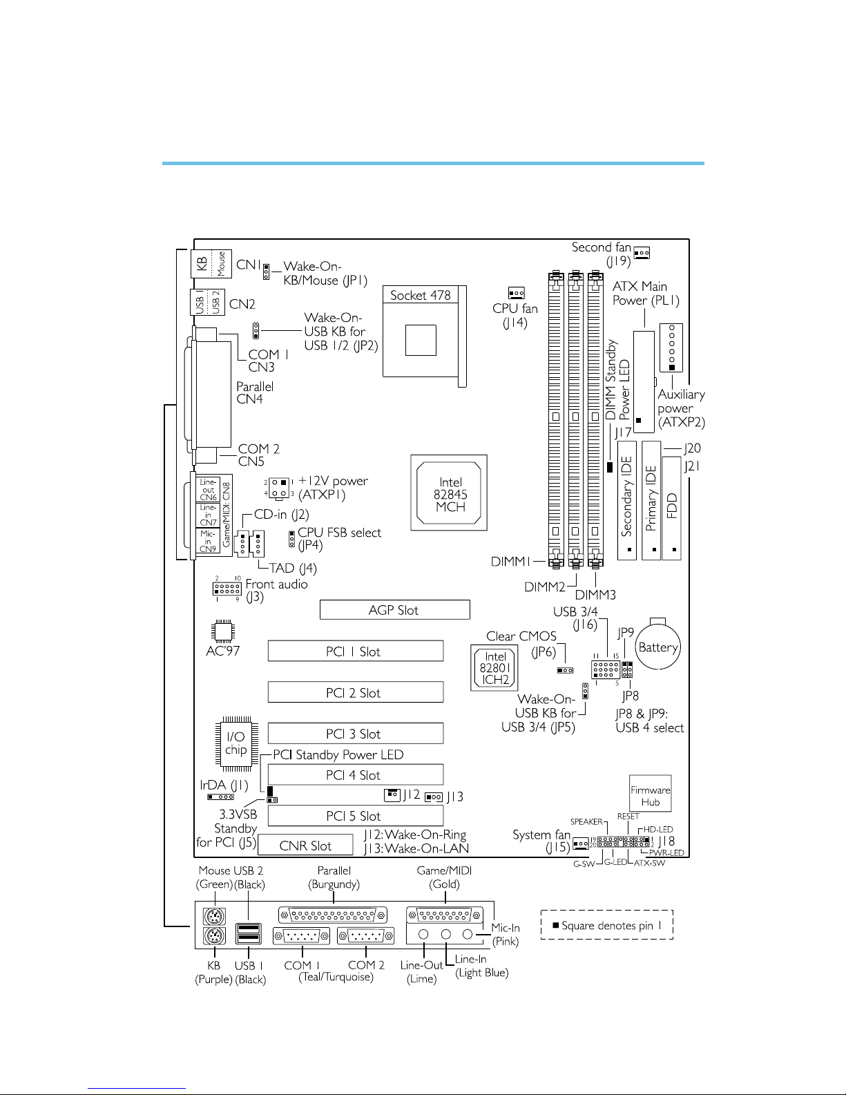
2.1 System Board Layout
Chapter 2 - Hardware Installation
NB72-SC
16
Hardware Installation
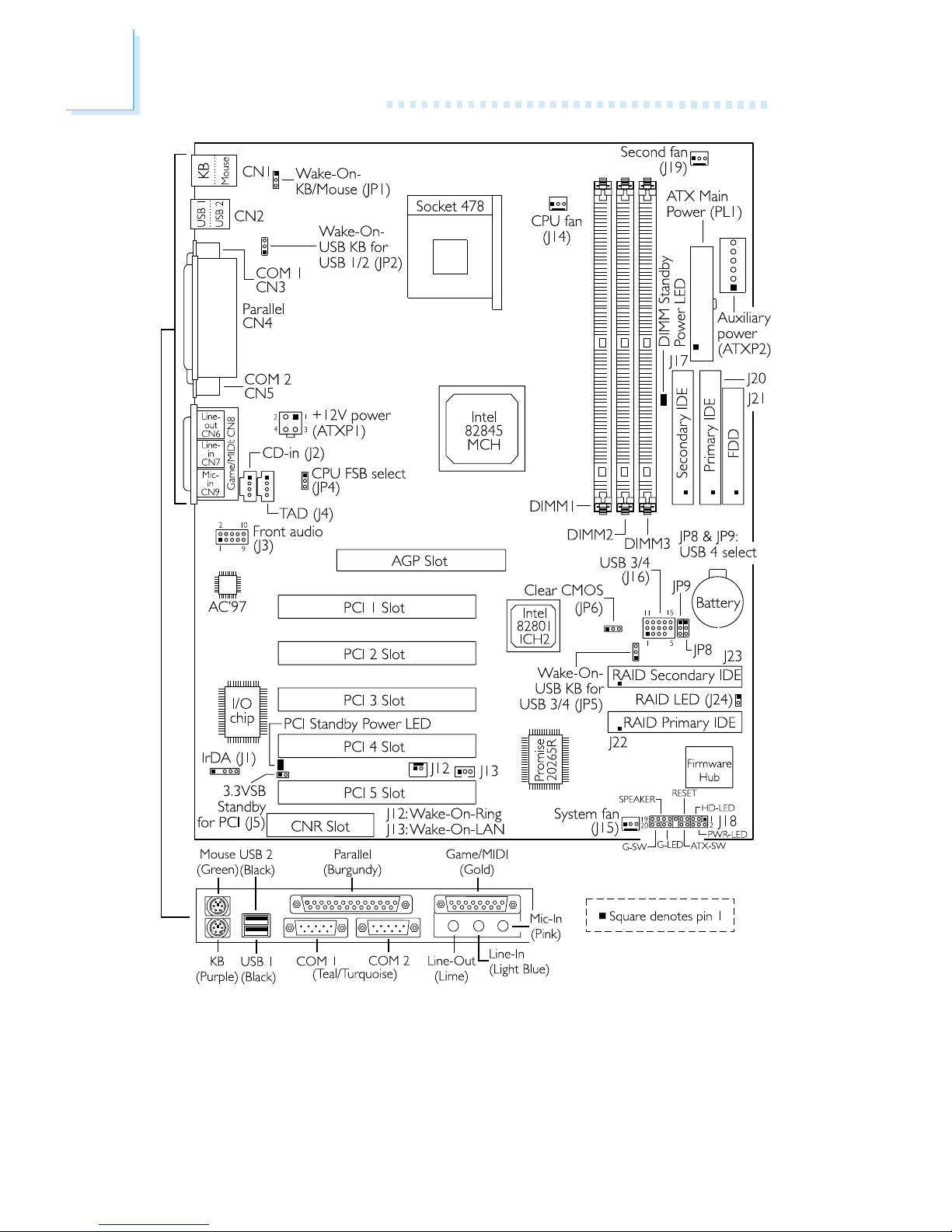
NB72-SR
(Supports RAID)

Hardware Installation
17
2.2 System Memory
Warning:
Electrostatic discharge (ESD) can damage your system board,
processor, disk drives, add-in boards, and other components. Perform
the upgrade instruction procedures described at an ESD workstation
only. If such a station is not available, you can provide some ESD
protection by wearing an antistatic wrist strap and attaching it to a
metal part of the system chassis. If a wrist strap is unavailable,
establish and maintain contact with the system chassis throughout
any procedures requiring ESD protection.
The system board is equipped with three 168-pin DIMM (Dual Inline Memory Module) sockets that support unbuffered PC-133/PC100 SDRAM DIMM for 133MHz/100MHz system memory bus. PC
SDRAM (Synchronous Dynamic Random Access Memory) is a fast
memory interface technology that uses the clock on the chip to
synchronize with the CPU clock so that the timing of the memory
chips and the timing of the CPU are synchronized. This saves time
during transmission of data, subsequently increasing system
performance.
The system board also supports the ECC (Error Checking and
Correction) function. To use this function, you must install DIMM that
supports parity. Refer to chapter 1 (System Memor y section) for
18
Hardware Installation
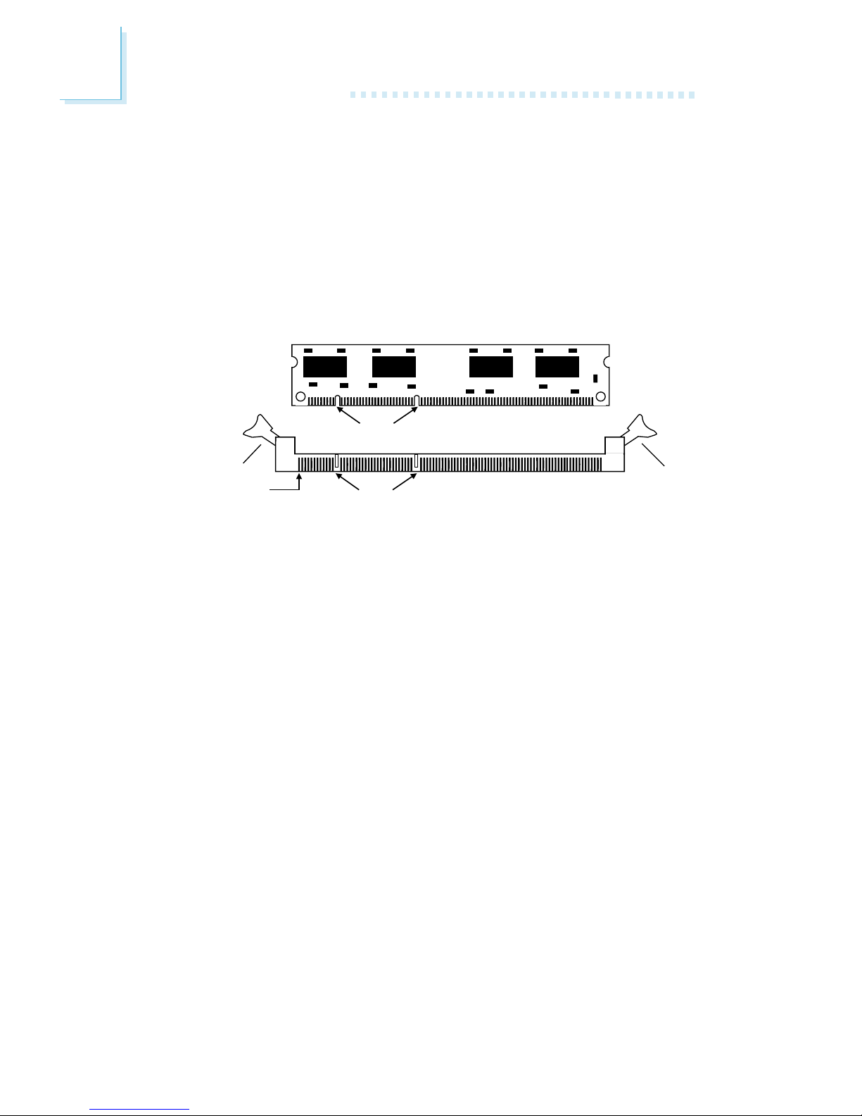
1. Pull the tabs which are at the ends of the socket to the side.
2. Position the DIMM above the socket with the notches in the
module aligned with the keys on the socket.
3. Seat the module vertically into the socket. Make sure it is
completely seated. The tabs will hold the DIMM in place.
Pin 1
Notch
Key
Tab
Tab
2.2.1 Installing the DIM Module
A DIM module simply snaps into a DIMM socket on the system
board. Pin 1 of the DIM module must correspond with Pin 1 of the
socket.
detailed specification of the memory supported by the system
board. Memory Frequency For in the Advanced Chipset Features
submenu of the BIOS must be set accordingly.
Hardware Installation
19
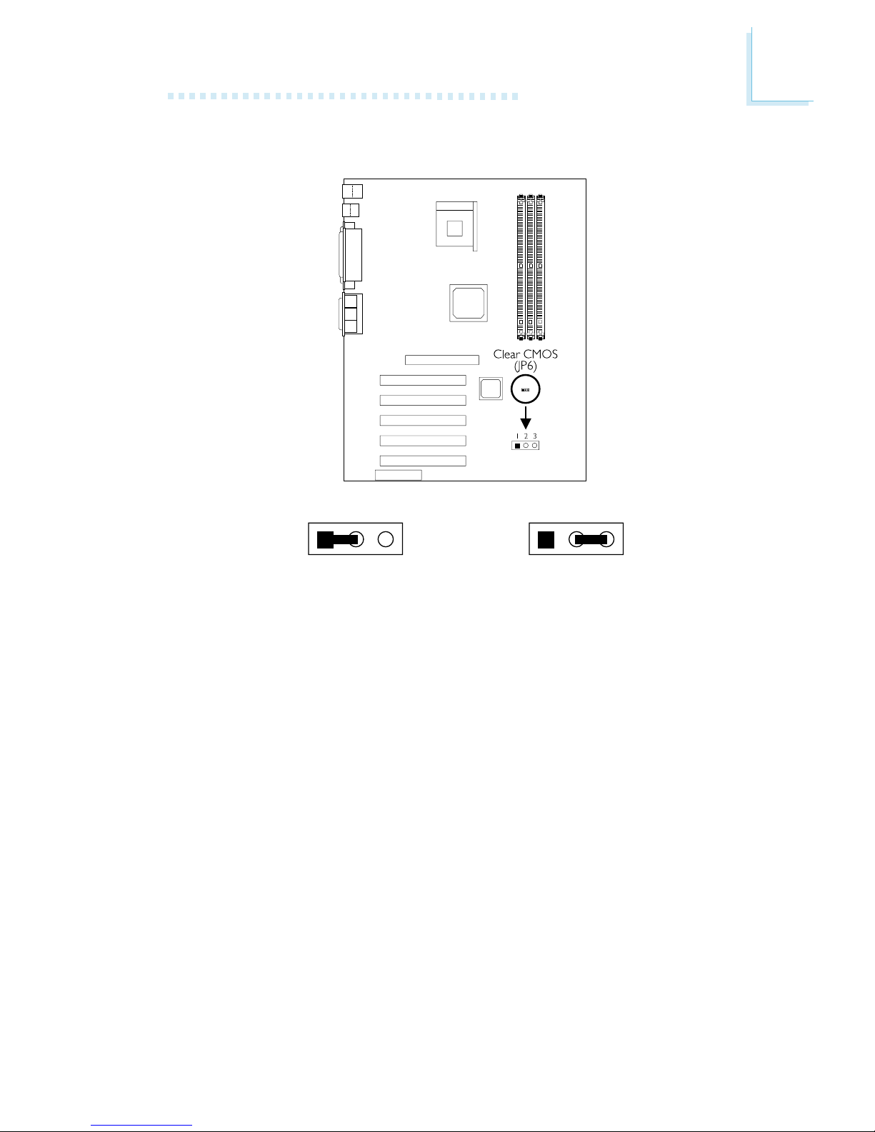
2.3 Jumper Settings for Clearing CMOS Data
Clear CMOS Data - Jumper JP6
If you encounter the following,
a) CMOS data becomes corrupted.
b) You forgot the supervisor or user password.
c) You are unable to boot-up the computer system because the
processors ratio/clock was incorrectly set in the BIOS.
you can reconfigure the system with the default values stored in the
ROM BIOS.
To load the default values stored in the ROM BIOS, please follow
the steps below.
1. Power-off the system.
2. Set JP6 pins 2 and 3 to On. Wait for a few seconds and set JP6
back to its default setting, pins 1 and 2 On.
2-3 On:
Clear CMOS Data
1-2 On: Normal
(default)
1
23
1
23

20
Hardware Installation
3. Now power-on the system.
If your reason for clearing the CMOS data is due to incorrect
setting of the processors ratio/clock in the BIOS, please proceed
to step 4.
4. After powering-on the system, press <Del> to enter the main
menu of the BIOS.
5. Select the CPU Frequency Control submenu and press <Enter>.
6. Set the CPU Clock Ratio or Clock By Slight Adjust field to its
default setting or an appropriate frequency ratio or bus clock.
Refer to the CPU Frequency Control section in chapter 3 for
more information.
7. Press <Esc> to return to the main menu of the BIOS setup
utility. Select Save & Exit Setup and press <Enter>.
8. Type <Y> and press <Enter>.
Hardware Installation
21
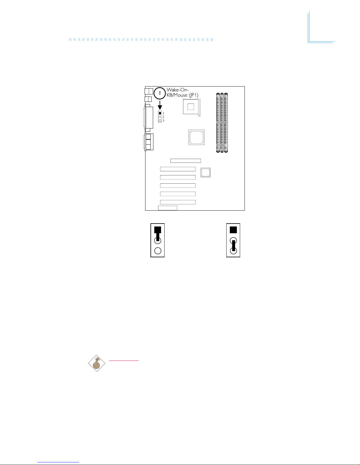
2.4 Jumper Settings for Wake-On-Keyboard/
Wake-On-Mouse
Wake-On-Keyboard/Wake-On-Mouse - Jumper JP1
The Wake-On-Keyboard/Wake-On-Mouse function allows you to use
the keyboard or PS/2 mouse to power-on the system. By default,
JP1 is disabled. To use this function, set JP1 to 2-3 On. Keyboard/
Mouse Power On in the Integrated Peripherals submenu of the
BIOS must be set accordingly. Refer to chapter 3 for details.
Warning:
1. If JP1 was enabled with a password set in the KB Power
On Password field, and now you wish to disable the
keyboard password function, make sure to set the
Keyboard/Mouse Power On field to Disabled prior to
setting JP1 to disabled. You will not be able to boot up the
system if you fail to do so.
2-3 On: Enable
1-2 On: Disable
(default)
1
2
3
1
2
3

22
Hardware Installation
2. The power button will not function once a keyboard
password has been set in the KB Power On Password
field of the Integrated Peripherals submenu. You must type
the correct password to power-on the system.
3. The 5VSB power source of your power supply must
support ≥720mA.
Hardware Installation
23
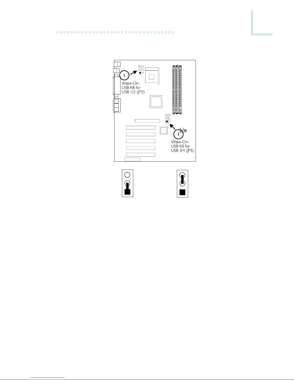
2.5 Jumper Settings for Wake-On-USB Keyboard
2-3 On: Enable1-2 On: Disable
(default)
Wake-On-USB Keyboard for USB 1 and 2 - JP2
Wake-On-USB Keyboard for USB 3 and 4 - JP5
The Wak e-On -USB Keyboard function allows you to use a USB
keyboard to wake up a system that is in the S3 (STR - Suspend To
RAM) state.
By default, this function is disabled. To use this function, JP2 and JP5 pins 2 and 3 must be set to On. USB KB Wake-Up From S3 in
the Power Management Setup submenu of the BIOS must also be
enabled.
3
2
1
3
2
1

24
Hardware Installation
Important:
If you are using the Wake-On-USB Keyboard function for 2
USB ports, the 5VSB power source of your power supply
must support ≥1.5A.
If you are using the Wake-On-USB Keyboard function for 4
USB ports, the 5VSB power source of your power supply
must support ≥2A.
Hardware Installation
25
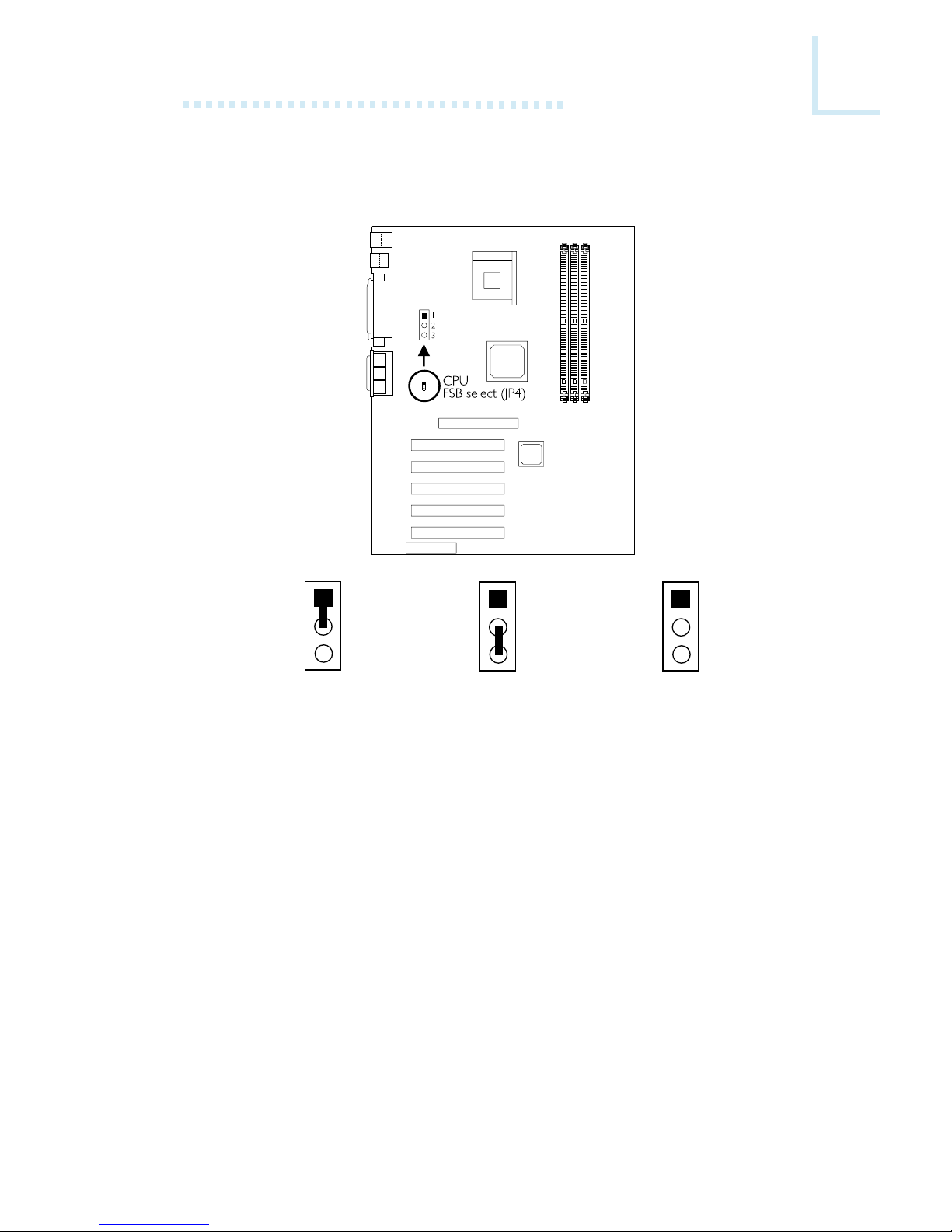
2.6 Jumper Settings for Selecting the CPUs Front
Side Bus
CPU Front Side Bus Select - Jumper JP4
This jumper is used to select the front side bus of the processor
installed on the system board.
2-3 On: 100MHz1-2 On: Auto
(default)
1
2
3
1
2
3
All Off: 133MHz
1
2
3
26
Hardware Installation
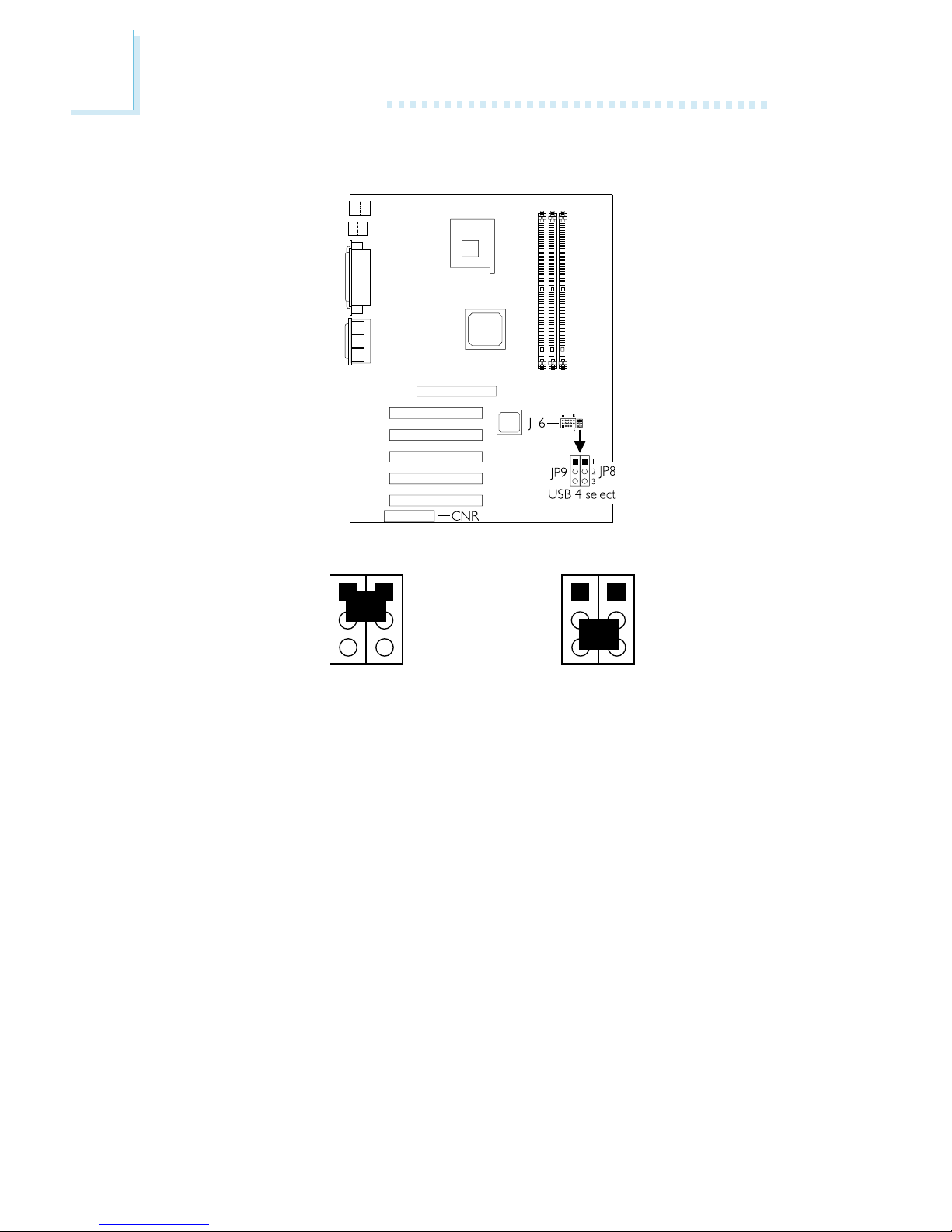
2.7 Jumper Settings for USB 4
1
2
3
JP9 JP8
1-2 On: USB 4 on J16
(default)
2-3 On: USB 4 on CNR
USB 4 Select - Jumpers JP8 and JP9
These jumpers are used to select USB 4s location. Set pins 1 and 2
to On if you want USB 4 on J16. Set pins 2 and 3 to On if you
want USB 4 on CNR.
1
2
3
JP9 JP8
Hardware Installation
27
2.8 Ports and Connectors
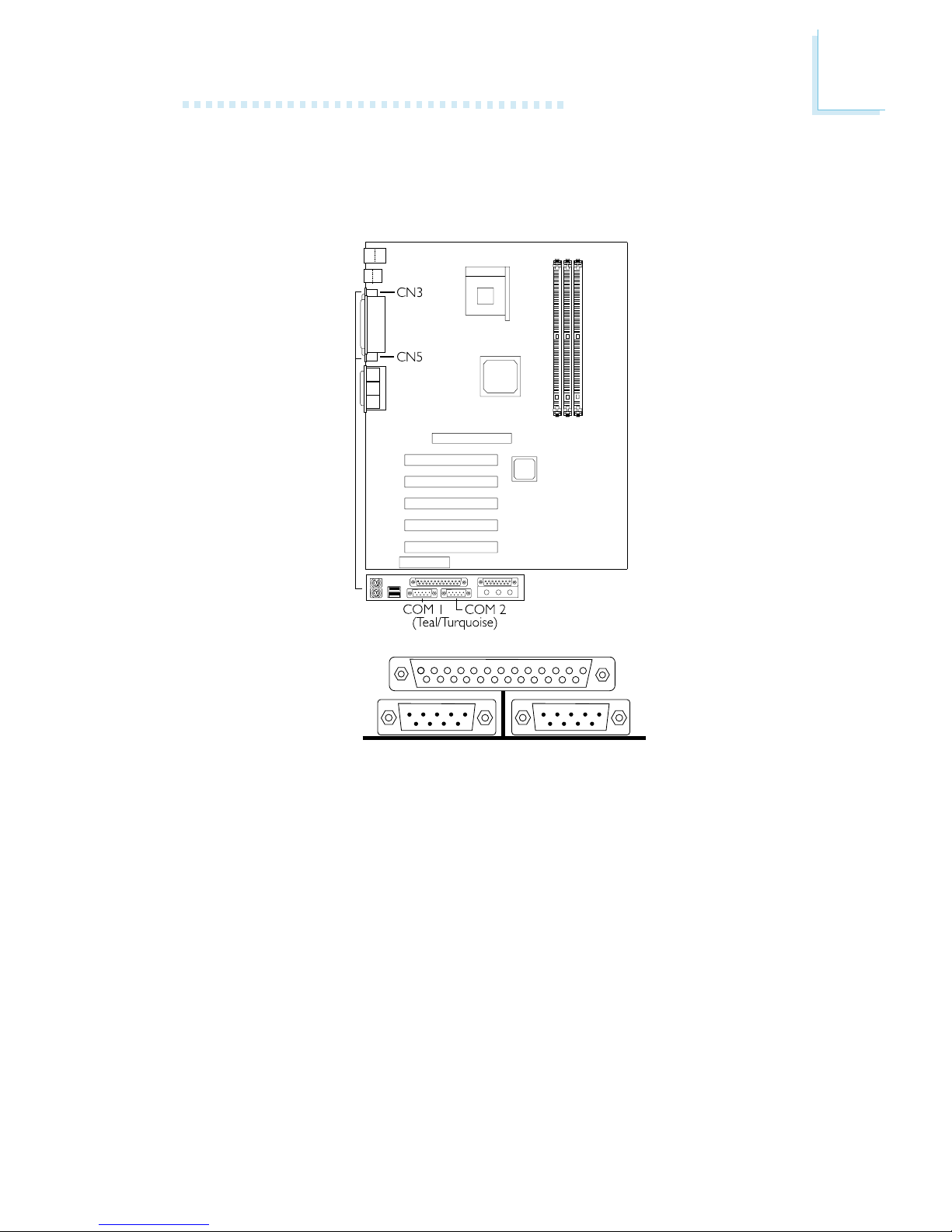
2.8.1 Serial Ports
COM 1
Serial Port
COM 2
Serial Port
The system board is equipped with onboard serial ports (COM 1:
CN3 and COM 2: CN5) - both in Teal/Turquoise color located at
the ATX double deck ports of the board.
These ports are RS-232C asynchronous communication por ts with
16C550A-compatible UARTs that can be used with modems, serial
printers, remote display terminals, and other serial devices. You can
set the serial ports I/O address in the Integrated Peripherals
submenu of the BIOS.
28
Hardware Installation
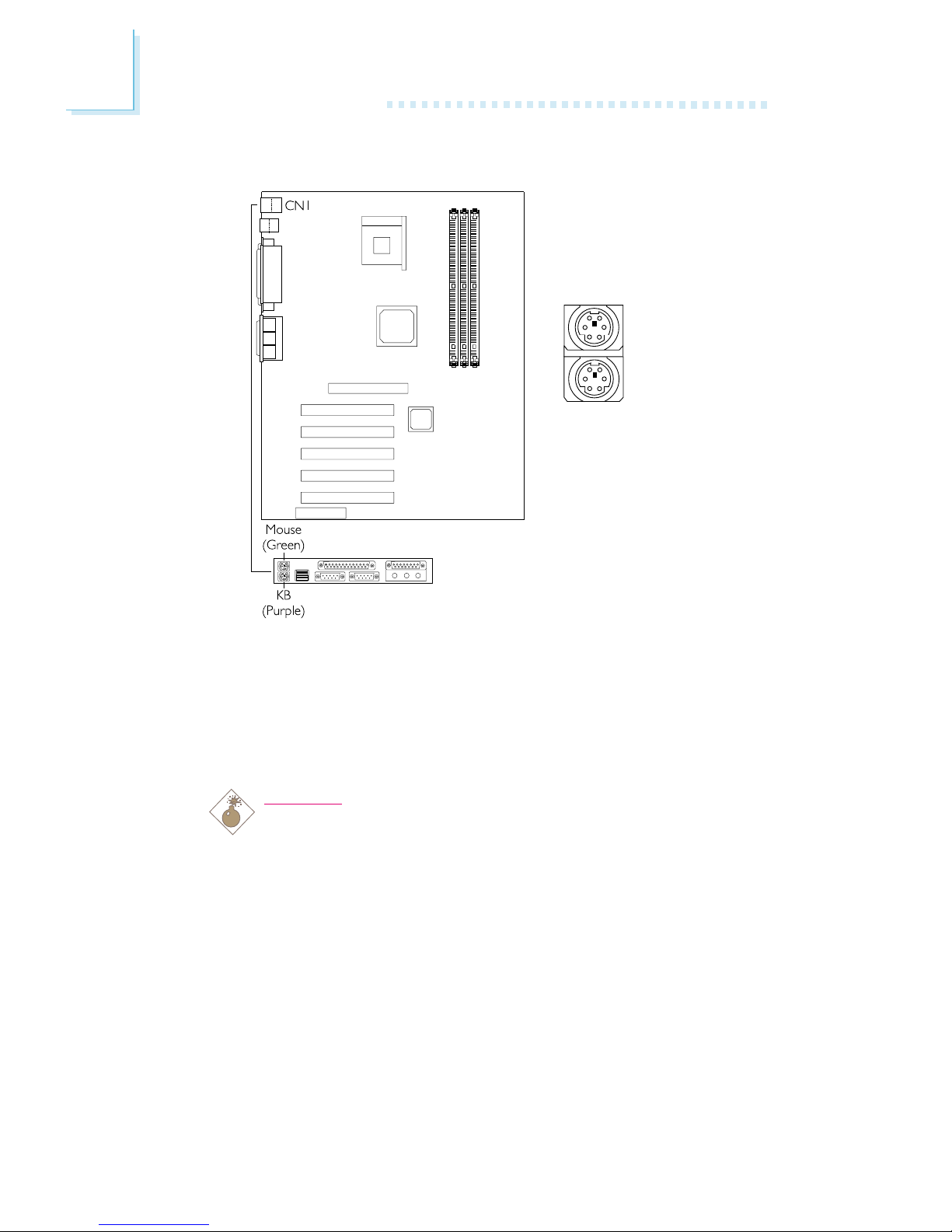
2.8.2 PS/2 Mouse and PS/2 Keyboard Ports
PS/2 Mouse
PS/2 Keyboard
The system board is equipped with an onboard PS/2 mouse
(Green) and PS/2 keyboard (Purple) por ts - both at location CN1
of the ATX double deck ports of the system board. The PS/2
mouse por t uses IRQ12. If a mouse is not connected to this port,
the system will reserve IRQ12 for other expansion cards.
Warning:
Make sure to turn off your computer prior to connecting or
disconnecting a mouse or keyboard. Failure to do so may
damage the system board.
Hardware Installation
29
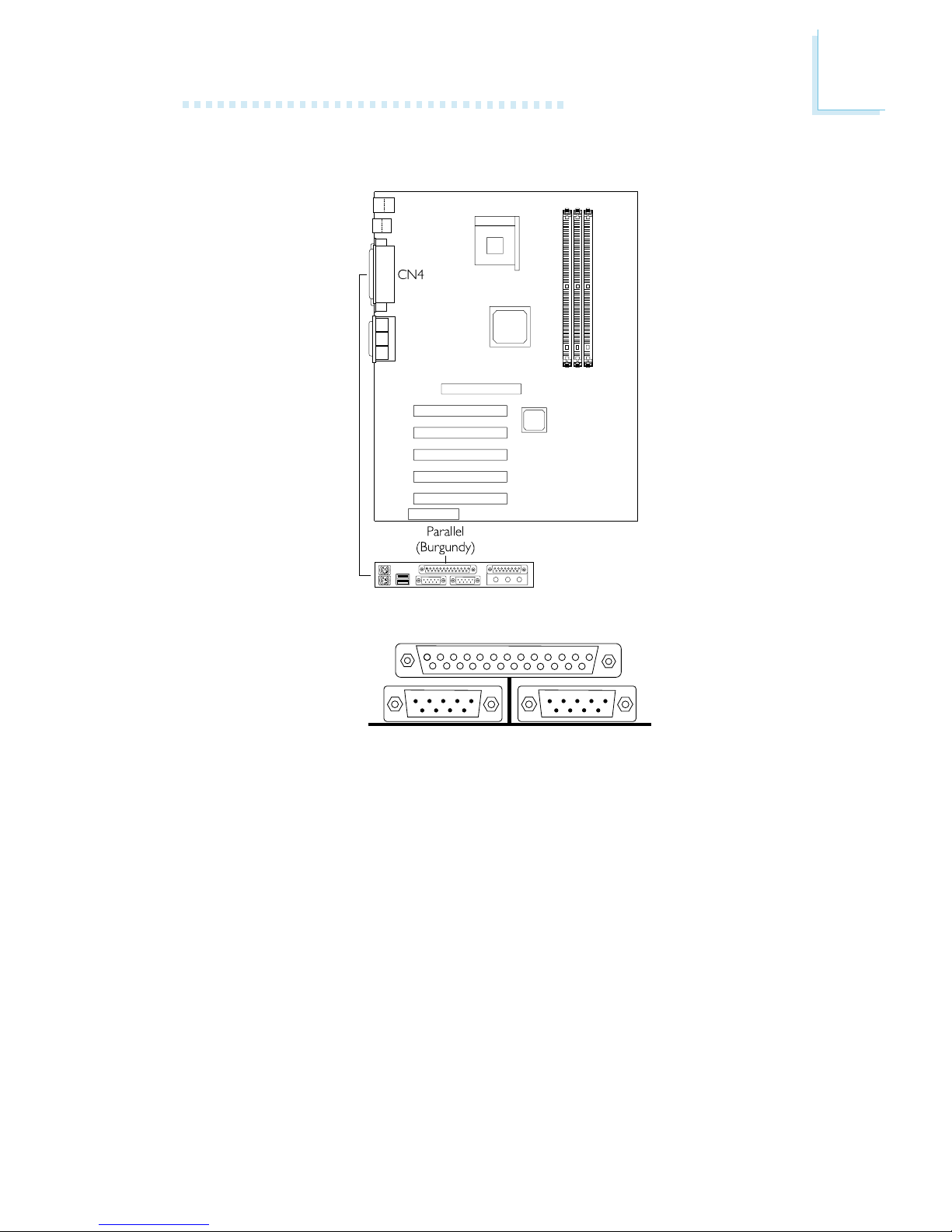
2.8.3 Parallel Port
The system board has a standard parallel port (CN4 - Burgundy)
located at the ATX double deck ports of the board for interfacing
your PC to a parallel printer. It supports SPP, ECP, EPP and PntMode
modes. You can select the ports mode in the Integrated Peripherals
submenu of the BIOS.
Parallel Por t

30
Hardware Installation
Setting
SPP
(Standard Parallel Port)
ECP
(Extended Capabilities Port)
EPP
(Enhanced Parallel Por t)
PntMode
Function
Allows normal speed operation but
in one direction only.
Allows parallel port to operate in
bidirectional mode and at a speed
faster than the SPPs data transfer
rate.
Allows bidirectional parallel port operation at maximum speed.
Allows parallel port to operate in
bipolar mode.
 Loading...