

Page 1
1
Chapter 1 Introduction
MD711-SU
Medical Computing System
User’s Manual
A48700809
Page 2

2
Chapter 1 Introduction
Copyright
This publication contains information that is protected by copyright. No part of it may be reproduced in any form or by any means or used to make any transformation/adaptation without
the prior written permission from the copyright holders.
This publication is provided for informational purposes only. The manufacturer makes no
representations or warranties with respect to the contents or use of this manual and specifically disclaims any express or implied warranties of merchantability or fitness for any particular
purpose. The user will assume the entire risk of the use or the results of the use of this document. Further, the manufacturer reserves the right to revise this publication and make changes
to its contents at any time, without obligation to notify any person or entity of such revisions
or changes.
Changes after the publication’s first release will be based on the product’s revision. The website
will always provide the most updated information.
© 2018. All Rights Reserved.
Trademarks
Product names or trademarks appearing in this manual are for identification purpose only and
are the properties of the respective owners.
FCC and DOC Statement on Class B
This equipment has been tested and found to comply with the limits for a Class B digital
device, pursuant to Part 15 of the FCC rules. These limits are designed to provide reasonable protection against harmful interference when the equipment is operated in a residential
installation. This equipment generates, uses and can radiate radio frequency energy and, if not
installed and used in accordance with the instruction manual, may cause harmful interference
to radio communications. However, there is no guarantee that interference will not occur in a
particular installation. If this equipment does cause harmful interference to radio or television
reception, which can be determined by turning the equipment off and on, the user is encouraged to try to correct the interference by one or more of the following measures:
• Reorient or relocate the receiving antenna.
• Increase the separation between the equipment and the receiver.
• Connect the equipment into an outlet on a circuit different from that to which the receiver
is connected.
• Consult the dealer or an experienced radio TV technician for help.
Page 3

3
Chapter 1 Introduction
The MD711 Medical Computing System has been tested and complies with the regulatory safety
requirements and design standards of the following:
EN 60601-1:2006
Medical electrical equipment - Part 1: General requirements for basic safety and essential
performance
IEC 60601-1-2:2014 and/or EN 60601-1-2:2015
Medical electrical equipment. General requirements for basic safety and essential performance.
Collateral Standard. Electromagnetic disturbances. Requirements and tests
Page 4

4
Chapter 1 Introduction
Table of Contents
About this Manual .................................... 5
Warranty ................................................. 5
Static Electricity Precautions ..................... 5
Safety Measures....................................... 5
Safety Precautions ................................... 6
About the Package ................................... 7
Before Using the System .......................... 7
Chapter 1 - Introduction ........................... 8
Overview .................................................................................8
Key Features ...........................................................................8
Specifications ...........................................................................9
Getting to Know the MD711-SU ..............................................10
Mechanical Dimensions ..........................................................11
Chapter 2 - Getting Started ...................... 12
Chapter 3 - Installing Devices ................... 13
Removing the Chassis Cover ...................................................13
Installing a 2.5” SATA Drive....................................................13
Installing a SODIMM .............................................................. 14
Chapter 4 - Jumper Settings ..................... 17
Clear CMOS Data ................................................................... 17
Chapter 5 - Ports and Connectors ............. 18
Front Panel I/O Ports .............................................................18
Rear Panel I/O Ports ..............................................................18
USB Ports................................................................................ 19
Audio Ports .............................................................................. 19
COM Ports ............................................................................... 20
RJ45 LAN Ports ........................................................................ 21
DC-in ...................................................................................... 21
Display Outputs ....................................................................... 22
I/O Connectors ...................................................................... 23
Expansion slots ........................................................................ 23
SMBus Connector ..................................................................... 23
Standby LED ........................................................................... 24
Battery ................................................................................... 24
SATA Data and Power Connector ................................................ 25
Front Panel Connector .............................................................. 25
LPC Connector ......................................................................... 26
Chapter 6 - Mounting Options .................. 27
Wall Mount ............................................................................27
Chapter 7 - BIOS Setup ........................... 28
Chapter 8 - Supported Software ............... 42
Chapter 9 - RAID .................................... 56
Chapter 10 - Intel AMT Settings .............. 60
Appendix A - Troubleshooting Checklist ..... 73
Appendix B - Specifications....................... 75
Page 5

5
Chapter 1 Introduction
About this Manual
An electronic file of this manual can be obtained from the DFI website at www.dfi.com. To
download the user’s manual from our website, please go to Support > Download Center. On
the Download Center page, select your product or type the model name and click "Search" to
nd all technical documents including the user's manual for a specic product.
Warranty
1. Warranty does not cover damages or failures that arised from misuse of the product,
inability to use the product, unauthorized replacement or alteration of components and
product specifications.
2. The warranty is void if the product has been subjected to physical abuse, improper installation, modification, accidents or unauthorized repair of the product.
3. Unless otherwise instructed in this user’s manual, the user may not, under any circumstances, attempt to perform service, adjustments or repairs on the product, whether in or
out of warranty. It must be returned to the purchase point, factory or authorized service
agency for all such work.
4. We will not be liable for any indirect, special, incidental or consequential damages to the
product that has been modified or altered.
Static Electricity Precautions
It is quite easy to inadvertently damage your PC, system board, components or devices even
before installing them in your system unit. Static electrical discharge can damage computer
components without causing any signs of physical damage. You must take extra care in handling them to ensure against electrostatic build-up.
1. To prevent electrostatic build-up, leave the system board in its anti-static bag until you are
ready to install it.
2. Wear an antistatic wrist strap.
3. Do all preparation work on a static-free surface.
4. Hold the device only by its edges. Be careful not to touch any of the components, contacts
or connections.
5. Avoid touching the pins or contacts on all modules and connectors. Hold modules or con
nectors by their ends.
Safety Measures
To avoid damage to the system:
• Use the correct AC input voltage range.
To reduce the risk of electric shock:
• Unplug the power cord before removing the system chassis cover for installation or servic-
ing. After installation or servicing, cover the system chassis before plugging the power cord.
Battery:
• Danger of explosion if battery incorrectly replaced.
• Replace only with the same or equivalent type recommend by the manufacturer.
• Dispose of used batteries according to local ordinance.
Important:
Electrostatic discharge (ESD) can damage your processor, disk drive and other components. Perform the upgrade instruction procedures described at an ESD workstation only. If such a station is not available, you can provide some ESD protection by
wearing an antistatic wrist strap and attaching it to a metal part of the system chassis. If a wrist strap is unavailable, establish and maintain contact with the system
chassis throughout any procedures requiring ESD protection.
Page 6

6
Chapter 1 Introduction
Safety Precautions
• Use the correct DC input voltage range.
• Unplug the power cord before removing the system chassis cover for installation or servicing. After installation or servicing, cover the system chassis before plugging the power cord.
• Danger of explosion if battery incorrectly replaced.
• Replace only with the same or equivalent type recommend by the manufacturer.
• Dispose of used batteries according to local ordinance.
• Keep this system away from humidity.
• Place the system on a stable surface. Dropping it or letting it fall may cause damage.
• The openings on the system are for air ventilation to protect the system from overheating.
DO NOT COVER THE OPENINGS.
• Place the power cord in such a way that it will not be stepped on. Do not place anything on
top of the power cord. Use a power cord that has been approved for use with the system
and that it matches the voltage and current marked on the system’s electrical range label.
• If the system will not be used for a long time, disconnect it from the power source to avoid
damage by transient overvoltage.
• If one of the following occurs, consult a service personnel:
- The power cord or plug is damaged.
- Liquid has penetrated the system.
- The system has been exposed to moisture.
- The system is not working properly.
- The system dropped or is damaged.
- The system has obvious signs of breakage.
• The unit uses a three-wire ground cable which is equipped with a third pin to ground the
unit and prevent electric shock. Do not defeat the purpose of this pin. If your outlet does
not support this kind of plug, contact your electrician to replace the outlet.
• Disconnect the system from the DC outlet before cleaning. Use a damp cloth. Do not use
liquid or spray detergents for cleaning.
• The operator should not touch the Computing System and the PATIENT simultaneously. Do
not touch or close to the patient when using the Tablet.
• Other equipment that connecting the analog and digital interfaces to this Computing System must be certified to the respective IEC standards (i.e. IEC 60950-1 for data processing
equipment and IEC 60601-1 for medical equipment).
• Furthermore, all configurations shall comply with the system requirements of IEC 60601-1.
Everybody who connects additional equipment to the signal input part or signal output part
configures a medical system, and is therefore, responsible that the system complies with the
requirements of the standard IEC 60601-1. If in doubt, consult the technical service department or your local representative.
WARNING: To avoid risk of electric shock, this equipment must only be connected
to supply mains with protective earth by Input Connector.
CAUTION: Do not use in the vicinity of other equipment with high electromagnetic
interference or else the function and safety of this product might be affected.
WARNING: Do not modify this equipment without authorization of the manufacturer.
Page 7

7
Chapter 1 Introduction
About the Package
The package contains the following items. If any of these items are missing or damaged,
please contact your dealer or sales representative for assistance.
• One MD711-SU system unit
• Mounting screws for SATA drive
• Mounting screws for Mini PCIe and M.2 modules
• One Quick Installation Guide
Optional Items
• Memory
• Storage (SATA HDDs)
• Wi-Fi Kit
• Power Cord
• Power Adapter: 100-240 VAC, 50/60 Hz, 60W
The board and accessories in the package may not come similar to the information listed
above. This may differ in accordance to the sales region or models in which it was sold. For
more information about the standard package in your region, please contact your dealer or
sales representative.
Before Using the System
Before powering on the system, prepare the basic system components.
If you are installing the system board in a new system, you will need at least one of the following internal components.
• Storage devices such as mSATA card and M.2 modules.
You will also need external system peripherals, which will normally include at least a keyboard,
a mouse and a video display.
• Markings Explanation:
To prevent possible hearing damage, do not listen at high volume
levels for long periods when using earphone.
Follow operating instruction when using device.
CAUTION: Do not use the product in the vicinity of devices
emitting high frequency electromagnetic radiation
Declaration of Conformity to requirement of Federal
Communications Commission.
This symbol indicates that when the equipment has reached the
end of its useful life, it must be taken to a recycling centre and
processed separate from domestic waste.
Declaration of Conformity to Medical Device Directive.
The Restriction of the use of certain hazardous substances in
electrical and electronic equipment.
Refer to operating instructions.
Page 8
8
Chapter 1 Introduction
Chapter 1 - Introduction
Chapter 1
Overview
Key Features
Model Name MD711-SU
Processor 6th Generation Intel® CoreTM Processors, BGA 1356
Intel® CoreTM i7-6600U Processor, Dual Core, 4M Cache, 2.6GHz, 15W
Intel® CoreTM i5-6300U Processor, Dual Core, 3M Cache, 2.4GHz, 15W
Audio One line-out and microphone port
LAN Two LAN ports (*)
COM Two serial ports (*)
Display
One DP (or HDMI, available upon request)
One DVI-D
USB Four USB 3.0 and two USB 2.0 (*) Type A ports
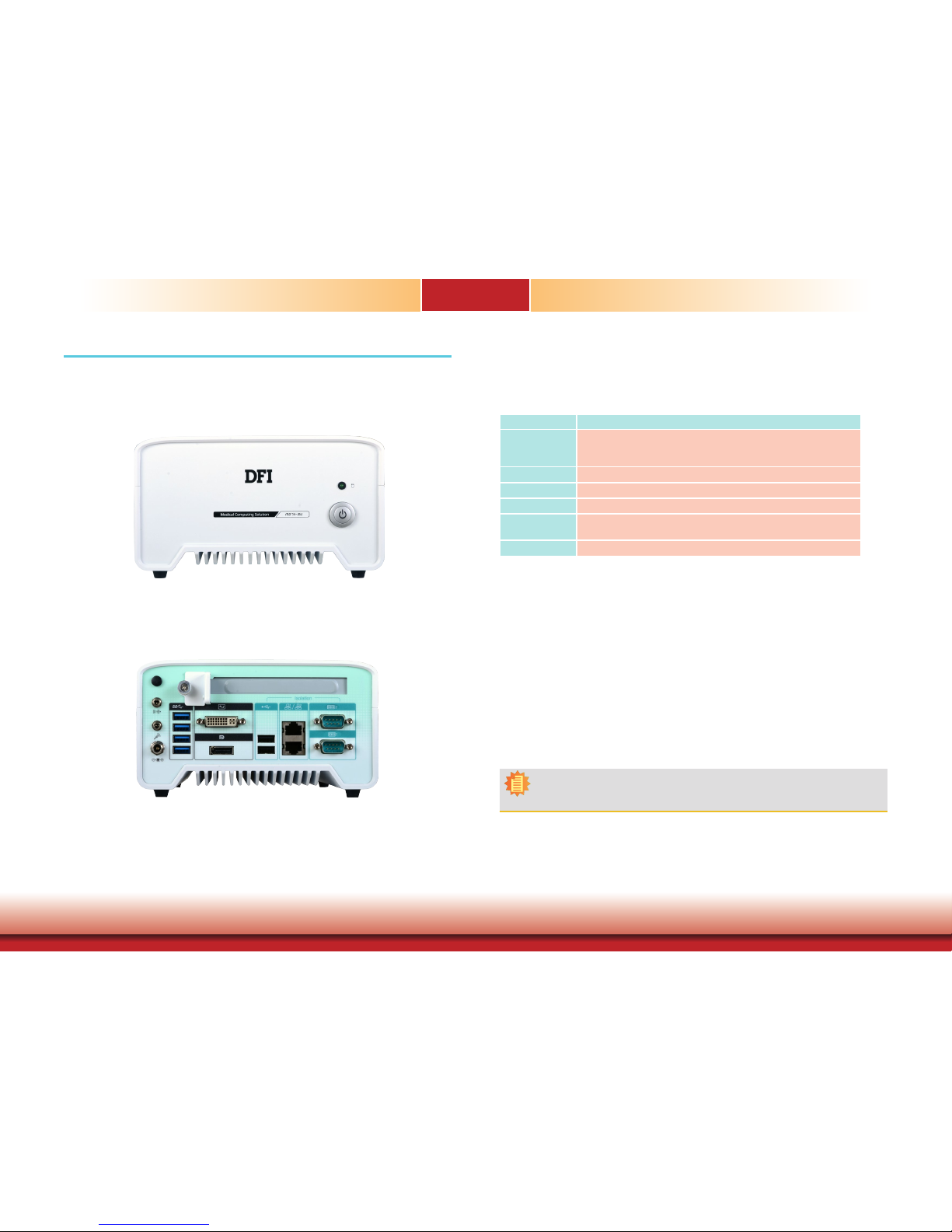
Front View
Rear View
Note:
(*) The USB 2.0, LAN and COM ports provide galvanic isolation up to 3kVac/4kVdc to
prevent damaging circuitry of the electonic devices connected with each other.
Page 9

9
Chapter 1 Introduction
Specications
Chapter 1
Note:
*The mount kit is not supported in standard model. Please contact your sales repre-
sentative for more information.
Vibration • Operating: Random 5~500Hz, IEC68-2-64 (3G) (SSD/mSATA),
IEC68-2-64 (0.5G) (HDD)
• Non-Operating: Sine 10~500Hz, IEC68-2-6 (3G) (SSD/mSATA),
IEC68-2-6 (1G) (HDD)
Shock • Operating: 3G, 11ms
• Non-Operating: 5G, 11ms
Construction
• Aluminum + Metal Aluminum
Mounting
•
Wall mount (*)
Dimensions (W x H x D) • 182mm x 97.6mm x 200mm (7.17" x 3.84" x 7.87")
Weight • TBD
OS Support • Windows 7 (32/64-bit)
• Windows 8.1 (64-bit)
• Windows 10 (64-bit)
• WES 7 (32/64-bit)
• WES 8.1 (64bit)
Certication CE, FCC, RoHS
IEC 60601-1-2:2014
EN 60601-1-2:2015
ISO 14971:2007
Processor System
6th Generation Intel® CoreTM Processors, BGA 1356
Intel® CoreTM i7-6600U Processor, Dual Core, 4M Cache, 2.6GHz, 15W
Intel® CoreTM i5-6300U Processor, Dual Core, 3M Cache, 2.4GHz, 15W
Memory Two 260-pin SODIMM up to 32GB
Dual Channel DDR4 2133MHz
Graphics • Intel® HD Graphics GT Series
• Supported codecs:
OpenGL 5.0, DirectX 12, OpenCL 2.1
HW Decode: AVC/H.264, MPEG2, VC1/WMV9, JPEG/MJPEG,
HEVC/H265, VP8, VP9
HW Encode: AVC/H.264, MPEG2, JPEG, HEVC/H265, VP8, VP9
• Display interfaces:
1 x DP/HDMI (HDMI available upon request)
1 x DVI-D
DP: resolution up to 4096x2304 @ 60Hz
HDMI: resolution up to 2560x1600 @ 60Hz or 4096x2160 @ 24Hz
DVI-D: resolution up to 1920x1200 @ 60Hz
• Supports dual display:
DVI-D + DP
Audio • Supported audio codec: Realtek ALC888 5.1-channel
• Audio jacks: Mic-in and Line-out
Storage/Expansion • 2 x 2.5" SATA 3.0 HDD/SSD with a drive bay
• 1 x PCIe x16 (Gen 3) (x4 lanes)
• Full-size Mini PCIe (PCIe/USB)
• 1 M.2 (2242 key B)
: Supports PCIe, USB and SATA signals
Ethernet 1 x Intel® I210 PCIe (10/100/1000Mbps)
1 x Intel® I219LM with iAMT11.0 PCIe (10/100/1000Mbps)
I/O Ports and LED
Indicators
• Front Panel
- 1 x Power Button
- 1 x Power LED
- 1 x HDD LED
• Rear Panel
- 2 x GbE (RJ-45) (supports 3kVac/4kVdc isolation)
- 2 x RS-232 (DB-9) (supports 3kVac/4kVdc isolation)
- 4 x USB 3.0 (type A)
- 2 x USB 2.0 (type A, full speed; supports 3kVac/4kVdc isolation)
- 1 x DP/HDMI (HDMI available upon request)
- 1 x DVI-D
- 1 x line-out and 1 x microphone jacks
- 1 x antenna hole
Power • 9-36V DC-in
Environment • Temperature
- Operating: 0oC ~ 40oC (w/0.7m air ow)
- Storage: -20oC ~ 85oC
• Relative Humidity
- 5 to 90% RH (non-condensing)
IMPORTANT:
1. The patients should not touch the system.
2. The medical personnel should not touch the system for a long period of time.
3. The system is supposed to connect to a backup power supply such as an uninterruptible power supply (UPS) .
Page 10
10
Chapter 1 Introduction
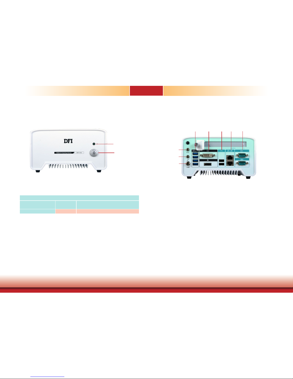
HDD LED (green)
Indicates the status of the storage devices.
Power Button with LED (blue)
Press to power on or off the system.
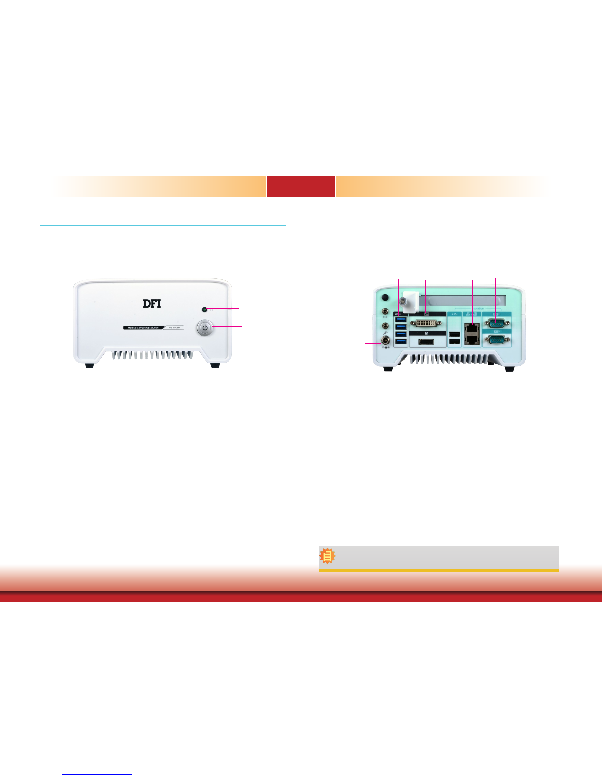
Getting to Know the MD711-SU
Chapter 1
Front View
Rear View
Line-out Port
Connects a speaker.
Mic-in Port
Connects a microphone.
DC-in jack
DC 9-36V power input via a DC-in jack.
DVI-D Port
Connects the DVI-D port of a display device.
DisplayPort (or HDMI, available upon request)
Connects the DP port of a display device.
COM Ports
Connect RS232 serial devices.
USB 3.0 Ports
Connect USB 3.0 devices as well as USB 2.0/1.1 devices.
USB 2.0 Ports (Full Speed)
Connect USB 2.0/1.1 devices. Please note that these USB 2.0 ports can only transmit data at
speeds up to 1.5Mbps (USB 1.0) or 12Mbps (USB 1.1).
LAN Ports
Connect the system to a local area network.
HDD LED
HDD State
Disk access
activity
Disk drives present or not present
LED Behavior
Blink Off
Power Button
with LED (blue)
HDD LED
(green)
DC-in
Mic-in
Line-out
DVI-D
DP
COM 2
COM 1
USB 2.0
LAN 2
LAN 1
USB 3.0
Page 11
11
Chapter 1 Introduction
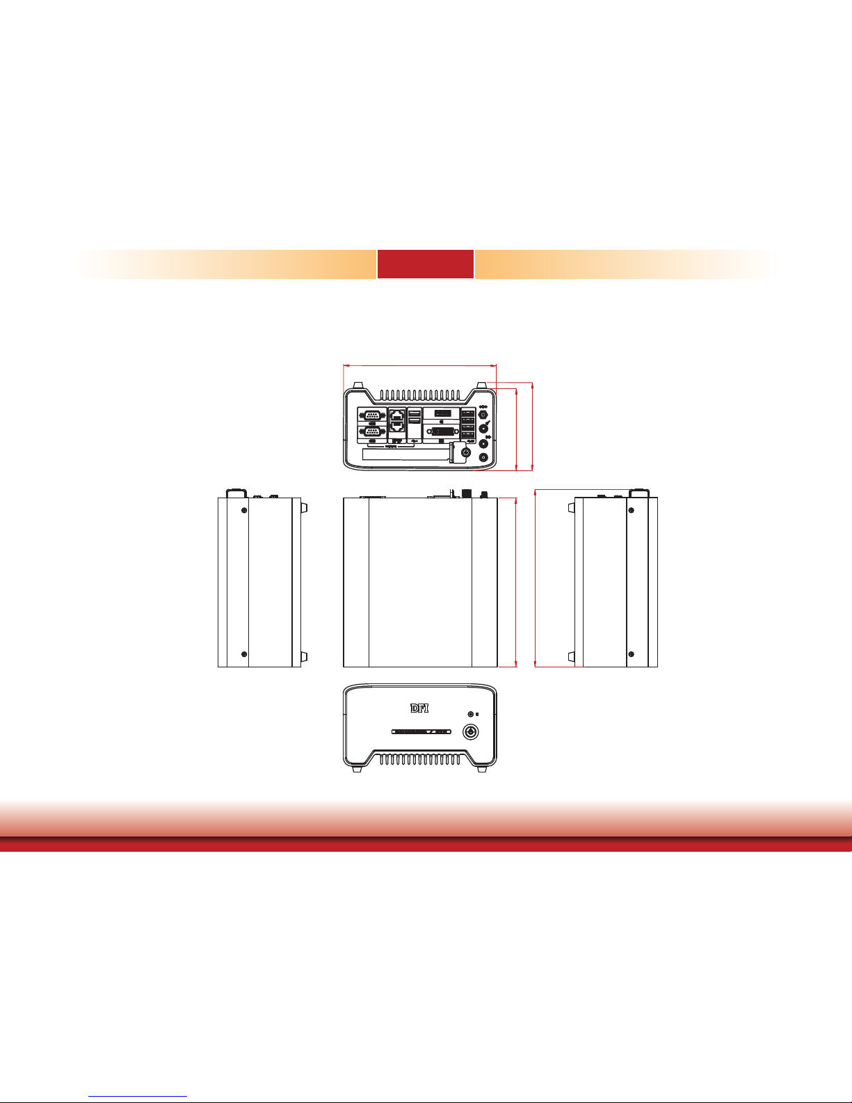
Mechanical Dimensions
Chassis Dimension
Chapter 1
182
97.60
104.80
200
209.80
Rear View
Right View
Top View
Left View
Front View
Page 12

12
Chapter 2 Getting Started
Chapter 2 - Getting Started
Chapter 2
Preparing the System
Before you start using the system, you need the following items:
• AC power adapter or other means of power supply
• DVD-ROM drive (for installing software/drivers)
• Screwdriver
Installing Devices
The following devices can be installed in the system.
• Mini PCIe card
• M.2 modules
• PCIe cards
Configuring the BIOS
To get you started, you may need to change configurations such as the date, time and the
type of hard disk drive.
1. Power on the system.
2. After the memory test, the message “Press DEL to run setup” will appear on the screen.
Press the Delete key to enter the BIOS setup utility.
Installing the Operating System
Most operating system software is prepared using a DVD or bootable USB drive. Please refer
to your operating system manual for instructions on installing an operating system.
Installing the Drivers
The system comes with a software package including drivers. These drivers must be installed
to provide the best system performance. Refer to the Supported Software Chapter for instructions on installing drivers.
Page 13
13
Chapter 3 Installing Devices
Chapter 3
Chapter 3 - Installing Devices
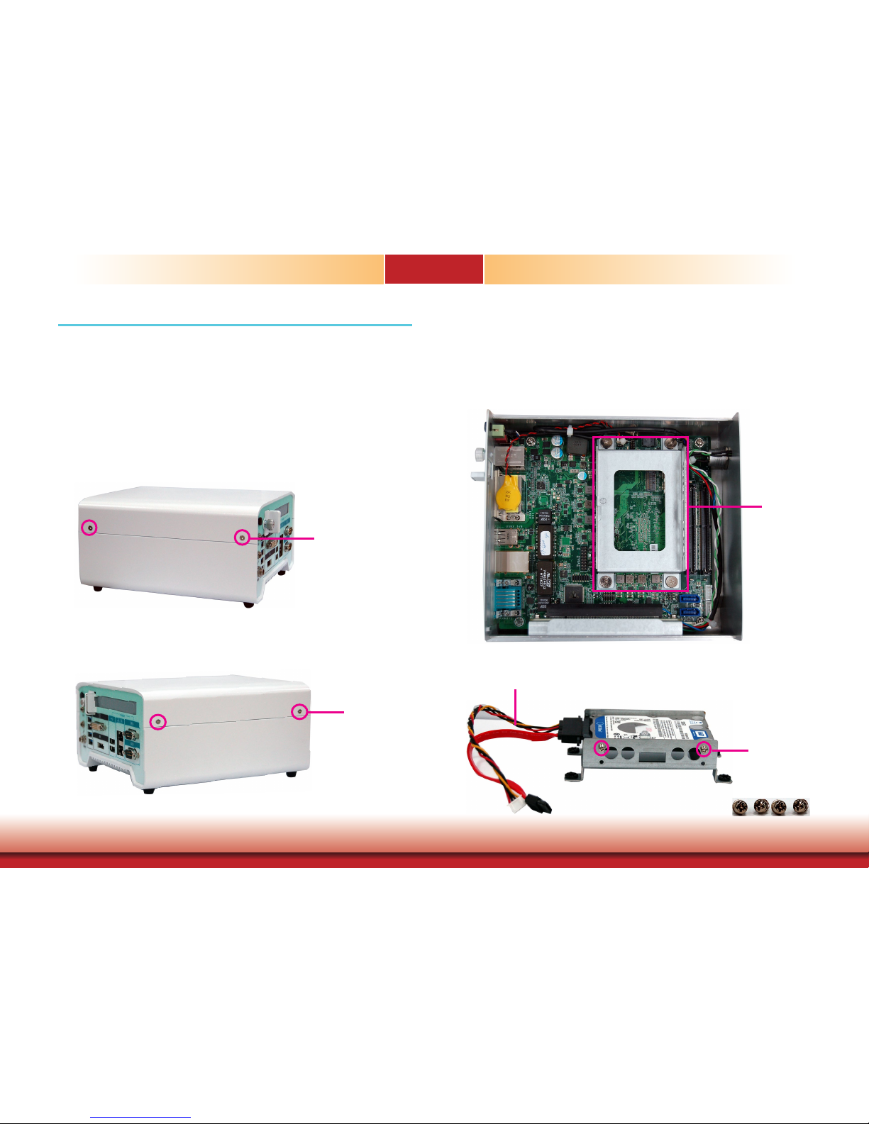
Removing the Chassis Cover
Please observe the following guidelines and follow the procedure to open the system.
1. Make sure the system and all other peripheral devices connected to it have been
powered off.
2. Disconnect all power cords and cables.
3. The 4 screws on the sides of the system are used to secure the cover to the chassis.
Remove these screws and put them in a safe place for later use.
Chassis screw
Chassis screw
Installing a 2.5” SATA Drive
The SATA HDD bracket is included in the product package and can accommodate two
SATA drives.
Use the following procedure to install a SATA HDD or SSD:
HDD bracket
2. Insert the SATA drive into the HDD bracket and secure it in place with the provided screws.
Connect the data and power cables to the drive.
Mounting screw
SATA cables
1. Remove the thumb screws that secure the drive bay on the mainboard and then remove the
drive bay.
Page 14
14
Chapter 3 Installing Devices
Chapter 3
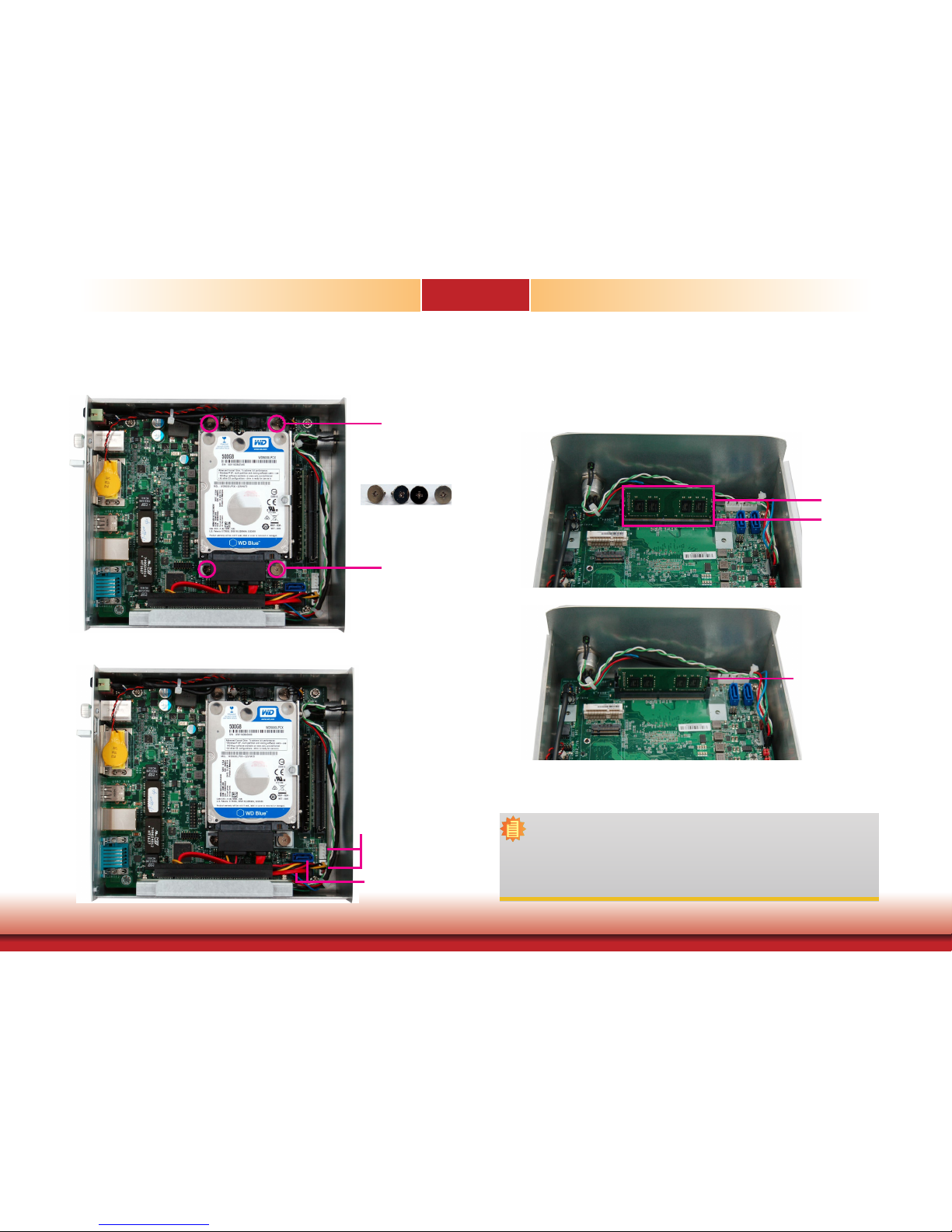
4. Connect the other end of the SATA data cable and the SATA power cable to the SATA data
and SATA power connector on the mainboard respectively.
SATA data connector
SATA power connector
Mounting Screw
Mounting Screw
3. Place the SATA drive with the HDD bracket into the system. Align the mounting holes on
the HDD bracket with the mounting holes on the mainboard and use the provided screws to
secure the drive in place.
Installing a SODIMM
Grasp the module by its edges and align the SODIMM’s notch with the socket’s key; then insert
the SODIMM into the socket at an angle and push it forward until the retaining clips snap
behind. Make sure that you have inserted the module fully into the socket so that the retaining
clips will snap into place.
Insert the SODIMM
at an angle
SODIMM2
SODIMM1
SODIMM is rmly
seated in place with
the
retaining clips
snapped behind
To remove a SODIMM, gently spread the retaining clips at each end of the SODIMM socket. The
SODIMM should pop out of the socket. Lift the SODIMM away from the socket on the mainboard.
Notes:
1. The system supports dual-channel configuration. To enable dual-channel,
populate both SODIMM sockets.
2. If you plan to install only one SODIMM, install it in the DDR4_1 socket (closer
to the center of the mainboard).
3. The SODIMM sockets can only accept DDR4 memory modules. Please do not
install other types of memory modules.
Page 15

15
Chapter 3 Installing Devices
Chapter 3
Installing a Mini PCIe Expansion Card
Insert the card at
an angle
3. Push down on the other end of the Mini PCIe card and secure the card on the mainboard
with the provided mounting screw (same size as the M.2 screw).
Mounting screw
Note:
The Mini PCIe slot provides PCIe and USB signals and can accommodate a Mini
PCIe card.
The Mini PCIe socket is located on the mainboard. Remove the HDD bracket rst to access the
socket. Use the following procedure to install a Mini PCIe card:
1. Grasp the Mini PCIe card by its edges and align the notch in the connector of the Mini PCIe
card with the notch in the connector on the mainboard.
2. Insert the Mini PCIe card into the connector.
Installing an M.2 Expansion Card
The system is equipped with one M.2 socket, supporting the M.2 22x42mm (key B) form
factor. Remove the HDD bracket rst to access the socket. Use the following procedure to
install an M.2 card:
1. Align the notch at the edge of the M.2 card with the key in the connector.
2. Insert the M.2 card into the connector.
Insert the card
at an angle
3. Push down on the other end of the M.2 card and secure and card on the mainboard with the
provided mounting screw (same size as the Mini PCIe screw).
Mounting screw
Note:
The M.2 slot provides PCIe, USB, and SATA signals and can accommodate common
mobile broadband and storage modules.
Page 16
16
Chapter 3 Installing Devices
Chapter 3
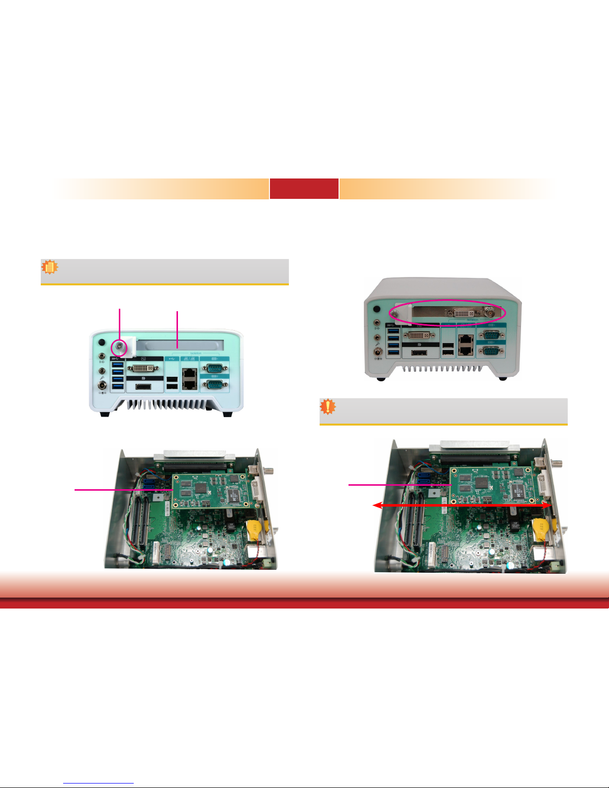
Installing a PCIe Expansion Card
The PCIe slot on the riser card inside the system is used to install expansion cards.
Use the following procedure to install a PCIe expansion card:
Note:
The riser card (DFI model:
T100-1E)
has a x16 PCIe connector (PCIe Gen3 x4 lanes).
1. Remove the slot plate and bracket by removing the thumbscrew on the front chassis.
Slot plate
Mounting screw and bracket
2. Insert the expansion card into the PCIe slot on the riser card. Ensure the card is properly
seated into the slot.
PCIe card
3. secure the bracket in place.
Front View
Important:
When inserting expansion cards into the system, please select a card within
167.65mm (as shown in the picture below) in order to fit into the expansion slot.
PCIe card
167.65mm
Page 17
17
Chapter 4 Jumper Settings
Chapter 4
1
SATA 1
1
SATA 0
SATA 3.0
1
4
Front Panel
Clear CMOS Data
(JP1)
Intel
WGI210AT
1
6
SMBus
DVI-D
DP/HDMI
1
2
11
12
1
4
SATA
Power 0
SATA
Power 1
2
1
13
14
LPC
Standby LED
DDR4_1 SODIMM
DDR4_2 SODIMM
LAN 1 /2
USB 1-4
USB 3.0
USB 5-6
USB 2.0
1
SPI Flash BIOS
USB 2.0 7-8
Auto Power-on
Select (JP4)
Nuvoton
COM 1/2
1
Mic-in
Line-out
PCIe x4
Buzzer
1
2
Battery
9
10
DC-in/Mic-in/Line-out
1
M.2
Mini PCIe
Chapter 4 - Jumper Settings
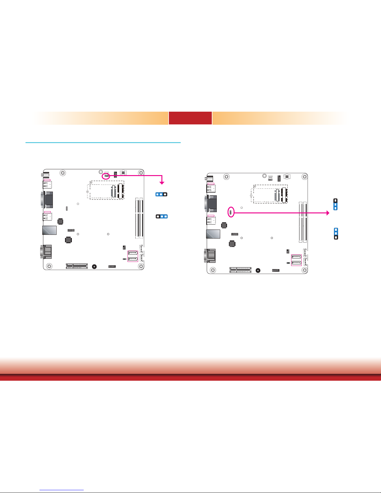
Clear CMOS Data
If you encounter the following situations, you can reconfigure the system with the default values stored in the ROM BIOS.
a) CMOS data becomes corrupted.
b) You forgot the supervisor or user password.
To load the default values stored in the ROM BIOS, please follow the steps below.
1. Power-off the system and unplug the power cord.
2. Set the jumper pins 2 and 3 to On. Wait for a few seconds and set the jumper back to its
default setting, pins 1 and 2 On.
3. Now plug the power cord and power-on the system.
Auto Power-on Select
This jumper is used to select the method of powering on the system. If you want the system
to power on whenever AC power comes in, set the jumper pins 2 and 3 to “On.” If you want
to use the power button, set pins 1 and 2 to “On.”
When using the “Power-On” feature to power the system back on after a power failure occurs,
the system may not power on if the power loss is resumed within 5 seconds (power flicker).
2-3 On:
Power-on via AC power
1-2 On:
Power-on via power button
(default)
1
3
2
1
3
2
JP4
1-2 On:
Normal (default)
1
32
2-3 On:
Clear CMOS Data
1 3
2
1
SATA 1
1
SATA 0
SATA 3.0
1
4
Front Panel
Clear CMOS Data
(JP1)
Intel
WGI210AT
1
6
SMBus
DVI-D
DP/HDMI
1
2
11
12
1
4
SATA
Power 0
SATA
Power 1
2
1
13
14
LPC
Standby LED
DDR4_1 SODIMM
DDR4_2 SODIMM
LAN 1 /2
USB 1-4
USB 3.0
USB 5-6
USB 2.0
1
SPI Flash BIOS
USB 2.0 7-8
Auto Power-on
Select (JP4)
Nuvoton
COM 1/2
1
Mic-in
Line-out
PCIe x4
Buzzer
1
2
Battery
9
10
DC-in/Mic-in/Line-out
1
M.2
Mini PCIe
JP1
Page 18
18
Chapter 5 Ports and Connectors
Chapter 5
Chapter 5 - Ports and Connectors
Front Panel I/O Ports
The front panel I/O consists of the following ports:
• HDD LED (green)
• Power button with LED (blue)
Rear Panel I/O Ports
The rear panel I/O consists of the following ports:
• DC-in power socket
• DVI-D and DP ports (*)
• USB 3.0 ports
• USB 2.0 ports
• COM ports
• LAN ports
• Line-out and Microphone port
Power Button
with LED (blue)
HDD LED
(green)
DC-in
Mic-in
Line-out
DVI-D
DP
COM 2
COM 1
USB 2.0
LAN 2
LAN 1
USB 3.0
Note:
*The system offers another SKU with an HDMI port.
Page 19
19
Chapter 5 Ports and Connectors
Chapter 5
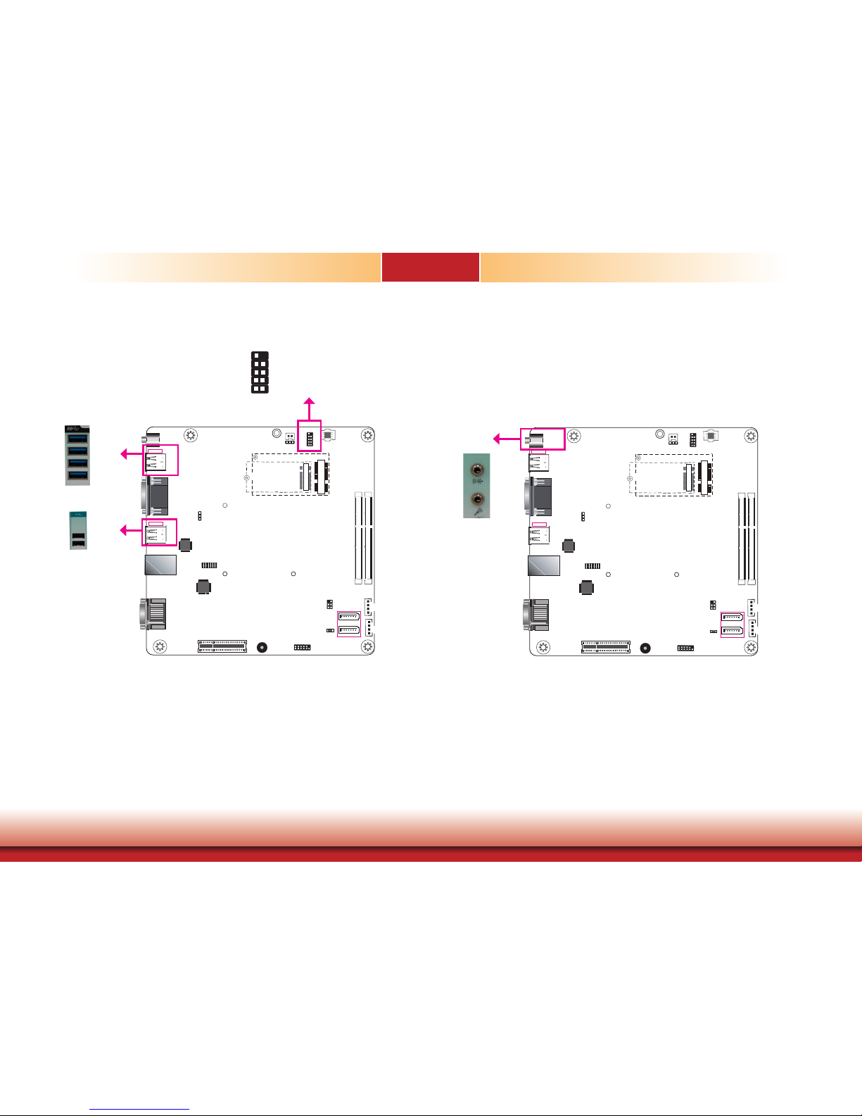
USB Ports
The USB devices allow data exchange between your system and a wide range of simultaneously accessible external Plug and Play peripherals.
The system is equipped with four external USB 3.0 (USB 1-4) and two USB 2.0 (USB 5-6)
ports. The system board also provides two internal USB 2.0 ports (USB 7-8) via pin headers.
Note that these ports can
only
support transmission speeds up to 11Mbps (Full Speed). Please
configure the operating standard using
either
the previous USB 1.1 or USB 1.0 generation on
the rear panel USB 2.0 (USB 5-6) ports in the BIOS menu.
• BIOS Setting
Configure the USB controller in the Advanced menu (“USB Configuration” submenu) of the
BIOS. Refer to Chapter 7 for more information.
Audio Ports
The microphone jack (front panel) and line-out (rear panel) can be connected with an external
microphone and speaker respectively.
• BIOS Setting
Configure the audio controller in the Advanced menu (“Audio Configuration” submenu) of the
BIOS. Refer to Chapter 7 for more information.
• Driver Installation
You may need to install audio driver in your operating system to use audio devices. Refer to
Chapter 8 and your operating system’s documentation for more information.
1
SATA 1
1
SATA 0
SATA 3.0
1
4
Front Panel
Clear CMOS Data
(JP1)
Intel
WGI210AT
1
6
SMBus
DVI-D
DP/HDMI
1
2
11
12
1
4
SATA
Power 0
SATA
Power 1
2
1
13
14
LPC
Standby LED
DDR4_1 SODIMM
DDR4_2 SODIMM
LAN 1 /2
USB 1-4
USB 3.0
USB 5-6
USB 2.0
1
SPI Flash BIOS
USB 2.0 7-8
Auto Power-on
Select (JP4)
Nuvoton
COM 1/2
1
Mic-in
Line-out
PCIe x4
Buzzer
1
2
Battery
9
10
DC-in/Mic-in/Line-out
1
M.2
Mini PCIe
USB 3.0
USB 2.0
USB 2.0
10
VCC
-Data
+Data
GND
VCC
-Data
+Data
GND
N.C.
9
1
2
1
SATA 1
1
SATA 0
SATA 3.0
1
4
Front Panel
Clear CMOS Data
(JP1)
Intel
WGI210AT
1
6
SMBus
DVI-D
DP/HDMI
1
2
11
12
1
4
SATA
Power 0
SATA
Power 1
2
1
13
14
LPC
Standby LED
DDR4_1 SODIMM
DDR4_2 SODIMM
LAN 1 /2
USB 1-4
USB 3.0
USB 5-6
USB 2.0
1
SPI Flash BIOS
USB 2.0 7-8
Auto Power-on
Select (JP4)
Nuvoton
COM 1/2
1
Mic-in
Line-out
PCIe x4
Buzzer
1
2
Battery
9
10
DC-in/Mic-in/Line-out
1
M.2
Mini PCIe
Mic-in
Line-out
Page 20
20
Chapter 5 Ports and Connectors
Chapter 5
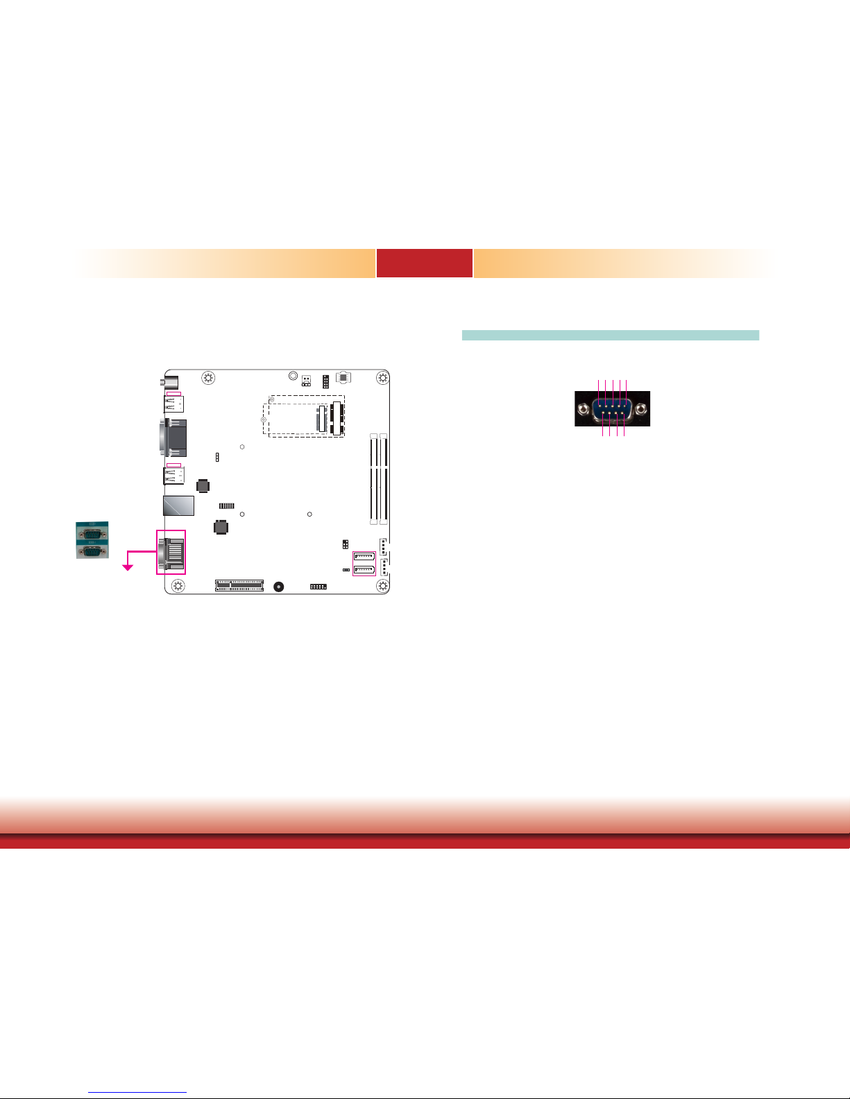
COM Ports
COM 1 to COM 2 (Serial) Ports
COM 1 and COM 2 are RS232 serial ports.
The serial ports are asynchronous communication ports with 16C550A-compatible UARTs that
can be used with modems, serial printers, remote display terminals, and other serial devices.
• BIOS Setting
Congure the COM ports including its communication mode in the Advanced menu (“Super I/O”
submenu) of the BIOS. Refer to Chapter 7 for more information.
1
SATA 1
1
SATA 0
SATA 3.0
1
4
Front Panel
Clear CMOS Data
(JP1)
Intel
WGI210AT
1
6
SMBus
DVI-D
DP/HDMI
1
2
11
12
1
4
SATA
Power 0
SATA
Power 1
2
1
13
14
LPC
Standby LED
DDR4_1 SODIMM
DDR4_2 SODIMM
LAN 1 /2
USB 1-4
USB 3.0
USB 5-6
USB 2.0
1
SPI Flash BIOS
USB 2.0 7-8
Auto Power-on
Select (JP4)
Nuvoton
COM 1/2
1
Mic-in
Line-out
PCIe x4
Buzzer
1
2
Battery
9
10
DC-in/Mic-in/Line-out
1
M.2
Mini PCIe
COM 1 and COM 2: RS232
COM 1 / COM 2
RS232
DCD
1
2 3 4 5
6 7 8 9
TXD
RXD
DTR
GND
RTS
RI
DSR
CTS
Page 21
21
Chapter 5 Ports and Connectors
Chapter 5
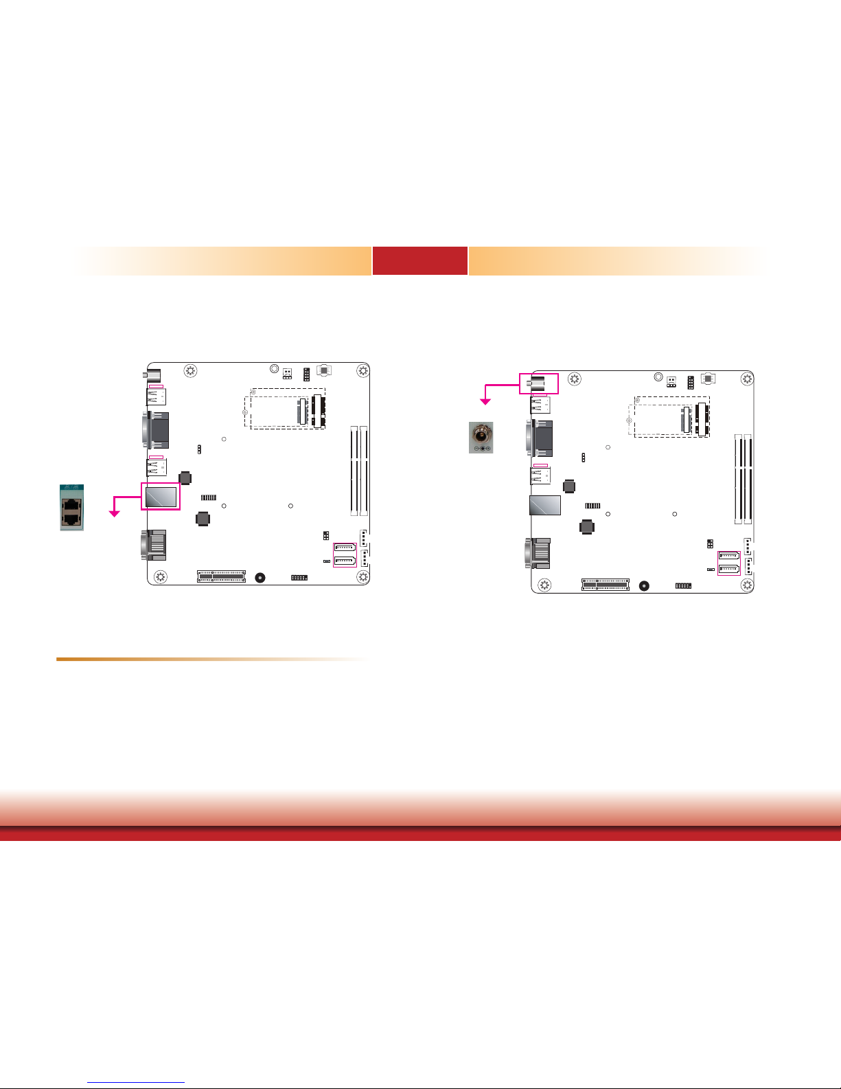
DC-in
Connect a DC power cord of a power adapter with 9-36V DC output voltage. Using a voltage
range out of this specification may fail to boot the system or cause damage to the system
board.
The LAN ports allow the system to connect to a local area network.
BIOS Setting
Configure the onboard LAN in the “Advanced” menu (“ACPI Configuration” submenu) of the
BIOS. Refer to Chapter 7 for more information.
Driver Installation
Install the LAN drivers. Refer to Chapter 8 for more information.
Features
• 2 PCIe Gigabit Ethernet controllers:
LAN 1: Intel® I219LM with iAMT11.0 PCIe (10/100/1000Mbps)
LAN 2: Intel® I210AT PCIe (10/100/1000Mbps)
RJ45 LAN Ports
1
SATA 1
1
SATA 0
SATA 3.0
1
4
Front Panel
Clear CMOS Data
(JP1)
Intel
WGI210AT
1
6
SMBus
DVI-D
DP/HDMI
1
2
11
12
1
4
SATA
Power 0
SATA
Power 1
2
1
13
14
LPC
Standby LED
DDR4_1 SODIMM
DDR4_2 SODIMM
LAN 1 /2
USB 1-4
USB 3.0
USB 5-6
USB 2.0
1
SPI Flash BIOS
USB 2.0 7-8
Auto Power-on
Select (JP4)
Nuvoton
COM 1/2
1
Mic-in
Line-out
PCIe x4
Buzzer
1
2
Battery
9
10
DC-in/Mic-in/Line-out
1
M.2
Mini PCIe
DC-in
1
SATA 1
1
SATA 0
SATA 3.0
1
4
Front Panel
Clear CMOS Data
(JP1)
Intel
WGI210AT
1
6
SMBus
DVI-D
DP/HDMI
1
2
11
12
1
4
SATA
Power 0
SATA
Power 1
2
1
13
14
LPC
Standby LED
DDR4_1 SODIMM
DDR4_2 SODIMM
LAN 1 /2
USB 1-4
USB 3.0
USB 5-6
USB 2.0
1
SPI Flash BIOS
USB 2.0 7-8
Auto Power-on
Select (JP4)
Nuvoton
COM 1/2
1
Mic-in
Line-out
PCIe x4
Buzzer
1
2
Battery
9
10
DC-in/Mic-in/Line-out
1
M.2
Mini PCIe
LAN 2
LAN 1
Page 22
22
Chapter 5 Ports and Connectors
Chapter 5
1
SATA 1
1
SATA 0
SATA 3.0
1
4
Front Panel
Clear CMOS Data
(JP1)
Intel
WGI210AT
1
6
SMBus
DVI-D
DP/HDMI
1
2
11
12
1
4
SATA
Power 0
SATA
Power 1
2
1
13
14
LPC
Standby LED
DDR4_1 SODIMM
DDR4_2 SODIMM
LAN 1 /2
USB 1-4
USB 3.0
USB 5-6
USB 2.0
1
SPI Flash BIOS
USB 2.0 7-8
Auto Power-on
Select (JP4)
Nuvoton
COM 1/2
1
Mic-in
Line-out
PCIe x4
Buzzer
1
2
Battery
9
10
DC-in/Mic-in/Line-out
1
M.2
Mini PCIe
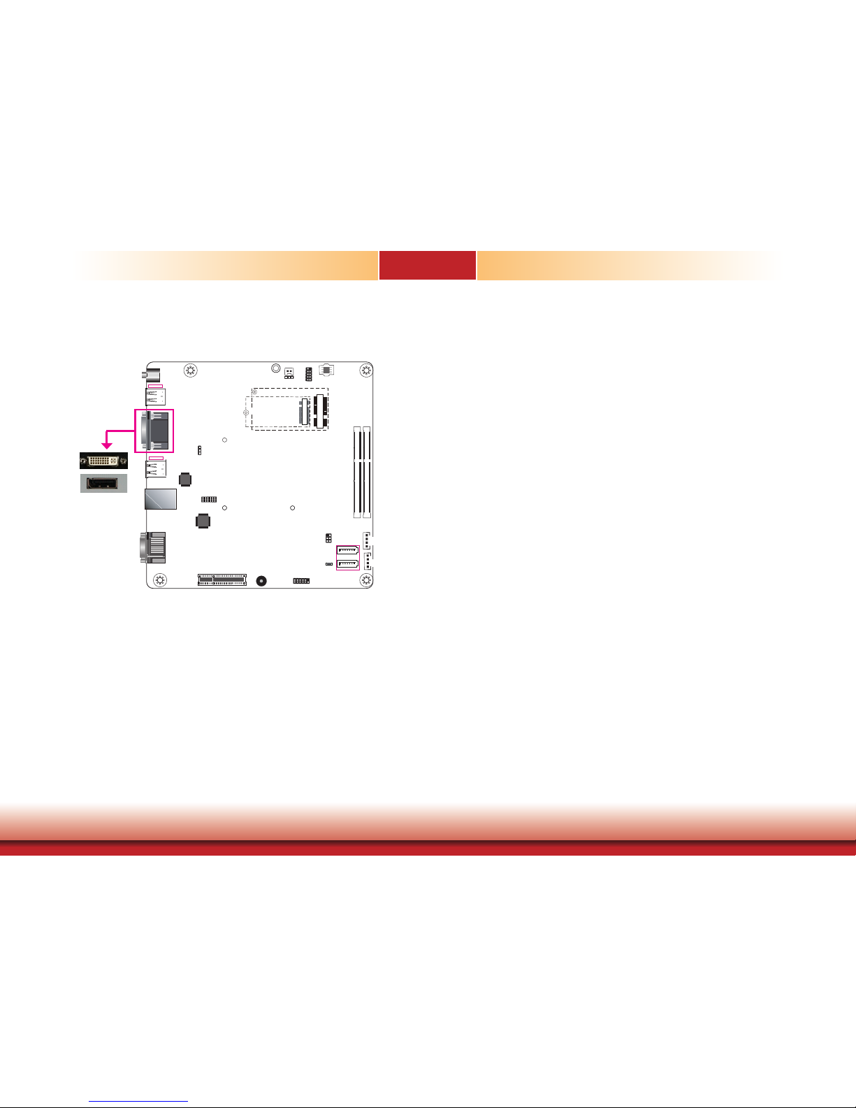
Display Outputs
The DVI-D and DP (DisplayPorts) are used to connect an LCD monitor.
Connect the DVI-D and DP to monitors equipped with a DVI-D and DP port respectively. After
you plug the cable connector into the DVI-D port, gently tighten the cable screws of the DVI-D
cable to secure the connection. The system also supports dual display with these ports.
BIOS Setting
Configure the graphics device in the “Advanced” menu (“Video Configuration” submenu) of the
BIOS. Refer to Chapter 7 for more information.
Driver Installation
Install the graphics driver. Please refer to Chapter 8 for more information.
DP (or HDMI)
Page 23

23
Chapter 5 Ports and Connectors
Chapter 5
1
SATA 1
1
SATA 0
SATA 3.0
1
4
Front Panel
Clear CMOS Data
(JP1)
Intel
WGI210AT
1
6
SMBus
DVI-D
DP/HDMI
1
2
11
12
1
4
SATA
Power 0
SATA
Power 1
2
1
13
14
LPC
Standby LED
DDR4_1 SODIMM
DDR4_2 SODIMM
LAN 1 /2
USB 1-4
USB 3.0
USB 5-6
USB 2.0
1
SPI Flash BIOS
USB 2.0 7-8
Auto Power-on
Select (JP4)
Nuvoton
COM 1/2
1
Mic-in
Line-out
PCIe x4
Buzzer
1
2
Battery
9
10
DC-in/Mic-in/Line-out
1
M.2
Mini PCIe
Expansion slots
I/O Connectors
Mini PCI Express Slot (CN5)
The Mini PCI Express slot on the system board is used to install a full-size Mini PCIe card using PCIe and USB signals.
M.2 Type 2242 Key B (CN6)
The M.2 card slots on the back side of the system board are used to install M.2 (NGFF) modules. The M.2 Type 2242 (B Key) slot can be inserted with either a SATA SSD card or a PCIe
NVMe card with the form factor of M.2 22x42 mm. However, the PCIe Gen 2.0 x2 bandwidth
is capable of up to 1000MB/s transfer speed whereas the SATA 3.0 can only provide up to
600MB/s transfer speed.
PCIe Slot
The PCIe slot provides PCIe Gen3 x4 lanes and can be installed with a riser card with a x16
connector (model:
T100-1E
) to provide expansion capability such as video capture.
The SMBus (System Management Bus) connector is used to connect SMBus devices. It is a
multiple device bus that allows multiple chips to connect to the same bus and enable each one
to act as a master by initiating data transfer.
SMBus Connector
Pins Pin Assignments
1
3V3_SB
2
GND
3
SMB_CLK
4
SMB_DATA
5
SMB_ALERT
6
NC
SMBus (J19)
1
2
5
6
1
SATA 1
1
SATA 0
SATA 3.0
1
4
Front Panel
Clear CMOS Data
(JP1)
Intel
WGI210AT
1
6
SMBus
DVI-D
DP/HDMI
1
2
11
12
1
4
SATA
Power 0
SATA
Power 1
2
1
13
14
LPC
Standby LED
DDR4_1 SODIMM
DDR4_2 SODIMM
LAN 1 /2
USB 1-4
USB 3.0
USB 5-6
USB 2.0
1
SPI Flash BIOS
USB 2.0 7-8
Auto Power-on
Select (JP4)
Nuvoton
COM 1/2
1
Mic-in
Line-out
PCIe x4
Buzzer
1
2
Battery
9
10
DC-in/Mic-in/Line-out
1
M.2
Mini PCIe
Mini PCIe (PCIe/USB)
M.2 Type 2242 (PCIe 2.0 x2/USB/SATA)
PCIe 3.0 x4
Page 24

24
Chapter 5 Ports and Connectors
Chapter 5
Standby LED
Standby Power LED
This LED will blink when the system is in the standby mode. It indicates that there is power
on the system board. Power off the system and then unplug the power cord prior to installing
any devices. Failure to do so will cause severe damage to the motherboard and components.
The lithium ion battery powers the real-time clock and CMOS memory. It is an auxiliary source
of power when the main power is shut off.
Safety Measures
• Danger of explosion if battery incorrectly replaced.
• Replace only with the same or equivalent type recommend by the manufacturer.
• Dispose of used batteries according to local ordinance.
Battery
Battery
Standby Power LED
1
SATA 1
1
SATA 0
SATA 3.0
1
4
Front Panel
Clear CMOS Data
(JP1)
Intel
WGI210AT
1
6
SMBus
DVI-D
DP/HDMI
1
2
11
12
1
4
SATA
Power 0
SATA
Power 1
2
1
13
14
LPC
Standby LED
DDR4_1 SODIMM
DDR4_2 SODIMM
LAN 1 /2
USB 1-4
USB 3.0
USB 5-6
USB 2.0
1
SPI Flash BIOS
USB 2.0 7-8
Auto Power-on
Select (JP4)
Nuvoton
COM 1/2
1
Mic-in
Line-out
PCIe x4
Buzzer
1
2
Battery
9
10
DC-in/Mic-in/Line-out
1
M.2
Mini PCIe
Connect to the battery connector
Battery
1
GND2Battery
1
SATA 1
1
SATA 0
SATA 3.0
1
4
Front Panel
Clear CMOS Data
(JP1)
Intel
WGI210AT
1
6
SMBus
DVI-D
DP/HDMI
1
2
11
12
1
4
SATA
Power 0
SATA
Power 1
2
1
13
14
LPC
Standby LED
DDR4_1 SODIMM
DDR4_2 SODIMM
LAN 1 /2
USB 1-4
USB 3.0
USB 5-6
USB 2.0
1
SPI Flash BIOS
USB 2.0 7-8
Auto Power-on
Select (JP4)
Nuvoton
COM 1/2
1
Mic-in
Line-out
PCIe x4
Buzzer
1
2
Battery
9
10
DC-in/Mic-in/Line-out
1
M.2
Mini PCIe
Page 25

25
Chapter 5 Ports and Connectors
Chapter 5
SATA Data and Power Connector Front Panel Connector
• 2 Serial ATA 3.0 ports with data transfer rate up to 6Gb/s
• Supports Integrated Advanced Host Controller Interface (AHCI) controller and Intel® Rapid
Storage Technology
• Supports RAID 0/1
The Serial ATA connectors are used to connect Serial ATA devices. Connect one end of the Serial ATA data cable to a SATA connector and the other end to your Serial ATA device.
BIOS Setting
Configure the Serial ATA drives in the Advanced menu (“SATA Configuration” submenu) of the
BIOS. Refer to Chapter 7 for more information.
1
SATA 1
1
SATA 0
SATA 3.0
1
4
Front Panel
Clear CMOS Data
(JP1)
Intel
WGI210AT
1
6
SMBus
DVI-D
DP/HDMI
1
2
11
12
1
4
SATA
Power 0
SATA
Power 1
2
1
13
14
LPC
Standby LED
DDR4_1 SODIMM
DDR4_2 SODIMM
LAN 1 /2
USB 1-4
USB 3.0
USB 5-6
USB 2.0
1
SPI Flash BIOS
USB 2.0 7-8
Auto Power-on
Select (JP4)
Nuvoton
COM 1/2
1
Mic-in
Line-out
PCIe x4
Buzzer
1
2
Battery
9
10
DC-in/Mic-in/Line-out
1
M.2
Mini PCIe
RXN
GND
TXP
TXN
GND
RXP
GND
7
1
SATA 0/1
+12V
+5V
Ground
Ground
4
1
SATA
Power 0
SATA
Power 1
1
SATA 1
1
SATA 0
SATA 3.0
1
4
Front Panel
Clear CMOS Data
(JP1)
Intel
WGI210AT
1
6
SMBus
DVI-D
DP/HDMI
1
2
11
12
1
4
SATA
Power 0
SATA
Power 1
2
1
13
14
LPC
Standby LED
DDR4_1 SODIMM
DDR4_2 SODIMM
LAN 1 /2
USB 1-4
USB 3.0
USB 5-6
USB 2.0
1
SPI Flash BIOS
USB 2.0 7-8
Auto Power-on
Select (JP4)
Nuvoton
COM 1/2
1
Mic-in
Line-out
PCIe x4
Buzzer
1
2
Battery
9
10
DC-in/Mic-in/Line-out
1
M.2
Mini PCIe
HDD-LED - HDD LED
This LED will be lit when the hard drive is being accessed.
RESET-SW - Reset Switch
This switch allows you to reboot without having to power off the system.
PWR-LED - Power LED
When the system’s power is on, this LED will light. When the system is in the S1 (POS - Power
On Suspend) state, it will blink every second. When the system is in the S3 (STR - Suspend To
RAM) state, it will blink every 4 seconds.
PWR-BTN - Power Button
This switch is used to power on or off the system.
Front
Panel
2
1
RESET-SW
PWR-LED
PWR-BTN
HDD-LED
11
12
Pin Pin Assignment Pin Pin Assignment
HDD-LED
3 3V3
PWR-LED
2 3V3SB
5 HDD_LED 4 3V3SB
RESET-SW
7 Ground 6 Power_LED
9 RST Signal
PWR-BTN
8 Ground
11 N.C. 10 Power_Button
Page 26

26
Chapter 5 Ports and Connectors
Chapter 5
LPC Connector
The Low Pin Count Interface was dened by Intel® Corporation to facilitate the industry’s transition
towards legacy free systems. It allows the integration of low-bandwidth legacy I/O components
within the system, which are typically provided by a Super I/O controller. Furthermore, it can be
used to interface rmware hubs, Trusted Platform Module (TPM) devices and embedded controller solutions. For more information about LPC bus refer to the Intel® Low Pin Count Interface
Specication Revision 1.1’. The table below indicates the pin assignments of the LPC connector.
LPC Connector
1
SATA 1
1
SATA 0
SATA 3.0
1
4
Front Panel
Clear CMOS Data
(JP1)
Intel
WGI210AT
1
6
SMBus
DVI-D
DP/HDMI
1
2
11
12
1
4
SATA
Power 0
SATA
Power 1
2
1
13
14
LPC
Standby LED
DDR4_1 SODIMM
DDR4_2 SODIMM
LAN 1 /2
USB 1-4
USB 3.0
USB 5-6
USB 2.0
1
SPI Flash BIOS
USB 2.0 7-8
Auto Power-on
Select (JP4)
Nuvoton
COM 1/2
1
Mic-in
Line-out
PCIe x4
Buzzer
1
2
Battery
9
10
DC-in/Mic-in/Line-out
1
M.2
Mini PCIe
Pins Pin Assignment Pins Pin Assignment
1
CLK_24M
2
LAD1
3
RST#
4
LAD0
5
FRAME#
6
VCC3
7
LAD3
8
GND
9
LAD2
10
-
11
SERIRQ
12
GND
13
5VSB
14
5V
1
2
13
14
Page 27

27
Chapter 6 Mounting Options
Chapter 6
Chapter 6 - Mounting Options
Wall Mount
The wall mount kit includes the following:
• Two wall mount brackets
• Bracket screws
Align the mounting holes of the wall mount bracket with the screw holes of the system and use
the provided mounting screws to secure the wall mount brackets on both sides of the system.
103.30
207.60
75 75
10
9 8 7 6 5 4 3 2 1
H
G
F
E
D
C
Sign
Date
Description
Rev.
The following diagrams show the location and dimension of the wall moutning holes.
103.30
207.60
192.60
75 75
Mounting Screw
Take off the rubber feet on the bottom of system using a screw driver.
Page 28

Chapter 7
Chapter 7 BIOS Setup
28
Chapter 7 - BIOS Setup
Overview
The BIOS is a program that takes care of the basic level of communication between the CPU
and peripherals. It contains codes for various advanced features found in this system board.
The BIOS allows you to configure the system and save the configuration in a battery-backed
CMOS so that the data retains even when the power is off. In general, the information stored
in the CMOS RAM of the EEPROM will stay unchanged unless a configuration change has been
made such as a hard drive replaced or a device added.
It is possible that the CMOS battery will fail causing CMOS data loss. If this happens, you need
to install a new CMOS battery and reconfigure the BIOS settings.
Default Configuration
Most of the configuration settings are either predefined according to the Load Optimal Defaults
settings which are stored in the BIOS or are automatically detected and configured without requiring any actions. There are a few settings that you may need to change depending on your
system configuration.
Entering the BIOS Setup Utility
The BIOS Setup Utility can only be operated from the keyboard and all commands are keyboard commands. The commands are available at the right side of each setup screen.
The BIOS Setup Utility does not require an operating system to run. After you power up the
system, the BIOS message appears on the screen and the memory count begins. After the
memory test, the message “Press DEL to run setup” will appear on the screen. If the message
disappears before you respond, restart the system or press the “Reset” button. You may also
restart the system by pressing the <Ctrl> <Alt> and <Del> keys simultaneously.
Note:
The BIOS is constantly updated to improve the performance of the system board;
therefore the BIOS screens in this chapter may not appear the same as the actual
one. These screens are for reference purpose only.
Legends
Scroll Bar
When a scroll bar appears to the right of the setup screen, it indicates that there are more
available fields not shown on the screen. Use the up and down arrow keys to scroll through all
the available fields.
Submenu
When ““ appears on the left of a particular field, it indicates that a submenu which contains
additional options are available for that field. To display the submenu, move the highlight to
that field and press <Enter>.
Keys Function
Right and Left
arrows
Moves the highlight left or right to select a menu.
Up and Down arrows
Moves the hightlight up or down between submenu or elds.
<Esc>
Exit to the BIOS Setup Utility.
+ (plus key)
Scrolls forward through the values or options of the highlighted eld.
- (minus key)
Scrolls backward through the values or options of the highlighted
eld.
<F1>
Displays general help
<F2>
Pervious values
<F3>
Optimized defaults
<F4>
Saves and resets the setup program.
<Enter>
Press <Enter> to enter the highlighted submenu.
Page 29

Chapter 7
Chapter 7 BIOS Setup
29
Main
The Main menu is the first screen that you will see when you enter the BIOS Setup Utility.
Insyde BIOS Setup Utility Advanced
The Advanced menu allows you to configure your system for basic operation. Some entries are
defaults required by the system board, while others, if enabled, will improve the performance
of your system or let you set some features according to your preference.
Important:
Setting incorrect field values may cause the system to malfunction.
System Time
The time format is <hour>, <minute>, <second>. The time is based on the 24-hour
military-time clock. For example, 1 p.m. is 13:00:00. Hour displays hours from 00 to
23. Minute displays minutes from 00 to 59. Second displays seconds from 00 to 59.
System Date
The date format is <month>, <date>, <year>. Month displays the month, from January to December. Date displays the date, from 1 to 31. Year displays the year, from
1980 to 2099.
Page 30

Chapter 7
Chapter 7 BIOS Setup
30
ACPI Configuration
This section configures system ACPI parameters.
Wake on LAN
Enable or disable WOL (wake-on-LAN) to wake the system through an Ethernet adapter.
State After G3
Specify which state the system should be in when power is reapplied after a power failure
(G3, the mechanical-off, state).
S0: The system is powered on (in working state).
S5: The system is powered off (in soft-off state).
CPU Configuration
This section configures the CPU.
Intel® SpeedStep®
Enable or disable the Enhanced Intel® SpeedStep® Technology, which helps optimize
the balance between system’s power consumption and performance. After it is enabled
in the BIOS, you can take advantage of its offering by setting power schemes from the
operating system’s power options.
Turbo Mode
Enable or disable processor turbo mode, which allows the processor core to automatically run faster than the base frequency by taking advantage of thermal and power
headroom.
Page 31

Chapter 7
Chapter 7 BIOS Setup
31
Video Configuration
This section configures the video settings.
Primay Display
Select which graphics device will be the primary display. Note that this option will be
shown only if the “Boot type” is set to “Dual” or “UEFI.”
Internal Graphics
Enable, disable or automatically detect the internal graphics.
Boot display
Prioritize device combination for display during system boot. Note that this option will be
shown only if the “Boot type” is set to “Dual” or “Legacy”.
Audio Configuration
This section configures the audio settings.
Audio Controller
Control the detection of the high-definition audio devices.
Disabled
High-definition audio devices will be unconditionally disabled.
Enabled
High-definition audio devices will be unconditionally enabled.
Auto
High-definition audio devices will be enabled is present and disabled otherwise.
Page 32

Chapter 7
Chapter 7 BIOS Setup
32
SATA Controller
Enable or disable the Serial ATA controller.
SATA Mode Selection
The mode selection determines how the SATA controller(s) operates.
AHCI Mode
This option shows that the Serial ATA devices use AHCI (Advanced Host Controller Interface).
RAID
This option allows you to create RAID using Intel® Rapid Storage Technology (Intel® RST) on
the Serial ATA devices.
Serial ATA Port 0, 1 and 2 and Hot Plug
Enable or disable each Serial ATA port and its hot plug function.
SATA Configuration
This section configures SATA devices. It also shows the information about the installed
SATA drives.
USB Configuration
This section configures the parameters of the USB devices.
USB BIOS Support
Disabled
Disable the USB keyboard/mouse/storage support.
Enabled
Enable the USB keyboard/mouse/storage support.
UEFI Only
Enable the USB keyboard/mouse/storage support only under the UEFI environment.
USB Port 5, 6 Speed Support USB 1.1
Select Enable to set the operating mode to
USB 1.1
on these USB ports 2.0 (USB 5 and 6
on the rear panel). If you would like to use a USB storage device, set it to Enable.
Select Disable to set the operating mode to
USB 1.0
on these USB 2.0 ports. If you would
like to use a USB keyboard/mouse, set it to Disable.
Page 33

Chapter 7
Chapter 7 BIOS Setup
33
PCI Express Configuration
This section configures the settings of PCI Express root ports.
PCIE1
Controls the PCIe expansion slot.
Intel I210
Controls the PCIe signal of the Intel I210 LAN port.
Intel I219
Controls the PCIe signal of the Intel I219LM LAN port.
M.2
Controls the PCIe signal of the M.2 Type 2242 slot.
Mini PCIe
Controls the PCIe signal of the Mini PCIe slot.
Press “Enter” to enter the configurations for each PCIe root port as shown on the right.
PCI Express Root Port
Enable or disable this PCI Express root port.
Hot Plug
Enable or disable the hot plug function.
PCIe Speed
Select the speed of the PCI Express Root Port: Auto, Gen1 (2.5 GT/s), Gen2 (5 GT/s)
or Gen3 (8.0 GT/s).
Page 34

Chapter 7
Chapter 7 BIOS Setup
34
ME Configuration
This section configures flashing of Intel® Active Management Engine region.
Me Fw Image Re-Flash
Enable or disable flashing of the Intel® ME region.
Active Management Technology Support
The section allows users to enable or disable the Intel® Active Management Technology (Intel®
AMT) BIOS extension. Please refer to Chapter 10 - Intel AMT Settings for more information.
Intel® AMT Support
Enable or disable Intel® Active Management Technology BIOS extension.
Un-Configure ME
Clears all ME related configurations without requiring a password on the next boot.
Page 35

Chapter 7
Chapter 7 BIOS Setup
35
COM Port 1 to COM Port 2
Enable or disable each serial port.
Disable Disable this serial port.
Enable Enable this serial port.
It also shows the Base I/O address and the assigned interrupt number.
WDT
Enable or disable the watchdog function. A counter will appear if you select to enable WDT. Input any value between 1 and 255 (seconds).
Super I/O
This section configures the system super I/O chip parameters.
Case Open
Enable or disable the chassis intrusion alert.
AC Power Loss
Set the AC power loss to Always off or Always on. When set to Always off, the system’s
status will be power-off after an AC power loss event. When set to Always on, the
system’s status will be power-on after an AC power loss event.
Page 36

Chapter 7
Chapter 7 BIOS Setup
36
PC Health Status
This section displays PC health status.
Page 37

Chapter 7
Chapter 7 BIOS Setup
37
Security
This section configures the Trusted Platform Module (TPM) function.
TPM Availability
Show or hide TPM availability and its configurations.
TPM Operation
Select one of the supported operation: Enable, Disable, or No Operation.
• No Operation: No changes to the current state.
• Disable: Disable and deactivate TPM.
• Enable: Enable and activate TPM.
Clear TPM
Remove all TPM ownership contents.
Set Supervisor Password
Set the administrative password for entering the BIOS utility or upon the entering of
the power-on self-test (POST) process. The length of the password must be greater
than 1 character and less than or equal to 10 characters.
Power-on Password
If you select to set the supervisor password, this option will be shown. Enable or disable the system to require password at boot.
Page 38

Chapter 7
Chapter 7 BIOS Setup
38
Set All Hdd Password
Set the user password for all HDDs. The length of the password must be greater
than one character and less than or equal to 32 characters.
Set All Master Hdd Password
Set the master password for all HDDs. The length of the password must be greater
than one character and less than or equal to 32 characters.
Storage Password Setup Page
Set the storage password for each detected device. The following configuration options will be shown:
(Device Name)
Select this option to set a password for the selected device.
Security Mode Description
Lock: HDD security status is enabled and locked.
Unlock: HDD security status is enabled and locked.
Change: HDD security status is unlocked and users are allowed to change the password.
Disable: Remove the password from the device.
No Access: HDD Secutiry status is not enabled.
Set Storage Password
Set all HDD password. The length of password must be greater than one character.
Set master HDD password
Set Master Hdd Password. The length of password must be greater than one character
and less than or equal to 32 characters.
Page 39

Chapter 7
Chapter 7 BIOS Setup
39
Boot
NumLock
This allows you to determine the default state of the numeric keypad at boot. By default,
the system boots up with Num Lock on. When set to Off, the function of the numeric
keypad is the arrow keys.
Boot Type
Select the boot type. The options include Dual Boot Type, Legacy Boot Type, and UEFI
Boot Type.
Network Stack
Enable or disable network stack. It supports the operation of these functions or software:
Windows 8 BitLocker Network Unlock and UEFI IPv4/IPv6 PXE or legacy PXE OPROM.
PXE Boot Capability (UEFI mode)/PXE Boot to LAN (legacy mode)
Enable or disable Preboot eXecution Environment (PXE) boot through an Ethernet port.
This function can only be enabled if the Network Stack support is enabled under the UEFI
Boot Type.
USB Boot
Enable or disable USB boot from a flash drive.
EFI
Enter this menu to select the priority of the UEFI boot devices. Use the “+” key to move
an item up or the “-” key to move an item down. The one on the top of the list has the
highest priority.
Note:
If the boot type is set to UEFI, the method for RAID volume creation will be
different. Please refer to Chapter 9 - RAID for more information.
Boot Menu
This section configures legacy boot order. This menu is shown only when the boot type
is set to “Legacy” or “Dual”.
Normal
For this option, determine the boot order for the devices within each category. Use +
and - keys to arrange the priority of the boot devices in the list. The first device in the
list has the highest boot priority.
Advance
For this option, determine the boot order for all bootable devices. Use + and - keys to
arrange the priority of the detected boot devices in the list. The first device in the list
has the highest boot priority.
Boot Device Priority
Page 40

Chapter 7
Chapter 7 BIOS Setup
40
Exit
Exit Saving Changes
Select this field and press <Enter> to exit BIOS setup and save your changes.
Load Optimal Defaults
Select this field and press <Enter> to load the optimal defaults.
Discard Changes
Select this field and press <Enter>to exit the BIOS setup without saving your changes.
Page 41

Chapter 7
Chapter 7 BIOS Setup
41
Updating the BIOS
To update the BIOS, you will need the new BIOS file and a flash utility. Please contact technical support or your sales representative for the files and specific instructions about how to
update BIOS with the flash utility.
When you download the given BIOS file, you may find a BIOS flash utility attached with the
BIOS file. This is the utility for performing BIOS updating procedure. For your convenience, we
will also provide you with an auto-execution file in the BIOS file downloaded. This auto-execution file will bring you directly to the flash utility menu soon after system boots up and finishes
running the boot files in your boot disk.
|
|
|
|
Notice: BIOS SPI ROM
1. The Intel® Management Engine has already been integrated into this system board. Due to
safety concerns, the BIOS (SPI ROM) chip cannot be removed from this system board and
used on another system board of the same model.
2. The BIOS (SPI ROM) on this system board must be the original equipment from the factory
and cannot be used to replace one which has been utilized on other system boards.
3. If you do not follow the methods above, the Intel® Management Engine will not be
updated and will cease to be effective.
Note:
a. You can take advantage of flash tools to update the default configuration of the
BIOS (SPI ROM) to the latest version anytime.
b. When the BIOS IC needs to be replaced, you have to populate it properly onto the
system board after the EEPROM programmer has been burned and follow the
technical person's instructions to confirm that the MAC address should be burned
or not.
R
Read le successfully. (path= “platform.ini”)
Insyde H20FFT (Flash Firmware Tool) Version (SEG) 100.00.08.10
Copyright(c) 2012 - 2016, Insyde Software Corp. All Rights Reserved.
Initializing
Current BIOS Model name: SU273
New BIOS Model name: SU273
Current BIOS version: 68.08A
New BIOS version: 68.08A
Updating Block at FFFFF000h
0% 25% 50% 75% 100%
100%
C:\SU25x>_
Information
Please do not remove the AC power
Page 42

Chapter 8
www.d.com
42
Chapter 8 Supported Software
Chapter 8 - Supported Software
The system requires you to install drivers for some devices to operate properly. To download
the latest driver, please go to the DFI Download Center:
http://www.dfi.com/DownloadCenter
Once you are in the Download Center page, select your product or type the model name and
click "Search" to nd product-related resources such as documentation and drivers.
Drivers are available for the following devices in Windows 7, 8.1 and 10:
• Intel® Chipset Device Software
• Intel® Graphics Driver
• Intel® Rapid Storage Technology
• Intel® LAN Driver
• Kernel Mode Driver Framework (For Windows 7 only)
• Intel® ME Driver
• Intel® USB 3.0 Driver (For Windows 7 and Windows 8.1)
• Audio Driver
• Intel® Serial IO Driver
Intel Chipset Device Software
The Intel Chipset Device Software is used for updating Windows® INF files so that the Intel
chipset can be recognized and configured properly in the system.
To install this driver, follow these steps:
1. Setup is ready to install
the utility. Click “Next” to
continue.
2. Read the license agreement
and then click “Yes”.
Page 43

Chapter 8
www.d.com
43
Chapter 8 Supported Software
3. Go through the readme document for more installation tips
and then click “Next”.
4. Click “Finish” to exit setup.
Intel Rapid Storage Technology
The Intel Rapid Storage Technology is a utility that allows you to monitor the current status of
the SATA drives. It also enables enhanced performance and power management for the storage subsystem.
To install this driver, follow these steps:
1. The setup program is preparing
to install the driver. Please exit
all programs before continuing
with the installation.
2. Read the license agreement
carefully, accept the terms of the
License Agreement, then click
“Next” to continue.
Page 44

Chapter 8
www.d.com
44
Chapter 8 Supported Software
Intel Graphics Driver
To install this driver, follow these steps:
1. Setup is now ready to
install the graphics driver.
Click “Next”.
By default, the “Automatically run WinSAT and enable the Windows Aero
desktop theme” is enabled. With this enabled, after installing the graphics
driver and the system rebooted, the screen will turn blank for 1 to 2 minutes
(while WinSAT is running) before the Windows 7/Windows 8.1/Windows 10
desktop appears. The “blank screen” period is the time Windows is testing
the graphics performance.
2. Read the license agree-
ment, and then click “Yes”.
3. Read the readme information and
then click “Next.”
4. Setup is currently installing the
driver. Click “Next” to install to
the default folder or select to
change the installation folder.
The setup will then inform you
that the Intel® Rapid Storage
Technology will be installed on
your system.
5. Click “Yes, I want to restart
this computer now”, then
click “Finish.”
Restarting the system will
allow the new software
installation to take effect.
Page 45

Chapter 8
www.d.com
45
Chapter 8 Supported Software
4. Setup is now installing
the driver. Click “Next” to
continue.
3. Go through the readme
document for system requirements and installation
tips, and then click “Next”.
5. Click “Yes, I want to restart
this computer now”, and
then click “Finish”.
Restarting the system will
allow the new software
installation to take effect.
Audio Drivers
To install this driver, follow these steps:
2. Click “Yes, I want to restart
my computer now”, and
then click “Finish”.
Restarting the system will
allow the new software
installation to take effect.
1. Setup is ready to install
the driver. Click “Next” to
continue.
Page 46

Chapter 8
www.d.com
46
Chapter 8 Supported Software
Intel LAN Drivers
To install this driver, follow these steps:
1. Setup is ready to install
the driver. Click “Next” to
continue.
2. Click “I accept the terms in
the license agreement”, and
then click “Next”.
3. Select the program features
you want installed, and
then click “Next”.
4. Click “Install” to begin the
installation.
5. After the installation is
complete, click “Finish”.
Page 47

Chapter 8
www.d.com
47
Chapter 8 Supported Software
Kernel Mode Driver (For Windows 7 only)
To install this driver, follow these steps:
1. Click “Yes“ to install the
update.
2. The update is being
installed now.
3. Click “Restart Now“ to
restart your computer when
the installation is complete.
Page 48

Chapter 8
www.d.com
48
Chapter 8 Supported Software
Intel Management Engine Drivers
To install this driver, follow these steps:
1. Setup is ready to install
the driver. Click “Next” to
continue.
2. Read the license agreement, and then click “Next”.
3. Setup is currently installing
the driver. After the installation is complete, click
“Next”.
4. Please wait while the product is being installed.
5. After the installation is
complete, click “Finish”.
Page 49

Chapter 8
www.d.com
49
Chapter 8 Supported Software
Intel USB 3.0 Driver (For Windows 7 and Windows 8.1)
To install this driver, follow these steps:
2. Read the license agreement, and
then click “Yes”.
1. Setup is ready to install the driver.
Click “Next” to continue.
3. Go through the readme document for more installation tips,
and then click “Next”.
4. Setup is currently installing the
driver. After the installation is
complete, click “Next”.
5. After the installation is complete,
click “Finish”.
Page 50

Chapter 8
www.d.com
50
Chapter 8 Supported Software
IO Driver
To install this driver, follow these steps:
1. Setup is ready to install the driver.
Click “Next”.
2. Read the license agreement carefully. Click “I accept the terms in
the License Agreement”, and then
click “Next”.
4. Setup is ready to install the driver.
Click “Next” to continue.
3. Read the file information, and then
click “Next”.
Page 51

Chapter 8
www.d.com
51
Chapter 8 Supported Software
5. Setup is now installing the
driver.
6. Click “Finish” to exit the
setup.
Page 52

Chapter 8
www.d.com
52
Chapter 8 Supported Software
Microsoft Framework 4.5.2 (For Windows 7 only)
To install this driver, follow these steps:
1. Setup is now extracting files.
Note:
Before installing Microsoft Framework 4.5.2, make sure you have updated your
Windows 7 operating system to Service Pack 1 or above.
2. Read the license agreement carefully.
Click “I have read and accept
the terms of the License Agree
ment”, and then click “Install”.
3. Setup is now installing the
driver.
4. Click “Finish” to exit the
setup program.
Page 53

Chapter 8
www.d.com
53
Chapter 8 Supported Software
Infineon TPM 1.2 Driver and Tool (Optional)
To install this driver, follow these steps:
1. The setup program is preparing
to install the driver.
2. The setup program is now ready
to install the utility. Click “Next”
to continue.
3. Click “I accept the terms in the
license agreement”, and then
click “Next”.
4. Enter the necessary information,
and then click “Next”.
5. Select a setup type, and then click
“Next”.
6. Click “Install” to begin the
installation.
Page 54

Chapter 8
www.d.com
54
Chapter 8 Supported Software
7. TPM requires installing the Microsoft Visual C++ package prior to
installing the utility. Click “Install”
to start the installation.
8. The setup program is currently
installing the Microsoft Visual
C++ package.
9. Click “Finish”.
10. Click “Yes” to restart your system.
Page 55

Chapter 8
www.d.com
55
Chapter 8 Supported Software
Adobe Acrobat Reader 9.3
To install this driver, follow these steps:
1. Click “Next” to install or
click “Change Destination
Folder” to select a different
folder for installation.
2. Click “Install” to begin installing the program.
3. Click “Finish” to exit the installation.
Page 56

56
Chapter 5 RAID
Chapter 5Chapter 9
www.d.com
Chapter 9 RAID
Chapter 9 - RAID
Settings
To enable the RAID function, the following settings are required.
1. Connect the Serial ATA drives.
2. Enable Serial ATA in the Insyde BIOS.
3. Create a RAID volume.
3-1. Create a RAID volume if the boot type is UEFI.
4. Install the Intel Rapid Storage Technology Utility.
Step 1: Connect the Serial ATA Drives
Refer to Chapter 3 for details on connecting the Serial ATA drives.
Important:
1. Make sure you have installed the Serial ATA drives and connected the data cables
otherwise you won’t be able to enter the RAID BIOS utility.
2. Treat the cables with extreme caution especially while creating RAID. A damaged
cable will ruin the entire installation process and operating system. The system will
not boot and you will lost all data in the hard drives. Please give special attention
to this warning because there is no way of recovering back the data.
Step 2: Enable RAID in the BIOS
1. Power-on the system then press <Del> to enter the main menu of the BIOS setup utility.
2. Go to “Advanced” menu, and select the “SATA Configuration” menu.
3. Change the “SATA Mode Selection” to “RAID” mode.
4. Save the changes in the “Save & Exit” menu.
5. Reboot the system.
The system board allows configuring RAID on Serial ATA drives. It supports RAID 0 and
RAID 1.
RAID Levels
RAID 0 (Striped Disk Array without Fault Tolerance)
RAID 0 uses two new identical hard disk drives to read and write data in parallel, interleaved stacks. Data is divided into stripes and each stripe is written alternately between
two disk drives. This improves the I/O performance of the drives at different channel;
however it is not fault tolerant. A failed disk will result in data loss in the disk array.
RAID 1 (Mirrored Disk Array with Fault Tolerance)
RAID 1 copies and maintains an identical image of the data from one drive to the other
drive. If a drive fails to function, the disk array management software directs all applications to the other drive since it contains a complete copy of the drive’s data. This enhances
data protection and increases fault tolerance to the entire system. Use two new drives or
an existing drive and a new drive but the size of the new drive must be the same or larger
than the existing drive.
RAID Level Min. Drives Protection Description
RAID 0 2 None Data striping without redundancy
RAID 1 2 Single Drive Failure Disk mirroring
Page 57

57
Chapter 5 RAID
Chapter 5Chapter 9
www.d.com
Chapter 9 RAID
Step 3: Create a RAID Volume
1. When the Intel® RST option ROM status screen displays during POST, press <Ctrl> and
<I> simultaneously to enter the option ROM user interface.
2. Select 1: Create RAID Volume and press <Enter>.
3. Use the up or down arrow keys to select the RAID level and press <Enter>.
4. Use the up or down arrow keys to select the strip size and press <Enter>.
5. Press <Enter> to select the physical disks.
6. Use the up or down arrow keys to scroll through the list of hard drives and press <Space>
to select the drive.
7. Press <Enter>.
8. Select the volume size and press <Enter>. You must select less than one hundred percent
of the available volume space to leave space for the second volume.
9. Press <Enter> to create the volume.
10. At the prompt, press <Y> to confirm volume creation.
11. Select 4: Exit and press <Enter>.
12. Press <Y> to confirm exit.
Note:
These steps are cited from the Intel® Support site, “Set Up a System with Intel®
Matrix RAID Technology” (Article ID: 000005789).
http://www.intel.com/content/www/us/en/support/boards-and-kits/000005789.html
Step 3-1: Create a RAID Volume if the Boot Type is UEFI
If the boot type is set to UEFI, RAID volume creation will be different. Please use the following steps
to create RAID volumes. To set the boot type, enter the Insyde BIOS and go to “Boot” >”Boot type”.
1. Go to the “Advanced” menu of the Insyde BIOS.
2. The “Intel® Rapid Storage Technology” menu appears. Enter this menu.
3. The screen displays all available drives. Select “Create RAID volume” to create a RAID volume”.
4. Use the up or down arrow keys to select the RAID level and press <Enter>.
5. Use the up or down arrow keys to scroll through the list of hard drives and press <Space> to
select the drive.
6. Press <Enter>.
7. Use the up or down arrow keys to select the strip size and press <Enter>.
8. Enter the volume size and press <Enter>.
9. At the prompt, press <Y> to confirm volume creation.
Page 58

58
Chapter 5 RAID
Chapter 5Chapter 9
www.d.com
Chapter 9 RAID
Step 4: Install the Intel Rapid Storage Technology Utility
The Intel Rapid Storage Technology Utility can be installed from within Windows. It allows
RAID volume management (create, delete, migrate) from within the operating system. It will
also display useful SATA device and RAID volume information. The user interface, tray icon
service and monitor service allow you to monitor the current status of the RAID volume and/
or SATA drives. It enables enhanced performance and power management for the storage
subsystem.
1. Insert the provided DVD into an optical drive.
2. Click “Intel Rapid Storage Technology Utility” on the main menu.
4. Read the license agreement and click “I accept
the terms in the License
Agreement.“ Then, click
Next.
3. Setup is ready to install
the utility. Click Next.
5. Go through the readme
document to view system
requirements and installation information then click
Next.
7. Confirm the installation and
click Next.
6. Click Next to install to
the default folder or click
change to choose another
destination folder.
Page 59

59
Chapter 5 RAID
Chapter 5Chapter 9
www.d.com
Chapter 9 RAID
8. Click “Yes, I want to restart
this computer now” to
complete the installation
and then click Finish.
Page 60

www.d.com
60
Chapter 10 Intel AMT Settings
Chapter 6
Chapter 10
Chapter 10 - Intel AMT Settings
Overview
Intel Active Management Technology (Intel® AMT) combines hardware and software solutions
to provide maximum system defense and protection to networked systems.
The hardware and software information are stored in non-volatile memory. With its built-in
manageability and the latest security applications, Intel® AMT provides the following functions.
• Discover
Allows remote access and management of networked systems even while PCs are powered off;
significantly reducing desk-side visits.
• Repair
Remotely repair systems after OS failures. Alerting and event logging help detect problems
quickly to reduce downtime.
• Protect
Intel AMT’s System Defense capability remotely updates all systems with the latest security
software. It protects the network from threats at the source by proactively blocking incoming
threats, reactively containing infected clients before they impact the network, and proactively
alerting when critical software agents are removed.
Enable Intel® AMT in the BIOS
1. Power on the system then press <Del> to enter the main menu of the BIOS setup utility.
2. In the “Advanced” menu, select “Active Management Technology Support”.
3. In the “Active Management Technology Support” menu, select “Enabled” for “Intel AMT
Support”.
Page 61

www.d.com
61
Chapter 10 Intel AMT Settings
Chapter 6
Chapter 10
4. In the “Exit” menu, select “Exit Saving Changes” and then select “OK”.
Set up Intel® AMT using the Intel® Management
Engine BIOS Extension (MEBX)
1. After the system reboots, press <Del> to enter the BIOS menu again.
2. In the “Advanced” menu, select “MEBX Configuration” to enter the Manageability Engine
BIOS Extension (MEBx) Setup.
3. When the system reboots, you will be prompted for a password. The default password is
“admin”. Enter the default password in the space provided under Intel(R) ME Password,
then press “Enter”.
MAIN MENU
MEBx Login
> Intel (R) ME General Settings
> Intel (R) AMT Conguration
MEBx Exit
Intel(R) ME Password
[↑↓] = Move Highlight [Enter] = Select Entry [Esc]= Exit
Intel(R) Management Engine BIOS Extension v11.0.0.0008/Intel(R) ME v11.8.50.3399
Copyright(C) 2003-16 Intel Corporation. Al l Righ ts Reserve d
Page 62

www.d.com
62
Chapter 10 Intel AMT Settings
Chapter 6
Chapter 10
MAIN MENU
MEBx Login
> Intel (R) ME General Settings
> Intel (R) AMT Conguration
MEBx Exit
Intel(R) ME Password
[↑↓] = Move Highlight [Enter] = Select Entry [Esc]= Exit
Intel (R) ME Password
4. Enter a password in the space provided under “Intel(R) ME Password” and then press
“Enter”. The password must include:
• 8-32 characters
• Strong 7-bit ASCII characters excluding : , and ” characters
• At least one digit character (0, 1, ...9)
• At least one 7-bit ASCII non alpha-numeric character, above 0x20, (e.g. !, $, ;)
• Both lower case and upper case characters
5. You will be asked to verify the password. Enter the same new password in the space provided under “Verify Password” and then press “Enter”.
6. Select “Intel(R) ME General Settings” and then press “Enter”.
Intel(R) Management Engine BIOS Extension v11.0.0.0008/Intel(R) ME v11.8.50.3399
Copyright(C) 2003-16 Intel Corporation. Al l Righ ts Reserve d
MAIN MENU
MEBx Login
> Intel (R) ME General Settings
> Intel (R) AMT Conguration
MEBx Exit
Intel(R) ME Password
[↑↓] = Move Highlight [Enter] = Select Entry [Esc]= Exit
Verify Password
Intel(R) Management Engine BIOS Extension v11.0.0.0008/Intel(R) ME v11.8.50.3399
Copyright(C) 2003-16 Intel Corporation. Al l Righ ts Reserve d
MAIN MENU
> Intel (R) ME General Settings
> Intel (R) AMT Conguration
MEBx Exit
[↑↓] = Move Highlight [Enter] = Select Entry [Esc]= Exit
Intel(R) Management Engine BIOS Extension v11.0.0.0008/Intel(R) ME v11.8.50.3399
Copyright(C) 2003-16 Intel Corporation. Al l Righ ts Reserve d
Page 63

www.d.com
63
Chapter 10 Intel AMT Settings
Chapter 6
Chapter 10
INTEL (R) ME PLATFORM CONFIGURATION
Change ME Password
Local FW Update <Enabled>
Intel (R) ME New Password
[↑↓] = Move Highlight [Enter] = Select Entry [Esc]= Exit
7. Select “Change Intel(R) ME Password” and then press “Enter”.
You will be prompted for a password. The default password is “admin”. Enter the default
password in the space provided under “Intel(R) ME New Password” and then press “Enter”.
• 8-32 characters
• Strong 7-bit ASCII characters excluding : , and ” characters
• At least one digit character (0, 1, ...9)
• At least one 7-bit ASCII non alpha-numeric character, above 0x20, (e.g. !, $, ;)
• Both lower case and upper case characters
8. Select “Local FW Update” and then press “Enter”. Select “Enabled” or “Disabled” or
“Password Protected” and then press “Enter”.
9. Select Previous Menu until you return to the “Main Menu”. Select “Intel(R) AMT Configuration” and then press “Enter”.
Intel(R) Management Engine BIOS Extension v11.0.0.0008/Intel(R) ME v11.8.50.3399
Copyright(C) 2003-16 Intel Corporation. Al l Righ ts Reserve d
Change ME Password
Local FW Update <Enabled>
[↑↓] = Move Highlight [Enter] = Complete Entry [Esc]= Discard Changes
Disabled
Enabled
Password Protected
INTEL (R) ME PLATFORM CONFIGURATION
Intel(R) Management Engine BIOS Extension v11.0.0.0008/Intel(R) ME v11.8.50.3399
Copyright(C) 2003-16 Intel Corporation. Al l Righ ts Reserve d
INTEL (R) AMT CONFIGURATION
[↑↓] = Move Highlight [Enter] = Select Entry [Esc]= Exit
Manageability Feature Selection < Enabled>
> SOL/Storage Redirection/KVM
> User Consent
Password Policy <Anytime>
> Network Setup
Activate Network Access
Uncongure Network Access <Full Unprovision>
> Remote Setup And Conguration
> Power Control
Intel(R) Management Engine BIOS Extension v11.0.0.0008/Intel(R) ME v11.8.50.3399
Copyright(C) 2003-16 Intel Corporation. Al l Righ ts Reserve d
Page 64

www.d.com
64
Chapter 10 Intel AMT Settings
Chapter 6
Chapter 10
10. In the “Intel(R) AMT Configuration” menu, select “Manageability Feature Selection” and
then press “Enter”. Select “Enabled” or “Disabled” and then press “Enter”.
11. In the “Intel(R) AMT Configuration” menu, select “SOL/Storage Redirection/KVM” and
then press “Enter”.
12. In the “SOL/Storage Redirection/KVM” menu, select “Username and Password” and then
press “Enter”. Select “Enabled” or “Disabled” and then press “Enter”.
13. In the “SOL/Storage Redirection/KVM” menu, select “SOL” and then press “Enter”. Select
“Enabled” or “Disabled” and then press “Enter”.
Manageability Feature Selection < Enabled>
> SOL/Storage Redirection/KVM
> User Consent
Password Policy <Anytime>
> Network Setup
Activate Network Access
Uncongure Network Access <Full Unprovision>
> Remote Setup And Conguration
> Power Control
Disabled
Enabled
INTEL (R) AMT CONFIGURATION
[↑↓] = Move Highlight [Enter] = Complete Entry [Esc]= Discard Changes
Intel(R) Management Engine BIOS Extension v11.0.0.0008/Intel(R) ME v11.8.50.3399
Copyright(C) 2003-16 Intel Corporation. Al l Righ ts Reserve d
Manageability Feature Selection < Enabled>
> SOL/Storage Redirection/KVM
> User Consent
Password Policy <Anytime>
> Network Setup
Activate Netwok Access
Uncongure Network Access <Full Unprovision>
> Remote Setup And Conguration
> Power Control
INTEL (R) AMT CONFIGURATION
[↑↓] = Move Highlight [Enter] = Select Entry [Esc]= Exit
Intel(R) Management Engine BIOS Extension v11.0.0.0008/Intel(R) ME v11.8.50.3399
Copyright(C) 2003-16 Intel Corporation. Al l Righ ts Reserve d
SOL/Storage Redirection/KVM
Username and Password < Enabled>
SOL <Enabled>
Storage Redirection <Enabled>
KVM Feature Selection <Enabled>
Disabled
Enabled
[↑↓] = Move Highlight [Enter] = Complete Entry [Esc]= Discard Changes
Intel(R) Management Engine BIOS Extension v11.0.0.0008/Intel(R) ME v11.8.50.3399
Copyright(C) 2003-16 Intel Corporation. Al l Righ ts Reserve d
SOL/Storage Redirection/KVM
Username and password < Enabled>
SOL <Enabled>
Storage Redirection <Enabled>
KVM Feature Selection <Enabled>
Disabled
Enabled
[↑↓] = Move Highlight [Enter] = Complete Entry [Esc]= Discard Changes
Intel(R) Management Engine BIOS Extension v11.0.0.0008/Intel(R) ME v11.8.50.3399
Copyright(C) 2003-16 Intel Corporation. Al l Righ ts Reserve d
Page 65

www.d.com
65
Chapter 10 Intel AMT Settings
Chapter 6
Chapter 10
SOL/Storage Redirection/KVM
Username and password < Enabled>
SOL <Enabled>
Storage Redirection <Enabled>
KVM Feature Selection <Enabled>
Disabled
Enabled
[↑↓] = Move Highlight [Enter] = Complete Entry [Esc]= Discard Changes
14. In the “SOL/Storage Redirection/KVM” menu, select “Storage Redirection” and then press
“Enter”. Select “Enabled” or “Disabled” and then press “Enter”.
15. In the “SOL/IDER/KVM” menu, select “KVM Feature Selection” and then press “Enter”.
Select “Enabled” or “Disabled” and then press “Enter”.
16. Select Previous Menu until you return to the “Intel(R) AMT Configuration” menu. Select
“User Consent” and then press “Enter”.
17. In the “User Consent” menu, select “User Opt-in” and then press “Enter”. Select “None”
or “KVM” or “ALL” and then press “Enter”.
Intel(R) Management Engine BIOS Extension v11.0.0.0008/Intel(R) ME v11.8.50.3399
Copyright(C) 2003-16 Intel Corporation. Al l Righ ts Reserve d
SOL/Storage Redirection/KVM
Username and password < Enabled>
SOL <Enabled>
Storage Redirection <Enabled>
KVM Feature Selection <Enabled>
Disabled
Enabled
[↑↓] = Move Highlight [Enter] = Complete Entry [Esc]= Discard Changes
Intel(R) Management Engine BIOS Extension v11.0.0.0008/Intel(R) ME v11.8.50.3399
Copyright(C) 2003-16 Intel Corporation. Al l Righ ts Reserve d
[↑↓] = Move Highlight [Enter] = Select Entry [Esc]= Exit
USER CONSENT
User Opt-in < KVM>
Opt-in Congurable from Remote IT < Enabled>
Congure When User Consent Should be Required.
Intel(R) Management Engine BIOS Extension v11.0.0.0008/Intel(R) ME v11.8.50.3399
Copyright(C) 2003-16 Intel Corporation. Al l Righ ts Reserve d
USER CONSENT
User Opt-in < KVM>
Opt-in Congurable from Remote IT < Enabled>
NONE
KVM
ALL
[↑↓] = Move Highlight [Enter] = Complete Entry [Esc]= Discard Changes
Intel(R) Management Engine BIOS Extension v11.0.0.0008/Intel(R) ME v11.8.50.3399
Copyright(C) 2003-16 Intel Corporation. Al l Righ ts Reserve d
Page 66

www.d.com
66
Chapter 10 Intel AMT Settings
Chapter 6
Chapter 10
18. In the “User Consent” menu, select “Opt-in Configurable from Remote IT” and then press
“Enter”. Select “Enabled” or “Disable Remote Control of KVM Opt-in Policy” and then
press “Enter”.
19. Select Previous Menu until you return to the “Intel(R) AMT Configuration” menu. Select
“Password Policy” and then press “Enter”.
You may choose to use a password only during setup and configuration or to use a pass-
word anytime the system is being accessed.
20. In the “Intel(R) AMT Configuration” menu, select “Network Setup” and then press “Enter”.
21. In the “Intel(R) ME Network Setup” menu, select “Intel(R) ME Network Name Settings”
and then press “Enter”.
USER CONSENT
User Opt-in < ALL>
Opt-in Congurable from Remote IT < Enabled>
Disabled
Enabled
[↑↓] = Move Highlight [Enter] = Complete Entry [Esc]= Discard Changes
Intel(R) Management Engine BIOS Extension v11.0.0.0008/Intel(R) ME v11.8.50.3399
Copyright(C) 2003-16 Intel Corporation. Al l Righ ts Reserve d
Manageability Feature Selection < Enabled>
> SOL/Storage Redirection/KVM
> User Consent
Password Policy <Anytime>
> Network Setup
Activate Network Access
Uncongure Network Access <Full Unprovision>
> Remote Setup And Conguration
> Power Control
INTEL (R) AMT CONFIGURATION
Default Password Only
During Stepup And Conguration
Anytime
[↑↓] = Move Highlight [Enter] = Complete Entry [Esc]= Discard Changes
Intel(R) Management Engine BIOS Extension v11.0.0.0008/Intel(R) ME v11.8.50.3399
Copyright(C) 2003-16 Intel Corporation. Al l Righ ts Reserve d
[↑↓] = Move Highlight [Enter] = Select Entry [Esc]= Exit
Manageability Feature Selection < Enabled>
> SOL/Storage Redirection/KVM
> User Consent
Password Policy <Anytime>
> Network Setup
Activate Network Access
Uncongure Network Access <Full Unprovision>
> Remote Setup And Conguration
> Power Control
INTEL (R) AMT CONFIGURATION
Intel(R) Management Engine BIOS Extension v11.0.0.0008/Intel(R) ME v11.8.50.3399
Copyright(C) 2003-16 Intel Corporation. Al l Righ ts Reserve d
[↑↓] = Move Highlight [Enter] = Select Entry [Esc]= Exit
INTEL (R) ME NETWORK SETUP
> Intel (R) ME Network Name Settings
> TCP/ IP Settings
Intel(R) Management Engine BIOS Extension v11.0.0.0008/Intel(R) ME v11.8.50.3399
Copyright(C) 2003-16 Intel Corporation. Al l Righ ts Reserve d
Page 67

www.d.com
67
Chapter 10 Intel AMT Settings
Chapter 6
Chapter 10
[Enter] = Complete Entry [Esc]= Discard Changes
INTEL (R) ME NETWORK NAME SETTINGS
Host Name _
Domain Name _
Shared/ Dedicated FQDN <Shared>
Dynamic DNS Update <Disabled>
Computer Host Name
INTEL (R) ME NETWORK NAME SETTINGS
Host Name _
Domain Name _
Shared/ Dedicated FQDN <Shared>
Dynamic DNS Update <Disabled>
Computer Domain Name
[Enter] = Complete Entry [Esc]= Discard Changes
22. In the “Intel(R) ME Network Name Settings” menu, select “Host Name” and then press
“Enter”. Enter the computer’s host name and then press “Enter”.
23. Select “Domain Name” and then press “Enter”. Enter the computer’s domain name and
then press “Enter”.
24. Select “Shared/Dedicated FQDN” and then press “Enter”. Select “Shared” or “Dedicated”
and then press “Enter”.
25. Select “Dynamic DNS Update” and then press “Enter”. Select “Enabled” or “Disabled” and
then press “Enter”.
Intel(R) Management Engine BIOS Extension v11.0.0.0008/Intel(R) ME v11.8.50.3399
Copyright(C) 2003-16 Intel Corporation. Al l Righ ts Reserve d
Intel(R) Management Engine BIOS Extension v11.0.0.0008/Intel(R) ME v11.8.50.3399
Copyright(C) 2003-16 Intel Corporation. Al l Righ ts Reserve d
INTEL (R) ME NETWORK NAME SETTINGS
Host Name _
Domain Name _
Shared/ Dedicated FQDN <Shared>
Dynamic DNS Update <Disabled>
Dedicated
Shared
[↑↓] = Move Highlight [Enter] = Complete Entry [Esc]= Discard Changes
Intel(R) Management Engine BIOS Extension v11.0.0.0008/Intel(R) ME v11.8.50.3399
Copyright(C) 2003-16 Intel Corporation. Al l Righ ts Reserve d
INTEL (R) ME NETWORK NAME SETTINGS
Host Name _
Domain Name _
Shared/ Dedicated FQDN < Shar ed>
Dynamic DNS Update <Disabled>
Disabled
Enabled
[↑↓] = Move Highlight [Enter] = Complete Entry [Esc]= Discard Changes
Intel(R) Management Engine BIOS Extension v11.0.0.0008/Intel(R) ME v11.8.50.3399
Copyright(C) 2003-16 Intel Corporation. Al l Righ ts Reserve d
Page 68

www.d.com
68
Chapter 10 Intel AMT Settings
Chapter 6
Chapter 10
26. Select Previous Menu until you return to the “Intel(R) ME Network Setup” menu. Select
“TCP/IP Settings” and then press “Enter”.
27. In the “TCP/IP Settings” menu, select “Wired LAN IPV4 Configuration” and then press
“Enter”.
28. In the “Intel(R) AMT Configuration” menu, select “Activate Network Access” and then
select “Yes/No” and press “Enter”.
29. In the “Intel(R) AMT Configuration” menu, select “Unconfigure Network Access” and then
press “Enter”.
[↑↓] = Move Highlight [Enter] = Select Entry [Esc]= Exit
TCP/ IP SETTINGS
> Wired LAN IPV4 Conguration
Intel(R) Management Engine BIOS Extension v11.0.0.0008/Intel(R) ME v11.8.50.3399
Copyright(C) 2003-16 Intel Corporation. Al l Righ ts Reserve d
WIRED LAN IPV4 CONFIGURATION
DHCP Mode <Enabled>
Disabled
Enabled
[↑↓] = Move Highlight [Enter] = Complete Entry [Esc]= Discard Changes
Intel(R) Management Engine BIOS Extension v11.0.0.0008/Intel(R) ME v11.8.50.3399
Copyright(C) 2003-16 Intel Corporation. Al l Righ ts Reserve d
INTEL (R) AMT CONFIGURATION
[↑↓] = Move Highlight [Enter] = Select Entry [Esc]= Exit
Manageability Feature Selection < Enabled>
> SOL/Storage Redirection/KVM
> User Consent
Password Policy <Anytime>
> Network Setup
Activate Network Access
Uncongure Network Access <Full Unprovision>
> Remote Setup And Conguration
> Power Control
Activates the current network settings
and opens the ME network interface
Continue: (Y/N)
Intel(R) Management Engine BIOS Extension v11.0.0.0008/Intel(R) ME v11.8.50.3399
Copyright(C) 2003-16 Intel Corporation. Al l Righ ts Reserve d
INTEL (R) AMT CONFIGURATION
Manageability Feature Selection < Enabled>
> SOL/Storage Redirection/KVM
> User Consent
Pa s s w o r d P o l i cy < D u r i ng S e t up A n d
Conguration>
> Network Setup
Activate Network Access <Full Unprovision>
Uncongure Network Access
> Remote Setup And Conguration
> Power Control
[↑↓] = Move Highlight [Enter] = Complete Entry [Esc]= Discard Changes
Full Unprovision
Intel(R) Management Engine BIOS Extension v11.0.0.0008/Intel(R) ME v11.8.50.3399
Copyright(C) 2003-16 Intel Corporation. Al l Righ ts Reserve d
Page 69

www.d.com
69
Chapter 10 Intel AMT Settings
Chapter 6
Chapter 10
30. In the “Intel(R) AMT Configuration” menu, select “Remote Setup And Configuration” and
then press “Enter”.
31. In the “Intel(R) Remote Setup And Configuration” menu, select “Current Provisioning
Mode” and then press “Enter”.
32. In the “Intel(R) Remote Setup And Configuration” menu, select “Provisioning Record” and
then press “Enter”.
33. In the “Intel(R) Remote Setup And Configuration” menu, select “Provisioning server IPV4/
IPV6”, enter “Provisioning server address” and then press “Enter”.
[↑↓] = Move Highlight [Enter] = Select Entry [Esc]= Exit
INTEL (R) AMT CONFIGURATION
Manageability Feature Selection < Enabled>
> SOL/Storage Redirection/KVM
> User Consent
Password Policy <Anytime>
> Network Setup
Activate Network Access
Uncongure Network Access <Full Unprovision>
> Remote Setup And Conguration
> Power Control
Intel(R) Management Engine BIOS Extension v11.0.0.0008/Intel(R) ME v11.8.50.3399
Copyright(C) 2003-16 Intel Corporation. Al l Righ ts Reserve d
[↑↓] = Move Highlight [Enter] = Select Entry [Esc]= Exit
INTEL (R) REMOTE SETUP AND CONFIGURATION
Current Provisioning Mode
Provisioning Record
Provisioning Server IPV4/IPV6 _
Provisioning Server FQDN _
> RCFG
> TLS PKI
Provisioning Mode: PKI
Intel(R) Management Engine BIOS Extension v11.0.0.0008/Intel(R) ME v11.8.50.3399
Copyright(C) 2003-16 Intel Corporation. Al l Righ ts Reserve d
INTEL (R) REMOTE SETUP AND CONFIGURATION
Current Provisioning Mode
Provisioning Record
Provisioning Server IPV4/IPV6 _
Provisioning Server FQDN _
> RCFG
> TLS PKI
Provision Record is not present
[↑↓] = Move Highlight [Enter] = Select Entry [Esc]= Exit
Intel(R) Management Engine BIOS Extension v11.0.0.0008/Intel(R) ME v11.8.50.3399
Copyright(C) 2003-16 Intel Corporation. Al l Righ ts Reserve d
INTEL (R) REMOTE SETUP AND CONFIGURATION
Current Provisioning Mode
Provisioning Record
Provisioning Server IPV4/IPV6 _
Provisioning Server FQDN _
> RCFG
> TLS PKI
[↑↓] = Move Highlight [Enter] = Select Entry [Esc]= Exit
Provisioning server address
Intel(R) Management Engine BIOS Extension v11.0.0.0008/Intel(R) ME v11.8.50.3399
Copyright(C) 2003-16 Intel Corporation. Al l Righ ts Reserve d
Page 70

www.d.com
70
Chapter 10 Intel AMT Settings
Chapter 6
Chapter 10
INTEL (R) REMOTE SETUP AND CONFIGURATION
Current Provisioning Mode
Provisioning Record
Provisioning Server IPV4/IPV6 _
Provisioning Server FQDN _
> RCFG
> TLS PKI
[↑↓] = Move Highlight [Enter] = Select Entry [Esc]= Exit
Enter FQDN of provisioning server
INTEL (R) REMOTE SETUP AND CONFIGURATION
Current Provisioning Mode
Provisioning Record
Provisioning Server IPV4/IPV6 _
Provisioning Server FQDN _
> RCFG
> TLS PKI
[↑↓] = Move Highlight [Enter] = Select Entry [Esc]= Exit
INTEL (R) REMOTE CONFIGURATION
Remote Conguration** < Enabled>
PKI DNS Sufx _
> Manage Hashes
[↑↓] = Move Highlight [Enter] = Select Entry [Esc]= Exit
Disabled
Enabled
INTEL (R) REMOTE CONFIGURATION
Start Conguration
[↑↓] = Move Highlight [Enter] = Select Entry [Esc]= Exit
This will activate Remote Condiguration. Continue: (Y/N)
34. In the “Intel(R) Remote Setup And Configuration” menu, select “Provisioning server
FQDN”, enter the FQDN of Provisioning server, and then press “Enter”.
35. In the “Intel(R) Remote Setup And Configuration” menu, select “RCFG” and press “Enter”,
and then select “Start Configuration Y/N” and press “enter”.
36. In the “Intel(R) Remote Setup And Configuration” menu, select “TLS PKI” and then press
“Enter”.
37. In the “Intel(R) Remote Configuration” menu, select “Remote Configuration**” and press
“Enter”, and then select “Enabled” or “Disabled” and press “Enter”.
Intel(R) Management Engine BIOS Extension v11.0.0.0008/Intel(R) ME v11.8.50.3399
Copyright(C) 2003-16 Intel Corporation. Al l Righ ts Reserve d
Intel(R) Management Engine BIOS Extension v11.0.0.0008/Intel(R) ME v11.8.50.3399
Copyright(C) 2003-16 Intel Corporation. Al l Righ ts Reserve d
Intel(R) Management Engine BIOS Extension v11.0.0.0008/Intel(R) ME v11.8.50.3399
Copyright(C) 2003-16 Intel Corporation. Al l Righ ts Reserve d
Intel(R) Management Engine BIOS Extension v11.0.0.0008/Intel(R) ME v11.8.50.3399
Copyright(C) 2003-16 Intel Corporation. Al l Righ ts Reserve d
Page 71

www.d.com
71
Chapter 10 Intel AMT Settings
Chapter 6
Chapter 10
INTEL (R) REMOTE CONFIGURATION
Remote Conguration** < Enabled>
PKI DNS Sufx _
> Manage Hashes
[↑↓] = Move Highlight [Enter] = Select Entry [Esc]= Exit
Enter PKI DNS Sufx
INTEL (R) REMOTE CONFIGURATION
Remote Conguration** < Enabled>
PKI DNS Sufx _
> Manage Hashes
[↑↓] = Move Highlight [Enter] = Select Entry [Esc]= Exit
INTEL (R) REMOTE CONFIGURATION
[Ins]= Add New Hash [Delete] = Delete Hash [+] = Activate Hash
[↑↓] =Move Highlight [Enter] = View Hash [Esc]= Exit
Active: [*]
Active: [*]
Active: [*]
Active: [*]
Active: [*]
Active: [*]
Active: [*]
Active: [*]
Active: [*]
Active: [*]
Active: [*]
Active: [*]
Active: [*]
Active: [*]
Active: [*]
Active: [*]
Active: [*]
Active: [*]
Default: [*]
Default: [*]
Default: [*]
Default: [*]
Default: [*]
Default: [*]
Default: [*]
Default: [*]
Default: [*]
Default: [*]
Default: [*]
Default: [*]
Default: [*]
Default: [*]
Default: [*]
Default: [*]
Default: [*]
Default: [*]
SHA256
SHA256
SHA256
SHA256
SHA256
SHA256
SHA256
SHA256
SHA256
SHA256
SHA256
SHA256
SHA256
SHA256
SHA256
SHA256
SHA256
SHA256
Hash Name Active Default Algorithm
VeriSign Class 3
VeriSign Class 3
Go Daddy Class 2
Comodo AAA CA
Stareld Class 2
VeriSign Class 3
VeriSign Class 3
VeriSign Class 3
GTE CyberTrust G1
Baltimore Cyber Tr
Cyber Trust Global
Verizon Global Ro
Entrust. net CA (2
Entrust Root CA
VeriSign Universa
Go Daddy Root CA
Entrust Root CA -
Starteld Root CA
[↑↓] = Move Highlight [Enter] = Select Entry [Esc]= Exit
Manageability Feature Selection < Enabled>
> SOL/Storage Redirection/KVM
> User Consent
Password Policy <Anytime>
> Network Setup
Activate Network Access
Uncongure Network Access <Full Unprovision>
> Remote Setup And Conguration
> Power Control
INTEL (R) AMT CONFIGURATION
38. Select “PKI DNS Suffix”, enter the “PKI DNS Suffix”, and then press “Enter”.
39. Select “Manage Hashes” and press “Enter”, and then select one of the hash names.
40. In the “Intel(R) AMT Configuration” menu, select Power Control, and then press “Enter”.
41. In the “Intel(R) AMT Power Control” menu, select “Intel(R) AMT ON in Host Sleep States”
and then press “Enter”. Select an option and then press “Enter”.
Intel(R) Management Engine BIOS Extension v11.0.0.0008/Intel(R) ME v11.8.50.3399
Copyright(C) 2003-16 Intel Corporation. Al l Righ ts Reserve d
Intel(R) Management Engine BIOS Extension v11.0.0.0008/Intel(R) ME v11.8.50.3399
Copyright(C) 2003-16 Intel Corporation. Al l Righ ts Reserve d
Intel(R) Management Engine BIOS Extension v11.0.0.0008/Intel(R) ME v11.8.50.3399
Copyright(C) 2003-16 Intel Corporation. Al l Righ ts Reserve d
Intel(R) Management Engine BIOS Extension v11.0.0.0008/Intel(R) ME v11.8.50.3399
Copyright(C) 2003-16 Intel Corporation. Al l Righ ts Reserve d
Page 72

www.d.com
72
Chapter 10 Intel AMT Settings
Chapter 6
Chapter 10
43. In the “Intel(R) AMT Power Control” menu, select “Idle Timeout” and then press “Enter”.
Enter the timeout value (1-65535).
44. Select Previous Menu until you return to the “Main Menu”. Select “Exit” and then press
“Enter”. Type “Y” and then press “Enter”.
MAIN MENU
> Intel (R) ME General Settings
> Intel (R) AMT Conguration
MEBx Exit
Exit
[↑↓] = Move Highlight [Enter] = Select Entry [Esc]= Exit
INTEL (R) AMT POWER CONTROL
This congurations are effective only after AMT provisioning has started
Intel (R) ME ON in Host Sleep States <Mobile: ON in S0,
ME Wake in S3, S4-5
(AC only)>
Idle Timeout 65535
<ENTER> = Complete Entry [ESC]= Discard Changes
Timeout Value (1-65535)
65535
INTEL (R) AMT POWER CONTROL
Desktop : ON in S0
Desktop : ON in S0, ME Wake in S3, S4-5
Intel (R) AMT ON in Host Sleep States <Desktop: ON in S0,
ME Wake in S3, S4-5>
Idle Timeout 65535
[↑↓] = Move Highlight [Enter] = Complete Entry [Esc]= Discard Changes
These congurations are effective only after AMT provisioning has started
42. In the “Intel(R) AMT Power Control” menu, select “Idle Timeout” and then press “Enter”.
Enter the timeout value (1-65535).
Intel(R) Management Engine BIOS Extension v11.0.0.0008/Intel(R) ME v11.8.50.3399
Copyright(C) 2003-16 Intel Corporation. Al l Righ ts Reserve d
Intel(R) Management Engine BIOS Extension v11.0.0.0008/Intel(R) ME v11.8.50.3399
Copyright(C) 2003-16 Intel Corporation. Al l Righ ts Reserve d
Intel(R) Management Engine BIOS Extension v11.0.0.0008/Intel(R) ME v11.8.50.3399
Copyright(C) 2003-16 Intel Corporation. Al l Righ ts Reserve d
Page 73

73
Appendix A Troubleshooting Checklist
Appendix A
Appendix A - Troubleshooting Checklist
Troubleshooting Checklist
This chapter of the manual is designed to help you with problems that you may encounter
with your personal computer. To efficiently troubleshoot your system, treat each problem individually. This is to ensure an accurate diagnosis of the problem in case a problem has multiple
causes.
Some of the most common things to check when you encounter problems while using your
system are listed below.
1. The power switch of each peripheral device is turned on.
2. All cables and power cords are tightly connected.
3. The electrical outlet to which your peripheral devices are connected is working. Test the
outlet by plugging in a lamp or other electrical device.
4. The monitor is turned on.
5. The display’s brightness and contrast controls are adjusted properly.
6. All add-in boards in the expansion slots are seated securely.
7. Any add-in board you have installed is designed for your system and is set up correctly.
Monitor/Display
If the display screen remains dark after the system is turned on:
1. Make sure that the monitor’s power switch is on.
2. Check that one end of the monitor’s power cord is properly attached to the monitor and
the other end is plugged into a working AC outlet. If necessary, try another outlet.
3. Check that the video input cable is properly attached to the monitor and the system’s
display adapter.
4. Adjust the brightness of the display by turning the monitor’s brightness control knob.
The picture seems to be constantly moving.
1. The monitor has lost its vertical sync. Adjust the monitor’s vertical sync.
2. Move away any objects, such as another monitor or fan, that may be creating a magnetic
field around the display.
3. Make sure your video card’s output frequencies are supported by this monitor.
The screen seems to be constantly wavering.
1. If the monitor is close to another monitor, the adjacent monitor may need to be turned off.
Fluorescent lights adjacent to the monitor may also cause screen wavering.
Power Supply
When the computer is turned on, nothing happens.
1. Check that one end of the AC power cord is plugged into a live outlet and the other end
properly plugged into the back of the system.
2. Make sure that the voltage selection switch on the back panel is set for the correct type of
voltage you are using.
3. The power cord may have a “short” or “open”. Inspect the cord and install a new one if
necessary.
Floppy Drive
The computer cannot access the floppy drive.
1. The floppy diskette may not be formatted. Format the diskette and try again.
2. The diskette may be write-protected. Use a diskette that is not write-protected.
3. You may be writing to the wrong drive. Check the path statement to make sure you are
writing to the targeted drive.
4. There is not enough space left on the diskette. Use another diskette with adequate storage
space.
Page 74

74
Appendix A Troubleshooting Checklist
Appendix A
Hard Drive
Hard disk failure.
1. Make sure the correct drive type for the hard disk drive has been entered in the BIOS.
2. If the system is configured with two hard drives, make sure the bootable (first) hard drive
is configured as Master and the second hard drive is configured as Slave. The master hard
drive must have an active/bootable partition.
Excessively long formatting period.
If your hard drive takes an excessively long period of time to format, it is likely a cable connection problem. However, if your hard drive has a large capacity, it will take a longer time to
format.
Serial Port
The serial device (modem, printer) doesn’t output anything or is outputting garbled
characters.
1. Make sure that the serial device’s power is turned on and that the device is on-line.
2. Verify that the device is plugged into the correct serial port on the rear of the computer.
3. Verify that the attached serial device works by attaching it to a serial port that is working
and configured correctly. If the serial device does not work, either the cable or the serial
device has a problem. If the serial device works, the problem may be due to the onboard
I/O or the address setting.
4. Make sure the COM settings and I/O address are configured correctly.
Keyboard
Nothing happens when a key on the keyboard was pressed.
1. Make sure the keyboard is properly connected.
2. Make sure there are no objects resting on the keyboard and that no keys are pressed during the booting process.
System Board
1. Make sure the add-in card is seated securely in the expansion slot. If the add-in card is
loose, power off the system, re-install the card and power up the system.
2. Check the jumper settings to ensure that the jumpers are properly set.
3. Verify that all memory modules are seated securely into the memory sockets.
4. Make sure the memory modules are in the correct locations.
5. If the board fails to function, place the board on a flat surface and seat all socketed components. Gently press each component into the socket.
6. If you made changes to the BIOS settings, re-enter setup and load the BIOS defaults.
Page 75

75
Appendix B Specications
Appendix B
Appendix B - Specifications
• The MD711 medical device is to process and display physiological data for patient management through Wi-Fi, Ethernet, USB flash drive; only for data management but not for
diagnosis and treatment.
• Input rating for the medical device: 100-240 VAC, 50/60 Hz, 60W
• Protection against electric shock: Class I
• Protection against harmful ingress of water or particulate matter: IPX0
• No applied parts
• Not AP or APG type
• Intended for continuous operation
• Power supply is specified as a part of ME EQUIPMENT:
AC/DC adapter: mfr. Mean Well Enterprises Co., Ltd., type GSM60A24
Input: AC 100-240V, 50/60Hz, 1.4-0.7A; Output: 24Vdc. 2.5A
• Environment
Operating: 0°C to 40°C, 5 to 90% R.H.
Storage / Transportation: -20°C to 85°C, 5 to 90% R.H.
Any inspection and maintenance tasks must be carried out only by service personnel those
who authorized by the manufacturer. Circuit diagrams, descriptions and component parts list
will be made available only upon request when servicing is required. Please contact the a
dress below for further information.
Manufacturer: DFI INC
Xizhi Factory Address: 100 HUANHE ST XIZHI DISTRICT NEW TAIPEI City 22154, TAIWAN
TEL: +886-2-2694-2986
FAX: +886-2-2694-5815
 Loading...