

Page 1

System Board User’s Manual
Carte Mère Manuel Pour Utilisateur
System-Platine Benutzerhandbuch
Manual del Usuario de Placas Base
Руководство ПользователяРуководство Пользователя
Руководство ПользователяРуководство Пользователя
Руководство Пользователя
935-925T21-000
81520437
Page 2

2
Quick Setup Guide
1
Quick Setup
Guide
Copyright
This publication contains information that is protected by copyright. No part of it
may be reproduced in any form or by any means or used to make any
transformation/adaptation without the prior written permission from the copyright
holders. This publication is provided for informational purposes only. The
manufacturer makes no representations or warranties with respect to the
contents or use of this manual and specifically disclaims any express or implied
warranties of merchantability or fitness for any particular purpose. The user will
assume the entire risk of the use or the results of the use of this document.
Further, the manufacturer reserves the right to revise this publication and make
changes to its contents at any time, without obligation to notify any person or
entity of such revisions or changes. © 2004. All Rights Reserved.
Trademarks
Windows
®
2000, Windows NT® 4.0 and Windows® XP are registered
trademarks of Microsoft Corporation. Intel
®
and Pentium® 4 are registered
trademarks of Intel Corporation. Award is a registered trademark of Award
Software, Inc. Other trademarks and registered trademarks of products
appearing in this manual are the properties of their respective holders.
Caution
To avoid damage to the system, use the correct AC input voltage range
..
..
.
To reduce the risk of electric shock, unplug the power cord before removing the
system chassis cover for installation or servicing. After installation or ser vicing,
cover the system chassis before plugging the power cord.
Battery: 1. Danger of explosion if batter y incorrectly replaced. 2. Replace only
with the same or equivalent type recommend
by the manufacturer. 3. Dispose of
used batteries according to the battery manufacturer’s
instructions.
Notice
The system board and accessories you receive in the package may not come
similar to the information stated in this manual. This may differ in accordance to
the sales region or models in which it was sold. For more information about the
standard package in your region, please contact your dealer or sales
representative.
FCC and DOC Statement on Class B
This equipment has been tested and found to comply with the limits for a Class
B digital device, pursuant to Part 15 of the FCC rules. These limits are designed
to provide reasonable protection against harmful interference when the
equipment is operated in a residential installation. This equipment generates, uses
and can radiate radio frequency energy and, if not installed and used in accordance with the instruction manual, may cause harmful interference to radio
communications. However, there is no guarantee that interference will not occur
in a particular installation. If this equipment does cause harmful interference to
radio or television reception, which can be determined by turning the equipment
off and on, the user is encouraged to try to correct the interference by one or
more of the following measures:
• Reorient or relocate the receiving antenna.
• Increase the separation between the equipment and the receiver.
• Connect the equipment into an outlet on a circuit different from that to
which the receiver is connected.
• Consult the dealer or an experienced radio TV technician for help.
Notice:
1. The changes or modifications not expressly approved by the party
responsible for compliance could void the user's authority to operate the
equipment.
2. Shielded interface cables must be used in order to comply with the emission
limits.
Page 3

3
1
Quick Setup Guide
Quick Setup
Guide
Table of Contents
Chapter 1
Quick Setup Guide.............................................
Chapter 2
English......................................................................
Chapter 3
Français....................................................................
Chapter 4
Deutsch...............................................................................
Chapter 5
Español............................................................................
Chapter 6
Русский.......................................................................
4
17
23
29
36
42
The user’s manual in the provided CD contains detailed information about the system board. If, in some
cases, some information doesn’t match those shown in this manual, this manual should always be regarded as the most updated version.
Le manuel d’utilisateur dans le CD muni contient renseignement détaillé au sujet de carte de système. Si,
en quelque cas, quelque renseignement n’appareille de ce que dit dans ce manuel, ce manuel doit
toujours être considéré comme la plus nouvelle version.
Das Benutzerhandbuch in der angebotenen CD enthält detaillierte Informationen über die Hauptplatine.
Wenn in manchen Fällen manche Informationen nicht denjenigen Informationen dargestellt in diesem
Handbuch entsprechen, soll dieses Handbuch als die meist aktualisierte Ausgabe gelten.
El uso explicativo contene información detalle sobre la sistema board en el CD preparativo. Si en algún
caso, la información no es igual con el uso explicativo, necesita ver el uso explicativo, esque es más
nuevo.
В руководстве пользователя на предоставляемом CD диске содержится подробная
информация о материнской плате. Иногда напечатанное руководство может не
совпадать руководством на CD, так как последнее наиболее часто обновляется и
является самым свежим.
Page 4

4
Quick Setup Guide
1
Quick Setup
Guide
1.1 System Board Layout
Chapter 1 - Quick Setup Guide
JP8
1
S/PDIF-in
S/PDIF-out
S/PDIF
PS/2 power
select (JP1)
1
USB 1-6 power
select (JP2)
1
KB
Mouse
1
Audio
Line-in,
Mic-in,
1394_1
USB 1
USB 2
LAN 1
USB 3
USB 4
(PCI Express x1)
LAN 2 (PCI)
USB 5
USB 6
1
Fan 5
1
Fan 2
1
Fan 4
1
Fan 3
1
CPU fan
1
+12V power
DDR2_1
DDR2_2
DDR2_3
DDR2_4
LGA 775 CPU Socket
Intel
925X
Intel
ICH6R
VIA
VT6307
I/O
chip
1
1
1
1394_2
ATX
power
1
Diagnostic LED
IDE
Standby Power LED
DRAM Power LED
LED 1
LED 3
LED 2
LED 4
BIOS
1
USB 7-8
USB 7-8 power
select (JP3)
1
1
Clear CMOS (JP4)
1
FDD
1
Speaker
On/Off (JP8)
1
SATA 4
1
1
1
SATA 3
SATA 2
SATA 1
Battery
CIR
IR
Reset
Power
HD-LED
RESET
SPEAKER
PCI 1
PCI 2
PCI 3
1
COM
PCIEX1 1
PCIEX1 3
PCIEX1 2
PCIEX16
Marvell
88E8053
Rear R/L
Front R/L,
Side R/L
Center/
Subwoofer
Marvell
88E8001
PWR-LED
ATX-SW
1
Page 5
5
1
Quick Setup Guide
Quick Setup
Guide
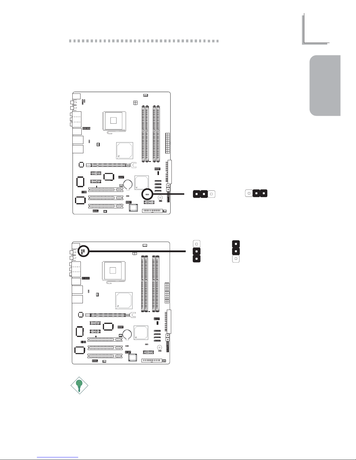
1.2 Jumpers
1.2.1 Clear CMOS Data
JP8
2-3 On:
Clear CMOS Data
1-2 On: Normal
(default)
X
JP4
312
312
JP8
1.2.2 PS/2 Power Select
X
JP1
2-3 On: 5VSB
1-2 On: 5V
(default)
3
1
2
3
1
2
Important:
The 5VSB power source of your power supply must support
≥
720mA.
Page 6
6
Quick Setup Guide
1
Quick Setup
Guide
JP8
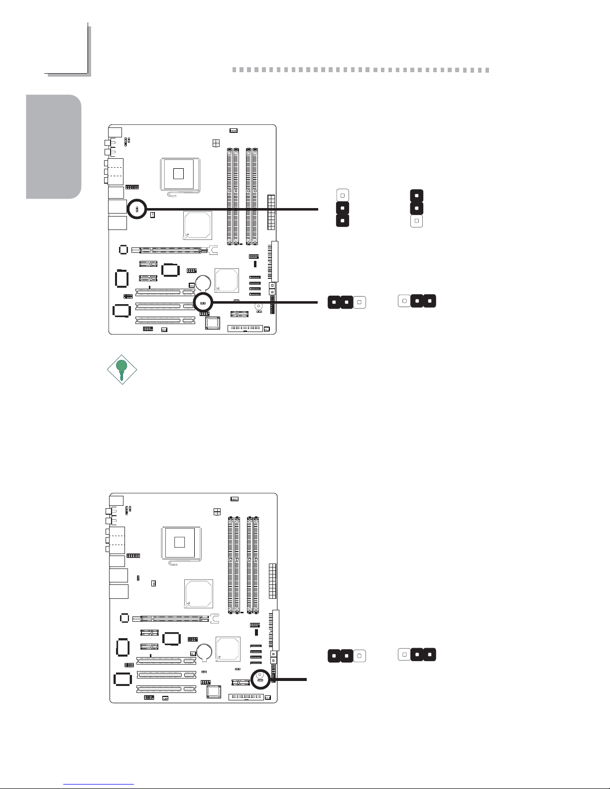
1.2.3 USB Power Select
X
USB 1-6
(JP2)
3
1
2
3
1
2
2-3 On: 5VSB1-2 On: 5V
(default)
312
312
2-3 On: 5VSB
1-2 On: 5V
(default)
X
USB 7-8
(JP3)
Important:
If you are using the Wake-On-USB Keyboard/Mouse function for 2
USB ports, the 5VSB power source of your power supply must
support ≥1.5A. If you are using the Wake-On-USB Keyboard/Mouse
function for 3 or more USB ports, the 5VSB power source of your
power supply must support ≥2A.
JP8
1.2.4 Speaker On/Off Select
X
JP8
312
312
2-3 On:
Speaker On
(default)
1-2 On:
Speaker Off
Page 7
7
1
Quick Setup Guide
Quick Setup
Guide
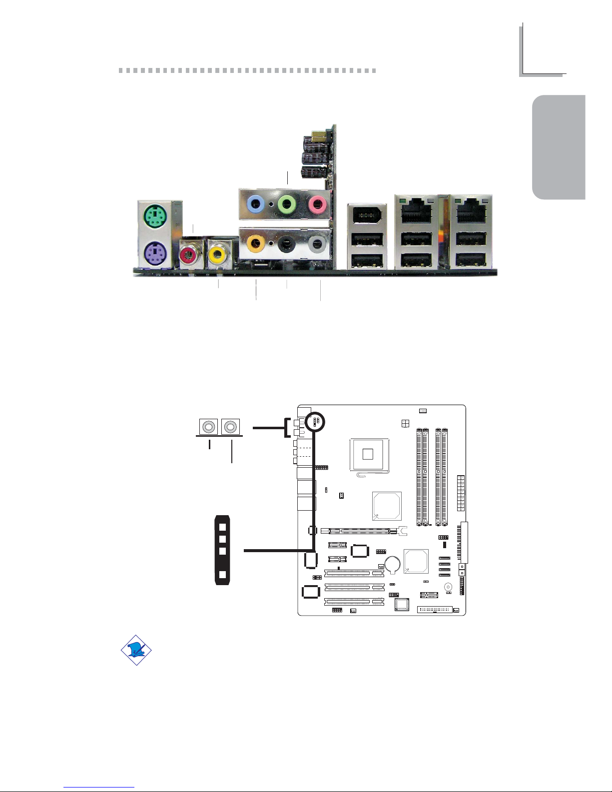
1.4 I/O Connectors
1.3 Rear Panel I/O Ports
JP8
W
1.4.1 S/PDIF-in/out Jacks
W
Optical S/PDIF
J1
S/PDIF-in
S/PDIF-out
1
5
+5V
Key
SPDIF out
GND
SPDIF in
Note:
DO NOT use RCA S/PDIF and optical S/PDIF at the same time.
PS/2
Mouse
PS/2
K/B
S/PDIF-in
S/PDIF-out
Line-in
Front R/L
(Line-out)
Mic-in
Center/
Subwoofer
Rear R/L
Side R/L
1394_1
USB 1-2 USB 3-4 USB 5-6
LAN 2LAN 1
Page 8
8
Quick Setup Guide
1
Quick Setup
Guide
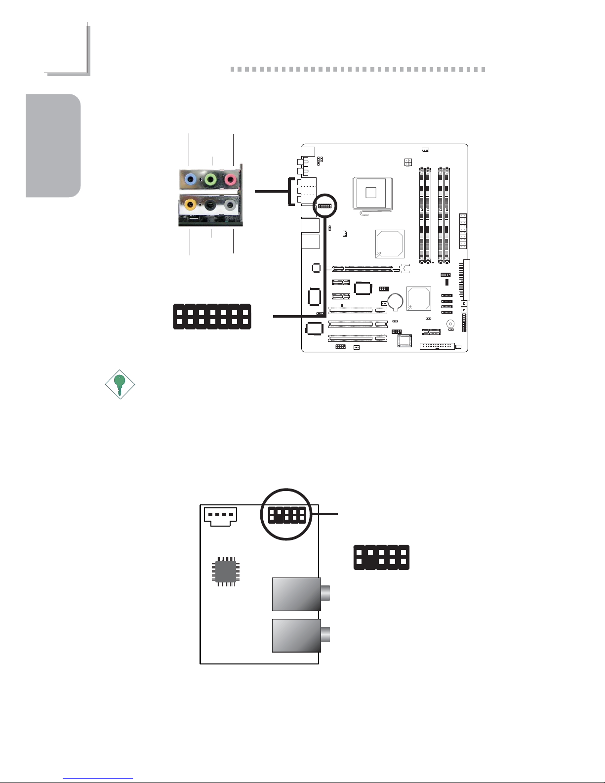
1.4.2 Karajan Audio Card
Important:
The adhesive tape on the Karajan card is used to stabilize the card
to the system board. Peel off the strip of the adhesive tape then
insert the 14-pin connector at the solder side of the card to J5 on
the system board.
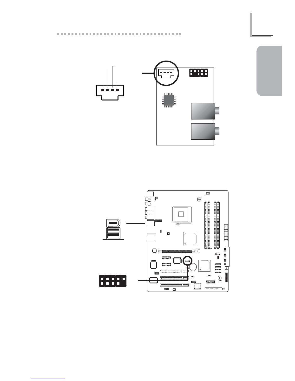
1.4.3 Front Audio Connector
Audio
codec
1
1
Line-in
Front R/L
Mic-in
Center/Subwoofer
Rear R/L
Side R/L
X
1
2
10
9
Mic_LeftGND
Mic_Right
Vcc
Line out_Right
Mic Jet Detect
Sense
N. C.
Line out_Left
Line out Jet Detect
The front audio connector (J4) on the Karajan audio add-in card allows
you to connect to the line-out and mic-in jacks that are at the front panel
of your system.
JP8
W
1
2
13
14
W
J5
Line-in
Front R/L
(Line-out)
Mic-in
Center/
Subwoofer
Rear R/L
Side R/L
Page 9
9
1
Quick Setup Guide
Quick Setup
Guide
Audio
codec
1
1
Line-in
Front R/L
Mic-in
Center/Subwoofer
Rear R/L
Side R/L
X
1.4.4 CD-in Internal Audio Connector
14
Right audio
channel
Left audio
channel
Ground Ground
JP8
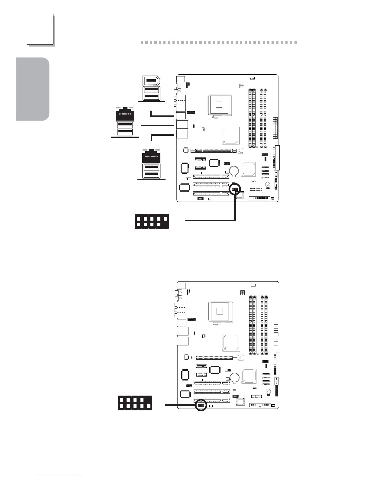
1.4.5 IEEE 1394
1394_1
W
W
1394_2
+12V (fused)
1
TPA+
Ground
TPB+
+12V (fused)
Key
TPA-
Ground
TPB-
Ground
2
10
9
The CD-in (J2) connector on the Karajan audio add-in card is used to
receive audio from a CD-ROM drive, TV tuner or MPEG card.
Page 10
10
Quick Setup Guide
1
Quick Setup
Guide
JP8
USB 4
USB 3
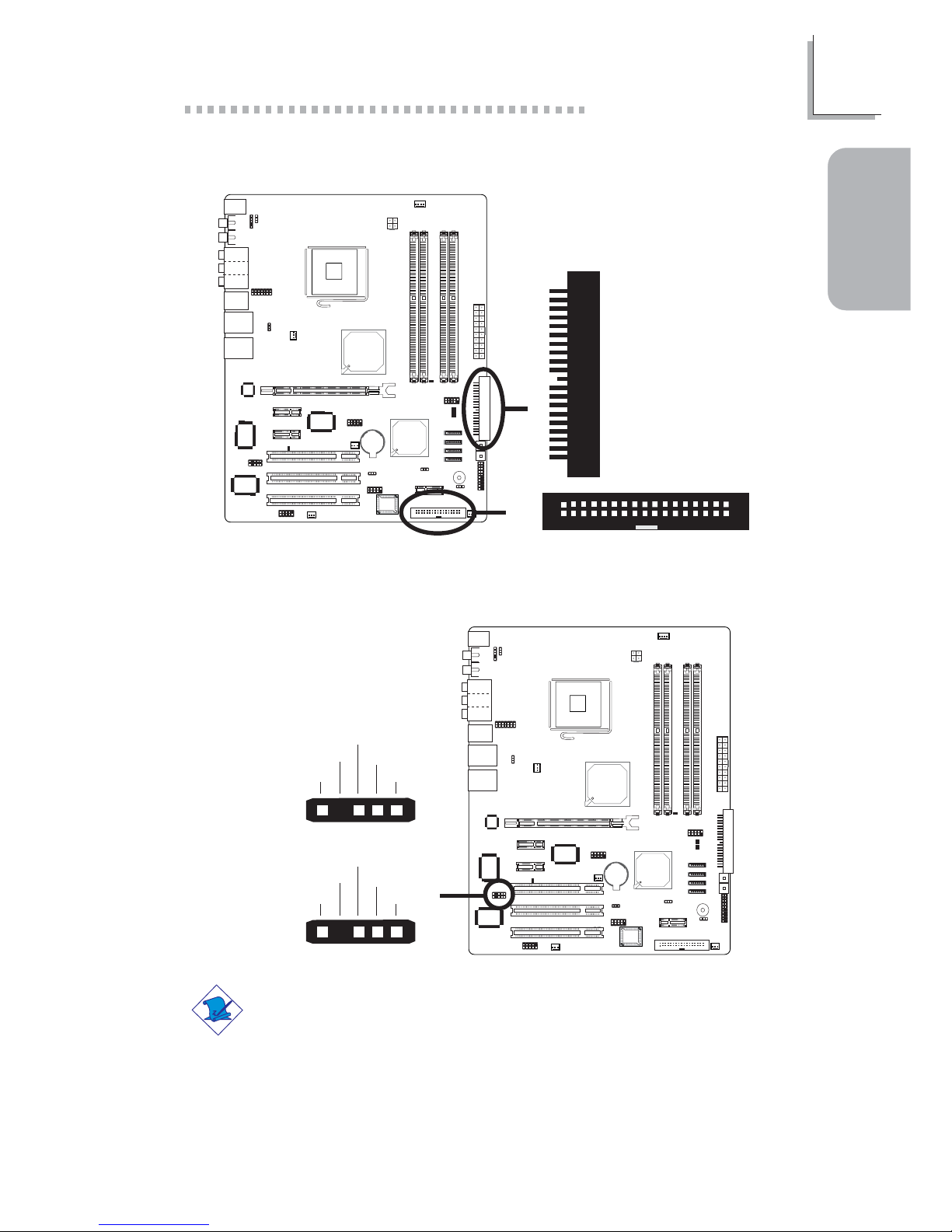
1.4.6 Universal Serial Bus Ports
1
VCC
-Data
+Data
Ground
Key
VCC
-Data
+Data
Ground
N. C .
2
10
9
USB 6
USB 5
W
W
USB 2
USB 1
W
USB 7-8
W
JP8
1.4.7 Serial Ports
X
1
9
2
CD
TD
RD
DTR
SG
RTS
DSR
CTS
RI
Page 11
11
1
Quick Setup Guide
Quick Setup
Guide
JP8
1.4.8 FDD and IDE Connectors
X
2
133
34
X
IDE
FDD
JP8
1.4.9 IrDA Connector
W
15
VCC
N. C.
IRRX
Ground
IRTX
CIR
IR
15
5VSB
N. C .
CIRRX
GND
CIRTX
Note:
The sequence of the pin functions on some CIR/IR cable may be
reversed from the pin function defined on the system board. Make
sure to connect the cable connector to the CIR/IR connector
according to their pin functions.
Page 12

12
Quick Setup Guide
1
Quick Setup
Guide
JP8
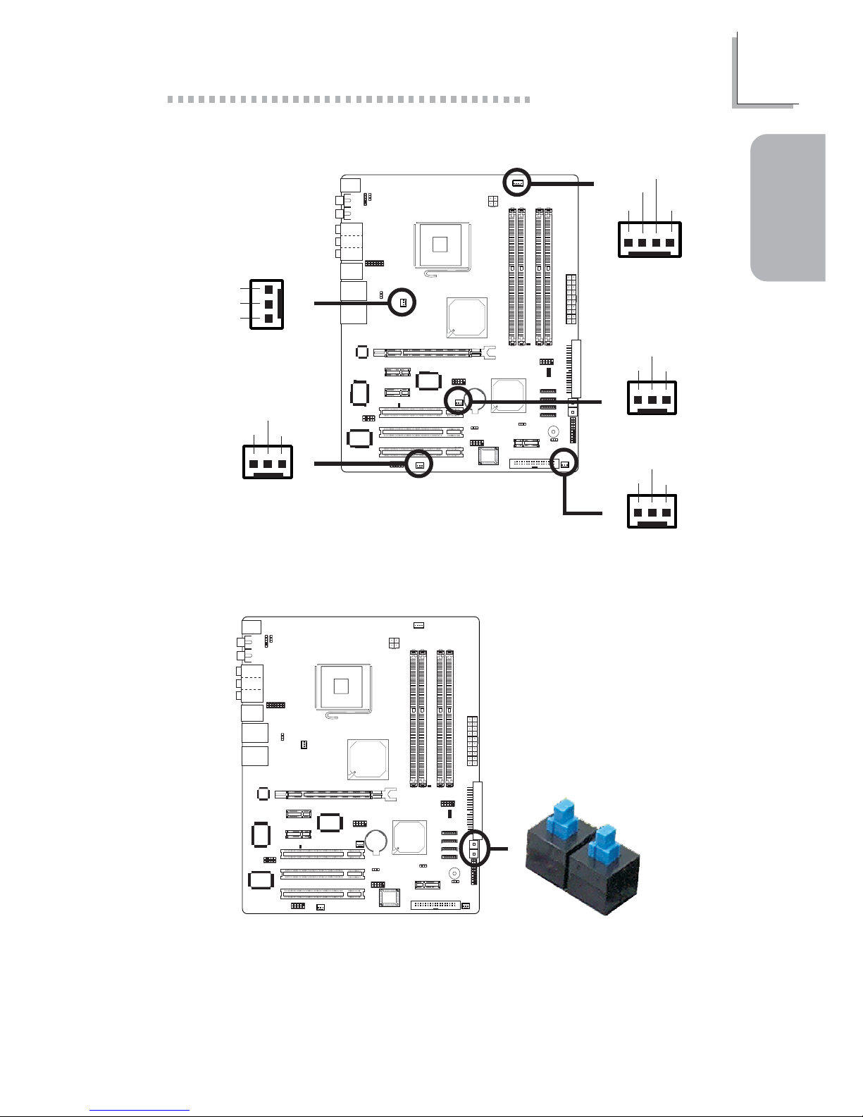
1.4.10 Serial ATA Connectors
X
SATA 2
SATA 1
GND
TXP
TXN
GND
RXN
RXP
GND
17
17
17
17
SATA 4
SATA 3
Serial ATA to Parallel ATA Adapter Module
The SATA to PATA module provides more flexibility to the system board
by allowing you to connect an additional parallel IDE drive via a SATA
connector and supports RAID spanning across SATA and PATA drives.
Power connector:
connect to power supply
Serial ATA connector :
connect to the Serial ATA
of the system board
IDE connector: connect
to parallel ATA drive
The ICH6R south bridge chip allows configuring RAID on serial ATA drives.
It supports RAID 0, RAID 1 and JBOD.
Page 13
13
1
Quick Setup Guide
Quick Setup
Guide
The presence of the power switch and reset switch on the system board
are user-friendly especially to DIY users. They provide convenience in
powering on and/or resetting the system while fine tuning the system
board before it is installed into the system chassis.
JP8
1.4.12 EZ Touch Switches
X
Reset Switch
Power Switch
JP8
1.4.11 Cooling Fan Connectors
X
X
X
X
Fan 2
CPU fan
Fan 5
4
1
Sense
Power
Ground
Speed
Control
13
Ground
Power
Sense
X
Fan 3
13
Ground
Power
Sense
1
3
Ground
Power
Sense
Fan 4
13
Ground
Power
Sense
Page 14
14
Quick Setup Guide
1
Quick Setup
Guide
JP8
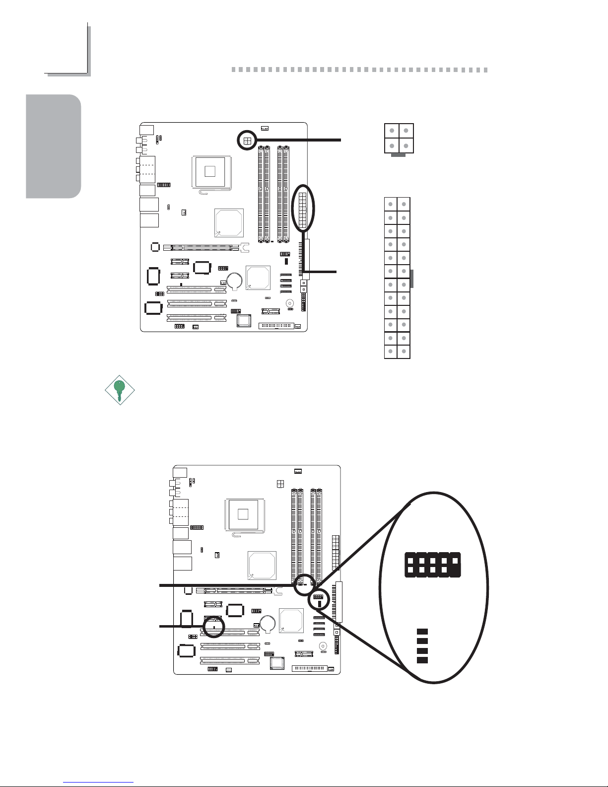
1.4.14 LEDs
Standby
Power LED
DRAM
Power LED
Diagnostic LEDs
1
D-LED1+
2
10
9
D-LED2+
D-LED3+
D-LED4+
Key
D-LED1-
D-LED2-
D-LED3-
D-LED4-
N. C.
LED 1
LED 2
LED 3
LED 4
J3
Important:
To ensure that adequate power is provided, we strongly recommend
that you use a minimum of 400 Watt (or greater) power supply.
JP8
1.4.13 Power Connectors
X
X
+12V
4
3
12
GroundGround
+12V
131
12 24
+3.3VDC
+3.3VDC
COM
+5VDC
COM
+5VDC
COM
PWR_OK
+5VSB
+12VDC
+12VDC
+3.3VDC
+3.3VDC
-12VDC
COM
PS_ON#
COM
COM
COM
NC
+5VDC
+5VDC
+5VDC
COM
Page 15
15
1
Quick Setup Guide
Quick Setup
Guide
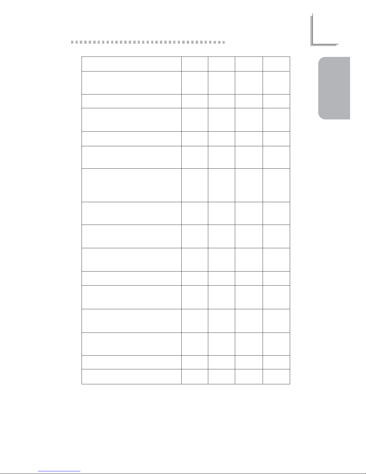
Early program chipset
register before POST.
Testing memory presence.
Detecting memory size.
No memory present.
Programming DRAM timing
register.
Calculating DRAM size
variable including row,
column and bank.
Initializing JEDEC of current
DRAM row.
Checking CMOS checksum
and battery.
Initializing the clock
generator.
Initializing USB.
Testing all memory (cleared
all extended memory to 0).
Initializing the onboard
Super IO.
Detecting and installing an
IDE device.
Final initialization.
Booting the system.
LED 1
On
Off
On
Off
On
Off
On
Off
On
Off
On
Off
On
Off
On
LED 2
Off
On
On
Off
Off
On
On
Off
Off
On
On
Off
Off
On
On
LED 3
Off
Off
Off
On
On
On
On
Off
Off
Off
Off
On
On
On
On
LED 4
Off
Off
Off
Off
Off
Off
Off
On
On
On
On
On
On
On
On
Page 16
16
Quick Setup Guide
1
Quick Setup
Guide
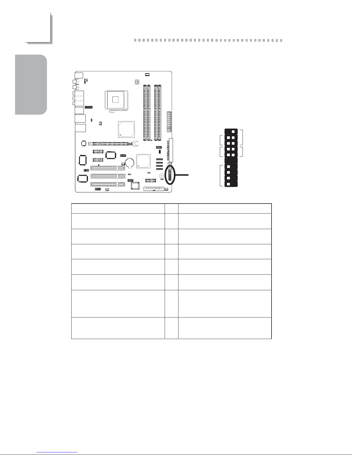
Pin
3
5
14
16
8
10
18
20
7
9
13
15
17
19
2
4
6
HD-LED
(Primary/Secondary IDE LED)
Reserved
ATX-SW
(ATX power switch)
Reserved
RESET
(Reset switch)
SPEAKER
(Speaker connector)
PWR-LED
(Power/Standby LED)
Pin Assignment
HDD LED Power
HDD
N. C.
N. C.
PWRBT+
PWRBT-
N. C.
N. C.
Ground
H/W Reset
Speaker Data
N. C.
Ground
Speaker Power
LED Power (+)
LED Power (+)
LED Power (-) or Standby Signal
1.4.15 Front Panel Connectors
JP8
X
J15
1
2
19
20
PWR-LED
ATX-SW
HD-LED
RESET
SPEAKER
Page 17
17
2
English
English
Chapter 2 - English
2.1 Features and Specifications
Processor
• Intel
®
Pentium® 4 Prescott processor
- Hyper-Threading Technology
- 800MT/s (200MHz) system bus interface
• Socket LGA 775 (LAN Grid Array)
Chipset
• Intel
®
925X chipset
- Intel® 925X Memory Controller Hub (MCH)
- Intel® 82801FR I/O Controller Hub (ICH6R)
System Memory
• Four 240-pin DDR2 DIMM sockets
• Supports dual channel (128-bit wide) memory interface
• Supports up to 4GB system memory
• Supports DDR2 400 and DDR2 533 DIMMs
• Supports non-ECC x8 and x16 DIMMs
• Support for 256Mb and 512Mb DRAM densities
• Supports Performance Acceleration Technology
• Supports unbuffered DIMMs
BIOS
• Award BIOS
• Genie BIOS provides:
- CPU/DRAM overclocking
- CPU/NB/DRAM overvoltage
• Supports SCSI sequential boot-up
• Supports DMI 2.0 function
• 4Mbit flash memory
Energy Efficient Design
• Supports ACPI specification and OS Directed Power
Management
• Supports ACPI STR (Suspend to RAM) function
• Wake-On-Events include:
- Wake-On-PS/2 Keyboard/Mouse
- Wake-On-USB Keyboard/Mouse
Page 18
18
English
2
English
- Wake-On-Ring (external modem) and Wake-On-LAN
- RTC timer to power-on the system
• AC power failure recovery
Hardware Monitor
• Monitors CPU/system temperature and overheat alarm
• Monitors 12V/5V/3.3V/Vcore/Vbat/5Vsb/3.3Vsb voltages
• Monitors the speed of the CPU/system fan
• CPU Overheat Protection function monitors CPU temperature
and fan during system boot-up - automatic shutdown upon
system overheat
Onboard Audio Features
• Azalia audio codec with independent variable sampling rate
• True stereo line level outputs
• S/PDIF-in/out interface
• 8-channel audio output
Onboard LAN Features
• Gigabit ethernet controllers - Mar vell 88E8053 PCI Express and
Marvell 88E8001 PCI
• Integrated power management functions
• Full duplex support at both 10 Mbps, 100 Mbps and 1Gbps
• Supports IEEE 802.3u auto-negotiation
• Supports wire for management
Serial ATA Interface with RAID
• Supports four SATA (Serial ATA) interfaces which are compliant
with SATA 1.0 specification (1.5Gbps interface)
• Supports RAID 0, RAID 1 and JBOD
IEEE 1394 Interface
• Supports two 100/200/400 Mb/sec ports
IDE Interface
• Supports ATA/33, ATA/66 and ATA/100 hard drives
Rear Panel I/O Ports
• 1 PS/2 mouse port and 1 PS/2 keyboard port
• 2 S/PDIF RCA jacks (S/PDIF-in and S/PDIF-out)
• Karajan audio card (6 audio jacks)
• 1 IEEE 1394 port and 2 RJ45 LAN ports
• 6 USB 2.0/1.1 ports
Page 19
19
2
English
English
I/O Connectors
• 1 connector for 2 additional external USB 2.0/1.1 ports
• 1 connector for 1 external IEEE 1394 port
• 1 connector for 1 external serial por t
• 1 front audio connector for external line-out and mic-in jacks
• 1 CD-in internal audio connector
• 1 S/PDIF connector for optical cable connection
• 1 IR connector and 1 CIR connector
• 4 Serial ATA connectors
• 1 IDE connector and 1 floppy connector
• 2 ATX power supply connectors
• 5 fan connectors
• 4 diagnostic LEDs
• 1 diagnostic LED connector for external 4 diagnostic LEDs
display
• EZ touch switches (power switch and reset switch)
Expansion Slots
• 1 PCI Express x16 slot
• 3 PCI Express x1 slots
• 3 PCI slots
Compatibility
• PCI 2.2 and Azalia compliant
PCB
• 6 layers, ATX form factor
• 24.5cm (9.64") x 30.5cm (12")
2.2 CMOS Reloaded
CMOS Reloaded allows you to save different configurations and
when needed, allows you to conveniently restore one of these previously saved configurations. CMOS Reloaded is especially helpful to
overclockers who often go through the tiresome trial and error
process of repeatedly changing the BIOS settings to come up with
the most ideal overclocked setting. By being able to save and load
the settings, it eliminates the tedious job of remembering several
settings and/or repeatedly resetting settings during the trial process.
The settings are stored in the SEEPROM. SEEPROM is divided into 5
banks - the backup bank and the 4 user defined banks.
Page 20
20
English
2
English
Auto Save Bootable Setting
This field is used to automatically save the last bootable setting from
CMOS to an area in the SEEPROM referred to as the backup bank.
To use this function:
1. Set this field to Enabled.
2. Select “Save & Exit Setup” in the main menu then press <Enter>.
3. Type <Y> then press <Enter>.
If the changes to the setting allowed the system to boot, the setting
will be stored in the SEEPROM. In other words, if the system did not
boot up, the setting will not be stored. You may then follow the
steps in the next section to load the last bootable setting.
Load Last Bootable Setting
If, during the trial and error process, the setting resulted to the
system’s instability or worse yet, not being able to boot up the
system, please follow the steps below to use the Load function.
Note:
You can use the Load function only if you have set the “Auto
Save Bootable Setting” to Enabled.
1. If the system did not boot up properly but you were able to
enter the BIOS utility:
a. Select “CMOS Reloaded” in the main menu then press
<Enter>.
b. Move the cursor to “Load Last Bootable Setting” then press
“Load”.
c. Press <Y> to load the last bootable setting that was stored
in the backup bank.
2. If you cannot enter the BIOS utility:
a. Use JP3 to clear the CMOS. Refer to chapter 1 for more
information about clearing CMOS.
b. Enter the BIOS utility then perform steps 1a to 1c.
Saving, Loading and Naming BIOS Settings
For overclockers who require different sets of settings for various
system environments or operating systems, CMOS Reloaded allows
you to save, load and name up to four sets of BIOS settings - in
Page 21
21
2
English
English
the “User Defined Setting Bank #1” to “User Defined Setting Bank
#4” fields.
Save Setting to Bank With
This field is used to select the type of setting you would like saved
to a User Defined Setting Bank when you use the “Save to this
Bank” function of that bank.
Current BIOS Setting This option will save the current BIOS setting
to the User Defined Setting Bank.
Last BIOS Setting This option will save the last saved BIOS
setting to the User Defined Setting Bank.
User Defined Setting Bank #1/2/3/4
Bank Description
To name the BIOS setting, move the cursor to “Bank Description”
then press <Enter>. You can enter up to 60 characters. Providing a
name to the BIOS setting will allow you to easily remember the
settings in the bank.
Save to this Bank
To save the BIOS setting, move the cursor to “Save to this Bank”
then press <Enter>. Type <Y> then press <Enter>. This will save the
current setting or the last saved setting to this bank; depending on
the option selected in the “Save Setting to Bank With” field. If you
want to immediately reboot to use the new settings, make sure to
save before you exit the BIOS setup utility by selecting “Y” in the
“Save & Exit Setup” submenu.
Load from this Bank
To load the setting saved in the bank, move the cursor to “Load
from this Bank” then press <Enter>. The setting in this bank will
replace the current setting. Make sure to save before you exit the
BIOS setup utility by selecting “Y” in the “Save & Exit Setup”
submenu.
Hotkey
You can now load a BIOS setting during system boot up; bypassing
the lengthy process of entering the BIOS utility to load a setting.
Move the cursor to “Hotkey” then press <Enter>. Select the key you
would like to use to load the settings from the bank. When the
system boots up, press the key to load the setting.
Page 22
22
English
2
English
2.3 Package Checklist
The system board package contains the following items:
; One LANPARTY 925X-T2 system board
; One Karajan audio card
; One Serial ATA to Parallel ATA adapter module
; One Serial ATA power cable for the adapter module
; One IDE round cable
; One floppy round cable
; Two Serial ATA data cables
; One Serial ATA power cable
; One card-edge bracket mounted with a DB-9 serial port
; One I/O shield
; One I/O shield label sticker
; One thermal paste
; One PC Transpo kit
; One FrontX device equipped with:
- 4 diagnostic LEDs
- 1 S/PDIF-out jack
- 1 mini 1394 port
- 1 Serial ATA por t
; One LANPARTY sticker
; One case badge
; One UV sleeve
; One “Intel ICH6R RAID Driver” diskette
; One “Mainboard Utility” CD
; One LANPARTY 925X-T2 User’s Manual
; One LANPARTY Features User’s Manual
; One LANPARTY 925X-T2 Quick Installation Guide
; One CMOS Reloaded User Guide
If any of these items are missing or damaged, please contact your
dealer or sales representative for assistance.
Please refer to the LANPARTY Features manual for more information on the FrontX device.
Page 23
23
3
Français
Français
Chapter 3 - Français
3.1 Caractéristiques et Spécifications
Processeur
• Les processeurs Intel® Pentium® 4 Prescott
- Intel Hyper-Threading Technologie
- Interface du bus système 800MT/s (200MHz)
• Socket LGA 775 (LAN Grid Array)
Chipset
• Intel
®
925X chipset
- Intel® 925X Controlleur du Mémoire (MCH)
- Intel® 82801FR I/O Controleur Entrée/Sorrtie (ICH6R)
Mémoire Système
• Quatre sockets DIMM DDR2 240-pin
• Supporte l’interface de mémoire deux canaux (128-bit)
• Supporte jusqu’à 4 GB de mémoire système
• Supporte les modules DIMM DDR2 400 et DDR2 533
• Supporte exclusivement les modules DIMM non-ECC x8 et x16
• Supporte une densité de RAM de 256Mb et 512Mb
• Supporte la technologie de l’accélération de la performance
• Supporte les DIMM non-tamponnés
BIOS
• Compatible avec Award BIOS
• Le Genie BIOS offre:
- Overclocking de CPU/DRAM
- Contrôle du voltage de CPU/NB/DRAM
• Supporte la fonction DMI 2.0
• Mémoire Flash 4Mbit
Design à Haut Rendement Énergétique
• ACPI STR (Suspend to RAM) fonction
• Réveil-Sur-PS/2 Clavier/Souris et Réveil-Sur-USB Clavier/Souris
• Eveil Sonnerie et Réveil Par Le Réseau
• Minuterie RTC pour allumer le système
• Récupération après Défaillance d’Alimentation CA
Page 24
24
Français
3
Français
Français
System Health Monitor Fonctions
• Gère l’alarme de température et de surchauffe de CPU/système
• Gère l’alarme de voltage et d’échec de 12V/5V/3.3V/Vcore/
Vbat/5Vsb/3.3Vsb
• Gère la vitesse de ventilateur du ventilateur de CPU/système
• Protection du CPU - supporte la mise hors circuit automatique
en cas de surchauffage du système
Caractéristiques Audio sur Carte
• Codec Azalia avec fréquence d’échantillonnage variable
indépendante
• Sorties de niveau de lignes stéréo vraies
• Interface entrée/sor tie S/PDIF
• Sortie audio 8-canaux
Fonctionnalités Onboard LAN
• Gigabit LAN - Marvell 88E8053 PCI Express et Marvell
88E8001 PCI
• Fonctions de gestion d’alimentation intégrées
• Support Full duplex à 10 Mbps, 100 Mbps et 1Gbps
• Supporte l’auto négociation IEEE 802.3u
• Support câble pour la gestion
Interface Serial ATA avec RAID
• Supportant 4 interface SATA (Serial ATA) compatible avec la
spécification SATA 1.0 (bande passante à 1.5Gbps)
• Supporte RAID 0, RAID 1 et JBOD
Interface IEEE 1394
• Supporte 2 por ts 100/200/400 Mb/séc
Contrôleur IDE
• Supporte des disques durs ATA/33, ATA/66 et ATA/100
Le Panneau des Ports Entrée/Sortie en Arrière
• 1 port souris PS/2 et 1 por t clavier PS/2
• 2 S/PDIF RCA prises (S/PDIF-in et S/PDIF-out)
• 1 carte Karajan (6 prises audio)
• 1 port IEEE 1394, 2 ports RJ45 LAN et 6 por ts USB 2.0/1.1
Connecteurs Entrée/Sortie
• 1 connecteur pour 2 ports USB 2.0/1.1 supplémentaires
• 1 connecteur pour 1 IEEE 1394 et 1 connecteur pour 1 série
Page 25
25
3
Français
Français
• 1 connecteur audio de l’avant pour la sortie ligne/l’entrée micro
•1 connecteur CD-in audio internes
• 1 S/PDIF l’assemblage pour l’adjonction de câble optique
• 1 connecteur IR, 1 connecteur CIR et 4 connecteurs Serial ATA
• 1 connecteur IDE et 1 connecteur de FDD
• 2 connecteurs d’alimentation ATX
• 5 connecteurs de ventilateurs
• 4 indicateurs diagnostiques
• Un assemblage pour 4 exterieurs indicateurs diagnostiques
• EZ interrupteurs (bouton de power et reset)
Logements d’Extension
• 1 slot PCI Express x16
• 3 slots PCI Express x1
• 3 slots PCI
Compatibilité
• Compatible PCI 2.2 et Codec Azalia
PCB
• 6 couches, ATX, 24.5cm (9.64") x 30.5cm (12")
3.2 CMOS Reloaded
La technologie CMOS Reloaded permet d’enregistrer plusieurs
configurations du BIOS définies par l’utilisateur. Cette technologie sera
particulièrement utile aux overclockeurs, qui ont souvent besoin
d’enregistrer plusieurs configurations d’overclocking et de disposer
d’un procédé de commuter facilement entre ces configurations-là.
CMOS Reloaded aide surtout les overclockeurs, qui se voient
souvent obligés de mettre en place une recherche par tâtonnement
exténuante comprenant des changements répétés des réglages du
BIOS en quête d’une configuration d’overclocking parfaite. Puisqu’elle
permet aux utilisateurs d’enregistrer et de charger des configurations
différentes, cette technologie abolit le besoin ennuyeux de retenir
plusieurs configurations et/ou de les remettre à niveau initial lors des
essais d’overclocking. Les configurations sont conservées dans la
SEEPROM. La SEEPROM est divisée en 5 banques – la banque de
sauvegarde et 4 banques définies par l’utilisateur.
Auto Save Bootable Setting
Ce champ sert à enregistrer automatiquement la dernière
configuration réussie à partir de la CMOS dans la banque de
Page 26
26
Français
3
Français
Français
sauvegarde de la SEEPROM. Pour utiliser cette fonction:
1. Activez le champ (Sélectionnez “Enabled”).
2. Sélectionnez “Save & Exit Setup” dans le menu principal, puis
appuyez sur <Enter>.
3. Tapez <Y> et apuyez sur <Enter>.
Seulement si le système démarre avec la configuration modifiée, cette
configuration est conservée dans la SEERPOM. En d’autres mots, si le
système ne démarre pas, la configuration n’est pas conservée. La
section suivante offre les instructions à suivre pour charger la
dernière configuration réussie.
Load Last Bootable Setting
Si, en procédant par essais et erreurs, il vous arrive de régler une
configuration qui rend le système instable ou même ne permet pas
de démarrer le système, vous pouvez suivre les instructions cidessous pour vous servir de la fonction “Load”.
Remarque:
Cette fonction est exclusivement disponible lorsque le champ
“Auto Save Bootable Setting” est activé (lorsque vous avez
sélectionné “Enabled”).
1. Si le système ne démarre pas mais vous avez réussi à accéder
au BIOS:
a. Sélectionnez “CMOS Reloaded” dans le menu principal, puis
appuyez sur <Enter>.
b. Déplacez le curseur vers “Load Last Bootable Setting” et
appuyez sur “Load”.
c. Appuyez sur <Y> afin de charger la dernière configuration
réussie conservée dans la banque de sauvegarde.
2. Si vous n’arrivez pas à accéder au BIOS:
a. Utilisez JP3 pour vider la CMOS. Veuillez vous reporter au
chapitre 1 pour plus de renseignements sur le vidage de la
CMOS.
b. Entrez dans le BIOS et effectuez les étapes 1a – 1c.
Enregistrer, Charger et Nommer des Configurations du BIOS
Tenant compte des demandes des overclockeurs, qui veulent
disposer de configurations différentes pour des environnements et
des systèmes d’exploitaion différents, CMOS Reloaded permet
d’enregistrer, charger et nommer jusqu’à quatre configurations du
BIOS – dans les champs “User Defined Setting Bank #1” – “User
Defined Setting Bank #4”.
Page 27
27
3
Français
Français
Save Setting to Bank With
Dans ce champ-là, vous pouvez sélectionner le type de configuration
que vous souhaitez enregistrer dans une banque définie par
l’utilisateur lorsque vous effectuer la fonction “Save to this Bank”
(Enregistrer dans la banque choisie).
Current BIOS Setting Cette option enregistre la configuration du
BIOS courante dans la banque définie par
l’utilisateur.
Last BIOS Setting Cette option enregistre la dernière configuration
sauvegardée du BIOS dans la banque définie
par l’utilisateur.
User Defined Setting Bank #1/2/3/4
Bank Description (Descrption de la banque choisie)
Pour nommer votre configuration du BIOS, déplacez le curseur vers
“Bank Description” et appuyez sur <Enter>. Il est permis de saisir
jusqu’à 60 caractères. En attribuant un nom à votre configuration du
BIOS, vous pourrez retenir facilement le contenu de la banque.
Save to this Bank (Enregistrer dans la banque choisie)
Pour enregistrer une configuration, déplacez le curseur vers “Save to
this Bank” et appuyez sur <Enter>. Tapez <Y> et appuyez sur
<Enter>. Suivant l’option sélectionnée dans le champ “Save Setting
to Bank With”, la configuration courante ou la dernière configuration
sauvegardée sera enregistrée dans la banque choisie. Si vous
souhaitez redémarrer le système immédiatement afin d’utiliser la
nouvelle configuration, veuillez vous assurer d’enregistrer les
changements avant de quitter le menu du BIOS: sélectionnez “Y”
dans le sous-menu “Save & Exit Setup”.
Load from this Bank (Charger à partir da la banque choisie)
Pour charger la configuration conservée dans une banque, déplacez le
curseur vers “Load from this Bank” et appuyez sur <Enter>. La
configuration de la banque remplacera la configuration courante.
Veuillez vous assurer d’enregistrer les changements avant de quitter
le menu du BIOS: sélectionnez “Y” dans le sous-menu “Save & Exit
Setup”.
Hotkey (Touche rapide)
Vous pouvez aussi charger une configuration du BIOS pendant le
boot du système, sans avoir besoin d’accéder au BIOS, ce qui peut
Page 28
28
Français
3
Français
Français
prendre beaucoup de temps. Déplacez le curseur vers “Hotkey” et
appuyez sur <Enter>. Sélectionnez la touche que vous souhatez
utiliser pour charger les configurations à partir de la banque choisie.
Lorsque le système démarre, appuyez sur la touche rapide pour
charger la configuration.
3.3 Liste de Vérification de l’Emballage
L’emballage de la carte système contient les éléments suivants:
; 1 carte système de LANPARTY 925X-T2
; 1 carte audio Karajan
; 1 module SATA-PATA
; 1 câble d’alimentation SATA pour module SATA-PATA
; 1 câble rond IDE
; 1 câble rond floppy
; 2 câble SATA
; 1 câble d’alimentation SATA
; 1 bracket fourni d’un port en série DB-9
; 1 plaque I/O
; 1 étiquette sur la plaque I/O
; 1 pâte silicone (composé à base du silicone)
; 1 sac PC Transpo
; 1 kit FrontX
- 4 indicateurs diagnostiques
- 1 jack de S/PDIF-out
- 1 port mini 1394
- 1 port SATA
; 1 étiquette LANPARTY
; 1 case badge
; 1 manchon UV
; 1 disquette “Intel ICH6R RAID Drivers”
; 1 CD “Mainboard Utility”
; 1 manuel utilisateur LANPARTY 925X-T2
; 1 manuel utilisateur “LANPARTY Features”
; 1 guide d’Installation rapide LANPARTY 925X-T2
; 1 guide d’Installation rapide CMOS Reloaded
Si l’un de ces éléments n’était pas dans l’emballage ou s’il était
endommagé, veuillez contacter votre revendeur ou votre
représentant. Veuillez vous reporter au manuel LANPARTY pour plus
d’information sur le périphérique FrontX.
Page 29
29
4
Deutsch
Deutsch
Chapter 4 - Deutsch
4.1 Leistungsmerkmale und Technische Daten
Prozessor
• Intel® Pentium® 4 Prescott Prozessor
- Intel Hyper-Threading Technologie
- Interface des Systemreifens 800MT/s (200MHz)
• Prozessor Socket LGA 775 (LAN Grid Array)
Chipset
• Intel
®
925X chipset
- Intel® 925X Speichersteuerungs-Plattenmitte (MCH)
- Intel® 82801FR I/O Steuerungsplattenmitte (ICH6R)
Systemspeicher
• Vier 240-pin-Steckplätze DDR2 DIMM
• Unterhält 128-bit – Speiher mit den zwei Kanälen
• Unterhält bis zum 4GB-Systemspeicher
• Unterhält die Moduln DDR2 400 und DDR2 533 DIMMs
• Unterhält nur non-ECC x8 und x16 DIMMs
• Unterhält 256Mb und 512Mb DRAM
• Unterhält Performance Acceleration Technology
• Unterhält DIMMs ohne Dämpfer
BIOS
• Kompatibilität mit Award BIOS
• Genie BIOS gewährleistet:
- Die Frequenzerhöhung CPU/DRAM
- Die Spannungserhöhung CPU/NB/DRAM
• Unterstützung der DMI-2.0-Funktion
• Flash-Speicher (4Mbit)
Energomisches Design
• ACPI STR (Suspend to RAM) funktion
• Wecken bei Betätigung der PS/2 Tastatur/Maus
• Wecken bei USB-Tastatur/Maus
• Wecken bei Klingeln
• Wecken des Systems durch das Netzwerk
• RTC-Taktgeber zum Einschalten des Systems
Page 30
30
Français
4
Deutsch
Deutsch
• Wiederherstellung der Wechselstromversorgung nach einem
Ausfall
System Health Monitor Funktions
• Überwachung der Temperatur des CPU/Systems sowie
Warnsignal bei Überhitzung
• Überwachung der Spannungen des 12V/5V/3.3V/Vcore/Vbat/
5Vsb/3.3Vsb
• Überwachung der Geschwindigkeit des CPU-Ventilators und
Systems-Ventilators
• Prozessor-Shutz - Die Ausschaltung bei der Überhitzung – die
automatische Ausschaltung des Computers bei der Überhitzung
Audiomerkmale auf Platine
• Azalia-Codec mit unabhängiger und variabler Abtastfrequenz
• Naturgetreue Stereo-Leitungspegel-Ausgabe
• S/PDIF-In/Aus-Schnittstelle
• 8-Kanal-Audioausgang
Merkmale des LAN auf Platine
• Gigabit LAN - Marvell 88E8053 PCI Express und Marvell
88E8001 PCI
• Integrierte Power-Management-Funktionen
• Vollduplex-Unterstützung bei 10 Mbps, 100 Mbps und 1Gbps
• Unterstützung der IEEE-802.3u-Auto-Negotiation
• Unterstützung des Leiters für das Management
Serial ATA und RAID Schnittstelle
• Unterstützt 4 SATA (Serielle ATA)-Schnittstelle, die mit SATA 1.0
Spezifikation (1.5Gigabits Schnittstelle) konform ist.
• Unterstützt RAID 0, RAID 1 und JBOD
IEEE 1394 Schnittstelle
• Uunterstützt 2 Ports 100/200/400 Mbps
IDE-Controller
• Unterstützung der Festplatten ATA/33, ATA/66 und ATA/100
Ein-/Ausgabe-Porte an der Rückwand
• 1 Mini-DIN-6-Anschluß für eine PS/2-Maus
• 1 Mini-DIN-6-Anschluß für eine PS/2-Tastatur
• 2 S/PDIF RCA-Anschlüsse (S/PDIF-in und S/PDIF-out)
• Karajan-platine (6 Audio-Anschlußbuchsen)
Page 31
31
4
Deutsch
Deutsch
• 1 IEEE 1394-Anschlüsse
• 2 RJ45 LAN-Anschlüsse
• 6 USB 2.0/1.1-Anschlüsse
Ein-/Ausgabe-Steckverbinder
•1 Anschlußfassung für 2 zusätzliche externe USB 2.0/1.1-
Anschlüsse
• 1 Anschluß für eine externe IEEE 1394 Schnittstelle
• 1 Anschluß für eine externe serieller DB-9-Anschluß
• 1 Frontaudioanschluß für die externe Ausgangsleitung und den
Mikrofoneingang
• 1 interne Audioanschlüsse (CD-in)
• 1 S/PDIF Anschluß für die Verbindung des optischen Kabel
• 1 Anschluß für die IR-Schnittstelle
• 1 Anschluß für die CIR-Schnittstelle
• 4 Serial-ATA-Anschlüsse
• 1 IDE-Anschlüsse
• 1 Floppy-Anschlüsse
• 2 Anschlußstecker für das ATX-Netzgerät
• 5-ventilator-Anschlüsse
• 4 diagnostischen Außenindikatoren
• Ein Anschluß für 4 diagnostischen Außenindikatoren
• EZ Umschaltern (der Knopf der Speisung und des Auslasses)
Erweiterungssteckfasssungen
• 1 PCI Express x16-Einbauplätzen
• 3 PCI Express x1-Einbauplätzen
• 3 PCI-Einbauplätzen
Kompatibilität
• Kompatibilität mit PCI 2.2 und Azalia-Codec
Die Druckplatte
• 6 Variationen, ATX
• 24.5cm (9.64") x 30.5cm (12")
4.2 CMOS Reloaded
Die Technologie CMOS Reloaded gibt dem Benutzer die Möglichkeit
der Erhaltung von einigen BIOS-Konfigurationen. Diese Funktion ist
besonders nutzbringend für die Overclockers, die brauchen während
des Anfahrens des Systemes, die Einrichtungen zu halten und
Page 32
32
Français
4
Deutsch
Deutsch
zwischen ihnen umzuschalten. Die Funktion CMOS Reloaded ist
besonders nützlich für die Overclockers, die oft durch den
ermüdenden Weg der Proben und der Fehler im Laufe des BIOSEinrichtens bis zu den optimalen Kennziffern gehen müssen. Jetzt
können Sie die Einrichtungen behalten und hochfahren und dafür
keine ermüdende Arbeit machen und sich keine Parameter ins
Gedächtnis rufen oder zurückrufen. Die Einrichtungen werden in
SEEPROM gehalten. SEEPROM ist in 5 Banken des Speichers geteit.
Das sind ein vorrätiger Datenbank und 4 Datenbanken für die
Bedüfnisse des Benutzers.
Auto Save Bootable Setting
Dieses Feld ist für die automatische Erhaltung des letzten
hochfahrenden CMOS in SEEPROM benützt, der beim vorrätiger
Datenbank gannant ist. Für die Benutzung dieser Funktion brauchen
Sie:
1. Das Feld auf Enabled einrichten.
2. “Save & Exit Setup” im Hauptmenü wählen und <Enter>
pressen.
3. <Y> einführen und <Enter> pressen.
Wenn die eingetragenen Veränderungen werden lassen, den
Computer hochzufahren, dann werden die neuen Einrichtungen in
SEERPOM aufnehmen. Anders ausgedrückt, wenn das System nicht
hochfahren wird, so werden die Einrichtungen nicht behalten. Für das
Hochfahren der letzten hochfahrenden Aufnahme, folgen Sie, bitte, den
Instruktionen, die im folgenden Teil bezeichnet sind.
Load Last Bootable Setting
Wenn im Laufe der Einrichtung das System unsicher arbeitet oder
noch mehr Sie es nicht hochfahren können, nutzen Sie, bitte, die
Funktion des Hochfahrens solcherweise:
Bemerkung;
Sie können die Funktion des Hochfahrens benutzen, nur wenn
das Feld “Auto Save Bootable Setting” zu Enabled umgeschaltet
ist.
Page 33
33
4
Deutsch
Deutsch
1. Wenn der Computer nicht hochfährt, können Sie im BIOS
eingehen:
a. Wählen Sie “CMOS Reloaded” im Hauptmenü und pressen
<Enter>.
b. Stellen Sie den Cursor zu “Load Last Bootable Setting” um
und pressen “Load”.
c. Pressen Sie <Y>, um die letzte hochfahrende Konfiguration
aus den vorrätigen Datenbank hochzufahren.
2. Wenn Sie in BIOS nicht eingehen können:
a. Mit Hilfe von JP3 machen Sie CMOS frei. Für mehr
Information über die Freimachen CMOS richten Sie sich nach
dem 1 Kapitel.
b. Gehen Sie in BIOS ein und erfühlen Sie die Schritte von 1a
bis 1c.
Die Erhaltung, das Hochfahren und der Name von SIOSKonfigurationen
Für die Overclockers, die oft die verschiedenen Konfigurationen je
nach der Systemumgebung oder je nach den operativen Systemen
einrichten brauchen, läßt CMOS Reloaded die SIOS-Konfigurationen
behalten, hochfahren und nennen - von “User Defined Setting Bank
#1” bis “User Defined Setting Bank #4”.
Save Setting to Bank With
Dieses Feld ist für die Wahl des Typus der Konfiguration benützt, die
Sie in User Defined Setting Bank bei der Benutzung der Funktion
“Save to this Bank“ behalten wollen.
Current BIOS Setting Option wird diese BIOS-Konfiguration in User
Defined Setting Bank behalten.
Last BIOS Setting Option wird die letzte behaltende BIOS-
Konfiguration in User Defined Setting Bank
behalten.
User Defined Setting Bank #1/2/3/4
Bank Description
Für die Nennung der BIOS-Konfiguration stellen Sie den Cursor zum
Feld “Bank Description” um und pressen <Enter>. Sie können bis zu
60 Symbolen einführen. Wenn Sie den Name für BIOS geben
Page 34
34
Français
4
Deutsch
Deutsch
werden, dann werden Sie alle seine Grundeinrichtungen leicht
behalten.
Save to this Bank
Für die Erhaltung der BIOS-Konfiguration stellen Sie den Cursor zum
Feld “Save to this Bank” um und pressen <Enter>. Führen Sie <Y>
ein und dann pressen Sie <Enter>. Sie werden die gegebene oder
die letzte Konfiguration in diesem Datenbank je nach der gewählten
Option im Feld “Save Setting to Bank With” behalten.
Wenn Sie für die Bunutzung der neuen Einrichtungen sofort
wiederhochfahren wollen, behalten Sie sich unbedingt vor dem
Austritt aus BOIS. Und dafür wählen Sie, bitte, “Y” in “Save & Exit
Setup”.
Load from this Bank
Um die Konfiguration von diesem Datenbank hochzufahren, stellen
Sie den Cursor zu “Load from this Bank” um und pressen Sie
<Enter>. Die Einrichtungen dieser Konfiguration werden alle laufenden
Einregulierungen ersetzen, Und vor dem Austritt aus BIOS behalten
Sie sich unbedingt. Dafür wählen Sie, bitte, “Y” in “Save & Exit Setup”.
Hotkey
Sie können BIOS im Laufe des Hochfahren des Systems hochfahren
und durch den dauernden Prozeß des Eintritts in BIOS und der Wahl
von der Konfiguration für das Hochfahren nicht gehen. Stellen Sie den
Cursor zu “Hotkey” und pressen Sie <Enter>. Pressen Sie den Knopf,
mit dessen Sie die Einrichtungen aus den Datenbanck hochfahren
wollen. Man muss diesen Knopf für das Hochfahren der Konfiguration
im Laufe der Schaltung des Computers pressen.
Page 35
35
4
Deutsch
Deutsch
4.3 Verpackungsliste
In der Verpackung der Systemplatine sind folgende Artikel enthalten:
; 1 Systemplatine LANPARTY 925X-T2
; 1 Karajan-platine
; 1 Übergangsstück SATA zu PATA
; 1 SATA-Energiekabel-Kabel für Übergangsstück SATA zu PATA
; 1 runde IDE-Kabel
; 1 runde Floppy-Kabel
; 2 SATA-Kabel
; 1 SATA-Energiekabel-Kabel
; 1 Leiste mit dem fortlaufenden serieller DB-9-Port
; 1 I/O-Shutzdeckel
; 1 I/O-Sticker des Schutzdeckels
; 1 Silikonpaste (das Silikon als die Basis)
; 1 PC Transpo-Satz
; Eine FrontX-Einrichtung
- 4 diagnostischen Außenindikatoren
- 1 Stecker vom S/PDIF-out
- 1 Mini 1394 Por te
-1 SATA Porte
; 1 LANPARTY-Klebezettel
; 1 Abzeichen für das Gehäuse
; 1 UV-Muffe
; 1 Diskette “Intel ICH6R RAID Driver”
; 1 CD mit “Mainboard Utility”
; 1 Benutzerhandbuch LANPARTY 925X-T2
; 1 Benutzerhandbuch “LANPARTY Features”
; 1 Schnellinstallationsanleitung LANPARTY 925X-T2
; 1 Schnellinstallationsanleitung CMOS Reloaded
Fehlt einer dieser Artikel oder weist einer dieser Artikel
Beschädigungen auf, wenden Sie sich an Ihren Händler oder Vertreter.
Nach genauerer Information über die Einrichtung von FrontX schauen
Sie die LANPARTY-Anleitung.
Page 36

36
5
Español
Español
Chapter 5 - Español
5.1 Características y Especificaciones
Procesador
• Procesador Intel® Pentium® 4 Prescott
- Intel Hyper-Threading Tecnología
- Interface de la barra sistémica 800MT/s (200MHz)
• Zócalo LGA 775 (LAN Grid Array)
Chipset
• Intel
®
925X chipset
- Hub de Controlador Memoria de Intel® 925X (MCH)
- Hub de Controlador I/O de Intel® 82801FR (ICH6R)
Memoria de Sistema
• Cuatro 240-pin mortajas DDR2 DIMM
• Soporta memoria de dos canales (128-bit)
• Soporta hasta 4 GB de memoria sistémica
• Soporta los módulos DIMM DDR2 400 y DDR2 533
• Soporta sólo non-ECC x8 y x16 DIMM
• Apoyo de 256 Mb y 512 Mb DRAM
• Soporta Performance Acceleration Technology
• Soporta unbuffered DIMM
BIOS
• Award BIOS
• Genie BIOS provee:
- Subida de frecuencia de CPU/DRAM
- Subida de voltaje de CPU/NB/DRAM
• Soporta la función de DMI 2.0
• Memoria Instante (4Mbitios)
Diseño Energia Eficiente
• ACPI STR (Suspend to RAM) función
• PS/2 Teclado/Ratón de Wake-On
• USB Teclado/Ratón de Wake-On
• Wake-On-Ring et Wake-On-LAN
• Temporizador de RTC para encender el sistema
• Recuperación de Fracaso de Energía AC
Page 37
37
5
Español
Español
Funciones de Monitor de Salud del Sistema
• Monitores de los CPU/sistema temperaturas y alarma acalorada.
• Monitores de voltajes de 12V/5V/3.3V/Vcore/Vbat/5Vsb/3.3Vsb
• Vigila la velocidad del abanico del abanido del CPU/sistema
• Protección del procesador - Desconección en caso de
recalentamiento –el ordenador se desconecta automáticamente
en caso de recalentamiento
Características de Audio En Tablero
• Codec Azalia dúplex completo estéreo de con independiente
frecuencia de muestreo variable
• Auténtico salidas de nivel de línea estéreo
• Interfáz de S/PDIF-in/out
• Output auricular de 8-canal
Características de LAN Interno
• Gigabit LAN - Marvell 88E8053 PCI Express y Marvell
88E8001 PCI
• Funciones de administración de energía integrado
• Soporte dúplex completo en ambos 10 Mbps, 100 Mbps y
1Gbps
• Soporta auto negociación de IEEE 802.3u
• Soporta alambre para la administración
Interfaz Serial ATA y RAID
• Permite 4 interfaz SATA (Serie ATA) la cual es compatible con la
especificación SATA 1.0 (interfaz 1.5Gbps)
• Se soporta RAID 0, RAID 1 y JBOD
Interfaz IEEE 1394
• Soporta 2 ports 100/200/400 Má/sec
Controlador de IDE
• Soporta las unidades duras de ATA/33, ATA/66 y ATA/100
Panel de reverso de conectores de entrada - Salida
• 1 puerto de ratón PS/2 mini-DIN-6
• 1 puerto de teclado mini-DIN-6 PS/2
• 2 enchufes de S/PDIF RCA (S/PDIF-in y S/PDIF-out)
• 1 tablero de Karajan (6 enchufes de audio)
• 1 puerto de IEEE 1394
• 2 puertos de RJ45 LAN
• 6 puertos de USB 2.0/1.1
Page 38
38
5
Español
Español
I/O Conectores
• 1 conector para 2 puertos de USB 2.0/1.1 externo adicional
• 1 conector para un puerto de IEEE 1394
• 1 conector para un puerto de DB-9 serie externa
• 1 conectador audio delantero para la salida extrema de linea y
el micro
• 1 conector de CD-in audio interno
• 1 S/PDIF mortaja para conección de cable óptico
• 1 conector de IR et 1 conector de CIR
• 4 conectores de Serial ATA
• 1 conector de IDE et 1 conector de FDD
• 2 conectores de fuente de alimentación de ATX
• 5 conectores de abanicos
• 4 indicadores diagnósticos
• Una mortaja para 4 indicadores diagnósticos externos
• EZ conmutadores (conmutadores de alimentación y reset)
Ranuras de Expansión
• 1 slot PCI Express x16
• 3 slot PCI Express x1
• 3 slots PCI
Compatibilidad
• Sumisión de PCI 2.2 y Azalia codec
La Placa Imprenta
• 6 variaciones, form-factor ATX
• 24.5cm (9.64") x 30.5cm (12")
5.2 CMOS Reloaded
La tecnología CMOS Reloaded permite conservar diferentes
configuraciones BIOS. Esta función es muy útil para overclockers,
quienes necesitan conservar unas configuraciones variadas y poder
conmutarlas. La función CMOS es especialmente útil para
overclockers, quienes necesitan pasar a menudo el camino de
errores y ensayos para ajustar configuraciones de BIOS de manera
más óptima. Ahora Vd puede conservar y cargar las configuraciones
evitando trabajo agotador, recuerdo y reconstitución de las
configuraciones. Las configuraciónes se conservan en SEEPROM.
SEEPROM está dividido en 5 bancas de memoria – la banca de
reserva y 4 bancas para el usuario.
Page 39
39
5
Español
Español
Auto Save Bootable Setting
Este campo se usa para conservar automáticamente el último
CMOS cargado en SEEPROM, que se llama la banca de reserva.
Para usar esta función se necesita:
1. Optar el campo de Enabled.
2. Optar “Save & Exit Setup” en el menú principal y apretar
<Enter>.
3. Entrar <Y> y apretar <Enter>.
Si las modificaciones realizadas permiten cargar el ordenador, las
nuevas configuraciones serán conservadas en SEERPOM. Con otras
palabras, si el sistema no se carga, las configuraciones no se
conservarán. Para cargar la última configuración de carga, siga por
favor las instrucciones descritas el la parte siguiente.
Load Last Bootable Setting
Si durante la instalación el sistema no funciona de manera segura o
hasta no se puede cargarlo, use por favor la función de carga de
modo siguiente.
Nota:
Vd puede usar la función de Carga sólo si el campo “Auto Save
Bootable Setting” está conmutado al Enabled.
1. Si el ordenador no se carga sino Vd puede entrar en BIOS:
a. Opte “CMOS Reloaded” en el menú principal y aprete
<Enter>.
b. Mueva el cursor al “Load Last Bootable Setting” y aprete
“Load”.
c. Aprete <Y>, para cargar la última configuración de carga de
la banca de reserva.
2. Si Vd no puede entrar en BIOS:
a. Con ayuda de JP3 limpie CMOS. Para información más
detallada refierase al capítulo 1.
b. Entre en BIOS y realice los pasos de 1a hasta 1c.
Conservación, Carga y Nombramiento de Configuraciones BIOS
A los overclockers, quienes necesitan instalar a menudo unas
configuraciones variadas según el ambiente sistémico y los sistemas
Page 40
40
5
Español
Español
operatorios, CMOS Reloaded permite conservar, cargar y nombrar
las configuraciones BIOS - de “User Defined Setting Bank #1” hasta
“User Defined Setting Bank #4”.
Save Setting to Bank With
Este campo se usa para optar una clase de configuración, que Vd
desea conservar en User Defined Setting Bank usando la función
“Save to this Bank”.
Current BIOS Setting La opción conserva la configuración actual de
BIOS en User Defined Setting Bank.
Last BIOS Setting La opción conserva la última configuración de
BIOS conservada en User Defined Setting
Bank.
User Defined Setting Bank #1/2/3/4
Bank Description
Para nombrar la configuración BIOS, mueva el cursor al campo
“Bank Description” y aprete <Enter>. Vd puede entrar hasta 60
símbolos. Nombrando BIOS, Vd conserva con facilidad todas las
configuraciones principales.
Save to this Bank
Para conservar las configuraciones BIOS, mueva el cursor al campo
“Save to this Bank” y aprete <Enter>. Entre <Y>, y aprete <Enter>.
Vd conservará la configuración actual o última en esta banca de
memoria; según la opción elegida en el campo “Save Setting to Bank
With”.
Si Vd quiere recargar el sistema inmediatamente para usar las
configuraciones nuevas, antes de salir de BIOS conserve optando “Y”
en el submenú “Save & Exit Setup”.
Load from this Bank
Para cargar la configuración de la banca actual mueva el cursor al
“Load from this Bank” y aprete <Enter>. Esta configuración
reemplazará todas instalaciones corrientes. Antes de salir de BIOS
conserve optando “Y” en el submenú “Save & Exit Setup”.
Hotkey
Vd puede cargar BIOS durante la carga del sistema, evitando el
proceso largo de entrada en BIOS y opción de la configuración para
Page 41
41
5
Español
Español
la carga. Mueva el cursor al “Hotkey” y aprete <Enter>. Aprete un
botón con el cual quisiera cargar las configuraciones de la banca de
memoria. Para cargar la configuración durante la carga del ordenador
Vd tiene que apretar este botón.
5.3 Lista de Chequeo del Paquete
El paquete del tablero de sistema contiene los siguientes artículos:
; 1 tablero de sistema LANPARTY 925X-T2
; 1 tablero de Karajan
; 1 tablero de SATA-PATA
; 1 cable de alimentacion serial ATA para tablero de SATA-PATA
; 1 cable de flojo para IDE
; 1 cable de flojo para FDD
; 2 cable SATA
; 1 cable de alimentacion SATA
; 1 chapa con una porta DB-9 en serie
; 1 tapa protectora I/O
; 1 sticker de tapa protectora I/O
; 1 pasta de silicón (compuesto silicón-basado)
; 1 juego PC Transpo
; 1 dispositivo FrontX
- 4 indicadores diagnósticos
- 1 mortaja de S/PDIF-out
- 1 mini 1394 porte
- 1 SATA por te
; 1 pegatina LANPARTY
; 1 insignia en caja
; 1 UV manguito
; 1 disquette flojo “Intel ICH6R RAID Driver”
; 1 CD de “Mainboard Utility”
; 1 manual de usuario LANPARTY 925X-T2
; 1 manual de usuario “LANPARTY Features”
; 1 guida all’installazione veloce Scheda madre LANPARTY 925X-T2
; 1 guida all’installazione veloce Scheda madre CMOS Reloaded
Si cualquieres de estos artículos están perdidos o dañados, favor de
ponerse en contacto con su tratante o representantes de venta
para la asistencia. Para información mas detallada de dispositivo
FrontX refiérase al manual LANPARTY.
Page 42
42
Русский
6
Русский
Глава Глава
Глава Глава
Глава
6 6
6 6
6
- -
- -
-
Русский языкРусский язык
Русский языкРусский язык
Русский язык
6.1 Характеристики и свойства6.1 Характеристики и свойства
6.1 Характеристики и свойства6.1 Характеристики и свойства
6.1 Характеристики и свойства
ПроцессорПроцессор
ПроцессорПроцессор
Процессор
• Процессор Intel® Pentium® 4 Prescott
- Intel технологией Hyper-Threading
- Интерфейс системной шины 800MT/с (200MГц)
• Socket LGA 775 (LAN Grid Array)
ЧипсетЧипсет
ЧипсетЧипсет
Чипсет
• Intel® 925X chipset
- Intel® 925X Memory Controller Hub (MCH)
- Intel® 82801FR I/O Controller Hub (ICH6R)
Оперативная ПамятьОперативная Память
Оперативная ПамятьОперативная Память
Оперативная Память
• Четыре 240-pin гнезда DDR2 DIMM
• Поддерживает двухканальную память (128-бит)
• Поддерживает до 4ГБ системной памяти
• Поддерживает модули DIMM DDR2 400 и DDR2 533
• Поддерживает только non-ECC x8 и x16 DIMM
• Поддержка 256Mб и 512Mб DRAM
• Поддерживает Performance Acceleration Technology
• Поддерживает небуфф. DIMM
BIOSBIOS
BIOSBIOS
BIOS
• Award BIOS
• Genie BIOS обеспечивает:
- Повышение частоты CPU/DRAM
- Повышение напряжения CPU/NB/DRAM
• Поддерживает функцию DMI 2.0
• 4Mbit Flash Память
Энергомичный ДизайнЭнергомичный Дизайн
Энергомичный ДизайнЭнергомичный Дизайн
Энергомичный Дизайн
• ACPI STR (Suspend to RAM)
• Активизация На Движение Мыши
• Активизация На Нажатие Кнопки USB Клавиатуры
• Активизация На Входящий Звонок
• Активизация На Сетевое Событие
Page 43
43
6
Русский
Русский
• RTC Таймер для Включения Системы
• Скачки Напряжения
Функции Мониторинга Состояния СистемыФункции Мониторинга Состояния Системы
Функции Мониторинга Состояния СистемыФункции Мониторинга Состояния Системы
Функции Мониторинга Состояния Системы
• Mониторинг температуры процессора/системы
• Mониторинг напряжений 12V/5V/3.3V/Vcore/Vbat/5Vsb/
3.3Vsb
• Mониторинг скорости вращения вентилятора
процессора/системы
• Защита процессора - Выключение при перегреве –
автоматическое выключение компьютера при
перегреве
Встроенный ЗвукВстроенный Звук
Встроенный ЗвукВстроенный Звук
Встроенный Звук
• Полнодуплексный Azalia стерео кодек с независимым
изменением частоты сжатия
• Настоящий линейный стерео выход
• интерфейса S/PDIF-in и S/PDIF-out
• 8-и канальный звуковой выход
Встроенные сетевые функцииВстроенные сетевые функции
Встроенные сетевые функцииВстроенные сетевые функции
Встроенные сетевые функции
• Gigabit LAN - Marvell 88E8053 PCI Express è Marvell
88E8001 PCI
• Встроенные функции управления питанием
• Полнодуплексная поддержка на 10 Mbps, 100 Mbps и
1Gbps
• Поддерживает IEEE 802.3u auto-negotiation
• Работа через шнур управления
RAID Интерфейс Serial ARAID Интерфейс Serial A
RAID Интерфейс Serial ARAID Интерфейс Serial A
RAID Интерфейс Serial A
TT
TT
T
AA
AA
A
• Поддерживает 4 порта SATA (Serial ATA), совместимый
со спецификацией SATA 1.0
• Поддерживает RAID 0, RAID 1 и JBOD
Интерфейс IEEE 1394Интерфейс IEEE 1394
Интерфейс IEEE 1394Интерфейс IEEE 1394
Интерфейс IEEE 1394
• Поддерживает 2 порта 100/200/400 Mб/сек
Интерфейс IDEИнтерфейс IDE
Интерфейс IDEИнтерфейс IDE
Интерфейс IDE
• Поддерживает жесткие диски ATA/33, ATA/66 и ATA/100
Порты Ввода/Вывода (I/O) задней панелиПорты Ввода/Вывода (I/O) задней панели
Порты Ввода/Вывода (I/O) задней панелиПорты Ввода/Вывода (I/O) задней панели
Порты Ввода/Вывода (I/O) задней панели
• 1 ìèíè-DIN-6 PS/2 ïîðò äëÿ ìûøè
• 1 мини-DIN-6 PS/2 порт для клавиатуры
• 2 S/PDIF RCA звука (S/PDIF-in и S/PDIF-out)
Page 44
44
Русский
6
Русский
• Karajan звуковых (6 гнезда для звука)
• 1 IEEE 1394 ïîðò
• 2 RJ45 LAN ïîðò
• 6 USB 2.0/1.1 порта
Разъемы Ввода/ВыводаРазъемы Ввода/Вывода
Разъемы Ввода/ВыводаРазъемы Ввода/Вывода
Разъемы Ввода/Вывода
• 1 разъем для 2-х дополнительных внешних USB 2.0/1.1
портов
• 1 разъем для внешнего IEEE 1394 порта
• 1 разъем для внешнего внешнего DB-9
• 1 передний аудио разъем для внешнего линейного
выхода и микрофона
• 1 внутренних звуковых разъема (CD-in)
• 1 S/PDIF разъем для присоединения оптического
кабеля
• 1 разъем для интерфейса IR
• 1 разъем для интерфейса CIR
• 4 Serial ATA разъема
• 1 IDE разъема
• 1 разъем FDD
• 2 разъема питания ATX
• 5 Разъемы для вентилятора
• 4-х внешних диагностических индикаторов
• Один разъем для 4-х внешних диагностических
индикаторов
• EZ переключатели (кнопка питания и сброса)
СлотыСлоты
СлотыСлоты
Слоты
• 1 PCI Express x16 слотов
• 3 PCI Express x1 слотов
• 3 PCI слотов
СовместимостьСовместимость
СовместимостьСовместимость
Совместимость
• PCI 2.2 è Azalia
Печатная платаПечатная плата
Печатная платаПечатная плата
Печатная плата
• 6 вариаций, ATX
• 24.5cm (9.64") x 30.5cm (12")
Page 45
45
6
Русский
Русский
6.2 CMOS Reloaded6.2 CMOS Reloaded
6.2 CMOS Reloaded6.2 CMOS Reloaded
6.2 CMOS Reloaded
Технология CMOS Reloaded предоставляет пользователю
возможность сохранения нескольких конфигураций BIOS.
Эта функция особенно полезна оверклокерам, которым
требуется сохранять настройки во время разгона
системы и переключаться между ними. Функция CMOS
Reloaded особенно полезна тем оверклокерам, кому
часто приходится проходить через утомительный путь
проб и ошибок во время настройки BIOS до
оптимальных показателей. Теперь вы можете сохранить и
загрузить настройки минуя утомительную работу, не
вспоминая и не восстанавливая параметры. Настройки
сохраняются в SEEPROM. SEEPROM разделен на 5
банков памяти – запасной банк и 4 банка для нужд
пользователя.
Auto Save Bootable SettingAuto Save Bootable Setting
Auto Save Bootable SettingAuto Save Bootable Setting
Auto Save Bootable Setting
Данное поле используется для автоматического
сохранения последнего загрузочного CMOS в SEEPROM,
который и называется запасным банком. Для
использования данной функции требуется:
1. Установить поле на Enabled.
2. Выбрать “Save & Exit Setup” в главном меню и нажать
<Enter>.
3. Ввести <Y> и нажать <Enter>.
Если внесенные изменения позволят загрузить
компьютер, то новые установки будут записаны в
SEERPOM. Иначе говоря, если система не загрузится, то
настройки не будут сохранены. Для загрузки последней
загрузочной записи, пожалуйста, следуйте инструкциям,
описанным в следующей части.
Load Last Bootable SettingLoad Last Bootable Setting
Load Last Bootable SettingLoad Last Bootable Setting
Load Last Bootable Setting
Если во время настройки система стала работать
ненадежно или, более того, вы не смогли загрузиться,
пожалуйста, воспользуйтесь функцией загрузки
следующим образом.
Page 46
46
Русский
6
Русский
Замечание:Замечание:
Замечание:Замечание:
Замечание:
Вы можете использовать функцию Загрузки только,
если поле “Auto Save Bootable Setting” переключено
на Enabled.
1. Если компьютер не загружается, но вы можете войти в
BIOS:
a. Выберите “CMOS Reloaded” в главном меню и
нажмите <Enter>.
b. Передвиньте курсор на “Load Last Bootable Setting”
и нажмите “Load”.
c. Нажмите <Y>, чтобы загрузить последнюю
загрузочную конфигурацию из запасного банка.
2. Если вы не можете войти в BIOS:
a. С помощью джампера JP3 нужно очистить CMOS.
За более подробной информацией по очистке
CMOS обратитесь к главе 1.
b. Войдите BIOS и выполните шаги с 1a по 1c.
Сохранение, Загрузка и НаименованиеСохранение, Загрузка и Наименование
Сохранение, Загрузка и НаименованиеСохранение, Загрузка и Наименование
Сохранение, Загрузка и Наименование
Конфигураций BIOSКонфигураций BIOS
Конфигураций BIOSКонфигураций BIOS
Конфигураций BIOS
Для тех оверклокеров, которым требуется часто
устанавливать различные конфигурации в зависимости
от системного окружения или операционных систем,
CMOS Reloaded позволяет сохранять, загружать и
наименовывать конфигурации BIOS - с “User Defined
Setting Bank #1” по “User Defined Setting Bank #4”.
Save Setting to Bank WithSave Setting to Bank With
Save Setting to Bank WithSave Setting to Bank With
Save Setting to Bank With
Данное поле используется для выбора типа
конфигурации, которую вы хотите сохранить в User
Defined Setting Bank при использовании функции “Save to
this Bank”.
Current BIOS Setting
Опция сохранит данную
конфигурацию BIOS в User Defined
Setting Bank.
Last BIOS Setting
Опция сохранить последнюю
сохраненную конфигурацию BIOS в
User Defined Setting Bank.
Page 47
47
6
Русский
Русский
User Defined Setting Bank #1/2/3/4User Defined Setting Bank #1/2/3/4
User Defined Setting Bank #1/2/3/4User Defined Setting Bank #1/2/3/4
User Defined Setting Bank #1/2/3/4
Bank DescriptionBank Description
Bank DescriptionBank Description
Bank Description
Для названия конфигурации BIOS, переместите курсор к
полю “Bank Description” и нажмите <Enter>. Вы можете
ввести до 60 символов. Задав название BIOS, вы легко
запомните все его основные установки.
Save to this BankSave to this Bank
Save to this BankSave to this Bank
Save to this Bank
Для сохранения конфигурации BIOS, переместите курсор
к полю “Save to this Bank” и нажмите <Enter>. Введите
<Y>, далее нажмите <Enter>. Вы сохраните данную или
последнюю конфигурацию в этот банк памяти; в
зависимости от выбранной опции в поле “Save Setting to
Bank With”.
Если вы хотите сразу же перезагрузиться для
использования новых установок, перед выходом из BIOS
обязательно сохранитесь, выбрав “Y” в подменю “Save &
Exit Setup”.
Load from this BankLoad from this Bank
Load from this BankLoad from this Bank
Load from this Bank
Чтобы загрузить конфигурацию из данного банка,
переместите курсор на “Load from this Bank” и нажмите
<Enter>. Установки данной конфигурации заместят все
текущие настройки. Перед выходом из BIOS обязательно
сохранитесь, выбрав “Y” в подменю “Save & Exit Setup”.
HotkeyHotkey
HotkeyHotkey
Hotkey
Вы можете загрузить BIOS во время загрузки системы,
минуя длительный процесс входа в BIOS и выбора
конфигурации для загрузки. Переместите курсор на
“Hotkey” и нажмите <Enter>. Нажмите клавишу, которой
бы вы хотели загружать настройки из банка памяти. Для
загрузки конфигурации во время включения компьютера
нужно нажать данную клавишу.
Page 48
48
Русский
6
Русский
6.3 Комплектация6.3 Комплектация
6.3 Комплектация6.3 Комплектация
6.3 Комплектация
Комплектация поставки материнской платы:
; 1 Системная плата LANPARTY 925X-T2
; 1 Karajan звуковых
; 1 звуковых SATA по PATA
; 1 шлейф шнуром питания Serial ATA с звуковых SATA по
PATA
; 1 кабель дисковода IDE
; 1 кабель дисковода FDD
; 2 шлейф Serial ATA
; 1 шлейф шнуром питания Serial ATA
; Задняя планка с внешнего DB-9 порта
; 1 защитная крышка I/O
; 1 стикер защитной крышки I/O
; 1 силиконовая паста (на основе силикона)
; 1 набор PC Transpo
; 1 устройство FrontX
- 4-х внешних диагностических индикаторов
- Один разъем S/PDIF
- Два 1394 порта для мыши
- Два SATA порта
; 1 наклейка LANPARTY
; 1 значок на корпус
; 1 УФ муфта (UV)
; Одна дискета “Intel ICH6R RAID Driver”
; Îäèí CD ñ “Mainboard Utility”
; 1 Руководство пользователя LANPARTY 925X-T2
; 1 Руководство пользователя “LANPARTY Features”
; 1 kpatkoe Руководство по yctahobke LANPARTY 925X-T2
; 1 kpatkoe Руководство по yctahobke CMOS Reloaded
Если в комплекте из этого чего-то не хватает или что-то
испорчено, пожалуйста, свяжитесь со своим дилером
или продавцом.За более подробной информацией об
устройстве FrontX обратитесь к руководству LANPARTY.
 Loading...