

Page 1
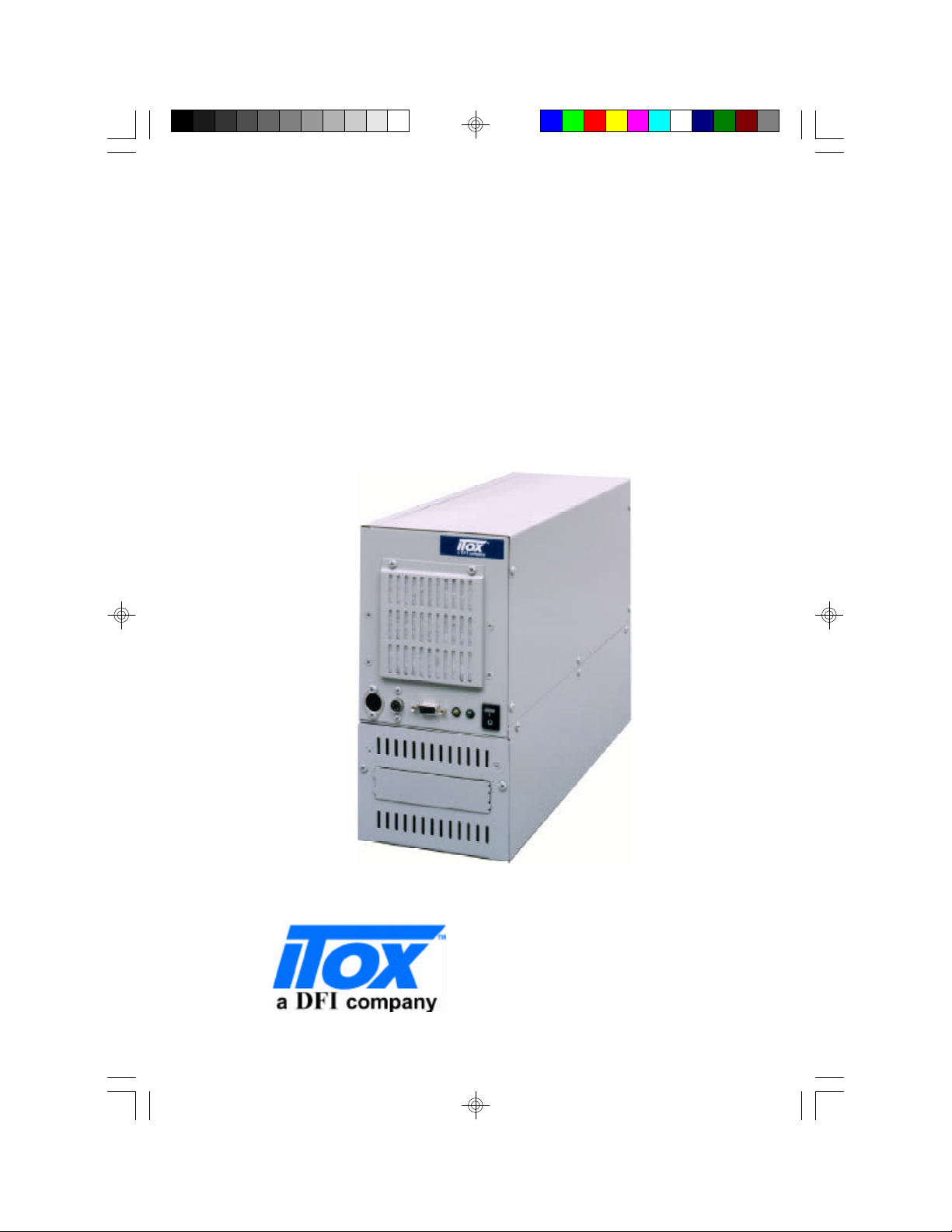
Tiger Star System
User’s Manual
Light Industrial Products...
http://www.itox.com
Page 2

ITOX, Inc.
8 Elkins Road
East Brunswick, NJ 08816
U.S.A.
(732) 390-2815
http://www.itox.com
DFI-USA
135 Main Avenue
Sacramento, CA 95838
U.S.A.
(916) 568-1234
http://www.dfiusa.com
DFI Computers Ltd.
Unit 1, Kangley BusinessCentre
Kangley Bridge Road
London, UK SE6 5AQ
(44-181) 776-5555
http://www.dfiuk.co.uk
DFI Germany
Julius-Faucher Str. 31
28307 Bremen
Germany
(49-421) 565-6811
[email protected]
Document No. : E-ML-001A
DFI Inc.
100 Huan-Ho St.
Hsi-Chih Town
Taipei Haien, Taiwan R.O.C.
(886-22) 694-2986
http://www.dfiweb.com
Printed in USA
Page 3

Copyright
This publication contains information that is protected by copyright.
No part of it may be reproduced in any form or by any means or used
to make any transformation/adaptation without the prior written permission from the copyright holders.
This publication is provided for informational purposes only. The
manufacturer makes no representations or warranties with respect to
the contents or use of this manual and specifically disclaims any express or implied warranties of merchantability or fitness for any particular purpose. The user will assume the entire risk of the use or the
results of the use of this document. Further, the manufacturer reserves
the right to revise this publication and make changes to its contents at
any time, without obligation to notify any person or entity of such
revisions or changes.
All Rights Reserved.
Trademarks
ITOX TM is a trademark of ITOX Inc. Microsoft® MS-DOS® is a registered trademark of Microsoft Corporation. IBM® is a registered trademark of International Business Machine Corporation. STPC® is a
registered trademarks of ST Microelectronics. DiskOnChip is a registered trademark of M-systems Inc.. Other trademarks and registered
trademarks of products appearing in this manual are the properties of
their respective holders.
Caution:
Danger of explosion if battery incorrectly replaced. Replace only with
the same or equivalent type recommended by the manufacturer. Dispose of used batteries according to the battery manufacturer’s instructions.
1
Page 4

FCC and DOC Statement on Class B
This equipment has been tested and found to comply with the lim-
its for a Class B digital device, pursuant to Part 15 of the FCC
rules. These limits are designed to provide reasonable protection
against harmful interference when the equipment is operated in a
residential installation. This equipment generates, uses and can radiate radio frequency energy and, if not installed and used in accordance with the instruction manual, may cause harmful interference to radio communications. However, there is no guarantee
that interference will not occur in a particular installation. If this
equipment does cause harmful interference to radio or television
reception, which can be determined by turning the equipment off
and on, the user is encouraged to try to correct the interference
by one or more of the following measures:
• Reorient or relocate the receiving antenna.
• Increase the separation between the equipment and the receiver.
• Connect the equipment into an outlet on a circuit different
from that to which the receiver is connected.
• Consult the dealer or an experienced radio TV technician for
help.
Notice:
1. The changes or modifications not expressly approved by the
party responsible for compliance could void the user's authority to operate the equipment.
2. Shielded interface cables must be used in order to comply with
the emission limits.
2
Page 5

Tiger Star Manual
Table of Contents
Chapter 1 - Introduction
Tiger Star System Concept ...........................................
Specifications...............................................................
System Configuration....................................................
Package Checklist........................................................
Chapter 2 - Hardware Installation and Setup
Removing the Access Cover.........................................
Installing Expansion Cards.............................................
Installing Disk Drives......................................................
Wall Mounting the Tiger Cub........................................
Installing SIMMs............................................................
Front View ..................................................................
Back View .................................................................
Chapter 3 - BIOS Setup Utility
The Basic Input/Output System......................................
Standard CMOS Setup..................................................
Advance CMOS Setup..................................................
Shadow Configuration...................................................
Chipset Features Setup.................................................
Power Management Setup...........................................
PCI/Plug and Play Configuration....................................
Peripheral Setup............................................................
Other Setup Options.....................................................
6
6
9
9
12
12
13
14
15
17
18
20
20
24
27
28
29
32
35
37
Appendix A - Board Layout
Connector/Jumper Setting Locations & Functions..........
Jumper Setting Functions.............................................
JP2 - CMOS Settings....................................................
JP4 - BIOS Settings.......................................................
JP5 - Msystem Address Select......................................
J11, J12 - Power and HDD LED.....................................
System Board Connector/Jumper Layout.......................
3
40
41
41
41
41
42
43
Page 6

Appendix B - Watchdog Timer
Using the Watchdog Timer............................................
Appendix C - Video Subsystem
Graphics Driver Installation..............................................
VGA Frame Buffer Size...................................................
Appendix D - Troubleshooting
Frequently Asked Questions ...........................................
Troubleshooting Checklist.. ............................................
Appendix E - Warranty
Warranty Terms.............................................................
Appendix F- Year 2000 Compliance
Year 2000 Statement....................................................
47
51
51
54
55
63
67
Index......................................................................
4
68
Page 7
CHAPTER
1
Introduction
Page 8
1
Tiger Star User’s Manual
Features and Specifications
Introduction
Tiger Star System Concept
The ITOX Tiger star uses state-of-the-art design to provide a compact,
low cost PC platform for Computer Telephony and other industrial
applications that require multiple, full length ISA/PCI interface cards. The
Tiger Star uses the highly integrated ST Microelectronics STPC microprocessor which combines all the functions normally found on a PC into
one powerful chip. The Tiger Star features full PC compatibility (including
keyboard, mouse, floppy disk, and video controller) in a very small
industrial case that doesn’t look like a PC.
The Tiger Star is designed for operation in light industrial environments. It
is packaged in a small industrial enclosure that can be mounted on a wall
or placed on a shelf or table. The STPC processor executes an enhanced
486 instruction set and is compatible with DOS, Windows 3.1, Windows
95/98, and Windows NT operating systems.
An on-board watchdog timer supports reliable operation in unattended
applications by restarting the system automatically if the software hangsup.
Specifications
The Tiger Star’s processor is soldered in place on the motherboard.
Consequently, the processor speed must be specified at the time of order.
Detailed Specifications
Processor ST Microelectronics STPC client
CPU Speed 66 MHz standard, 133 MHz optional
(Factory configured)
Cache 8 Kbyte integrated L1 write-back
(L2 cache subsystem is not supported)
6
Page 9

Introduction
Memory Size 8 Mbyte to 128 MB (0 memory in base system)
Memory Type/Slots 2 Fast Page or EDO 72 pin SIMM Sockets,
60/70 ns
BIOS AMI BIOS Ver. 1.2; Windows 95 PnP
compatible
Keyboard Connector AT – Mounted on Front Panel
Mouse Connector PS/2 – Mounted on Front Panel
Watchdog Timer Supports 8 set time intervals,
0.5/1/2/4/8/16/32/64 sec.
Video 64 bit Windows Accelerator up to 1280 x 1024
resolution; VGA Output
1
System Bus Clock 33 MHz
Real-Time Clock Standard; 32.768 KHz
PCI IDE Interface DMA Mode: DMA 33 support
DMA Transfer rate: 33 MB/sec
PIO Mode Transfer Rate: 16.6 MB/sec
Floppy Drive Supports 360k/720k/1.22 MB/1.44MB/2.8 MB
floppy drive
Disk Drive Bays Three 3.5” - One externally accessible
All disks mount in removable drive tray
Flash Disk Socket Supports optional M-system Disk-on-
Chip flash Disk up to 72MByte
7
Page 10
1
Tiger Star User’s Manual
Expansion Slots Three Slots total:
Two full-length, full-height , 16 bit ISA
One shared PCI/ISA
Bus Voltages:
ISA slots: +12 v +/- 10%, -12v +/- 10%,
+5v +/- 5%, -5v +/- 5%
PCI slot : +12 v +/- 10%, -12v +/- 10%, +5v +/- 5%
Input/Output Ports Parallel printer port, SPP/EPP/EPC compatible
` with IEEE 1284 specification
2 serial ports, (NS16550A compatible)
Board Size 13.25” (337 mm) x 4.875” (124 mm)
Power Supply 115 to 220 VAC switch selectable, 50/60 Hz
150 watts, with internal cooling fan; ATX &
micro ATX connector
Cooling Fans Motherboard/expansion slot area cooled by
3.2” (80 mm) Dia fan with air filter
Additional 2.4” (61 mm) Dia fan in power
supply
Weight 12 pounds (5.5 kg) [not including disk drives]
Dimensions 15.5” (394 mm) x 5.25” (133 mm) x 10.5”(266 mm)
Standard Color Light Industrial Gray (Pantone 429U)
Certifications UL, FCC, CSA, CE
Other Features Voltage/Fan/Temperature Monitor
Operating Systems DOS, Windows 3.1, 95/98/NT, and Linux compatible
8
Page 11

Introduction
1
Operating Temp. O
Operating Temp. -20
o
to 45O C ( 32
o
to +70O C (-4
o
to 113o F)
o
to 158o F)
Humidity 10% to 90% relative humidity, Non condensing
Options Rack mount adapter
System Configuration
The Tiger Star is an industrial computer intended for light industrial
applications. The base confirguration includes an all-steel case, power
supply, motherboard with three expansion slots, and a factory installed
processor. The standard Tiger Star is configured with a 66 MHz processor. A 133 MHz processor is available as a factory installed option and
must be specified at the time the system is ordered.
The system accommodates 8 to 128MB of fast page or EDO DRAM which
is sold separately. The system supports a keyboard, mouse and VGA
display which are also sold separately.
Several disk storage options are available and are not included in the
basic configuration. Available options include hard drives of various
capacities, 3 ½” floppy disk and flash disk in capacities up to 72 MB.
The flash disk chip mounts in a socket provided on the motherboard.
Hard drives are mounted in a removable disk tray for easy assembly. The
removable disk tray feature also allows field application software upgrades to be performed by shipping the user a preloaded hard drive
mounted in a spare disk tray.
Optically available operating systems include Microsoft MS DOS 6.22,
Windows 95, Windows 98, and Windows NT. Contact ITOX concerning
compatibly with other operating systems.
9
Page 12
1
Tiger Star User’s Manual
Package Checklist
The Tiger Star system package contains the following items:
• One Tiger Star complete with motherboard and power supply
• One Power Cable
• Driver software (floppy disk)
• One Manual
Optional items such as disk drives may also be enclosed in the
package. Check your packing list carefully.
If any of these items are missing or damaged, please contact your
supplier for assistance.
10
Page 13
CHAPTER
2
Hardware Installation
and
Setup
Page 14
2
Tiger Star User’s Manual
II. Hardware Installation and Set Up
Caution: Always unplug the AC power cord from the Tiger Star before
opening the cabinet to prevent possible contact with the rotating fan
blade or hazardous voltage. The Tiger Star is designed so that all high
voltage components remain enclosed in the lower portion of the cabinet
when the access panel is removed. However, contact with potentially
hazardous voltage is possible if tools or screws enter the lower portion
of the case through the cable or cooling holes.
Set Input Voltage Selector Switch
The Tiger Star is equipped with a dual range power supply for operation
with AC input voltage from 100 to 240 VAC at 50/60 Mz. Set the AC
voltage selector switch on the rear panel of the Tiger Cub to the appropriate postion based table below.
AC Voltage Switch Settings
Normal Input Voltage Switch Setting
100-120 Vac 115
200-240 Vac 230
Removing the Access Cover
Remove the six screws on the side of the Tiger Star cabinet (five on one
side & one on the top back middle side) and remove the access cover to
install expansion cards and set jumpers. The Tiger Star is supplied with a
retaining bracket to hold expansion cards in place. Remove the screw at
each end of the bracket and remove the bracket to provide access for
installing expansion cards.
Installing Expansion Cards
Warning: Electrostatic discharge (ESD) can damage your
processor, disk drives, add-in boards, and other components.
Perform the instruction procedures described at an ESD
workstation only. If such a station is not available, you
can provide some ESD protection by wearing an antistatic
wrist strap and attaching it to a metal part of the system
12
Page 15

Hardware Installation and Setup
chassis. If a wrist strap is unavailable, establish and maintain
contact with the system chassis throughout any procedures
requiring ESD protection.
The Tiger Star is designed to accept three full length, full height expansion cards utilizing the 16 bit ISA and PCI/ISA shared interface connectors. Remove the appropriate number of filler plates from the back of the
unit, install the cards in the normal manner, and secure them in place with
the screw previously used to hold the filler plate in place.
The retaining bracket should be replaced after the cards have been
installed. Install the screws which hold the black rubber pads into the
bracket so they hold the expansion cards firmly in place. The access
cover should be replaced after the jumpers have been set. See appendix
A for the correct jumper setting for your system configuration.
Installing Disk Drives
The Tiger Star uses a removable disk tray for quick and easy mounting of
hard (and floppy) disk drives.
1. Remove the drive tray from the front panel of the Tiger Star.
It is not necessary to remove the access cover to install disk drives.
Verify that the Tiger Star power cord is disconnected from the AC voltage
source. Remove the two phillips head screws located closest to the
outside edges of the lower portion of the front panel. Then
slide the drive tray out the front of the unit.
2
2. Install the drive(s) in the drive tray.
The drive tray includes slots for mounting up to three 3 ½ “ disk drives.
Select the set of slots you want to use and mount the drive according to
the manufacturer’s instructions. The center drive position has a knockout section that can be removed to provide exterior access to the drive.
This position is typically reserved for floppy drives. Remove the knockout before installing any of the drives if a floppy drive will be installed.
3. Connect the data and power cables.
Reach into the lower portion of the Tiger Star case through the opening
where the drive tray mounts. Gently guide the power cable and ribbontype data cable through the opening so they can be connected to the
13
Page 16
2
Tiger Star User’s Manual
disk drive. The connectors are keyed for proper attachment; make sure
that the connectors are attached to the drive in the proper orientation.
4. Install the drive tray back into the Tiger Star case.
Slide the drive tray back into the case; guide the cables into the opening
while doing this to keep them away from any sharp edges and insure they
remain fully engaged. Secure the drive tray in place with the two screws
removed in step 1 above.
Wall Mounting the Tiger Star
The Tiger Star is designed to be placed on a shelf, table or other flat
surface, or wall mounted. Rubber feet are provided for table top operation.
Four key-hole shaped mounting holes are provided in the side of the
Tiger Star for wall mounting. Use of all four wall mounting points is
recommended and will result in the most secure installation; at least one
of the front brackets and one of the rear brackets must be used to provide
adequate support. A template for installing the mounting screws in the
wall is provided in the Tiger Star box.
The Tiger Star mountings have a protective back plate that prevents
narrow objects from entering the case. The mounting holes are designed
to slip over the heads of screws mounted in the wall or other vertical
surface upon which the Tiger Star is to be mounted. The holes are
designed for ¼ inch (6 mm) pan head screws, but can be used with any
screws with a head diameter between 0.35 inch (9 mm) and 0.55 inch (14
mm) and a maximum head height of 0.2 inch (5 mm). The screws should be
installed to allow a clearance of 1/16 inch (1.5 mm) under the screw head
to provide clearance for the thickness of the mounting bracket.
Once the screws are installed in the wall to the proper depth, place the
mounting holes over the screw heads and then slide the Tiger Star down
to secure it in place. It can be removed for servicing by sliding the unit up
and lifting the unit off the screw heads.
14
Page 17
Hardware Installation and Setup
Installing Memory
SIMM
The SIMM sockets are divided into two banks on the Itox- Star board,
Bank 0 and Bank 1. Each bank consists of 1 SIMM socket.
Your board supports 8MB to 128MB of DRAM memory using two 72-pin
SIMM modules.
You must populate both banks with two single-sided or double sided 72
pin SIMM (Single In-line Memory) modules
(fast page or EDO DRAM 60/70 ns 5V). Make sure you insert the same
type and MB size into each bank.
The following table summarizes the bank locations and modules needed
for the corresponding memory sizes.
ITOX-STAR System Memory:
TOTAL
MEMORY SIMM1 SIMM2
8MB 4MB 4MB
2
16MB 8MB 8MB
32MB 16MB 16MB
64MB 32MB 32MB
128MB 64MB 64MB
The STPC has a VGA display interface built in, so some of the SIMM
memory will be subtracted from the main system’s total available memory.
To select the VGA frame buffer size select the Advanced Chipset Setup
screen during BIOS setup (see page 28). The default seeting is 512KB,
but for high resolution viewing it is recommended that 1024 KB be
selected.
15
Page 18
2
Tiger Star User’s Manual
Installing a SIM Module
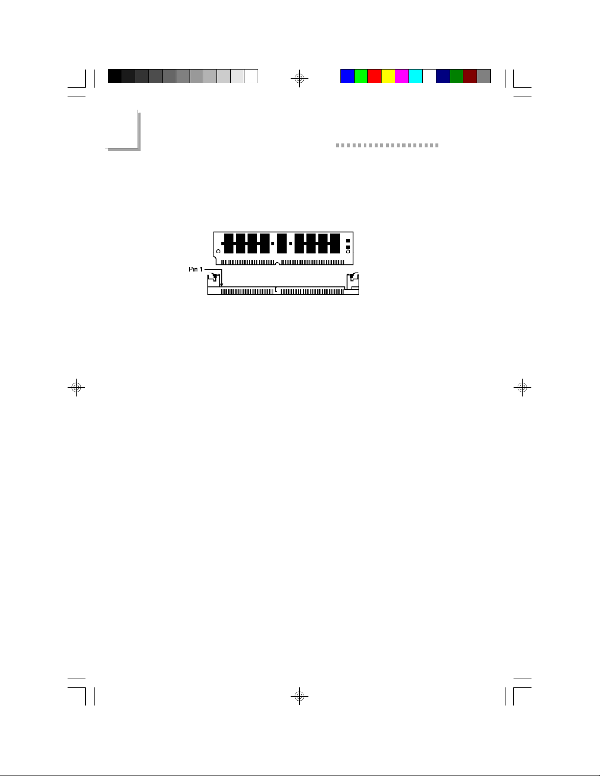
A SIM module simply snaps into a socket on the system board. Pin 1
of the SIM module must correspond with Pin 1 of the socket.
1. Load the outside socket which faces the keyboard connector
first.
2. Position the SIMM above the socket with the “notch” in the
module aligned with the “key” on the socket.
3. Seat the module at a 45° angle into the bank. Make sure it is
completely seated. Tilt the module upright until it locks in
place in the socket.
4. Repeat the procedure for the second socket
16
Page 19
Hardware Installation and Setup
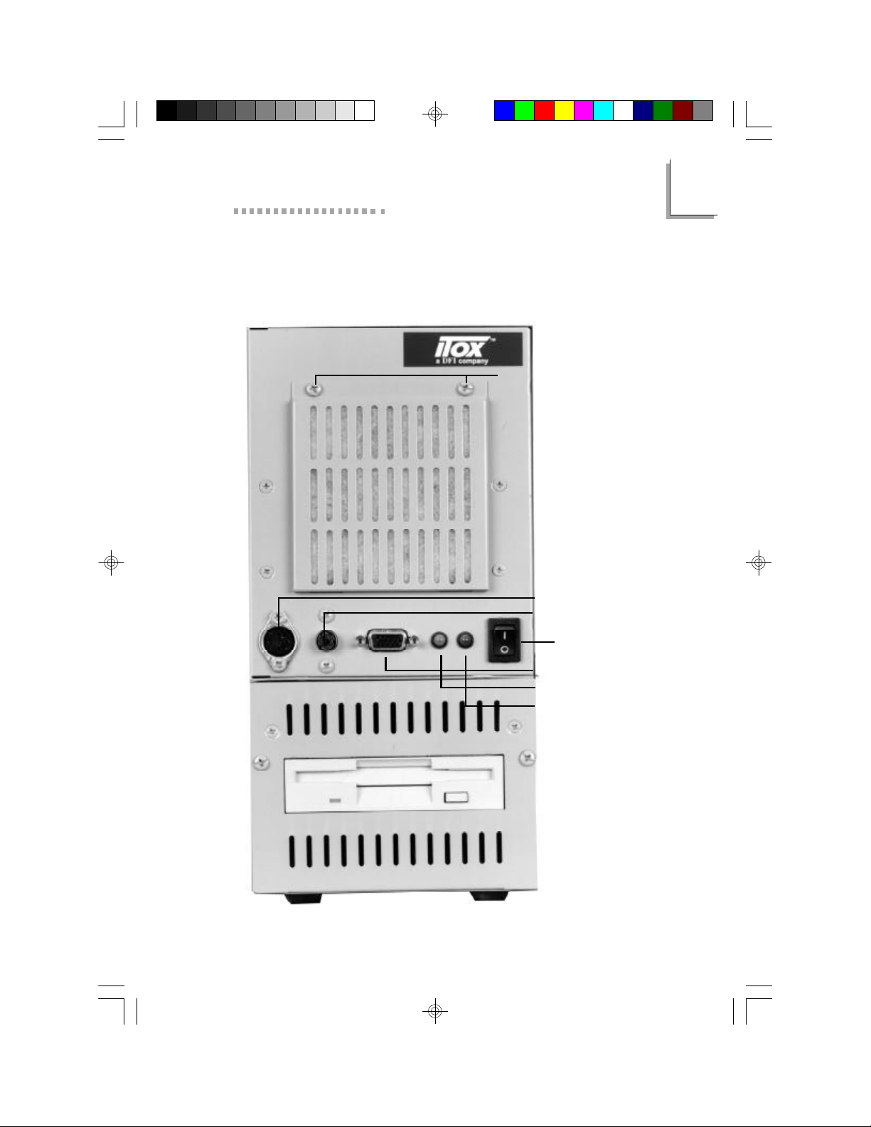
Front View of Tiger Star System
Connectors, Switches and Indicators
Air Filter Access Screws
AT Keyboard Connector
PS Type Mouse Connector
2
17
Power Switch
VGA Display Connector
HD Active LED (Yellow)
Power LED (Green)
Page 20
2
Tiger Star User’s Manual
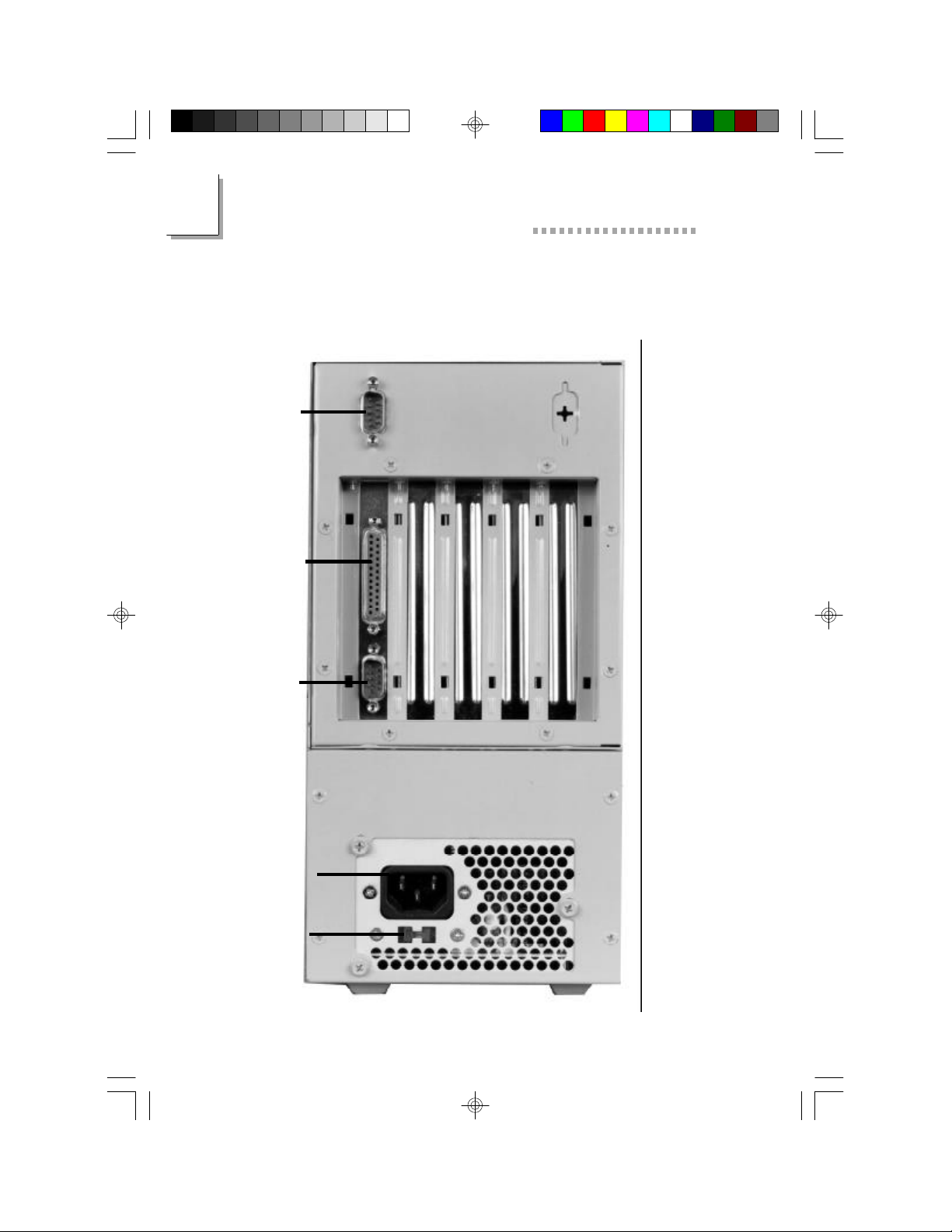
COM1 Port
Parallel Port
(LPT1)
Back View of Tiger Star System
Connectors, Switches and Ports
COM2 Port
Power Cord
Connector
AC Voltage
(115v/230v)
Selection
Switch
18
Page 21
CHAPTER
3
BIOS Setup Utility
Page 22
3
Tiger Star User’s Manual
The Basic Input/Output System
The Basic Input/Output System (BIOS) is a program that takes care of
the basic level of communication between the processor and peripherals.
In addition, the BIOS also has support for various advanced features
found in this system board. This chapter explains the Setup Utility for the
AMI BIOS. For clarity, the selected or available selections are printed in
italics in this section.
After you power up your system, the BIOS message appears on your
screen and the memory count begins. After the memory test, the following message will appear on the screen:
Press DEL to enter setup
If the message disappears before you respond, restart your system or
press the Reset button. You may also restart the system by pressing the
<Ctrl> <Alt> and <Del> keys simultaneously.
When you press <Del>, the setup screen will appear.
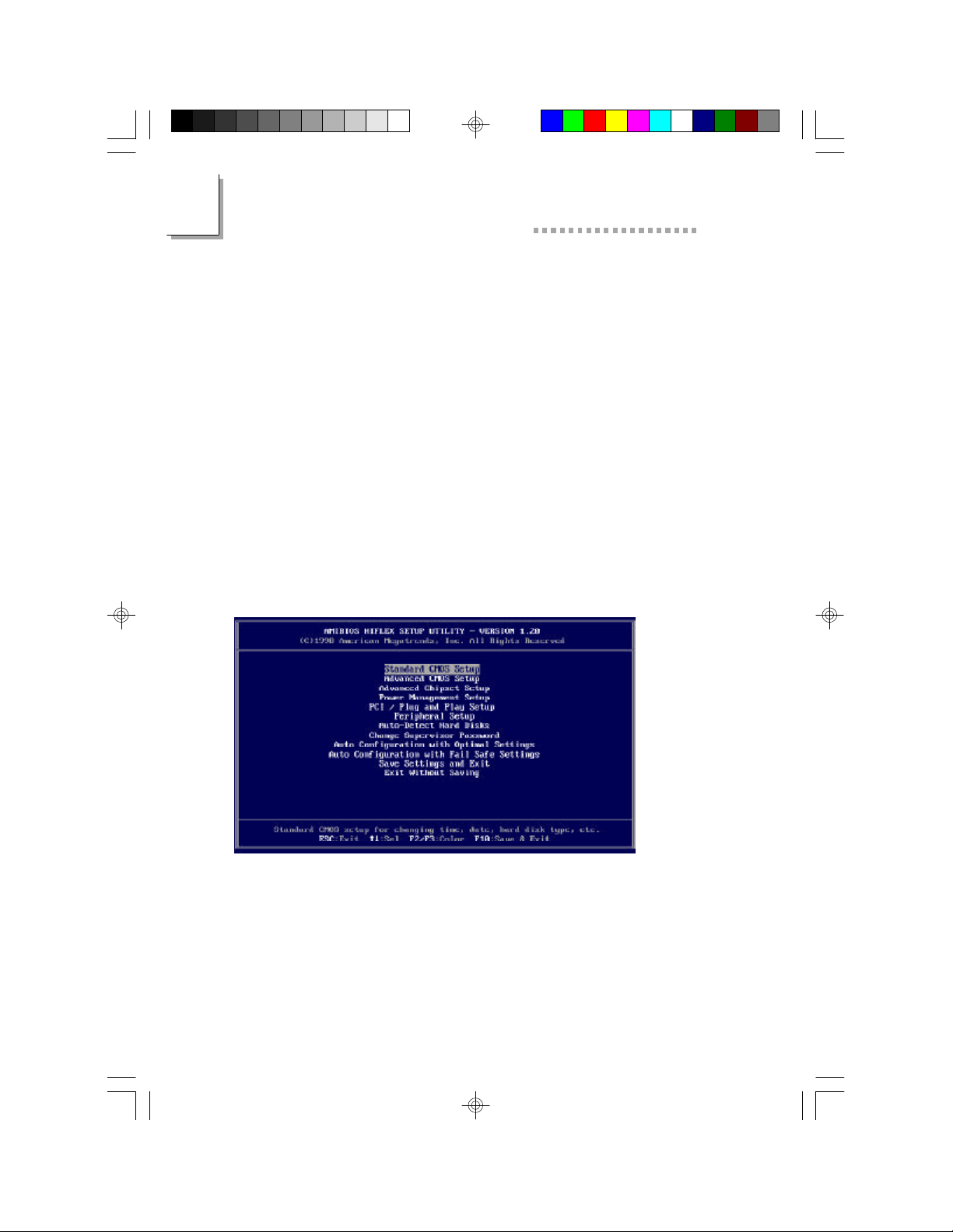
Standard CMOS Setup
Use the arrow keys to highlight Standard CMOS Setup and press
<Enter>. A screen similar to the one on the next page will appear.
20
Page 23
BIOS Setup Utility
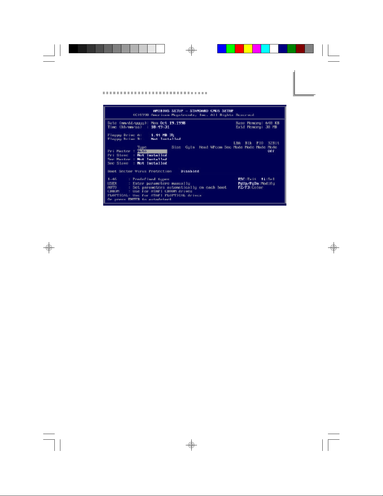
The settings on the screen are for reference only. Your
version may not be identical to this one.
Date
The date format is <day>, <month>, <date>, <year>. Day displays a day,
from Sunday to Saturday. Month displays the month, from January to
December. Date displays the date, from 1 to 31. Year displays the year,
from 1994 to 2079.
3
Time
The time format is <hour>, <minute>, <second>. The time is based on the
24-hour military-time clock. For example, 1 pm. is 13:00:00. Hour displays
hours from 00 to 23. Minute displays minutes from 00 to 59. Second displays seconds from 00 to 59.
Drive A and Drive B
These categories identify the types of floppy disk drives installed. The
options for drive A and B are:
None No floppy drive is installed
360K, 5-1/4 in. Standard drive; 360KB capacity
1.2M, 5-1/4 in. AT-type high-density drive; 1.2MB
capacity
720K, 3-1/2 in. Double-sided drive; 720KB capacity
1.44M, 3-1/2 in. Double-sided drive; 1.44MB capacity
2.88M, 3-1/2 in. Double-sided drive; 2.88MB capacity
21
Page 24

3
Tiger Star User’s Manual
Note:
Choosing an incorrect type might cause your system to
format the floppy disk improperly and you may not be
able to access your data.
Primary Master, Primary Slave, Secondary Master and
Secondary Slave
These categories allow you to enter the appropriate specifications for the type of hard disk drive(s) installed in your system. There are 46 predefined types for hard drives. Type 1 to
Type 46 are predefined. Type User is user-definable.
Press <PgUp> or <PgDn> to select a numbered hard disk
type or type the number and press <Enter>. The hard
disk will not work properly if you enter improper information for this category.
You can use Type User to define your own drive type
manually. This information should be included in the
documentation from your hard disk vendor.
If the controller of the HDD interface is SCSI, you must
select None.
Auto is the standard default for Primary Master meaning
the BIOS will auto-detect the HDD drive at the POST stage
and show the IDE parameters for the HDD drive. If a hard
disk has not been installed, select Not Installed and press
<Enter>.
Select ARMD if configuring an ATAPI drive. AMIBIOS displays the drive parameters.
ENTERING DRIVE PARAMETERS
You can also enter the hard disk drive parameters. The drive
parameters are:
22
Page 25

BIOS Setup Utility
Parameter Description
Type The number for a drive with certain identification
parameters.
Cylinders The number of cylinders in the disk drive.
Heads The number of heads.
3
Write
Sectors
The size of a sector gets progressively smaller as the
track diameter diminishes. Yet each sector must still
hold 512 bytes. Write precompensation circuitry on
the hard disk compensates for the physical difference
in sector size by boosting the write current for
sectors on inner tracks. This parameter is the track
number where write precompensation begins.
The number of sectors per track. MFM drives have 17
sectors per track. RLL drives have 26 sectors per track.
ESDI drives have 34 sectors per track. SCSI and IDE
drives have more sectors per track.
LBA, Blk (Block) and PIO (Programmed IO) Mode
With Auto selected these will remain blank.
32 Bit Mode
The default is Off. Select On if you know your hard disk supports it to
increase performance.
Memory
The base memory size, extended memory size and the other memory size
cannot be altered; your computer automatically detects and displays
them.
Base Memory
The POST will determine the amount of base (or conventional) memory
installed in the system. The value of the base memory is typically 640K.
23
Page 26

3
Tiger Star User’s Manual
Extended Memory
The BIOS determines how much extended memory is present during the
POST. This is the amount of memory located above 1MB in the CPU’s
memory address map.
Boot Sector Virus Protection
Disabled is the default setting. Choose Enabled to enable boot sector
protection. AMI BIOS will display a warning when any program (or virus)
issues a Disk Format command or attempts to write to the boot sector of
the hard disk drive. When enabled is selected the following appears when
a write is attempted to the boot sector. You may have to type N several
times to prevent the boot sector write.
Boot Sector Write ! ! !
Possible VIRUS: Continue (Y/N)? _
The following appears after any attempts to format any cylinder, head, or
sector of any hard disk drive via the BIOS INT 13 Hard Disk Drive
Service:
Format ! ! !
Possible VIRUS: Continue (Y/N)?_
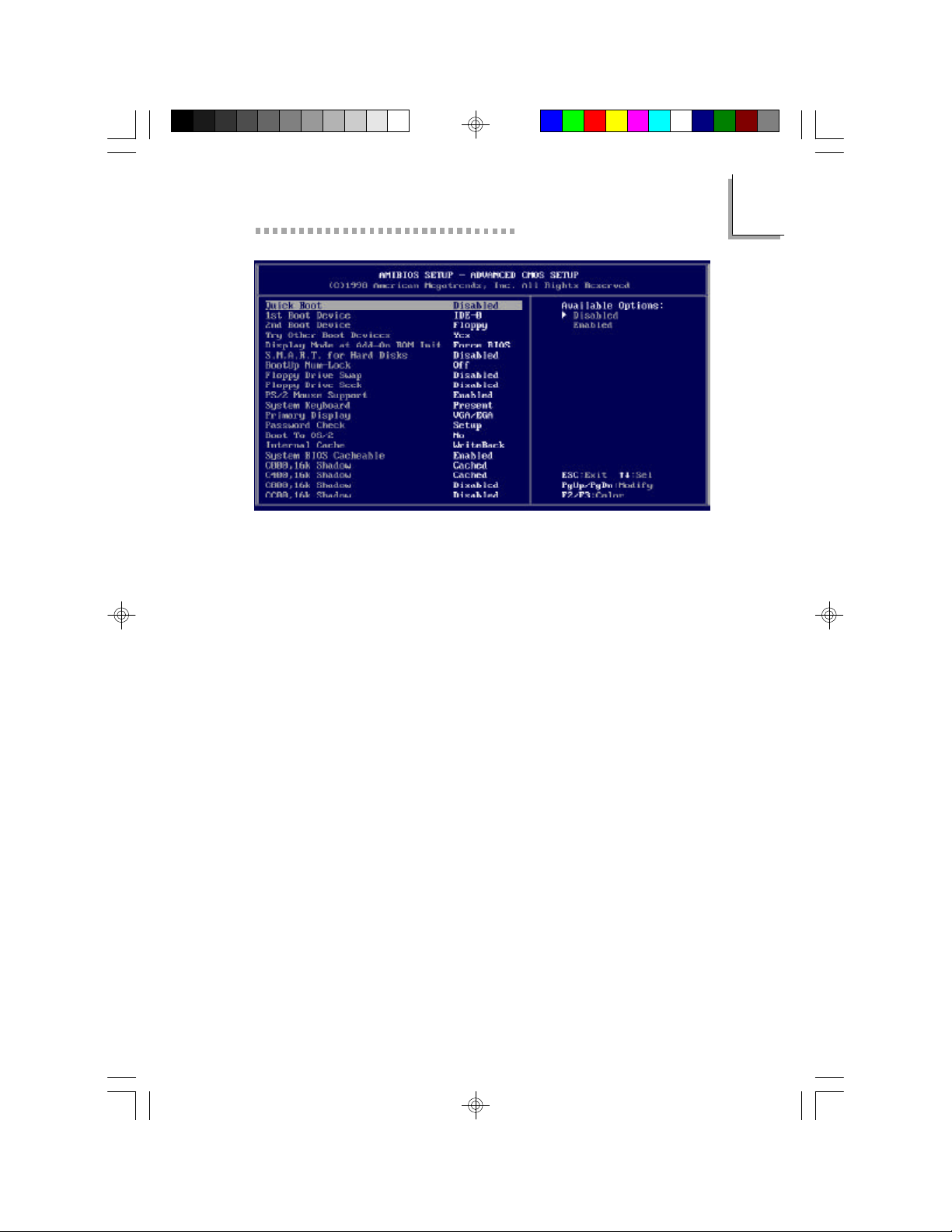
Advanced CMOS Setup
The advanced CMOS setup allows you to configure your system for basic operation. Some entries are defaults required by the system board,
while others, if enabled, will improve the performance of your system or
let you set some features according to your preference.
24
Page 27
BIOS Setup Utility
Quick Boot
Disabled is the default setting. Selecting Enabled will reduce the amount
of time to run the power on self test (POST), but may result in important
steps being skipped.
1st Boot Device
This option sets the type of first boot device drives that the AMI BIOS
attempts to boot from after the POST completes. Settings include Disa-
bled, Network, Floppy, ARMD-FDD, ARMD-HDD, SCSI, CDROM, IDE0(HDD), IDE-1, IDE-2, or IDE-3. The Optimal and Fail-Safe default set-
ting is IDE-0.
3
2nd Boot Device
This option sets the type of device 2nd and 3rd boot drives that the
AMIBIOS attempts to boot from after the POST completes. Settings include Disabled, Floppy, ARMD-FDD, ARMD-HDD, SCSI, CDROM, IDE-
0(HDD), IDE-1,IDE-2, or IDE-3. The Optimal and Fail-Safe default setting is Floppy.
Try other Boot Devices
The standard default setting is YES which instructs AMI BIOS to boot
from any other drive in the system if it cannot find a boot drive among
the drives specified in the 1st boot device or 2nd boot device.
25
Page 28

3
Tiger Star User’s Manual
Display Mode at Add-On ROM Init:
Use this opition only if you are using a third party video card. The settings are Force BIOS or Keep Current. Force BIOS is the default setting.
Force BIOS copies the VGA BIOS from the VGA add-on card.
Keep current is a testing feature used to test the BIOS in DOS mode.
We recommend selecting Force BIOS.
S.M.A.R.T. for Hard Disks:
The system board supports ATA-3 or later hard drives which contain the
S.M.A.R.T (Self-Monitoring, Analysis and Reporting Technology).
S.M.A.R.T. allows the drive to provide sufficient notice and time for the
system or user to backup data prior to the drive’s failure. Disabled is the
default. If you are using hard drives that support S.M.A.R.T., set this
field to Enabled.
Bootup Num-Lock: On is the default setting.
Floppy Drive Swap:
Disabled is the default setting. The system will boot from drive A.
Floppy Drive Seek: Enabled is the default setting.
PS/2 Mouse Support: Enabled is the default setting.
System Keyboard: Present is the default setting. This option does
not specify if a keyboard is attached to the computer. Instead, it specifies if error messages are displayed if a keyboard is not attached. This
allows you to configure workstations with no keyboards. The available
setting are Absent or Present.
Primary Display: This option configures the type of monitor attached to the computer. Although secondary monitors are supported, you
do not have to select the type in Setup. VGA/EGA is the default setting.
VGA/EGA
Enhanced Graphics Adapter/Video Graphics Array. For EGA, VGA, SVGA
and PGA monitor adapters.
CGA 40x25
Color Graphics Adapter. Power up in 40-column mode.
CGA 80x25
Color Graphics Adapter. Power up in 80-column mode.
26
Page 29

BIOS Setup Utility
Mono
Monochrome adapter. Includes high resolution monochrome
adapters.
Password Check:
This option enables the password check everytime the system boots or the
end user runs Setup. If Always is chosen, a user password prompt will
appear every time the computer is turned on. Setup is the default setting
and the password prompt appears if the BIOS is executed.
Boot to OS/2: The default setting is No. The Tiger Star does not
support OS/2.
Internal Cache
This category speeds up the memory access. The default setting is
Enabled.
System BIOS Cacheable
When set to Enabled, the contents of the F0000h system memory segment
can be read from or written to cache memory. The contents of this memory
segment are always copied from the BIOS ROM to system RAM for faster
execution. The settings are Enabled or Disabled. The default setting is
Enabled.
3
Video Shadow Default Setting
C000,16k Shadow Cached
C400,16k Shadow Cached
C800,16k Shadow Disabled
CC00,16k Shadow Disabled
D000,16k Shadow Disabled
D400,16k Shadow Disabled
D800, 16k Shadow Disabled
DC00, 16k Shadow Disabled
27
Page 30
3
Tiger Star User’s Manual
These options enable shadowing of the contents of the ROM area in the
option title.
Setting Description
Enabled The contents of the ROM area are written to the
corresponding address in RAM for faster execution.
Cached The contents of the ROM area are written to the
corresponding RAM address and can be read from
or written to cache memory.
Disabled The ROM is not copied to RAM. The contents of the
video ROM cannot be read from or written to cache
memory.
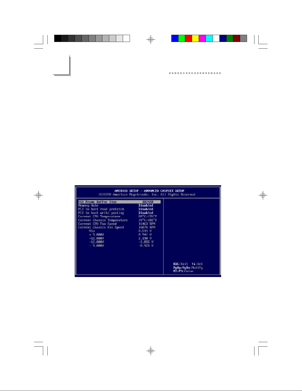
Advanced Chipset Setup
The settings on the screen are for reference only. Your version may not be identical to this one.
This section gives you functions to configure the system based on the
specific features of the chipset. The chipset manages bus speeds and
access to system memory resources.
28
Page 31
BIOS Setup Utility
It also coordinates communications between the conventional ISA bus
and the PCI bus. These items should not be altered unless necessary.
Depending on your add-in boards, you may not or should not enable
some of those features. The default settings have been chosen because
they provide the best operating conditions for your system. The only
time you might consider making any changes would be if you discovered
some incompatibility or that data was being lost while using your system.
VGA Frame Buffer Size
This is the amount of memory which is allocated to the built in VGA (see
appendix C). The default setting is 512 KB. For high resolution view-
ing it is recommended that 1024 KB be selected. This amount of memory
will be subtracted from the main system total available memory. The maxi-
mum VGA buffer size is 4096 KB.
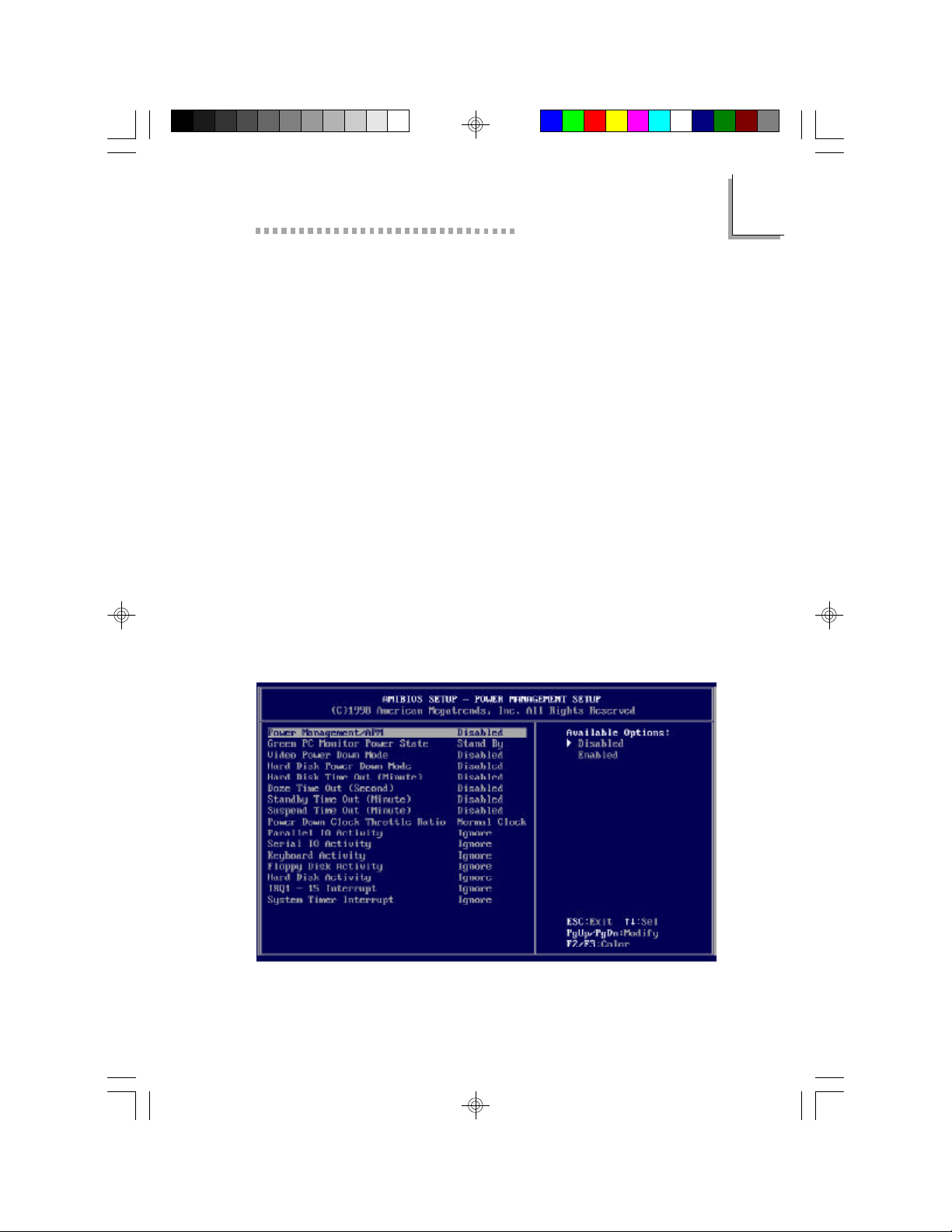
Power Management Setup
The Power Management Setup allows you to configure your system to
most effectively save energy. If you like to use the soft power down feature of Windows 95/98, you must enable the Power Management as described below.
3
The settings on the screen are for reference only. Your version may not
be identical to this one.
29
Page 32

3
Tiger Star User’s Manual
Power Management/APM
Set this option to Enabled to enable the chipset power management and
APM (Advanced Power Management) features. The settings are Enabled
or Disabled. The default setting is Disabled.
Green PC Monitor Power State
This option specifies the power state that the green PC-compliant video
monitor enters when the BIOS places it in a power saving state after the
specified period of display inactivity has expired. The settings are
Standby, Suspend, or Off. The default setting is Disabled.
Video Power Down Mode
This option specifies the power state that the video subsystem enters
when the BIOS places it in a power saving state after the specified period
of display inactivity has expired. The settings are Standby, Suspend or
Disabled. The default setting is Disabled.
Hard Disk Power Down Mode
This option specifies the power conserving state that the hard disk drive
enters after the specified period of hard drive inactivity has expired. The
settings are Disabled, Standby, or Suspend. The default setting is
Disabled.
Hard Disk Timeout (Minute)
This option specifies the length of a period of hard disk drive
inactivity. When this length of time expires, the computer enters powerconserving state specified in the Hard Disk Power Down Mode option.
The settings are Disabled, 1 min. (minute), 2 min, 3 min., 4 min., 5 min., 6
min, 7 min., 8 min., 9 min., 10 min., 11 min., 12 min., 13 min, or 14 min.
The default setting is Disabled.
Standby Time Out (Minute)
This option specifies the length of a period of system inactivity while in
Full power on state. When this length of time expires, the computer enters
Standby power state. The settings are Disabled, 4 min, 8 min, up to and
including 508 minutes, in increments of 4 minutes. The default setting is
Disabled.
30
Page 33

BIOS Setup Utility
Suspend Timeout
This option specifies the length of a period of system inactivity while in
Standby state. When this length of time expires, the computer enters
Suspend power state. The settings are Disabled, 4 min, 8 min, up to and
including 508 minutes, in increments of 4 minutes. The default setting is
Disabled.
3
31
Page 34
3
Tiger Star User’s Manual
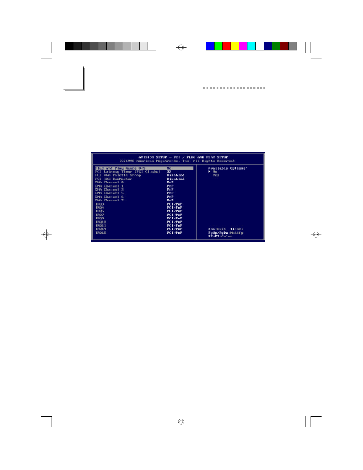
PCI/Plug and Play Configuration
This section describes configuring the PCI bus system. It covers some
very technical items and it is strongly recommended that only experienced
users should make any changes to the default settings.
The settings on the screen are for reference only. Your version
Plug and Play Aware OS
This category is used to enable or disable Plug and Play with your operating system.
Yes Select this option when you need Windows 95 to
detect the Plug and Play devices automatically.
No Select this option when you need the ability to change
IRQ settings that are selected by the plug and play
process. We recommend that you select this option
(default).
PCI Latency Timer
This option specifies the latency timings (in PCI clocks) for devices
installed in the PCI slots. The settings are 32, 64, 96, 128, 160, 192, 224,
or 248. The Optimal default settings is 32. The Fail-Safe default setting is
64.
may not be identical to this one.
32
Page 35

BIOS Setup Utility
PCI VGA Palette Snoop
When this option is set to Enabled, multiple VGA devices operating on
different buses can handle data from the CPU on each set of palette
registers on every video device. Bit 5 of the command register in the PCI
device configuration space is the VGA Palette Snoop bit (0 is disabled).
For example: if there are two VGA devices in the computer (one PCI and
one ISA) and the VGA Palette Snoop bit is:
Snoop Bit Action
Disabled Data read and written by the CPU is only directed
to the PCI VGA device's palette registers.
Enabled Data read and written by the CPU is directed to
the both the PCIVGA device palette registers and
the ISA VGA device palette registers, and the
palette registers of both devices can be identical.
This option must be set to Enabled if an ISA adapter card installed in
the system uses VGA palette snooping.
The Optimal and Fail-Safe default settings are Disabled.
PCI IDE BusMaster
Select Enabled to specify that the IDE controller on the PCI local bus
includes a bus mastering capability. The settings are Enabled or Disabled. The Optimal and Fail-Safe default settings are Disabled.
3
DMA Channel Setup
DMA Channel 0
DMA Channel 1
DMA Channel 3
DMA Channel 5
DMA Channel 6
DMA Channel 7
These options allow you to specify the bus type used by each DMA
channel. The settings are PnP or ISA. The Optimal and Fail-Safe default
settings are PnP.
33
Page 36

3
Tiger Star User’s Manual
AVAILABLE IRQ’s
IRQ3
IRQ4
IRQ5
IRQ7
IRQ9
IRQ10
IRQ11
IRQ14
IRQ15
These options specify the bus on which the specified IRQ line is used.
These options allow you to reserve IRQs for legacy ISA adapter cards.
They determine if the BIOS should remove an IRQ from the pool of
available IRQs passed to devices that are configurable by the system
BIOS.
The settings are ISA, PnP, PCI/PnP, or PCI. The Optimal and Fail-Safe
default settings are PCI/PnP.
If more IRQs must be removed from the pool, the end user can use these
options to reserve the IRQ by assigning an ISA setting to it. Onboard I/O
is configured by the BIOS. All IRQs used by onboard I/O are configured
as PCI, PnP, or PCI/PnP. IRQ14 and 15 will not be available if the onboard
Triton 2 PCI IDE is enabled.
If all IRQs are set to ISA and IRQ14 and 15 are allocated to the onboard
PCI IDE, IRQ9 will still be available for PCI and PnP devices, because at
least one IRQ must be available for PCI and PnP devices.
34
Page 37
BIOS Setup Utility
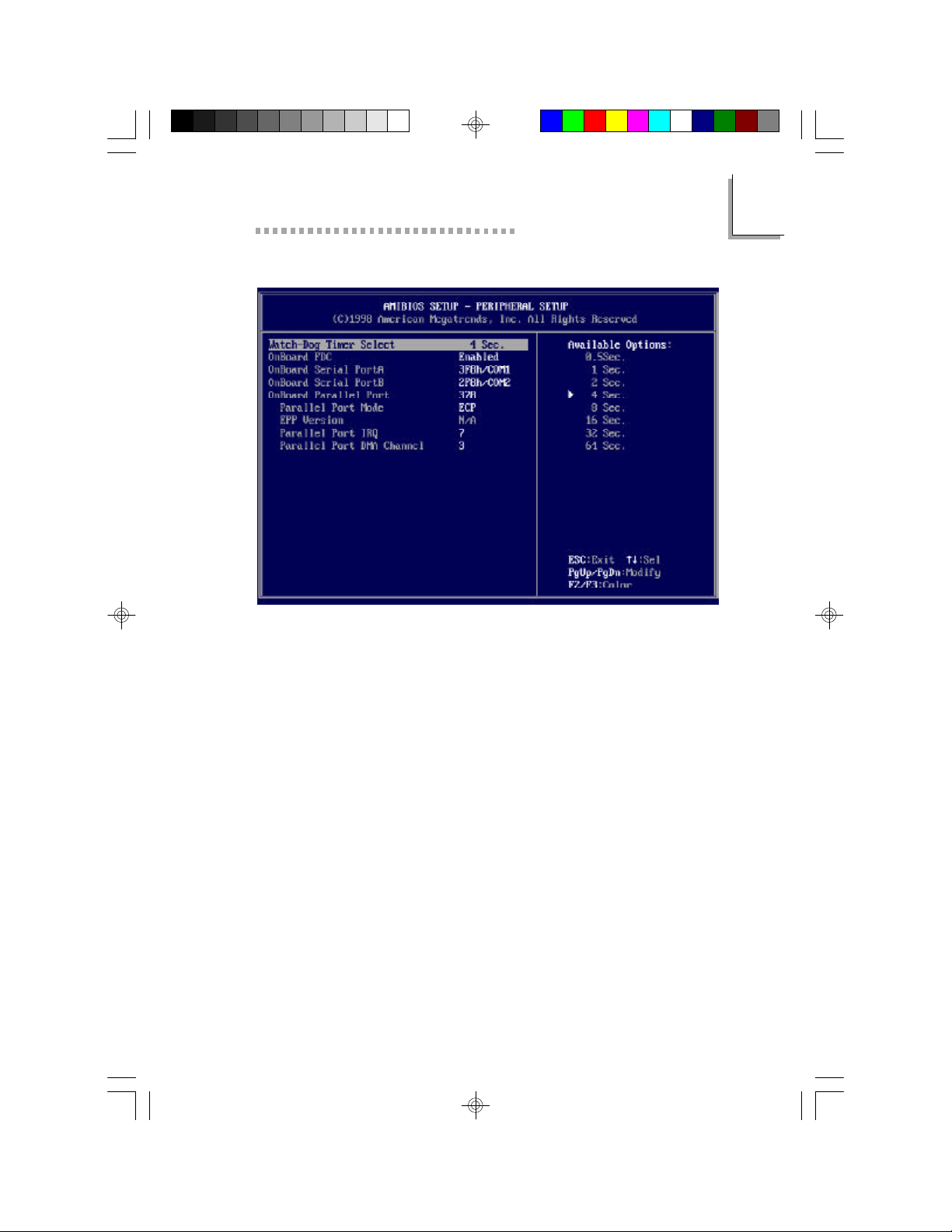
Peripheral Setup
The settings on the screen are for reference only. Your version may not
be identical to this one.
Watchdog Timer
3
The system board supports the Watchdog Timer function allowing your
application to regularly reset the system at the set time interval. If the system hangs or fails to function, it will reset at the set time interval so that
your system will restart. You may set the time interval in 0.5, 1, 2, 4, 8,
16, 32 or 64 sec.
The default is 4 sec.
Refer to Appendix B for instructions on using the Watchdog Timer func-
tion.
OnBoard FDC
Set this option to Enabled to use the floppy drive controller on the
motherboard. The settings are Auto (AMI BIOS automatically determines
if the floppy controller should be enabled), Enabled, or Disabled.
The Optimal default setting is Enabled.
The Fail-Safe default setting is Auto.
35
Page 38

3
Tiger Star User’s Manual
OnBoard Serial PortA and PortB
These options specify the base I/O port address of the built-in serial
ports. The settings are Auto (the BIOS automatically determines the correct base I/O port addresses), Disabled, 3F8h/COM1, 2F8h/COM2, 3E8h/
COM3, or 2E8h/COM4.
The Optimal default setting is 3F8h/COM1 for Serial PortA.
The Optimal default setting is2F8h/COM2 for Serial PortB.
The Fail-Safe default settings are Auto.
OnBoard Parallel Port
This option specifies the base I/O port address of the built-in parallel port.
The settings are Auto (the BIOS automatically determines the correct base
I/O port address), Disabled, 378h, 278h, or 3BCh.
The Optimal default setting is 378h.
The Fail-Safe default setting is Auto.
Parallel Port Mode
This option specifies the parallel port mode.
The Optimal default setting is ECP.
The Fail-Safe default setting is Normal.
The settings are:
Setting Description
Normal The normal parallel port mode is send only (not bidirectional).
Bi-Dir Use this setting to support bidirectional transfers on the
parallel port.
EPP The parallel port can be used with devices that adhere to the
Enhanced Parallel Port (EPP) specification. EPP uses the ex
isting parallel port’s signals to provide asymmetric bidirectional data transfer driven by the host device.
ECP The parallel port can be used with devices that adhere to the
Extended Capabilities Port (ECP) specification. ECP uses the
DMA protocol to achieve data transfer rates up to 2.5 MB
per second. ECP provides symmetric bidirectional communication.
36
Page 39

BIOS Setup Utility
EPP Version
This option specifies the Enhanced Parallel Port specification version
number that is used if the Parallel Port Mode option is set to EPP. It can
only be selected if the Parallel Port Mode option is set to EPP.
The settings are 1.7 or 1.9. There are no Optimal and Fail-Safe default
settings because the default setting for the Parallel Port Mode option is
not EPP.
Parallel Port IRQ
This option specifies the IRQ used by the parallel port. The
settings are Auto, 5, or 7.
The Optimal default setting is 7.
The Fail-Safe default setting is Auto.
Parallel Port DMA Channel
This option is only available if the setting for the Parallel Port
Mode option is ECP. This option sets the DMA channel used by the
parallel port. The settings are (DMA Channel) 0, 1 or 3.
The Optimal default setting is 3.
A Fail-Safe default is Not Available.
3
Other Setup Options
Auto-Detect Hard Disks
Choose this option to let the BIOS automatically detect the hard disk
drive parameters. The Standard CMOS Setup screen will appear after the
BIOS has configured the drives. Press <Esc> and choose Save Settings
and Exit to reconfigure the system configuration with the new hard disk
drive parameters.
Supervisor Password
To delete or disable the password function, highlight Supervisor Password and press <Enter>, instead of typing in a new password. Press
the <Enter> key to return to the main menu.
If you chose to use a password. Type in a password. You are limited to
six characters.
37
Page 40

3
Tiger Star User’s Manual
When done, the message below will appear:
Retype new supervisor password:
You are asked to verify the password. Type in exactly the same password.
If you type in a wrong password, you will be prompted to enter the correct password again.
If you lose your password use CMOS Clear to reinitialize the entire BIOS.
Note all CMOS settings will be reset to the default settings.
Auto Configuration with Optimal Settings
The BIOS will automatically set all BIOS setup options to a complete set
of default settings when you choose this option. The Optimal settings are
designed for maximum system performance, but may not work best for all
computer applications. In particular, do not use the Optimal AMI BIOS
Setup options if your computer is experiencing system configuration
problems.
Auto Configuration with Fail-Safe Settings
The BIOS will automatically set all BIOS Setup options to a complete set
of default settings when you choose this option. The Fail-Safe settings
are designed for maximum system stability, but not maximum performance.
Choose the Fail-Safe BIOS Setup options if your computer is experiencing
system configuration problems.
Save Settings and Exit
When you have completed the system configuration changes, choose
this option to leave the BIOS Setup and to reboot the computer so the
new system configuration parameters can take effect.
Exit Without Saving
Choose this option to quit BIOS Setup without making any permanent
changes to the system configuration.
38
Page 41
Appendix
A
ITOX-STAR
Motherboard Layout
and
Jumpers
Page 42
A
Appendix A
Connector Locations and Functions
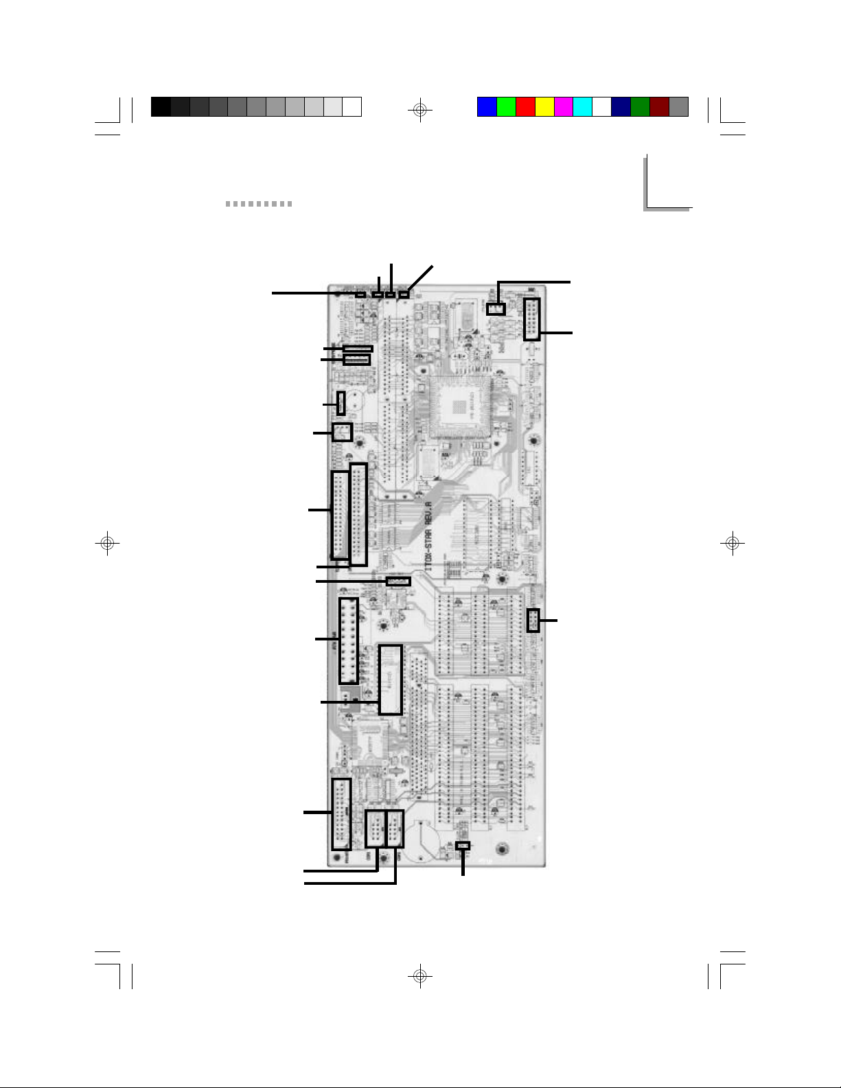
The following connectors and jumper pins are provided on the ITOXSTAR motherboard. Connector locations on the Tiger Star motherboard
are shown on the figure in this appendix.
Refer to the appropriate figures in chapter two for the location of the
external connectors
Connector Function
J1 Printer connector
J2 IR connector (not enabled)
J3 ATX Power connector
J4 Floppy disk connector
J5 IDE connector
J6 Chassis Fan connector
J7 Internal Speaker (Unused)
J8A Keyboard connector , AT type
J8B Connector for PS/2 style mouse
J9 Standby (Unused)
J10 Com1 connector
J11 Power LED
J12 HDD LED
J13 Com2 connector
J14 Chassis open connector (Tamper Switch)
J15 Reset (Unused)
J16 ATX Power Switch
J17 CPU Fan connector
J18 VGA connector
40
Page 43
ITOX-STAR Motherboard Layout and Jumpers
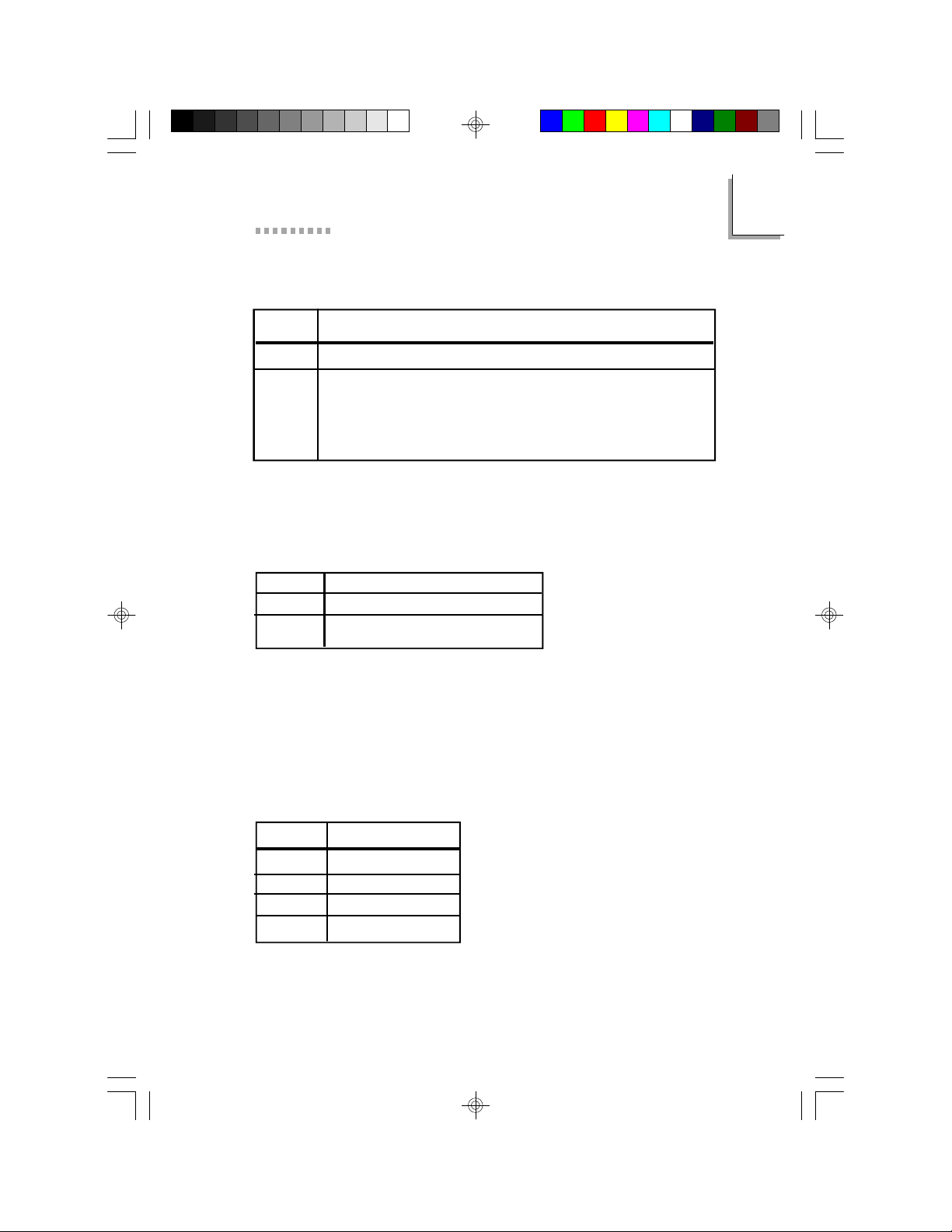
JP2: For CMOS Setting
JP2 FUNCTION
1-2 Normal (As shipped with default postions)
2-3 Clear (Resets all BIOS parameters to default)
It will take about 5 seconds. The power
must be on when the jumper is in place
to clear the BIOS.
Default: 1-2 ON
JP4: For BIOS Size Setting
JP4 EPROM Size
1-2 1M bit
2-3 2M bit
Default: 1-2 ON (Factory Default)
The standard Tiger Star BIOS uses a 1M bit EPROM.
This jumper should not be changed.
A
JP5: For M-system Flash Disk
Address Select
JP5 Address
1-2 C0000
3-4 C8000
5-6 D0000
7-8 D8000
Default: 3-4 On
41
Page 44
A
Appendix A
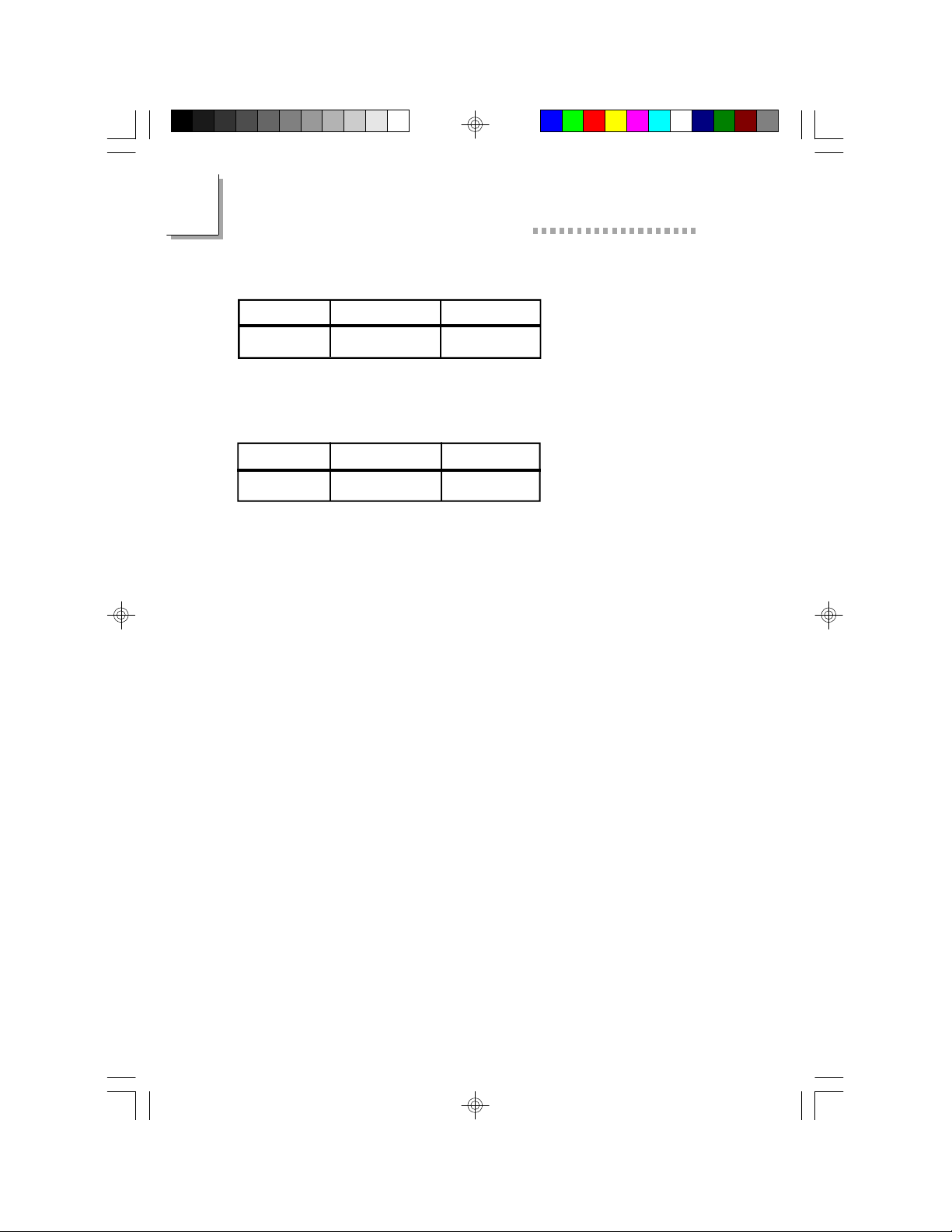
J11: Power LED Connector
Pin 1 2
Function LED Power GND
J12: HDD LED Connector
Pin 1 2
Function LED Power GND
42
Page 45
ITOX-STAR Motherboard Layout and Jumpers
J11
Power LED
J8B -PS2 Mouse
J8A -Keyboard
J7 -Speaker
J6 -Fan
J4 -Floppy*
J5 -IDE*
J14 -Chassis
Switch
J3 -Power*
U7 -Socket for
Flash Disk
J12
HD LED
J15
Reset
A
J16 -ATX Power Switch
J17 -
CPU Fan
J18 -VGA
JP5 -
M-system
Flash Disk
Address
Select
J1 -LPT
J10 -COM1
J13 -COM2
*Located on back of board
JP2 -Clear CMOS
43
Page 46

44
Page 47
APPENDIX
B
Watchdog Timer
Page 48

46
Page 49

Using the Watchdog Timer Function
The following are the parameters for enabling or disabling the Watchdog Timer function when using ASSEMBLY or GWBASIC applications.
When enabled, the application accesses read port 443 (HEX). When
disabled, it accesses read port 43 (HEX).
To set the timer see peripheral setup, Watchdog Timer on page 35. The
default setting is 4 sec. To initiate the program you must type the following.
IN ASSEMBLY
To enable Watchdog Timer and reload the timer, type:
MOV DX, 0443H
IN AL, DX
To disable, type:
MOV DX, 043H
IN AL, DX
IN GWBASIC
To enable Watchdog Timer and reload the timer, type:
A = INP (&H443)
To disable, type:
A = INP (&H43)
Please note that your custom software must regularly reload the timer
(by reading that port) before the Watchdog Timer times out. Otherwise,
the system will think the machine has already hung-up and will next
reboot.
Remember to disable it before the software ends/exits.
Page 50

48
Page 51
Appendix
C
Video Subsystem
Page 52
C
Appendix C
50
50
Page 53
Video Subsystem
Graphics Driver Installation
The ITOX-STAR board comes with a VGA driver diskette ( UMA.txt). To
install the VGA drivers, please refer to the “Readme” file contained in the
provided diskette.
All steps or procedures to install software drivers are subject to change
without notice since the software may be updated. Please refer to the
readme files for the latest information.
VGA Frame Buffer Size
The STPC processor uses a portion of the main memory as a video buffer.
The size of the video buffer can be set within the BIOS as described in
Chapter 3. The following buffer sizes are recommended for the resolutions and number of colors as shown in the chart below.
Recommended Video Frame Buffer Size
Resolution 256 colors 65,000 colors 16.7 million
(8-bit) (16-bit) colors (24-bit
true color)
640 x 480 512K 1 MB 1 MB
800 x 600 512K 1 MB 2 MB
1024 x 768 1 MB 2 MB 4 MB
1152 x 1024 2 MB 2 MB 4 MB
1280 x 1024 2 MB 4 MB 4 MB
1600 x 1200 2 MB 4 MB 6 MB
C
51
Page 54

52
Page 55

Appendix
D
Frequently Asked
Questions & Answers
Troubleshooting
Page 56

D
Appendix D
Frequently Asked Tiger Star Questions
Q: The first time I turn on the machine the message
“ CMOS Checksum Bad” appears.
A: This message is normal and will occur only during “first -time
turn-on” and when F2 is pressed during BIOS default setup.
Either
Press F1 to RUN SETUP
This will take you to the CMOS setup screen.
Make the desired changes (ie. time, floppy, etc.) then save the
value. This error message will not appear again.
Or
Press F2 to load default values and continue.
Q: My VGA quality is very bad. What could be wrong?
A: First check that your DRAM is placed in two DRAM
SIMMS slots. The embedded VGA function uses 64 bit wide data,
while the SIMMS use only 32 bit wide data.
Q: Windows 95 displays this message at startup,
“Your display adapter is not configured properly”.
A: Press OK and let Windows 95 proceed with hardware automatic
detection. Windows 95 will install the standard VGA driver.
Then install the VGA driver supplied with the system.
Q: Windows 95 crashes at startup.
A: Enter BIOS to verify VGA frame buffer size (see advanced
chipset setup in chapter 3).
54
Page 57

Troubleshooting
Q: The top or bottom part of the screen is not displayed.
A: Enter BIOS to verify TV output is disabled (chipset setup).
If you want to use TV output, add black borders in the screen part
of UMA (Unified memory architecture) configuration sheet page
(Control Panel - Display icon).
Troubleshooting Checklist
This chapter of the manual is designed to help you with problems
that you may encounter with the Tiger Star. To efficiently
troubleshoot your system, treat each problem individually. This is
to ensure an accurate diagnosis of the problem in case a problem
has multiple causes.
Some of the most common things to check when you encounter
problems while using your system are listed below.
1. The power switch of each peripheral device is turned on.
2. All cables and power cords are tightly connected.
3. The electrical outlet to which your peripheral devices are
connected is working. Test the outlet by plugging in a
lamp or other electrical device.
D
4. The monitor is turned on.
5. The display’s brightness and contrast controls are adjusted properly.
6. All add-in boards in the expansion slots are seated
securely.
7. Any add-in board you have installed is designed for your
system and is set up correctly. This includes setting up
the BIOS to support the device.
55
Page 58

D
Appendix D
Monitor/Display
If the display screen remains dark after the system is
turned on:
1. Make sure that the monitor’s power switch is on.
2. Check that one end of the monitor’s power cord is prop
erly attached to the monitor and the other end is plugged
into a working AC outlet. If necessary, try another outlet.
3. Check that the video input cable is properly attached to
the monitor and the system’s display adapter.
4. Adjust the brightness of the display by turning the monitor’s brightness control knob.
The picture seems to be constantly moving.
1. The monitor has lost its vertical sync. Adjust the monitor’s vertical sync.
2. Move away any objects, such as another monitor or fan,
that may be creating a magnetic field around the display.
3. Make sure your video card’s output frequencies are sup
ported by this monitor.
The screen seems to be constantly wavering.
1. If the monitor is close to another monitor, the adjacent
monitor may need to be turned off. Fluorescent lights adjacent to the monitor may also cause screen wavering.
Floppy Drive
The computer cannot access the floppy drive.
1. The floppy diskette may not be formatted. Format the
diskette and try again.
2. The diskette may be write-protected. Use a diskette that
is not write-protected.
56
Page 59

Troubleshooting
3. You may be writing to the wrong drive. Check the path
statement to make sure you are writing to the targeted
drive.
4. There is not enough space left on the diskette. Use another diskette with adequate storage space.
Hard Drive
Hard disk failure.
1. Make sure the correct drive type for the hard disk drive
has been entered in the BIOS.
2. If the system is configured with two hard drives, make
sure the bootable (first) hard drive is configured as Master and the second hard drive is configured as Slave.
The master hard drive must have an active/bootable partition.
Excessively long formatting period.
1. If your hard drive takes an excessively long period of
time to format, it is likely a cable connection problem.
However, if your hard drive has a large capacity, it will
take a longer time to format.
D
Parallel Port
The parallel printer doesn’t respond when you try to print.
1. Make sure that your printer is turned on and that the
printer is on-line.
2. Make sure your software is configured for the right type
of printer attached.
3. Verify that the onboard LPT port’s I/O address and IRQ
settings are configured correctly.
4. Verify that the attached device works by attaching it to a
parallel port that is working and configured correctly. If it
57
Page 60

D
Appendix D
works, the printer can be assumed to be in good condition. If the printer remains inoperative, replace the printer
cable and try again.
Serial Port
The serial device (modem, printer) doesn’t output anything
or is outputting garbled characters.
1. Make sure that the serial device’s power is turned on
and that the device is on-line.
2. Verify that the device is plugged into the correct serial
port on the rear of the computer.
3. Verify that the attached serial device works by attaching
it to a serial port that is working and configured correctly. If the serial device does not work, either the cable
or the serial device has a problem. If the serial device
works, the problem may be due to the onboard I/O or
the address setting.
4. Make sure the COM settings and I/O address are
configured correctly.
Keyboard
Nothing happens when a key on the keyboard is pressed.
1. Make sure the keyboard is properly connected.
2. Make sure there are no objects resting on the keyboard
and that no keys are pressed during the booting process.
System Board
1. Make sure the add-in card is seated securely in the expansion slot. If the add-in card is loose, power off the
system, re-install the card and power up the system.
2. Check the jumper settings to ensure that the jumpers are
properly set.
58
Page 61

Troubleshooting
3. Verify that all SIMMs are the correct type and that they
seated securely into the SIMM sockets.
4. Make sure the SIMMs are in the correct locations.
5. If the board fails to function, place the board on a flat
surface and seat all socketed components. Gently press
each component into the socket.
6. If you made changes to the BIOS settings, re-enter
setup and load the BIOS defaults.
D
59
Page 62

60
Page 63
Appendix
E
Limited Warranty
Page 64
E
Appendix E
62
62
Page 65

Limited Warranty
Tiger Star Limited Warranty
ITOX, Inc. warrants to the end user of this product that the product will
be in good working condition and free from defects in materials and
workmanship for a period of one year from the date of purchase by the
original end user . Should the product, in the opinion of ITOX, malfunction during the warranty period, ITOX will at its option, repair or replace
the product at no additional charge except as set forth below. Repair and
replacement products will be furnished on an exchange basis, be either
reconditioned or new and will be warranted for either the remainder of the
original end user warranty period or 30 days, which ever is longer. All
replaced parts and products will become the property of ITOX. This
limited warranty does not include service to repair damage to the product
resulting from accident, disaster, misuse, abuse, neglect, or non-ITOX
authorized alterations, modifications, and/or repairs. Products requiring
service under this limited warranty must be returned according to ITOX’s
Return Material Authorization (RMA) policy. ITOX shall make the final
determination as to the existence and cause of any alleged defect.
This limited warranty applies to hardware products only. This warranty is
in lieu of any other warranty, expressed or implied. ITOX makes no other
warranties, expressed or implied, including any warranty of fitness
for a particular purpose or of merchantability. In no event shall ITOX be
liable to the buyer or end-user for direct, indirect, special, or consequential damages such as loss of profits or business opportunities, and in no
event, shall ITOX’s liability exceed the original purchase price. This
warranty gives you specific legal rights; you may also have other rights
which may vary from state to state.
E
Purchasers requesting service under this limited warranty must contact
the ITOX Customer Service Department at (800) 375-8842 or (732) 3902815 to request a Return Material Authorization (RMA) number and
provide the following information:
1. Item(s) to be returned
2. Serial number of each item
3. Invoice date, invoice number and reference number for each item
4. Detailed description of the technical failure
63
Page 66
E
Appendix E
Upon confirmation of the above information, ITOX will issue a RMA
number and appropriate shipping instructions. The item(s) and proof of
purchase date (a copy of the invoice) must be shipped to ITOX freight
prepaid. ITOX will return the repaired/replaced item by prepaid ground
freight.
Check the ITOX website http://www.itox.com for additional warranty
information and updates. This limited warranty is valid only within the
United States. ITOX is not responsible for costs incurred due to shipping,
insurance, customs or duties. International customers should contact
ITOX for warranty information concerning their locality.
64
Page 67
Appendix
F
Year 2000 Compliance
Page 68
F
Appendix F
66
Page 69

Year 2000 Compliance
Year 2000 Compliance
The Tiger Star supports dates beyond December 31, 1999 and is Year 2000
Compliant. Year 2000 compliance has been verified through use of the
YMARK2000 test program developed by NSTL/National Software Testing
Laboratories.
F
67
Page 70

INDEX
Access cover, 12, 15
Battery, 1
BIOS
Type, 7
Setup, 20, 24
Reset, 40
Exiting, 38
Cache, 6
Checklist: package, 9
CMOS (see BIOS)
Connectors
Back panel, 18
Front panel, 17
Motherboard, 43
Date, 21
Disk
Bays, 7
Controller, 7
Drives, 21
Installation, 13
Disk-on-chip, 9
Display, 26
DMA, 33
Electrostatic discharge protection, 12
Expansion cards, 7, 12
Fan, 8
File (driver) loading, 51
General purpose input/output, 7
Indicator lights, 17
Installation
Disk drives, 13
Expansion cards, 12
Hardware, 12
IRQ Assignments, 34
Loading files, 51
LPT1, 18
Memory, 7, 23
Motherboard, 6, 39
Mounting, 14
Operating system, 8
PCI/Plug and play setup, 32
Peripheral setup,
Power management, 29
Power supply, 8
Processor, 6
RAM, 7
Retaining bracket, card, 12, 13
Shadow configuration, 27
Slots, expansion, 7
Specifications, 6
Switches, 17, 18
Time, 21
VGA Frame buffer, 29, 51
Video drivers, 51
Voltage selection, 12
Watchdog timer, 6, 47
68
 Loading...