

Page 1

SR960-N
System Board
User’s Manual
935-SR9601-050G
I03630823
Page 2

Copyright
This publication contains information that is protected by copyright.
No part of it may be reproduced in any form or by any means or
used to make any transformation/adaptation without the prior written permission from the copyright holders.
This publication is provided for informational purposes only. The
manufacturer makes no representations or warranties with respect to
the contents or use of this manual and specifically disclaims any express or implied warranties of merchantability or fitness for any particular purpose. The user will assume the entire risk of the use or the
results of the use of this document. Further, the manufacturer reserves the right to revise this publication and make changes to its
contents at any time, without obligation to notify any person or entity of such revisions or changes.
© 2008. All Rights Reserved.
Trademarks
Product names or trademarks appearing in this manual are for identification purpose only and are the properties of the respective owners.
Page 3

FCC and DOC Statement on Class B
This equipment has been tested and found to comply with the limits
for a Class B digital device, pursuant to Part 15 of the FCC rules.
These limits are designed to provide reasonable protection against
harmful interference when the equipment is operated in a residential
installation. This equipment generates, uses and can radiate radio frequency energy and, if not installed and used in accordance with the
instruction manual, may cause harmful interference to radio communications. However, there is no guarantee that interference will not
occur in a particular installation. If this equipment does cause harmful
interference to radio or television reception, which can be determined
by turning the equipment off and on, the user is encouraged to try
to correct the interference by one or more of the following measures:
• Reorient or relocate the receiving antenna.
• Increase the separation between the equipment and the receiver.
• Connect the equipment into an outlet on a circuit different from
that to which the receiver is connected.
• Consult the dealer or an experienced radio TV technician for
help.
Notice:
1. The changes or modifications not expressly approved by the
party responsible for compliance could void the user's authority
to operate the equipment.
2. Shielded interface cables must be used in order to comply with
the emission limits.
Page 4

Table of Contents
About this Manual................................................................................
Warranty.................................................................................................
Static Electricity Precaution................................................................
Safety Measures.....................................................................................
About the Package...............................................................................
Before Using the System Board.........................................................
Chapter 1 - Introduction....................................................................
Specifications...................................................................................................................................
Features..............................................................................................................................................
Chapter 2 - Hardware Installation....................................................
System Board Layout ..........................................................................................................
System Memory..........................................................................................................................
CPU.......................................................................................................................................................
Jumper Settings............................................................................................................................
Rear Panel I/O Ports.............................................................................................................
I/O Connectors..........................................................................................................................
5
5
6
6
7
7
8
8
10
13
13
14
17
21
29
36
Chapter 3 - BIOS Setup......................................................................
Overview...........................................................................................................................................
Updating the BIOS..................................................................................................................
Chapter 4 - Supported Softwares.....................................................
Drivers for Windows Vista System..........................................................................
Drivers for Windows XP System..............................................................................
Appendix A - Watchdog Timer.............................................................
Appendix B - Troubleshooting..........................................................
Appendix C - Frequently Asked Questions....................................
51
51
82
83
83
100
115
117
121
Page 5

Warranty
1. Warranty does not cover damages or failures that arised from
misuse of the product, inability to use the product, unauthorized
replacement or alteration of components and product specifications.
2. The warranty is void if the product has been subjected to physical abuse, improper installation, modification, accidents or unauthorized repair of the product.
3. Unless otherwise instructed in this user’s manual, the user may
not, under any circumstances, attempt to perform service, adjustments or repairs on the product, whether in or out of warranty.
It must be returned to the purchase point, factory or authorized
service agency for all such work.
4. We will not be liable for any indirect, special, incidental or
consequencial damages to the product that has been modified
or altered.
Page 6

1
Introduction
Static Electricity Precautions
It is quite easy to inadvertently damage your PC, system board,
components or devices even before installing them in your system
unit. Static electrical discharge can damage computer components
without causing any signs of physical damage. You must take extra
care in handling them to ensure against electrostatic build-up.
1. To prevent electrostatic build-up, leave the system board in its
anti-static bag until you are ready to install it.
2. Wear an antistatic wrist strap.
3. Do all preparation work on a static-free surface.
4. Hold the device only by its edges. Be careful not to touch any of
the components, contacts or connections.
5. Avoid touching the pins or contacts on all modules and connectors. Hold modules or connectors by their ends.
Important:
Electrostatic discharge (ESD) can damage your processor,
disk drive and other components. Perform the upgrade instruction procedures described at an ESD workstation
only. If such a station is not available, you can provide
some ESD protection by wearing an antistatic wrist strap
and attaching it to a metal part of the system chassis. If a
wrist strap is unavailable, establish and maintain contact
with the system chassis throughout any procedures requiring ESD protection.
Safety Measures
To avoid damage to the system:
• Use the correct AC input voltage range
To reduce the risk of electric shock:
• Unplug the power cord before removing the system chassis
cover for installation or servicing. After installation or servicing,
cover the system chassis before plugging the power cord.
..
.
..
Battery:
• Danger of explosion if battery incorrectly replaced.
• Replace only with the same or equivalent type recommend
the manufacturer.
• Dispose of used batteries according to local ordinance.
by
6
Page 7

About the Package
The system board package contains the following items. If any of
these items are missing or damaged, please contact your dealer or
sales representative for assistance.
; The system board
; One IDE cable (44-pin to 44-pin)
; One cable with 2 USB ports
; One Serial ATA data cable
; One Serial ATA power cable
; One COM port cable
; One cable with PS/2 keyboard and PS/2 mouse ports
; One power cable
; One front audio card
; One front audio cable
; One CPU cooler
; One “Main Board Utility” CD
; Two AHCI floppy diskettes (32-bit and 64-bit)
; One QR (Quick Reference)
Introduction
1
The system board and accessories in the package may not come
similar to the information listed above. This may differ in accordance
to the sales region or models in which it was sold. For more information about the standard package in your region, please contact
your dealer or sales representative.
Before Using the System Board
Before using the system board, prepare basic system components.
If you are installing the system board in a new system, you will need
at least the following internal components.
• A CPU
• Memory module
• Storage devices such as hard disk drive, CD-ROM, etc.
You will also need external system peripherals you intend to use
which will normally include at least a keyboard, a mouse and a video
display monitor.
7
Page 8

1
Introduction
Chapter 1 - Introduction
Specifications
Processor
Chipset
System Memory
Expansion Slots
Graphics
• Intel® CoreTM2 Duo mobile processor
- 533MHz/800MHz system data bus
• Processor socket: mPGA478P
®
• Intel
• One 200-pin SODIMM socket
• Supports 533MHz and 667MHz DDR2 SDRAM
• Supports maximum of 2GB system memory using 256Mbit,
• 1 PCI-104 slot for 4 PCI devices
• Integrated graphics interface
• Internal graphics features
chipset
-Intel® GME965 Express chipset
-Intel® 82801HBM I/O Controller Hub (ICH8M)
512Mbit, 1Gbit or 2Gbit memory technology for x8 and x16
devices
- Analog CRT
- Integrated 300MHz RAMDAC
- Analog monitor supports up to QXGA (2048x1536@60Hz)
- Supports CRT hot plug
- LVDS interface
- 4:3 aspect ratio panel supports up to UXGA
(1600x1200@75Hz)
- Widescreen panel supports up to WUXGA
(1920x1200@65Hz)
- 25MHz-112MHz single/dual channel @ 18bpp or 24bpp, TFT
panel type support
®
- Mobile Intel
- DVMT 4.0
- Intel® Smart 2D Display Technology
- Estimated 500MHz core render clock at 1.05V core voltage
- High performance MPEG-2 decoding
- WMV9C (VC-1) and H.264 (AVC) support
- Microsoft DirectX 9 and DirectX 10 support
Graphics Media Accelerator X3100
Audio
LAN
IDE
• Realtek ALC262 High Definition audio CODEC
• 2-channel audio output
• 1 stereo DAC supports 16/20/24-bit PCM format with 44.1/48/
96/192KHz sample rate
• 2 stereo ADCs support 16/20-bit PCM format with 44.1/48/96/
192KHz sample rate
• Two Marvell 88E8056 PCI Express Gigabit controllers
• Suppor ts 10Mbps, 100Mbps and 1Gbps data transmission
• IEEE 802.3 (10/100Mbps) and IEEE 802.3ab (1Gbps) compliant
• Supports up to two Ultra ATA 100/66/33 IDE devices
Note: We do not recommend using IDE devices and CF card at
the same time.
8
Page 9

Introduction
1
Serial ATA
Rear I/O
I/O Connectors
• One Serial ATA II interface
• Data transfer rate up to 3Gb/s
• Intel Matrix Storage Technology
• Integrated AHCI controller
• 1 mini-DIN-6 port for PS/2 KB and PS/2 Mouse ports
• 1 DB-9 serial port
• 1 DB-15 VGA port
• 2 RJ45 LAN por ts
• 2 USB 2.0/1.1 ports
• 1 CompactFlash socket
• 2 connectors for 4 additional external USB 2.0/1.1 ports
• 3 connectors for 3 external RS-232 serial ports (two of the
ports are RS-232/RS-422/RS-485 selectable)
• 1 LCD brightness control connector
• 1 LVDS LCD panel connector
• 1 LCD/inverter power connector
• 1 DIO connector and 1 DIO power connector
• 1 front audio connector for line-out and mic-in jacks
• 1 connector for IrDA interface
• 1 Serial ATA connector
• 1 44-pin IDE connector and 1 floppy connector
• 1 10-pin ATX power connector (one 10-to-20 pin ATX power
cable provided)
• 1 front panel connector
• 2 fan connectors
BIOS
Energy Efficient
Design
Damage Free
Intelligence
Temperature
• AMI BIOS
• 4Mbit SPI flash memory
• Supports ACPI specification and OS Directed Power Management
• Suppor ts ACPI STR (Suspend to RAM) function
• Wake-On-Events include:
- Wake-On-PS/2 Keyboard/Mouse
- Wake-On-LAN and Wake-On-Ring
- RTC timer to power-on the system
• System power management supported
• CPU stopped clock control
• Microsoft
• Soft Power supported - ACPI v2.0 specification
• AC power failure recovery
• Monitors CPU/system temperature and overheat alarm
• Monitors CPU(V)/1.5V/3.3V/5V/12V/VBAT(V)/1.8V voltages
and failure alarm
• Monitors CPU/system fan speed and failure alarm
• Read back capability that displays temperature, voltage and fan
speed
• Watchdog timer function
o
C to 60oC
•0
®
/Intel® APM 1.2 compliant
Humidity
PCB
• 10% to 90%
• 10 layers, EPIC form factor, 11.5cm (4.528") x 16.5cm (6.496")
9
Page 10

1
Introduction
Features
watchdog timer
the set time interval. If the system hangs or fails to function, it will
reset at the set time interval so that your system will continue to
operate.
DDR2
GB per second and beyond. That is twice the speed of the conventional DDR without increasing its power consumption. DDR2
SDRAM modules work at 1.8V supply compared to 2.6V memory
voltage for DDR modules. DDR2 also incorporates new innovations
such as the On-Die Termination (ODT) as well as larger 4-bit prefetch against DDR which fetches 2 bits per clock cycle.
graphics
livering exceptional 3D graphics performance. It supports analog
CRT and LVDS interfaces.
DDR2 is a higher performance DDR technology
whose data transfer rate delivers bandwidth of 4.3
The Intel GME965 northbridge chip comes integrated
with the Intel Graphics Media Accelerator X3100 de-
The Watchdog Timer function allows your
application to regularly “clear” the system at
irda
and peripheral devices. The IrDA (Infrared Data Association) specification supports data transfers of 115K baud at a distance of 1
meter.
The system board is equipped with an IrDA connector for wireless connectivity between your computer
10
Page 11

Introduction
1
SERIAL ATA
3Gbps, it improves hard drive performance faster than the standard
parallel ATA whose data transfer rate is 100MB/s.
gigabit lan
sion.
USB
while USB 2.0 supports 480Mb/second bandwidth providing a
marked improvement in device transfer speeds between your computer and a wide range of simultaneously accessible external Plug
and Play peripherals.
wake-on-ring
wake-up/power-on to respond to calls coming from an external modem or respond to calls from a modem PCI card that uses the PCI
PME (Power Management Event) signal to remotely wake up the
PC.
Serial ATA is a storage interface that is compliant
with SATA 1.0a specification. With speed of up to
The two Marvell 88E8056 PCI Express Gigabit
controllers support up to 1Gbps data transmis-
The system board supports USB 2.0 and USB 1.1
ports. USB 1.1 supports 12Mb/second bandwidth
This feature allows the system that is in the
Suspend mode or Soft Power Off mode to
Important:
The 5V_standby power source of your power supply must support ≥720mA.
wake-on-lan
It is supported via the onboard LAN port or via a PCI LAN card
that uses the PCI PME (Power Management Event) signal. However,
if your system is in the Suspend mode, you can power-on the system
only through an IRQ or DMA interrupt.
Important:
The 5V_standby power source of your power supply must support ≥720mA.
This feature allows the network to remotely
wake up a Soft Power Down (Soft-Off) PC.
11
Page 12
1
Introduction
wake-on-PS/2
tem.
Important:
The 5V_standby power source of your power supply must support ≥720mA.
The RTC installed on the system board allows your
rtc timer
system to automatically power-on on the set date
and time.
The system board is designed to meet the ACPI
ACPI STR
(Advanced Configuration and Power Interface) specification. ACPI has energy saving features that enables PCs to implement Power Management and Plug-and-Play with operating systems
that support OS Direct Power Management. ACPI when enabled in
the Power Management Setup will allow you to use the Suspend to
RAM function.
This function allows you to use the PS/2 keyboard or PS/2 mouse to power-on the sys-
With the Suspend to RAM function enabled, you can power-off the
system at once by pressing the power button or selecting “Standby”
®®
®
when you shut down Windows
sometimes tiresome process of closing files, applications and operating system. This is because the system is capable of storing all programs and data files during the entire operating session into RAM
(Random Access Memory) when it powers-off. The operating session
will resume exactly where you left off the next time you power-on
the system.
Important:
The 5V_standby power source of your power supply must support ≥720mA.
Power failure
recovery
automatically.
When power returns after an AC power failure, you may choose to either power-on the
system manually or let the system power-on
®®
without having to go through the
12
Page 13
Hardware Installation
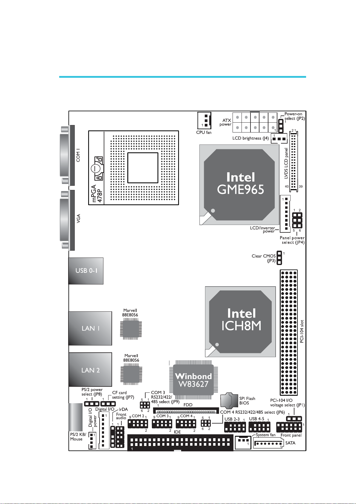
Chapter 2 - Hardware Installation
System Board Layout
2
13
Page 14

2
.
.
.
.
.
.
.
.
Hardware Installation
Warning:
Electrostatic discharge (ESD) can damage your system board, processor, disk drives, add-in boards, and other components. Perform the
upgrade instruction procedures described at an ESD workstation only.
If such a station is not available, you can provide some ESD protection by wearing an antistatic wrist strap and attaching it to a metal
part of the system chassis. If a wrist strap is unavailable, establish
and maintain contact with the system chassis throughout any procedures requiring ESD protection.
System Memory
The system board is equipped with a SODIMM socket located at
the solder side of the board.
SODIMM
BIOS Setting
Configure the system memory in the Chipset menu of the BIOS.
Refer to chapter 3 for more information.
14
Page 15
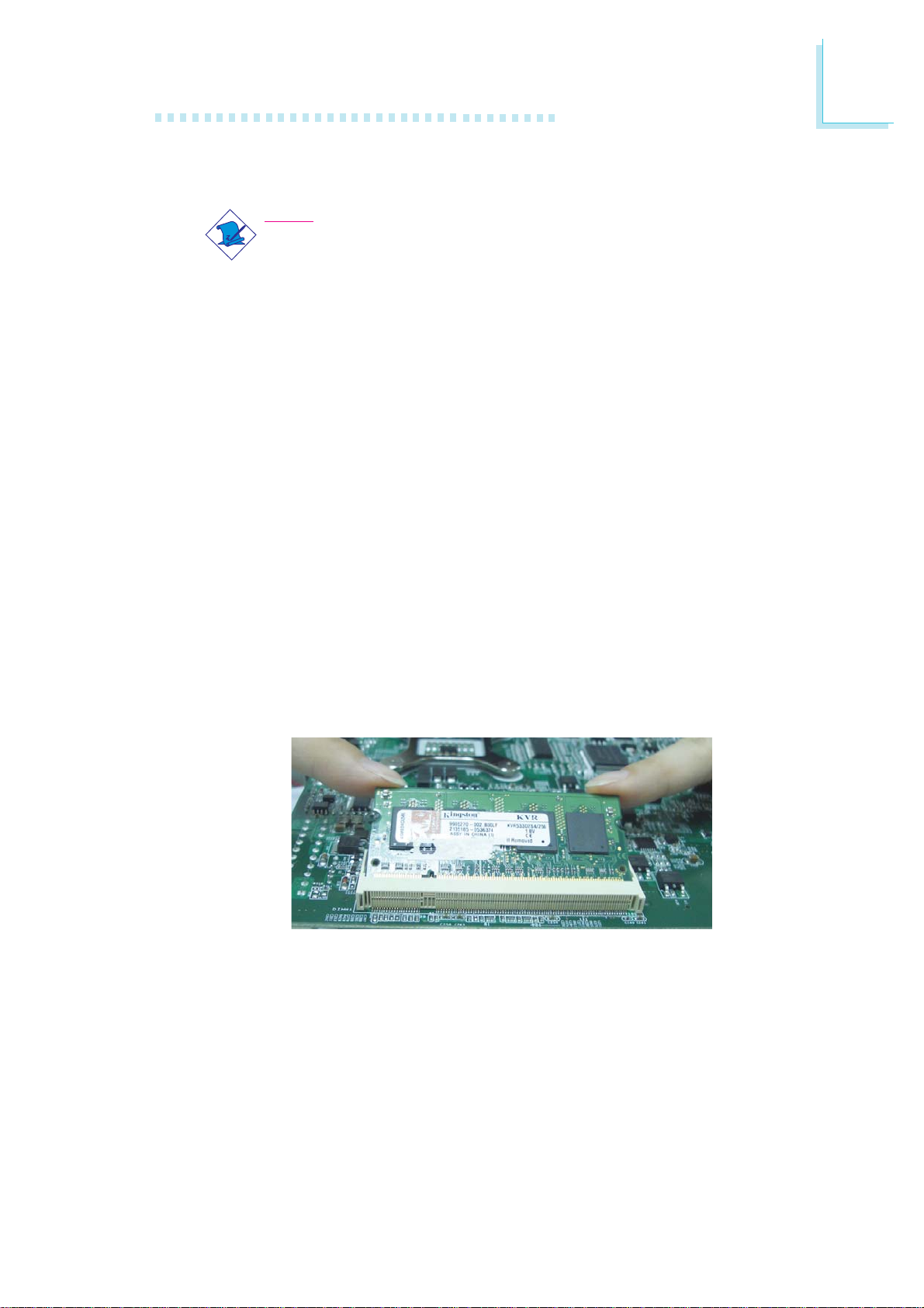
Installing the DIM Module
Note:
The system board used in the following illustrations may not
resemble the actual one. These illustrations are for reference
only.
1. Make sure the PC and all other peripheral devices connected to
it has been powered down.
2. Disconnect all power cords and cables.
3. Locate the SODIMM socket on the system board.
4. Insert the module into the socket at an approximately 30 degrees angle. Note that the socket and module are both keyed,
which means the module can be plugged into the socket in only
one way.
Hardware Installation
2
5. To seat the module into the socket, apply firm even pressure to
each end of the module until it slips down into the socket. The
contact fingers on the edge of the module will almost completely
disappear inside the socket.
15
Page 16
2
Hardware Installation
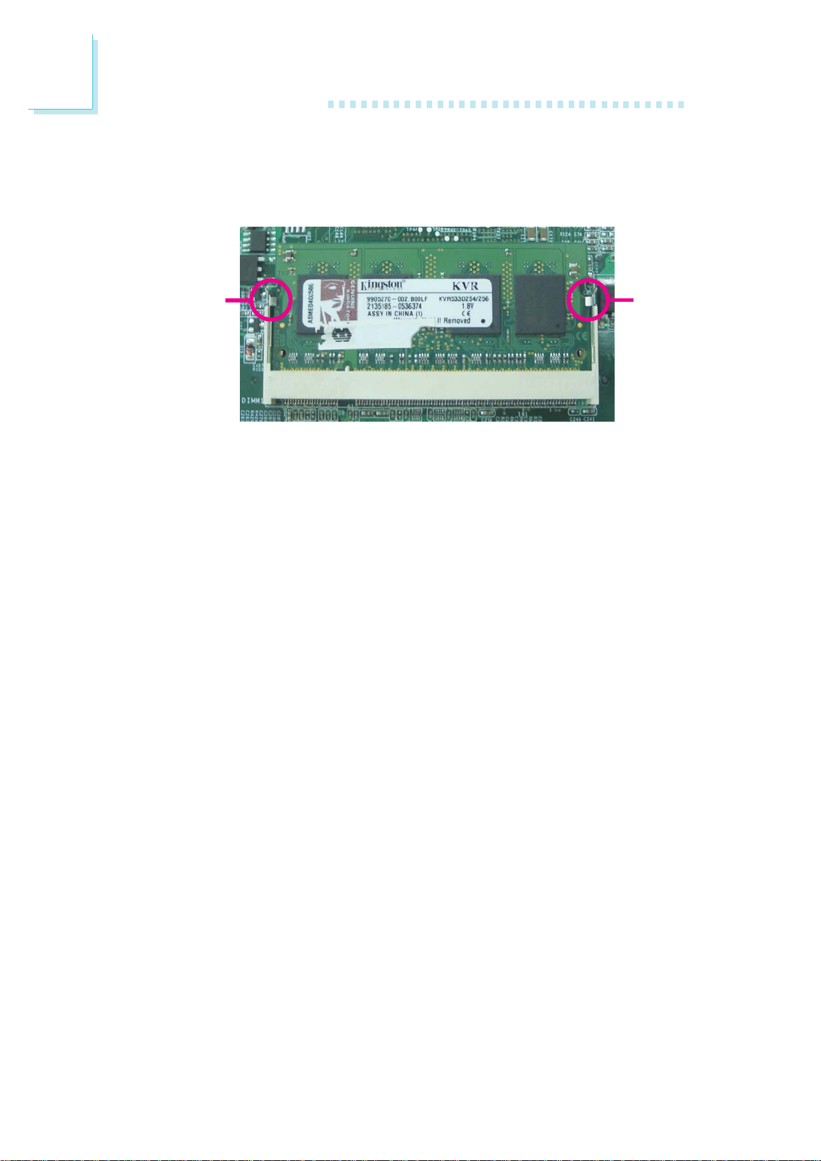
6. Push down the module until the clips at each end of the socket
lock into position. You will hear a distinctive “click”, indicating the
module is correctly locked into position.
ClipClip
16
Page 17
CPU
Overview
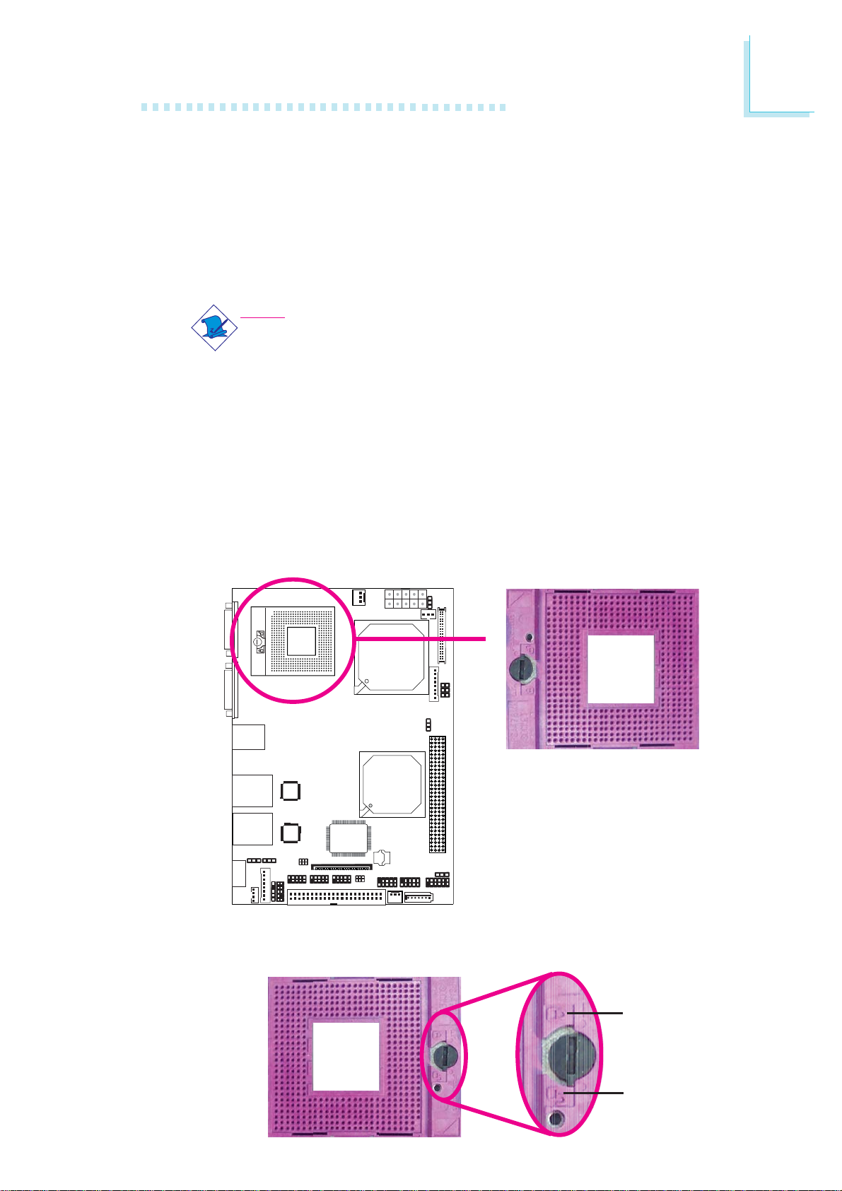
The system board is equipped with a surface mount mPGA478P
CPU socket.
Note:
The system board used in the following illustrations may not resemble the actual one. These illustrations are for reference only.
Installing the CPU
1. Make sure the PC and all other peripheral devices connected to
it has been powered down.
Hardware Installation
2
2. Disconnect all power cords and cables.
3. Locate the mPGA478P socket on the system board.
X
4. Use a screwdriver to turn the screw to its unlock position.
Lock
Unlock
17
Page 18
2
Hardware Installation
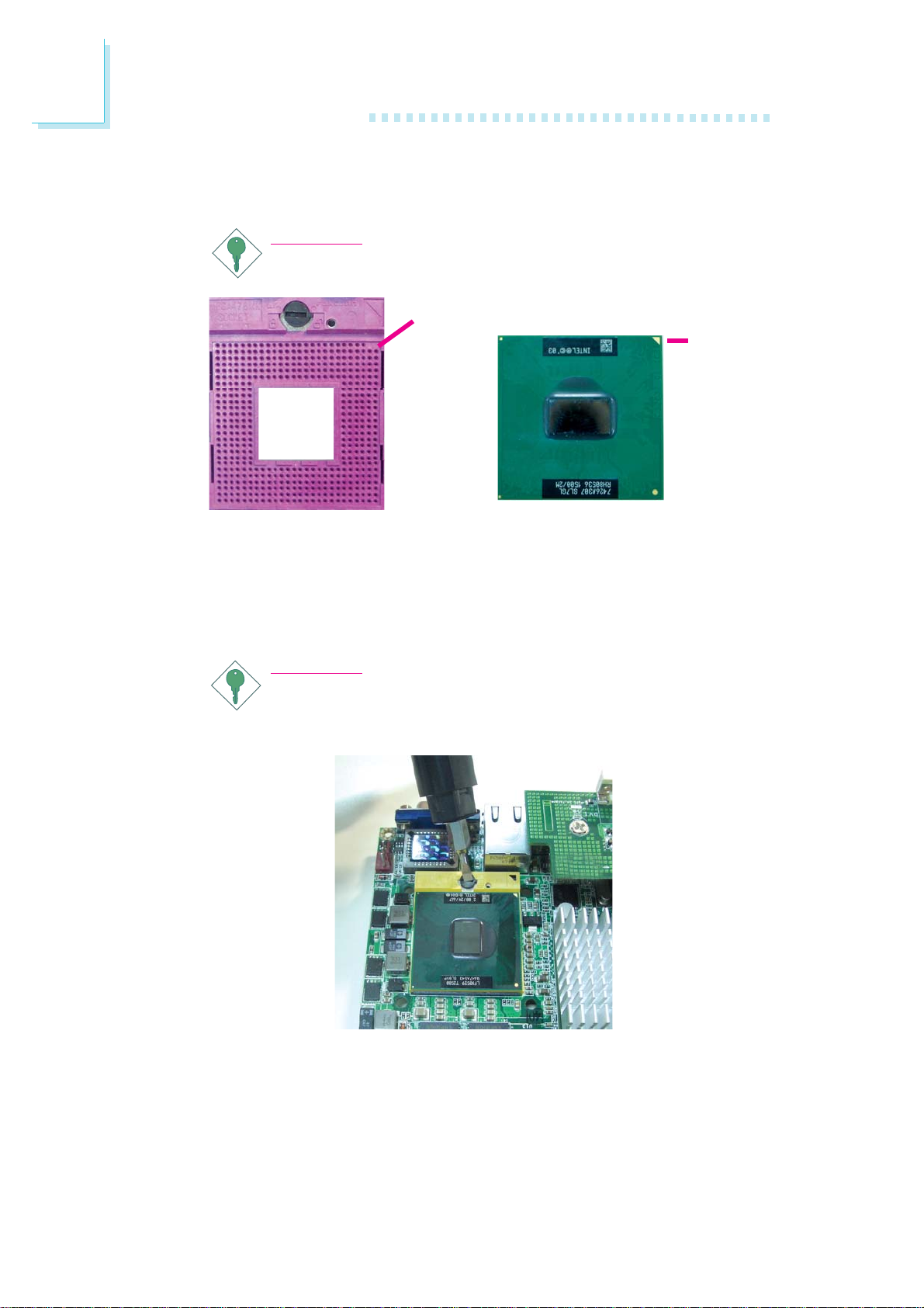
5. Position the CPU above the socket. The gold triangular mark on
the CPU must align with pin 1 of the CPU socket.
Important:
Handle the CPU by its edges and avoid touching the pins.
Pin 1 of the socket
Gold
triangular
mark
6. Insert the CPU into the socket until it is seated in place. The
CPU will fit in only one orientation and can easily be inserted
without exerting any force. Use a screwdriver to turn the screw
to its lock position.
Important:
Do not force the CPU into the socket. Forcing the CPU into
the socket may bend the pins and damage the CPU.
18
Page 19
Installing the Fan and Heat Sink
The CPU must be kept cool by using a CPU fan with heat sink.
Without sufficient air circulation across the CPU and heat sink, the
CPU will overheat damaging both the CPU and system board.
Note:
• Use only certified fan and heat sink.
• Your fan and heat sink package usually contains the fan
and heat sink assembly, and an installation guide. If the installation procedure in the installation guide differs from the
one in this section, please follow the installation guide in the
package.
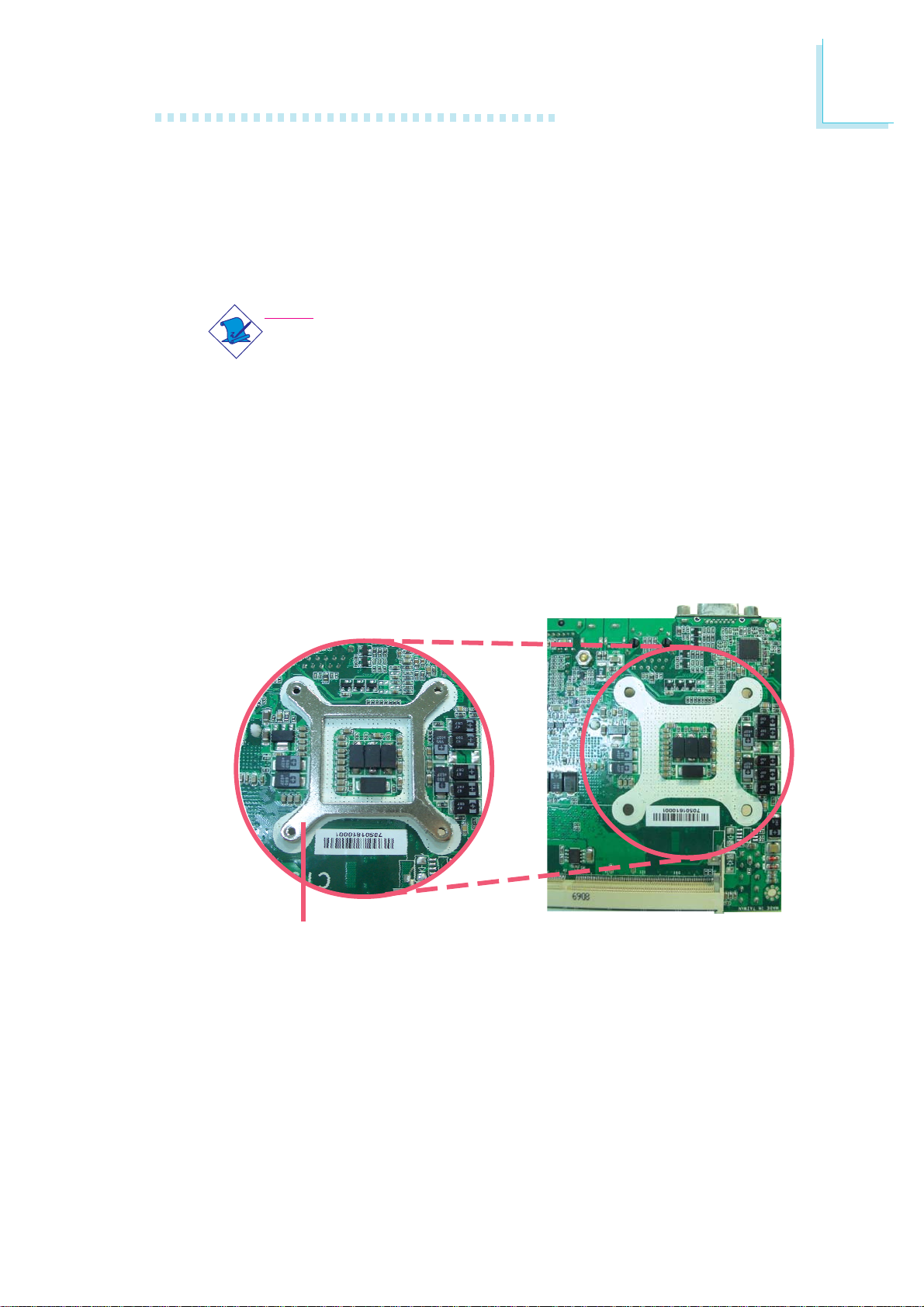
1. On the solder side of the board, match the screw holes of the
retention module base to the mounting holes around the CPU
socket.
Hardware Installation
2
Retention
module base
19
Page 20
2
Hardware Installation
2. Apply a thin layer of thermal paste on top of the CPU. Do not
spread the paste all over the surface. When you later place the
heat sink on top, the compound will disperse evenly.
3. While holding the retention module base in position (step 1),
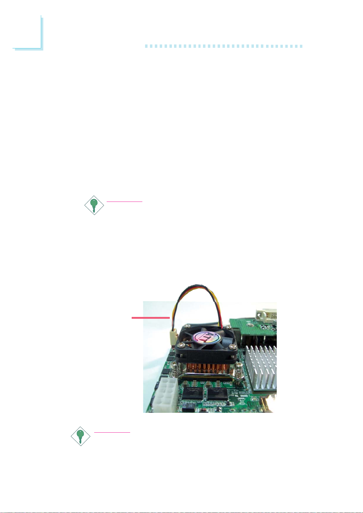
place the fan / heat sink assembly on top of the CPU. The 4
screws around the heat sink must match the screw holes of the
retention module base. We strongly recommend using this type
of fan / heat sink assembly because it provides adequate cooling
to the components of the system board.
Turn each Phillips head screw half way down first to initially stabilize the heat sink onto the board, then finally tighten each screw.
Important:
Do not turn the first screw all the way down followed by
the next and so on. This is to avoid imbalance which might
cause cracks or fractures to the CPU and/or heat sink assembly.
4. Connect the CPU fan’s cable connector to the CPU fan connector on the system board.
CPU fan
cable
Important:
When you install the CPU fan and heat sink assembly, make
sure the assembly is positioned in such a way that the direction of the airflow blows towards the Northbridge. This is to
ensure optimum thermal condition and system performance.
20
Page 21
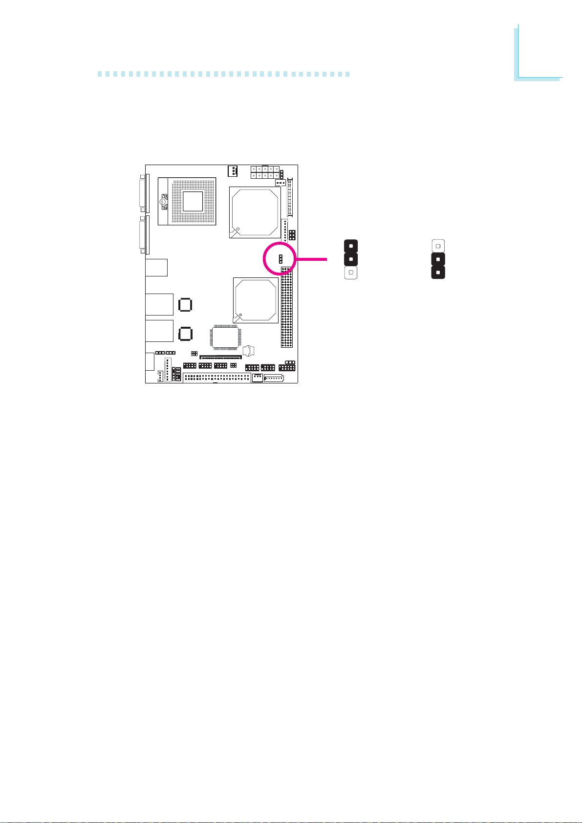
Jumper Settings
Clear CMOS Data
Hardware Installation
2
JP3
X
1-2 On: Normal
1
2
3
(default)
Clear CMOS Data
1
2
3
2-3 On:
If you encounter the following,
a) CMOS data becomes corrupted.
b) You forgot the supervisor or user password.
you can reconfigure the system with the default values stored in the
ROM BIOS.
To load the default values stored in the ROM BIOS, please follow
the steps below.
1. Power-off the system and unplug the power cord.
2. Set JP3 pins 2 and 3 to On. Wait for a few seconds and set JP3
back to its default setting, pins 1 and 2 On.
3. Now plug the power cord and power-on the system.
21
Page 22
2
Hardware Installation
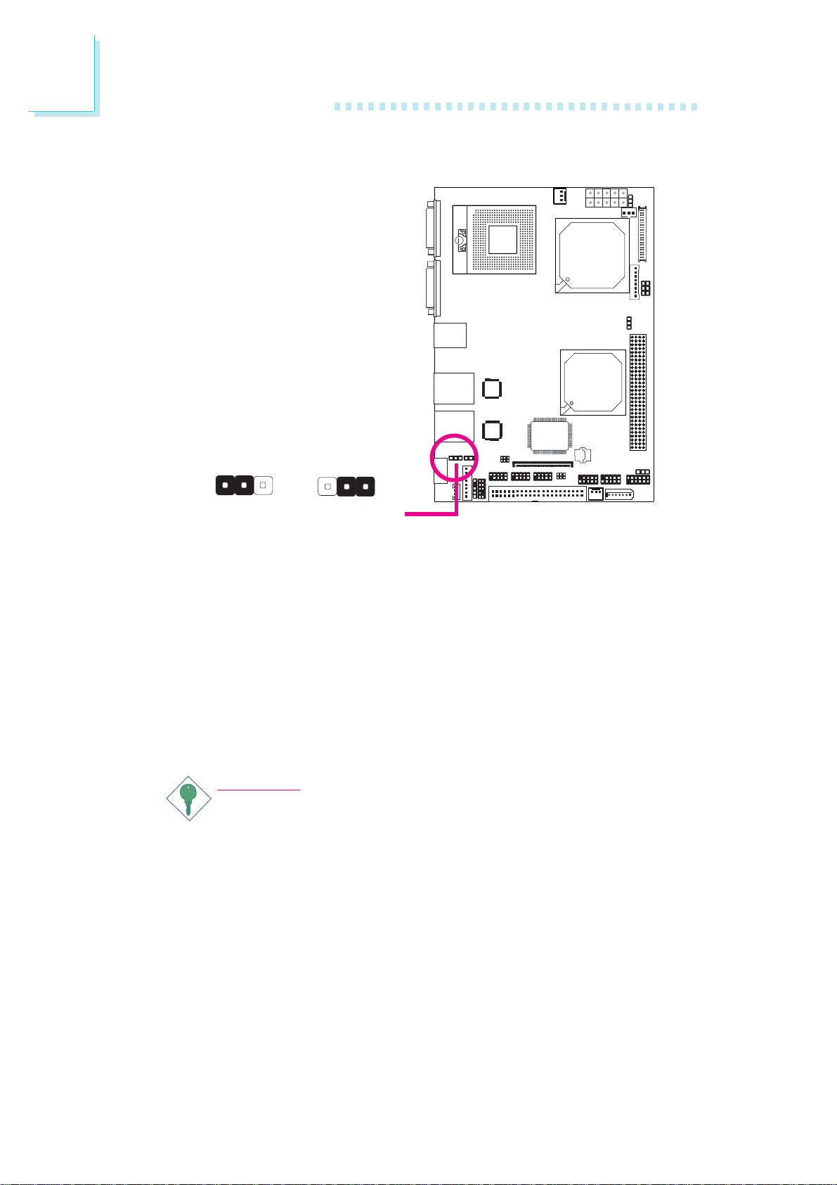
PS/2 Power Select
312
1-2 On: 5V
(default)
JP8 is used to select the power of the PS/2 keyboard/mouse port.
Selecting 5V_standby will allow you to use the PS/2 keyboard or
PS/2 mouse to wake up the system.
BIOS Setting
Configure the PS/2 keyboard/mouse wake up function in the
Advanced menu of the BIOS. Refer to chapter 3 for more information.
Important:
The 5V_standby power source of your power supply must support ≥720mA.
5V_standby
312
2-3 On:
X
JP8
22
Page 23
Hardware Installation
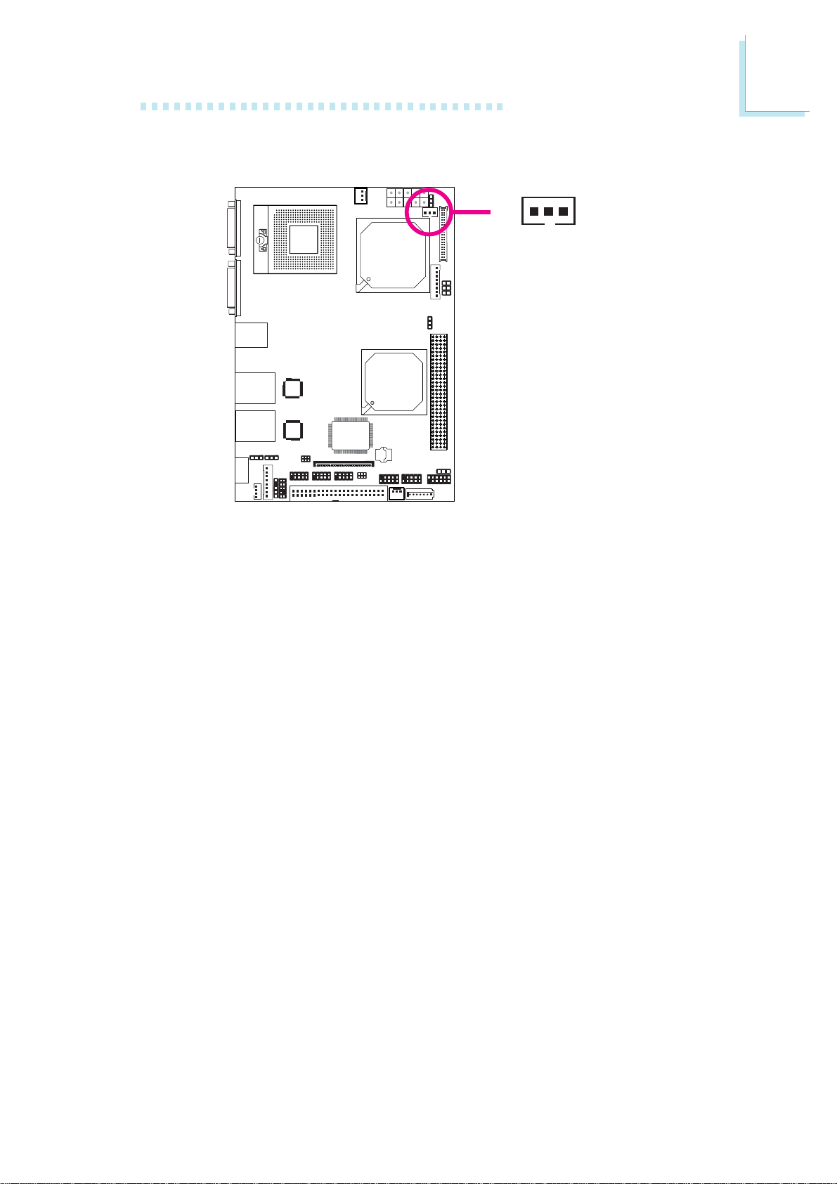
LCD Brightness Control (Voltage Level Adjust)
2
J4
Use J4 to connect to the LCD Brightness Control button of the
LCD Display Panel. It is used to adjust the brightness of the LCD
Display Panel. Increasing or decreasing the voltage to control the
LCD panel’s brightness varies among Inverters. You must refer to the
Inverter’s specification to make the appropriate adjustment to the
brightness of the LCD panel.
1
X
1-2 On:
Increases the voltage level
2-3 On:
Decreases the voltage level
3
23
Page 24
2
Hardware Installation
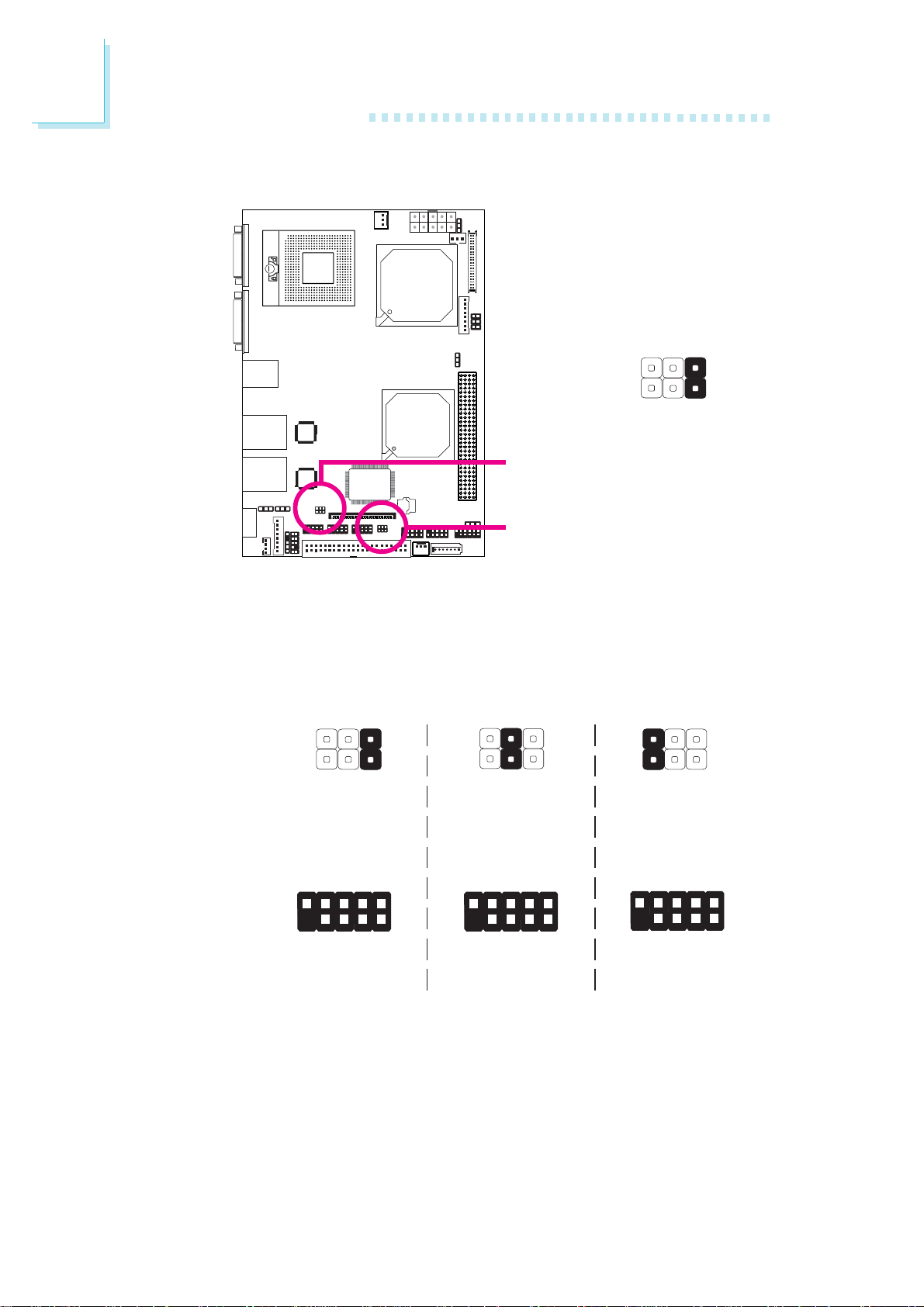
COM 3 and COM 4 RS232/RS422/RS485 Select
COM 3 (JP9)
COM 4 (JP6)
+5V
MRIX-
X_MRIX-
5
6
+12V
1
2
MDCDX-
X_MDCDX-
JP9 and JP6 are used to configure COM 3 and COM 4 respectively
to RS232, RS422 (Half Duplex) or RS485.
The pin function of COM 3 and COM 4 will vary according to the
jumpers’ setting.
JP9/JP6
COM 3
COM 4
9
5
6
1-2 On:
RS232
(default)
RI-
RTS-
CTS-
TD
GND
DSR-
DTR-
1
2
DCD-
1
2
RD
5
6
3-4 On:
RS422
Half Duplex
N. C.
N. C.
9
N. C.
1
2
N. C.
N. C.
RXD+
1
2
RXD-
N. C.
N. C.
5
6
5-6 On:
RS485
N. C.
9
1
2
N. C.
N. C.
N. C.
DATA+
1
2
N. C.
N. C.
N. C.
DATA-
24
Page 25
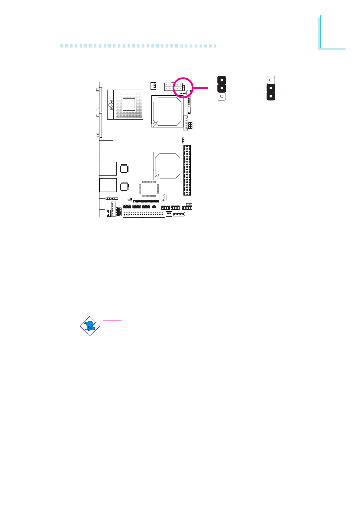
Power-on Select
Hardware Installation
2
JP2
X
1-2 On:
Power-on via
power button
(default)
1
2
3
Power-on via
AC power
1
2
3
2-3 On:
JP2 is used to select the method of powering on the system. If you
want the system to power-on whenever AC power comes in, set
JP2 pins 2 and 3 to On. If you want to use the power button, set
pins 1 and 2 to On.
When using JP2 “Power On” feature to power the system back on
after a power failure occurs, may not power on the system if the
power lost is resumed within 5 seconds (power flicker).
Note:
In order to ensure that power is resumed after a power failure
that may occur within a 5 second period, JP2 should be set to
pins 2-3 and the “Restore on AC Power Loss” in the Advanced
menu of the BIOS is set to “Power On”.
25
Page 26
2
Hardware Installation
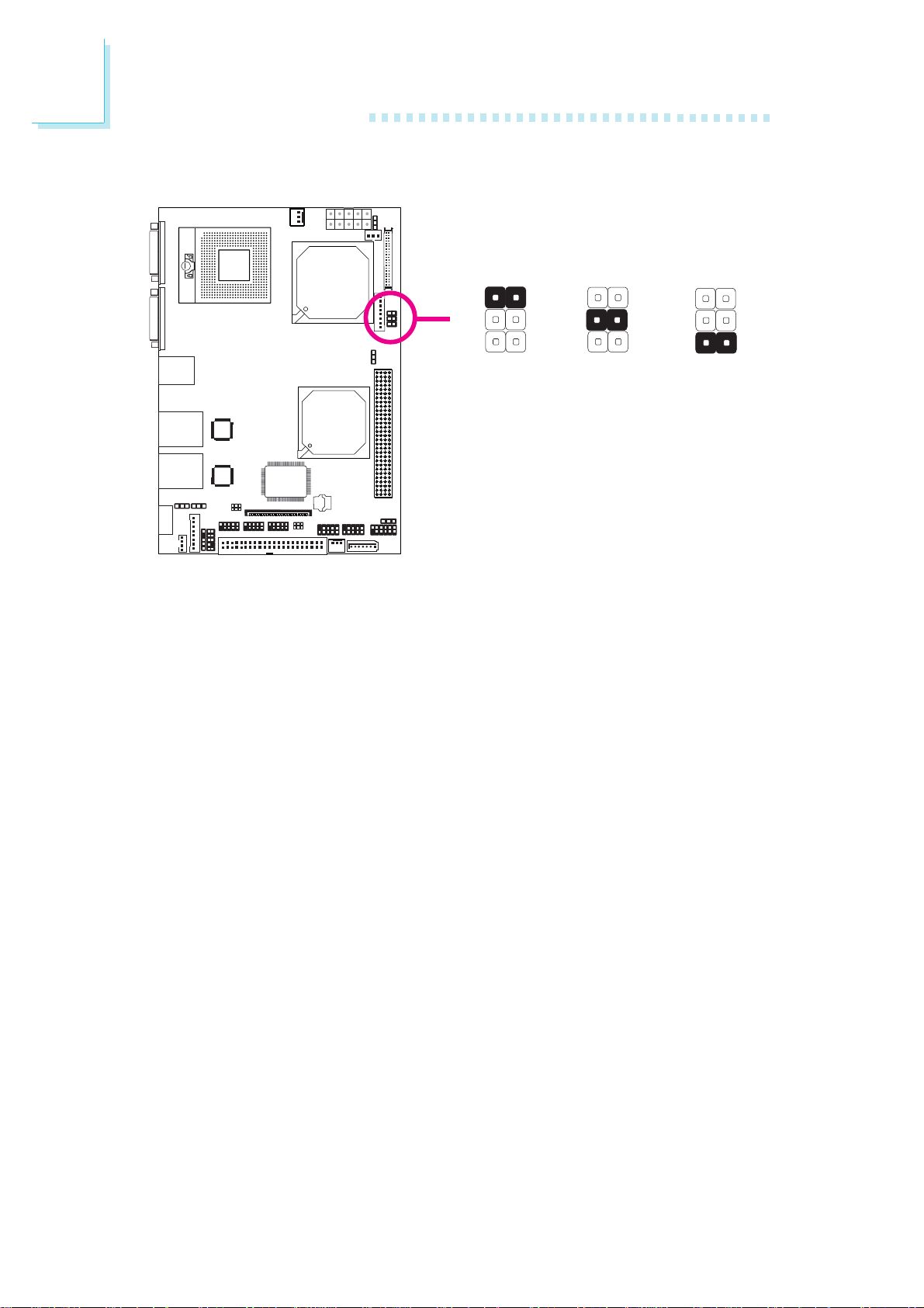
Panel Power Select
JP4
X
1
3
5
1-2 On:
12V
1
2
4
3
6
5
3-4 On:
4
6
5V
1
2
3
5
5-6 On: 3.3V
2
4
6
(default)
JP4 is used to select the power supplied to the LCD panel. Before
powering-on the system, make sure JP4’s setting matches the LCD
panel’s specifications. Selecting the incorrect voltage will seriously damage the LCD panel.
26
Page 27
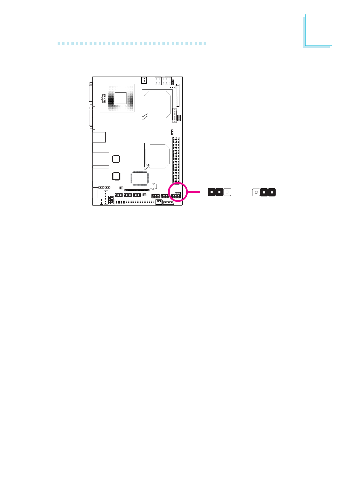
PCI-104 I/O Voltage Select
Hardware Installation
2
JP1
X
1-2 On: 3.3V
JP1 is used to select the voltage supplied to the PCI-104 slot.
312
2-3 On: 5V
(default)
312
27
Page 28
2
Hardware Installation
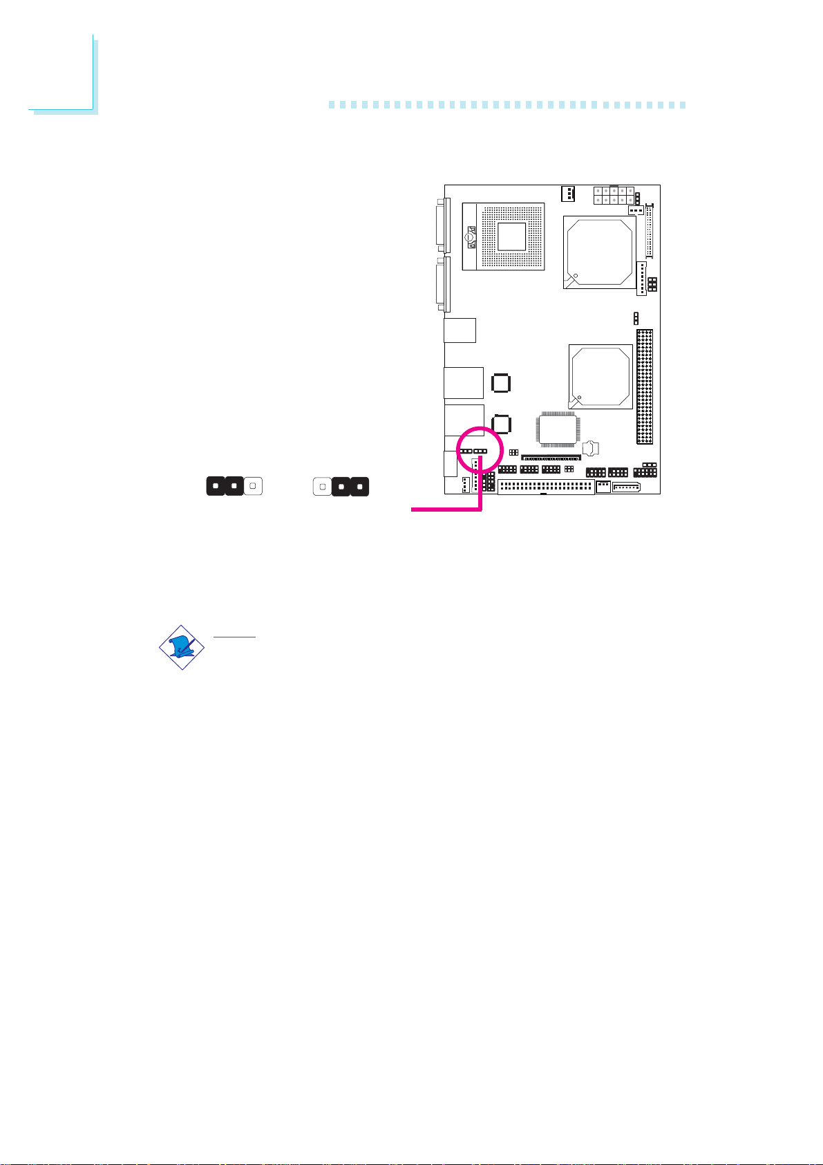
Compact Flash Card Setting
312
1-2 On: Master
(default)
JP7 is used to set the CompactFlashTM socket to Master or Slave
mode.
Note:
We do not recommend using IDE devices and CF card at the
same time.
2-3 On: Slave
312
JP7
X
28
Page 29
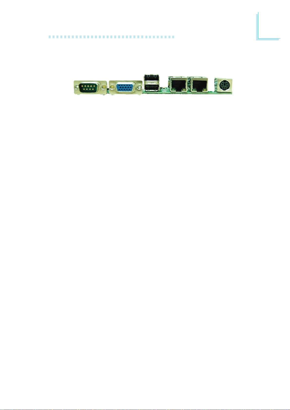
Rear Panel I/O Ports
Hardware Installation
2
USB 0
VGACOM 1
USB 1
The rear panel I/O ports consist of the following:
• DB-9 serial port
• DB-15 VGA port
• USB 2.0/1.1 ports
• RJ45 LAN ports
• PS/2 keyboard/mouse port
LAN 1 LAN 2
PS/2
KB/Mouse
29
Page 30
2
Hardware Installation
Serial Ports
W
COM 1
COM 2
COM 3
COM 4
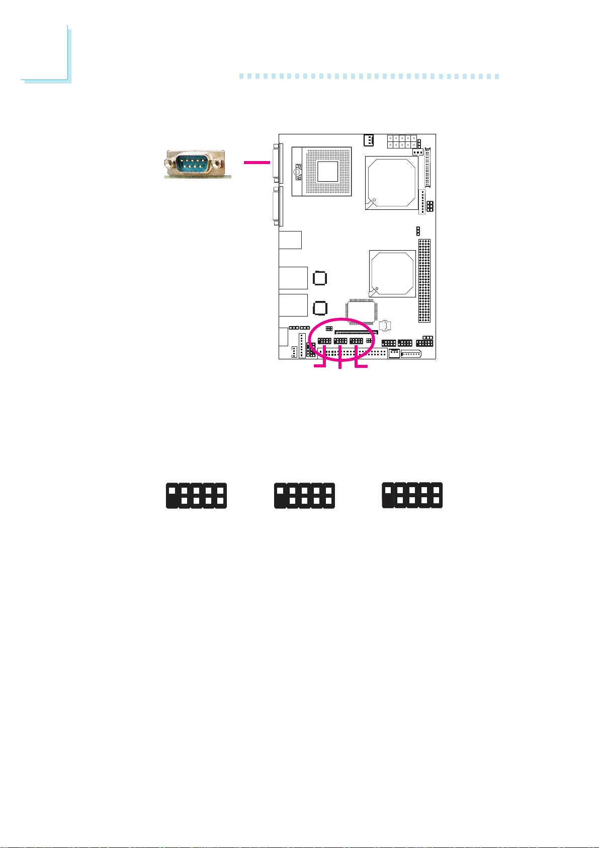
COM 2 is fixed at RS232. COM 3 and COM 4 will vary according
to the settings of JP9 and JP6.
RI-
RTS-
9
CTS-
RS232 RS485RS422
DSR-
DTR-
DCD-
1
2
RD
N. C.
N. C.
N. C.
N. C.
RXD+
9
N. C.
1
2
RXD-
N. C.
N. C.
N. C.
N. C.
N. C.
N. C.
DATA+
9
N. C.
1
2
N. C.
N. C.
DATA-
TD
GND
The serial ports are asynchronous communication ports with
16C550A-compatible UARTs that can be used with modems, serial
printers, remote display terminals, and other serial devices.
Jumper Setting
30
Refer to the “Jumper Settings” section in this chapter for settings
relevant to the serial ports.
BIOS Setting
Configure the serial ports in the Advanced menu of the BIOS. Refer
to chapter 3 for more information.
Page 31
VGA Port
Hardware Installation
2
W
VGA
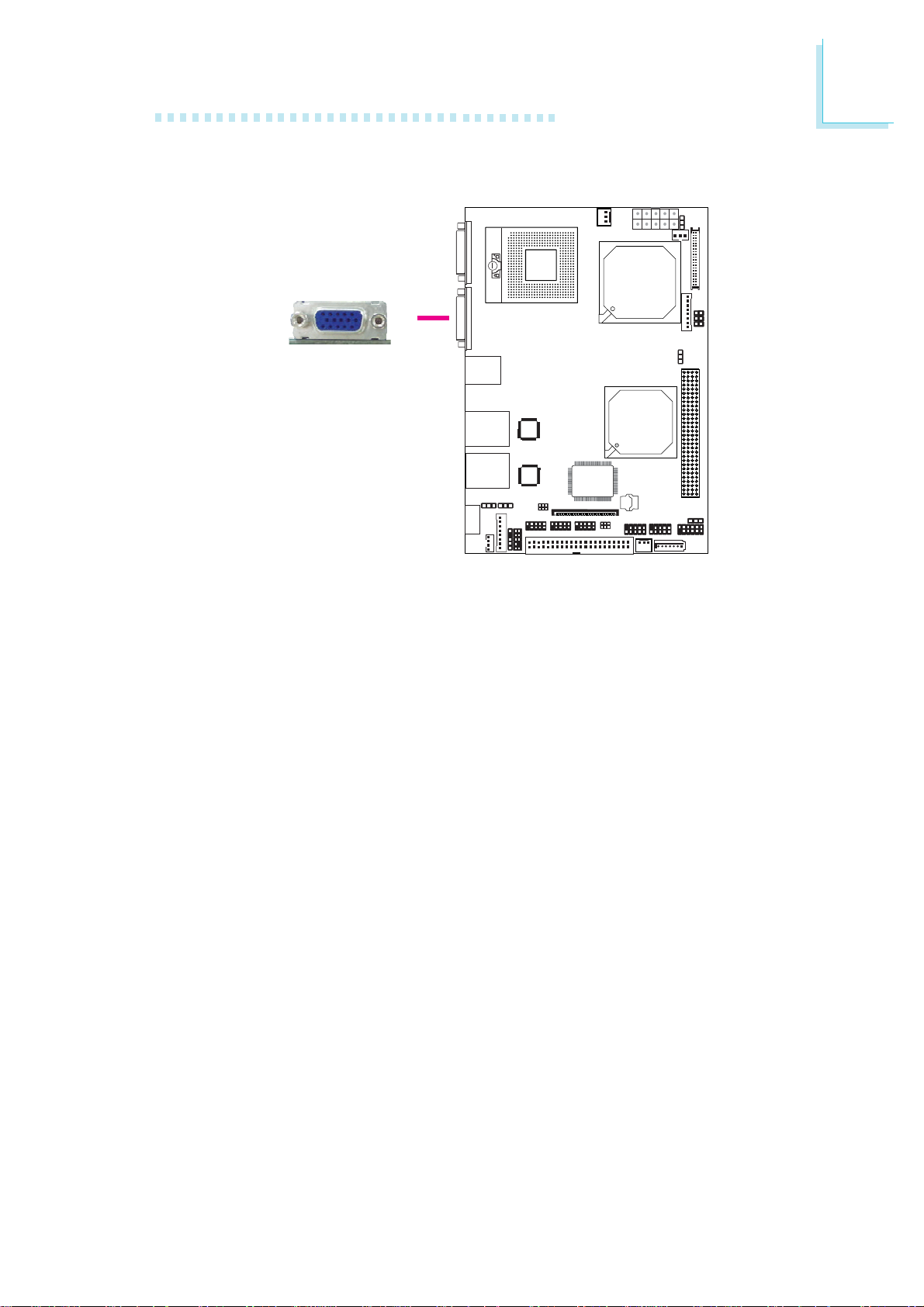
The VGA port is used for connecting a VGA monitor. Connect the
monitor’s 15-pin D-shell cable connector to the VGA port. After you
plug the monitor’s cable connector into the VGA port, gently tighten
the cable screws to hold the connector in place.
BIOS Setting
Configure the onboard VGA in the Chipset menu of the BIOS. Refer
to chapter 3 for more information.
Driver Installation
Install the graphics driver. Refer to chapter 4 for more information.
31
Page 32
2
Hardware Installation
Universal Serial Bus Connectors
USB 1
USB 0
KeyN. C.
9
W
Ground
+Data
-Data
1
W
210
USB 2-3
VCC VCC
-Data
+Data
Ground
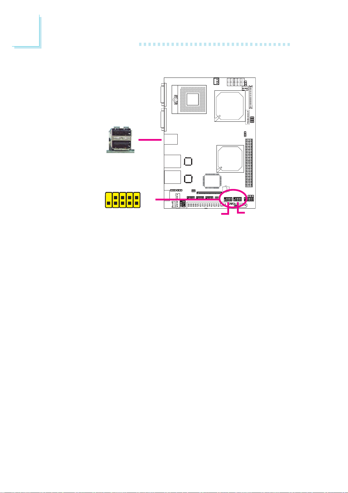
USB allows data exchange between your computer and a wide
range of simultaneously accessible external Plug and Play peripherals.
The system board is equipped with two onboard USB 2.0/1.1 ports.
The USB 2-3 and USB 4-5 connectors allow you to connect 4
additional USB 2.0/1.1 ports. The additional USB ports may be
mounted on a card-edge bracket. Install the card-edge bracket to an
available slot at the rear of the system chassis then insert the connector (that is attached to the USB port cables) to a USB connector.
BIOS Setting
Configure the onboard USB in the Advanced menu of the BIOS.
Refer to chapter 3 for more information.
USB 4-5
32
Driver Installation
You may need to install the proper drivers in your operating system
to use the USB device. Refer to your operating system’s manual or
documentation for more information. Refer to chapter 4 for more
information about installing the USB 2.0 driver.
Page 33
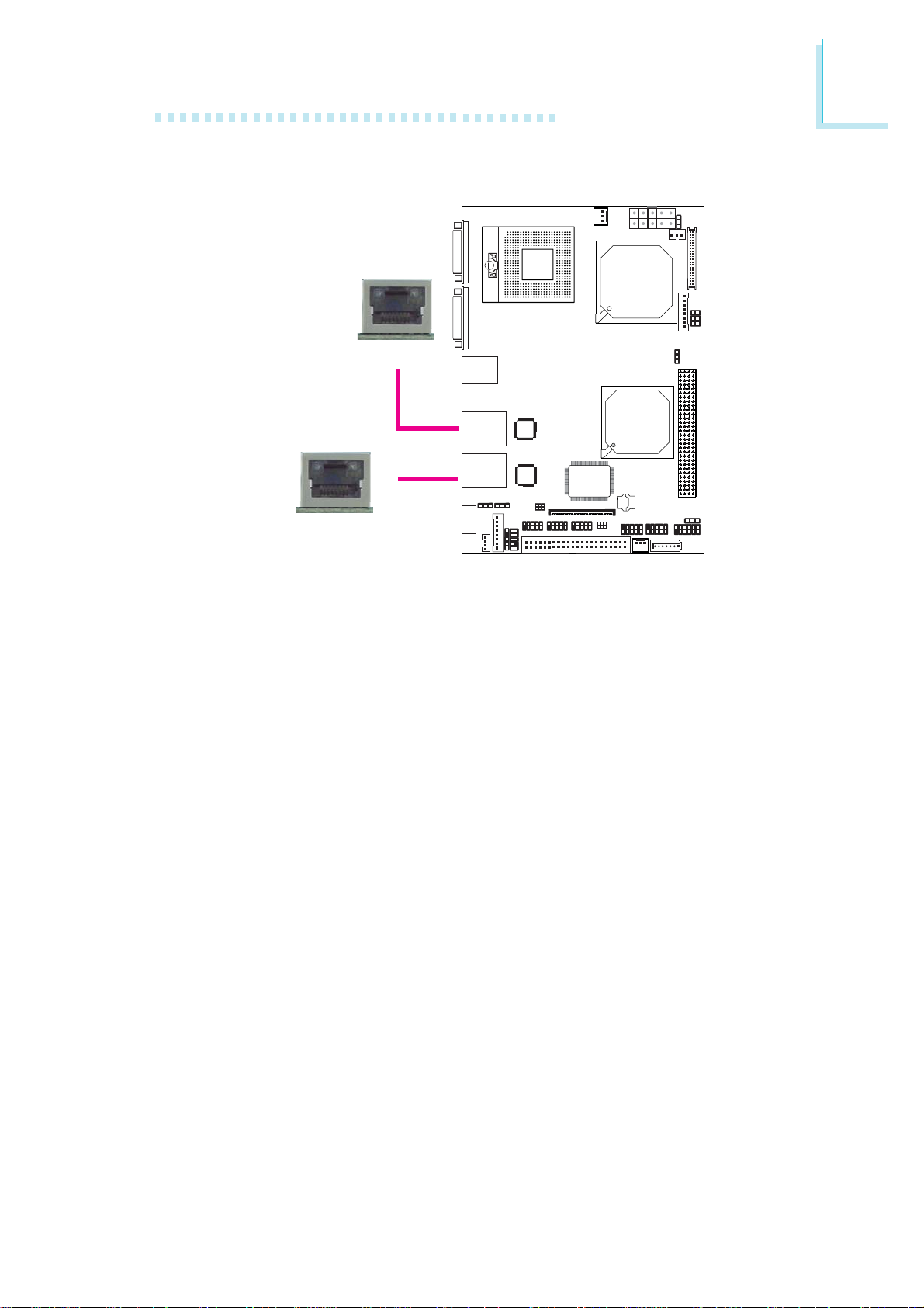
RJ45 Fast-Ethernet Port
LAN 1
W
LAN 2
W
Hardware Installation
2
The LAN ports allow the system board to connect to a local area
network by means of a network hub.
BIOS Setting
Configure the onboard LAN in the Chipset menu of the BIOS. Refer
to chapter 3 for more information.
Driver Installation
Install the LAN drivers. Refer to chapter 4 for more information.
33
Page 34
2
Hardware Installation
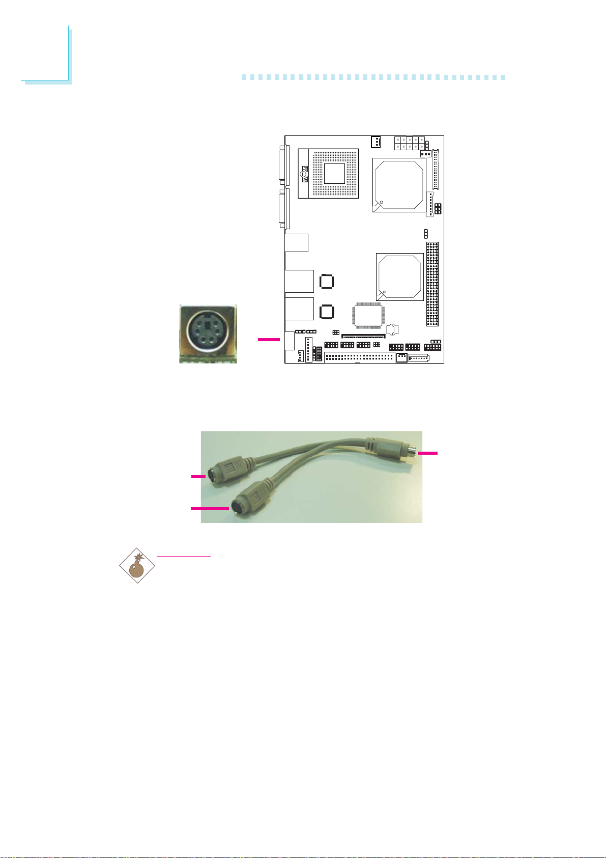
PS/2 Port
W
The PS/2 port allows you to connect a PS/2 keyboard and a PS/2
mouse by means of the provided cable.
Connect to
PS/2 port on
PS/2 keyboard
port
PS/2 mouse
port
.
.
.
.
Warning:
.
.
.
.
the board
Make sure to turn off your computer prior to connecting or
disconnecting a mouse or keyboard. Failure to do so may damage the system board.
Wake-On-PS/2 Keyboard/Mouse
The Wake-On-PS/2 Keyboard/Mouse function allows you to use the
PS/2 keyboard or PS/2 mouse to power-on the system. To use this
function:
34
• Jumper Setting:
JP8 must be set to “2-3 On: 5V_standby”. Refer to “PS/2 Power
Select” in this chapter for more information.
Page 35

Hardware Installation
• BIOS Setting:
Configure the PS/2 keyboard/mouse wake up function in the
Advanced menu of the BIOS. Refer to chapter 3 for more information.
Important:
The 5V_standby power source of your power supply must support ≥720mA.
2
35
Page 36
2
Hardware Installation
I/O Connectors
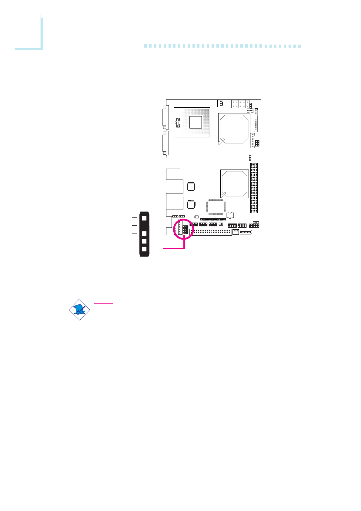
IrDA Connector
VCC
N. C.
IRRX
Ground
IRTX
Connect the cable connector from your IrDA module to the IrDA
connector on the system board.
Note:
The sequence of the pin functions on some IrDA cable may be
reversed from the pin function defined on the system board.
Make sure to connect the cable to the IrDA connector according to their pin functions.
BIOS Setting
Configure the onboard IrDA in the Advanced menu of the BIOS.
Refer to chapter 3 for more information.
1
5
W
36
Driver Installation
You may need to install the proper drivers in your operating system
to use the IrDA function. Refer to your operating system’s manual or
documentation for more information.
Page 37
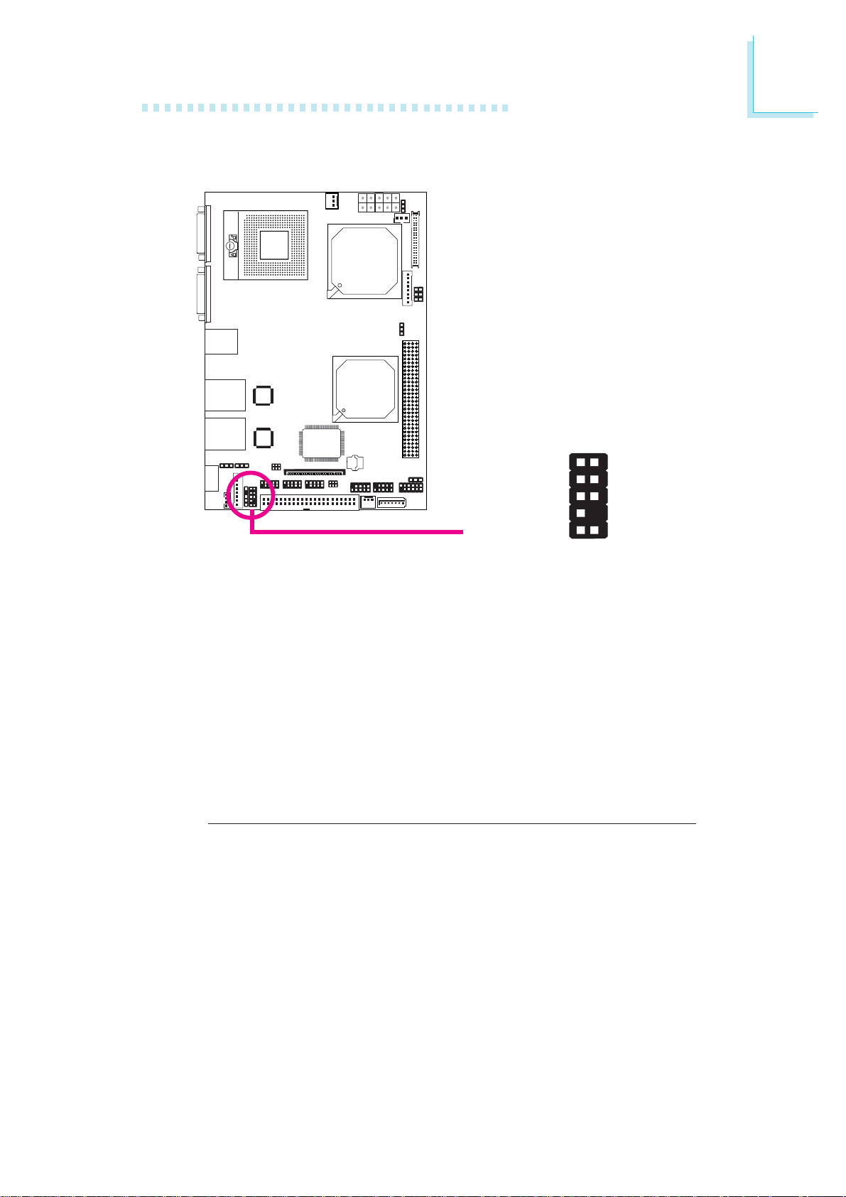
Front Audio Connector
AuD_R_Out
AuD_L_Out
X
Hardware Installation
2
1
Mic GND
AuD_VccN. C.
AuD_R_Return
N. C.
Key
AuD_L_Return
109
2
The front audio connector allows you to connect to the line-out and
mic-in jacks that are at the front panel of your system. Remove the
jumper caps from pins 5-6 and pins 9-10 prior to connecting the
front audio cable connector. Make sure pin 1 of the cable connector
is aligned with pin 1 of the front audio connector. If you are not
using this connector, make sure to replace the jumper caps back to
their original pin locations.
Pins 5-6 and 9-10 short
(default)
Pins 5-6 and 9-10 open
BIOS Setting
Configure the onboard audio in the Chipset menu of the BIOS. Refer to chapter 3 for more information.
The front audio is disabled.
The rear audio is enabled.
The front audio is enabled.
The rear audio is disabled.
Driver Installation
Install the audio driver. Refer to chapter 4 for more information.
37
Page 38
2
Hardware Installation
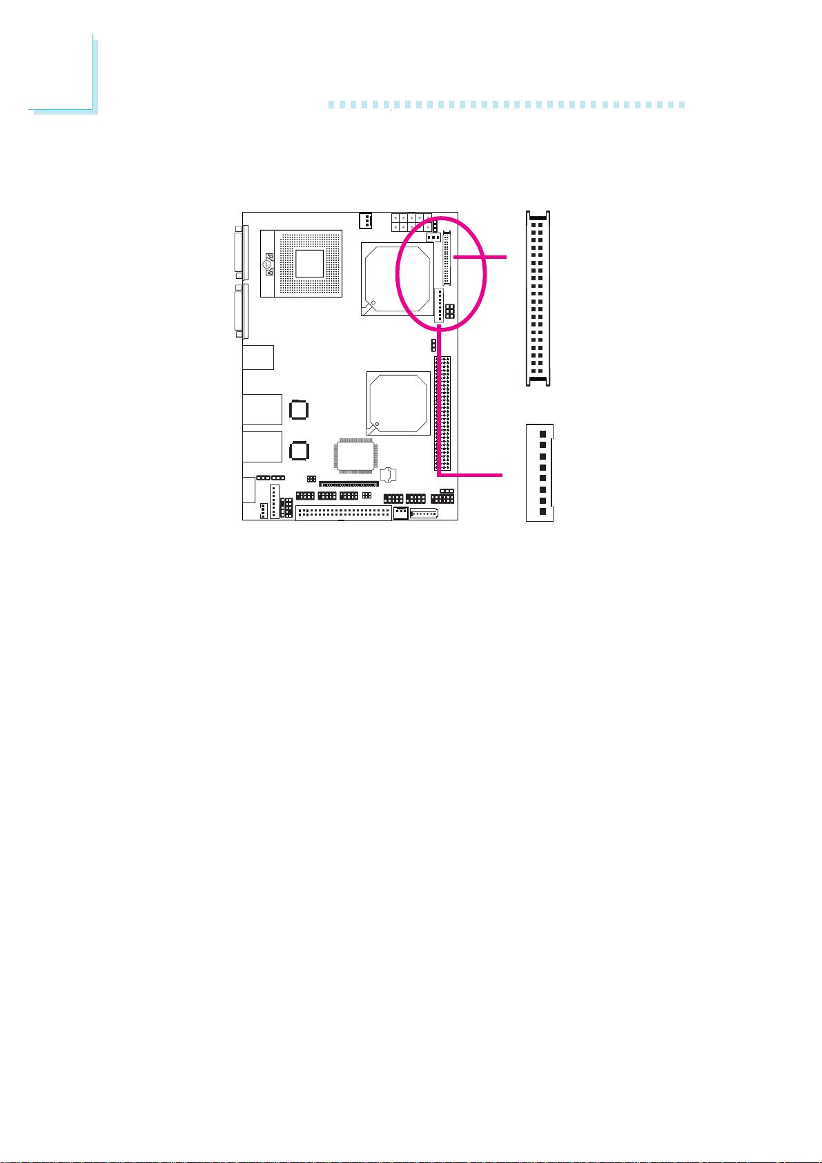
LVDS LCD Panel Connector
LCD/Inverter Power Connector
2
1
X
3940
LVDS LCD Panel
1
X
8
LCD/Inverter
Power
The system board allows you to connect a LCD Display Panel by
means of the LVDS LCD panel connector and the LCD/Inverter
power connector. These connectors transmit video signals and power
from the system board to the LCD Display Panel.
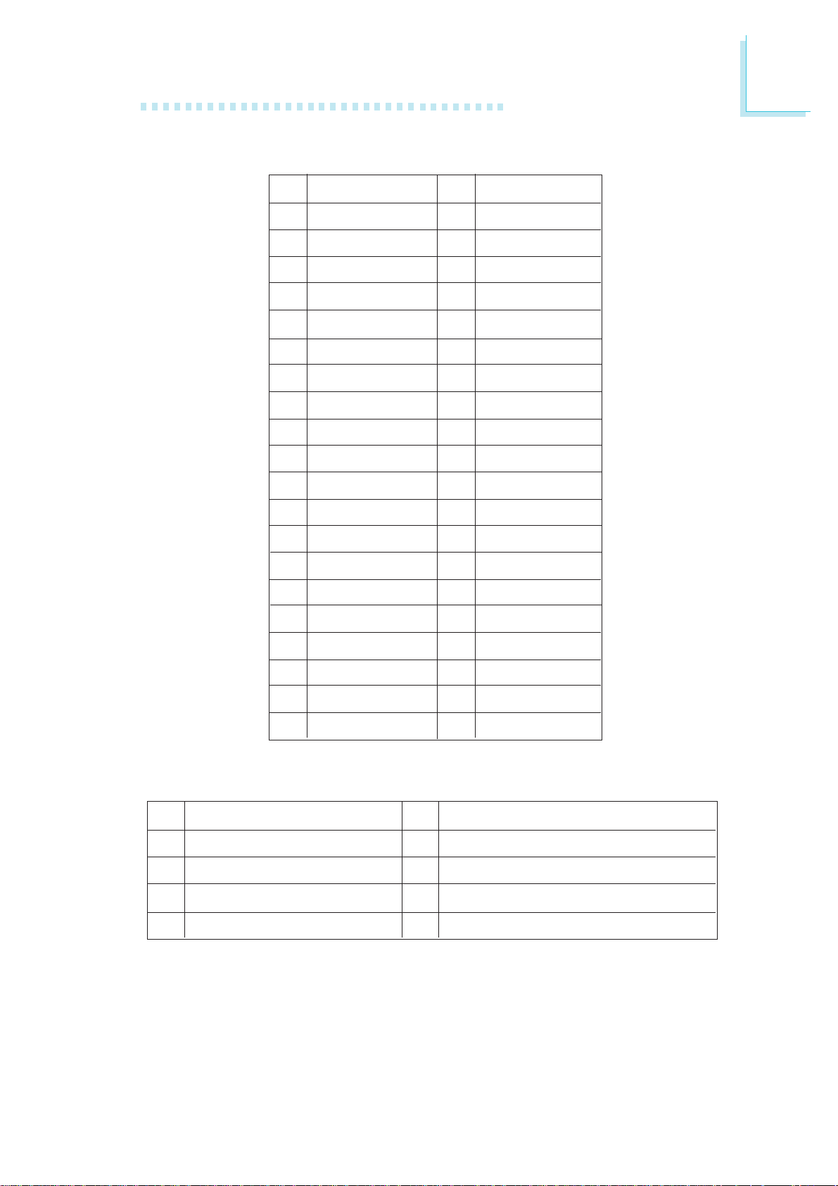
Refer to the next page for the pin functions of these connectors.
Jumper Settings
Refer to the “Jumper Settings” section in this chapter for settings
relevant to the LCD panel.
BIOS Setting
Configure the LCD panel in the Chipset menu of the BIOS. Refer to
chapter 3 for more information.
38
Page 39
Hardware Installation
LVDS LCD Panel Connector
2
Pins
1
3
5
7
9
11
13
15
17
19
21
23
25
27
29
Function
GND
LVDS_Out3+
LVDS_Out3-
GND
LVDS_Out2+
LVDS_Out2-
GND
LVDS_Out1+
LVDS_Out1-
GND
LVDS_Out0+
LVDS_Out0-
GND
LVDS_CLK1+
LVDS_CLK1-
Pins
2
4
6
8
10
12
14
16
18
20
22
24
26
28
30
Function
GND
LVDS_Out7+
LVDS_Out7-
GND
LVDS_Out6+
LVDS_Out6-
GND
LVDS_Out5+
LVDS_Out5-
GND
LVDS_Out4+
LVDS_Out4-
GND
LVDS_CLK2+
LVDS_CLK2-
31
33
35
37
39
LCD/Inverter Power Connector
Pins
8
7
6
Panel Backlight On/Off Control
5
Function
+12V
+12V
N. C.
GND
N. C.
N. C.
Panel Power
Panel Power
32
34
36
38
40
Pins
4
3
Panel Inverter Brightness Voltage Control
2
1
GND
N. C.
N. C.
Panel Power
Panel Power
Function
Panel Power
GND
GND
39
Page 40
2
Hardware Installation
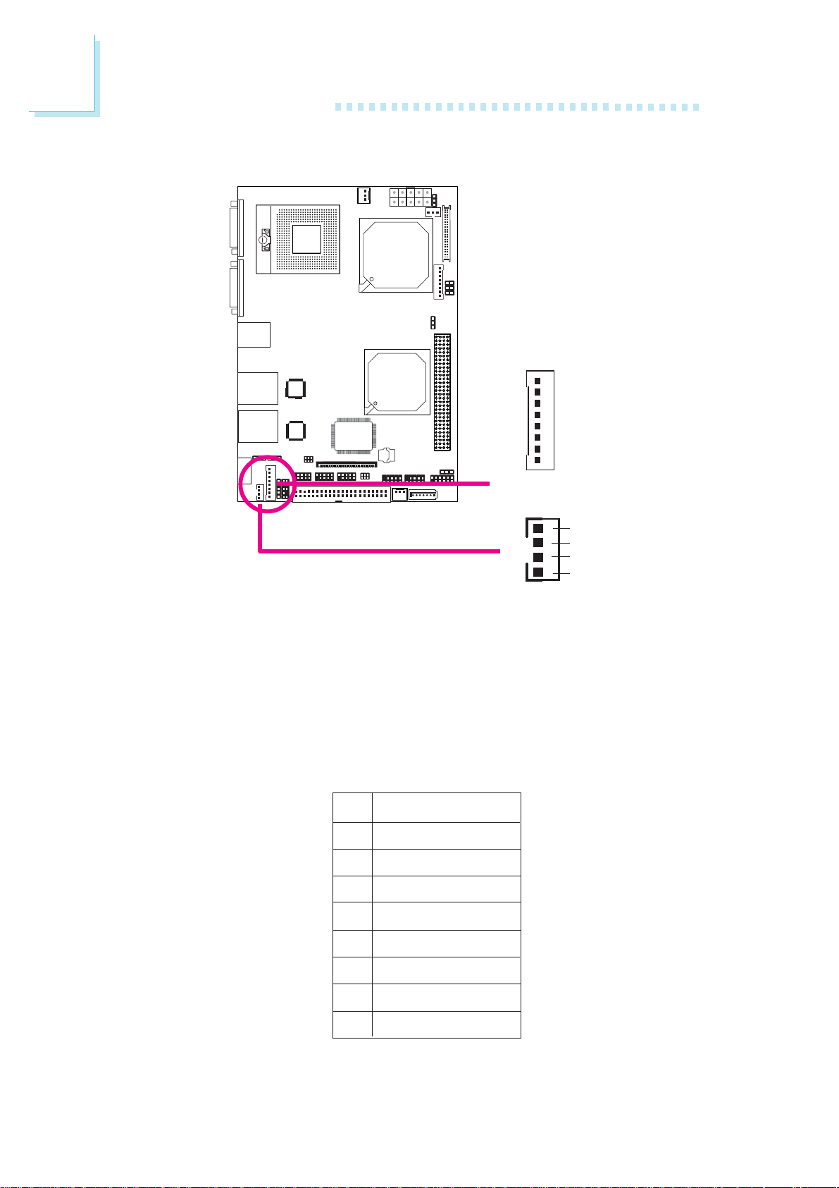
Digital I/O and Digital I/O Power Connectors
Digital I/O
X
1
8
1
X
4
Digital I/O
power
+12V
GND
5VSB
+5V
The Digital I/O connector and Digital I/O power connector provide
powering-on function to an external device that is connected to
these connectors. The Digital I/O bus provides 8-bit write and 8-bit
read.
Digital I/O Connector
Pins
1
2
3
4
Function
DIO0
DIO1
DIO2
DIO3
40
5
6
7
8
DIO4
DIO5
DIO6
DIO7
Page 41
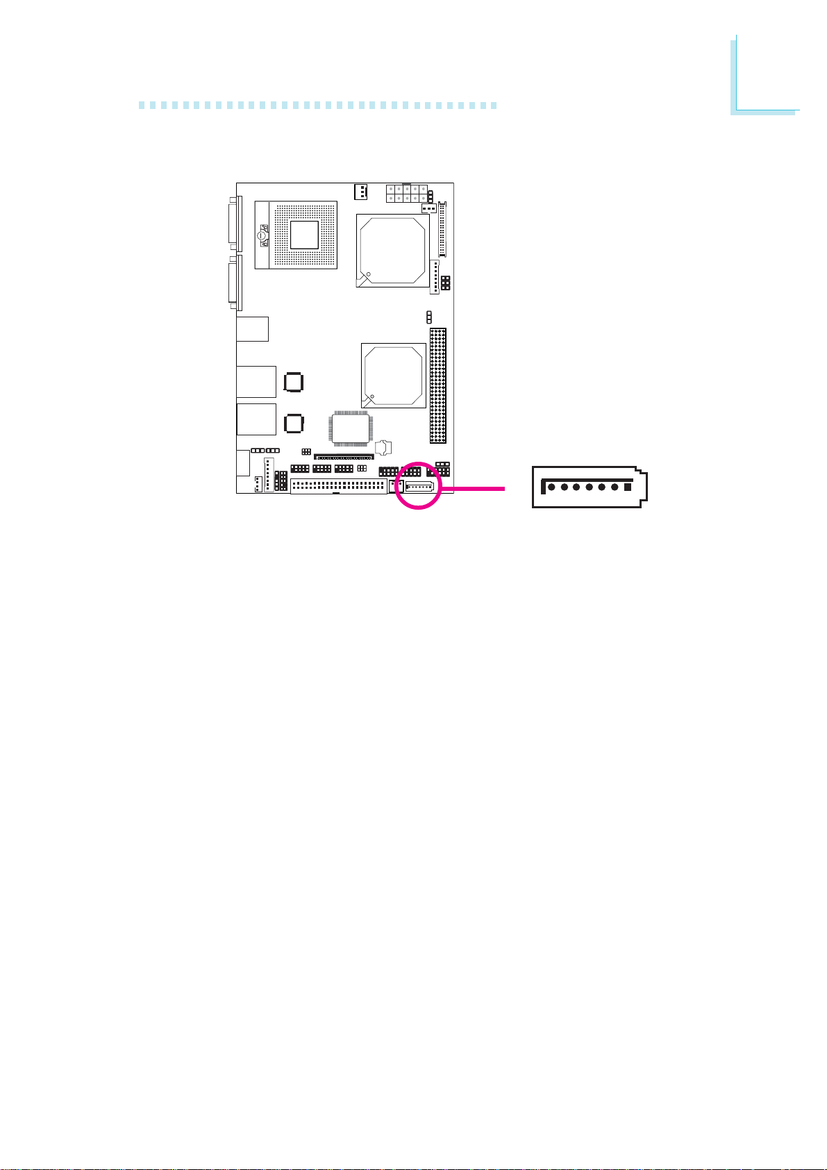
Serial ATA Port
Hardware Installation
2
TXP
GND
1
7
X
RXP
TXN
RXN
GND
GND
The Serial ATA port is used to connect Serial ATA device. Connect
one end of the Serial ATA cable to the SATA port and the other
end to your Serial ATA device.
BIOS Setting
Configure Serial ATA in the Main menu of the BIOS. Refer to chapter
3 for more information.
41
Page 42
2
Hardware Installation
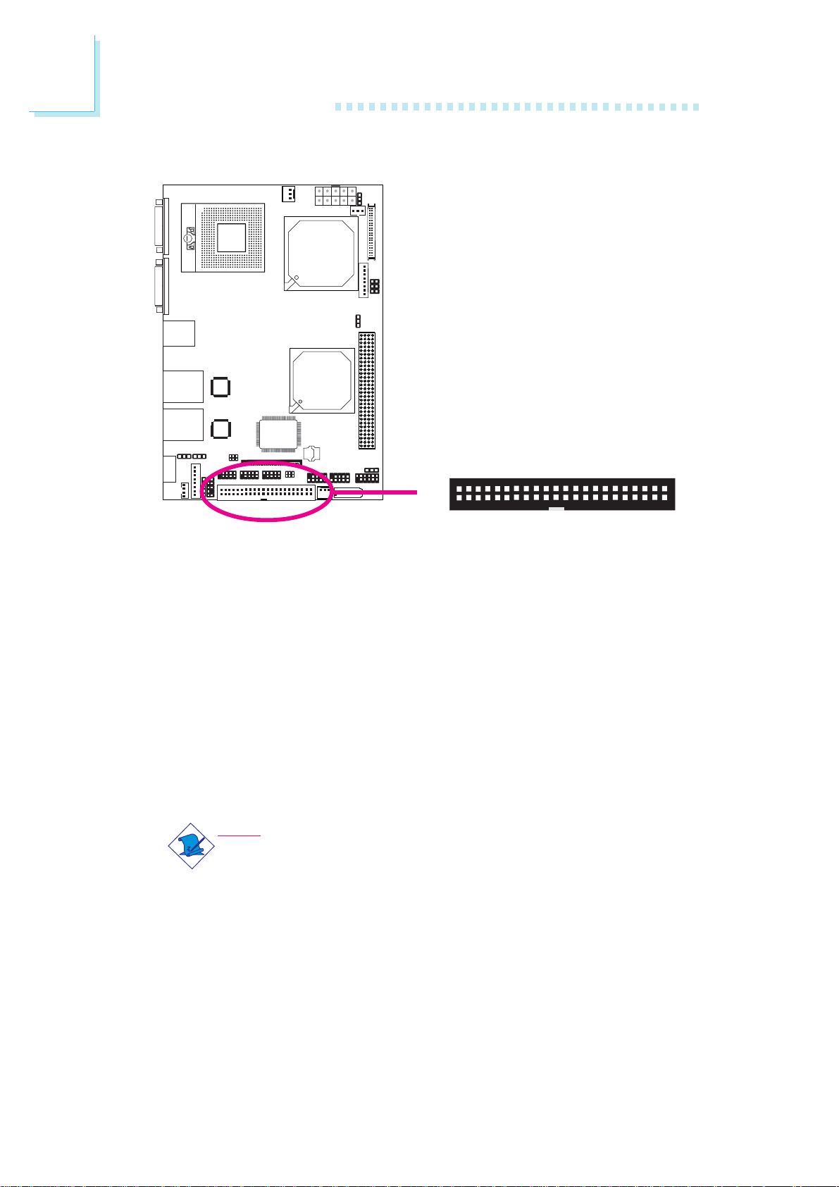
IDE Disk Drive Connectors
2
X
143
The 44-pin IDE connector is used to connect hard drives. The IDE
cable can be inserted into the IDE connector only if pin 1 of the
cable connector is aligned with pin 1 of the IDE connector.
The IDE connector supports 2 devices, a Master and a Slave. Use
an IDE ribbon cable to connect the drives to the system board. An
IDE ribbon cable have 3 connectors on them, one that plugs into an
IDE connector on the system board and the other 2 connects to
IDE devices. The connector at the end of the cable is for the Master
drive and the connector in the middle of the cable is for the Slave
drive.
Note:
We do not recommend using IDE devices and CF card at the
same time.
44
42
Page 43

Hardware Installation
Connecting the IDE Disk Drive Cable
Connect one end of the IDE cable into the IDE connector on the
system board and the other connectors to the IDE devices.
Note:
Refer to your disk drive user’s manual for information about
selecting proper drive switch settings.
Adding a Second IDE Disk Drive
When using two IDE drives, one must be set as the master and the
other as the slave. Follow the instructions provided by the drive
manufacturer for setting the jumpers and/or switches on the drives.
The system board supports Enhanced IDE or ATA-2, ATA/33,
ATA/66 and ATA/100 hard drives. We recommend that you use
hard drives from the same manufacturer. In a few cases, drives from
two different manufacturers will not function properly when used together. The problem lies in the hard drives, not the system board.
2
Important:
If you encountered problems while using an ATAPI CD-ROM
drive that is set in Master mode, please set the CD-ROM drive
to Slave mode. Some ATAPI CD-ROMs may not be recognized
and cannot be used if incorrectly set in Master mode.
BIOS Setting
Configure the onboard IDE in the Main menu of the BIOS. Refer to
chapter 3 for more information.
43
Page 44
2
Hardware Installation
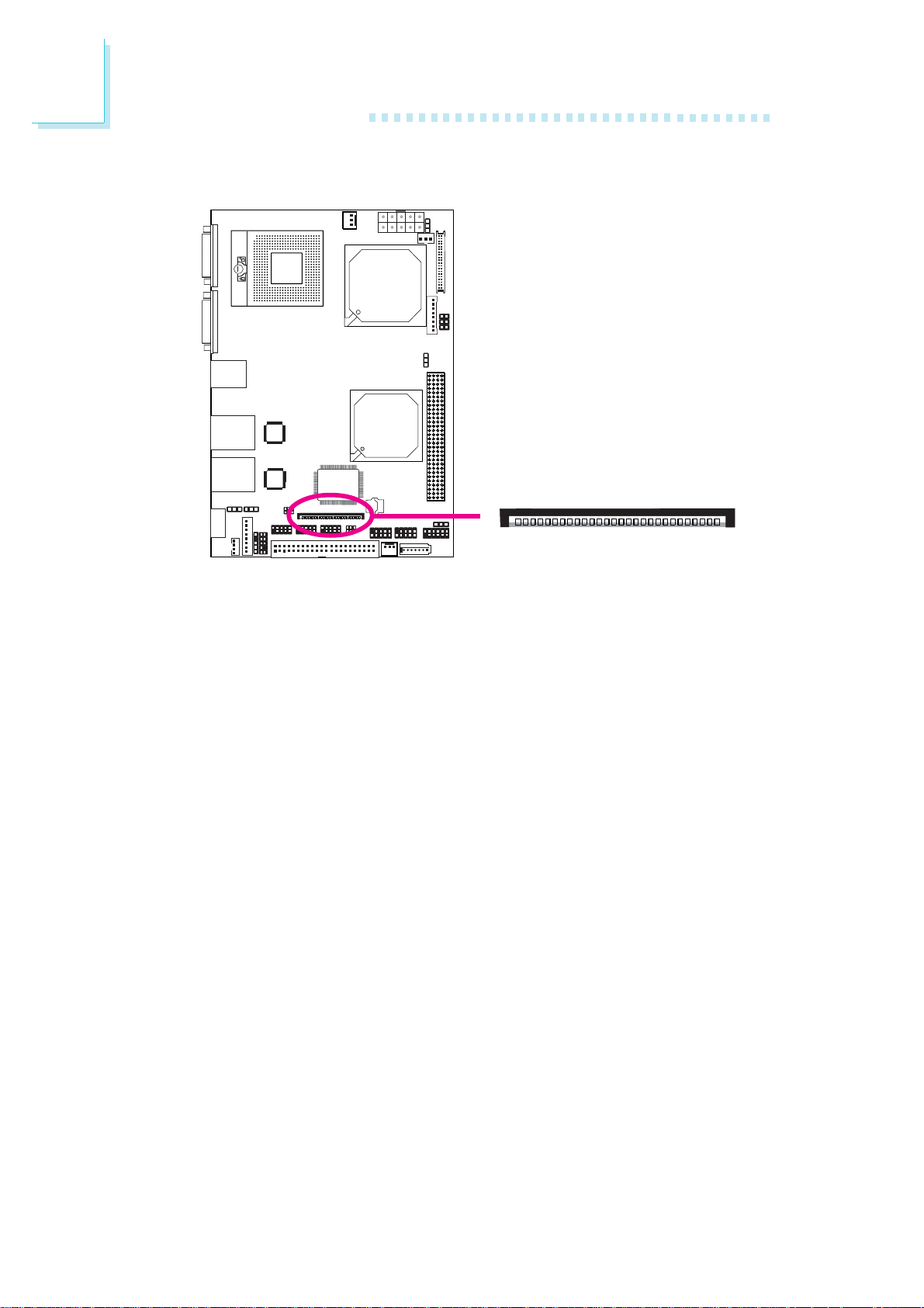
Floppy Disk Drive (FDD) Connector
1
X
The system board is equipped with a 26-pin FPC type floppy disk
drive connector. Only connect a 1.44MB slim-type floppy disk drive.
Floppy drives other than the one mentioned above are optional.
Refer to the next page for the pin function of this connector.
Connecting the Floppy Disk Drive Cable
Install one end of the floppy disk drive cable into the floppy disk
connector on the system board and the other end of the connector
to the floppy drive. Pin 1 of the cable must align with pin 1 of the
FDD connector.
BIOS Setting
Enable or disable this function in the Advanced menu of the BIOS.
Refer to chapter 3 for more information.
44
Page 45

Hardware Installation
FPC Type FDD Connector
2
Pins
1
3
5
7
9
11
13
15
17
19
21
23
25
Function
5V
5V
5V
N. C.
N. C.
N. C.
DRVDE0
GND
GND
GND
GND
GND
GND
Pins
2
4
6
8
10
12
14
16
18
20
22
24
26
Function
INDEX#
DR0#
DSKCH#
N. C.
MTR0#
DIR#
STEP#
WDATA#
WGATE#
TRK0#
WRPRO#
RDATA#
HDSEL#
45
Page 46
2
Hardware Installation
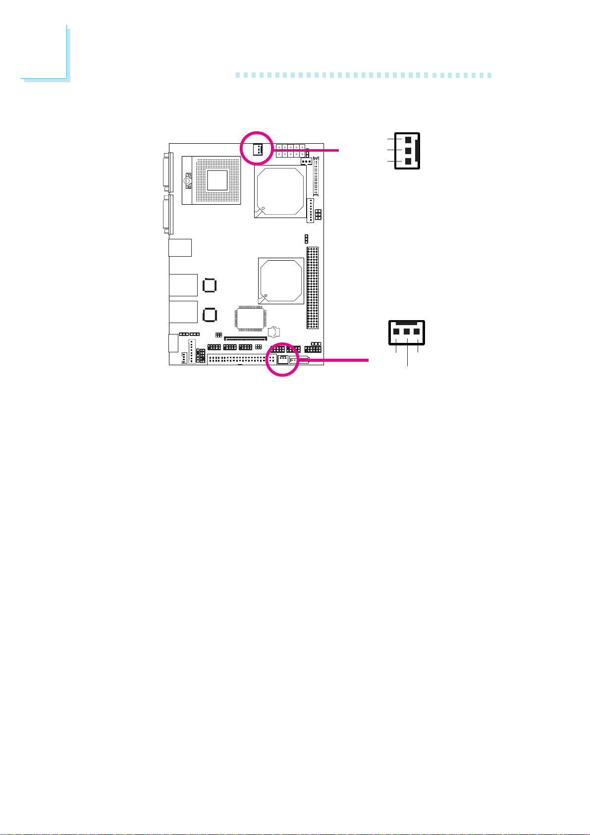
Cooling Fan Connectors
Fan speed
control
Power
X
Ground
3
1
CPU fan
31
N. C.
X
Connect the CPU fan’s cable connector to the CPU fan connector
on the system board. The system fan connector is used to connect
an additional cooling fan. The cooling fans will provide adequate airflow throughout the chassis to prevent overheating the CPU and
system board components.
BIOS Setting
The Advanced menu of the BIOS will display the current speed of
the cooling fans. Refer to chapter 3 for more information.
Ground
Power
System fan
46
Page 47
Power Connector
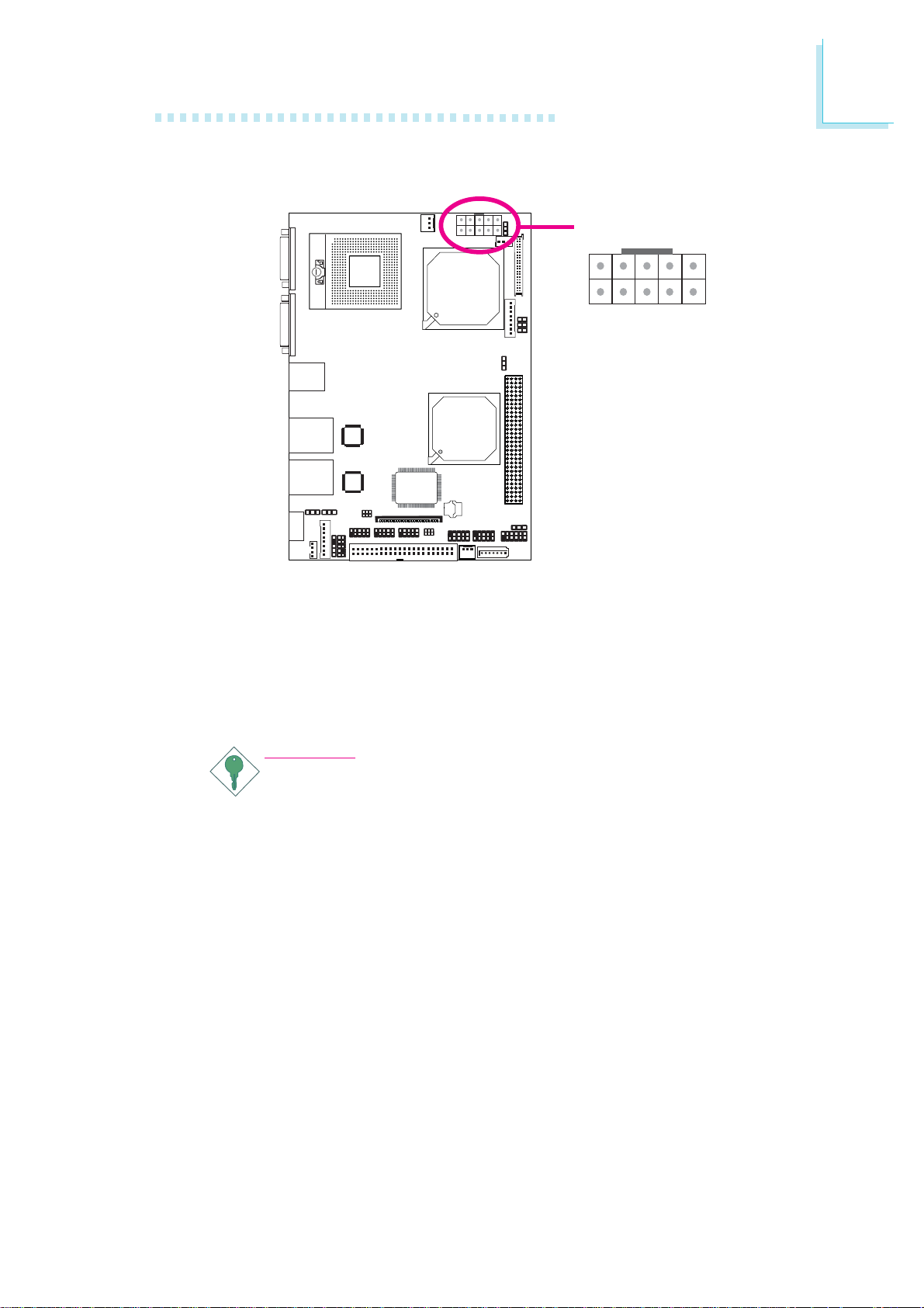
Hardware Installation
2
X
GND
10
5
VCC3
Connect a 10-pin ATX main power connector from the power supply unit to the ATX connector. The system board requires a minimum
of 120 Watt power supply to operate. We recommend that you use
a power supply that complies with the ATX12V Power Supply Design Guide Version 1.1.
VCC
-12V
GND
+12V
VCC
GND
5VSB
6
1
PSON-
Important:
The system board consumes a minimal amount of power. Due
to its low power consumption, you only need a
150W150W
150W power supply. Every power supply has its minimum
150W150W
load of power. If you use a greater than 150W power supply,
the power consumed by the system board may not attain its
minimum load causing instability to the entire system.
120W to120W to
120W to
120W to120W to
47
Page 48
2
Hardware Installation
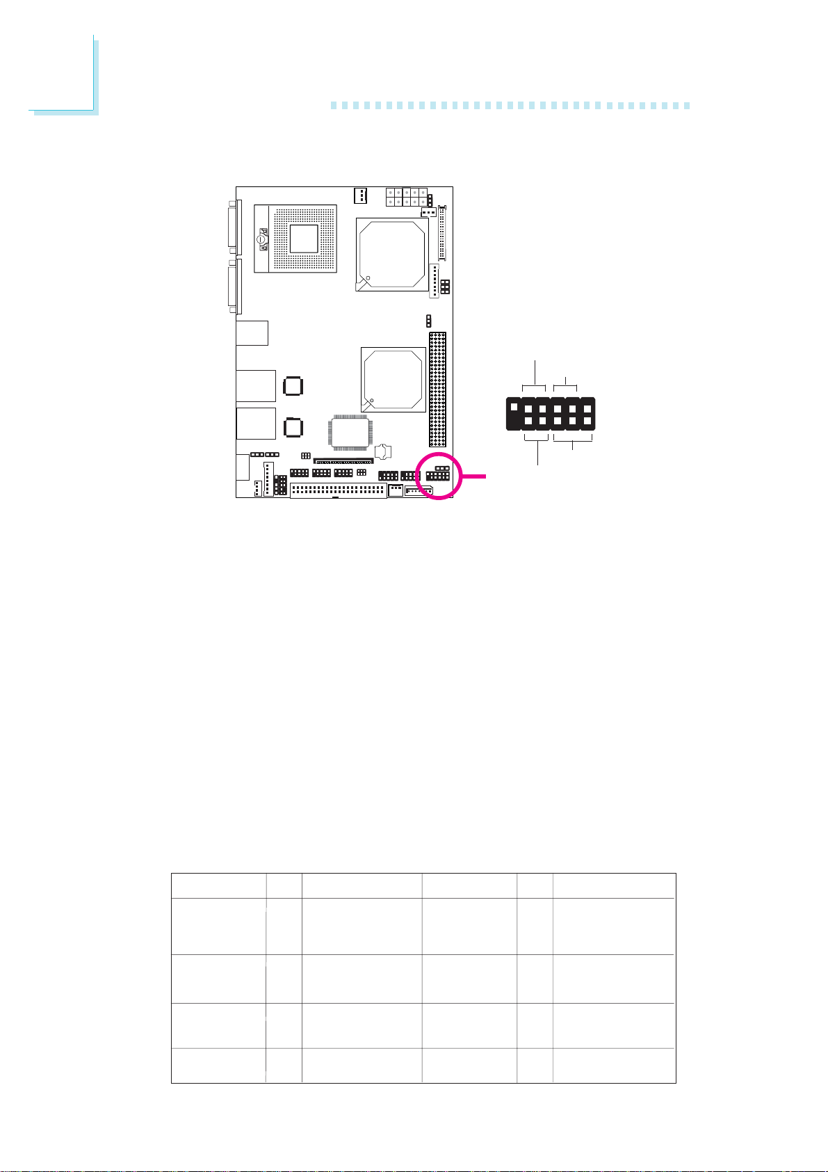
Front Panel Connectors
RESET SW
HDD-LED
11
12
PWR-BTN
X
PWR-LED
1
2
HDD-LED - HDD LED
This LED will light when the hard drive is being accessed.
RESET SW - Reset Switch
This switch allows you to reboot without having to power off the
system.
PWR-BTN - Power Switch
This switch is used to power on or off the system.
PWR-LED - Power/Standby LED
When the system’s power is on, this LED will light. When the system
is in the S1 (POS - Power On Suspend) state, it will blink every
second. When the system is in the S3 (STR - Suspend To RAM)
state, it will blink every 4 seconds.
48
N. C.
HDD-LED
RESET SW
N. C.
Pin Assignment
Pin
N. C.
1
HDD Power
3
5
Signal
Ground
7
9
RST Signal
N. C.
11
PWR-LED
PWR-BTN
Key
Pin Assignment
Pin
LED Power
2
LED Power
4
Signal
6
3V_DUAL
8
Signal
10
Key
12
Page 49
PCI-104 Slot
Hardware Installation
2
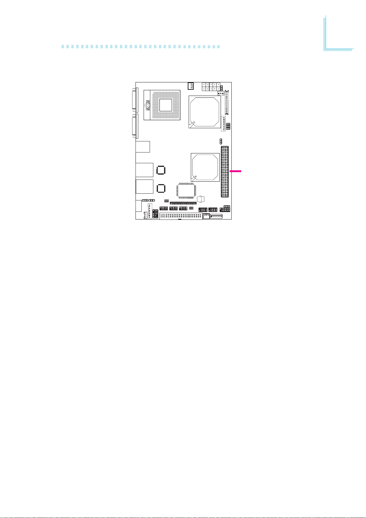
PCI-104 slot
The PCI-104 slot is an interface that allows connecting 4 PCI
devices.
49
Page 50
2
Hardware Installation
CompactFlash Socket
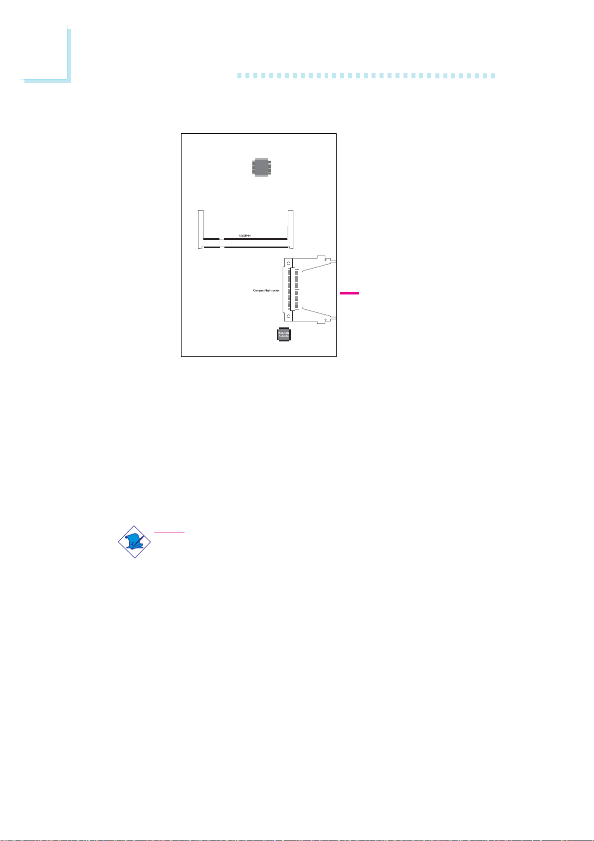
CompactFlash
socket
The system board is equipped with the CompactFlashTM socket for
inserting a CompactFlashTM card. CompactFlashTM card is a small
removable mass storage device designed with flash technology - a
non-volatile storage solution that does not require a battery to re-
TM
tain data indefinitely. The CompactFlash
products such as portable and desktop computers, digital cameras,
handheld data collection scanners, PDAs, Pocket PCs, handy terminals
and personal communicators.
Note:
We do not recommend using IDE devices and CF card at the
same time.
technology is widely used in
50
Page 51

Chapter 3 - BIOS Setup
Overview
The BIOS is a program that takes care of the basic level of communication between the CPU and peripherals. It contains codes for various advanced features found in this system board. The BIOS allows
you to configure the system and save the configuration in a batterybacked CMOS so that the data retains even when the power is off.
In general, the information stored in the CMOS RAM of the
EEPROM will stay unchanged unless a configuration change has been
made such as a hard drive replaced or a device added.
It is possible that the CMOS battery will fail causing CMOS data
loss. If this happens, you need to install a new CMOS battery and
reconfigure the BIOS settings.
BIOS Setup
3
Note:
The BIOS is constantly updated to improve the performance of
the system board; therefore the BIOS screens in this chapter
may not appear the same as the actual one. These screens
are for reference purpose only.
Default Configuration
Most of the configuration settings are either predefined according to
the Load Optimal Defaults settings which are stored in the BIOS or
are automatically detected and configured without requiring any actions. There are a few settings that you may need to change depending on your system configuration.
Entering the BIOS Setup Utility
The BIOS Setup Utility can only be operated from the keyboard and
all commands are keyboard commands. The commands are available
at the right side of each setup screen.
The BIOS Setup Utility does not require an operating system to run.
After you power up the system, the BIOS message appears on the
screen and the memory count begins. After the memory test, the
message “Press DEL to enter setup” will appear on the screen. If the
51
Page 52

3
BIOS Setup
message disappears before you respond, restart the system or press
the “Reset” button. You may also restart the system by pressing the
<Ctrl> <Alt> and <Del> keys simultaneously.
Legends
Keys
Right and Left arrows
Up and Down arrows
<Esc>
+ (plus key)
- (minus key)
Ta b
<F1>
<F10>
<Enter>
Function
Moves the highlight left or right to select
a menu.
Moves the highlight up or down between
submenus or fields.
Exits to the BIOS Setup Utility.
Scrolls forward through the values or options of the highlighted field.
Scrolls backward through the values or
options of the highlighted field.
Selects a field.
Displays General Help.
Saves and exits the Setup program.
Press <Enter> to enter the highlighted
submenu.
Scroll Bar
When a scroll bar appears to the right of the setup screen, it indicates that there are more available fields not shown on the screen.
Use the up and down arrow keys to scroll through all the available
fields.
Submenu
When “ “ appears on the left of a particular field, it indicates that a
X
submenu which contains additional options are available for that field.
To display the submenu, move the highlight to that field and press
<Enter>.
52
Page 53

Main
BIOS Setup
The Main menu is the first screen that you will see when you enter
the BIOS Setup Utility.
BIOS SETUP UTILITY
Main
Advanced PCIPnP Boot Security
ExitChipset
3
System Date
System Time
ATA/IDE Configuration
Configure SATA as
X
Primary IDE Master
X
Primary IDE Slave
X
Secondary IDE Master
X
Secondary IDE Slave
X
Tertiary IDE Master
X
Tertiary IDE Slave
IDE Detect Time Out (Sec)
Floppy A
X
System Information
System Date
The date format is <day>, <month>, <date>, <year>. Day displays
a day, from Sunday to Saturday. Month displays the month, from
January to December. Date displays the date, from 1 to 31. Year
displays the year, from 1999 to 2099.
[Tue 11/27/2007]
9 : 3 : 54
[Enhanced]
[IDE]
[Hard Disk]
[Not Detected]
[Not Detected]
[Not Detected]
[ATAPI CDROM]
[Not Detected]
[35]
[Disabled]
v02.61 (C)Copyright 1985-2006, American Megatrends, Inc.
Use [ENTER] to select
a field.
Use [+] or [-] to
configure system Date.
← → Select Screen
↑↓ Select Item
+
Tab Select Field
F1 General Help
F10 Save and Exit
ESC Exit
-
Change Field
System Time
The time format is <hour>, <minute>, <second>. The time is based
on the 24-hour military-time clock. For example, 1 p.m. is 13:00:00.
Hour displays hours from 00 to 23. Minute displays minutes from
00 to 59. Second displays seconds from 00 to 59.
ATA/IDE Configuration
This field is used to configure the IDE drives. The options are Disabled, Compatible and Enhanced.
53
Page 54
3
BIOS Setup
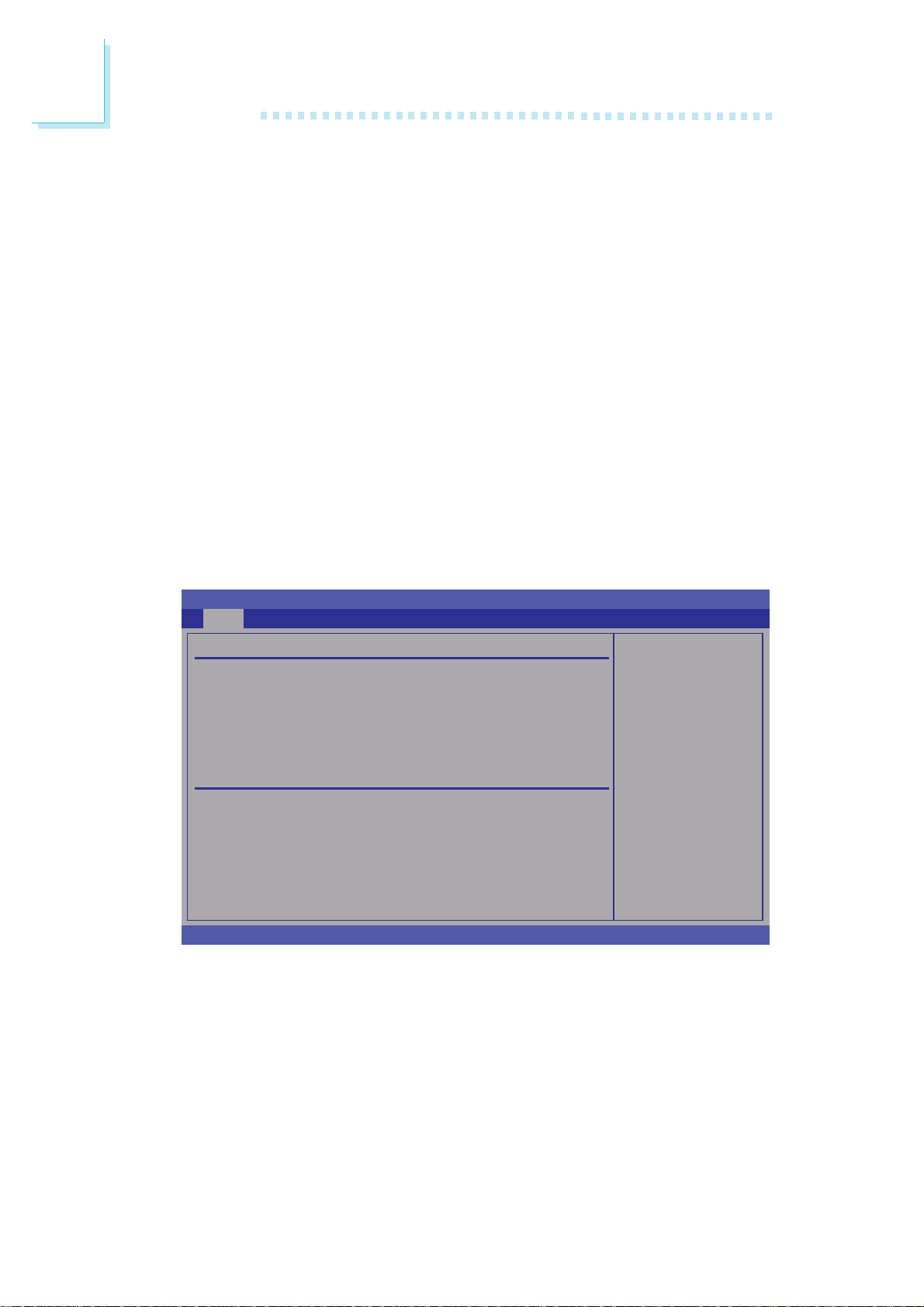
Configure SATA As
IDE This option configures the Serial ATA drives as Parallel
ATA physical storage device.
AHCI This option configures the Serial ATA drives to use AHCI
(Advanced Host Controller Interface). AHCI allows the
storage driver to enable the advanced Serial ATA features
which will increase storage performance.
Primary IDE Master to Tertiary IDE Slave
When you enter the BIOS Setup Utility, the BIOS will auto detect
the existing IDE devices then display the status of the detected devices.
To configure an IDE drive, move the cursor to a field then press
<Enter>. The parameters of the drive will appear on the screen.
BIOS SETUP UTILITY
Main
Primary IDE Master
Device : Hard Disk
Vendor : ST380811AS
Size : 80.0GB
LBA Mode : Supported
Block Mode : 16 Sec to rs
PIO Mode : 4
Async DMA : MultiWord DMA-2
Ultra DMA : Ultra DMA-6
S.M.A.R.T. : Supported
Type [Auto]
PIO Mode [Auto]
DMA Mode [Auto]
S.M.A.R.T. [Auto]
32Bit Data Transfer [Enabled]
v02.61 (C)Copyright 1985-2006, American Megatrends, Inc.
Type
Selects the type of IDE drive.
Select the type
of device connected
to the system.
← → Select Screen
↑↓ Select Item
-
+
Change Option
F1 General Help
F10 Save and Exit
ESC Exit
54
Page 55

BIOS Setup
PIO Mode
Selects the data transfer mode. PIO means Programmed Input/Output. Rather than have the BIOS issue a series of commands to effect
a transfer to or from the disk drive, PIO allows the BIOS to tell the
controller what it wants and then let the controller and the CPU
perform the complete task by themselves. Your system supports five
modes, 0 (default) to 4, which primarily differ in timing. When Auto is
selected, the BIOS will select the best available mode after checking
your drive.
Auto The BIOS will automatically set the system according
to your hard disk drive’s timing.
Mode 0-4 You can select a mode that matches your hard disk
drive’s timing. Caution: Do not use the wrong setting
or you will have drive errors.
3
DMA Mode
Selects the DMA mode.
S.M.A.R.T.
The system board supports SMART (Self-Monitoring, Analysis and
Reporting Technology) hard drives. SMART is a reliability prediction
technology for ATA/IDE and SCSI drives. The drive will provide sufficient notice to the system or user to backup data prior to the
drive’s failure. SMART is supported in ATA/33 or later hard drives.
The options are Auto (default), Enabled and Disabled.
32Bit Data Transfer
Enables or disables 32-bit data transfer.
55
Page 56
3
BIOS Setup
IDE Detect Time Out (Sec)
Selects the time out value for detecting ATA/ATAPI devices.
Floppy A
This field identifies the type of floppy disk drive installed.
None No floppy drive is installed
360K, 5.25 in. 5-1/4 in. standard drive; 360KB capacity
1.2M, 5.25 in. 5-1/4 in. AT-type high-density drive; 1.2MB
capacity
720K, 3.5 in. 3-1/2 in. double-sided drive; 720KB capacity
1.44M, 3.5 in. 3-1/2 in. double-sided drive; 1.44MB capacity
2.88M, 3.5 in. 3-1/2 in. double-sided drive; 2.88MB capacity
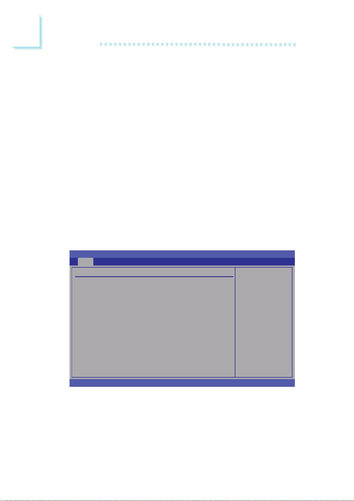
System Information
This section displays general system specifications. The BIOS automatically detects the information in this section.
BIOS SETUP UTILITY
Main
System Information
Model Name : SR100N
Firmware Information
BIOS File Name : SR100N77.25A, 07/26/2007
System Memory Information
T otal 504MB
DIMM-1 None
DIMM-2 512MB
← → Select Screen
↑↓ Select Item
F1 General Help
F10 Save and Exit
ESC Exit
v02.61 (C)Copyright 1985-2006, American Megatrends, Inc.
56
Firmware Information
Displays the detected BIOS information.
System Memory Information
Displays the detected system memory.
Page 57
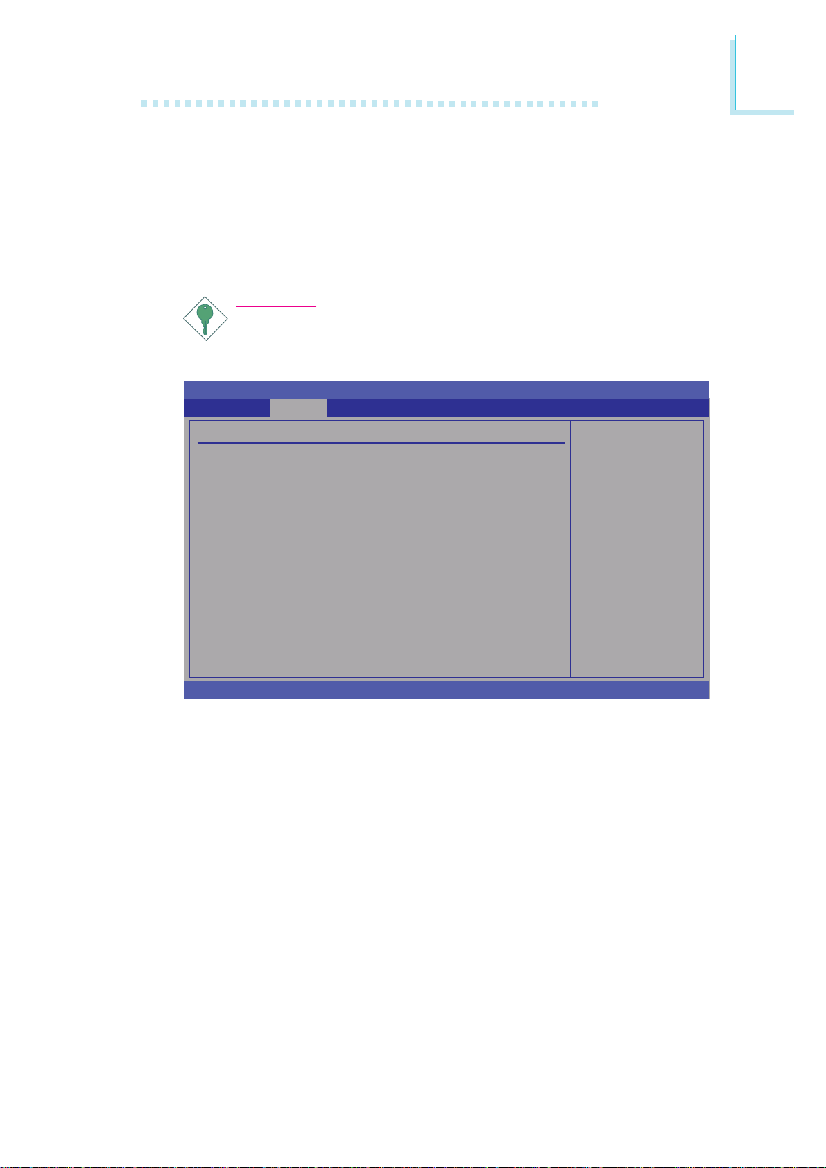
Advanced
The Advanced menu allows you to configure your system for basic
operation. Some entries are defaults required by the system board,
while others, if enabled, will improve the performance of your system
or let you set some features according to your preference.
BIOS Setup
Important:
Setting incorrect field values may cause the system to malfunction.
BIOS SETUP UTILITY
PCIPnP Boot SecurityMain Advanced
ExitChipset
3
Advanced Settings
WARNING: Setting wrong values in below sections
X
CPU Configuration
X
Super IO Configuration
X
PC Health Status
X
ACPI Configuration
X
APM Configuration
X
MPS Configuration
X
USB Configuration
may cause system to malfunction.
v02.61 (C)Copyright 1985-2006, American Megatrends, Inc.
Configure CPU.
← → Select Screen
↑↓ Select Item
Enter Go to Sub Screen
F1 General Help
F10 Save and Exit
ESC Exit
57
Page 58
3
BIOS Setup
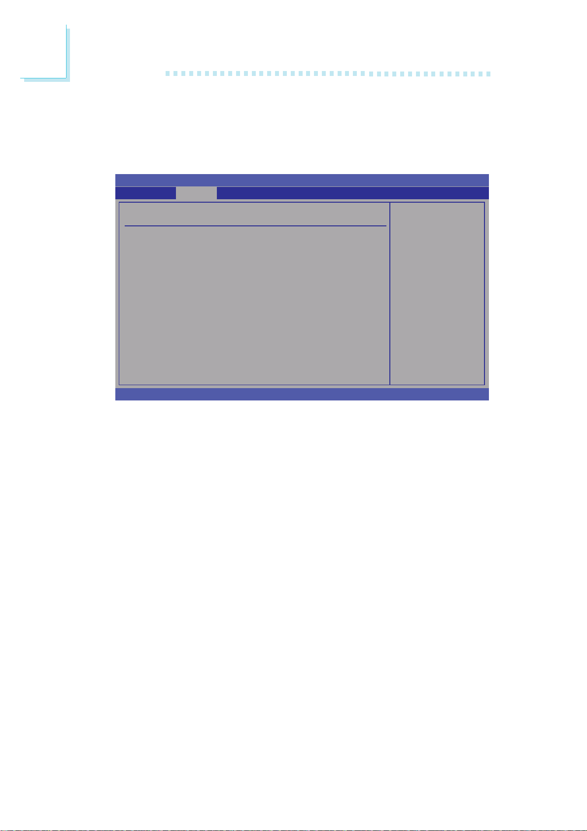
CPU Configuration
This section is used to configure the CPU. It will also display detected CPU information.
BIOS SETUP UTILITY
Advanced
Configure advanced CPU settings
Module Version:3E.02
Manufacturer : Intel
Intel(R) Core(TM)2 Duo CPU T7700 @ 2.40GHz
Frequency : 2.40GHz
FSB Speed : 800MHz
Cache L1 : 64 KB
Cache L2 : 4096 KB
Hardware Prefetcher [Enabled]
Adjacent Cache Line Prefetch [Enabled]
Max CPUID Value Limit [Disabled]
Vanderpool Technology [Enabled]
Execute Disable Bit [Enabled]
Core Multi-Processing [Enabled]
Intel(R) SpeedStep(TM) tech [Enabled]
Intel(R) C-STATE tech [Enabled]
Enhanced C-States [Enabled]
v02.61 (C)Copyright 1985-2006, American Megatrends, Inc.
Hardware Prefetcher
Enables or disables the Hardware Prefetcher feature.
Adjacent Cache Line Prefetch
This should be enabled
in order to enable or
disable the Hardware
Prefetcher Disable
Feature.
← → Select Screen
↑↓ Select Item
-
+
Change Field
F1 General Help
F10 Save and Exit
ESC Exit
Enables or disables the Adjacent Cache Line Prefetch feature.
Max CPUID Value Limit
Set this field to Disabled when using Windows XP. Set this field to
Enabled when using legacy operating systems so that the system will
boot even when it doesn’t support CPUs with extended CPUID
function.
Vanderpool Technology
Set this field to Enabled when the processor supports Vanderpool
technology.
58
Page 59

BIOS Setup
Execute Disable Bit
When this field is set to Disabled, it will force the XD feature flag to
always return to 0.
Core Multi-Processing
The options are Enabled and Disabled. Disabling this field disables
one execution core.
Intel(R) SpeedStep(TM) Tech
Enables or disables GV3.
Intel(R) C-STATE Tech
CPU Idle is set to C2, C3, C4 state.
3
Enhanced C-States
CPU Idle is set to Enhanced C-State.
59
Page 60
3
BIOS Setup
Super IO Configuration
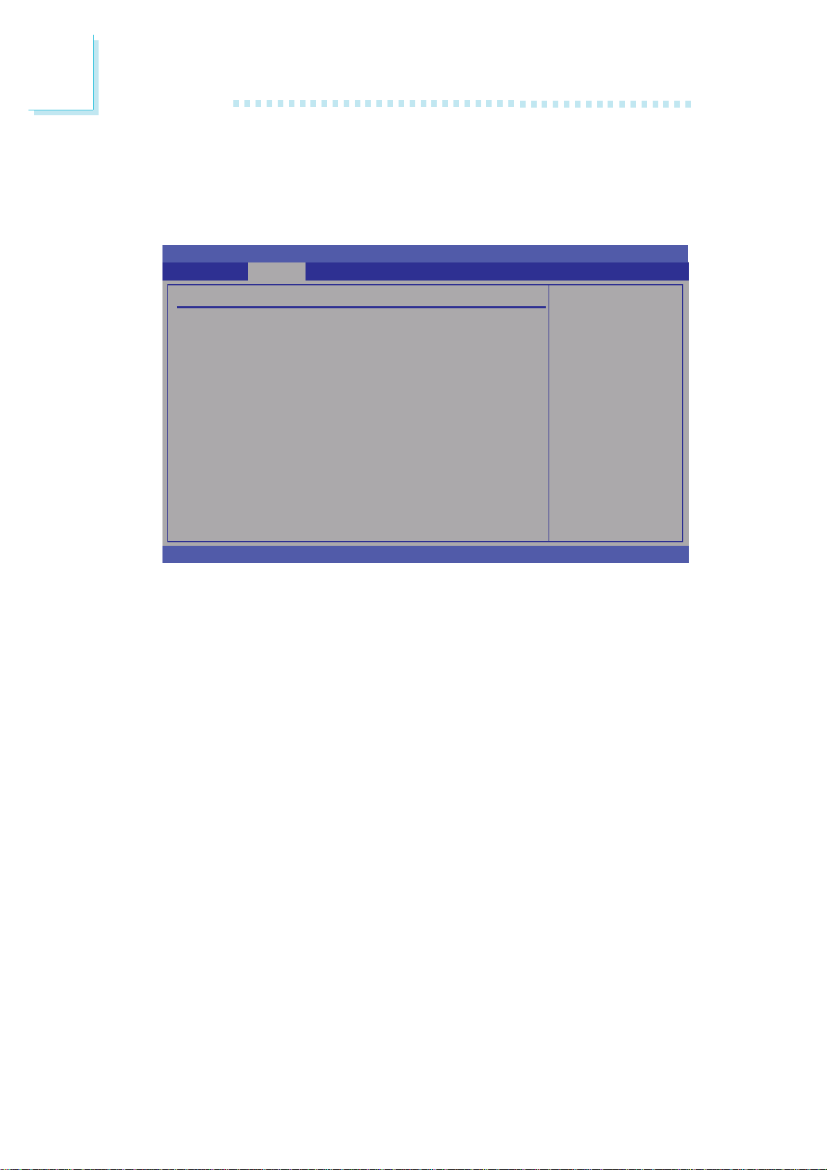
This section is used to configure the I/O functions supported by the
onboard Super I/O chip.
BIOS SETUP UTILITY
Advanced
Super IO Configuration
Onboard Floppy Controller [Enabled]
Onboard IrDA Controller [A98/IRQ3]
IR Duplex Mode [Half Duplex]
Serial Port1 Address [3F8]
Serial Port1 IRQ [11]
Serial Port2 Address [2F8]
Serial Port2 IRQ [10]
Serial Port3 Address [3E8]
Serial Port3 IRQ [11]
Serial Port4 Address [2E8]
Serial Port4 IRQ [10]
v02.61 (C)Copyright 1985-2006, American Megatrends, Inc.
Allows BIOS to select
Serial Port1 Base
Addresses.
← → Select Screen
↑↓ Select Item
-
+
Change Option
F1 General Help
F10 Save and Exit
ESC Exit
Onboard Floppy Controller
This field is used to enable or disable the onboard floppy controller.
Onboard IrDA Controller
This field is used to select an address for the IrDA controller.
IR Duplex Mode
Half Duplex Data is completely transmitted before receiving data.
Full Duplex Transmits and receives data simultaneously.
Serial Port1 Address to Serial Port4 Address
This field is used to select an address for a serial port.
Serial Port1 IRQ to Serial Port4 IRQ
This field is used to select an IRQ for a serial port.
60
Page 61
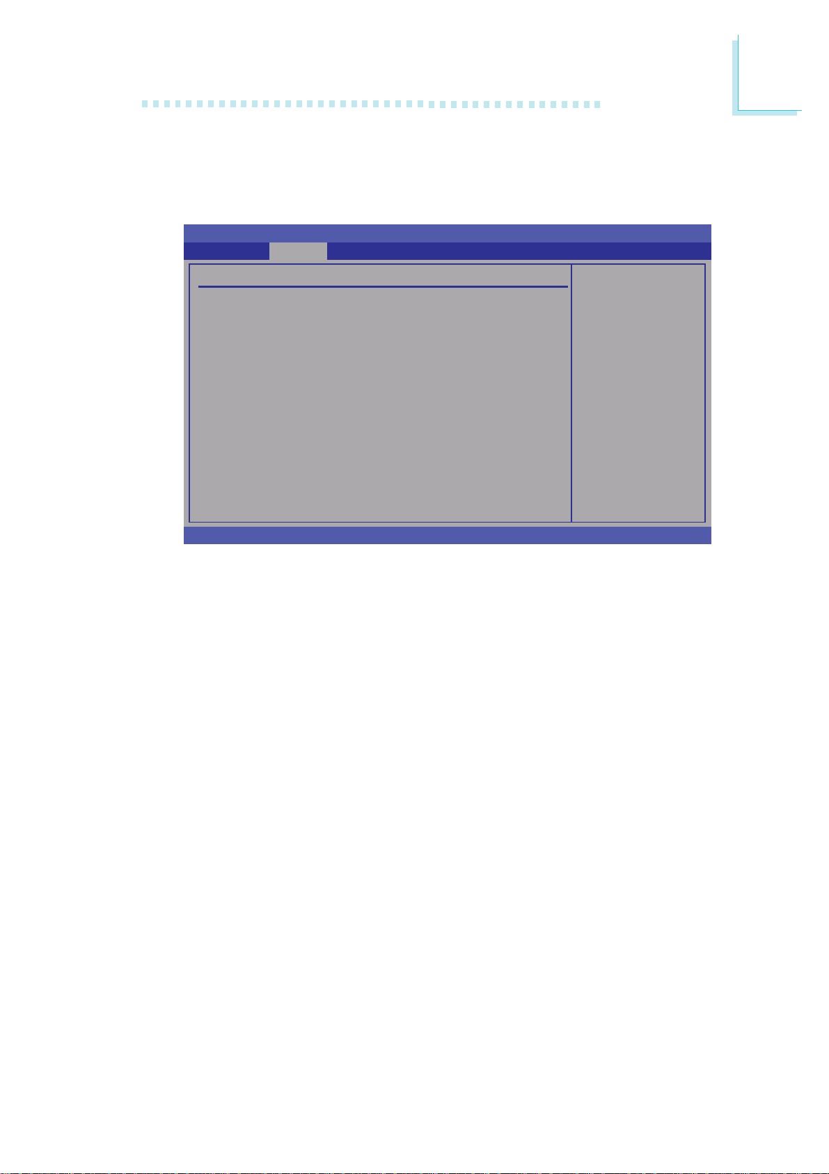
PC Health Status
This section is used to configure the hardware monitor function.
PC Health Status
Current System Temp : 29oC/84oF
Current CPU Temperature : 61oC/141oF
System Fan : NA
CPU Fan : 7031 RPM
Vcore : 1.088 V
+3.3V : 3.232 V
+12V : 11.932 V
+1.5V : 1.512 V
+1.8V : 1.848 V
+5 V : 4.992 V
VBAT (V) : 3.184 V
BIOS Setup
3
BIOS SETUP UTILITY
Advanced
← → Select Screen
↑↓ Select Item
F1 General Help
F10 Save and Exit
ESC Exit
v02.61 (C)Copyright 1985-2006, American Megatrends, Inc.
Current System Temp and Current CPU Temperature
Detects and displays the internal temperature of the system and the
current temperature of the CPU.
System Fan and CPU Fan
Detects and displays the current system fan and CPU fan speed in
RPM (Revolutions Per Minute).
Vcore to VBAT (V)
Detects and displays the output voltages.
61
Page 62
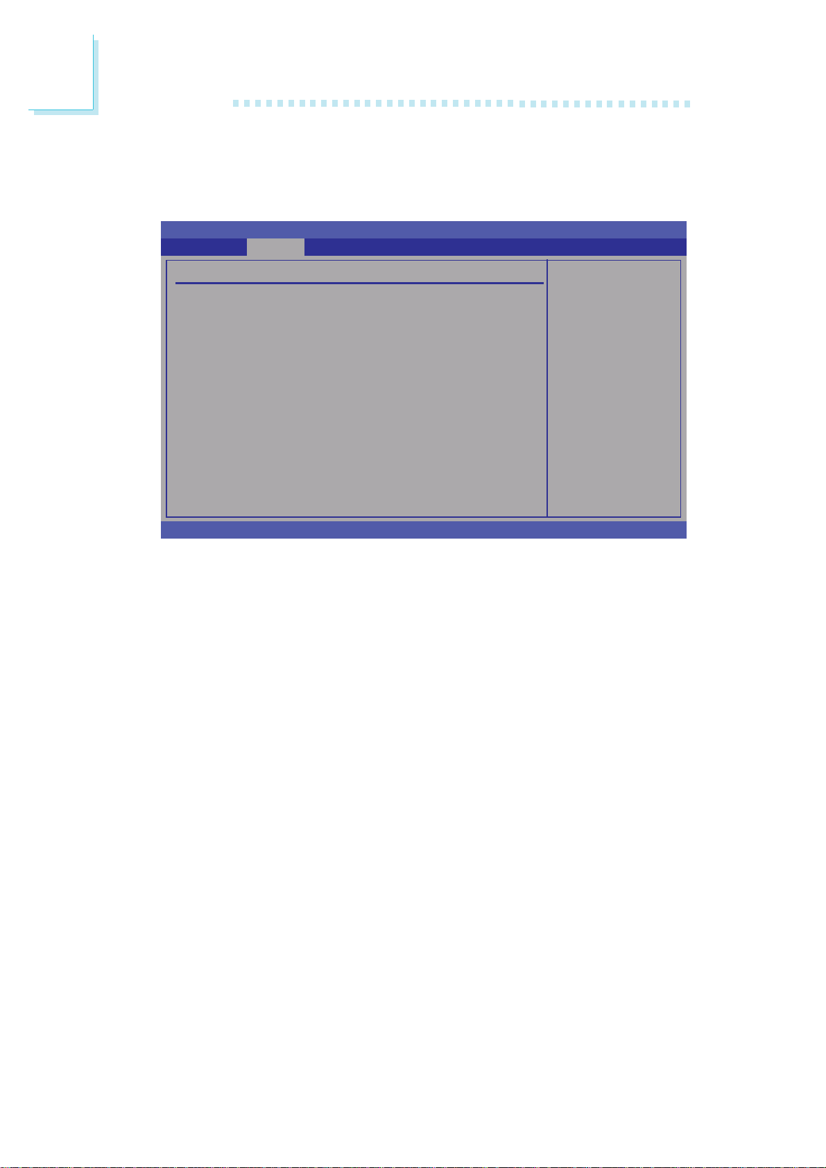
3
BIOS Setup
ACPI Configuration
This section is used to configure the Advanced ACPI configuration.
BIOS SETUP UTILITY
Advanced
ACPI Settings
ACPI Version Features [ACPI v1.0]
ACPI APIC Support [Enabled]
ACPI Standby State [S1 (POS)]
v02.61 (C)Copyright 1985-2006, American Megatrends, Inc.
ACPI Version Features
Selects the ACPI version.
ACPI APIC Support
Enable RSDP pointers
to 64-bit Fixed System
Description Tables.
← → Select Screen
↑↓ Select Item
-
+
Change Option
F1 General Help
F10 Save and Exit
ESC Exit
Enables or disables the Advanced Configuration and Power Interface
(ACPI) of the Advanced Programmable Interrupt Controller (APIC).
When enabled, the ACPI APIC table pointer is included in the RSDT
pointer list.
ACPI Standby State
Selects the ACPI state to be used for system suspend.
S1(POS) Enables the Power On Suspend function.
S3(STR) Enables the Suspend to RAM function.
62
Page 63
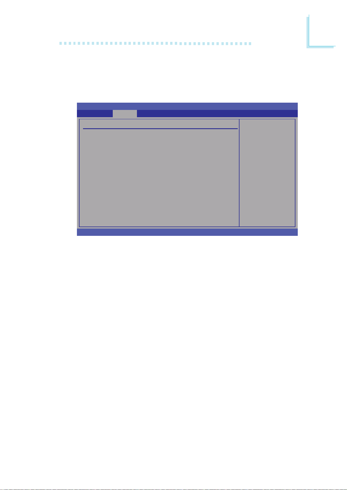
APM Configuration
This section is used to configure your system to most effectively save
energy.
Advanced
BIOS Setup
3
BIOS SETUP UTILITY
APM Configuration
Power Management/APM [Enabled]
Video Power Down Mode [Suspend]
Hard Disk Power Down Mode [Suspend]
Suspend Time Out (Minute) [Disa bled]
Keyboard & PS/2 Mouse [Monitor]
Power Button Function [On/Off]
Advanced Resume Event Controls
Resume On PS2 Keyboard [Disabled]
Resume On PS2 Mouse [Disabled]
Resume On Onboard LAN [Disabled]
Resume On Ring [Disa bled]
Resume By RTC [Dis abled]
Restore on AC Power Loss [Power Off]
v02.61 (C)Copyright 1985-2006, American Megatrends, Inc.
Power Management/APM
Enables or disables APM.
Video Power Down Mode
Enable or disable APM.
← → Select Screen
↑↓ Select Item
-
+
Change Option
F1 General Help
F10 Save and Exit
ESC Exit
Suspend Activates the video off feature when the system en-
ters the Suspend mode.
Disabled Disables the video off feature.
Hard Disk Power Down Mode
Suspend Activates the hard disk power down feature when
the system enters the Suspend mode.
Disabled Disables the hard disk power down feature.
Suspend Time Out (Minute)
Selects the time that the system enters the Suspend mode.
Keyboard & PS/2 Mouse
Monitors PS/2 keyboard and PS/2 mouse ports.
63
Page 64

3
BIOS Setup
Power Button Function
On/Off When the power button is pressed, it turns the sys-
tem on or off.
Suspend When the power button is pressed, the system goes
into Suspend mode.
Resume On PS2 Keyboard
Enables the PS/2 keyboard to wake up the system.
Resume On PS2 Mouse
Enables the PS/2 mouse to wake up the system.
Resume On Onboard LAN
Enables the LAN to wake up the system.
Resume On Ring
Enables the system to wake up to respond to calls coming from an
external modem.
Resume By RTC
Enables the RTC to wake up the system.
Restore on AC Power Loss
Power Off When power returns after an AC power failure, the
system’s power is off. You must press the Power button
to power-on the system.
Power On When power returns after an AC power failure, the
system will automatically power-on.
Last State When power returns after an AC power failure, the
system will return to the state where you left off before
power failure occurs. If the system’s power is off when
AC power failure occurs, it will remain off when power
returns. If the system’s power is on when AC power
failure occurs, the system will power-on when power
returns.
64
Page 65
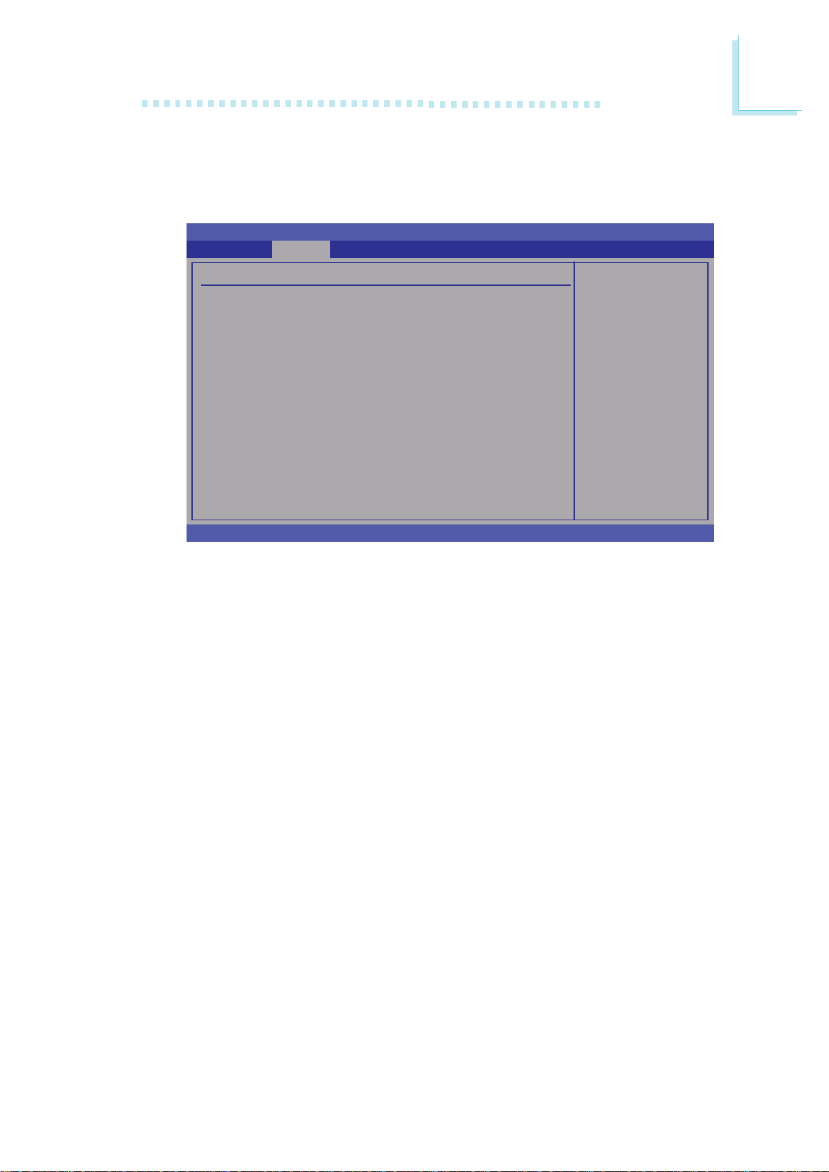
MPS Configuration
This section is used to configure the multi-processor table.
BIOS Setup
3
BIOS SETUP UTILITY
Advanced
MPS Configuration
MPS Revision [1.4]
v02.61 (C)Copyright 1985-2006, American Megatrends, Inc.
MPS Revision
Selects the MPS revision used by the system.
Select MPS Revision.
← → Select Screen
↑↓ Select Item
-
+
Change Option
F1 General Help
F10 Save and Exit
ESC Exit
65
Page 66
3
BIOS Setup
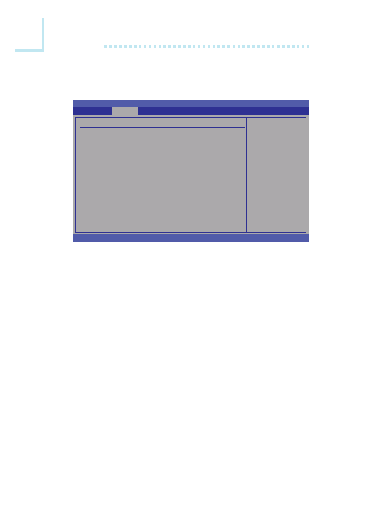
USB Configuration
This section is used to configure USB devices.
BIOS SETUP UTILITY
Advanced
USB Configuration
Module Version - 2.24.2-13.4
USB Devices Enabled :
Legacy USB Support [Enabled]
USB 2.0 Controller Mode [HiSpeed]
BIOS EHCI Hand-Off [Enabled]
Hotplug USB FDD Support [Auto]
X
USB Mass Storage Device Configuration
None
v02.61 (C)Copyright 1985-2006, American Megatrends, Inc.
Enables support for
legacy USB. Auto
option disables
legacy support if
no USB devices are
connected.
← → Select Screen
↑↓ Select Item
-
+
Change Option
F1 General Help
F10 Save and Exit
ESC Exit
Legacy USB Support
Due to the limited space of the BIOS ROM, the support for legacy
USB keyboard (in DOS mode) is by default set to Disabled. With
more BIOS ROM space available, it will be able to support more
advanced features as well as provide compatibility to a wide variety
of peripheral devices.
66
If a PS/2 keyboard is not available and you need to use a USB
keyboard to install Windows (installation is performed in DOS
mode) or run any program under DOS, set this field to Enabled.
USB 2.0 Controller Mode
Sets the USB 2.0 controller mode to HiSpeed (480 Mbps) or
FullSpeed (12 Mbps).
BIOS EHCI Hand-Off
Enable this field when using operating systems without the EHCI
hand-off support.
Page 67
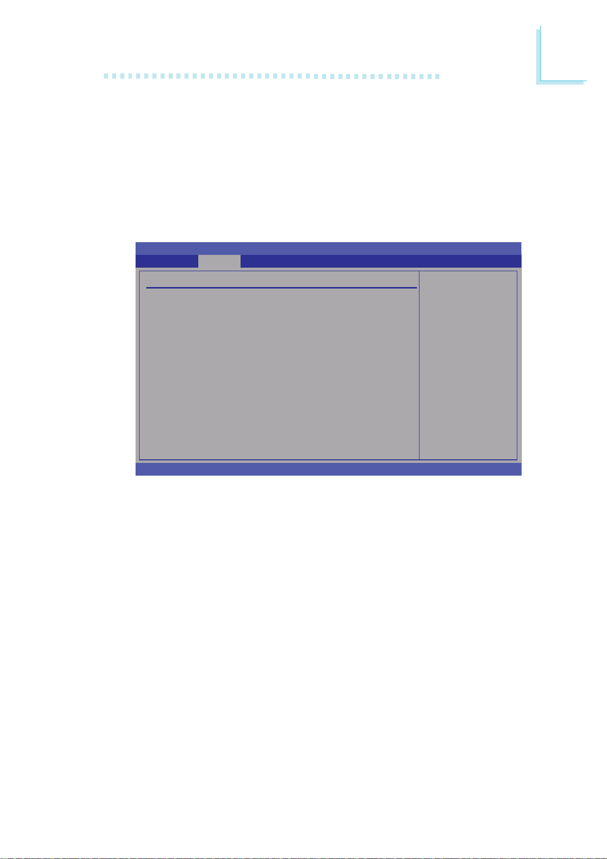
Hotplug USB FDD Support
If no USB FDD is present, a dummy FDD device is created that will
be associated with the hotplugged FDD later.
USB Mass Storage Device Configuration
This section is used to configure the USB mass storage devices.
BIOS SETUP UTILITY
Advanced
BIOS Setup
3
USB Mass Storage Device Configuration
USB Mass Storage Reset Delay [20 Sec]
Device #1 USB Hotplug FDD
Emulation Type [Auto]
v02.61 (C)Copyright 1985-2006, American Megatrends, Inc.
Number of seconds
POST waits for the
USB mass storage
device after start
unit command.
← → Select Screen
↑↓ Select Item
-
+
Change Option
F1 General Help
F10 Save and Exit
ESC Exit
USB Mass Storage Reset Delay
Selects the number of seconds POST waits for the USB mass storage device after the start of a unit command.
Emulation Type
Auto USB devices less than 530MB will be emulated as
floppy while the rest as hard drive.
Floppy Emulates the USB flash disk as floppy.
Forced FDD Forces an HDD formatted drive to boot as FDD
(e.g. ZIP drive).
Hard Disk Emulates the USB flash disk as hard drive.
CDROM Emulates the USB flash disk as CD-ROM.
67
Page 68
3
BIOS Setup
PCIPnP
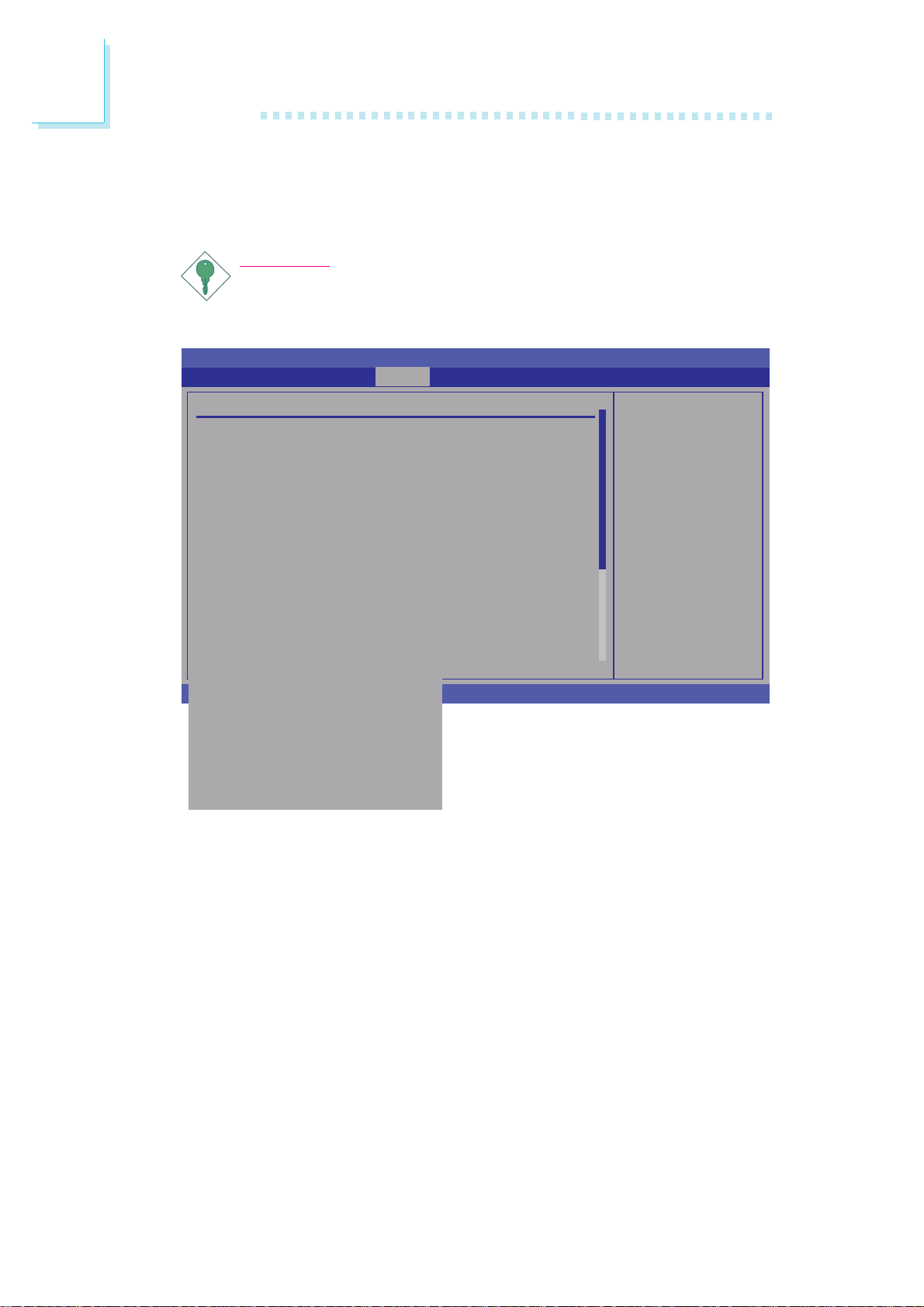
This section is used to configure settings for PCI/PnP devices.
Advanced PCI/PnP Settings
WARNING: Setting wrong values in below sections
Clear NVRAM [No]
Plug & Play O/S [No]
PCI Latency Timer [64]
Allocate IRQ to PCI VGA [Yes]
Palette Snooping [Disabled]
PCI IDE BusMaster [Enabled]
OffBoard PCI/ISA IDE Card [Auto]
IRQ3 [Available]
IRQ4 [Available]
IRQ5 [Available]
IRQ7 [Available]
IRQ9 [Available]
IRQ10 [Available]
IRQ11 [Available]
IRQ14 [Available]
IRQ15 [Available]
DMA Channel 0 [Available]
DMA Channel 1 [Available]
DMA Channel 3 [Available]
DMA Channel 5 [Available]
DMA Channel 6 [Available]
DMA Channel 7 [Available]
Reserved Memory Size [Disabled]
Important:
Setting incorrect field values may cause the system to malfunction.
BIOS SETUP UTILITY
PCIPnP
may cause system to malfunction.
v02.61 (C)Copyright 1985-2006, American Megatrends, Inc.
Boot SecurityMain Advanced
X
Clear NVRAM during
System Boot.
← → Select Screen
↑↓ Select Item
-
+
Change Option
F1 General Help
F10 Save and Exit
ESC Exit
X
ExitChipset
68
Clear NVRAM
This field allows clearing the NVRAM during system boot.
Plug & Play O/S
Yes Configures Plug and Play (PnP) devices that are not re-
quired to boot in a Plug and Play supported operating
system.
No The BIOS configures all the devices in the system.
Page 69

BIOS Setup
PCI Latency Timer
This feature is used to select the length of time each PCI device will
control the bus before another takes over. The larger the value, the
longer the PCI device can retain control of the bus.
Allocate IRQ to PCI VGA
Yes Assigns an IRQ to the PCI VGA card if the card re-
quested for one.
No Will not assign an IRQ to the PCI VGA card even when
the card requested for one.
Palette Snooping
When enabled, it informs PCI devices that an ISA graphics device is
installed in the system. This will allow the card to function normally.
3
PCI IDE BusMaster
When enabled, the BIOS uses PCI bus mastering when reading and
writing to IDE drives.
OffBoard PCI/ISA IDE Card
Some PCI IDE cards may need this field set to the PCI slot number
that is holding the card. Selecting Auto will work for most PCI IDE
cards.
IRQ3 to IRQ15
Available The specified IRQ is available for PCI/PnP devices.
Reserved The specified IRQ is reserved for Legacy ISA devices.
DMA Channel 0 to DMA Channel 7
Available The specified DMA is available for PCI/PnP devices.
Reserved The specified DMA is reserved for Legacy ISA de-
vices.
69
Page 70
3
BIOS Setup
Reserved Memory Size
Selects the size of memory block reserved for legacy ISA devices.
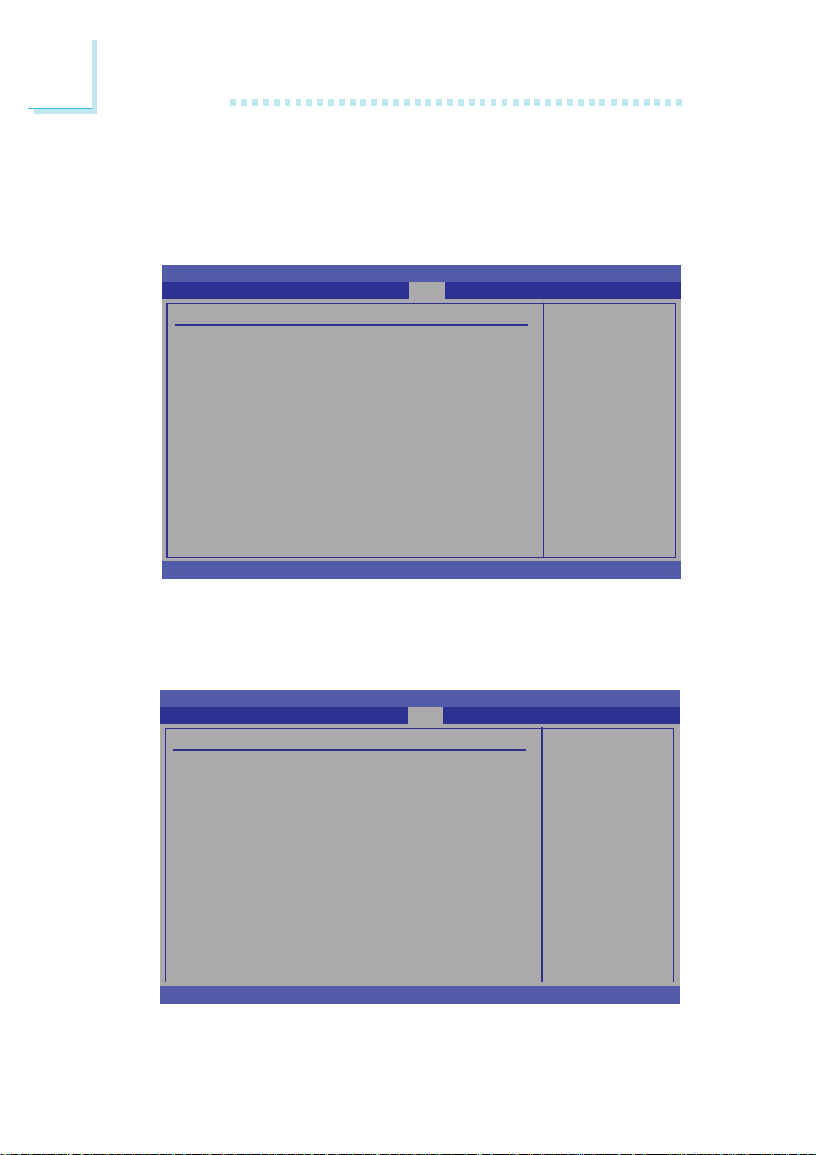
Boot
BIOS SETUP UTILITY
Boot
SecurityMain Advanced PCIPnP
ExitChipset
Boot Settings
X
Boot Settings Configuration
X
Boot Device Priority
v02.61 (C)Copyright 1985-2006, American Megatrends, Inc.
Boot Settings Configuration
This section is used to configure settings during system boot.
Configure settings
during system boot.
← → Select Screen
↑↓ Select Item
Enter Go to Sub Screen
F1 General Help
F10 Save and Exit
ESC Exit
BIOS SETUP UTILITY
Boot
70
Boot Settings Configuration
Quick Boot [Enabled]
Full Screen Logo Display [Disabled]
Bootup Num-Lock [On]
Boot To OS/2 [No]
Wait for ‘F1’ If Error [Enabled]
Hit ‘DEL’ Message Display [Enabled]
v02.61 (C)Copyright 1985-2006, American Megatrends, Inc.
Allows BIOS to skip
certain tests while
booting. This will
decrease the time
needed to boot the
system.
← → Select Screen
↑↓ Select Item
-
+
Change Option
F1 General Help
F10 Save and Exit
ESC Exit
Page 71

BIOS Setup
Quick Boot
When Enabled, the BIOS will shorten or skip some check items
during POST. This will decrease the time needed to boot the system.
Full Screen Logo Display
This field is applicable only if you want a particular logo to appear
during system boot-up.
Enabled The logo will appear in full screen during system boot-
up.
Disabled The logo will not appear during system boot-up.
Bootup Num-Lock
This allows you to determine the default state of the numeric
keypad. By default, the system boots up with NumLock on wherein
the function of the numeric keypad is the number keys. When set to
Off, the function of the numeric keypad is the arrow keys.
3
Boot To OS/2
The options are Yes and No.
Wait for ‘F1’ If Error
When enabled, the system will wait for the <F1> key to be pressed
when an error occurs.
Hit ‘DEL’ Message Display
When enabled, the system displays the “Press DEL to run Setup”
message during POST.
71
Page 72

3
BIOS Setup
Boot Device Priority
This section is used to select the boot priority sequence of the devices.
BIOS SETUP UTILITY
Boot
Boot Device Priority
1st Boot Device [USB:USB Hotplug FDD]
2nd Boot Device [CD/DVD:3M-_NEC DV-]
3rd Boot Device [SATA:PW-WDC WD1200]
v02.61 (C)Copyright 1985-2006, American Megatrends, Inc.
Specifies the boot
sequence from the
available devices.
A device enclosed in
parenthesis has been
disabled in the
corresponding type
menu.
← → Select Screen
↑↓ Select Item
-
+
Change Option
F1 General Help
F10 Save and Exit
ESC Exit
1st Boot Device to 3rd Boot Device
Select the drive to boot first, second and third in the “1st Boot
Device” “2nd Boot Device” and “3rd Boot Device” fields respectively.
The BIOS will boot the operating system according to the sequence
of the drive selected.
72
Page 73
Security
Security Settings
Supervisor Password : Not Installed
User Password : Not Installed
Change Supervisor Password
Change User Password
Boot Sector Virus Protection [Disabled]
BIOS SETUP UTILITY
Main Advanced PCIPnP
Boot Security
BIOS Setup
3
ExitChipset
<Enter> to change
password.
<Enter> again to
disable password.
← → Select Screen
↑↓ Select Item
Enter Change
F1 General Help
F10 Save and Exit
ESC Exit
v02.61 (C)Copyright 1985-2006, American Megatrends, Inc.
Change Supervisor Password
This field is used to set or change the supervisor password.
To set a new password:
1. Select the Change Supervisor Password field then press <Enter>.
2. Type your password in the dialog box then press <Enter>. You
are limited to eight letters/numbers.
3. Press <Enter> to confirm the new password.
4. When the Password Installed dialog box appears, select OK.
To change the password, repeat the same steps above.
To clear the password, select Change Supervisor Password then
press <Enter>. The Password Uninstalled dialog box will appear.
If you forgot the password, you can clear the password by erasing
the CMOS RTC (Real Time Clock) RAM using the Clear CMOS
jumper. Refer to the Jumper Settings section in chapter 2 for more
information.
73
Page 74
3
BIOS Setup
After you have set the supervisor password, the User Access Level
field will appear.
Main Advanced PCIPnP
BIOS SETUP UTILITY
Boot Security
ExitChipset
Security Settings
Supervisor Password : Installed
User Password : Not Installed
Change Supervisor Password
User Access Level [Full Access]
Change User Password
Password Check [Setup]
Boot Sector Virus Protection [Disabled]
v02.61 (C)Copyright 1985-2006, American Megatrends, Inc.
Limited: only limited
fields to be changed.
No Access: prevent
user access Setup
Utility.
View Only: allow
access but the fields
can not be changed.
Full: allow change
except Supervisor
password.
← → Select Screen
↑↓ Select Item
-
+
Change Option
F1 General Help
F10 Save and Exit
ESC Exit
User Access Level
Selects the access level to the fields in the Setup utility.
Limited Allows you to change settings to some fields such as
Date and Time.
No Access Prevents access to the Setup utility.
View Only Allows you to view the settings but does not allow
you to change the settings.
Full Access Allows you to change settings to all the fields in the
utility.
74
Change User Password
This field is used to set or change the user password.
To set a new password:
1. Select the Change User Password field then press <Enter>.
2. Type your password in the dialog box then press <Enter>. You
are limited to eight letters/numbers.
3. Press <Enter> to confirm the new password.
4. When the Password Installed dialog box appears, select OK.
Page 75

BIOS Setup
To change the password, repeat the same steps above.
After you have set the user password, the Clear User Password and
Password Check fields will appear.
Clear User Password
To clear the password, select Clear User Password then press <Enter>. The Password Uninstalled dialog box will appear.
Password Check
Setup The BIOS checks for the user password whenever
accessing the Setup utility.
Always The BIOS checks for the user password when ac-
cessing the Setup utility and booting the system.
3
Boot Sector Virus Protection
Enables or disables the boot sector virus protection function.
75
Page 76
3
BIOS Setup
Chipset
This section is used to configure the system based on the specific
features of the chipset.
Important:
Setting incorrect field values may cause the system to malfunction.
BIOS SETUP UTILITY
PCIPnP
Boot SecurityMain Advanced
Chipset
Exit
Advanced Chipset Settings
WARNING: Setting wrong values in below sections
X
North Bridge Configuration
X
South Bridge Configuration
may cause system to malfunction.
v02.61 (C)Copyright 1985-2006, American Megatrends, Inc.
North Bridge Configuration
North Bridge Chipset Configuration
DRAM Frequency [Auto]
Configure DRAM Timing by SPD [Enabled]
Boots Graphic Adapter Priority [PCI/IGD]
Internal Graphics Mode Select [Enabled, 8MB]
X
Video Function Configuration
Configure North Bridge
features.
← → Select Screen
↑↓ Select Item
Enter Go to Sub Screen
F1 General Help
F10 Save and Exit
ESC Exit
BIOS SETUP UTILITY
Chipset
Options
Auto
533 MHz
667 MHz
76
← → Select Screen
↑↓ Select Item
+
F1 General Help
F10 Save and Exit
ESC Exit
v02.61 (C)Copyright 1985-2006, American Megatrends, Inc.
-
Change Option
Page 77
BIOS Setup
DRAM Frequency
Selects the operating frequency of the DRAM.
Configure DRAM Timing by SPD
The EEPROM on a DIMM has SPD (Serial Presence Detect) data
structure that stores information about the module such as the
memory type, memory size, memory speed, etc. When this field is
enabled, the system will run according to the information in the
EEPROM.
Boots Graphic Adapter Priority
Selects which graphics controller to use as the primary boot device.
Internal Graphics Mode Select
3
Selects the amount of system memory used by the internal graphics
device.
Video Function Configuration
BIOS SETUP UTILITY
Chipset
Video Function Configuration
DVMT Mode Select [DVMT Mode]
DVMT/FIXED Memory [256MB]
Boot Display Device [VBIOS-Default]
Local Flat Panel Scaling [Auto]
Flat Panel Type [03. 1024x768, 18bit]
Spread Spectrum Clock [Disabl ed]
Fixed Mode
DVMT Mode
Options
← → Select Screen
↑↓ Select Item
-
+
Change Option
F1 General Help
F10 Save and Exit
ESC Exit
v02.61 (C)Copyright 1985-2006, American Megatrends, Inc.
77
Page 78

3
BIOS Setup
DVMT Mode Select
DVMT Mode Memory that is dynamically allocated based on
memory requests made by an application and
are released back to the system once the requesting application has been terminated.
Fixed Mode Non-contiguous pagelocked memory allocated
during driver initialization to provide a static
amount of memory.
DVMT/FIXED Memory
Selects the graphics memory size used by the DVMT/Fixed mode.
Boot Display Device
Selects the type of display to use when the system boots.
Local Flat Panel Scaling
Selects the local flat panel’s scaling method.
Flat Panel Type
Selects the type of flat panel connected to the system.
Spread Spectrum Clock
The options are Enabled and Disabled.
78
Page 79
South Bridge Configuration
BIOS Setup
3
BIOS SETUP UTILITY
Chipset
South Bridge Chipset Configuration
USB Functions [6 USB P orts ]
USB 2.0 Controller [Enabled]
HDA Controller [Enabled]
OnBoard GLAN 1 [Enabled]
OnBoard GLAN 2 [Enabled]
v02.61 (C)Copyright 1985-2006, American Megatrends, Inc.
Disabled
Enabled
Options
← → Select Screen
↑↓ Select Item
-
+
Change Option
F1 General Help
F10 Save and Exit
ESC Exit
USB Functions
This field is used to select the number of USB ports you want
enabled.
USB 2.0 Controller
Enables or disables the USB 2.0 controller.
HDA Controller
Enables or disables the High Definition audio controller.
OnBoard GLAN 1
Enables or disables the onboard Gigabit LAN 1.
OnBoard GLAN 2
Enables or disables the onboard Gigabit LAN 2.
79
Page 80
3
BIOS Setup
Exit
BIOS SETUP UTILITY
Boot SecurityMain Advanced PCIPnP
Chipset
Exit
Exit Options
Exit & Save Changes
Exit & Discard Changes
Discard Changes
Load Optimal Defaults
Load Failsafe Defaults
v02.61 (C)Copyright 1985-2006, American Megatrends, Inc.
Exit system setup
after saving the
changes.
F10 key can be used
for this operation.
← → Select Screen
↑↓ Select Item
Enter Go to Sub Screen
F1 General Help
F10 Save and Exit
ESC Exit
Exit & Save Changes
To save the changes and exit the Setup utility, select this field then
press <Enter>. A dialog box will appear. Confirm by selecting Yes.
You can also press <F10> to save and exit Setup.
Exit & Discard Changes
To exit the Setup utility without saving the changes, select this field
then press <Enter>. You may be prompted to confirm again before
exiting.
You can also press <ESC> to exit without saving the changes.
Discard Changes
To discard the changes, select this field then press <Enter>. A dialog
box will appear. Confirm by selecting Yes to discard all changes made
and restore the previously saved settings.
You can also press <F7> to discard the changes.
80
Page 81

BIOS Setup
Load Optimal Defaults
Loads the optimal default values from the BIOS ROM.
You can also press <F9> to load optimal default values.
Load Failsafe Defaults
Loads the fail-safe default values from the BIOS ROM.
You can also press <F8> to load the fail-safe default values.
3
81
Page 82

3
BIOS Setup
Updating the BIOS
To update the BIOS, you will need the new BIOS file and a flash
utility, AFUDOS.EXE. Please contact technical support or your sales
representative for the files.
To execute the utility, type:
A:> AFUDOS BIOS_File_Name /b /n /c /p
then press <Enter>.
C:\>AFUDOS.EXE SR100N78.29A /P /B /N /C
+--------------------------------------------------------------------------------------------------------+
|
|
+--------------------------------------------------------------------------------------------------------+
- Bootblock checksum .................
- Module checksums ...................
- Erasing flash .............................
- Writing flash .............................
- Verifying flash ..........................
- Erasing NVRAM ......................
- Writing NVRAM ......................
- Verifying NVRAM ...................
- Erasing Bootblock .....................
- Writing Bootblock .....................
- Verifying Bootblock ..................
- CMOS checksum destroyed
- Program ended normally
C:\>_
Copyright (C) 2007 American Megatrends Inc. All Rights Reserved.
AMI Firmware Update Utility Ver. 4.14
ok
ok
done
done
done
done
done
done
done
done
done
|
|
82
Page 83
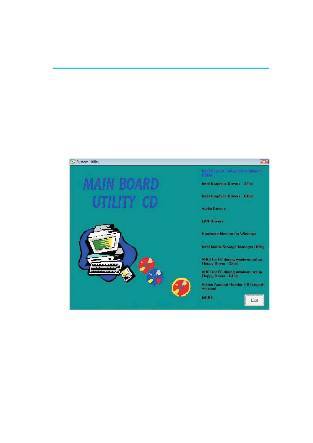
Chapter 4 - Supported Software
Drivers for Windows Vista System
The CD that came with the system board contains drivers, utilities
and software applications required to enhance the performance of
the system board. Insert the CD into a CD-ROM drive. The autorun
screen (Mainboard Utility CD) will appear. If after inserting the CD,
"Autorun" did not automatically start, please go directly to the root
directory of the CD and double-click "Setup".
Supported Software
4
83
Page 84
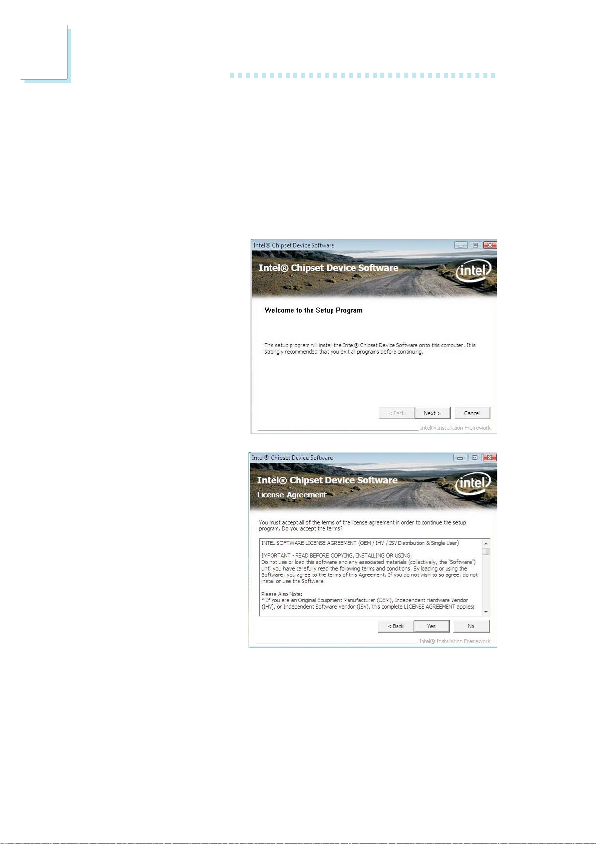
4
Supported Software
Intel Chipset Software Installation Utility
The Intel Chipset Software Installation Utility is used for updating
Windows® INF files so that the Intel chipset can be recognized and
configured properly in the system.
To install the utility, click “Intel Chipset Software Installation Utility” on the
main menu.
1. Setup is now ready to
install the utility. Click
Next.
2. Read the license
agreement then click Yes.
84
Page 85
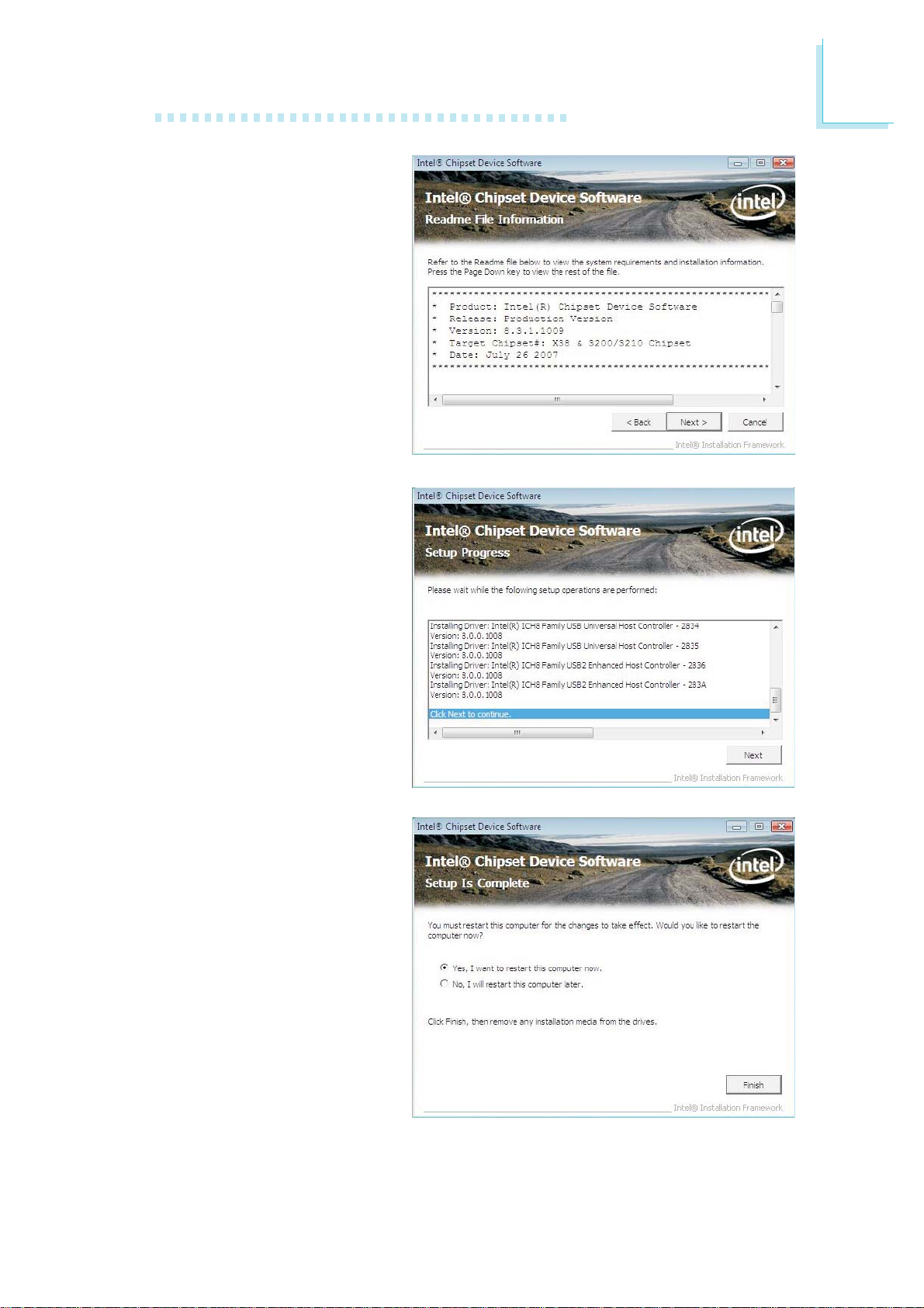
3. Go through the readme
document for system
requirements and
installation tips then click
Next.
4. Setup is now installing
the driver. Click Next to
continue.
Supported Software
4
5. After completing installation, click Finish to exit
setup.
85
Page 86
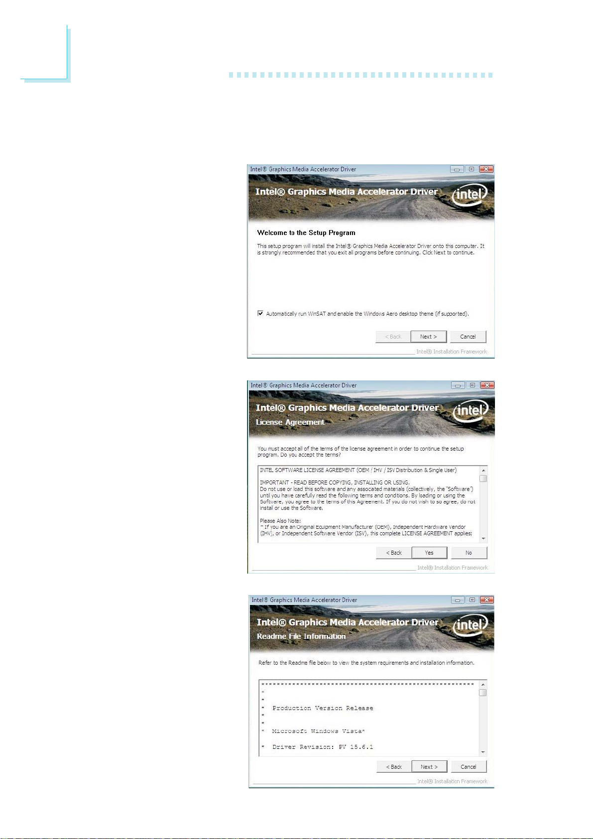
4
Supported Software
Intel Graphics Drivers
To install the driver, click “Intel Graphics Drivers” on the main menu.
1. Setup is now ready to
install the graphics driver.
Click Next.
2. Read the license
agreement then click Yes.
3. Go through the readme
document for system
requirements and
installation tips then click
Next.
86
Page 87
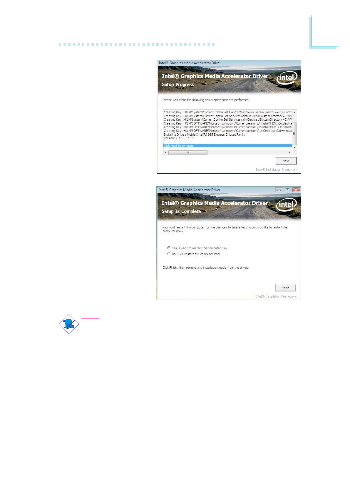
4. Setup is now installing
the driver. Click Next to
continue.
5. Click “Yes, I want to
restart this computer
now” then click Finish.
Supported Software
4
Restarting the system will
allow the new software
installation to take effect.
Note:
After installing the graphics driver and the system rebooted, the
screen will turn black for 1 to 2 minutes (while WinSAT is running)
before the Windows Vista desktop appears. This will happen the first
time you reboot after installing the graphics driver as this is the time
when the system will automatically detect and mount the graphics
driver.
87
Page 88
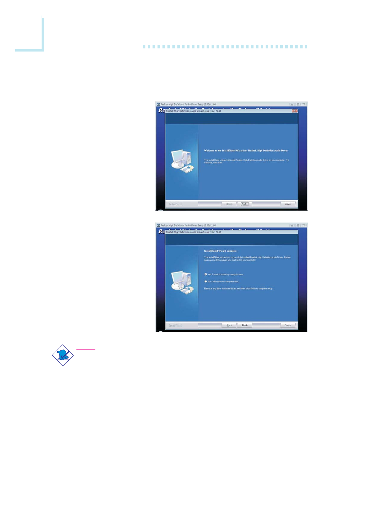
4
Supported Software
Audio Drivers
To install the driver, click “Audio Drivers” on the main menu.
1. Click Next to start the
installation.
2. Follow the remainder of
the steps on the screen;
clicking “Next” each time
you finish a step.
3. Click “Yes, I want to
restart my computer
now” then click Finish.
Restarting the system will
allow the new software
installation to take effect.
Note:
After installing the audio driver under Windows Vista, you will see an
“X” mark on the audio icon. This is normal. This mark will disappear
when you connect an external speaker to the speaker-out jack.
88
Page 89
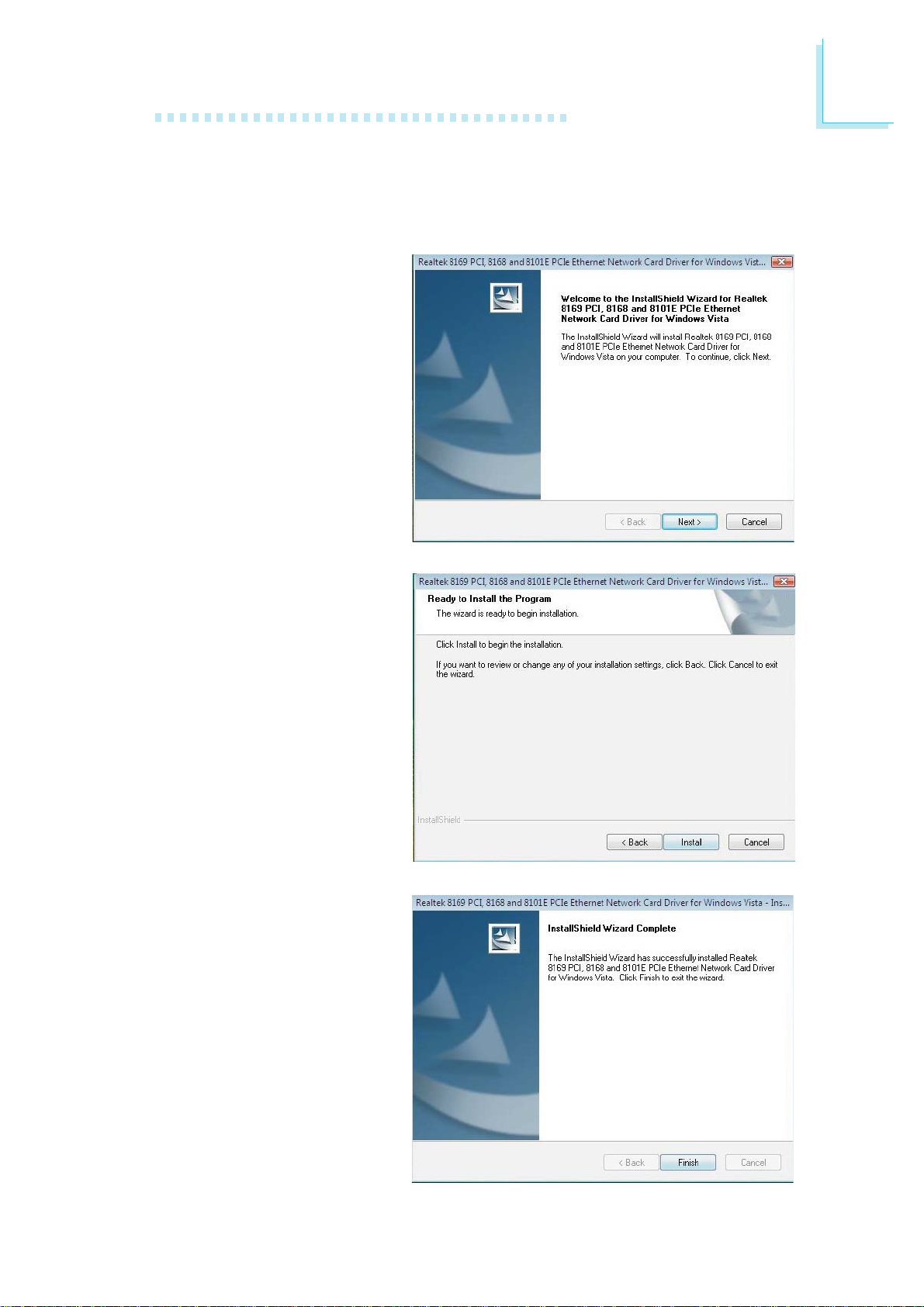
Supported Software
LAN Drivers
To install the driver, click “LAN Drivers” on the main menu.
1. Setup is now ready to
install the driver. Click
Next.
4
2. Click Install to begin
installation.
3. After completing installation, click Finish to exit
setup.
89
Page 90
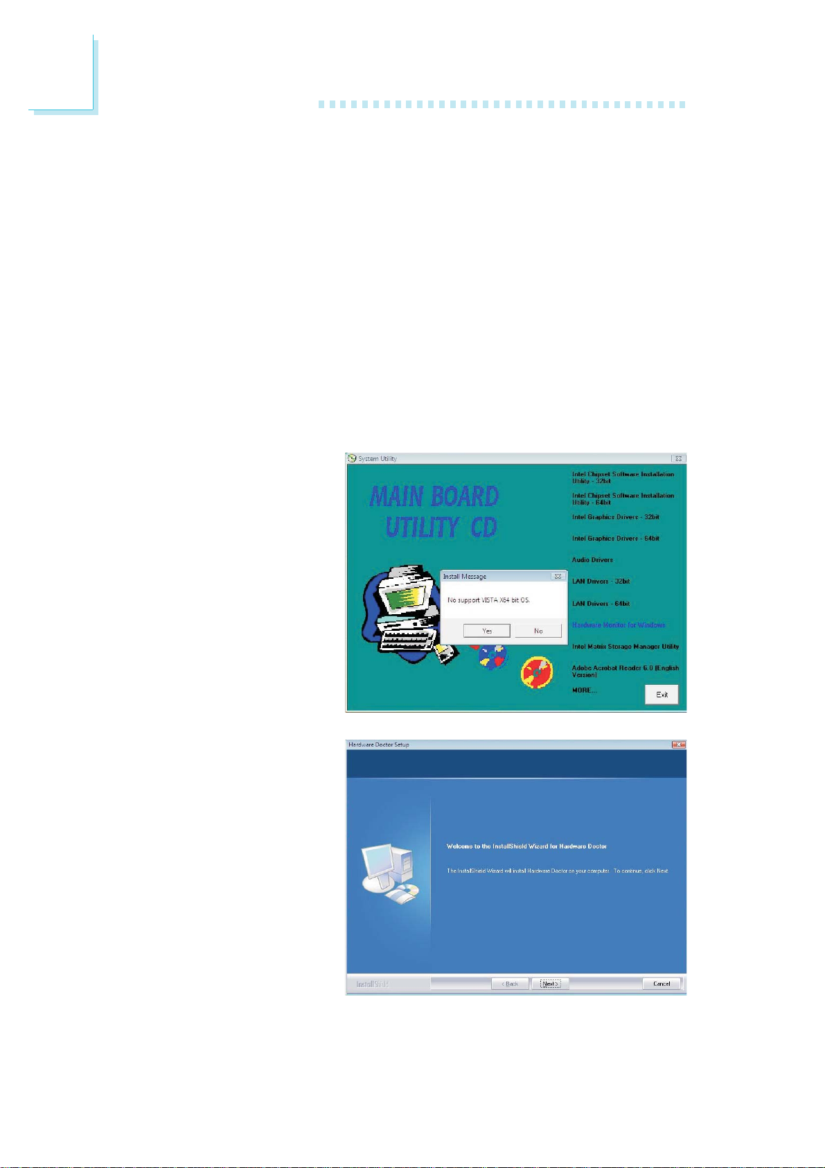
4
Supported Software
Hardware Monitor for Windows
The Hardware Monitor for Windows utility is capable of monitoring the
system’s temperature, fan speed, voltage, etc. and allows you to manually
set a range (Highest and Lowest Limit) to the items being monitored. If
the settings/values are over or under the set range, a warning message will
pop-up. The utility can also be configured so that a beeping alarm will
sound whenever an error occurs. We recommend that you use the “Default Setting” which is the ideal setting that would keep the system in good
working condition.
To install the utility, click “Hardware Monitor for Windows” on the main
menu.
1. Click Yes to continue.
90
2. Setup is now ready to
install the utility. Click
Next.
Page 91
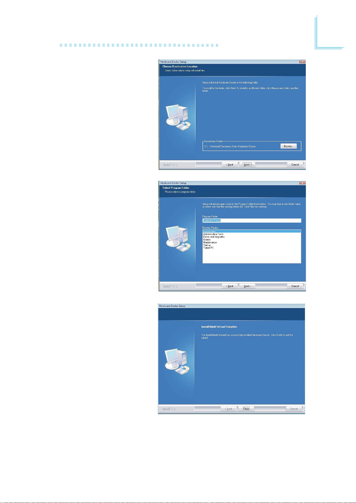
3. Click Next to install or
click Browse to select
another folder.
4. Click Next to add the
program icon to the
Program Folder.
Supported Software
4
5. After completing installation, click Finish to exit
setup.
91
Page 92
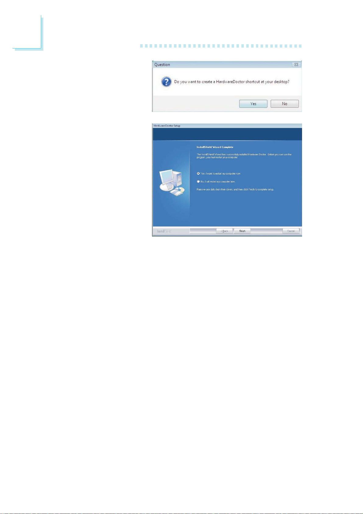
4
Supported Software
6. Click Yes if you want to
create a Hardware
Doctor shortcut at your
desktop.
7. Click “Yes, I want to
restart my computer
now” then click Finish.
Restarting the system will
allow the utility to take
effect.
92
Page 93
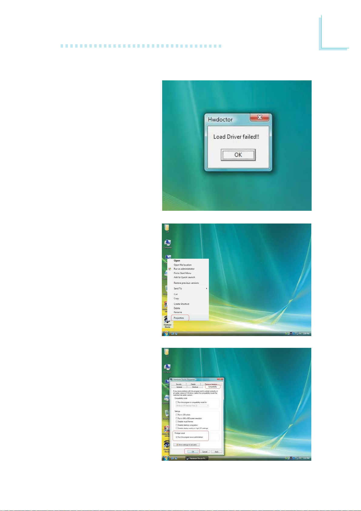
Supported Software
Using the Hardware Monitor for Windows Utility
1. When you try to run the
utility, which is usually
done by double-clicking
the Hardware Doctor
shortcut, an error
message will appear.
4
2. To solve this problem,
right-click the Hardware
Doctor shortcut. then
select Properties.
3. Select the Compatibility
tab, click “Run this program as an administrator” then click OK.
93
Page 94
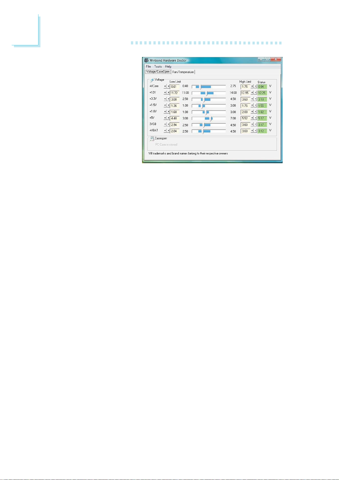
4
Supported Software
4. You can now access the
utility.
94
Page 95
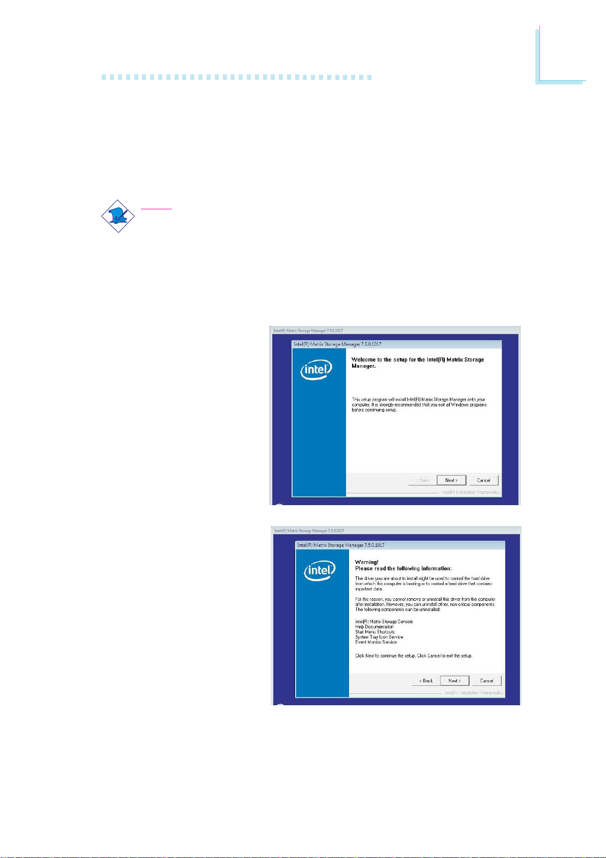
Supported Software
Intel Matrix Storage Manager Utility
Intel Matrix Storage Manager is a utility that allows you to monitor the
current status of the SATA drives. It enables enhanced performance and
power management for the storage subsystem.
Note:
This utility is supported only when the Configure SATA As field is set
to AHCI. (The Configure SATA As field is in the Main menu of the
BIOS utility.)
To install the utility, click “Intel Matrix Storage Manager Utility” on the main
menu.
1. Setup is now ready to
install the utility. Click
Next.
4
2. Read the Warning information carefully then click
Next to begin installation.
95
Page 96
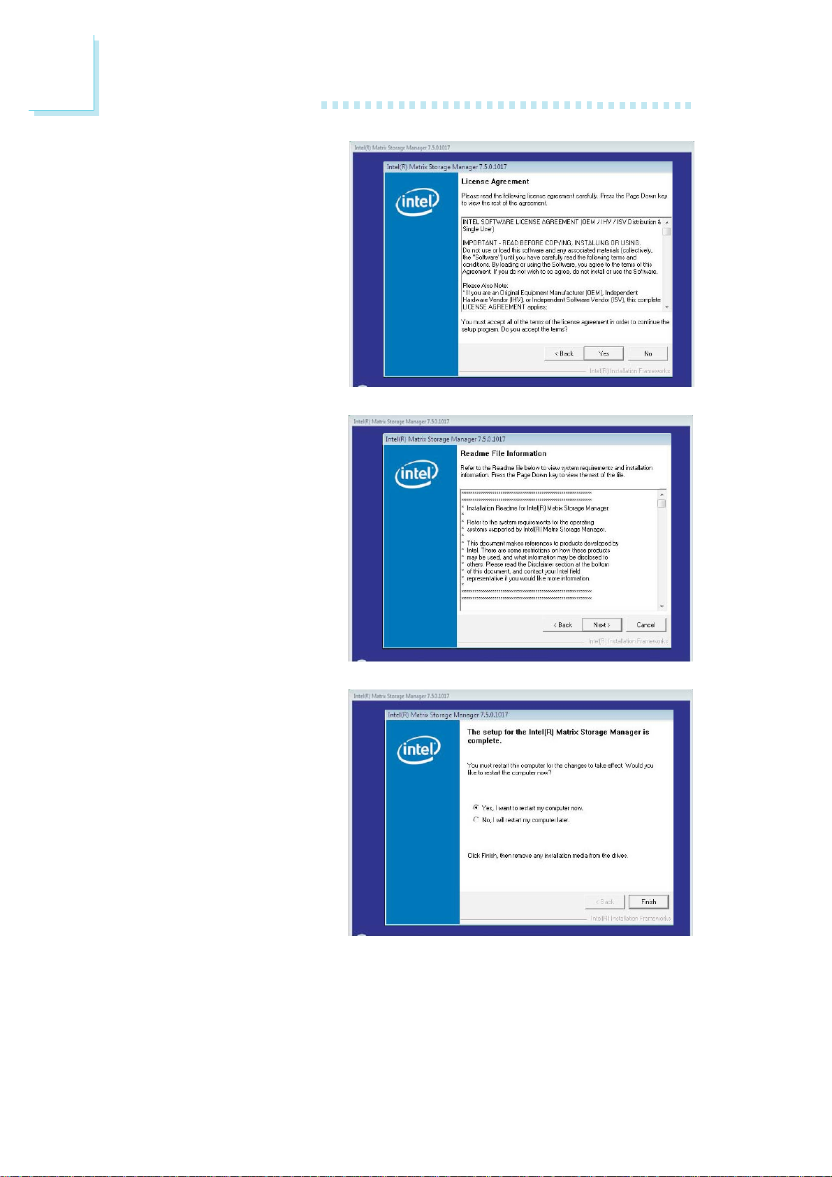
4
Supported Software
3. Read the license
agreement then click Yes.
4. Go through the readme
document for system
requirements and
installation tips then click
Next.
5. Click “Yes, I want to
restart my computer
now” then click Finish.
Restarting the system will
allow the new software
installation to take effect.
96
Page 97
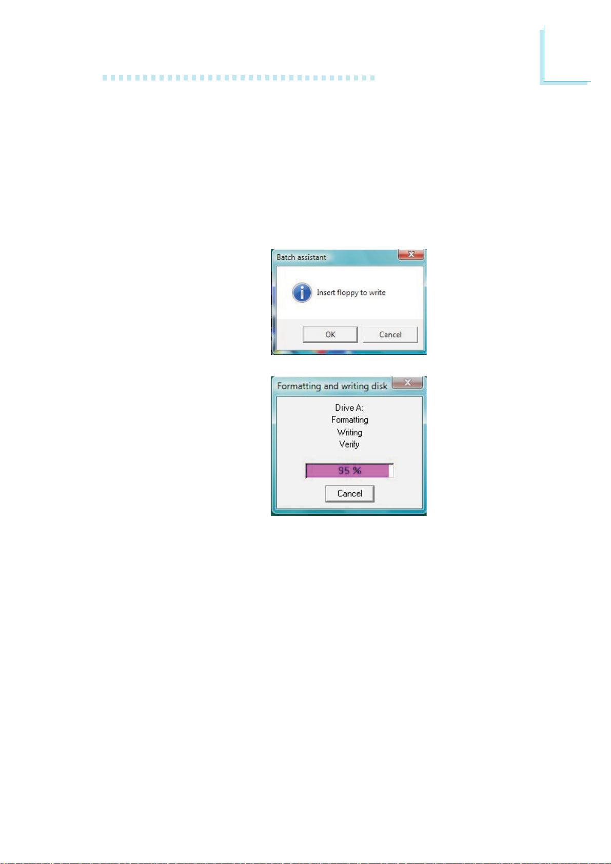
Supported Software
AHCI for F6 During Windows Setup Floppy Driver
This is used to create a floppy driver diskette needed when you install
Windows® XP using the F6 installation method. This will allow you to install
the operating system onto a hard drive when in AHCI mode.
Click “AHCI for F6 During Windows Setup Floppy Driver” on the main
menu.
1. Insert a blank floppy
diskette then click OK.
4
2. The system is currently
formatting and writing
the necessary driver files
into the diskette.
97
Page 98
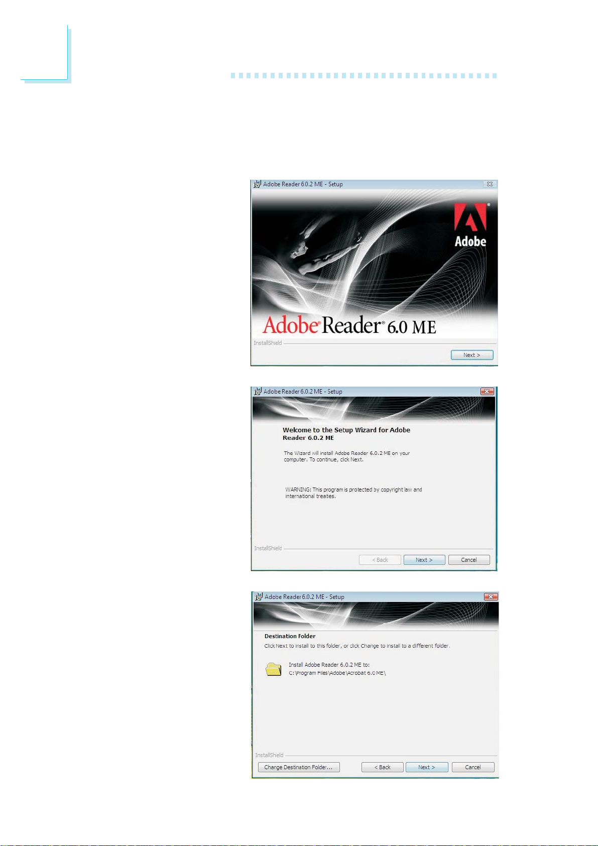
4
Supported Software
Adobe Acrobat Reader 6.0 (English Version)
To install, click “Adobe Acrobat Reader 6.0 (English Version)” on the main
menu.
1. Click Next to continue.
2. Setup is now ready to
install. Click Next.
3. Click Next to install or
click Change Destination
Folder to select another
folder.
98
Page 99
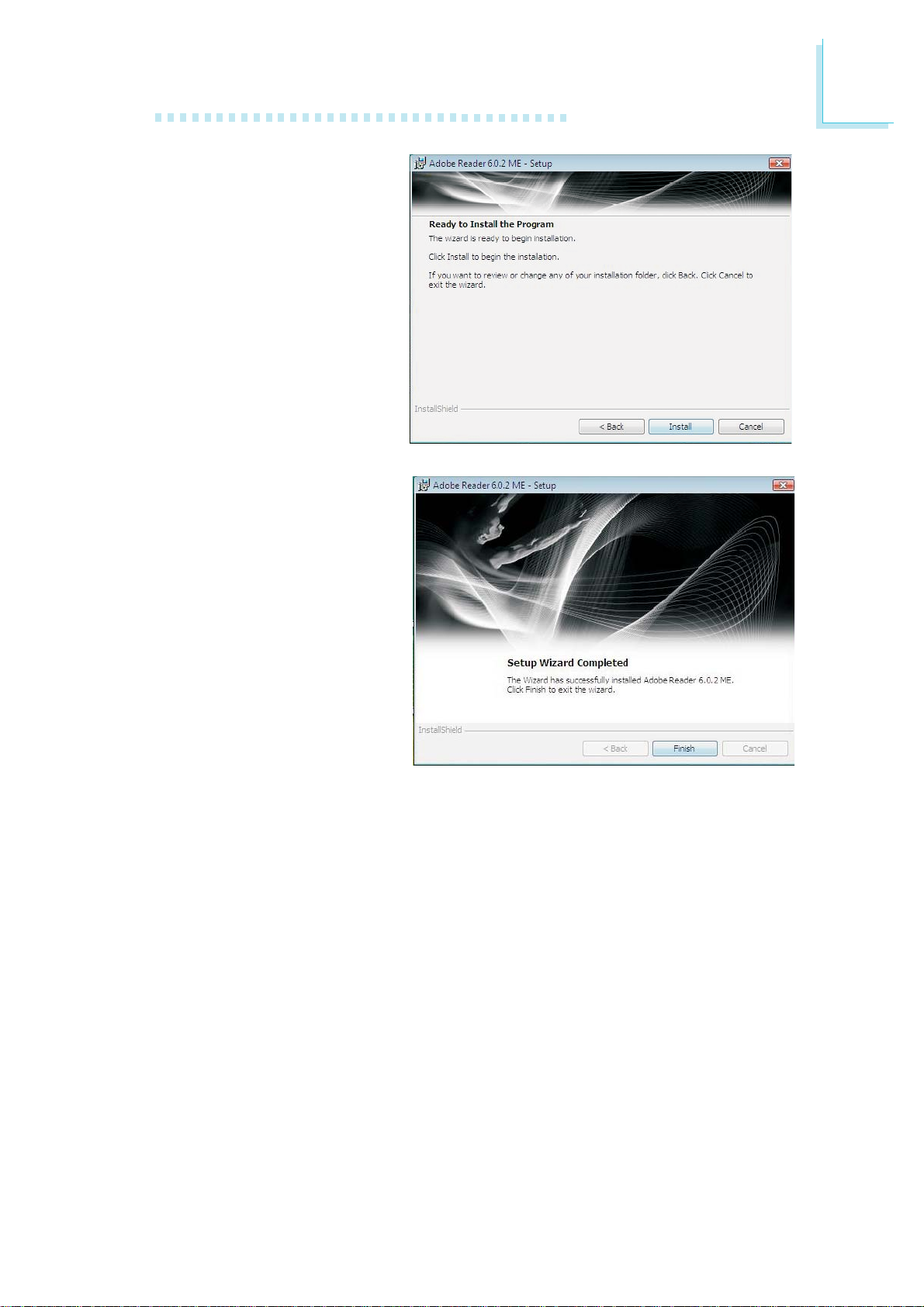
4. Click Install to begin
installation.
5. Click Finish to exit
installaion.
Supported Software
4
99
Page 100
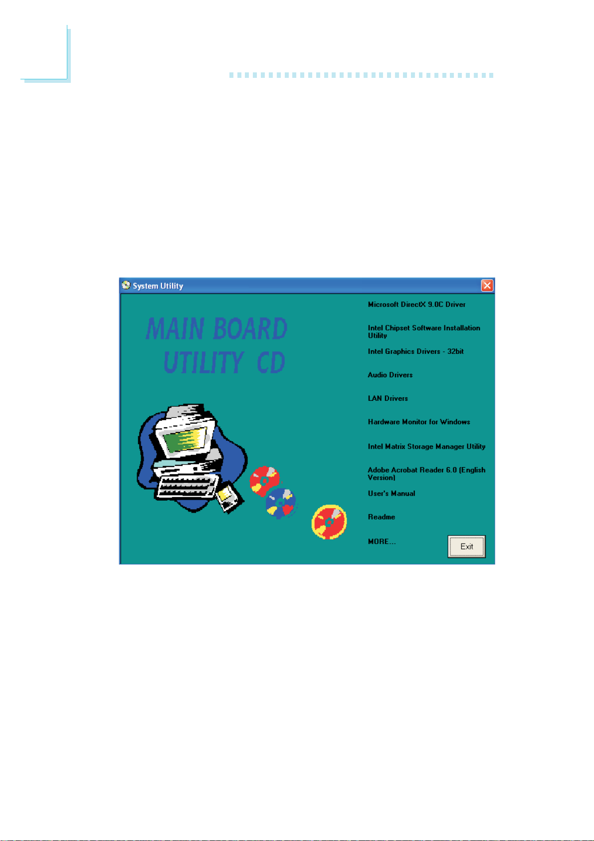
4
Supported Software
Drivers for Windows XP System
The CD that came with the system board contains drivers, utilities
and software applications required to enhance the performance of
the system board.
Insert the CD into a CD-ROM drive. The autorun screen (Main
Board Utility CD) will appear. If after inserting the CD, "Autorun" did
not automatically start, please go directly to the root directory of the
CD and double-click "Setup".
100
 Loading...