

Page 1

System Board
User’s Manual
935-N65UT1-000G
01000713
Page 2

Copyright
This publication contains information that is protected by copyright.
No part of it may be reproduced in any form or by any means or
used to make any transformation/adaptation without the prior
written permission from the copyright holders.
This publication is provided for informational purposes only. The
manufacturer makes no representations or warranties with respect to
the contents or use of this manual and specifically disclaims any
express or implied warranties of merchantability or fitness for any
particular purpose. The user will assume the entire risk of the use or
the results of the use of this document. Further, the manufacturer
reserves the right to revise this publication and make changes to its
contents at any time, without obligation to notify any person or
entity of such revisions or changes.
© 2007. All Rights Reserved.
Trademarks
Product names or trademarks appearing in this manual are for identification purpose only and are the properties of the respective owners.
Page 3

FCC and DOC Statement on Class B
This equipment has been tested and found to comply with the limits
for a Class B digital device, pursuant to Part 15 of the FCC rules.
These limits are designed to provide reasonable protection against
harmful interference when the equipment is operated in a residential
installation. This equipment generates, uses and can radiate radio
frequency energy and, if not installed and used in accordance with
the instruction manual, may cause harmful interference to radio
communications. However, there is no guarantee that interference
will not occur in a particular installation. If this equipment does cause
harmful interference to radio or television reception, which can be
determined by turning the equipment off and on, the user is
encouraged to try to correct the interference by one or more of the
following measures:
• Reorient or relocate the receiving antenna.
• Increase the separation between the equipment and the receiver.
• Connect the equipment into an outlet on a circuit different from
that to which the receiver is connected.
• Consult the dealer or an experienced radio TV technician for
help.
Notice:
1. The changes or modifications not expressly approved by the
party responsible for compliance could void the user's authority
to operate the equipment.
2. Shielded interface cables must be used in order to comply with
the emission limits.
Page 4

Table of Contents
About this Manual................................................................................
Warranty.................................................................................................
Registering the Product.......................................................................
Static Electricity Precaution................................................................
Safety Measures.....................................................................................
About the Package...............................................................................
Before Using the System Board.........................................................
Chapter 1 - Introduction....................................................................
Specifications...................................................................................................................................
Features..............................................................................................................................................
Français................................................................................................................................................
Deutsch...............................................................................................................................................
Español................................................................................................................................................
Русский язык.........................................................................................................................
Japanese.............................................................................................................................................
Chapter 2 - Hardware Installation....................................................
System Board Layout ..........................................................................................................
System Memory..........................................................................................................................
CPU.......................................................................................................................................................
Jumper Settings............................................................................................................................
Rear Panel I/O Ports.............................................................................................................
Internal I/O Connectors.....................................................................................................
Chapter 3 - BIOS Setup......................................................................
Award BIOS Setup Utility.................................................................................................
RAID BIOS.....................................................................................................................................
Updating the BIOS..................................................................................................................
Chapter 4 - Supported Softwares.....................................................
Chapter 5 - RAID.................................................................................
Appendix A - Enabling Hyper-Threading Technology...................
Appendix B - System Error Message...............................................
Appendix C - Troubleshooting..........................................................
5
5
6
8
8
9
9
10
10
12
16
18
20
22
24
26
26
27
31
38
44
55
71
71
121
122
124
143
147
150
152
Page 5

About this Manual
An electronic file of this manual is included in the CD. To view the
user’s manual, insert the CD into a CD-ROM drive. The autorun
screen will appear. Click the “TOOLS” icon then click “Manual” on the
main menu.
Warranty
1. Warranty does not cover damages or failures that arised from
misuse of the product, inability to use the product, unauthorized
replacement or alteration of components and product
specifications.
2. The warranty is void if the product has been subjected to
physical abuse, improper installation, modification, accidents or
unauthorized repair of the product.
3. Unless otherwise instructed in this user’s manual, the user may
not, under any circumstances, attempt to perform service,
adjustments or repairs on the product, whether in or out of
warranty. It must be returned to the purchase point, factory or
authorized service agency for all such work.
4. We will not be liable for any indirect, special, incidental or
consequencial damages to the product that has been modified
or altered.
Page 6
Introduction
1
6
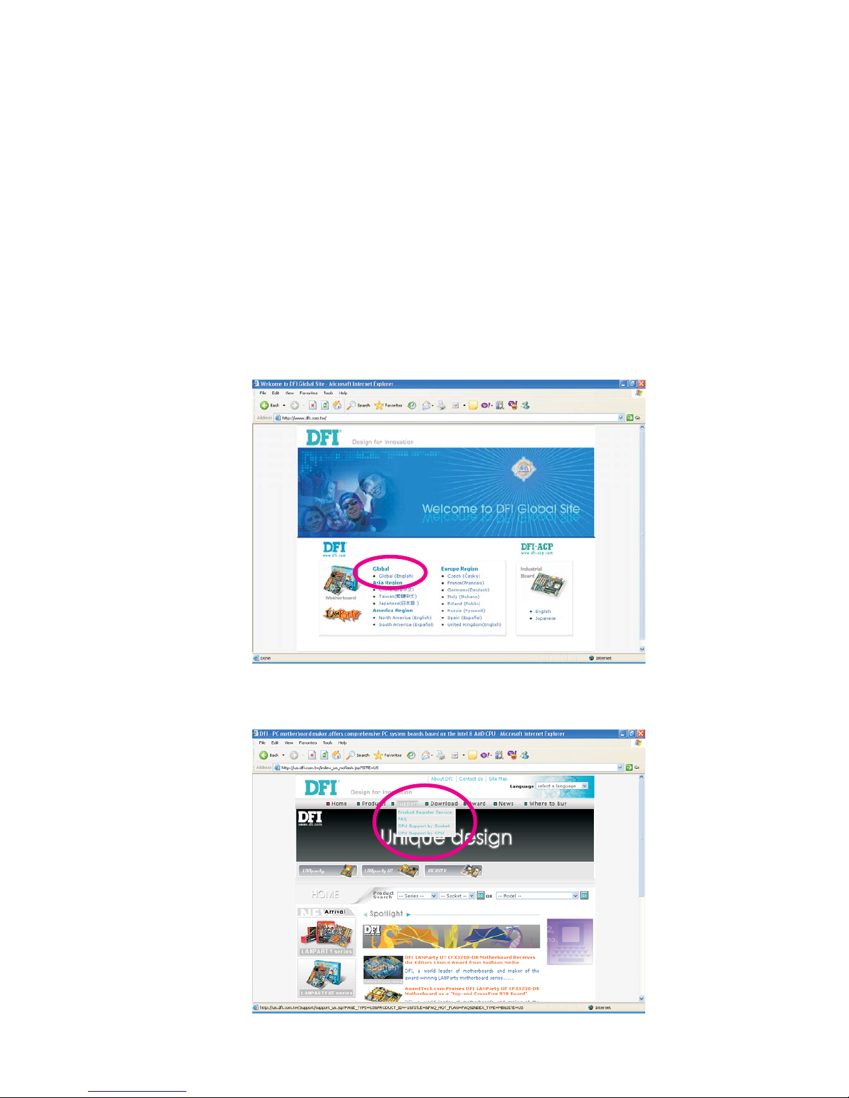
Registering the Product
We encourage you to register your DFI product online. DFI’s product
registration service entitles you to notifications about product
updates, special discounts and/or promotional offers; and puts your
licensing information on file so that we may efficiently assist you if in
any case needed. Please follow the steps below to access the
product registration page.
1. Run Internet Explorer then type www.dfi.com.tw in the Address bar.
On DFI’s homepage, click Global or the language of your choice.
2. Click the Support menu then select Product Register Service.
Page 7
1
Introduction
7
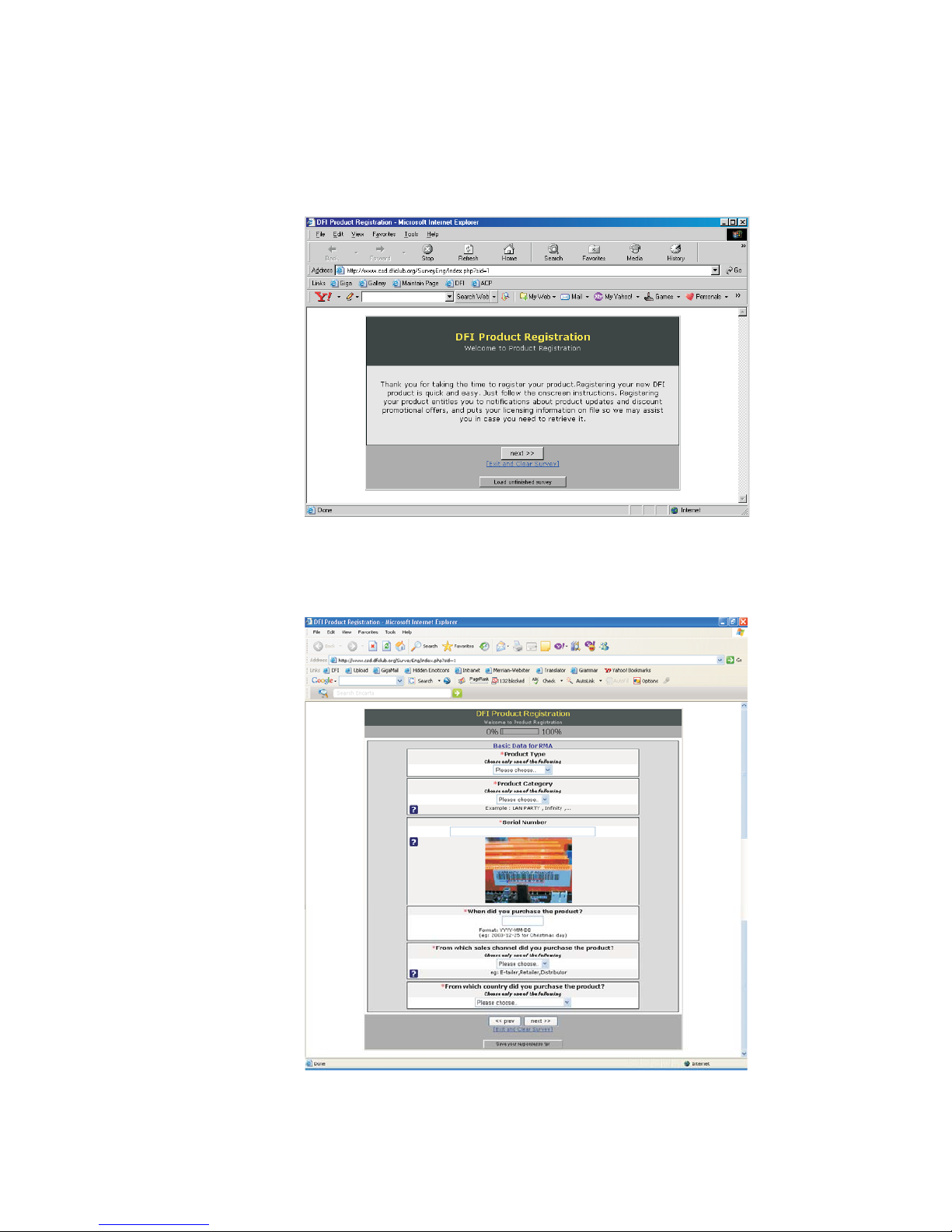
3. The DFI Product Registration page will appear. Click Next to
continue.
4. Select or fill in the necessary information to complete the
registration.
5. Thank you for registering your DFI product.
Page 8

Introduction
1
8
Static Electricity Precautions
It is quite easy to inadvertently damage your PC, system board,
components or devices even before installing them in your system
unit. Static electrical discharge can damage computer components
without causing any signs of physical damage. You must take extra
care in handling them to ensure against electrostatic build-up.
1. To prevent electrostatic build-up, leave the system board in its
anti-static bag until you are ready to install it.
2. Wear an antistatic wrist strap.
3. Do all preparation work on a static-free surface.
4. Hold the device only by its edges. Be careful not to touch any of
the components, contacts or connections.
5. Avoid touching the pins or contacts on all modules and
connectors. Hold modules or connectors by their ends.
Important:
Electrostatic discharge (ESD) can damage your processor, disk
drive and other components. Perform the upgrade instruction
procedures described at an ESD workstation only. If such a
station is not available, you can provide some ESD protection
by wearing an antistatic wrist strap and attaching it to a metal
part of the system chassis. If a wrist strap is unavailable,
establish and maintain contact with the system chassis
throughout any procedures requiring ESD protection.
Safety Measures
To avoid damage to the system:
• Use the correct AC input voltage range
..
..
.
To reduce the risk of electric shock:
• Unplug the power cord before removing the system chassis
cover for installation or servicing. After installation or servicing,
cover the system chassis before plugging the power cord.
Battery:
• Danger of explosion if battery incorrectly replaced.
• Replace only with the same or equivalent type recommend
by
the manufacturer.
• Dispose of used batteries according to the battery
manufacturer’s
instructions.
Page 9

1
Introduction
9
About the Package
The system board package contains the following items. If any of
these items are missing or damaged, please contact your dealer or
sales representative for assistance.
; One system board
; One IDE cable
; One floppy cable
; Two Serial ATA data cables
; One Serial ATA power cable
; One I/O shield
; One “Mainboard Utility” CD
; One RAID floppy diskette
; One user’s manual
The system board and accessories in the package may not come
similar to the information listed above. This may differ in accordance
to the sales region or models in which it was sold. For more
information about the standard package in your region, please
contact your dealer or sales representative.
Before Using the System Board
Before using the system board, prepare basic system components.
If you are installing the system board in a new system, you will need
at least the following internal components.
• A CPU
• Memory module
• Storage devices such as hard disk drive, CD-ROM, etc.
You will also need external system peripherals you intend to use
which will normally include at least a keyboard, a mouse and a video
display monitor.
Page 10

Introduction
1
10
Chapter 1 - Introduction
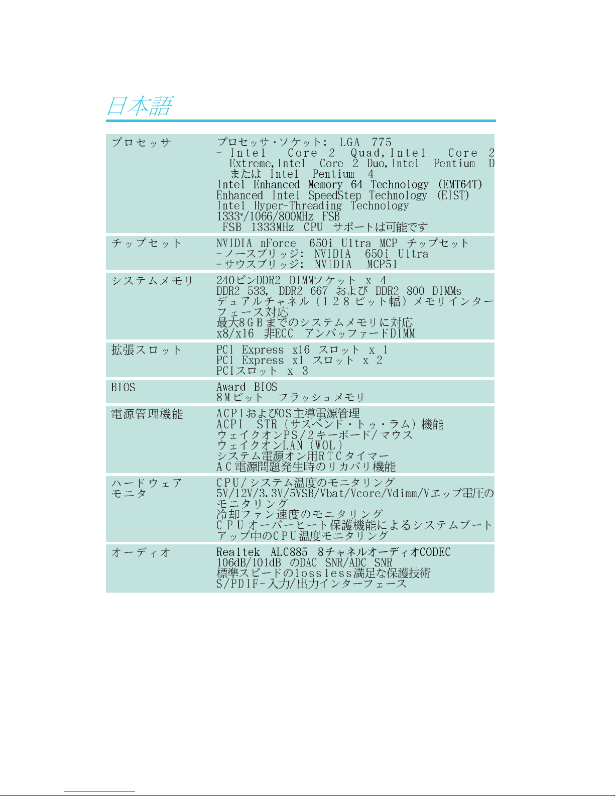
Specifications
Processor
Chipset
System Memory
Expansion Slots
BIOS
Power Management
Hardware Monitor
• LGA 775 socket for:
- Intel
®
CoreTM2 Quad, Intel® CoreTM2 Extreme, Intel® CoreTM2
Duo, Intel
®
Pentium® D or Intel® Pentium® 4
• Intel Enhanced Memory 64 Technology (EMT64T)
• Enhanced Intel SpeedStep Technology (EIST)
• Intel Hyper-Threading Technology
• 1333*/1066/800MHz FSB
*Available on CPUs that support 1333MHz FSB
• NVIDIA nForce
®
650i Ultra MCP
- Northbridge: NVIDIA® 650i Ultra
- Southbridge: NVIDIA® MCP51
• Four 240-pin DDR2 DIMM sockets
• DDR2 533, DDR2 667 and DDR2 800 DIMMs
• Dual channel (128-bit wide) memory interface
• Up to 8GB system memory
• Non-ECC x8 and x16 unbuffered DIMMs
• 1 PCI Express x16 slot
• 2 PCI Express x1 slots
• 3 PCI slots
• Award BIOS
• 8Mbit flash memory
• ACPI and OS Directed Power Management
• ACPI STR (Suspend to RAM) function
• Wake-On-PS/2 Keyboard/Mouse
• Wake-On-LAN
• RTC timer to power-on the system
• AC power failure recovery
• Monitors CPU/system/chipset temperature
• Monitors 12V/5V/3.3V/Vcore/Vbat/5Vsb/Vdimm/Vchip voltages
• Monitors the speed of the cooling fans
• CPU Overheat Protection function monitors CPU temperature
during system boot-up
Page 11

1
Introduction
11
LAN
Audio
IDE
Serial ATA with
RAID
IEEE 1394
Rear Panel I/O
Internal I/O
PCB
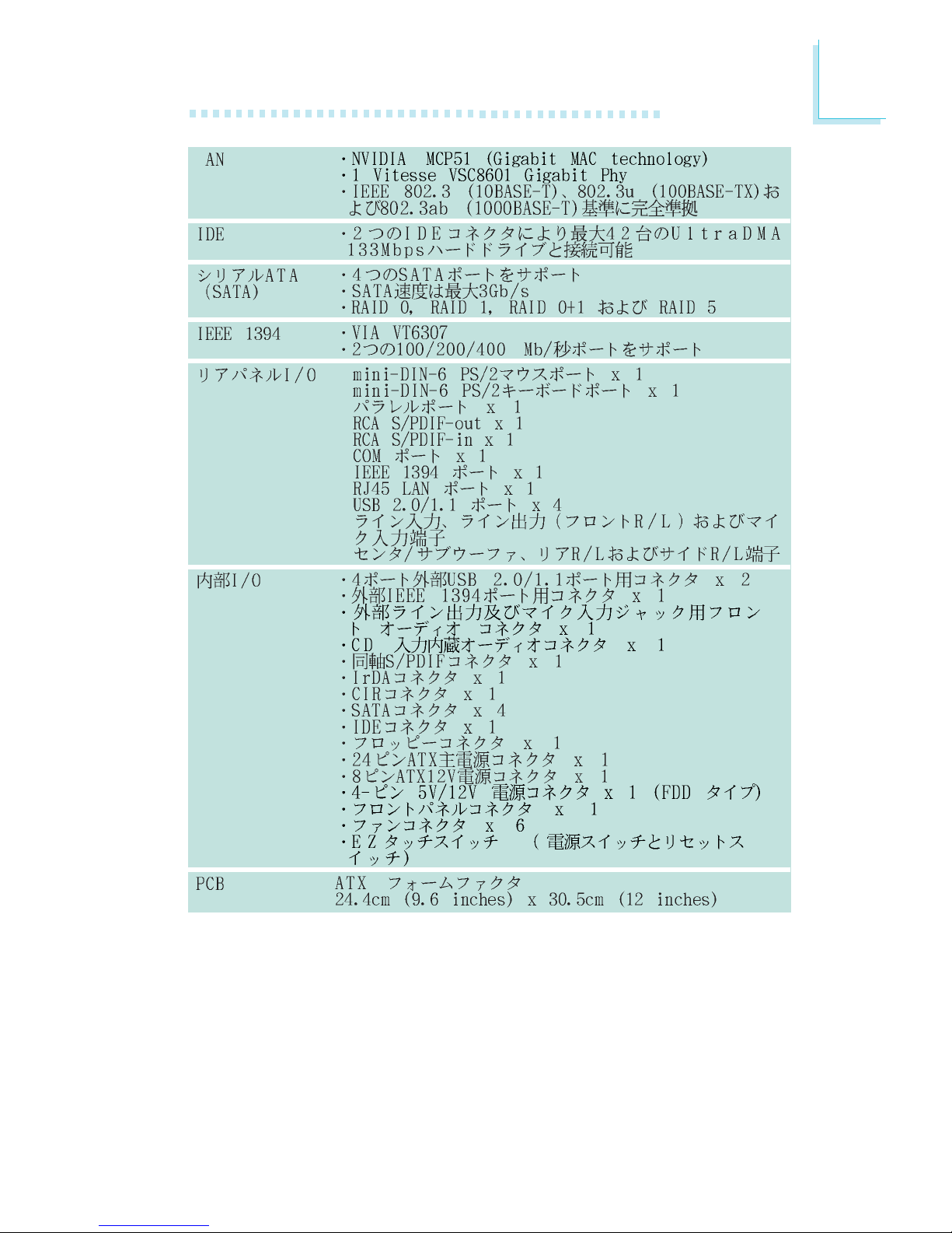
• NVIDIA® MCP51 integrated with Gigabit MAC (Media Access
Control) technology
• One Vitesse VSC8601 Gigabit Phy chip
• Fully compliant to IEEE 802.3 (10BASE-T), 802.3u (100BASETX) and 802.3ab (1000BASE-T) standards
• Realtek ALC885 High Definition audio CODEC
• 8-channel audio output
• DAC SNR/ADC SNR of 106dB/101dB
• Full-rate lossless content protection technology
• S/PDIF-in/out interface
• One IDE connector allows connecting up to 2 UltraDMA
133Mbps hard drives
• Four Serial ATA ports
• SATA speed up to 3Gb/s
• RAID 0, RAID 1, RAID 0+1 and RAID 5
• VIA VT6307
• Supports two 100/200/400 Mb/sec ports
• 1 mini-DIN-6 PS/2 mouse port
• 1 mini-DIN-6 PS/2 keyboard port
• 1 parallel port
• 1 RCA S/PDIF-out port
• 1 RCA S/PDIF-in port
• 1 COM port
• 1 IEEE 1394 port
• 1 RJ45 LAN port
• 4 USB 2.0/1.1 ports
• Line-in, line-out (front R/L) and mic-in jacks
• Center/subwoofer, rear R/L and side R/L jacks
• 2 connectors for 4 additional external USB 2.0/1.1 ports
• 1 connector for 1 external IEEE 1394 port
• 1 front audio connector
• 1 CD-in internal audio connector
• 1 S/PDIF connector for optical cable connection
• 1 IrDA connector
• 1 CIR connector
• 4 Serial ATA connectors
• 1 IDE connector
• 1 floppy connector
• 1 24-pin ATX power connector
• 1 8-pin 12V power connector
• 1 4-pin 5V/12V power connector (FDD type)
• 1 front panel connector
• 6 fan connectors
• EZ touch switches (power switch and reset switch)
• ATX form factor
• 24.4cm (9.6") x 30.5cm (12")
Page 12

Introduction
1
12
Features
The system board supports Intel processors with Hyper-Threading Technology. Ena-
bling the functionality of Hyper-Threading
Technology for your computer system requires ALL of the following
platforms.
Components:
• CPU - an Intel
®
Pentium® 4 Processor with HT Technology
• Chipset - an Intel® chipset that supports HT Technology
• BIOS - a BIOS that supports HT Technology and has it enabled
• OS - an operating system that includes optimizations for HT
Technology
For more information on Hyper-Threading Technology, go to:
www.intel.com/info/hyperthreading.
PCI Express is a high bandwidth I/O infrastructure
that possesses the ability to scale speeds by forming
multiple lanes. The system board currently supports
the physical layer of x1 and x16 lane widths.
The x1 PCI Express lane supports transfer rate of 2.5 Gigabytes
(250MBbps) per second. The PCI Express architecture also provides
a high performance graphics infrastructure by enhancing the capability
of a x16 PCI Express lane to provide 4 Gigabytes per second
transfer rate.
CPU Overheat Protection has the capability of
monitoring the CPU’s temperature during sys-
tem boot up. Once the CPU’s temperature
exceeded the temperature limit pre-defined by the CPU, the system
will automatically shutdown. This preventive measure has been added
to protect the CPU from damage and insure a safe computing environment.
CPU Overheat
Protection
hyper-threading
technology
Page 13
1
Introduction
13
DDR2 is a higher performance DDR technology whose
data transfer rate delivers bandwidth of 4.3 GB per second and beyond. That is twice the speed of the conven-
tional DDR without increasing its power consumption.
DDR2 SDRAM modules work at 1.8V supply compared to 2.6V
memory voltage for DDR modules. DDR2 also incorporates new
innovations such as the On-Die Termination (ODT) as well as larger
4-bit pre-fetch against DDR which fetches 2 bits per clock cycle.
The onboard Realtek ALC885 is a High Definition audio
codec and the 6 audio jacks at the rear I/O panel provides 8-channel audio output for advanced 7.1-channel
super surround sound audio system. ALC885 also supports S/PDIF output, allowing digital connections with DVD systems
or other audio/video multimedia.
S/PDIF is a standard audio file transfer format that transfers digital audio signals to a device without having to be
converted first to an analog format. This prevents the
quality of the audio signal from degrading whenever it is
converted to analog. S/PDIF is usually found on digital audio equipment such as a DAT machine or audio processing device. The
S/PDIF connector on the system board sends surround sound and
3D audio signal outputs to amplifiers and speakers and to digital
recording devices like CD recorders.
Serial ATA is a storage interface that is compliant with SATA 1.0 specification. NVIDIA
®
MCP51 supports speed of up to 3Gb/s. Serial ATA improves hard
drive performance faster than the standard parallel ATA whose data
transfer rate is 100MB/s.
The NVIDIA
®
MCP51 chip allows configuring RAID on
Serial ATA drives. It supports RAID 0, RAID 1, RAID 0+1
and RAID 5.
Page 14
Introduction
1
14
Wake-On-LAN
IrDA
The Gigabit MAC (Media Access Control) technology integrated in NVIDIA® MCP51 and the external Vitesse
VSC8601 Gigabit Phy supports up to 1Gbps.
IEEE 1394 is fully compliant with the 1394 OHCI (Open
Host Controller Interface) 1.1 specification. It supports up
to 63 devices that can run simultaneously on a system.
1394 is a fast external bus standard that supports data
transfer rates of up to 400Mbps. In addition to its high speed, it
also supports isochronous data transfer which is ideal for video devices that need to transfer high levels of data in real-time. 1394
supports both Plug-and-Play and hot plugging.
The system board is equipped with an IrDA connector
for wireless connectivity between your computer and
peripheral devices. The IRDA (Infrared Data Association) specification
supports data transfers of 115K baud at a distance of 1 meter.
The system board supports USB 2.0 and USB 1.1
ports. USB 1.1 supports 12Mb/second bandwidth
while USB 2.0 supports 480Mb/second bandwidth
providing a marked improvement in device transfer
speeds between your computer and a wide range of simultaneously
accessible external Plug and Play peripherals.
This feature allows the network to remotely
wake up a Soft Power Down (Soft-Off) PC.
It is supported via the onboard LAN port or via a PCI LAN card
that uses the PCI PME (Power Management Event) signal. However,
if your system is in the Suspend mode, you can power-on the system
only through an IRQ or DMA interrupt.
Important:
The 5VSB power source of your power supply must support
≥
720mA.
Page 15

1
Introduction
15
This function allows you to use the PS/2 keyboard or PS/2 mouse to power-on the sys-
tem.
Important:
The 5VSB power source of your power supply must support
≥
720mA.
The RTC installed on the system board allows your
system to automatically power-on on the set date and
time.
The system board is designed to meet the ACPI (Ad-
vanced Configuration and Power Interface) specification.
ACPI has energy saving features that enables PCs to implement
Power Management and Plug-and-Play with operating systems that
support OS Direct Power Management. Currently, only Windows
®®
®®
®
2000/XP supports the ACPI function. ACPI when enabled in the
Power Management Setup will allow you to use the Suspend to
RAM function.
With the Suspend to RAM function enabled, you can power-off the
system at once by pressing the power button or selecting “Standby”
when you shut down Windows
®®
®®
®
2000/XP without having to go
through the sometimes tiresome process of closing files, applications
and operating system. This is because the system is capable of storing all programs and data files during the entire operating session
into RAM (Random Access Memory) when it powers-off. The operating session will resume exactly where you left off the next time you
power-on the system.
Important:
The 5VSB power source of your power supply must support
≥
1A.
When power returns after an AC power failure, you may choose to either power-on the
system manually, let the system power-on automatically or return to the state where you left off before power
failure occurs.
Wake-On-PS/2
rtc
str
power failure
recovery
Page 16

Introduction
1
16
Français
Processeur
Chipset
Mémoire Système
Logements
d’Extension
BIOS
Gestion de
Puissance
Fonctions de
Moniteur de
Matériel
• LGA 775 socket pour:
- Intel® CoreTM2 Quad, Intel® CoreTM2 Extreme, Intel® CoreTM2
Duo, Intel® Pentium® D ou Intel® Pentium® 4
• Intel Ont augmenté La Technologie De la Mémoire 64
(EMT64T)
• Ont augmenté La Technologie D’Intel SpeedStep (EIST)
• Intel Hyper-Filetant La Technologie (Intel Hyper-Threading)
• Soutient 1333*1066/800MHz FSB
*Disponible sur les unités centrales de traitement qui
soutiennent 1333MHz FSB
• NVIDIA nForce
®
650i Ultra MCP
- Pont nord: NVIDIA® 650i Ultra
- Pont sud: NVIDIA® MCP51
• 4 sockets DIMM DDR2 240-pin
• Les modules DIMM DDR2 533/667/800
• L’interface de mémoire deux canaux (128-bit)
• Jusqu’à 8GB de mémoire système
• Exclusivement les modules DIMM non-ECC x8 et x16
• Les DIMM non-tamponnés
• 1 slot PCI Express x16
• 2 slots PCI Express x1
• 3 slots PCI
• Compatible avec Award BIOS
• Mémoire Flash 8Mbit
• ACPI et OS Directed Power Management
• ACPI STR (Suspend to RAM) fonction
• Réveil-Sur-PS/2 Clavier/Souris
• Eveil Sonnerie
• Minuterie RTC pour allumer le système
• Récupération après Défaillance d’Alimentation CA
• Gère l’alarme de température et de surchauffe de CPU/
système/chipset
• Gère l’alarme de voltage et d’échec de 12V/5V/3.3V/Vcore/
Vbat/5Vsb/Vdimm/Vchip
• Gère la vitesse de ventilateur du ventilateur
• Protection du CPU - supporte la mise hors circuit automatique
en cas de surchauffage du système
Caractéristiques et Spécifications
Page 17

1
Introduction
17
LAN
Audio
IDE
Serial ATA avec
RAID
EE 1394
Panneau Arrière
I/O
Interne I/O
PCB
• NVIDIA® MCP51 avec la technologie integrée Gigabit MAC
(Media Access Control)
• 1 Vitesse VSC8601 Gigabit Phy
• Supporte IEEE 802.3 (10BASE-T), 802.3u (100BASE-TX) et
802.3ab (1000BASE-T)
• Realtek ALC885 8-canaux Définition Élevée audio CODEC
• DAC SNR/ADC SNR de 106dB/101dB
• Technologie protection de contente lossless à toute vitesse
• Interface entrée/sor tie S/PDIF
• Supporte des disques durs jusqu’à UltraDMA 133Mbps
• 4 ports de série ATA
• Vitesse SATA jusqu’à 3Gb/s
• RAID 0, RAID 1, RAID 0+1 et RAID 5
• VIA VT6307
• Supporte 2 100/200/400 Mb/sec ports
• 1 mini-DIN-6 PS/2 mouse port
• 1 mini-DIN-6 PS/2 keyboard port
• 1 parallel port
• 1 RCA S/PDIF-out port
• 1 RCA S/PDIF-in port
• 1 COM port
• 1 IEEE 1394 port
• 1 RJ45 LAN port
• 4 USB 2.0/1.1 ports
• Line-in, line-out (front R/L) et mic-in jacks
• Center/subwoofer, rear R/L et side R/L jacks
•
2 connecteurs pour 4 ports USB 2.0/1.1 supplémentaires
• 1 connecteur pour 1 IEEE 1394
• 1 connecteur audio frontal
•1 connecteur CD-in
• 1 S/PDIF l’assemblage pour l’adjonction de câble optique
• 1 connecteur IR
• 1 connecteur CIR
•4 connecteurs Serial ATA
• 1 connecteur IDE
• 1 connecteur de FDD
• 1 connecteur d’alimentation 24-pin ATX
• 1 connecteur d’alimentation 8-pin 12V ATX
• 1 prises d’alimentation 4-broches 5V/12V (type-FDD)
• 1 connecteur devant panneau
• 6 connecteurs de ventilateurs
• EZ interrupteurs (bouton de power et reset)
• Facteur de forme de ATX
• 24.4cm (9.6") x 30.5cm (12")
Page 18

Introduction
1
18
Deutsch
Prozessor
Chipset
Systemspeicher
Expansion Schlitz
BIOS
Energie
Management
Kleinteilmonitor
• LGA 775 CPU Einfaßung für:
- Intel® CoreTM2 Quad, Intel® CoreTM2 Extreme, Intel® CoreTM2
Duo, Intel® Pentium® D oder Intel® Pentium® 4
• Intel Erhöhten Technologie Des Gedächtnis-64 (EMT64T)
• Erhöhten Intel SpeedStep Technologie (EIST)
• Intel, das Technologie Hyper-Verlegt (Intel Hyper-Threading)
• Stützt 1333*/1066/800MHz FSB
*Verfügbar für CPU’s die 1333 MHz. FSB unterstützen
• NVIDIA nForce
®
650i Ultra MCP
- Nordbrücke: NVIDIA® 650i Ultra
- Südbrücke: NVIDIA® MCP51
• 4 Sockel 240-pin DDR2 DIMM
• DDR2 533, DDR2 667 und DDR2 800 DIMMs
• 128-bit – Speiher mit den zwei Kanälen
• Bis zum 8GB-Systemspeicher
• Nur non-ECC x8 und x16 ohne Dämpfer DIMMs
• 1 PCI Express x16-Einbauplätzen
• 2 PCI Express x1-Einbauplätzen
• 3 PCI-Einbauplätzen
• Kompatibilität mit Award BIOS
• Flash-Speicher (8Mbit)
• ACPI und OS Directed Power Management
• ACPI STR (Suspend to RAM) funktion
• Wecken bei Betätigung der PS/2 Tastatur/Maus
• Wecken des Systems durch das Netzwerk
• RTC-Taktgeber zum Einschalten des Systems
• Wiederherstellung der Wechselstromversorgung nach einem Ausfall
• Überwachung der Temperatur des CPU/Systems/Chipset sowie
Warnsignal bei Überhitzung
• Überwachung der Spannungen des 12V/5V/3.3V/Vcore/Vbat/
5Vsb/Vdimm/Vchip
• Überwachung der Geschwindigkeit des Ventilators
• Prozessor-Shutz - Die Ausschaltung bei der Überhitzung – die
automatische Ausschaltung des Computers bei der Überhitzung
Leistungsmerkmale und Technische Daten
Page 19

1
Introduction
19
LAN
Audio
IDE
Serial ATA mit RAID
IEEE 1394
Porte an der
Rückwand
Internes I/O
PCB
• NVIDIA® MCP51 integriert mit Gigabit MAC (Media Access
Control) Technologie
• 1 Vitesse VSC8601 Gigabit Phy
• Unterstützt IEEE 802.3 (10BASE-T), 802.3u (100BASE-TX) und
802.3ab (1000BASE-T)
• Realtek ALC885 8-Kanal-Hohe-Definition-audio-CODEC
• DAC SNR/ADC SNR von 106dB/101dB
• Lossless zufriedene Schutzvollwegtechnologie
• S/PDIF-In/Aus-Schnittstelle
• Unterstützung der Festplatten bis zum UltraDMA 133Mbps
• 4 serielle Serial ATA-Ports
• SATA bis zu 3Gb/s schnell
• RAID 0, RAID 1, RAID 0+1 und RAID 5
• VIA VT6307
• Unterstützt 2 100/200/400 Mb/sec porte
• 1 Mini-DIN-6-Anschluß für eine PS/2-Maus
• 1 Mini-DIN-6-Anschluß für eine PS/2-Tastatur
• 1 DB-25-Parallelanschluß
• 1 S/PDIF-out RCA-Anschlüsse
• 1 S/PDIF-in RCA-Anschlüsse
• 1 COM-Anschlüsse
• 1 IEEE-1394-Anschlüsse
• 1 RJ45 LAN-Anschlüsse
• 4 USB 2.0/1.1-Anschlüsse
• Line-in, line-out und mic-in Audio-Anschlußbuchsen
• Center/subwoofer, rear R/L und side R/LAudio-Anschlußbuchsen
•2
Anschlußfassung für 4 zusätzliche externe USB 2.0/1.1-Anschlüsse
• 1 Anschluß für eine externe IEEE 1394 Schnittstelle
• 1 Front-Audioanschluss
• 1 CD-in interne Audioanschlüsse
• 1 S/PDIF Anschluß für die Verbindung des optischen Kabel
• 1 Anschluß für die IR-Schnittstelle
• 1 CIR-Schnittstelle
• 4 Serial ATA-Anschlüsse
• 1 IDE-Anschlüsse
• 1 Floppy-Anschlüsse
• 1 24-polige Anschlußstecker für das ATX-Netzgerät
• 1 8-polige 12V Anschlußstecker für das ATX-Netzgerät
• 1 4-polige 5V/12V Netzstecker (für FDD)
• 1 Vorderseite Füllung Anschlüsse
• 6-ventilator-Anschlüsse
• EZ Umschaltern (der Knopf der Speisung und des Auslasses)
• ATX Formfaktor
• 24.4cm (9.6") x 30.5cm (12")
Page 20

Introduction
1
20
Español
Procesador
Chipset
Memoria de Sistema
Ranuras de
Expansión
BIOS
Gerencia de la
Energía
Monitor del
Hardware
• LGA 775 Zócalo de la CPU para:
- Intel® CoreTM2 Quad, Intel® CoreTM2 Extreme, Intel® CoreTM2
Duo, Intel® Pentium® D o Intel® Pentium® 4
• Intel Realzaron Tecnología De la Memoria 64 (EMT64T)
• Realzaron La Tecnología De Intel SpeedStep (EIST)
• Intel Hiperactivo-Que rosca Tecnología (Intel Hyper-Threading)
• 1333*1066/800MHz FSB
*Disponible en procesadores que soporten un FSB a 1333MHz
• NVIDIA nForce
®
650i Ultra MCP
- Puente norte: NVIDIA® 650i Ultra
- Puente sur: NVIDIA® MCP51
• 4 240-pin DDR2 DIMM asientos
• DDR2 533, DDR2 667 y DDR2 800 DIMMs
• Memoria de dos canales (128-bit)
• Hasta 8GB de memoria sistémica
• Sólo non-ECC x8 y x16 unbuffered DIMM
• 1 slot PCI Express x16
• 2 slot PCI Express x1
• 3 slots PCI
• Award BIOS
• Memoria Instante (8Mbitios)
• ACPI y OS Directed Power Management
• ACPI STR (Suspend to RAM) función
• PS/2 Teclado/Ratón de Wake-On
• Wake-On-LAN
• Temporizador de RTC para encender el sistema
• Recuperación de Fracaso de Energía AC
• Monitores de los CPU/sistema/chipset temperaturas y alarma
acalorada.
•Monitores de voltajes de 12V/5V/3.3V/Vcore/Vbat/5Vsb/
Vdimm/Vchip
• Vigila la velocidad del abanico del abanido
•Protección del procesador - Desconección en caso de
recalentamiento –el ordenador se desconecta automáticamente
en caso de recalentamiento
Características y Especificaciones
Page 21

1
Introduction
21
LAN
Audio
IDE
Serial ATA con
RAID
IEEE 1394
Panel Trasero I/O
Conectador Interno
PCB
• NVIDIA® MCP51 integrado con la tecnología Gigabit MAC
(Media Access Control)
• 1 Vitesse VSC8601 Gigabit Phy
• Completamente a IEEE 802.3 (10BASE-T), 802.3u (100BASETX) y 802.3ab (1000BASE-T) estándar
• Realtek ALC885 8-canal Alta Definición audio CODEC
• DAC SNR/ADC SNR de 106dB/101dB
• Tecnología protección de la contenta lossless de exploración
completa
• Interfáz de S/PDIF-in/out
•Soporta las unidades duras hasta de UltraDMA 133Mbps
• 4 ports de Serial ATA
• SATA se acelera a 3Gb/s
• RAID 0, RAID 1, RAID 0+1 y RAID 5
• VIA VT6307
• Soporta 2 ports 100/200/400 Mb/sec
• 1 puerto de ratón mini-DIN-6 PS/2
• 1 puerto de teclado mini-DIN-6 PS/2
• 1 puerto paralelo de DB-25
• 1 puerto de S/PDIF-out RCA
• 1 puerto de S/PDIF-in RCA
• 1 puerto COM
• 1 puerto de IEEE 1394
• 1 puerto de RJ45 LAN
• 4 puertos de USB 2.0/1.1
• Line-in, line-out (front R/L) y mic-in enchufes de audio
• Center/subwoofer, rear R/L y side R/L enchufes de audio
• 2 conectores para 4 puertos de USB 2.0/1.1 externo adicional
• 1 conector para un puerto de IEEE 1394
• 1 connector de sonido delantera
• 1 conector de CD-in
• 1 S/PDIF mortaja para conección de cable óptico
• 1 conector de IR
• 1 conector de CIR
• 4 conectores de SATA
• 1 conectore de IDE
• 1 conector de FDD
• 1 conector 24-pin de fuente de alimentación de ATX
• 1 conector 8-pin 12V de fuente de alimentación de ATX
• 1 4-fichas conectador de energía de 5V/12V (FDD-tipo)
• 1 conector de panel delante
• 6 conectores de abanicos
• EZ conmutadores (conmutadores de alimentación y reset)
• ATX forme el factor,
• 24.4cm (9.6") x 30.5cm (12")
Page 22

Introduction
1
22
Русский языкРусский язык
Русский языкРусский язык
Русский язык
ПроцессорПроцессор
ПроцессорПроцессор
Процессор
ЧипсетЧипсет
ЧипсетЧипсет
Чипсет
ОперативнаяОперативная
ОперативнаяОперативная
Оперативная
ПамятьПамять
ПамятьПамять
Память
управлениеуправление
управлениеуправление
управление
силыñèëû
ñèëûñèëû
ñèëû
BIOSBIOS
BIOSBIOS
BIOS
управлениеуправление
управлениеуправление
управление
силыñèëû
ñèëûñèëû
ñèëû
монитормонитор
монитормонитор
монитор
оборудованияоборудования
оборудованияоборудования
оборудования
•LGA 775 гнездо для:
- Intel® CoreTM2 Quad, Intel® CoreTM2 Extreme, Intel
®
CoreTM2 Duo, Intel® Pentium® D èëè Intel® Pentium® 4
• Intel Увеличили Технологию Памяти 64 (EMT64T)
•Увеличили Технологию Intel SpeedStep (EIST)
•Intel Гипер-Prodeva4 нитку Технологию (Intel HyperThreading)
•1333*/1066/800MHz FSB
*Есть на процессорах, поддерживающих частоту
øèíû 1333ÌÃö
•NVIDIA nForce
®
650i Ultra MCP
- Северный мост: NVIDIA® 650i Ultra
- Южный мост: NVIDIA® MCP51
•4 240-pin DDR2 DIMM гнезда
•DDR2 533, DDR2 667 è DDR2 800 DIMMs
•двухканальную память (128-бит)
•до 8ГБ системной памяти
•только non-ECC x8 и x16 небуфф. DIMM
•1 PCI Express x16 слотов
•2 PCI Express x1 слотов
•3 PCI слотов
•Award BIOS
•8Mbit Flash Память
•ACPI è OS Directed Power Management
•ACPI STR (Suspend to RAM)
•Активизация На Движение Мыши
•Активизация На Входящий Звонок
•RTC Таймер для Включения Системы
• Скачки Напряжения
• Mониторинг температуры процессора/системы/
Чипсет
•Mониторинг напряжений 12V/5V/3.3V/Vcore/Vbat/
5Vsb/Vdimm/Vchip
•Mониторинг скорости вращения вентилятора
•Защита процессора - Выключение при перегреве –
автоматическое выключение компьютера при
перегреве
Характеристики и свойстваХарактеристики и свойства
Характеристики и свойстваХарактеристики и свойства
Характеристики и свойства
Page 23

1
Introduction
23
LANLAN
LANLAN
LAN
тональнозвуковотональнозвуково
тональнозвуковотональнозвуково
тональнозвуково
IDEIDE
IDEIDE
IDE
Serial ASerial A
Serial ASerial A
Serial A
TT
TT
T
A cA c
A cA c
A c
RAIDRAID
RAIDRAID
RAID
IEEE 1394IEEE 1394
IEEE 1394IEEE 1394
IEEE 1394
задняя панельзадняя панель
задняя панельзадняя панель
задняя панель
I/OI/O
I/OI/O
I/O
внутренне внутренне
внутренне внутренне
внутренне
I/OI/O
I/OI/O
I/O
PCBPCB
PCBPCB
PCB
•NVIDIA® MCP51 со встроенной технологией Gigabit
MAC (Media Access Control)
•1 Vitesse VSC8601 Gigabit Phy
•Поддерживает IEEE 802.3 (10BASE-T), 802.3u
(100BASE-TX) и 802.3ab (1000BASE-T)
• Realtek ALC885 8-канал Высокое Определение
CODEC
•DAC SNR/ADC SNR 106dB/101dB
•Full-rate lossless содержимая технология
предохранения
•интерфейса S/PDIF-in/out
•Поддерживает жесткие диски до UltraDMA 133Mbps
•4 SATA портов
•Скорость SATA до 3 ГБ/с
•RAID 0, RAID 1, RAID 0+1 è RAID 5
•VIA VT6307
•Поддерживает 2 100/200/400 Mb/sec порта
•1 ìèíè-DIN-6 PS/2 ïîðò äëÿ ìûøè
•1 мини-DIN-6 PS/2 порт для клавиатуры
•1 DB-25 параллельный порт
•1 S/PDIF-out RCA ïîðò
•1 S/PDIF-in RCA ïîðò
•1 COM ïîðò
•1 IEEE 1394 порта
•1 RJ45 LAN ïîðò
•4 USB 2.0/1.1 порта
•Mic-in, line-in и line-out гнезда для звука
•Center/subwoofer, rear R/L и side R/L гнезда для звука
•2 разъем для 4-х дополнительных внешних USB 2.0/
1.1 портов
•1 разъем для внешнего IEEE 1394 порта
•1 фронтальный аудио-разъем
•1 CD-in разъема
•1 S/PDIF разъем для присоединения оптического
кабеля
•1 IR разъем
•1 CIR разъем
•4 Serial ATA разъема
• 1 IDE разъема
• 1 разъем FDD
•1 24-штырьковых разъемов питания ATX
•1 8-штырьковых 12V разъемов питания ATX
•1 4-штырьковых разъемов питания 5V/12V (типа FDD)
•1 Фронт панель разъем
•6 Разъемы для вентилятора
•EZ переключатели (кнопка питания и сброса)
•ATX
•24.4cm (9.6") x 30.5cm (12")
Page 24
24
Introduction
1
•
® TM ® TM
® TM ®
®
®
®
•
•
•
•
*
•
®
®
®
•
•
•
•
•
•
•
•
•
•
•
•
•
•
•
•
•
•
•
•
•
•
•
•
Page 25
25
1
Introduction
L
®
•
•
•
•
•
•
•
•
•
•
•
Page 26
26
2
Hardware Installation
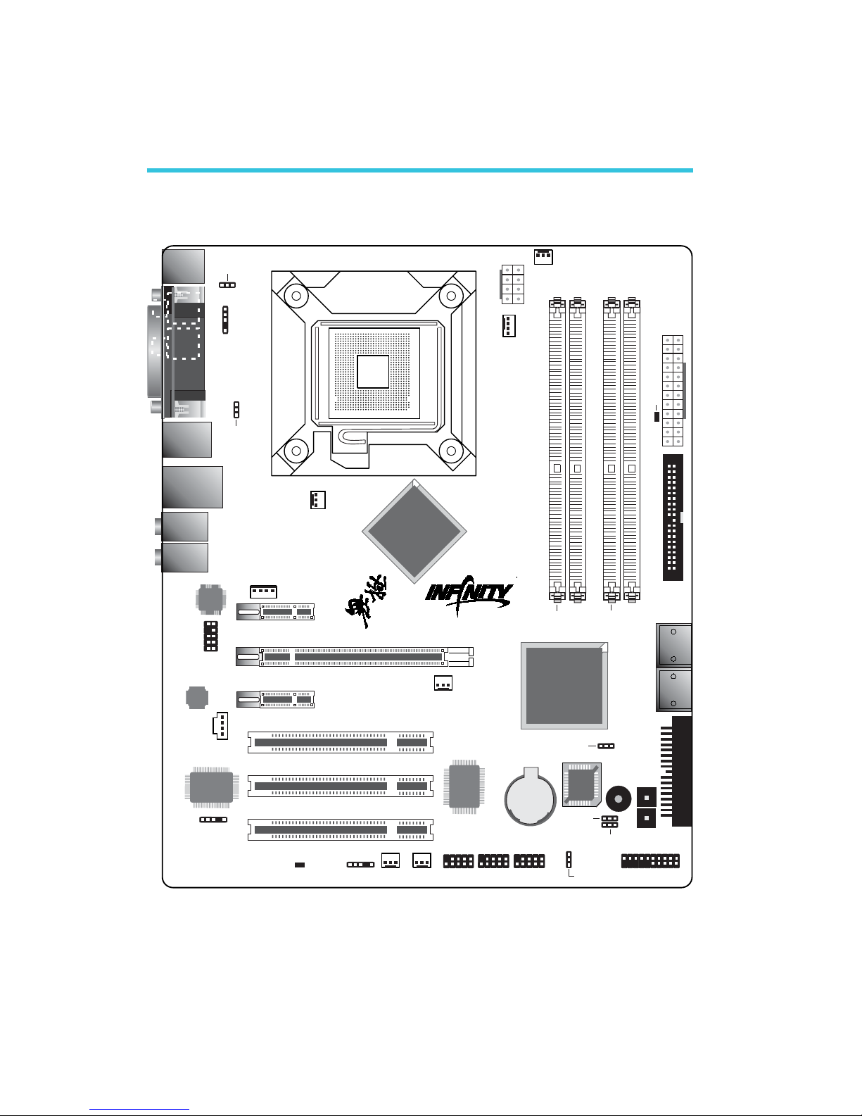
System Board Layout
Chapter 2 - Hardware Installation
Line-in
Front R/L
Mic-in
Center/Subwoofer
Side R/L
Rear R/L
40239
1
IDE
1
24
12
1
13
DDR2-1
DDR2-2
DDR2-3
DDR2-4
1
CD-in
1
PS/2 power
select ( )JP7
1
DRAM Power LED
1
Fan 2
USB 4-5
1
1
1
IrDA
Standby
Power LED
1
CIR
1
1
1
Fan 1
Front audio
1
Mouse
KB
1394-1
USB 0-1
LAN
USB 2-3
USB 0-3 power
select ( )JP5
1
BIOS
1
CPU fan
Fan 4
1
Reset
Power
Front panel
1
PCI 1
PCI 3
PCI 2
S/PDIF
in
S/PDIF
COM 1
out
Top: Parallel
PCIE 3
PCIE 2
1
S/PDIF
1
1
NB fan
1
PCIE 1
12V power
ATX po we r
LGA 775
5V/12V power
USB 4-7 power
select ( )JP6
Vitesse
VSC8601
ITE
IT8718F
Realtek
ALC885
VIA
VT6307
Battery
1394-2
NVIDIA
nForce 650i
ULTRA
NVIDIA
MCP51
4
5
8
Safe boot
(JP1)
Speaker
on/off (JP8)
1
Fan 3
USB 6-7
1
1
FDD
1
Clear CMOS
(JP2)
SATA 2
SATA 1
SATA 4
SATA 3
Page 27
27
2
Hardware Installation
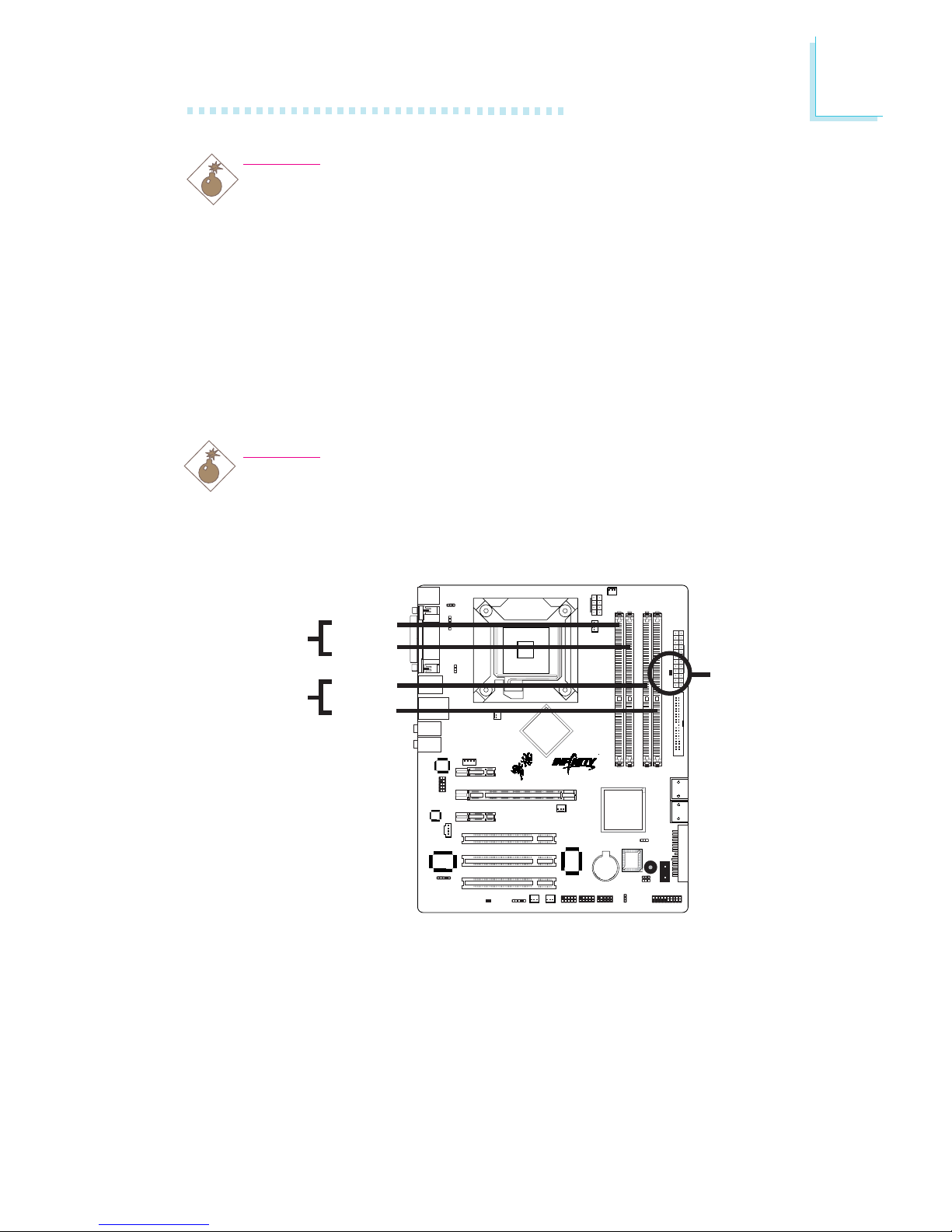
System Memory
Warning:
When the DRAM Power LED lit red, it indicates that power is
present on the DDR2 sockets. Power-off the PC then unplug the
power cord prior to installing any memory modules. Failure to do so
will cause severe damage to the motherboard and components.
Warning:
Electrostatic discharge (ESD) can damage your system board,
processor, disk drives, add-in boards, and other components. Perform
the upgrade instruction procedures described at an ESD workstation
only. If such a station is not available, you can provide some ESD
protection by wearing an antistatic wrist strap and attaching it to a
metal part of the system chassis. If a wrist strap is unavailable,
establish and maintain contact with the system chassis throughout
any procedures requiring ESD protection.
.
.
.
.
.
.
.
.
The system board supports 240-pin DDR2 DIMM sockets. The four
DDR2 DIMM sockets on the system board are divided into 2 channels:
Channel A - DDR2-1 and DDR2-2
Channel B - DDR2-3 and DDR2-4
.
.
.
.
.
.
.
.
40
2
39
1
DDR2-1
DDR2-2
DDR2-3
DDR2-4
DRAM
Power LED
Channel A
Channel B
Page 28

28
2
Hardware Installation
The system board supports the following memory interface.
Single Channel (SC)
Data will be accessed in chunks of 64 bits (8B) from the memory
channels.
Dual Channel (DC)
Data will be accessed in chunks of 128 bits from the memory channels. Dual channel provides better system performance because it
doubles the data transfer rate.
BIOS Setting
Configure the system memory in the Genie BIOS Setting submenu
(“Memory Timing Setting” section) of the BIOS.
• DIMMs are on the same channel.
• DIMMs in a channel can be identical or
completely different. However, we highly recommend using identical DIMMs.
• Not all slots need to be populated.
• DIMMs of the same memory configura-
tion are on different channels.
Single Channel
Dual Channel
Page 29
29
2
Hardware Installation
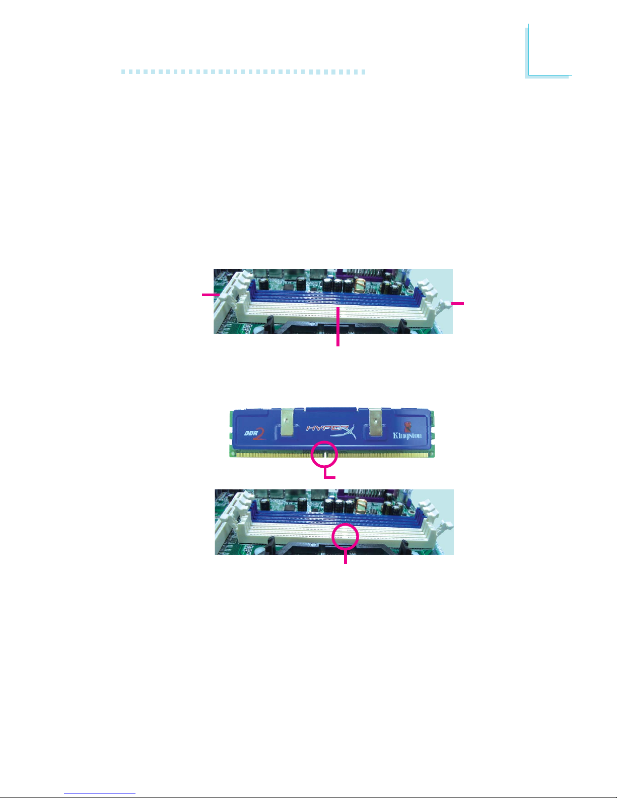
Installing the DIM Module
1. Make sure the PC and all other peripheral devices connected to
it has been powered down.
2. Disconnect all power cords and cables.
3. Locate the DDR2 socket on the system board.
4. Push the “ejector tabs” which are at the ends of the socket to
the side.
Ejector
tab
5. Note how the module is keyed to the socket.
DDR2 sockets
Ejector
tab
Key
Notch
Page 30
30
2
Hardware Installation
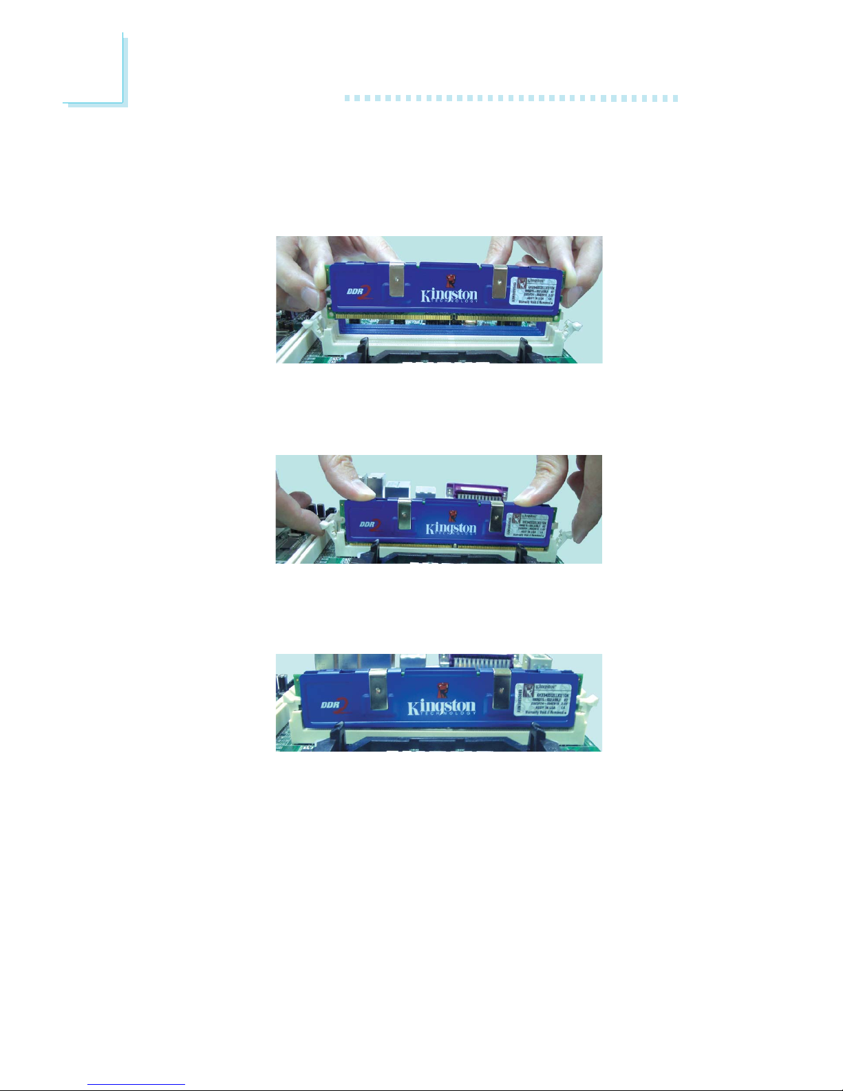
7. Seat the module vertically, pressing it down firmly until it is completely seated in the socket.
6. Grasping the module by its edges, position the module above
the socket with the “notch” in the module aligned with the “key”
on the socket. The keying mechanism ensures the module can be
plugged into the socket in only one way.
8. The ejector tabs at the ends of the socket will automatically
snap into the locked position to hold the module in place.
Page 31

31
2
Hardware Installation
CPU
Overview
The system board is equipped with a surface mount LGA 775
socket. This socket is exclusively designed for installing a LGA 775
packaged Intel CPU.
Important:
1. Before you proceed, make sure (1) the LGA7751. Before you proceed, make sure (1) the LGA775
1. Before you proceed, make sure (1) the LGA7751. Before you proceed, make sure (1) the LGA775
1. Before you proceed, make sure (1) the LGA775
socket comes with a protective cap, (2) the capsocket comes with a protective cap, (2) the cap
socket comes with a protective cap, (2) the capsocket comes with a protective cap, (2) the cap
socket comes with a protective cap, (2) the cap
is not damaged and (3) the socket’s contact pinsis not damaged and (3) the socket’s contact pins
is not damaged and (3) the socket’s contact pinsis not damaged and (3) the socket’s contact pins
is not damaged and (3) the socket’s contact pins
are not bent. If the cap is missing or the capare not bent. If the cap is missing or the cap
are not bent. If the cap is missing or the capare not bent. If the cap is missing or the cap
are not bent. If the cap is missing or the cap
and/or contact pins are damaged, contact yourand/or contact pins are damaged, contact your
and/or contact pins are damaged, contact yourand/or contact pins are damaged, contact your
and/or contact pins are damaged, contact your
dealer immediatelydealer immediately
dealer immediatelydealer immediately
dealer immediately
..
..
.
2.2.
2.2.
2.
Make sure to keep the protective cap. RMA re-Make sure to keep the protective cap. RMA re-
Make sure to keep the protective cap. RMA re-Make sure to keep the protective cap. RMA re-
Make sure to keep the protective cap. RMA requests will be accepted and processed only if thequests will be accepted and processed only if the
quests will be accepted and processed only if thequests will be accepted and processed only if the
quests will be accepted and processed only if the
LGA775 socket comes with the protective cap.LGA775 socket comes with the protective cap.
LGA775 socket comes with the protective cap.LGA775 socket comes with the protective cap.
LGA775 socket comes with the protective cap.
Installing the CPU
1. Make sure the PC and all other peripheral devices connected to
it has been powered down.
2. Disconnect all power cords and cables.
3. Locate the LGA 775 CPU socket on the system board.
40239
1
X
Page 32

32
2
Hardware Installation
4. The CPU socket comes with a cover that is attached with a removable protective cap. The cap is used to protect the CPU
socket against dust and harmful particles. Remove the protective
cap only when you are about to install the CPU.
Protective cap
Lever
6. Unlock the socket by pushing the lever down, moving it away from
the side tab of the socket, then lifting it up.
Cover
Lift this part up
5. Lift the protective cap from the location pointed below to detach
the cap from the cover.
Important:
The CPU socket must not come in contact with anything
other than the CPU. Avoid unnecessary exposure. Remove
the protective cap only when you are about to install the
CPU.
Lever liftedTa b
Page 33

33
2
Hardware Installation
7. Now lift the cover.
8. Position the CPU above the socket. The gold mark on the CPU
must align with pin 1 of the CPU socket.
Important:
Handle the CPU by its edges and avoid touching the pins.
Cover
Pin 1 of the socket
Gold mark
Page 34

34
2
Hardware Installation
9. Insert the CPU into the socket until it is seated in place. The
CPU will fit in only one orientation and can easily be inserted
without exerting any force.
Important:
Do not force the CPU into the socket. Forcing the CPU into
the socket may bend the pins and damage the CPU.
10. Once the CPU is in place, move the cover down.
Page 35

35
2
Hardware Installation
11. Push the lever down to lock the socket. The lever should hook
onto the side tab to indicate that the CPU is completely secured in the socket.
Page 36

36
2
Hardware Installation
Installing the Fan and Heat Sink
The CPU must be kept cool by using a CPU fan with heat sink.
Without sufficient air circulation across the CPU and heat sink, the
CPU will overheat damaging both the CPU and system board.
Note:
• Use only certified fan and heat sink.
• The fan and heat sink package usually contains the fan and
heat sink assembly, and an installation guide. If the installation procedure in the installation guide differs from the one
in this section, please follow the installation guide in the
package.
1. Before you install the fan / heat sink, you must apply a thermal
paste onto the top of the CPU. The thermal paste is usually
supplied when you purchase the CPU or fan heat sink assembly.
Do not spread the paste all over the surface. When you later
place the heat sink on top of the CPU, the compound will disperse evenly.
Do not apply the paste if the fan / heat sink already has a patch
of thermal paste on its underside. Peel the strip that covers the
paste before you place the fan / heat sink on top of the CPU.
Page 37

37
2
Hardware Installation
40239
1
3. Connect the CPU fan’s cable connector to the CPU fan connector on the system board.
Heat sink
Fan
Stud
Groove
2. Place the heat sink on top of the CPU. The 4 studs around the
heat sink which are used to secure the heat sink onto the system board must match the 4 mounting holes around the socket.
Position each stud so that the groove faces the heat sink then
push it down firmly until it clicks into place.
Note:
You will not be able to secure the fan and heat sink assembly in place if the groove is not facing the heat sink.
Mounting
hole
Mounting
hole
Mounting
hole
Mounting
hole
Page 38

38
2
Hardware Installation
Jumper Settings
If you encounter the following,
a) CMOS data becomes corrupted.
b) You forgot the supervisor or user password.
c) You are unable to boot-up the computer system because the
processor’s clock was incorrectly set in the BIOS.
you can reconfigure the system with the default values stored in the
ROM BIOS.
To load the default values stored in the ROM BIOS, please follow
the steps below.
1. Power-off the system and unplug the power cord.
2. Set JP2 pins 2 and 3 to On. Wait for a few seconds and set JP2
back to its default setting, pins 1 and 2 On.
3. Now plug the power cord and power-on the system.
If your reason for clearing the CMOS data is due to incorrect
setting of the processor’s clock in the BIOS, please proceed to
step 4.
Clear CMOS Data
Clearing CMOS Data using JP2
40
2
39
1
X
JP2
2-3 On:
Clear CMOS Data
1-2 On: Normal
(default)
3
1
2
31
2
Page 39

39
2
Hardware Installation
4. After powering-on the system, press <Del> to enter the main
menu of the BIOS.
5. Select the Genie BIOS Setting submenu and press <Enter>.
6. Set the processor’s clock to its default setting or an appropriate
setting. Refer to the Genie BIOS Setting section in chapter 3 for
more information.
7. Press <Esc> to return to the main menu of the BIOS setup
utility. Select “Save & Exit Setup” and press <Enter>.
8. Type <Y> and press <Enter>.
Page 40

40
2
Hardware Installation
PS/2 Power Select
JP7 is used to select the power of the PS/2 keyboard/mouse port.
Selecting 5VSB will allow you to use the PS/2 keyboard or PS/2
mouse to wake up the system.
BIOS Setting
Configure the PS/2 keyboard/mouse wake up function in the Integrated Peripherals submenu (“Onboard Super IO Device” section) of
the BIOS. Refer to chapter 3 for more information.
Important:
The 5VSB power source of your power supply must support
≥
720mA.
40
2
39
1
X
JP7
2-3 On: 5VSB
1-2 On: 5V
(default)
13
2
132
Page 41

41
2
Hardware Installation
40239
1
JP5 and JP6 are used to select the power of the USB ports.
Selecting 5VSB will allow you to use the USB keyboard or USB
mouse to wake up the system..
Important:
If you are using the Wake-On-USB Keyboard/Mouse function for
2 USB ports, the 5VSB power source of your power supply
must support ≥1.5A. For 3 or more USB ports, the 5VSB
power source of your power supply must support ≥2A.
USB Power Select
X
USB 0-3
(JP5)
X
USB 4-7
(JP6)
2-3 On:
5VSB
1-2 On: 5V
(default)
2-3 On:
5VSB
1-2 On: 5V
(default)
1
3
2
1
3
2
1
3
2
1
3
2
Page 42

42
2
Hardware Installation
40
2
39
1
The system board is equipped with a buzzer which serves as the
PC’s speaker. By default the buzzer is “on” allowing you to hear the
system’s beep messages and warnings. If you intend to use an
external speaker, turn this function off by setting JP8 pins 1 and 2 to
On.
Speaker On/Off Select
X
JP8
2-3 On:
Speaker On
(default)
1-2 On:
Speaker Off
Buzzer
3
12
312
Page 43

43
2
Hardware Installation
40
2
39
1
JP1 is used to safely reboot the system whenever the system hangs
and you are unable to restart the system.
1. Power-off the system and unplug the power cord.
2. Set JP1 pins 2 and 3 to On. Wait for a few seconds then set
JP1 back to its default setting, pins 1 and 2 On.
3. Plug the power cord and power-on the system. The system will
reboot normally without losing all data stored in the CMOS.
Safe Boot
1-2 On:
Default
312
312
X
JP1
2-3 On:
Safe boot
Page 44

44
2
Hardware Installation
Rear Panel I/O Ports
The rear panel I/O ports consist of the following:
• PS/2 mouse port
• PS/2 keyboard port
• Parallel Port
• RCA S/PDIF-out jack
• RCA S/PDIF-in jack
• COM port
• IEEE 1394 port
• USB ports
• LAN port
• Line-in port
• Front R/L port
• Mic-in port
• Center/Subwoofer port
• Rear R/L port
• Side R/L port
PS/2
Mouse
PS/2
K/B
COM
S/PDIF-in
S/PDIF-out
USB 0-1
USB 2-3
IEEE
1394
RJ45
LAN
Parallel
Line-in
Center/
Subwoofer
Front R/L
Mic-in
Rear R/L
Side R/L
Page 45

45
2
Hardware Installation
PS/2 Mouse and PS/2 Keyboard Ports
The PS/2 mouse (Green) and PS/2 keyboard (Purple) ports are
both at location CN2 of the system board. The PS/2 mouse port
uses IRQ12. If a mouse is not connected to this port, the system
will reserve IRQ12 for other expansion cards.
Warning:
Make sure to turn off your computer prior to connecting or
disconnecting a mouse or keyboard. Failure to do so may
damage the system board.
Wake-On-PS/2 Keyboard/Mouse
The Wake-On-PS/2 Keyboard/Mouse function allows you to use the
PS/2 keyboard or PS/2 mouse to power-on the system. To use this
function:
• Jumper Setting:
JP7 must be set to “2-3 On: 5VSB”. Refer to “PS/2 Power
Select” in this chapter for more information.
• BIOS Setting:
Configure the PS/2 wake up function in the Integrated Peripherals
submenu (“Onboard Super IO Device” section) of the BIOS. Refer to chapter 3 for more information.
.
.
.
.
.
.
.
.
W
PS/2 Mouse
PS/2 Keyboard
40239
1
Page 46

46
2
Hardware Installation
Parallel Port
The standard parallel port (Burgundy) is at location CN12 for interfacing your PC to a parallel printer. It supports SPP, ECP and EPP.
BIOS Setting
Configure the parallel port in the Integrated Peripherals submenu
(“Onboard Super IO Device” section) of the BIOS. Refer to chapter
3 for more information.
Setting
SPP
(Standard Parallel Port)
ECP
(Extended Capabilities Port)
EPP
(Enhanced Parallel Port)
Function
Allows normal speed operation but
in one direction only.
Allows parallel port to operate in
bidirectional mode and at a speed
faster than the SPP’s data transfer
rate.
Allows bidirectional parallel port operation at maximum speed.
Parallel
W
40239
1
Page 47

47
2
Hardware Installation
40239
1
S/PDIF
The RCA S/PDIF-out jack and RCA S/PDIF-in jack are at locations
CN7 and CN5 respectively. The connector at location J3 is for
optical S/PDIF connection. S/PDIF ports are used to connect audio
output devices.
Your optical S/PDIF may come mounted on a card-edge bracket.
Install the card-edge bracket to an available slot at the rear of the
system chassis then connect the audio cable connector to J3. Make
sure pin 1 of the audio cable connector is aligned with pin 1 of J3.
Important:
DO NOT use optical S/PDIF and coaxial RCA S/PDIF at the
same time.
W
W
Optical
S/PDIF
S/PDIF-in
S/PDIF-out
1
5
+5V
Key
SPDIF out
GND
SPDIF in
Page 48

48
2
Hardware Installation
COM Port
The onboard serial port is at location CN1. The serial port is
RS-232 asynchronous communication port with 16C550A-compatible UARTs that can be used with modems, serial printers, remote
display terminals, and other serial devices.
BIOS Setting
Configure the serial port in the Integrated Peripherals submenu
(“Onboard Super IO Device” section) of the BIOS. Refer to chapter
3 for more information.
COM
W
40
2
39
1
Page 49

49
2
Hardware Installation
40239
1
The onboard IEEE 1394 port is at location CN3 (IEEE 1394-1) of
the system board.
The IEEE 1394 connector at location J8 (1394-2) is for connecting
an additional 1394 device. The 1394 port may come mounted on a
card-edge bracket. Install the card-edge bracket to an available slot
at the rear of the system chassis then insert the connector that is
attached to the 1394 port cable to J8. Make sure pin 1 of the
cable connector is aligned with pin 1 of the J8.
IEEE 1394
W
W
1394-2
1394-1
1
2
10
9
TPA+
TPA-
Ground
Ground
TPB- TPB+
Key
+12V (fused)
+12V (fused)
Ground
Page 50

50
2
Hardware Installation
40239
1
Universal Serial Bus Ports
The system board supports 8 USB 2.0/1.1 ports. USB allows data
exchange between your computer and a wide range of
simultaneously accessible external Plug and Play peripherals.
Four onboard USB 2.0/1.1 ports (Black) are at locations CN3 (USB
0-1) and CN4 (USB 2-3) of the system board.
J33 (USB 4-5) and J18 (USB 6-7) connectors allow you to connect
4 additional USB 2.0/1.1 ports. The USB ports may come mounted
on a card-edge bracket. Install the card-edge bracket to an available
slot at the rear of the system chassis then insert the connector that
is attached to the USB port cables to J33 or 18.
BIOS Setting
Configure the onboard USB in the Integrated Peripherals submenu of
the BIOS. Refer to chapter 3 for more information.
W
USB 6-7
W
USB 1
USB 0
USB 3
USB 2
USB 4-5
1
210
9
VCC VCC
-Data
-Data
+Data
+Data
Ground
Ground
KeyN. C.
Page 51

51
2
Hardware Installation
Driver Installation
You may need to install the proper drivers in your operating system
to use the USB device. Refer to your operating system’s manual or
documentation for more information.
Refer to chapter 4 for more information about installing the USB 2.0
driver.
Wake-On-USB Keyboard/Mouse
The Wake-On-USB Keyboard/Mouse function allows you to use a
USB keyboard or USB mouse to wake up a system from the S3
(STR - Suspend To RAM) state. To use this function:
• Jumper Setting:
JP5 and/or JP6 must be set to “2-3 On: 5VSB”. Refer to “USB
Power Select” in this chapter for more information.
Important:
If you are using the Wake-On-USB Keyboard/Mouse function for
2 USB ports, the 5VSB power source of your power supply
must support ≥1.5A. For 3 or more USB ports, the 5VSB
power source of your power supply must support ≥2A.
Page 52

52
2
Hardware Installation
RJ45 LAN Port
The onboard LAN port is at location CN4 of the system board.
LAN allows the system board to connect to a local area network
by means of a network hub.
BIOS Setting
Configure the onboard LAN in the Integrated Peripherals submenu
of the BIOS. Refer to chapter 3 for more information.
Driver Installation
Install the LAN driver. Refer to chapter 4 for more information.
W
40239
1
LAN
Page 53

53
2
Hardware Installation
Rear Panel Audio
Line-in (Light Blue)
This jack is used to connect any audio devices such as Hi-fi set,
CD player, tape player, AM/FM radio tuner, synthesizer, etc.
Line-out - Front Right/Left Jack (Lime)
This jack is used to connect to the front right and front left
speakers of the audio system.
Mic-in Jack (Pink)
This jack is used to connect an external microphone.
Center/Subwoofer Jack (Orange)
This jack is used to connect to the center and subwoofer speakers of the audio system.
Audio
40
2
39
1
W
W
Rear audio
Front audio
Rear R/L
Center/
Subwoofer
Side R/L
Front R/L
Line-in
Mic-in
12
10
9
Mic-L
GND
Mic-R
Line-out-R
Front-sense
Line-out-L
Presence-signal
Mic-jack-sense
Key
Line-out-jack-sense
Page 54

54
2
Hardware Installation
Rear Right/Left Jack (Black)
This jack is used to connect to the rear right and rear left speakers of the audio system.
Side Right/Left Jack (Gray)
This jack is used to connect to the side left and side right speakers of the audio system.
Front Audio
The front audio connector (J22) allows you to connect to the lineout and mic-in jacks that are at the front panel of your system.
BIOS Setting
Configure the onboard audio in the Integrated Peripherals submenu
of the BIOS. Refer to chapter 3 for more information.
Driver Installation
Install the audio driver. Refer to chapter 4 for more information.
Page 55

55
2
Hardware Installation
I/O Connectors
CD-in Internal Audio Connector
The CD-in (J20) connector is used to receive audio from a CD-
ROM drive, TV tuner or MPEG card.
40
2
39
1
X
1
4
Right audio channel
Left audio channel
Ground
Ground
Page 56

56
2
Hardware Installation
Floppy Disk Drive Connector
The 900 floppy disk drive connector supports a standard floppy disk
drive. To prevent improper floppy cable installation, the floppy disk
header has a keying mechanism. The 34-pin connector on the floppy
cable can be placed into the header only if pin 1 of the connector is
aligned with pin 1 of the header.
Connecting the Floppy Disk Drive Cable
Install one end of the floppy disk drive cable into the shrouded
floppy disk header (J23) on the system board and the other endmost connector to the floppy disk drive. The colored edge of the
daisy chained ribbon cable should be aligned with pin 1 of J23.
BIOS Setting
Enable or disable this function in the Integrated Peripherals submenu
(“Onboard Super IO Device” section) of the BIOS. Refer to chapter
3 for more information.
40
2
39
1
X
Page 57

57
2
Hardware Installation
Serial ATA Connectors
• 4 Serial ATA ports
• SATA speed up to 3Gb/s
• RAID 0, RAID 1, RAID 0+1 and RAID 5
Connecting Serial ATA Cables
Connect one end of the Serial ATA cable to the Serial ATA connector and the other end to your Serial ATA device.
BIOS Setting
Configure Serial ATA in the Integrated Peripherals submenu (“RAID
Config” section) of the BIOS. Refer to chapter 3 for more information.
Configuring RAID
The system board allows configuring RAID on Serial ATA drives.
Refer to chapter 5 for steps in configuring RAID.
SATA 3-4
SATA 1-2
40239
1
Page 58

58
2
Hardware Installation
IDE Disk Drive Connector
The system board is equipped with a shrouded PCI IDE header
that will interface two Enhanced IDE (Integrated Drive Electronics)
disk drives. To prevent improper IDE cable installation, the shrouded
PCI IDE header has a keying mechanism. The 40-pin connector on
the IDE cable can be placed into the header only if pin 1 of the
connector is aligned with pin 1 of the header.
The IDE connector supports 2 devices, a Master and a Slave. Use
an IDE ribbon cable to connect the drives to the system board. An
IDE ribbon cable have 3 connectors on them, one that plugs into an
IDE connector on the system board and the other 2 connects to
IDE devices. The connector at the end of the cable is for the Master
drive and the connector in the middle of the cable is for the Slave
drive.
Connecting the IDE Disk Drive Cable
Install one end of the IDE cable into the IDE header (J25) on the
system board and the other connectors to the IDE devices.
Note:
Refer to your disk drive user’s manual for information about
selecting proper drive switch settings.
40239
1
X
40
39
21
Page 59

59
2
Hardware Installation
Adding a Second IDE Disk Drive
When using two IDE drives, one must be set as the master and the
other as the slave. Follow the instructions provided by the drive
manufacturer for setting the jumpers and/or switches on the drives.
The system board supports Enhanced IDE or ATA-2, ATA/33,
ATA/66, ATA/100 or ATA/133 hard drives. We recommend that you
use hard drives from the same manufacturer. In a few cases, drives
from two different manufacturers will not function properly when
used together. The problem lies in the hard drives, not the system
board.
Important:
If you encountered problems while using an ATAPI CD-ROM
drive that is set in Master mode, please set the CD-ROM drive
to Slave mode. Some ATAPI CD-ROMs may not be recognized
and cannot be used if incorrectly set in Master mode.
BIOS Setting
Configure the onboard IDE in the Integrated Peripherals submenu
(“IDE Function Setup” section) of the BIOS. Refer to chapter 3 for
more information.
Page 60

60
2
Hardware Installation
IrDA and CIR Connectors
Connect the cable connector from your IrDA/CIR module to the
IrDA connector (J5) or CIR connector (J15).
Note:
The sequence of the pin functions on some IrDA/CIR cable
may be reversed from the pin function defined on the system
board. Make sure to connect the cable connector to the IrDA/
CIR connector according to their pin functions.
BIOS Setting
Configure IrDA/CIR in the Integrated Peripherals submenu
(“Onboard Super IO Device” section) of the BIOS.
Driver Installation
You may need to install the proper drivers in your operating system
to use the IrDA/CIR function. Refer to your operating system’s
manual or documentation for more information.
40239
1
W
IrDA
W
51
VCC
N. C.
IRRX
Ground
IRTX
51
5VSB
N. C.
CIRRX
Ground
CIRTX
CIR
Page 61

61
2
Hardware Installation
Fan 3
13
Ground
Power
N. C.
Cooling Fan Connectors
Connect the CPU fan’s cable connector to the CPU fan connector
(J31) on the system board. Fan 1 (J9), Fan 2 (J6), Fan 3 (J32), Fan 4
(J12) and NB Fan (J30) are used to connect additional cooling fans.
The cooling fans will provide adequate airflow throughout the chassis
to prevent overheating the CPU and system board components.
BIOS Setting
The “PC Health Status” submenu of the BIOS will display the current
speed of the cooling fans. Refer to chapter 3 for more information.
40
2
39
1
X
X
X
X
X
X
NB Fan
Fan 4
CPU fan
4
1
Sense
Power
Ground
Speed
Control
31
Ground
Power
N. C.
1
3
Sense
Power
On/Off
Fan 1
13
Ground
Power
N. C.
N. C.
Fan 2
13
Ground
Power
Page 62

62
2
Hardware Installation
LEDs
DRAM Power LED
This LED will light when the system’s power is on.
Standby Power LED
This LED will light when the system is in the standby mode.
Warning:
When the DRAM Power LED and/or Standby Power LED lit red,
it indicates that power is present on the DDR2 sockets and/or
PCI slots. Power-off the PC then unplug the power cord prior to
installing any memory modules or add-in cards. Failure to do so
will cause severe damage to the motherboard and components.
.
.
.
.
.
.
.
.
40
2
39
1
DRAM
Power LED
Standby
Power LED
Page 63

63
2
Hardware Installation
40
2
39
1
Power Connectors
Use a power supply that complies with the ATX12V Power Supply
Design Guide Version 1.1. An ATX12V power supply unit has a
standard 24-pin ATX main power connector that must be inserted
onto CN10.
Your power supply unit may come with an 8-pin or 4-pin +12V
power connector. The +12V power enables the delivery of more
+12VDC current to the processor’s Voltage Regulator Module
(VRM). If available, it is preferable to use the 8-pin power; otherwise
connect a 4-pin power connector to CN11 as shown below.
X
131
12 24
+3.3VDC
+3.3VDC
COM
+5VDC
COM
+5VDC
COM
PWR_OK
+5VSB
+12VDC
+12VDC
+3.3VDC
+3.3VDC
-12VDC
COM
PS_ON#
COM
COM
COM
NC
+5VDC
+5VDC
+5VDC
COM
24-pin ATX
40239
1
X
8-pin +12V
+12V
Ground
8
5
4
1
Page 64

64
2
Hardware Installation
40
2
39
1
The FDD-type power connector provides additional power. If you
are using more than one graphics cards, we recommend that you
plug a power cable from your power supply unit onto the 5V/12V
power connector at location J1. This will provide more stability to the
entire system. The system board will still work even if the additional
power connector is not connected.
The system board requires a minimum of 300 Watt power supply
to operate. Your system configuration (CPU power, amount of
memory, add-in cards, peripherals, etc.) may exceed the minimum
power requirement. To ensure that adequate power is provided, we
strongly recommend that you use a minimum of 400 Watt (or
greater) power supply.
Important:
Insufficient power supplied to the system may result in instability or the add-in boards and peripherals not functioning properly. Calculating the system’s approximate power usage is important to ensure that the power supply meets the system’s
consumption requirements.
1
4
+5V
+12V
Ground
Ground
X
Page 65

65
2
Hardware Installation
Restarting the PC
Normally, you can power-off the PC by:
1. Pressing the power button at the front panel of the chassis.
or
2. Pressing the power switch that is on the system board (note: not
all system boards come with this switch).
If for some reasons you need to totally cut off the power supplied
to the PC, switch off the power supply or unplug the power cord.
Take note though that if you intend to restart it at once, please
strictly follow the steps below.
1. The time where power is totally discharged varies among power
supplies. It's discharge time is highly dependent on the system's
configuration such as the wattage of the power supply, the
sequence of the supplied power as well as the number of
peripheral devices connected to the system. Due to this reason,
we strongly recommend that you wait for the Standby Power
LED (refer to the “LEDs” section in this chapter for the location
of the Standby Power LED) to lit off.
2. After the Standby Power LED has lit off, wait for 6 seconds
before powering on the PC.
If the system board is already enclosed in a chassis which
apparently will not make the Standby Power LED visible, wait for
15 seconds before you restore power connections. 15 seconds is
approximately the time that will take the LED to lit off and the
time needed before restoring power.
The above will ensure protection and prevent damage to the
motherboard and components.
Page 66

66
2
Hardware Installation
40239
1
Front Panel Connectors
HD-LED: Primary/Secondary IDE LED
This LED will light when the hard drive is being accessed.
RESET: Reset Switch
This switch allows you to reboot without having to power off the
system thus prolonging the life of the power supply or system.
SPEAKER: Speaker Connector
This connects to the speaker installed in the system chassis.
ATX-SW: ATX Power Switch
Depending on the setting in the BIOS setup, this switch is a “dual
function power button” that will allow your system to enter the SoftOff or Suspend mode. Refer to “Soft-Off By PBTN” in the Power
Management Setup (Chapter 3).
X
J19
1
2
19
20
HD-LED
RESET
SPEAKER
PWR-LED
ATX-SW
Page 67

67
2
Hardware Installation
PWR-LED: Power/Standby LED
When the system’s power is on, this LED will light. When the system
is in the S1 (POS - Power On Suspend) or S3 (STR - Suspend To
RAM) state, it will blink every second.
Note:
If a system did not boot-up and the Power/Standby LED did
not light after it was powered-on, it may indicate that the CPU
or memory module was not installed properly. Please make
sure they are properly inserted into their corresponding socket.
Pin
3
5
14
16
8
10
18
20
7
9
13
15
17
19
2
4
6
HD-LED
(Primary/Secondary IDE LED)
Reserved
ATX-SW
(ATX power switch)
Reserved
RESET
(Reset switch)
SPEAKER
(Speaker connector)
PWR-LED
(Power/Standby LED)
Pin Assignment
HDD LED Power
HDD
N. C.
N. C.
PWRBT+
PWRBT-
N. C.
N. C.
Ground
H/W Reset
Speaker Data
N. C.
Ground
Speaker Power
LED Power (+)
LED Power (+)
LED Power (-) or Standby Signal
Page 68

68
2
Hardware Installation
40239
1
EZ Touch Switches
The presence of the power switch and reset switch on the system
board are user-friendly especially to DIY users. They provide
convenience in powering on and/or resetting the system while fine
tuning the system board before it is installed into the system chassis.
X
Reset
Power
Page 69

69
2
Hardware Installation
PCI Express Slots
PCI Express x16
Install PCI Express x16 graphics card, that comply to the PCI Express specifications, into the PCI Express x16 slot. To install a graphics card into the x16 slot, align the graphics card above the slot then
press it down firmly until it is completely seated in the slot. The
retaining clip of the slot will automatically hold the graphics card in
place.
PCI Express x1
Install PCI Express x1 card such as network cards or other cards
that comply to the PCI Express specifications into the PCI Express
x1 slot.
40239
1
PCI Express x 1
PCI Express x16
PCI Express x 1
Page 70

70
2
Hardware Installation
The lithium ion battery powers the real-time clock and CMOS
memory. It is an auxiliary source of power when the main power is
shut off.
Safety Measures
• Danger of explosion if battery incorrectly replaced.
• Replace only with the same or equivalent type recommend
by
the manufacturer.
• Dispose of used batteries according to the battery
manufacturer’s
instructions.
Battery
40
2
39
1
Page 71

71
3
BIOS Setup
Award BIOS Setup Utility
The Basic Input/Output System (BIOS) is a program that takes care
of the basic level of communication between the processor and peripherals. In addition, the BIOS also contains codes for various advanced features found in this system board. This chapter explains the
Setup Utility for the Award BIOS.
After you power up the system, the BIOS message appears on the
screen and the memory count begins. After the memory test, the
following message will appear on the screen:
Press DEL to enter setup
If the message disappears before you respond, restart the system or
press the “Reset” button. You may also restart the system by pressing the <Ctrl> <Alt> and <Del> keys simultaneously.
When you press <Del>, the main menu screen will appear.
Chapter 3 - BIOS Setup
Phoenix - AwardBIOS CMOS Setup Utility
X Genie BIOS Setting
X CMOS Reloaded
Load Optimized Defaults
Set Supervisor Password
Set User Password
Save & Exit Setup
Exit Without Saving
Esc : Quit
F10 : Save & Exit Setup
↑ ↓ → ← : Select Item
Time, Date, Hard Disk Type...
X Standard CMOS Features
X Advanced BIOS Features
X Advanced Chipset Features
X Integrated Peripherals
X Power Management Setup
X PnP/PCI Configurations
X PC Health Status
Page 72

72
3
BIOS Setup
Date
The date format is <day>, <month>, <date>, <year>. Day displays
a day, from Sunday to Saturday. Month displays the month, from
January to December. Date displays the date, from 1 to 31. Year
displays the year, from 1994 to 2079.
Time
The time format is <hour>, <minute>, <second>. The time is based
on the 24-hour military-time clock. For example, 1 p.m. is 13:00:00.
Hour displays hours from 00 to 23. Minute displays minutes from
00 to 59. Second displays seconds from 00 to 59.
Standard CMOS Features
Use the arrow keys to highlight “Standard CMOS Features” then
press <Enter>. A screen similar to the one below will appear.
Date <mm:dd:yy>
Time <hh:mm:ss>
X Primary IDE Master
X Primary IDE Slave
X Internal Phy SATA 1
X Internal Phy SATA 2
X Internal Phy SATA 3
X Internal Phy SATA 4
Drive A
Video
Halt On
Base Memory
Extended Memory
Total Memory
Phoenix - AwardBIOS CMOS Setup Utility
Standard CMOS Features
Item Help
Menu Level
X
Change the day, month,
year and century
↑↓→←: Move Enter: Select F1: General Help+/-/PU/PD: Value F10: Save ESC: Exit
F5: Previous Values F6: Fail-Safe Defaults F7: Optimized Defaults
640K
1046528K
1047552K
Wed, Apr 4 2007
20 : 20 : 30
None
None
ST3808110AS
None
None
None
1.44M, 3.5 in.
EGA/VGA
All, But Keyboard
The settings on the screen are for reference only. Your version may not be
identical to this one.
Page 73

73
3
BIOS Setup
Primary IDE Master/Slave and Internal Phy SATA 1/2/3/4
Primary IDE Master
Primary IDE Slave
Internal Phy SATA 1
Internal Phy SATA 2
Internal Phy SATA 3
Internal Phy SATA 4
Note:
The fields for configuring Serial ATA drives will appear only if the
“Serial-ATA Controller” field is set to Enabled. This field is in the
Integrated Peripherals submenu, RAID Config section of the
BIOS.
IDE HDD Auto-Detection
Detects the parameters of the drive. The parameters will automatically be shown on the screen.
The settings on the screen are for reference only. Your version may not be
identical to this one.
Used to configure Parallel ATA drives
Used to configure Serial ATA drives
To configure IDE drives, move the cursor to a field then press
<Enter>. The following screen will appear.
IDE HDD Auto-Detection
Primary IDE Master
Access Mode
Capacity
Cylinder
Head
Precomp
Landing Zone
Sector
Phoenix - AwardBIOS CMOS Setup Utility
Primary IDE Master
Item Help
Menu Level
XX
To auto-detect the
HDD’s size, head... on
this channel
↑↓→←: Move Enter: Select F1: General Help+/-/PU/PD: Value F10: Save ESC: Exit
F5: Previous Values F6: Fail-Safe Defaults F7: Optimized Defaults
0
0
0
0
0
Press Enter
Auto
Auto
0 MB
Page 74

74
3
BIOS Setup
Primary IDE Master and Primary IDE Slave
The drive type information should be included in the documentation
from your hard disk vendor. If you select ”Auto”, the BIOS will autodetect the HDD & CD-ROM drive at the POST stage and show
the IDE for the HDD & CD-ROM drive. If a hard disk has not
been installed, select “None”.
Access Mode
For hard drives larger than 528MB, you would typically select the
LBA type. Certain operating systems require that you select CHS or
Large. Please check your operating system’s manual or Help desk on
which one to select.
Capacity
Displays the approximate capacity of the disk drive. Usually the size
is slightly greater than the size of a formatted disk given by a disk
checking program.
Cylinder
This field displays the number of cylinders.
Head
This field displays the number of read/write heads.
Precomp
This field displays the number of cylinders at which to change the
write timing.
Landing Zone
This field displays the number of cylinders specified as the landing
zone for the read/write heads.
Sector
This field displays the number sectors per track.
Page 75

75
3
BIOS Setup
The settings on the screen are for reference only. Your version may not be
identical to this one.
IDE Auto-Detection
Extended IDE Drive
Access Mode
Capacity
Cylinder
Head
Precomp
Landing Zone
Sector
Phoenix - AwardBIOS CMOS Setup Utility
Internal Phy SATA 1
Item Help
Menu Level
XX
To auto-detect the
HDD’s size, head... on
this channel
↑↓→←: Move Enter: Select F1: General Help+/-/PU/PD: Value F10: Save ESC: Exit
F5: Previous Values F6: Fail-Safe Defaults F7: Optimized Defaults
To configure Serial ATA drives, move the cursor to a field then press
<Enter>. The following screen will appear.
Press Enter
Auto
Auto
00 GB
38309
16
0
38309
255
IDE Auto-Detection
Detects the parameters of the drive. The parameters will automatically be shown on the screen.
Extended IDE Drive
The default is Auto. The BIOS will automatically detect the Serial ATA
drives.
Access Mode
For drives larger than 528MB, you would typically select the LBA
type. Certain operating systems require that you select CHS or
Large. Please check your operating system’s manual or Help desk on
which one to select.
Capacity
Displays the approximate capacity of the disk drive. Usually the size
is slightly greater than the size of a formatted disk given by a disk
checking program.
Page 76

76
3
BIOS Setup
Cylinder
This field displays the number of cylinders.
Head
This field displays the number of read/write heads.
Precomp
This field displays the number of cylinders at which to change the
write timing.
Landing Zone
This field displays the number of cylinders specified as the landing
zone for the read/write heads.
Sector
This field displays the number sectors per track.
Page 77

77
3
BIOS Setup
Drive A
This field identifies the type of floppy disk drive installed.
None No floppy drive is installed
360K, 5.25 in. 5-1/4 in. standard drive; 360KB capacity
1.2M, 5.25 in. 5-1/4 in. AT-type high-density drive; 1.2MB capacity
720K, 3.5 in. 3-1/2 in. double-sided drive; 720KB capacity
1.44M, 3.5 in. 3-1/2 in. double-sided drive; 1.44MB capacity
2.88M, 3.5 in. 3-1/2 in. double-sided drive; 2.88MB capacity
Video
This field selects the type of video adapter used for the primary
system monitor. Although secondary monitors are supported, you do
not have to select the type. The default setting is EGA/VGA.
EGA/VGA Enhanced Graphics Adapter/Video Graphics Array. For
EGA, VGA, SVGA and PGA monitor adapters.
CGA 40 Color Graphics Adapter. Power up in 40-column
mode.
CGA 80 Color Graphics Adapter. Power up in 80-column
mode.
Mono Monochrome adapter.
Halt On
This field determines whether the system will stop if an error is
detected during power up. The default setting is All Errors.
No Errors The system boot will not stop for any errors
detected.
All Errors The system boot will stop whenever the
BIOS detects a non-fatal error.
All, But Keyboard The system boot will not stop for a key-
board error; it will stop for all other errors.
All, But Diskette The system boot will not stop for a disk er-
ror; it will stop for all other errors.
All, But Disk/Key The system boot will not stop for a disk or
keyboard error; it will stop for all other errors.
Page 78

78
3
BIOS Setup
Base Memory
Displays the amount of base (or conventional) memory installed in
the system. The value of the base memory is typically 512K for
systems with 512K memory installed on the motherboard or 640K
for systems with 640K or more memory installed on the
motherboard.
Extended Memory
Displays the amount of extended memory detected during boot-up.
Total Memory
Displays the total memory available in the system.
Page 79

79
3
BIOS Setup
CPU Feature
Removable Device Priority
Hard Disk Boot Priority
CPU L1 & L2 Cache
This field is used to speed up the memory access. Enable the external cache for better performance.
CPU L3 Cache
This field is used to enable or disable the CPU’s L3 cache.
Quick Power On Self Test
This field speeds up Power On Self Test (POST) whenever the system is powered on. The BIOS will shorten or skip some check items
during POST. To attain the shortest POST time, select “Fast”.
Advanced BIOS Features
The Advanced BIOS Features allows you to configure your system
for basic operation. Some entries are defaults required by the system
board, while others, if enabled, will improve the performance of your
system or let you set some features according to your preference.
Refer to the following pages for more
information on these submenus.
X CPU Feature
X Removable Device Priority
X Hard Disk Boot Priority
CPU L1 & L2 Cache
CPU L3 Cache
Quick Power On Self Test
First Boot Device
Second Boot Device
Third Boot Device
Boot Other Device
Boot Up Floppy Seek
Boot Up Numlock Status
Security Option
MPS Version Control For OS
OS Select For DRAM > 64MB
Delay For HDD (Secs)
Full Screen LOGO Show
Phoenix - AwardBIOS CMOS Setup Utility
Advanced BIOS Features
Item Help
Menu Level
XX
Press Enter
Press Enter
Press Enter
Enabled
Enabled
Enabled
Removable
CDROM
Hard Disk
Enabled
Disabled
On
Setup
1.4
Non-OS2
0
Enabled
↑↓→←: Move Enter: Select F1: General Help+/-/PU/PD: Value F10: Save ESC: Exit
F5: Previous Values F6: Fail-Safe Defaults F7: Optimized Defaults
The settings on the screen are for reference only. Your version may not be
identical to this one.
Page 80

80
3
BIOS Setup
First Boot Device, Second Boot Device, Third Boot Device and Boot
Other Device
Select the drive to boot first, second and third in the “First Boot
Device” “Second Boot Device” and “Third Boot Device” fields respectively. The BIOS will boot the operating system according to the
sequence of the drive selected. Set “Boot Other Device” to Enabled
if you wish to boot from another device.
Boot Up Floppy Seek
When enabled, the BIOS will check whether the floppy disk drive
installed is 40 or 80 tracks. Note that the BIOS cannot distinguish
between 720K, 1.2M, 1.44M and 2.88M drive types as they are all
80 tracks. When disabled, the BIOS will not search for the type of
floppy disk drive by track number. Note that there will not be any
warning message if the drive installed is 360KB.
Boot Up NumLock Status
This allows you to determine the default state of the numeric
keypad. By default, the system boots up with NumLock on wherein
the function of the numeric keypad is the number keys. When set to
Off, the function of the numeric keypad is the arrow keys.
Security Option
This field determines when the system will prompt for the passwordeverytime the system boots or only when you enter the BIOS setup.
Set the password in the Set Supervisor/User Password submenu.
System The system will not boot and access to Setup will be
denied unless the correct password is entered at the
prompt.
Setup The system will boot, but access to Setup will be denied
unless the correct password is entered at the prompt.
MPS Version Control for OS
This field is used to select the MPS version that the system board is
using.
Page 81

81
3
BIOS Setup
OS Select for DRAM > 64MB
This field allows you to access the memory that is over 64MB in
OS/2.
Delay For HDD (Secs)
This field is used to select the time that would delay the HDD controller’s
initial time. This is specially useful for some HDDs which will not be ready
at first boot when you power-on the system.
Full Screen Logo Show
This field is applicable only if you want a particular logo to appear
during system boot-up.
Enabled The logo will appear in full screen during system boot-
up.
Disabled The logo will not appear during system boot-up.
Page 82

82
3
BIOS Setup
CPU Feature
Move the cursor to this field and press <Enter>, the following
screen will appear:
The settings on the screen are for reference only. Your version may not be
identical to this one.
F5: Previous Values F6: Fail-Safe Defaults F7: Optimized Defaults
Phoenix - AwardBIOS CMOS Setup Utility
CPU Feature
Item Help
Menu Level
XX
Set Limit CPUID
MaxVal to 3, Should be
“Disabled” for Winxp
↑↓: Move PU/PD/+/-: Change Priority F10: Save ESC: Exit
CPU Core Unlock
Thermal Management
TM2 Bus Ratio
TM2 Bus VID
PPM Mode
Limit CPUID MaxVal
C1E Function
Execute Disable Bit
Virtualization Technology
Core Multi-Processing
Disabled
Thermal Monitor 1
0
0.8375
Native Mode
Disabled
Disabled
Enabled
Enabled
Enabled
CPU Core Unlock
The options are Enabled and Disabled.
Thermal Management
Select a “thermal monitor” in this field to enable the CPU’s
speedstep function. Restart the system then go to the operating
system’s “Control Panel”. Double-click “Power Options”. The “Power
Options Properties” dialog box will appear. In the “Power Schemes”
menu, select “Portable/Laptop”. Speedstep reduces the CPU’s frequency and voltage in accordance to its load.
Thermal Monitor 1 On die throtting.
Thermal Monitor 2 Ratio and VID transition.
TM2 Bus Ratio
This field is used to select the bus ratio of the throttled performance
state that will be initiated when the on-die sensor turns from cool to
hot.
Page 83

83
3
BIOS Setup
TM2 Bus VID
This field is used to select the voltage of the throttled performance
state that will be initiated when the on-die sensor turns from cool to
hot.
PPM Mode
The options are Native Mode and SMM mode.
Limit CPUID MaxVal
The CPUID instruction of some newer CPUs will return a value
greater than 3. The default is Disabled because this problem does
not exist in the Windows series operating systems. If you are using
an operating system other than Windows, this problem may occur. To
avoid this problem, enable this field to limit the return value to 3 or
lesser than 3.
C1E Function
The options are Auto and Disabled.
Execute Disable Bit
When this field is set to Disabled, it will force the XD feature flag to
always return to 0.
Virtualization Technology
When this field is set to Enabled, the VMM can utilize the additional
hardware capabilities provided by Vanderpool Technology.
Core Multi-Processing
The options are Enabled and Disabled.
Page 84

84
3
BIOS Setup
Removable Device Priority
This field is used to select the boot sequence of the removable
devices. Move the cursor to this field then press <Enter>. Use the
Up or Down arrow keys to select a device then press <+> to
move it up or <-> to move it down the list.
The settings on the screen are for reference only. Your version may not be
identical to this one.
F5: Previous Values F6: Fail-Safe Defaults F7: Optimized Defaults
Phoenix - AwardBIOS CMOS Setup Utility
Removable Device Priority
Item Help
Menu Level
XX
Use <↑> or <↓> to
select a device, then
press <+> to move it up,
or <-> to move it down
the list. Press <ESC> to
exit this menu.
↑↓: Move PU/PD/+/-: Change Priority F10: Save ESC: Exit
1. Floppy Disks
Page 85

85
3
BIOS Setup
Hard Disk Boot Priority
This field is used to select the boot sequence of the hard drives.
Move the cursor to this field then press <Enter>. Use the Up or
Down arrow keys to select a device then press <+> to move it up
or <-> to move it down the list.
The settings on the screen are for reference only. Your version may not be
identical to this one.
Phoenix - AwardBIOS CMOS Setup Utility
Hard Disk Boot Priority
Item Help
Menu Level
XX
Use <↑> or <↓> to
select a device, then
press <+> to move it up,
or <-> to move it down
the list. Press <ESC> to
exit this menu.
↑↓: Move PU/PD/+/-: Change Priority F10: Save ESC: Exit
F5: Previous Values F6: Fail-Safe Defaults F7: Optimized Defaults
1 Ch2 M. : Maxtor ST3808110AS
2. Bootable Add-in Cards
Page 86

86
3
BIOS Setup
This section gives you functions to configure the system based on
the specific features of the chipset. The chipset manages bus speeds
and access to system memory resources. These items should not
be altered unless necessary. The default settings have been chosen
because they provide the best operating conditions for your system.
The only time you might consider making any changes would be if
you discovered some incompatibility or that data was being lost
while using your system.
TOM Limit Under 4GB
The options are 1GB, 2GB, 2.5GB and 3GB.
System BIOS Cacheable
When this field is enabled, accesses to the system BIOS ROM addressed at F0000H-FFFFFH are cached, provided that the cache
controller is enabled. The larger the range of the Cache RAM, the
higher the efficiency of the system.
Advanced Chipset Features
The settings on the screen are for reference only. Your version may not be
identical to this one.
Phoenix - AwardBIOS CMOS Setup Utility
Advanced Chipset Features
Item Help
Menu Level
X
↑↓→←: Move Enter: Select F1: General Help+/-/PU/PD: Value F10: Save ESC: Exit
F5: Previous Values F6: Fail-Safe Defaults F7: Optimized Defaults
TOM Limit Under 4GB
System BIOS Cacheable
Video RAM Cacheable
NVIDIA GPU Ex
2GB
Disabled
Disabled
Disable
Page 87

87
3
BIOS Setup
Video RAM Cacheable
When enabled, it allows the video RAM to be cacheable thus providing better video performance. If your graphics card does not support this function, set this field to Disabled.
NVIDIA GPU Ex
The options are Enabled and Disabled.
Page 88

88
3
BIOS Setup
IDE Function Setup
RAID Config
Onboard Superio Device
OnChip USB Controller
This field is used to enable or disable USB 1.1 and/or USB 2.0.
USB Memory Type
This field is used to select the memory allocated for USB. The options are Shadow and Base Memory (640K).
Integrated Peripherals
The settings on the screen are for reference only. Your version may not be
identical to this one.
Refer to the following pages for more
information on these submenus.
Phoenix - AwardBIOS CMOS Setup Utility
Integrated Peripherals
Item Help
Menu Level
X
↑↓→←: Move Enter: Select F1: General Help+/-/PU/PD: Value F10: Save ESC: Exit
F5: Previous Values F6: Fail-Safe Defaults F7: Optimized Defaults
X IDE Function Setup
X RAID Config
X Onboard Superio Device
OnChip USB Controller
USB Memory Type
USB KB/Storage Support
USB Mouse Support
USB Park Mode
USB TD Reads
USB Periodic Data Reads
USB Asyn Data Reads
AC97/HD Audio
MAC Lan
Press Enter
Press Enter
Press Enter
V1.1+V2.0
SHADOW
Disabled
Disabled
Enabled
ISO Queue
ISO Queue
non-ISO Queue
Auto
Auto
Page 89

89
3
BIOS Setup
USB KB/Storage Support
Due to the limited space of the BIOS ROM, the support for legacy
USB keyboard/storage (in DOS mode) is by default set to Disabled.
With more BIOS ROM space available, it will be able to support
more advanced features as well as provide compatibility to a wide
variety of peripheral devices.
If a PS/2 keyboard is not available and you need to use a USB
keyboard to install Windows (installation is performed in DOS
mode) or run any program under DOS, set this field to Enabled.
USB Mouse Support
Due to the limited space of the BIOS ROM, the support for legacy
USB mouse (in DOS mode) is by default set to Disabled. With
more BIOS ROM space available, it will be able to support more
advanced features as well as provide compatibility to a wide variety
of peripheral devices.
If a PS/2 mouse is not available and you need to use a USB mouse
to install Windows (installation is performed in DOS mode) or run
any program under DOS, set this field to Enabled.
USB Park Mode
The options are Enabled and Disabled.
USB TD Reads
The options are non-ISO Queue and ISO Queue.
USB Periodic Data Reads
The options are non-ISO Queue and ISO Queue.
USB Asyn Data Reads
The options are non-ISO Queue and ISO Queue.
Page 90

90
3
BIOS Setup
AC97/HD Audio
Auto The system automatically detects the onboard au-
dio.
AC97 Sets audio to AC97.
HD Audio Sets audio to High Definition audio.
Disabled Disables the onboard audio. Disable the onboard
audio when using an audio PCI card.
MAC Lan
Auto The system automatically detects the onboard
LAN.
Disabled Disables the onboard LAN.
Page 91

91
3
BIOS Setup
Primary IDE
This field is used to enable or disable the onboard IDE.
Primary Master PIO and Primary Slave PIO
PIO means Programmed Input/Output. Rather than have the BIOS
issue a series of commands to effect a transfer to or from the disk
drive, PIO allows the BIOS to tell the controller what it wants and
then let the controller and the CPU perform the complete task by
themselves. Your system supports five modes, 0 (default) to 4, which
primarily differ in timing. When Auto is selected, the BIOS will select
the best available mode after checking your drive.
Auto The BIOS will automatically set the system according
to your hard disk drive’s timing.
Mode 0-4 You can select a mode that matches your hard disk
drive’s timing. Caution: Do not use the wrong setting
or you will have drive errors.
IDE Function Setup
The settings on the screen are for reference only. Your version may not be
identical to this one.
Primary IDE
Primary Master PIO
Primary Slave PIO
Primary Master UDMA
Primary Slave UDMA
IDE DMA Transfer Access
IDE Prefetch Mode
IDE HDD Block Mode
Phoenix - AwardBIOS CMOS Setup Utility
IDE Function Setup
Item Help
Menu Level
XX
↑↓→←: Move Enter: Select F1: General Help+/-/PU/PD: Value F10: Save ESC: Exit
F5: Previous Values F6: Fail-Safe Defaults F7: Optimized Defaults
Enabled
Auto
Auto
Auto
Auto
Enabled
Enabled
Enabled
Page 92

92
3
BIOS Setup
Primary Master UDMA and Primary Slave UDMA
These fields allow you to set the Ultra DMA in use. When Auto is
selected, the BIOS will select the best available option after checking
your hard drive or CD-ROM.
Auto The BIOS will automatically detect the settings for
you.
Disabled The BIOS will not detect these categories.
IDE DMA Transfer Access
This field is used to enable or disable the DMA transfer function of
an IDE hard drive.
IDE Prefetch Mode
This allows data and addresses to be stored in the internal buffer of
the chip, thus reducing access time. Enable this field to achieve better
performance.
IDE HDD Block Mode
Enabled The IDE HDD uses the block mode. The system
BIOS will check the hard disk drive for the maximum block size the system can transfer. The
block size will depend on the type of hard disk
drive.
Disabled The IDE HDD uses the standard mode.
Page 93

93
3
BIOS Setup
RAID Config
Move the cursor to this field and press <Enter>, the following
screen will appear:
The settings on the screen are for reference only. Your version may not be
identical to this one.
Serial-ATA Controller
This field is used to select the Serial ATA channels you want enabled.
RAID Enable
This field is used to enable or disable the Serial ATA’s RAID function.
Internal Phy SATA 1 RAID to Internal Phy SATA 4 RAID
These fields are used to enable or disable the RAID function of the
Serial ATA channels.
F5: Previous Values F6: Fail-Safe Defaults F7: Optimized Defaults
Phoenix - AwardBIOS CMOS Setup Utility
RAID Config
Item Help
Menu Level
XX
↑↓: Move PU/PD/+/-: Change Priority F10: Save ESC: Exit
Serial-ATA Controller
RAID Enable
x Internal Phy SATA 1 RAID
x Internal Phy SATA 2 RAID
x Internal Phy SATA 3 RAID
x Internal Phy SATA 4 RAID
All Enabled
Disabled
Disabled
Disabled
Disabled
Disabled
Page 94

94
3
BIOS Setup
Onboard Superio Device
Move the cursor to this field and press <Enter>, the following
screen will appear:
The settings on the screen are for reference only. Your version may not be
identical to this one.
Power On By Mouse
Disabled Disables the mouse power-on function.
Mouse Move/Click Move or click the mouse to power on the
system.
Mouse Click Click the mouse to power on the system.
Power On By Keyboard
This field allows you to use the keyboard to power-on the system.
Button only Default setting. Uses the power button to power
on the system.
Password When this option is selected, set the password
you would like to use to power-on the system in
the “KB Power On Password” field.
Hot Key When this option is selected, select the function
key you would like to use to power-on the system
in the “Hot Key Power On” field.
Any Key Press any key to power-on the system.
Keyboard 98 When this option is selected, press the “wake up”
key of the Windows® 98 compatible keyboard to
power-on the system.
F5: Previous Values F6: Fail-Safe Defaults F7: Optimized Defaults
Phoenix - AwardBIOS CMOS Setup Utility
Onboard Superio Device
Item Help
Menu Level
XX
↑↓: Move PU/PD/+/-: Change Priority F10: Save ESC: Exit
Power On By Mouse
Power On By Keyboard
x Power On By Button
x KB Power On Password
x Hot Key Power On
Onboard FDC Controller
Onboard Serial Port
Onboard IRDA Select
x IR Mode Select
x UR2 Duplex Mode
Onboard Parallel Port
Parallel Port Mode
x ECP Mode Use DMA
PWRON After PWR-Fail
CIR Port Address
x CIR Port IRQ
Disabled
Button Only
Enabled
Enter
Ctrl-F1
Enabled
3F8/IRQ4
Disabled
IRDA
Half
378/IRQ7
SPP
3
Off
Disabled
11
Page 95

95
3
BIOS Setup
Power On By Button
To use the power button to power on the system, set this field to
Enabled.
KB Power On Password
Move the cursor to this field and press <Enter>. Enter your password.
You can enter up to 5 characters. Type in exactly the same password to
confirm, then press <Enter>.
The power button will not function once a keyboard password has
been set in this field. You must type the correct password to power-on
the system. If you forgot the password, power-off the system and remove
the battery. Wait for a few seconds and install it back before poweringon the system.
Hot Key Power On
This field is used to select a function key that you would like to use to
power-on the system.
Onboard FDC Controller
Enabled Enables the onboard floppy disk controller.
Disabled Disables the onboard floppy disk controller.
Onboard Serial Port
Auto The system will automatically select an I/O
address for the onboard serial port.
3F8/IRQ4, 2F8/IRQ3, 3E8/IRQ4, 2E8/IRQ3 Allows you to manu-
ally select an I/O address for the onboard serial port.
Disabled Disables the onboard serial port.
Onboard IRDA Select
Auto The system will automatically select an I/O ad-
dress for the onboard IrDA.
3F8/IRQ4, 2F8/IRQ3, 3E8/IRQ4, 2E8/IRQ3 Allows you to manu-
ally select an I/O address for the onboard
IrDA.
Disabled Disables the onboard IrDA.
Page 96

96
3
BIOS Setup
IR Mode Select
This field is used to select the type of IrDA standard supported by
your IrDA device. For better transmission of data, your IrDA
peripheral device must be within a 30o angle and within a distance
of 1 meter.
UR2 Duplex Mode
Half Data is completely transmitted before receiving data.
Full Transmits and receives data simultaneously.
Onboard Parallel Port
378/IRQ7, 3BC/IRQ7, 278/IRQ5 Selects the I/O address and
IRQ for the onboard parallel port.
Disabled Disables the onboard parallel port.
Parallel Port Mode
The options are Normal, EPP, ECP and ECP/EPP. These apply to a
standard specification and will depend on the type and speed of
your device. Refer to your peripheral’s manual for the best option.
Normal
Allows normal speed operation but in one direction only.
“ECP (Extended Capabilities Port)”
Allows parallel port to operate in bidirectional mode and at a
speed faster than the normal mode’s data transfer rate.
“EPP (Enhanced Parallel Port)”
Allows bidirectional parallel port operation at maximum speed.
ECP Mode Use DMA
This field is used to select a DMA channel for the parallel port.
Page 97

97
3
BIOS Setup
PWRON After PWR-Fail
Off When power returns after an AC power failure, the
system’s power is off. You must press the Power button to power-on the system.
On When power returns after an AC power failure, the
system will automatically power-on.
Former-Sts When power returns after an AC power failure, the
system will return to the state where you left off
before power failure occurs. If the system’s power is
off when AC power failure occurs, it will remain off
when power returns. If the system’s power is on
when AC power failure occurs, the system will
power-on when power returns.
CIR Port Address
This field is used to select an I/O address for the CIR device.
CIR Port IRQ
This field is used to select an IRQ for the CIR device.
Page 98

98
3
BIOS Setup
Power Management Setup
The Power Management Setup allows you to configure your system
to most effectively save energy.
ACPI Function
This function should be enabled only in operating systems that support ACPI. Currently, only Windows
®®
®®
®
2000/XP supports this function.
When this field is enabled, the system will ignore the settings in the
“HDD Power Down” field. If you want to use the Suspend to RAM
function, make sure this field is enabled then select “S3(STR)” in the
field below.
ACPI Suspend Type
This field is used to select the type of Suspend mode.
S1(POS) Enables the Power On Suspend function.
S3(STR) Enables the Suspend to RAM function.
The settings on the screen are for reference only. Your version may not be
identical to this one.
Phoenix - AwardBIOS CMOS Setup Utility
Power Management Setup
Item Help
Menu Level
X
↑↓→←: Move Enter: Select F1: General Help+/-/PU/PD: Value F10: Save ESC: Exit
F5: Previous Values F6: Fail-Safe Defaults F7: Optimized Defaults
ACPI Function
ACPI Suspend Type
Power Management
HDD Power Down
HDD Down In Suspend
Soft-Off By PBTN
WOL(PME#) From Soft-Off
WOR(RI#) From Soft-Off
Power-On By Alarm
x Day Of Month Alarm
x Time (hh:mm:ss) Alarm
HPET Support
Enabled
S1(POS)
User Define
Disabled
Disabled
Instant-Off
Disabled
Disabled
Disabled
0
0 : 0 : 0
Enabled
Page 99

99
3
BIOS Setup
Power Management
This field allows you to select the type (or degree) of power saving
by changing the length of idle time that elapses before the “HDD
Power Down” field is activated.
Min Saving Minimum power saving time for the “HDD Power
Down” = 15 min.
Max Saving Maximum power saving time for the “HDD Power
Down” = 1 min.
User Define Allows you to set the power saving time in the
“HDD Power Down” field.
HDD Power Down
This is selectable only when the Power Management field is set to
User Define. When the system enters the HDD Power Down mode
according to the power saving time selected, the hard disk drive will
be powered down while all other devices remain active.
HDD Down In Suspend
The default setting is Disabled. When enabled, the hard drive will be
powered off once the system enters the Suspend mode.
Soft-Off by PBTN
This field allows you to select the method of powering off your
system.
Delay 4 Sec. Regardless of whether the Power Management
function is enabled or disabled, if the power button is pushed and released in less than 4 sec, the
system enters the Suspend mode. The purpose
of this function is to prevent the system from
powering off in case you accidentally “hit” or
pushed the power button. Push and release again
in less than 4 sec to restore. Pushing the power
button for more than 4 seconds will power off
the system.
Instant-Off Pressing and then releasing the power button at
once will immediately power off your system.
Page 100

100
3
BIOS Setup
WOL(PME#) From Soft-Off
Set this field to Enabled to wake up the system via the onboard
LAN or via a LAN card that uses the PCI PME (Power Management Event) signal to remotely wake up the system. Access to the
LAN card will cause the system to wake up. Refer to the card’s
documentation for more information.
WOR(RI#) From Soft-Off
Set this field to Enabled to wake up the system via an external modem
or via a modem card that uses the PCI PME (Power Management
Event) signal to remotely wake up the system. Access to the modem
card will cause the system to wake up. Refer to the card’s documentation
for more information.
Power-On By Alarm
Enabled When Enabled, you can set the time you would like the
Soft Power Down (Soft-Off) PC to power-on in the
“Time (dd:hh:mm) of Alarm” field. However, if the system
is being accessed by incoming calls or the network prior
to the time set in the field, the system will give priority
to the incoming calls or network.
Disabled Disables the automatic power-on function. (default).
Day of Month Alarm
0 The system will power-on everyday according to the
time set in the “Time (hh:mm:ss) Alarm” field.
1-31 Select a date you would like the system to power-on.
The system will power-on on the set date, and time set
in the “Time (hh:mm:ss) Alarm” field.
Time (hh:mm:ss) Alarm
This is used to set the time you would like the system to power-on.
If you want the system to power-on everyday as set in the “Date
(of Month) Alarm” field, the time set in this field must be later than
the time of the RTC set in the Standard CMOS Features submenu.
HPET Support
The options are Enabled and Disabled.
 Loading...