

Page 1

System Board
User’s Manual
Page 2

Copyright
This publication contains information that is protected by copyright.
No part of it may be reproduced in any form or by any means or
used to make any transformation/adaptation without the prior written permission from the copyright holders.
This publication is provided for informational purposes only. The
manufacturer makes no representations or warranties with respect to
the contents or use of this manual and specifically disclaims any express or implied warranties of merchantability or fitness for any particular purpose. The user will assume the entire risk of the use or the
results of the use of this document. Further, the manufacturer reserves the right to revise this publication and make changes to its
contents at any time, without obligation to notify any person or entity of such revisions or changes.
© 2009. All Rights Reserved.
Trademarks
Windows® 2000 and Windows® XP are registered trademarks of
Microsoft Corporation. Award is a registered trademark of Award
Software, Inc. Other trademarks and registered trademarks of products appearing in this manual are the properties of their respective
holders.
Page 3

FCC and DOC Statement on Class B
This equipment has been tested and found to comply with the limits
for a Class B digital device, pursuant to Part 15 of the FCC rules.
These limits are designed to provide reasonable protection against
harmful interference when the equipment is operated in a residential
installation. This equipment generates, uses and can radiate radio frequency energy and, if not installed and used in accordance with the
instruction manual, may cause harmful interference to radio communications. However, there is no guarantee that interference will not
occur in a particular installation. If this equipment does cause harmful
interference to radio or television reception, which can be determined
by turning the equipment off and on, the user is encouraged to try
to correct the interference by one or more of the following measures:
• Reorient or relocate the receiving antenna.
• Increase the separation between the equipment and the receiver.
• Connect the equipment into an outlet on a circuit different from
that to which the receiver is connected.
• Consult the dealer or an experienced radio TV technician for
help.
Notice:
1. The changes or modifications not expressly approved by the
party responsible for compliance could void the user's authority
to operate the equipment.
2. Shielded interface cables must be used in order to comply with
the emission limits.
Page 4

Table of Contents
Warranty.................................................................................................
Static Electricity Precaution................................................................
Safety Measures.....................................................................................
About the Package...............................................................................
Before Using the System Board.........................................................
Chapter 1 - Introduction....................................................................
Specifications...................................................................................................................................
Features..............................................................................................................................................
Chapter 2 - Hardware Installation....................................................
System Board Layout ..........................................................................................................
System Memory..........................................................................................................................
CPU.......................................................................................................................................................
Chipset Heat Sink.....................................................................................................................
Jumper Settings............................................................................................................................
Rear Panel I/O Ports.............................................................................................................
Internal I/O Connectors.....................................................................................................
5
6
6
7
7
8
8
10
15
15
16
22
27
28
32
36
Chapter 3 - BIOS Setup......................................................................
Switchable Modes for Overclocking........................................................................
Award BIOS Setup Utility.................................................................................................
RAID BIOS.....................................................................................................................................
Updating the BIOS..................................................................................................................
Chapter 4 - Supported Software.......................................................
Chapter 5 - RAID.................................................................................
Chapter 6 - NVIDIA SLI Technology.................................................
Chapter 7 - GeForce 9400 Temperature.........................................
Appendix A - ABS................................................................................
Appendix B - Troubleshooting..........................................................
Appendix C -Debug LED POST and Troubleshooting ...............
49
49
50
97
98
100
113
116
120
122
130
134
Page 5

Warranty
1. Warranty does not cover damages or failures that arised from
misuse of the product, inability to use the product, unauthorized
replacement or alteration of components and product specifications.
2. The warranty is void if the product has been subjected to physical abuse, improper installation, modification, accidents or unauthorized repair of the product.
3. Unless otherwise instructed in this user’s manual, the user may
not, under any circumstances, attempt to perform service, adjustments or repairs on the product, whether in or out of warranty.
It must be returned to the purchase point, factory or authorized
service agency for all such work.
4. We will not be liable for any indirect, special, incidental or
consequencial damages to the product that has been modified
or altered.
Page 6

1
Introduction
Static Electricity Precautions
It is quite easy to inadvertently damage your PC, system board,
components or devices even before installing them in your system
unit. Static electrical discharge can damage computer components
without causing any signs of physical damage. You must take extra
care in handling them to ensure against electrostatic build-up.
1. To prevent electrostatic build-up, leave the system board in its
anti-static bag until you are ready to install it.
2. Wear an antistatic wrist strap.
3. Do all preparation work on a static-free surface.
4. Hold the device only by its edges. Be careful not to touch any of
the components, contacts or connections.
5. Avoid touching the pins or contacts on all modules and connectors. Hold modules or connectors by their ends.
Important:
Electrostatic discharge (ESD) can damage your processor, disk
drive and other components. Perform the upgrade instruction
procedures described at an ESD workstation only. If such a
station is not available, you can provide some ESD protection
by wearing an antistatic wrist strap and attaching it to a metal
part of the system chassis. If a wrist strap is unavailable, establish and maintain contact with the system chassis throughout
any procedures requiring ESD protection.
Safety Measures
To avoid damage to the system:
• Use the correct AC input voltage range
To reduce the risk of electric shock:
• Unplug the power cord before removing the system chassis
cover for installation or servicing. After installation or servicing,
cover the system chassis before plugging the power cord.
..
.
..
Battery:
• Danger of explosion if battery incorrectly replaced.
• Replace only with the same or equivalent type recommend
the manufacturer.
• Dispose of used batteries according to local ordinance.
6
by
Page 7

About the Package
The system board package contains the following items. If any of
these items are missing or damaged, please contact your dealer or
sales representative for assistance.
; One system board
; One IDE cable
; One floppy cable
; Two Serial ATA data cables
; One power cable with 2 Serial ATA power connectors
; Smart connectors
; One I/O shield
; One DVD disk
; One user’s manual
; Auto Boost System (ABS) installation guide
Introduction
1
The system board and accessories in the package may not come
similar to the information listed above. This may differ in accordance
to the sales region or models in which it was sold. For more information about the standard package in your region, please contact
your dealer or sales representative.
Before Using the System Board
Before using the system board, prepare basic system components.
If you are installing the system board in a new system, you will need
at least the following internal components.
• A CPU
• Memory module
• Storage devices such as hard disk drive, CD-ROM, etc.
You will also need external system peripherals you intend to use
which will normally include at least a keyboard, a mouse and a video
display monitor.
7
Page 8

1
Introduction
Chapter 1 - Introduction
Specifications
Processor
Chipset
System Memory
Expansion Slots
BIOS
• LGA 775 socket for:
®
- Intel
• Supports Intel Enhanced Memory 64 Technology (EMT64T)
• Supports Enhanced Intel SpeedStep Technology (EIST)
• Supports Intel Hyper-Threading Technology
• Supports 1333/1066/800MHz FSB
• NVIDIA GeForce 9400 chipset
• Four 240-pin DDR2 DIMM sockets
• Supports DDR2 667/800 MHz DIMMs
• Supports dual channel (128-bit wide) memory interface
• Supports up to 8GB system memory
• Supports unbuffered non-ECC x8 and x16 DIMMs
• 2 PCI Express (Gen 2) x16 slots
- Hybrid SLI
- Two graphics cards support SLI®; each operating at x8 (8-
• 1 PCI Express x1 slot
• 1 PCI slot
• Award BIOS
• CMOS Reloaded
• 8Mbit SPI flash memory
CoreTM2 Quad and Intel® CoreTM2 Duo
®
- combination of the integrated graphics and a
discrete graphics card in a PCIE slot (16-lane port).
lane ports) bandwidth
Graphics
Audio
LAN
• Integrated graphics core
• Hybrid SLI
graphics and a discrete PCIE graphics card
• Onboard graphics interface
- HDMI port for both digital audio and video HD display
- DVI-I port for digital LCD display
• Microsoft® DirectX 10
• PureVideo® HD and PhysX technology will provide highdefinition video decode acceleration.
• Realtek ALC885 8-channel HD Audio Codec
• High-performance DACs with 106dB dynamic range (A-Weight),
ADCs with 101dB dynamic range (A-Weight)
• Vitesse VSC8601 PCIE Gigabit LAN controller
• Fully compliant to IEEE 802.3 (10BASE-T), 802.3u (100BASETX) and 802.3ab (1000BASE-T) standards
®
technology combines the onboard integrated
8
Page 9

Introduction
1
IDE
Serial ATA with
RAID
Rear Panel I/O
Internal I/O
• One IDE connector allows connecting up to two UltraDMA
133Mbps hard drives
• Supports up to 6 SATA devices
• SATA speed up to 3Gb/s
• RAID 0, RAID 1, RAID 0+1 and RAID 5
• 1 mini-DIN-6 PS/2 mouse port
• 1 mini-DIN-6 PS/2 keyboard port
• 1 HDMI-out port
• 1 coaxial RCA S/PDIF-out por t
• 1 optical S/PDIF-out port
• 1 DVI-I port
• 4 USB 2.0/1.1 ports
• 1 RJ45 LAN port
• Center/subwoofer, rear R/L and side R/L jacks
• Line-in, line-out (front R/L) and mic-in jacks
• 3 connectors for 6 additional external USB 2.0 ports
• 1 connector for an external COM por t
• 1 front audio connector
• 1 CD-in connector
• 1 IrDA connector
• 1 CIR connector
• 6 Serial ATA connectors
• 1 40-pin IDE connector
• 1 floppy connector
• 1 24-pin ATX power connector
• 1 8-pin 12V power connector
• 2 4-pin 5V/12V power connectors (FDD type)
• 1 front panel connector
• 4 fan connectors
• EZ touch switches (power switch and reset switch)
Power
Management
Hardware
Monitor
PCB
• ACPI and OS Directed Power Management
• ACPI STR (Suspend to RAM) function
• Wake-On-PS/2 Keyboard/Mouse
• Wake-On-USB Keyboard/Mouse
• Wake-On-Ring
• Wake-On-LAN
• RTC timer to power-on the system
• AC power failure recovery
• Monitors CPU/system/chipset temperature
• Monitors 12V/5V/3.3V/Vcore/Vbat/5Vsb/Vdimm/Vchip voltages
• Monitors the speed of the cooling fans
• CPU Overheat Protection function monitors CPU temperature
during system boot-up
• microATX form factor
• 24.5cm (9.64") x 24.5cm (9.64")
9
Page 10

1
Introduction
Features
The system board supports high performance DDR2
technology whose data transfer rate delivers bandwidth
of 12.8 Gb/s and beyond. That is twice the speed of
the conventional DDR without increasing its power consumption. DDR2 SDRAM modules work at 1.8V supply compared
to 2.6V memory voltage for DDR modules. DDR2 also incorporates new innovations such as the On-Die Termination (ODT) as
well as larger 4-bit pre-fetch against DDR which fetches 2 bits per
clock cycle.
The NVIDIA SLI
SLISLI
SLI
SLISLI
ers to intelligently scale graphics performance. This provides extreme
performance allowing you to enjoy games with the most visual effects and the most graphics demanding multimedia utilities. Dual
GPUs provide increased 3D graphics and and doubles the graphics
performance.
HybridHybrid
Hybrid
HybridHybrid
SLISLI
SLI
SLISLI
quality gaming images and improved performance. Its multi-GPU
performance capabilities enhance gaming performance, productivity
and platform power efficiency to the mainstream PC.
connects two SLI-ready PCI Express graphics cards in a
single and scalable system. The two identical graphics
cards, which are connected via the SLI bridge, allows us-
Based on the NVIDIA SLI® multi-GPU technology,
the Hybrid SLI takes gaming experience to the next
level. Hybrid SLI is a combination of the integrated
graphics and a discrete graphics card delivering high
®
(Scalable Link Interface) technology
10
PCI Express Gen 2 is a high bandwidth I/O infrastructure that possesses the ability to scale speeds by forming multiple lanes. The x16 PCI Express lane supports
transfer rate up to 5Gb/s.
DVI (Digital Visual Interface) is a form of video interface
DVIDVI
DVI
DVIDVI
ferential Signaling) protocol, providing a digital signal from the PC’s
graphics subsystem to the display.
technology made to maximize the quality of flat panel
LCD monitors and modern video graphics cards. Data
is transmitted using the TMDS (Transition Minimized Dif-
Page 11
Introduction
HDMI (High-Definition Multimedia Interface) is a
HDMIHDMI
HDMI
HDMIHDMI
1080p visuals through a single cable. Connect a LCD monitor or
digital TV that has the HDMI port.
ports S/PDIF output, allowing digital connections with DVD systems
or other audio/video multimedia.
S/PDIFS/PDIF
S/PDIF
S/PDIFS/PDIF
it is converted to analog. S/PDIF is usually found on digital audio
equipment such as a DAT machine or audio processing device. The
S/PDIF interface on the system board sends surround sound and
3D audio signal outputs to amplifiers and speakers and to digital
recording devices like CD recorders.
compact audio/video connector interface for transmitting
uncompressed digital streams. It delivers multi-channel
audio and uncompressed digital video signals for full HD
The onboard Realtek ALC885 is a High Definition audio
codec and the 6 audio jacks at the rear I/O panel provides 8-channel audio output for advanced 7.1-channel
super surround sound audio system. ALC885 also sup-
S/PDIF is a standard audio file transfer format that
transfers digital audio signals to a device without having
to be converted first to an analog format. This prevents
the quality of the audio signal from degrading whenever
1
is 100MB/s.
RAIDRAID
RAID
RAIDRAID
GigabitGigabit
Gigabit
GigabitGigabit
LL
ANAN
L
AN
LL
ANAN
Serial ATA is a storage interface that is compliant with
SATA 1.0 specification. It supports speed of up to 3Gb/
s. Serial ATA improves hard drive performance faster
than the standard parallel ATA whose data transfer rate
The system board allows configuring RAID on Serial ATA
devices. It supports RAID 0, RAID 1, RAID 0+1 and
RAID 5.
The Vitesse VSC8601 PCI Express Gigabit LAN controller supports up to 1Gbps data rate.
11
Page 12
1
Introduction
CMOS Reloaded is a technology that allows storing multiple user-defined BIOS settings by using the BIOS utility
to save, load and name the settings. This is especially use-
ful to overclockers who require saving a variety of
overclocked settings and being able to conveniently switch between
these settings simultaneously.
The options in Genie BIOS allows configuring the system
to optimize system performance and overclock capability.
The presence of the power switch and reset switch on
the system board are user-friendly especially to DIY users. They provide convenience in powering on and/or resetting the system while fine tuning the system board
before it is installed into the system chassis.
IntelIntel
Intel
IntelIntel
Hyper-Hyper-
Hyper-
Hyper-Hyper-
ThreadingThreading
Threading
ThreadingThreading
TT
echnologyechnology
T
echnology
TT
echnologyechnology
The system board supports Intel processors with HyperThreading Technology. Enabling the functionality of HyperThreading Technology for your computer system requires
ALL of the following platforms.
Components:
• CPU - an Intel
®
Pentium® 4 Processor with HT Technology
• Chipset - an Intel® chipset that supports HT Technology
• BIOS - a BIOS that supports HT Technology and has it enabled
• OS - an operating system that includes optimizations for HT
Technology
For more information on Hyper-Threading Technology, go to:
www.intel.com/info/hyperthreading.
CPU Overheat Protection has the capability of monitoring
CPUCPU
CPU
CPUCPU
OverheatOverheat
Overheat
OverheatOverheat
ProtectionProtection
Protection
ProtectionProtection
the CPU’s temperature during system boot up. Once the
CPU’s temperature exceeded the temperature limit pre-de-
fined by the CPU, the system will automatically shutdown.
This preventive measure has been added to protect the CPU from
damage and insure a safe computing environment.
12
Page 13
Introduction
The system board is equipped with an IrDA connector
IrDAIrDA
IrDA
IrDAIrDA
distance of 1 meter.
USBUSB
USB
USBUSB
2.02.0
2.0
2.02.0
your computer and a wide range of simultaneously accessible external Plug and Play peripherals.
for wireless connectivity between your computer and peripheral devices. The IRDA (Infrared Data Association)
specification supports data transfers of 115K baud at a
The system board supports USB 2.0 and USB 1.1 ports.
USB 1.1 supports 12Mb/second bandwidth while USB
2.0 supports 480Mb/second bandwidth providing a
marked improvement in device transfer speeds between
1
WW
akak
W
ak
WW
akak
OnOn
On
OnOn
RingRing
Ring
RingRing
PCI PME (Power Management Event) signal to remotely wake up
the PC.
WW
akak
W
ak
WW
akak
OnOn
On
OnOn
LL
ANAN
L
AN
LL
ANAN
ever, if your system is in the Suspend mode, you can power-on the
system only through an IRQ or DMA interrupt.
This feature allows the system that is in the Suspend
ee
e
ee
mode or Soft Power Off mode to wake-up/power-on to
respond to calls coming from an external modem or
respond to calls from a modem PCI card that uses the
Important:
If you are using a modem add-in card, the 5VSB power source
of your power supply must support a minimum of ≥720mA.
This feature allows the network to remotely wake up a
ee
e
ee
Soft Power Down (Soft-Off) PC. It is supported via the
onboard LAN port or via a PCI LAN card that uses
the PCI PME (Power Management Event) signal. How-
Important:
The 5VSB power source of your power supply must support
≥
720mA.
WW
akak
W
ak
WW
akak
OnOn
On
OnOn
PS/2PS/2
PS/2
PS/2PS/2
This function allows you to use the PS/2 keyboard or
ee
e
ee
PS/2 mouse to power-on the system.
Important:
The 5VSB power source of your power supply must support
≥
720mA.
13
Page 14

1
Introduction
WW
akak
W
ak
WW
akak
OnOn
On
OnOn
USBUSB
USB
USBUSB
must support ≥1.5A. For 3 or more USB ports, the 5VSB power
source of your power supply must support ≥2A.
RTCRTC
RTC
RTCRTC
STRSTR
STR
STRSTR
operating systems that support OS Direct Power Management. ACPI
when enabled in the Power Management Setup will allow you to use
the Suspend to RAM function.
This function allows you to use a USB keyboard or USB
ee
e
ee
mouse to wake up a system from the S3 (STR - Suspend To RAM) state.
Important:
If you are using the Wake-On-USB Keyboard/Mouse function
for 2 USB ports, the 5VSB power source of your power supply
The RTC installed on the system board allows your system to automatically power-on on the set date and
time.
The system board is designed to meet the ACPI (Advanced Configuration and Power Interface) specification.
ACPI has energy saving features that enables PCs to
implement Power Management and Plug-and-Play with
With the Suspend to RAM function enabled, you can power-off the
system at once by pressing the power button or selecting “Standby”
when you shut down the system without having to go through the
sometimes tiresome process of closing files, applications and operating system. This is because the system is capable of storing all programs and data files during the entire operating session into RAM
(Random Access Memory) when it powers-off. The operating session
will resume exactly where you left off the next time you power-on
the system.
Important:
The 5VSB power source of your power supply must support
≥
1A.
When power returns after an AC power failure, you may
PowerPower
Power
PowerPower
FailureFailure
Failure
FailureFailure
RecoveryRecovery
Recovery
RecoveryRecovery
choose to either power-on the system manually or let
the system power-on automatically.
14
Page 15
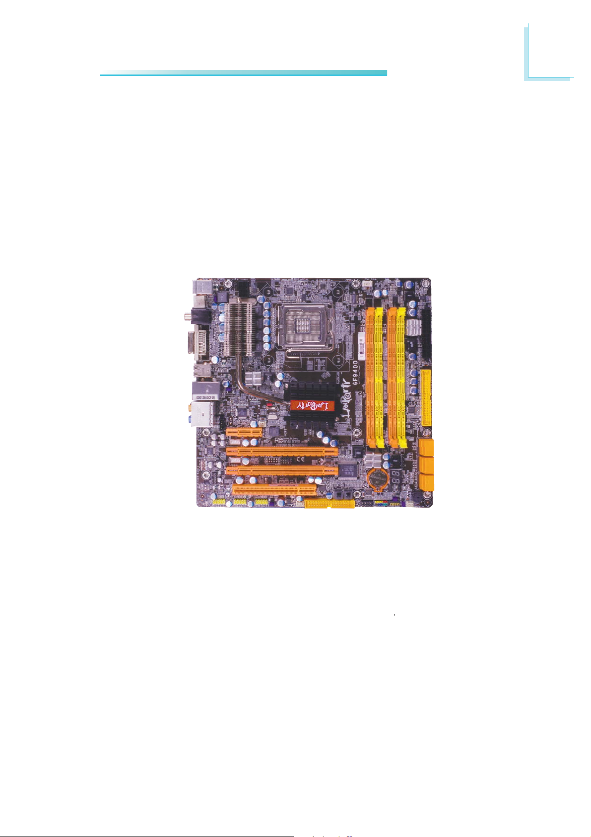
Chapter 2 - Hardware Installation
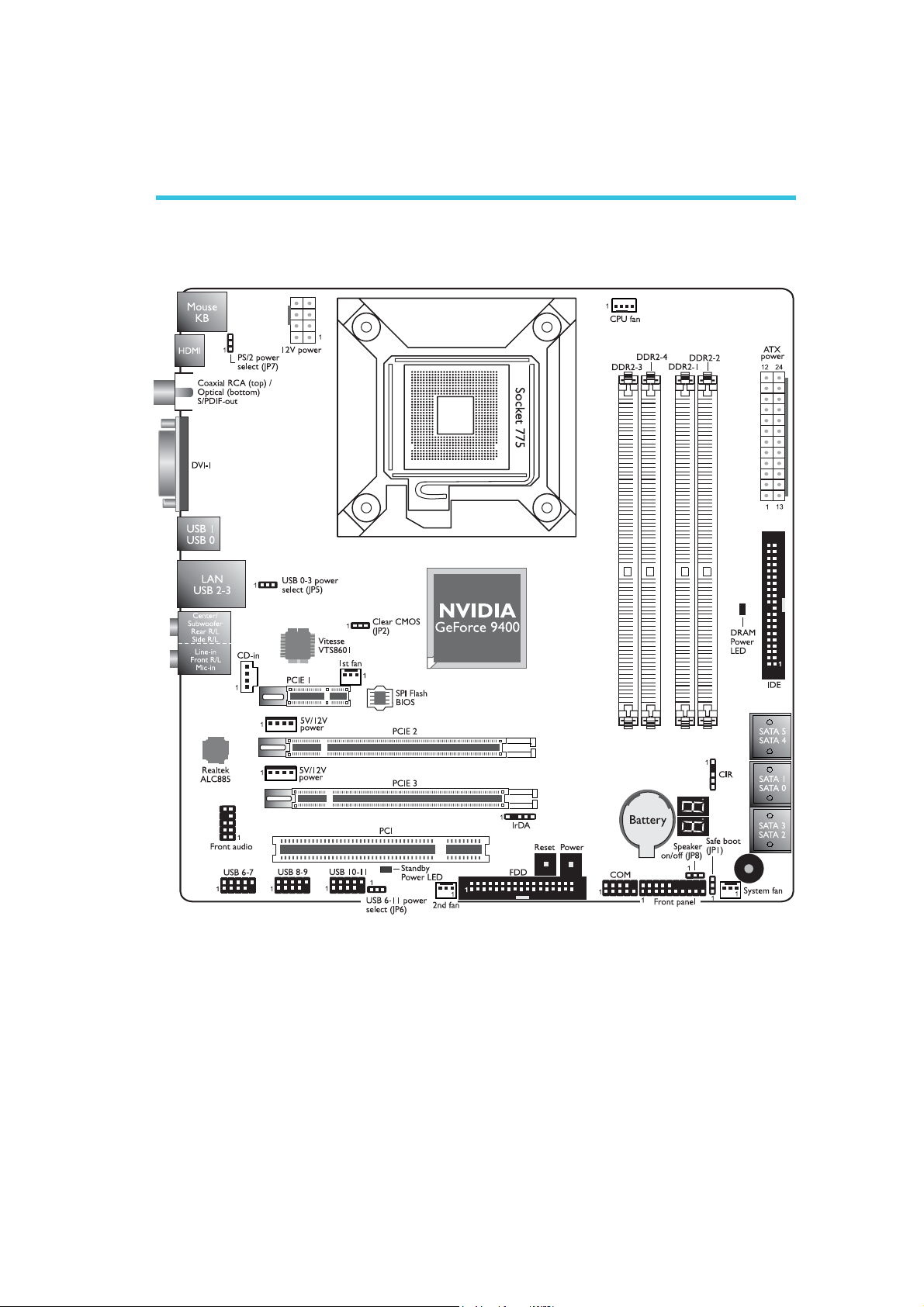
System Board Layout
Hardware Installation
2
15
Page 16
2
.
.
.
.
.
.
.
.
.
.
.
.
.
.
.
.
Hardware Installation
Warning:
Electrostatic discharge (ESD) can damage your system board, processor, disk drives, add-in boards, and other components. Perform the
upgrade instruction procedures described at an ESD workstation only.
If such a station is not available, you can provide some ESD protection by wearing an antistatic wrist strap and attaching it to a metal
part of the system chassis. If a wrist strap is unavailable, establish
and maintain contact with the system chassis throughout any procedures requiring ESD protection.
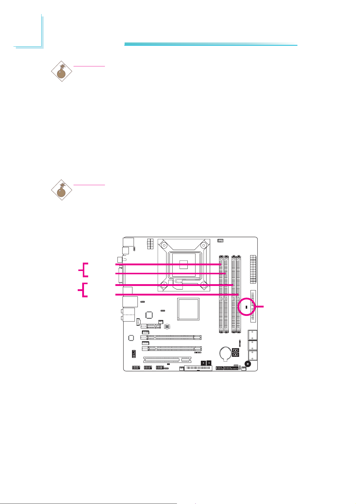
System Memory
Warning:
When the DRAM Power LED lit red, it indicates that power is
present on the DIMM sockets. Power-off the PC then unplug the
power cord prior to installing any memory modules. Failure to do so
will cause severe damage to the motherboard and components.
Channel A
Channel B
The four DIMM sockets on the system board are divided into 2
channels:
DIMM 3
DIMM 4
DIMM 1
DIMM 2
DRAM
Power LED
Channel A - DIMM 3 and DIMM 4
Channel B - DIMM 1 and DIMM 2
16
Page 17

Hardware Installation
The system board supports the following memory interface.
Single Channel (SC)
Data will be accessed in chunks of 64 bits (8B) from the memory
channels.
Virtual Single Channel (VSC)
If both channels are populated with different memory configurations,
the MCH defaults to Virtual Single Channel.
Dual Channel (DC)
Dual channel provides better system performance because it doubles
the data transfer rate.
Dynamic Mode Addressing
This mode minimizes the overhead of opening/closing pages in
memory banks allowing for row switching to be done less often.
2
Single Channel
Virtual Single
Channel
Dual Channel
Dynamic Mode
Addressing
DIMMs are on the same channel.
DIMMs in a channel can be identical or completely different.
Not all slots need to be populated.
DIMMs of different memory configurations
are on different channels.
Odd number of slots can be populated.
DIMMs of the same memory configuration
are on different channels.
In single channel, requires even number or
rows (side of the DIMM) populated. This
mode can be enabled with 1 SS, 2 SS or
2 DS.
In VSC mode, both channels must have
identical row structure.
BIOS Setting
Configure the system memory in the Genie BIOS Setting submenu
of the BIOS. Refer to chapter 3 for more information.
17
Page 18

2
Hardware Installation
The table below lists the various optimal operating modes that should
be configured for the memory channel operation.
Config
No memory
Single channel A
Single channel A
Single channel A
Single channel B
Single channel B
Single channel B
Virtual single channel
Virtual single channel
Virtual single channel
Virtual single channel
Virtual single channel
Virtual single channel
DIMM 1
E
P
P
E
E
E
E
E
E
E
P
P(**)
p(**)
DIMM 2
E
E
P
P
E
E
E
P(**)
P
P(**)
E
E
E
DIMM 3
E
E
E
E
P
P
E
E
P
P
E
P(**)
P(**)
DIMM 4
E
E
E
E
E
P
P
P(**)
E
P(**)
P
E
P
Virtual single channel
Virtual single channel
Virtual single channel
Dual channel
Dual channel
Dual channel
Continued on the next page...
P
P(**)
P(**)
E
P(*)(1,3)
P(*)(1,3)
P(**)
P
P(**)
P(*)(2,4)
E
P(*)(2,4)
E
P(**)
P(**)
E
P(*)(1,3)
P(*)(1,3)
P(**)
E
P(**)
P(*)(2,4)
E
P(*)(2,4)
18
Page 19

Hardware Installation
2
Config
Dynamic Mode Addressing
Dynamic Mode Addressing
Dynamic Mode Addressing
Dynamic Mode Addressing
Dynamic Mode Addressing
Dynamic Mode Addressing
P - denotes populated
E - denotes empty
* - denotes DIMMs are identical
** - denotes DIMMs are not identical
SS - denotes Single Sided DIMM
DS - denotes Double Sided DIMM
1, 2, 3 or 4 - denotes the DDR DIMM slot
DIMM 1
E
P(*)(1,3)
DS
P(*)(1,3)
DS
E
P(*)(1,3)
SS
P(*)(1,3)
SS
DIMM 2
P(*)(2,4)
DS
E
P(*)(2,4)
DS
P(*)(2,4)
SS
E
P(*)(2,4)
SS
DIMM 3
E
P(*)(1,3)
DS
P(*)(1,3)
DS
E
P(*)(1,3)
SS
P(*)(1,3)
SS
DIMM 4
P(*)(2,4)
DS
E
P(*)(2,4)
DS
P(*)(2,4)
SS
E
P(*)(2,4)
SS
19
Page 20
2
Hardware Installation
Installing the Memory Module
Note:
The system board used in the following illustrations may not
resemble the actual board. These illustrations are for reference
only.
1. Make sure the PC and all other peripheral devices connected to
it has been powered down.
2. Disconnect all power cords and cables.
3. Locate the DIMM socket on the system board.
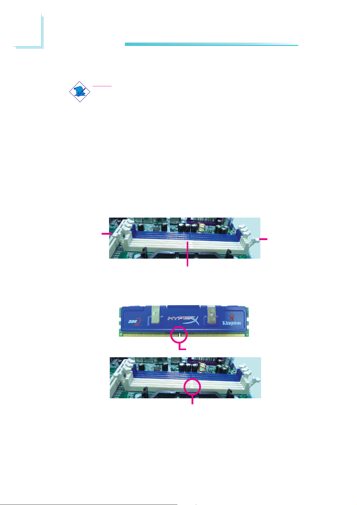
4. Push the “ejector tabs” which are at the ends of the socket to
the side.
Ejector
tab
DIMM sockets
5. Note how the module is keyed to the socket.
Notch
Ejector
tab
20
Key
Page 21
Hardware Installation
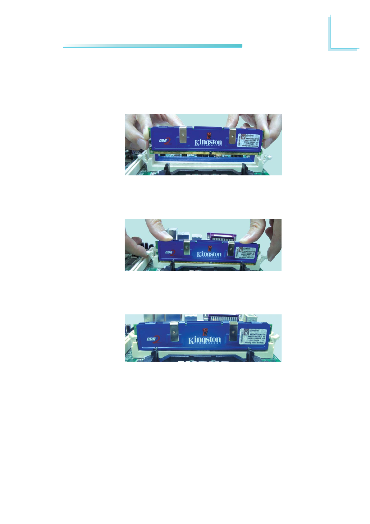
6. Grasping the module by its edges, position the module above
the socket with the “notch” in the module aligned with the “key”
on the socket. The keying mechanism ensures the module can be
plugged into the socket in only one way.
7. Seat the module vertically, pressing it down firmly until it is completely seated in the socket.
2
8. The ejector tabs at the ends of the socket will automatically
snap into the locked position to hold the module in place.
21
Page 22
2
Hardware Installation
CPU
Overview
The system board is equipped with a surface mount LGA 775 socket. This
socket is exclusively designed for installing a LGA 775 packaged Intel
CPU.
Important:
1. Before you proceed, make sure (1) the LGA775 socket1. Before you proceed, make sure (1) the LGA775 socket
1. Before you proceed, make sure (1) the LGA775 socket
1. Before you proceed, make sure (1) the LGA775 socket1. Before you proceed, make sure (1) the LGA775 socket
comes with a protective cap, (2) the cap is not dam-comes with a protective cap, (2) the cap is not dam-
comes with a protective cap, (2) the cap is not dam-
comes with a protective cap, (2) the cap is not dam-comes with a protective cap, (2) the cap is not damaged and (3) the socket’s contact pins are not bent. Ifaged and (3) the socket’s contact pins are not bent. If
aged and (3) the socket’s contact pins are not bent. If
aged and (3) the socket’s contact pins are not bent. Ifaged and (3) the socket’s contact pins are not bent. If
the cap is missing or the cap and/or contact pins arethe cap is missing or the cap and/or contact pins are
the cap is missing or the cap and/or contact pins are
the cap is missing or the cap and/or contact pins arethe cap is missing or the cap and/or contact pins are
damaged,damaged,
damaged,
damaged,damaged,
2. Make sure to keep the protective cap. RMA requests2. Make sure to keep the protective cap. RMA requests
2. Make sure to keep the protective cap. RMA requests
2. Make sure to keep the protective cap. RMA requests2. Make sure to keep the protective cap. RMA requests
will be accepted and processed only if the LGA775will be accepted and processed only if the LGA775
will be accepted and processed only if the LGA775
will be accepted and processed only if the LGA775will be accepted and processed only if the LGA775
socket comes with the protective cap.socket comes with the protective cap.
socket comes with the protective cap.
socket comes with the protective cap.socket comes with the protective cap.
contact your dealer immediately contact your dealer immediately
contact your dealer immediately
contact your dealer immediately contact your dealer immediately
..
.
..
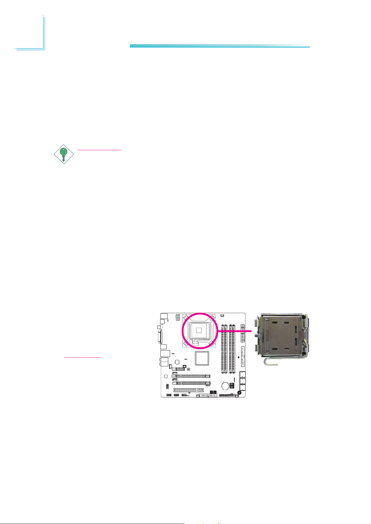
Installing the CPU
1. Make sure the PC and all other peripheral devices connected to it has
been powered down.
2. Disconnect all power cords and cables.
3. Locate the LGA 775
CPU socket on the
system board.
Important:
The CPU socket must
not come in contact with
anything other than the
CPU. Avoid unnecessary
exposure. Remove the
protective cap only when
you are about to install
the CPU.
22
Page 23
Hardware Installation
2
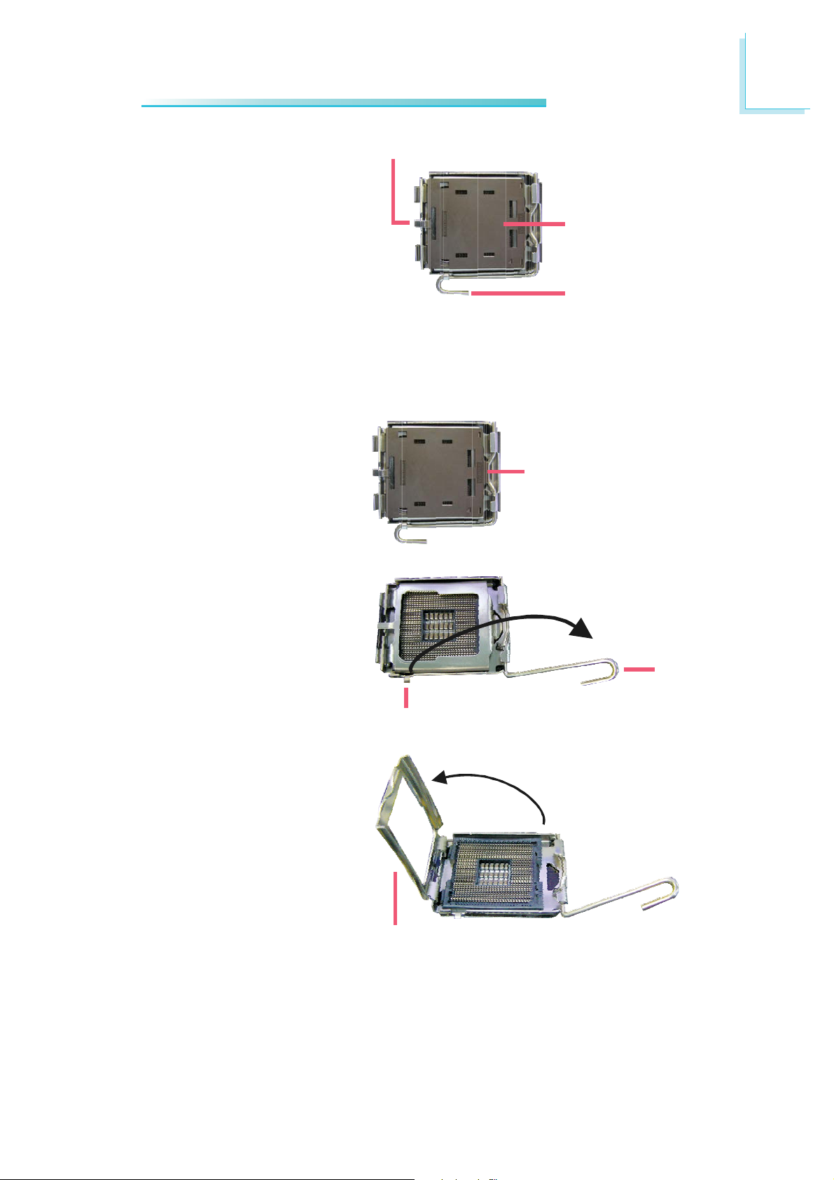
4. The CPU socket comes
with a cover that is
attached with a removable protective cap. The
cap is used to protect
the CPU socket against
dust and harmful par ticles. Remove the protective cap only when you
are about to install the
CPU.
5. Lift the protective cap
from the location
pointed below to detach
the cap from the cover.
Cover
Protective cap
Lever
Lift this part up
6. Unlock the socket by
pushing the lever down,
moving it away from the
side tab of the socket,
then lifting it up.
7. Now lift the cover.
Lever
lifted
Ta b
Cover
23
Page 24
2
Hardware Installation
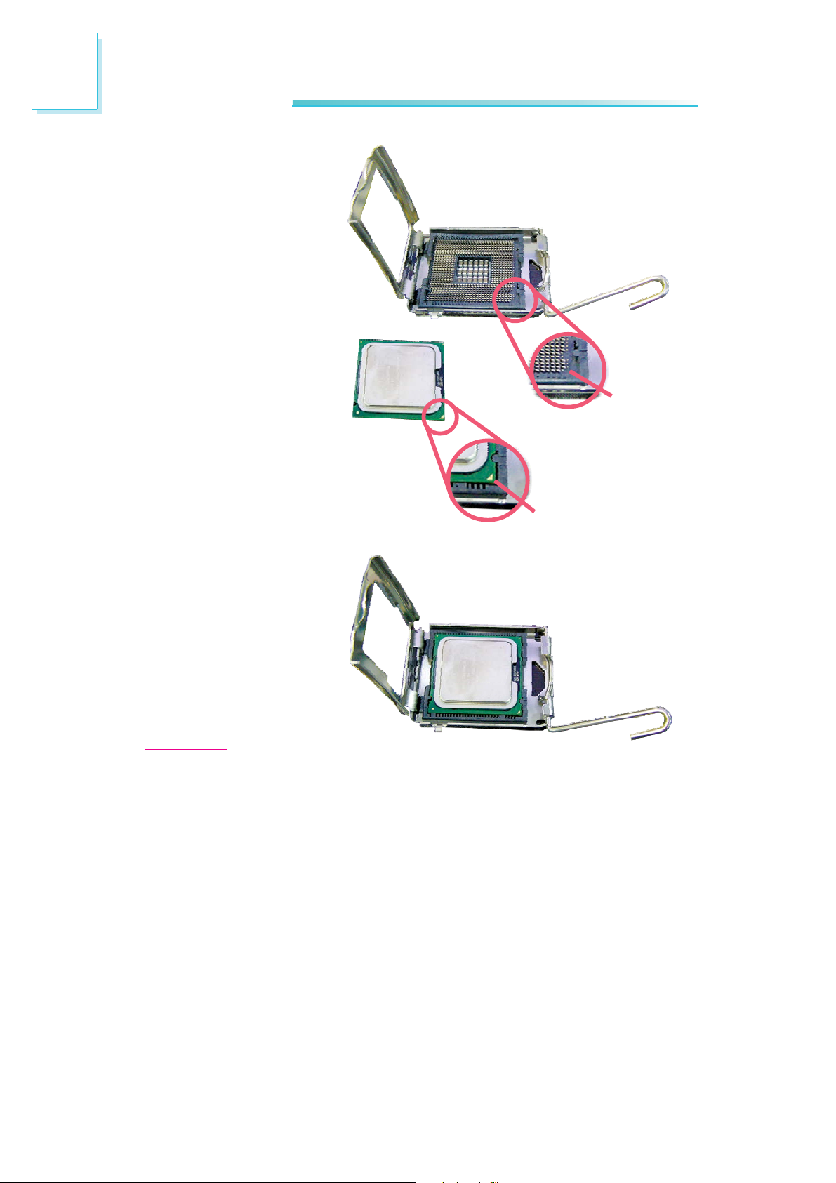
8. Position the CPU above
the socket. The gold
mark on the CPU must
align with pin 1 of the
CPU socket.
Important:
Handle the CPU by its
edges and avoid touching the pins.
Pin 1 of
the socket
9. Insert the CPU into the
socket until it is seated
in place. The CPU will fit
in only one orientation
and can easily be inserted without exerting
any force.
Important:
Do not force the CPU
into the socket. Forcing
the CPU into the socket
may bend the pins and
damage the CPU.
Gold mark
24
Page 25
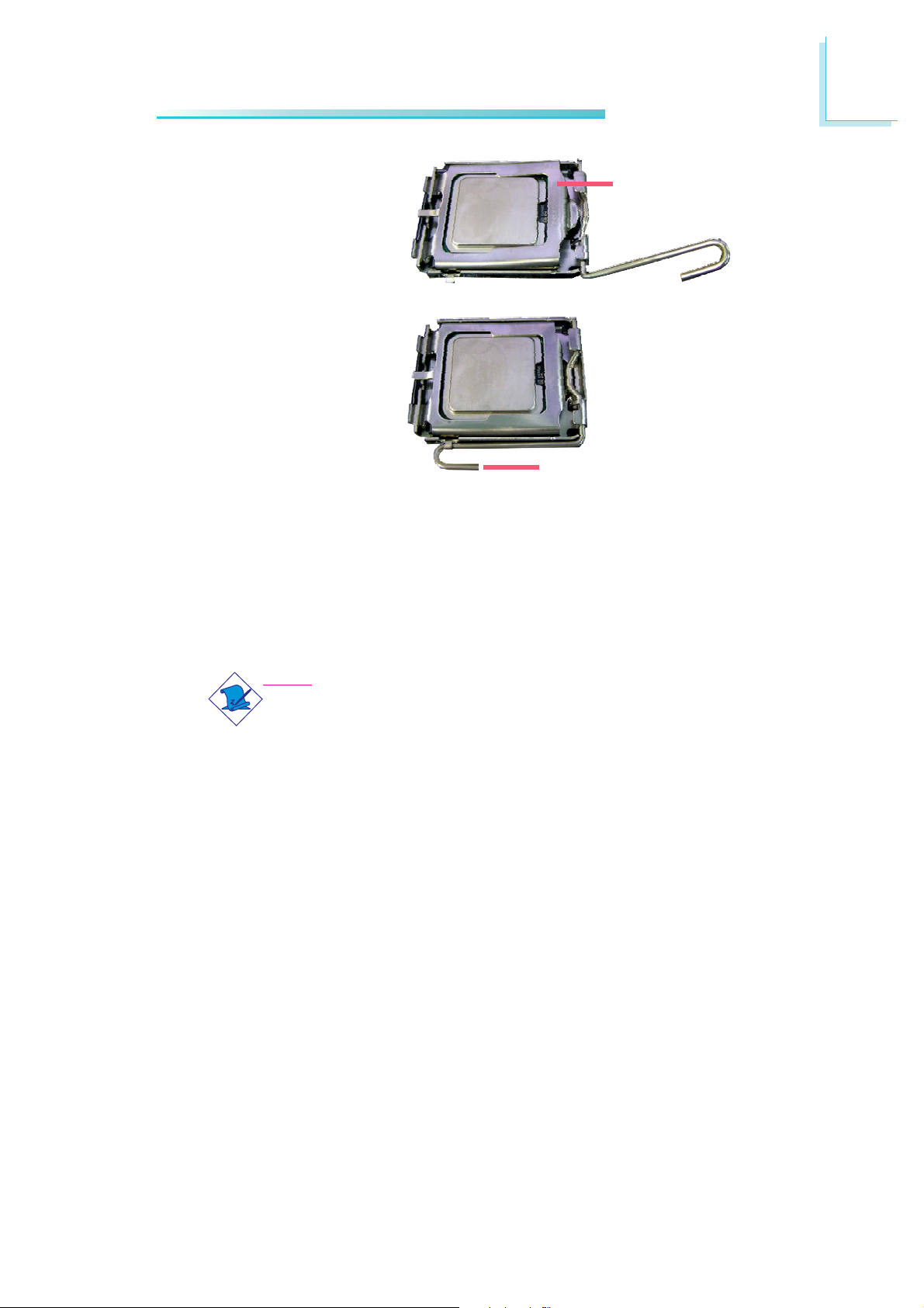
10. Once the CPU is in
place, move the cover
down.
11. Push the lever down to
lock the socket. The
lever should hook onto
the side tab to indicate
that the CPU is completely secured in the
socket.
Installing the Fan and Heat Sink
Hardware Installation
2
Cover
Lever
The CPU must be kept cool by using a CPU fan with heat sink.
Without sufficient air circulation across the CPU and heat sink, the
CPU will overheat damaging both the CPU and system board.
Note:
• Use only certified fan and heat sink.
• The fan and heat sink package usually contains the fan and
heat sink assembly, and an installation guide. If the installation procedure in the installation guide differs from the one
in this section, please follow the installation guide in the
package.
1. Before you install the fan / heat sink, you must apply a thermal
paste onto the top of the CPU. The thermal paste is usually
supplied when you purchase the CPU or fan heat sink assembly.
Do not spread the paste all over the surface. When you later
place the heat sink on top of the CPU, the compound will disperse evenly.
Do not apply the paste if the fan / heat sink already has a patch
of thermal paste on its underside. Peel the strip that covers the
paste before you place the fan / heat sink on top of the CPU.
25
Page 26
2
Hardware Installation
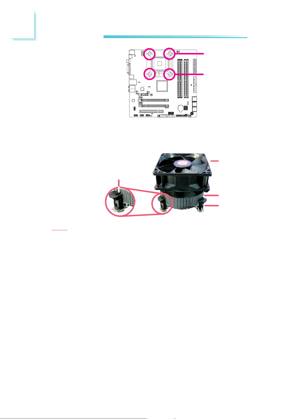
2. Place the heat sink on
top of the CPU. The 4
studs around the heat
sink which are used to
secure the heat sink
onto the system board
must match the 4
mounting holes around
the socket.
Position each stud so
that the groove faces
the heat sink then push
it down firmly until it
clicks into place.
Groove
Mounting hole
Mounting hole
Fan
Heat sink
Stud
Note:
You will not be able to secure the fan and heat sink assembly in place
if the groove is not facing the heat sink.
3. Connect the CPU fan’s cable connector to the CPU fan connector on
the system board.
26
Page 27
Chipset Heat Sink
The chipset must be kept cool by using a heat sink. The heat sink
will dissipate heat generated by the chipset. Without the heat sink,
the chipset will overheat damaging both the chipset and the system
board.
The system board comes with the heat sink already installed on the
board. The copper-made heat pipe technology provides excellent
heat dissipation.
Hardware Installation
2
27
Page 28
2
Hardware Installation
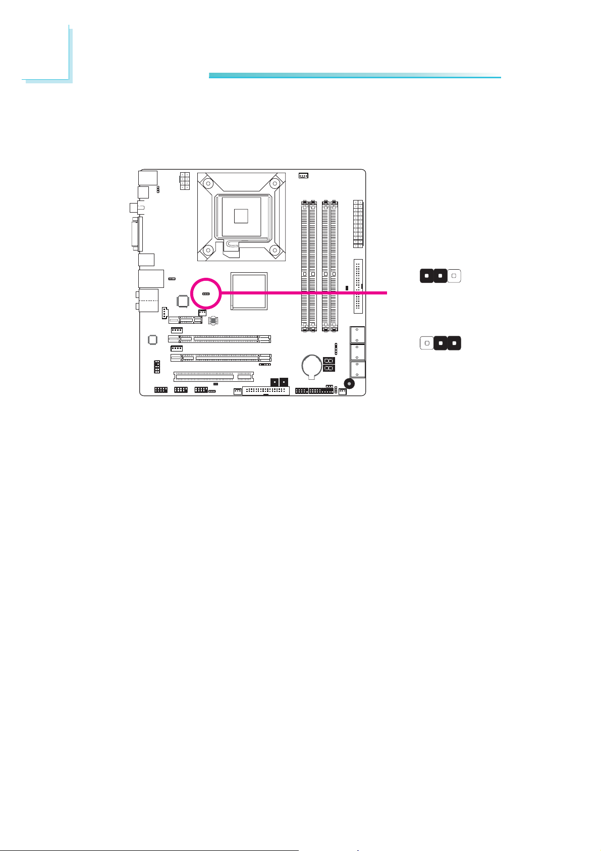
Jumper Settings
Clear CMOS Data
JP2
1-2 On: Normal
X
312
(default)
312
2-3 On:
Clear CMOS Data
If you encounter the following,
a) CMOS data becomes corrupted.
b) You forgot the supervisor or user password.
c) The overclocked settings in the BIOS resulted to the system’s in-
stability or caused system boot up problems.
you can reconfigure the system with the default values stored in the
ROM BIOS.
To load the default values stored in the ROM BIOS, please follow
the steps below.
1. Power-off the system then unplug the power cord.
2. Set JP2 pins 2 and 3 to On. Wait for a few seconds and set JP2
back to its default setting, pins 1 and 2 On.
28
3. Now plug the power cord then power-on the system.
Page 29
PS/2 Power Select
Hardware Installation
2
JP7
X
1-2 On: 5V
Important:
The 5VSB power source of
your power supply must
support ≥720mA.
3
2
1
2-3 On: 5VSB
(default)
3
2
1
Selecting 5VSB will allow you to use the PS/2 keyboard or PS/2
mouse to wake up the system.
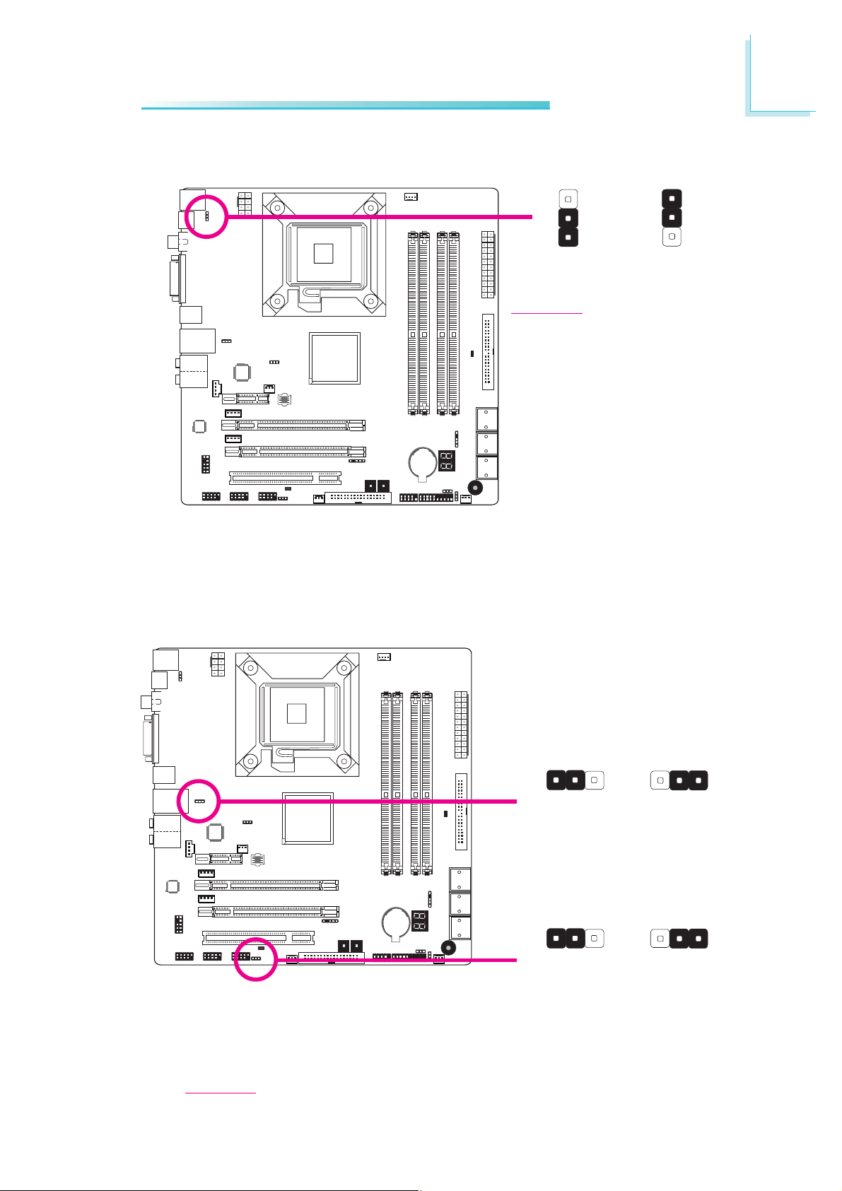
USB Power Select
Selecting 5VSB will allow you to use the USB keyboard or USB
mouse to wake up the system.
USB 0-3
(JP5)
X
USB 6-11
(JP6)
X
312 312
(default)
312 312
1-2 On: 5V
(default)
2-3 On: 5VSB1-2 On: 5V
2-3 On: 5VSB
Important:
The 5VSB power source of your power supply must support ≥1.5A (2 devices)
or ≥2A (3 or more devices).
29
Page 30
2
Hardware Installation
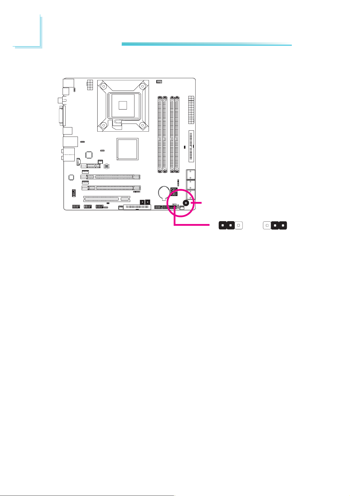
Speaker On/Off Select
Buzzer
JP8
312 312
X
1-2 On:
Speaker Off
The system board is equipped with a buzzer which serves as the
PC’s speaker. By default the buzzer is “on” allowing you to hear the
system’s beep messages and warnings. If you intend to use an external speaker, turn this function off by setting JP8 pins 1 and 2 to On.
2-3 On:
Speaker On
(default)
30
Page 31

Safe Boot
Hardware Installation
2
3
2
1
2-3 On:
Default
JP1
X
3
2
1
1-2 On:
Safe boot
This jumper is used to safely reboot the system whenever the system hangs and you are unable to restart the system.
1. Power-off the system then unplug the power cord.
2. Set pins 1 and 2 to On. Wait for a few seconds then set the
jumper back to its default setting, pins 2 and 3 On.
3. Plug the power cord then power-on the system. The system will
reboot normally without losing all data stored in the CMOS.
31
Page 32

2
Hardware Installation
Rear Panel I/O Ports
PS/2
Mouse
PS/2 K/B Optical
HDMI
PS/2 Ports and S/PDIF Ports
PS/2 Mouse
PS/2 KB
Coaxial
S/PDIF-out
DVI-I
S/PDIF-out
W
USB 1
USB 0
Center/
Subwoofer
LAN
USB 2-3
Rear R/L
Line-in
Front R/L
Mic-in
Side R/L
W
Coaxial RCA
S/PDIF
Optical S/PDIF
PS/2 Mouse and PS/2 Keyboard Ports
These ports are used to connect a PS/2 mouse and a PS/2 keyboard.
Optical S/PDIF
The optical S/PDIF jack is used to connect an external audio output
device using an optical S/PDIF cable.
Coaxial RCA S/PDIF
The coaxial RCA S/PDIF jack is used to connect an external audio
output device using a coaxial S/PDIF cable.
32
Important:
DO NOT use optical S/PDIF and Coaxial RCA S/PDIF at the
same time.
Page 33

HDMI and DVI-I Ports
HDMI
DVI-I
Hardware Installation
2
W
W
HDMI
The HDMI port which carries both digital audio and video signals is
used to connect a LCD monitor or digital TV that has the HDMI
port.
DVI-I
The DVI-I port is used to connect a digital LCD monitor or LCD
TV.
33
Page 34

2
Hardware Installation
USB and LAN Ports
USB 1
USB 0
W
LAN
USB 3
W
USB 2
-Data
+Data
-Data
+Data
GND
N. C.
10
Key
GND
W
9
USB 6-7
USB 10-11
USB 8-9
VCC
2
1
VCC
USB
The USB ports are used to connect USB 2.0/1.1 devices. The 10-pin
connectors allow you to connect 6 additional USB 2.0/1.1 ports.
Your USB ports may come mounted on a card-edge bracket. Install
the card-edge bracket to an available slot at the rear of the system
chassis then connect the USB port cables to these connectors.
34
LAN
The LAN port allows the system board to connect to a local area
network by means of a network hub.
Page 35

Audio and CD-In
Hardware Installation
2
Center/
Subwoofer
Rear R/L
Side R/L
AuD_L_Return
Key
AuD_R_Return
AuD_Vcc
GND
Rear audio
9
10
12
Front audio
Line-in
Front R/L
Mic-in
W
AuD_L_Out
N. C.
AuD_R_Out
Mic Power
Mic
W
Right audio channel
Left audio channel
Ground
Ground
W
4
CD-in
1
Rear Panel Audio
Center/Subwoofer Jack (Orange)
This jack is used to connect to the center and subwoofer speakers of the audio system.
Rear Right/Left Jack (Black)
This jack is used to connect to the rear right and rear left speakers of the audio system.
Side Right/Left Jack (Gray)
This jack is used to connect to the side left and side right speakers of the audio system.
Line-in (Light Blue)
This jack is used to connect any audio devices such as Hi-fi set,
CD player, tape player, AM/FM radio tuner, synthesizer, etc.
35
Page 36

2
Hardware Installation
Line-out - Front Right/Left Jack (Lime)
This jack is used to connect to the front right and front left
speakers of the audio system.
Mic-in Jack (Pink)
This jack is used to connect an external microphone.
Front Audio
The front audio connector is used to connect to the line-out and
mic-in jacks that are at the front panel of your system.
CD-in
The CD-in connector is used to receive audio from a CD-ROM
drive, TV tuner or MPEG card.
Internal I/O Connectors
Serial ATA Connectors
SATA 4-5
SATA 0-1
SATA 2-3
36
The Serial ATA (SATA) connectors are used to connect Serial ATA
drives. Connect one end of the Serial ATA cable to a Serial ATA
connector and the other end to your Serial ATA device.
Configuring RAID
Refer to the RAID chapter in this manual for more information
about creating RAID on Serial ATA drives.
Page 37

FDD Connector and IDE Connector
Hardware Installation
2
FDD Connector
40
39
X
21
IDE
2
X
133
FDD
34
The floppy disk drive connector is used to connect a floppy drive.
Insert one end of the floppy cable into this connector and the other
end-most connector to the floppy drive. The colored edge of the
cable should align with pin 1 of this connector.
IDE Connector
The IDE disk drive connector is used to connect 2 IDE disk drives.
An IDE cable have 3 connectors on them, one that plugs into this
connector and the other 2 connects to IDE devices. The connector
at the end of the cable is for the Master drive and the connector in
the middle of the cable is for the Slave drive. The colored edge of
the cable should align with pin 1 of this connector.
Note:
When using two IDE drives, one must be set as the master
and the other as the slave. Follow the instructions provided by
the drive manufacturer for setting the jumpers and/or switches
on the drives.
37
Page 38

2
Hardware Installation
IrDA,CIR and Serial (COM) Connectors
9
5VSB
N. C.
CIRRX
Ground
CIRTX
COM
IRRX
N. C.
Ground
VCC
IRTX
X
15
IrDA
X
1
X
5
CIR
DSR
DTR
TD
GND
CTS
RI
RTS
RD
2
1
CD
IrDA and CIR
Connect the cable connector from your IrDA module to the IrDA
connector or CIR connector.
Note:
The sequence of the pin functions on some IrDA/CIR cable
may be reversed from the pin function defined on the system
board. Make sure to connect the cable connector to the IrDA/
CIR connector according to their pin functions.
38
You may need to install the proper drivers in your operating system
to use the IrDA/CIR function. Refer to your operating system’s
manual or documentation for more information.
Serial (COM)
The serial (COM) connector is used to connect modems, serial printers, remote display terminals, or other serial devices. Your COM port
may come mounted on a card-edge bracket. Install the card-edge
Page 39

bracket to an available slot at the rear of the system chassis then
connect the serial port cable to this connector. The colored edge of
the cable should align with pin 1 of this connector.
Cooling Fan Connectors
Hardware Installation
Sense
Power
X
Ground
Speed
Control
41
CPU fan
2
3
Sense
Power
1st Fan
3
Sense
Power
2nd Fan
1
Ground
X
1
Ground
X
3
Sense
System fan
X
Power
These fan connectors are used to connect cooling fans. Cooling fans
will provide adequate airflow throughout the chassis to prevent overheating the CPU and system board components.
1
Ground
39
Page 40

2
Hardware Installation
EZ Touch Switches
X
Reset Power
The presence of the power switch and reset switch on the system
board are user-friendly especially to DIY users. They provide convenience in powering on and/or resetting the system while fine tuning
the system board before it is installed into the system chassis.
40
Page 41

LEDs
.
.
.
.
.
.
.
.
Hardware Installation
2
DRAM
Power LED
Diagnostic
LED
Standby Power LED
DRAM Power LED
This LED will light when the system’s power is on.
Standby Power LED
This LED will light when the system is in the standby mode.
Diagnostic LED
The Diagnostic LED displays POST codes. POST (Power-On Self
Tests) which is controlled by the BIOS is performed whenever you
power-on the system. POST will detect the status of the system and
its components. Each code displayed on the LED corresponds to a
certain system status.
Warning:
When the DRAM Power LED and/or Standby Power LED lit red,
it indicates that power is present on the DIMM sockets and/or
PCI slots. Power-off the PC then unplug the power cord prior to
installing any memory modules or add-in cards. Failure to do so
will cause severe damage to the motherboard and components.
41
Page 42

2
Hardware Installation
Power Connectors
Use a power supply that complies with the ATX12V Power Supply
Design Guide Version 1.1. An ATX12V power supply unit has a
standard 24-pin ATX main power connector that must be inserted
into this connector.
+3.3VDC
+12VDC
+12VDC
X
+5VSB
PWR_OK
+5VDC
+5VDC
+3.3VDC
+3.3VDC
COM
COM
COM
12 24
COM
+5VDC
+5VDC
+5VDC
NC
COM
COM
COM
PS_ON#
COM
-12VDC
+3.3VDC
131
Your power supply unit may come with an 8-pin or 4-pin +12V
power connector. The +12V power enables the delivery of more
+12VDC current to the processor’s Voltage Regulator Module
(VRM). If available, it is preferable to use the 8-pin power; otherwise
connect a 4-pin power to this connector.
X
+12V
8
5
4
Ground
1
42
Page 43

Hardware Installation
The power connectors from the power supply unit are designed to
fit the 24-pin and 8-pin connectors in only one orientation. Make
sure to find the proper orientation before plugging the connectors.
A FDD-type power connector provides auxiliary power to a
graphics card. We recommend that you plug a power cable from the
power supply unit to the 5V/12V power connector. This will provide
more stability to the entire system. The system board will still work
even if the additional power connector is not connected.
2
1
+5V
Ground
Ground
The system board requires a minimum of 300 Watt power supply
to operate. Your system configuration (CPU power, amount of
memory, add-in cards, peripherals, etc.) may exceed the minimum
power requirement. To ensure that adequate power is provided, we
strongly recommend that you use a minimum of 400 Watt (or
greater) power supply.
Important:
Insufficient power supplied to the system may result in instability or the add-in boards and peripherals not functioning properly. Calculating the system’s approximate power usage is important to ensure that the power supply meets the system’s
consumption requirements.
4
+12V
43
Page 44

2
Hardware Installation
Restarting the PC
Normally, you can power-off the PC by:
1. Pressing the power button at the front panel of the chassis.
or
2. Pressing the power switch that is on the system board (note: not
all system boards come with this switch).
If for some reasons you need to totally cut off the power supplied
to the PC, switch off the power supply or unplug the power cord.
Take note though that if you intend to restart it at once, please
strictly follow the steps below.
1. The time where power is totally discharged varies among power
supplies. It's discharge time is highly dependent on the system's
configuration such as the wattage of the power supply, the sequence of the supplied power as well as the number of peripheral devices connected to the system. Due to this reason, we
strongly recommend that you wait for the Standby Power LED
(refer to the “LEDs” section in this chapter for the location of the
Standby Power LED) to lit off.
2. After the Standby Power LED has lit off, wait for 6 seconds
before powering on the PC.
If the system board is already enclosed in a chassis which apparently will not make the Standby Power LED visible, wait for 15
seconds before you restore power connections. 15 seconds is
approximately the time that will take the LED to lit off and the
time needed before restoring power.
The above will ensure protection and prevent damage to the
motherboard and components.
44
Page 45

Front Panel Connectors
Hardware Installation
2
ATX-SW
PWR-LED
2
X
1
HD-LED
RESET
HD-LED: Primary/Secondary IDE LED
This LED will light when the hard drive is being accessed.
RESET: Reset Switch
This switch allows you to reboot without having to power off the
system thus prolonging the life of the power supply or system.
SPEAKER: Speaker Connector
This connects to the speaker installed in the system chassis.
ATX-SW: ATX Power Switch
Depending on the setting in the BIOS setup, this switch is a “dual
function power button” that will allow your system to enter the SoftOff or Suspend mode.
SPEAKER
20
19
45
Page 46

2
Hardware Installation
PWR-LED: Power/Standby LED
When the system’s power is on, this LED will light. When the system
is in the S1 (POS - Power On Suspend) or S3 (STR - Suspend To
RAM) state, it will blink every second.
Note:
If a system did not boot-up and the Power/Standby LED did
not light after it was powered-on, it may indicate that the CPU
or memory module was not installed properly. Please make
sure they are properly inserted into their corresponding socket.
HD-LED
(Primary/Secondary IDE LED)
Reserved
ATX-SW
(ATX power switch)
Reserved
RESET
(Reset switch)
SPEAKER
(Speaker connector)
PWR-LED
(Power/Standby LED)
Pin
Pin Assignment
3
HDD LED Power
5
HDD
14
N. C.
16
N. C.
8
PWRBT+
10
PWRBT-
18
N. C.
20
N. C.
7
Ground
9
H/W Reset
13
Speaker Data
15
N. C.
17
Ground
19
Speaker Power
2
LED Power (+)
4
LED Power (+)
6
LED Power (-) or Standby Signal
46
Page 47

Expansion Slots
PCI Express x1
PCI Express x16
PCI Express x16
Hardware Installation
2
PCI
47
Page 48

2
Hardware Installation
Smart Connectors
The Smart Connectors (USB, IEEE 1394 and Front Panel) serve as
extended connectors allowing you to easily connect cables to the
connectors that are on the system board. This is specially advantageous
when using the front panel connectors as this will prevent wrong cable
connection.
USB 1394 Front Panel
Front Panel Connectors
1. Connect all front panel cables
from the chassis to the front
panel smart connector. Connect
according to the pin definition
shown on the smart connector.
2. Connect the front panel smart
connector to the front panel
connector on the system board.
USB and IEEE 1394 Connectors
1. Connect your USB/1394 port cable to the USB/1394 smart connector.
Connect according to the pin definition shown on the smart connector.
48
2. Connect the USB/1394 smart connector to the respective connectors
on the system board.
Page 49

Chapter 3 - BIOS Setup
Switchable Modes for Overclocking
Aimed to provide convenience and superb overclockability, the Genie
BIOS Setting submenu comes available in Easy mode (default mode)
and Advance mode.
Easy Mode
Easy mode displays fields commonly used by users.
Advance Mode
If you intend to tweak your PC or boost its overclock feature, you
can switch the Genie BIOS Setting submenu from Easy mode to
Advance mode by simply pressing <F9> in the main menu of the
Award BIOS utility then pressing <Y> to select Advance Mode. The
Advance mode will display a wide range of fields useful in
overclocking the board.
3
BIOS Setup
X Standard CMOS Features
X Advanced BIOS Features
X Advanced Chipset Features
X Integrated Peripherals
X Power Management Setup
X PnP/PCI Configurations
X PC Health Status
Esc : Quit
F10 : Save & Exit Setup
Phoenix - AwardBIOS CMOS Setup Utility
X Genie BIOS Setting
X CMOS Reloaded
Load Optimized Defaults
Set Supervisor Password
Y:Advance Mode; N:Easy Mode (Y/N)? Y
Time, Date, Hard Disk Type...
Set User Password
Save & Exit Setup
Exit Without Saving
↑ ↓ → ← : Select Item
49
Page 50

3
BIOS Setup
Award BIOS Setup Utility
The Basic Input/Output System (BIOS) is a program that takes care
of the basic level of communication between the processor and peripherals. In addition, the BIOS also contains codes for various advanced features found in this system board. This chapter explains the
Setup Utility for the Award BIOS.
After you power up the system, the BIOS message appears on the
screen and the memory count begins. After the memory test, the
following message will appear on the screen:
Press DEL to enter setup
If the message disappears before you respond, restart the system or
press the “Reset” button. You may also restart the system by pressing the <Ctrl> <Alt> and <Del> keys simultaneously.
When you press <Del>, the main menu screen will appear.
Phoenix - AwardBIOS CMOS Setup Utility
X Standard CMOS Features
X Advanced BIOS Features
X Advanced Chipset Features
X Integrated Peripherals
X Power Management Setup
X PnP/PCI Configurations
X PC Health Status
Esc : Quit
F10 : Save & Exit Setup
Time, Date, Hard Disk Type...
X Genie BIOS Setting
X CMOS Reloaded
Load Optimized Defaults
Set Supervisor Password
Set User Password
Save & Exit Setup
Exit Without Saving
↑ ↓ → ← : Select Item
50
Page 51

Standard CMOS Features
Use the arrow keys to highlight “Standard CMOS Features” then
press <Enter>. A screen similar to the one below will appear.
3
BIOS Setup
Phoenix - AwardBIOS CMOS Setup Utility
Date <mm:dd:yy>
Time <hh:mm:ss>
X Primary IDE Master
X Primary IDE Slave
X Secondary IDE Master
X Secondary IDE Slave
X Internal Phy SATA 1
X Internal Phy SATA 3
X Internal Phy SATA 2
X Internal Phy SATA 4
Drive A
Halt On
Base Memory
Extended Memory
Total Memory
↑↓→←: Move Enter: Select F1: General Help+/-/PU/PD: Value F10: Save ESC: Exi t
F5: Previous Values F6: Fail-Safe Defaults F7: Optimized Defaults
Standard CMOS Features
Wed, Feb 4 2009
20 : 20 : 30
None
None
None
None
WDC WD1600AAJS-00B4A
PIONEER DVD-ROM DVDNone
None
1.44M, 3.5 in.
All, But keyboard
640K
2096128K
2097152K
Item Help
Menu Level
Change the day, month,
year and century
X
The settings on the screen are for reference only. Your version may not be
identical to this one.
Date
Time
The date format is <day>, <month>, <date>, <year>. Day displays
a day, from Sunday to Saturday. Month displays the month, from
January to December. Date displays the date, from 1 to 31. Year
displays the year, from 1994 to 2079.
The time format is <hour>, <minute>, <second>. The time is based
on the 24-hour military-time clock. For example, 1 p.m. is 13:00:00.
Hour displays hours from 00 to 23. Minute displays minutes from
00 to 59. Second displays seconds from 00 to 59.
51
Page 52

3
BIOS Setup
Primary IDE Master to Internal Phy SATA 4
Primary IDE Master/Slave
Used to configure Parallel ATA drives
Secondary IDE Master/Slave
Internal Phy SATA 1
Internal Phy SATA 3
Used to configure Serial ATA drives
Internal Phy SATA 2
Internal Phy SATA 4
Note:
The fields for configuring Serial ATA drives will appear only if the
Serial ATA function is Enabled. Enable this function in the Integrated Peripherals submenu of the BIOS.
Primary IDE Master to Secondary IDE Slave
To configure IDE drives, move the cursor to a field then press
<Enter>. The following screen will appear.
Phoenix - AwardBIOS CMOS Setup Utility
IDE HDD Auto-Detection
Primary IDE Master
Access Mode
Capacity
Cylinder
Head
Precomp
Landing Zone
Sector
Primary IDE Master
Press Enter
Auto
Auto
0 MB
0
0
0
0
0
Item Help
Menu Level
To auto-detect the
HDD’s size, head... on
this channel
XX
52
↑↓→←: Move Enter: Select F1: General Help+/-/PU/PD: Value F10: Save ESC: Exit
F5: Previous Values F6: Fail-Safe Defaults F7: Optimized Defaults
The settings on the screen are for reference only. Your version may not be
identical to this one.
IDE HDD Auto-Detection
Detects the parameters of the drive. The parameters will automatically be shown on the screen.
Page 53

BIOS Setup
Primary IDE Master to Secondary IDE Slave
The drive type information should be included in the documentation
from your hard disk vendor. If you select ”Auto”, the BIOS will autodetect the HDD & CD-ROM drive at the POST stage and show
the IDE for the HDD & CD-ROM drive. If a hard disk has not
been installed, select “None”.
Access Mode
For hard drives larger than 528MB, you would typically select the
LBA type. Cer tain operating systems require that you select CHS or
Large. Please check your operating system’s manual or Help desk on
which one to select.
Capacity
3
Displays the approximate capacity of the disk drive. Usually the size
is slightly greater than the size of a formatted disk given by a disk
checking program.
Cylinder
This field displays the number of cylinders.
Head
This field displays the number of read/write heads.
Precomp
This field displays the number of cylinders at which to change the
write timing.
Landing Zone
This field displays the number of cylinders specified as the landing
zone for the read/write heads.
Sector
This field displays the number sectors per track.
53
Page 54

3
BIOS Setup
Internal Phy SATA 1 to Internal Phy SATA 4
Move the cursor to a field then press <Enter>. The following screen
will appear.
The settings on the screen are for reference only. Your version may not be
identical to this one.
Drive A
This field identifies the type of floppy disk drive installed.
Phoenix - AwardBIOS CMOS Setup Utility
IDE Auto-Detection
Extended IDE Drive
Access Mode
Capacity
Cylinder
Head
Precomp
Landing Zone
Sector
↑↓→←: Move Enter: Select F1: General Help+/-/PU/PD: Value F10: Save ESC: Exit
F5: Previous Values F6: Fail-Safe Defaults F7: Optimized Defaults
Internal Phy SATA 1
Press Enter
Auto
Auto
0 MB
0
0
0
0
0
Item Help
Menu Level
To auto-detect the
HDD’s size, head... on
this channel
XX
None No floppy drive is installed
360K, 5.25 in. 5-1/4 in. standard drive; 360KB capacity
1.2M, 5.25 in. 5-1/4 in. AT-type high-density drive; 1.2MB capacity
720K, 3.5 in. 3-1/2 in. double-sided drive; 720KB capacity
1.44M, 3.5 in. 3-1/2 in. double-sided drive; 1.44MB capacity
2.88M, 3.5 in. 3-1/2 in. double-sided drive; 2.88MB capacity
54
Page 55

Halt On
This field determines whether the system will stop if an error is
detected during power up. The default setting is All Errors.
3
BIOS Setup
No Errors The system boot will not stop for any errors
detected.
All Errors The system boot will stop whenever the
BIOS detects a non-fatal error.
All, But Keyboard The system boot will not stop for a key-
board error; it will stop for all other errors.
All, But Diskette The system boot will not stop for a disk er-
ror; it will stop for all other errors.
All, But Disk/Key The system boot will not stop for a disk or
keyboard error; it will stop for all other errors.
Base Memory
Displays the amount of base (or conventional) memory installed in
the system. The value of the base memory is typically 512K for
systems with 512K memory installed on the motherboard or 640K
for systems with 640K or more memory installed on the
motherboard.
Extended Memory
Displays the amount of extended memory detected during boot-up.
Total Memory
Displays the total memory available in the system.
55
Page 56

3
BIOS Setup
Advanced BIOS Features
The Advanced BIOS Features allows you to configure your system
for basic operation. Some entries are defaults required by the system
board, while others, if enabled, will improve the performance of your
system or let you set some features according to your preference.
Phoenix - AwardBIOS CMOS Setup Utility
X Removable Device Priority
X Hard Disk Boot Priority
Virus Warning
CPU L3 Cache
Quick Power On Self Test
First Boot Device
Second Boot Device
Third Boot Device
Boot Other Device
Boot Up Floppy Seek
Boot Up Numlock Status
Security Option
MPS Version Control For OS
OS Select For DRAM > 64MB
HDD S.M.A.R.T Capability
Delay For HDD (Secs)
Full Screen LOGO Show
Advanced BIOS Features
Press Enter
Press Enter
Disabled
Enabled
Enabled
CDROM
Removable
Hard Disk
Enabled
Disabled
On
Setup
1.4
Non-OS2
Disabled
0
Disabled
Item Help
Menu Level
Select Hard Disk Boot
Device Priority
X
↑↓→←: Move Enter: Select F1: General Help+/-/PU/PD: Value F10: Save ESC: Exit
F5: Previous Values F6: Fail-Safe Defaults F7: Optimized Defaults
The settings on the screen are for reference only. Your version may not be
identical to this one.
56
Page 57

Removable Device Priority
This field is used to select the boot sequence of the removable
devices. Move the cursor to this field then press <Enter>. Use the
Up or Down arrow keys to select a device then press <+> to
move it up or <-> to move it down the list.
1. Floppy Disks
Phoenix - AwardBIOS CMOS Setup Utility
Removable Device Priority
BIOS Setup
Item Help
Menu Level
Use <↑> or <↓> to
select a device, then
press <+> to move it up,
or <-> to move it down
the list. Press <ESC> to
exit this menu.
XX
3
↑↓: Move PU/PD/+/-: Change Priority F10: Save ESC: Exit
F5: Previous Values F6: Fail-Safe Defaults F7: Optimized Defaults
The settings on the screen are for reference only. Your version may not be
identical to this one.
57
Page 58

3
BIOS Setup
Hard Disk Boot Priority
This field is used to select the boot sequence of the hard drives.
Move the cursor to this field then press <Enter>. Use the Up or
Down arrow keys to select a device then press <+> to move it up
or <-> to move it down the list.
1. Bootable Add-in Cards
↑↓: Move PU/PD/+/-: Change Priority F10: Save ESC: Exit
F5: Previous Values F6: Fail-Safe Defaults F7: Optimized Defaults
The settings on the screen are for reference only. Your version may not be
identical to this one.
Virus Warning
This field protects the boot sector and partition table of your hard
disk drive. When this field is enabled, the Award BIOS will monitor
the boot sector and partition table of the hard disk drive. If an
attempt is made to write to the boot sector or partition table of
the hard disk drive, the BIOS will halt the system and an error
message will appear.
Phoenix - AwardBIOS CMOS Setup Utility
Hard Disk Boot Priority
Item Help
Menu Level
Use <↑> or <↓> to
select a device, then
press <+> to move it up,
or <-> to move it down
the list. Press <ESC> to
exit this menu.
XX
58
After seeing the error message, if necessar y, you will be able to run
an anti-virus program to locate and remove the problem before any
damage is done.
Many disk diagnostic programs which attempt to access the boot
sector table will cause the warning message to appear. If you are
running such a program, we recommend that you first disable this
field.
Page 59

BIOS Setup
CPU L3 Cache
This field is used to enable or disable the CPU’s L3 cache.
Quick Power On Self Test
This field speeds up Power On Self Test (POST) whenever the system is powered on. The BIOS will shorten or skip some check items
during POST. To attain the shortest POST time, select “Fast”.
First Boot Device, Second Boot Device, Third Boot Device and Boot
Other Device
Select the drive to boot first, second and third in the “First Boot
Device” “Second Boot Device” and “Third Boot Device” fields respectively. The BIOS will boot the operating system according to the
sequence of the drive selected. Set “Boot Other Device” to Enabled
if you wish to boot from another device.
3
Boot Up Floppy Seek
When enabled, the BIOS will check whether the floppy disk drive
installed is 40 or 80 tracks. Note that the BIOS cannot distinguish
between 720K, 1.2M, 1.44M and 2.88M drive types as they are all
80 tracks. When disabled, the BIOS will not search for the type of
floppy disk drive by track number. Note that there will not be any
warning message if the drive installed is 360KB.
Boot Up NumLock Status
This allows you to determine the default state of the numeric
keypad. By default, the system boots up with NumLock on wherein
the function of the numeric keypad is the number keys. When set to
Off, the function of the numeric keypad is the arrow keys.
59
Page 60

3
BIOS Setup
Security Option
This field determines when the system will prompt for the passwordeverytime the system boots or only when you enter the BIOS setup.
Set the password in the Set Supervisor/User Password submenu.
System The system will not boot and access to Setup will be
denied unless the correct password is entered at the
prompt.
Setup The system will boot, but access to Setup will be denied
unless the correct password is entered at the prompt.
MPS Version Control for OS
This field is used to select the MPS version that the system board is
using.
OS Select for DRAM > 64MB
Select the “OS2” option only if the system that is running an OS/2
operating system has greater than 64MB RAM.
HDD S.M.A.R.T. Capability
The system board supports SMART (Self-Monitoring, Analysis and
Reporting Technology) hard drives. SMART is a reliability prediction
technology for ATA/IDE and SCSI drives. The drive will provide sufficient notice to the system or user to backup data prior to the
drive’s failure. The default is Disabled. If you are using hard drives
that support S.M.A.R.T., set this field to Enabled. SMART is supported in ATA/33 or later hard drives.
Delay for HDD (Secs)
This field is used to select the time that would delay the HDD
controller’s initial time. This is specially useful for some HDDs which
will not be ready at first boot when you power-on the system.
60
Page 61

Full Screen Logo Show
This field is applicable only if you want a particular logo to appear
during system boot-up.
Enabled The logo will appear in full screen during system boot-
up.
Disabled The logo will not appear during system boot-up.
3
BIOS Setup
61
Page 62

3
BIOS Setup
Advanced Chipset Features
Phoenix - AwardBIOS CMOS Setup Utility
Advanced Chipset Features
Init Display First
Hybrid SLI
Display Detection
x Onboard GPU
x iGPU Frame Buffer Control
Frame Buffer Size
Retrain PCIE dev to Gen2
System BIOS Cacheable
↑↓→←: Move Enter: Select F1: General Help+/-/PU/PD: Value F10: Save ESC: Exit
F5: Previous Values F6: Fail-Safe Defaults F7: Optimized Defaults
The settings on the screen are for reference only. Your version may not be
identical to this one.
PCI Express Slot
Auto
Enabled
Always Enable
Manual
256M
Auto
Disabled
Item Help
Menu Level
X
This section gives you functions to configure the system based on
the specific features of the chipset. The chipset manages bus speeds
and access to system memory resources. These items should not
be altered unless necessary. The default settings have been chosen
because they provide the best operating conditions for your system.
The only time you might consider making any changes would be if
you discovered some incompatibility or that data was being lost
while using your system.
Init Display First
PCI Express Slot When the system boots, it will first initialize the
Onboard When the system boots, it will first initialize the
Hybrid SLI
The options are Auto and Disabled. Set this field to Disabled if you
intend to use the onboard GPU only.
PCI Express graphics card.
onboard VGA.
62
Page 63

Display Detection
When this field is enabled, it will allow SMBUS to search for the
monitor connected to the system; that is, if boot pref (BGPU) does
not have a monitor connected.
Onboard GPU
This field is used to enable the onboard GPU. If you are using the
onboard GPU only, select the “Enable If No Ext GPU” field.
iGPU Frame Buffer Control
The options are Auto and Manual.
Frame Buffer Size
3
BIOS Setup
This field is used to select the total amount of system memory
locked by the BIOS for video. A larger frame buffer size should
result in higher video performance.
Retrain PCIE Dev to Gen2
By default, all devices installed in the PCEe slots will run according to
the Gen2 speed. To use the Gen1 speed, set this field to Disabled.
System BIOS Cacheable
When this field is enabled, accesses to the system BIOS ROM
addressed at F0000H-FFFFFH are cached, provided that the cache
controller is enabled. The larger the range of the Cache RAM, the
higher the efficiency of the system.
63
Page 64

3
BIOS Setup
Integrated Peripherals
X IDE Function Setup
X MCP Storage Config
X Onboard Superio Device
HD Audio
MAC Lan
MAC Media Interface
X USB Device Setting
↑↓→←: Move Enter: Select F1: General Help+/-/PU/PD: Value F10: Save ESC: Exit
F5: Previous Values F6: Fail-Safe Defaults F7: Optimized Defaults
The settings on the screen are for reference only. Your version may not be
identical to this one.
IDE Function Setup
MCP Storage Config
Phoenix - AwardBIOS CMOS Setup Utility
Integrated Peripherals
Press Enter
Press Enter
Press Enter
INT Codec * EXT Codec
Auto
RGMII
Press Enter
Item Help
Menu Level
Refer to the following pages for more
information on these submenus
X
Onboard Superio Device
HD Audio
The options are Disabled, Internal Codec, External Codec and INT
Codec + EXT Codec.
MAC Lan
The options are Auto and Disabled.
MAC Media Interface
The options are MII and RGMII.
USB Device Setting
Refer to the following pages for more information on this submenu.
64
Page 65

IDE Function Setup
3
BIOS Setup
Phoenix - AwardBIOS CMOS Setup Utility
IDE DMA Transfer Access
IDE Prefetch Mode
IDE HDD Block Mode
↑↓→←: Move Enter: Select F1: General Help+/-/PU/PD: Value F10: Save ESC: Exit
F5: Previous Values F6: Fail-Safe Defaults F7: Optimized Defaults
The settings on the screen are for reference only. Your version may not be
identical to this one.
IDE Function Setup
Enabled
Enabled
Enabled
Item Help
Menu Level
X
IDE DMA Transfer Access
This field is used to enable or disable the DMA transfer function of
an IDE hard drive.
IDE Prefetch Mode
This allows data and addresses to be stored in the internal buffer of
the chip, thus reducing access time. Enable this field to achieve better
performance.
IDE HDD Block Mode
Enabled The IDE HDD uses the block mode. The system
BIOS will check the hard disk drive for the
maximum block read/write per sector the system
can transfer. The block size will depend on the
type of hard disk drive.
Disabled The IDE HDD uses the standard mode.
65
Page 66

3
BIOS Setup
MCP Storage Config
Phoenix - AwardBIOS CMOS Setup Utility
Serial-ATA Controller
SATA Operation Mode
↑↓→←: Move Enter: Select F1: General Help+/-/PU/PD: Value F10: Save ESC: Exit
F5: Previous Values F6: Fail-Safe Defaults F7: Optimized Defaults
The settings on the screen are for reference only. Your version may not be
identical to this one.
Onboard PCI Device
Enabled
IDE
Item Help
Menu Level
XX
Serial-ATA Controller
This field is used to enable or disable the Serial ATA controller.
SATA Operation Mode
This field is used to configure SATA devices.
IDE This option configures the Serial ATA drives as
Parallel ATA storage devices.
RAID This option allows you to create RAID configuration
on Serial ATA devices.
AHCI This option allows the Serial ATA devices to use
AHCI (Advanced Host Controller Interface).
Linux AHCI This option allows the Serial ATA devices to use
Linux AHCI.
66
Page 67

Onboard Super IO Device
Power On Function
x KB Power On Password
x Hot Key Power On
Onboard FDC Controller
Onboard Serial Port
Onboard IRDA Select
x IR Mode Select
x UR2 Duplex Mode
PWRON After PWR-Fail
↑↓→←: Move Enter: Select F1: General Help+/-/PU/PD: Value F10: Save ESC: Exit
F5: Previous Values F6: Fail-Safe Defaults F7: Optimized Defaults
The settings on the screen are for reference only. Your version may not be
identical to this one.
Phoenix - AwardBIOS CMOS Setup Utility
Onboard Super IO Device
Button Only
Enter
Ctrl-F1
Enabled
3F8/IRQ4
Disabled
IrDA
Half
Off
BIOS Setup
Item Help
Menu Level
3
XX
Power On Function
This field allows you to use the keyboard or PS/2 mouse to poweron the system.
Button only Default setting. Uses the power button to power
on the system.
Password When this option is selected, set the password
you would like to use to power-on the system in
the “KB Power On Password” field.
Hot Key When this option is selected, select the function
key you would like to use to power-on the
system in the “Hot Key Power On” field.
Mouse Move Move the PS/2 mouse to wake up the system.
Mouse Click Click the PS/2 mouse to wake up the system.
Any Key Press any key to power-on the system.
Keyboard 98 When this option is selected, press the “wake
up” key of the Windows 98 compatible
keyboard to power-on the system.
67
Page 68

3
BIOS Setup
KB Power On Password
Move the cursor to this field and press <Enter>. Enter your password. You can enter up to 5 characters. Type in exactly the same
password to confirm, then press <Enter>.
The power button will not function once a keyboard password has
been set in this field. You must type the correct password to poweron the system. If you forgot the password, power-off the system and
remove the battery. Wait for a few seconds and install it back before powering-on the system.
Hot Key Power On
This field is used to select a function key that you would like to use
to power-on the system.
Onboard FDC Controller
Enabled Enables the onboard floppy disk controller.
Disabled Disables the onboard floppy disk controller.
Onboard Serial Port
Auto The system will automatically select an I/O ad-
dress for the onboard serial port.
3F8/IRQ4, 2F8/IRQ3, 3E8/IRQ4, 2E8/IRQ3 Allows you to
manually select an I/O address for the onboard
serial por t.
Disabled Disables the onboard serial port.
Onboard IRDA Select
3F8/IRQ4, 2F8/IRQ3, 3E8/IRQ4, 2E8/IRQ3 Allows you to
manually select an I/O address for the onboard
IrDA.
Disabled Disables the onboard IrDA.
68
IR Mode Select
This field is used to select the type of IrDA standard supported by
your IrDA device. For better transmission of data, your IrDA peripheral device must be within a 30o angle and within a distance of 1
meter.
Page 69

BIOS Setup
UR2 Duplex Mode
Half Data is completely transmitted before receiving
data.
Full Transmits and receives data simultaneously.
PWRON After PWR-Fail
Off When power returns after an AC power failure,
the system’s power is off. You must press the
Power button to power-on the system.
On When power returns after an AC power failure,
the system will automatically power-on.
3
69
Page 70

3
BIOS Setup
USB Device Setting
Phoenix - AwardBIOS CMOS Setup Utility
USB 1.0 Controller
USB 2.0 Controller
USB Operation Mode
USB Keyboard Function
USB Mouse Function
USB Storage Function
*** USB Mass Storage Device Boot Setting ***
↑↓→←: Move Enter: Select F1: General Help+/-/PU/PD: Value F10: Save ESC: Exit
F5: Previous Values F6: Fail-Safe Defaults F7: Optimized Defaults
The settings on the screen are for reference only. Your version may not be
identical to this one.
USB Device Setting
Enabled
Enabled
High Speed
Enabled
Enabled
Enalbed
Item Help
Menu Level
[Enable] or [Disable]
Universal Host
Controller
Interfacefor Universal
Serial Bus USB
Operation Mode
XX
USB 1.0 Controller
This field is used to enable or disable the Universal Host Controller
Interface (USB 1.0).
USB 2.0 Controller
This field is used to enable or disable the Enhanced Host Controller
Interface (USB 2.0).
USB Operation Mode
This field is used to select the USB’s operation mode.
High Speed If the USB device is a high speed device, it will
operate in high speed mode. If it is a full/low
speed device, it will operate in full/low speed
mode.
Full/Low Speed Regardless of the speed of the USB device, it will
always operate in full/low speed mode.
70
Page 71

BIOS Setup
USB Keyboard Function
Due to the limited space of the BIOS ROM, the support for legacy
USB keyboard (in DOS mode) is by default set to Disabled. With
more BIOS ROM space available, it will be able to support more
advanced features as well as provide compatibility to a wide variety
of peripheral devices.
If a PS/2 keyboard is not available and you need to use a USB
keyboard to install Windows (installation is performed in DOS
mode) or run any program under DOS, set this field to Enabled.
USB Mouse Function
Due to the limited space of the BIOS ROM, the support for legacy USB
mouse (in DOS mode) is by default set to Disabled. With more BIOS
ROM space available, it will be able to support more advanced features
as well as provide compatibility to a wide variety of peripheral devices.
3
If a PS/2 mouse is not available and you need to use a USB mouse to
install Windows (installation is performed in DOS mode) or run any
program under DOS, set this field to Enabled.
USB Storage Function
This field is used to enable or disable the support for legacy USB
mass storage.
71
Page 72

3
BIOS Setup
Power Management Setup
The Power Management Setup allows you to configure your system
to most effectively save energy.
Phoenix - AwardBIOS CMOS Setup Utility
ACPI AWAY Mode
ACPI Suspend Type
Power Management
HDD Power Down
HDD Down In Suspend
Soft-Off By PWR-BTTN
WOL (PME#) From Soft-Off
S5 Resume by USB
Power-On by Alarm
x Date Of Month Alarm
x Time (hh:mm:ss) Alarm
HPET Support
Power Management Setup
Disabled
S1 (POS)
User Define
Disabled
Disabled
Instant-Off
Disabled
Disabled
Disabled
0
11 : 0 : 0
Enabled
Item Help
Menu Level
X
↑↓→←: Move Enter: Select F1: General Help+/-/PU/PD: Value F10: Save ESC: Exit
F5: Previous Values F6: Fail-Safe Defaults F7: Optimized Defaults
The settings on the screen are for reference only. Your version may not be
identical to this one.
ACPI Away Mode
When enabled, this new feature of WinXP MCE 2005 allows the
computer to appear off to the user while it continues to perform
tasks that do not require user input.
ACPI Suspend Type
This field is used to select the type of Suspend mode.
S1(POS) Enables the Power On Suspend function.
S3(STR) Enables the Suspend to RAM function.
72
Page 73

BIOS Setup
Power Management
This field allows you to select the type (or degree) of power saving
by changing the length of idle time that elapses before the Suspend
mode and HDD Power Down fields are activated.
Min Saving Minimum power saving time for the Suspend
Mode (1 hour) and HDD Power Down (15
min.)
Max Saving Maximum power saving time for the. Suspend
Mode and HDD Power Down = 1 min.
User Define Allows you to set the power saving time in the
“Suspend Mode” and “HDD Power Down” fields.
HDD Power Down
3
This is configurable only when the Power Management field is set to
User Define. When the system enters the power saving time set in
this field, the hard disk drive will be powered down while all other
devices remain active.
HDD Down in Suspend
The default setting is Disabled. When enabled, the hard drive will be
powered off once the system enters the Suspend mode.
Soft-Off by PWR-BTTN
This field allows you to select the method of powering off your
system.
Delay 4 Sec. Regardless of whether the Power Management func-
tion is enabled or disabled, if the power button is
pushed and released in less than 4 sec, the system
enters the Suspend mode. The purpose of this function is to prevent the system from powering off in
case you accidentally “hit” or pushed the power button. Push and release again in less than 4 sec to
restore. Pushing the power button for more than 4
seconds will power off the system.
Instant-Off Pressing and then releasing the power button at
once will immediately power off your system.
73
Page 74

3
BIOS Setup
WOL (PME#) From Soft-Off
Set this field to Enabled to wake up the system via the onboard
LAN or via a LAN card that uses the PCI PME (Power
Management Event) signal to remotely wake up the system. Access
to the LAN card will cause the system to wake up. Refer to the
card’s documentation for more information.
S5 Resume By USB
This field, when enabled, allows you to use a USB device to wake up
a system that is in the S5 state.
Power On By Alarm
Enabled When Enabled, you can set the time you would like
the Soft Power Down (Soft-Off) PC to power-on in
the “Time (dd:hh:mm) of Alarm” field. However, if the
system is being accessed by incoming calls or the
network prior to the time set in the field, the system
will give priority to the incoming calls or network.
Disabled Disables the automatic power-on function. (default).
Day (of Month) Alarm
0 The system will power-on everyday according to the
time set in the “Time (hh:mm:ss) Alarm” field.
1-31 Select a date you would like the system to power-
on. The system will power-on on the set date, and
time set in the “Time (hh:mm:ss) Alarm” field.
Time (hh:mm:ss) of Alarm
This is used to set the time you would like the system to power-on.
HPET Support
This field is used to enable or disable HPET.
74
Page 75

PnP/PCI Configurations
This section describes configuring the PCI bus system. It covers
some very technical items and it is strongly recommended that only
experienced users should make any changes to the default settings.
3
BIOS Setup
Reset Configuration Data
Resources Controlled By
x IRQ Resources
PCI/VGA Palette Snoop
PCI Latency Timer (Per 8CLK)
INT Pin 1 Assignment
INT Pin 2 Assignment
INT Pin 3 Assignment
INT Pin 4 Assignment
INT Pin 5 Assignment
INT Pin 6 Assignment
INT Pin 7 Assignment
INT Pin 8 Assignment
Maximum Payload Size
↑↓→←: Move Enter: Select F1: General Help+/-/PU/PD: Value F10: Save ESC: Exit
F5: Previous Values F6: Fail-Safe Defaults F7: Optimized Defaults
The settings on the screen are for reference only. Your version may not be
identical to this one.
Reset Configuration Data
Enabled The BIOS will automatically reset the Extended
Phoenix - AwardBIOS CMOS Setup Utility
PnP/PCI Configurations
Disabled
Auto(ESCD)
Press Enter
Disabled
8
Auto
Auto
Auto
Auto
Auto
Auto
Auto
Auto
128
Item Help
Menu Level
X
System Configuration Data (ESCD) once. It will
then recreate a new set of configuration data.
Disabled The BIOS will not reset the configuration data.
Resources Controlled By
The Award Plug and Play BIOS has the capability to automatically
configure all of the boot and Plug and Play compatible devices.
Auto(ESCD) The system will automatically detect the settings for
you.
Manual Choose the specific IRQ in the “IRQ Resources”
field.
75
Page 76

3
BIOS Setup
IRQ Resources
Move the cursor to this field and press <Enter>. This field is used to
set each system interrupt to either Reserved or PCI Device.
IRQ- 5 assigned to
IRQ- 7 assigned to
IRQ- 9 assigned to
IRQ-10 assigned to
IRQ-11 assigned to
IRQ-14 assigned to
IRQ-15 assigned to
↑↓→←: Move Enter: Select F1: General Help+/-/PU/PD: Value F10: Save ESC: Exit
F5: Previous Values F6: Fail-Safe Defaults F7: Optimized Defaults
The settings on the screen are for reference only. Your version may not be
identical to this one.
PCI/VGA Palette Snoop
This field determines whether the MPEG ISA/VESA VGA cards can
work with PCI/VGA or not.
Phoenix - AwardBIOS CMOS Setup Utility
IRQ Resources
PCI Device
PCI Device
PCI Device
PCI Device
PCI Device
PCI Device
PCI Device
Item Help
Menu Level
Legacy ISA for devices
compliant with the
original PC AT bus
specification. PCI/ISA
PnP for devices
compliant with the Plug
and Play standard
whether designed for
PCI or ISA bus
architecture.
XX
Enabled MPEG ISA/VESA VGA cards work with PCI/VGA.
Disabled MPEG ISA/VESA VGA cards does not work with PCI/
VGA.
PCI Latency Timer (Per 8CLK)
This feature is used to select the length of time each PCI device will
control the bus before another takes over. The larger the value, the
longer the PCI device can retain control of the bus. Since each access to the bus comes with an initial delay before any transaction
can be made, low values for the PCI Latency Timer will reduce the
effectiveness of the PCI bandwidth while higher values will improve it.
INT Pin 1 Assignment to INT Pin 8 Assignment
By default, a device is automatically assigned to each INT. You can
also manually assign an INT for each device.
76
Page 77

Maximum Payload Size
This field is used to select the maximum TLP payload size of the PCI
Express devices. The unit is byte.
3
BIOS Setup
77
Page 78

3
BIOS Setup
PC Health Status
Phoenix - AwardBIOS CMOS Setup Utility
Shutdown Temperature
CPUFan Fully On If CPUTemp
CPUFan Turn OFF if CPUTemp
ATX +3.3V Voltage
ATX +5.0V Voltage
ATX +12V Voltage
DRAM Voltage
+5V Dual Voltage
Battery Voltage
CPU CORE Temperature
PWM AREA Temperature
CHIPSET Temperature
CPU FAN Fan Speed
SYSTEM Fan Speed
CHIPSET Fan Speed
↑↓→←: Move Enter: Select F1: General Help+/-/PU/PD: Value F10: Save ESC: Exit
F5: Previous Values F6: Fail-Safe Defaults F7: Optimized Defaults
PC Health Status
85oC/185oF
> 50oC
< 25oC
3.24V
4.83V
12.35V
1.95V
4.97V
3.20V
50oC
39oC
45oC
2700 RPM
0 RPM
0 RPM
Item Help
Menu Level
X
The settings on the screen are for reference only. Your version may not be
identical to this one.
Shutdown Temperature
You can prevent the system from overheating by selecting a temperature at which the system will shutdown. If the system detected
that its temperature exceeded the one set in this field, it will automatically shutdown.
CPUFan Fully On If CPUTemp
This field is used to select the CPU’s temperature at which the CPU
fan will rotate at full speed.
CPUFan Turn Off If CPUTemp
This field is used to select the CPU’s temperature at which the CPU
fan will rotate at a start speed which is the slowest speed.
78
Page 79

Note:
1. If the CPU temperature runs between the highest (set in
the “CPUFan Fully On If CPUTemp” field) and lowest (set in
the “CPUFan Turn Off If CPUTemp” field) temperature, the
system will automatically adjust the CPU fan’s speed according to the temperature.
2. If you want to reduce the CPU fan’s noise or prevent CPU
overheat, select a lower temperature in the “CPUFan Fully
On If CPUTemp” field to allow the CPU fan to rotate full
speed at the selected lower temperature.
ATX +3.3V Voltage to CHIPSET Fan Speed
These fields will show the output voltage, temperature and fan
speed of the monitored devices or components.
3
BIOS Setup
79
Page 80

3
BIOS Setup
Genie BIOS Setting
Phoenix - AwardBIOS CMOS Setup Utility
X FSB & Memory Config
X Memory Timing Setting
X CPU Feature
O.C. Fail Retry Counter
O.C. Fail CMOS Reload
CPU VID Special Add
DRAM Voltage Control
HT Voltage Control
Core Aux +1.2V Dual
Core VDD Voltage
GTLVREF Lane 0
GTLVREF Lane 1
GTLVREF Lane 2
GTLVREF Lane 3
CPU Clock Ratio
CPU Core Voltage
HT +1.2V Voltage
VDD SB Voltage
↑↓→←: Move Enter: Select F1: General Help+/-/PU/PD: Value F10: Save ESC: Exit
F5: Previous Values F6: Fail-Safe Defaults F7: Optimized Defaults
Genie BIOS Setting
Press Enter
Press Enter
Press Enter
1
Disabled
Auto
1.925V
1.20V
1.19
1.199
Auto
Auto
Auto
Auto
9X
1.28V
1.18V
1.18V
X
Menu Level
X
Item Help
X
The screen above list all the fields available in the Genie BIOS Setting submenu,
for ease of reference in this manual. In the actual CMOS setup, you have to use
the scroll bar to view the fields. The settings on the screen are for reference only.
Your version may not be identical to this one.
FSB & Memory Config
Memory Timing Setting
CPU Feature
O.C. Fail Retry Counter
The options are 1, 2 and 3.
O.C. Fail CMOS Reload
The options are Disabled, Bank 1, Bank 2, Bank 3 and Bank 4.
CPU VID Special Add
This field is used to select the voltage of the CPU.
DRAM Voltage Control
This field allows you to manually select higher voltage supplied to the
DRAM.
Refer to the following pages for more
information on these submenus.
80
Page 81

HT Voltage Control
This field allows you to manually select higher voltage supplied to the
chipset.
Core Aux +1.2V Dual
This field is used to select the core aux +1.2V dual voltage.
Core VDD Voltage
This field is used to select the core VDD voltage.
GTLVREF Lane 0 to GTLVREF Lane 3
This field is used to add extra voltage or reduce voltage from the
CPU GTLREF Lane voltage level.
3
BIOS Setup
CPU Clock Ratio
This field is used to select the CPU’s frequency ratio.
CPU Core Voltage
This field will show the CPU’s current voltage.
HT +1.2V Voltage
This field will show the HT +1.2V’s current voltage.
VDD SB Voltage
This field will show the VDD SB’s current voltage.
81
Page 82

3
BIOS Setup
FSB & Memory Config
Move the cursor to this field and press <Enter>. The following
screen will appear.
Phoenix - AwardBIOS CMOS Setup Utility
Parameters
Current CPU Freq, MHz
FSB - Memory Clock Mode
x FSB - Memory Ratio
x FSB (QDR), MHz
Actual FSB (QDR), MHz
x MEM (DDR), MHz
Actual MEM (DDR), MHz
MEM Power Features
Advance Path
x ADSTB
x Budget
↑↓→←: Move Enter: Select F1: General Help+/-/PU/PD: Value F10: Save ESC: Exit
F5: Previous Values F6: Fail-Safe Defaults F7: Optimized Defaults
FSB & Memory Config
Setting
1800.0
Auto
Auto
Auto
800.0
Auto
800.0
Disabled
Auto
Auto
Auto
Current Value
1800.0
800.0
800.0
Item Help
Menu Level
XX
The settings on the screen are for reference only. Your version may not be
identical to this one.
Current CPU Freq, MHz
This field will show the detected frequency of the CPU.
FSB - Memory Clock Mode
This field is used to select the system clock mode.
Auto The system will automatically select the FSB and
memory speed.
Linked Allows you to manually select the FSB speed. The
memory speed will change proportionally.
Unlinked Allows you to manually select the FSB and memory
speed.
FSB - Memory Ratio
This field is used to select the memory ratio.
82
Page 83

BIOS Setup
FSB (QDR), MHz
This field is used to select the CPU FSB frequency. To adjust, enter a
new value or use the +/- keys. Note that the Actual FSB (QDR)
reflects the actual frequency that will take effect on a reboot.
MEM (DDR), MHz
This field is used to select the memory frequency. To adjust, enter a
new value or use the +/- keys. Note that the Actual MEM (DDR)
reflects the actual frequency that will take effect on a reboot.
MEM Power Features
The options are Enabled and Disabled.
Advance Path
3
The options are Auto, Enabled and Disabled.
ADSTB
The options are Auto, 0, 1, 2 and 3.
Budget
The options are Auto, 1.50ns to 3.75 ns.
83
Page 84

3
BIOS Setup
Memory Timing Setting
Move the cursor to this field and press <Enter>. The following
screen will appear.
Phoenix - AwardBIOS CMOS Setup Utility
Parameters
Memory Timing Setting
x tCL (CAS Latency)
x tRCD
x tRP
x tRAS
x Command Per Clock (CMD)
** Advanced Memory Settings **
x tRRD
xtRC
x tWR
x tWTR
x tREF
↑↓→←: Move Enter: Select F1: General Help+/-/PU/PD: Value F10: Save ESC: Exit
F5: Previous Values F6: Fail-Safe Defaults F7: Optimized Defaults
Memory Timing Setting
Setting
Optimal
Auto
Auto
Auto
Auto
Auto
Auto
Auto
Auto
Auto
Auto
Current Value
5
5
5
15
2T
3
23
6
11
7.6uS
Item Help
Menu Level
XX
The settings on the screen are for reference only. Your version may not be
identical to this one.
Memory Timing Setting
Expert Allows you to enter the timings manually.
Optimal Select this option to use the value recommended by
the DIMM manufacturer.
tCL (CAS Latency)
This field is used to select the clock cycle of the SDRAM CAS
latency time. The option selected specifies the time before SDRAM
starts a read command after receiving it.
tRCD
This field is used to select the RAS# to CAS# delay time when
reading and writing to the same bank.
84
Page 85

BIOS Setup
tRP
This field is used to select the row precharge time, precharge to
active or auto-refresh of the same bank.
tRAS
This field is used to select the minimum RAS# active time.
Command Per Clock (CMD)
This field is used to select the command timing setting (per clock
unit).
tRRD
This field is used to select the row to row delay time of different
banks.
3
tRC
This field is used to select the RAS# to RAS# or auto refresh time of
the same bank.
tWR
This field is used to select the write recovery time when the DRAM
safely registers the last write data. This is the time from the last write
data to precharge.
tWTR
The options are Auto, 1 to 15.
tREF
This field is used to select the number of clock cycles between each
refresh.
85
Page 86

3
BIOS Setup
CPU Feature
Move the cursor to this field and press <Enter>, the following
screen will appear:
Phoenix - AwardBIOS CMOS Setup Utility
Thermal Management Control
PPM(EIST) Mode
Limit CPUID MaxVal
C1E Function
CPU C State Capability
Execute Disable Bit
Core Multi-Processing
↑↓: Move PU/PD/+/-: Change Priority F10: Save ESC: Exit
F5: Previous Values F6: Fail-Safe Defaults F7: Optimized Defaults
The settings on the screen are for reference only. Your version may not be
identical to this one.
CPU Feature
Enabled
Enabled
Disabled
Auto
Disabled
Enabled
Enabled
Item Help
Menu Level
X
Thermal Management Control
This field is used to enable or disable thermal management.
PPM (EIST) Mode
The EIST Native mode fully support operating systems that support
ACPI such as Windows XP and Windows Vista. EIST SMM mode is
for legacy OS like Windows 2000.
Limit CPUID MaxVal
The CPUID instruction of some newer CPUs will return a value
greater than 3. Problems will occur only in certain operating systems.
The default is Disabled because this problem does not exist in the
Windows series operating systems. If you are using an operating
system other than Windows, this problem may occur. To avoid tihs
problem, enable this field to limit the return value to 3 or lesser than
3.
86
Page 87

BIOS Setup
C1E Function
This field is used to enable the CPU C1E function. The options are
Auto and Disabled.
CPU C State Capability
This field allows you to select the lowest supported C state based
on the CPU and motherboard.
Execute Disable Bit
When this field is set to Disabled, it will force the XD feature flag to
always return to 0.
Core Multi-Processing
3
The options are Enabled and Disabled.
87
Page 88

3
BIOS Setup
CMOS Reloaded
The CMOS Reloaded submenu allows you to save different configurations and when needed, allows you to conveniently restore one of
these previously saved configurations. Highlight CMOS Reloaded in
the main menu then press <Enter>.
Auto Save Bootable Setting
Load Last Bootable Setting
Save Setting to Bank with
User Defined Setting Bank #1
Description Options
User Defined Setting Bank #2
Description Options
Description
User Defined Setting Bank #3
Description Options
Description
User Defined Setting Bank #4
Description Options
Phoenix - AwardBIOS CMOS Setup Utility
CMOS Reloaded
Enabled
Load
Last Saved CMOS
Bank description
Save to this bank
Load from this bank
Hotkey => 1
OptionsDescription
Bank description
Save to this bank
Load from this bank
Hotkey => 1
Options
Bank description
Save to this bank
Load from this bank
Hotkey => 1
Options
Bank description
Save to this bank
Load from this bank
Hotkey => 1
OptionsDescription
X
X
Item Help
Menu Level
This item will
immediately decide
which setting will be
saved to User Defined
Setting Banks. The option
is one of following:
1. Current BIOS setting
2. Last BIOS setting
which already exists in
CMOS.
XX
88
↑↓→←: Move Enter: Select F1: General Help+/-/PU/PD: Value F10: Save ESC: Exit
F5: Previous Values F6: Fail-Safe Defaults F7: Optimized Defaults
The screen above list all the fields available in the CMOS Reloaded submenu, for
ease of reference in this manual. In the actual CMOS setup, you have to use the
scroll bar to view the fields. The settings on the screen are for reference only. Your
version may not be identical to this one.
CMOS Reloaded is especially helpful to overclockers who often go
through the tiresome trial and error process of repeatedly changing
the BIOS settings to come up with the most ideal overclocked setting. By being able to save and load the settings, it eliminates the
tedious job of remembering several settings and/or repeatedly resetting settings during the trial process. The settings are stored in the
SEEPROM. SEEPROM is divided into 5 banks - the backup bank
and the 4 user defined banks.
Page 89

BIOS Setup
Auto Save Bootable Setting
This field is used to automatically save the last bootable setting from
CMOS to an area in the SEEPROM referred to as the backup bank.
To use this function:
1. Set this field to Enabled.
2. Select “Save & Exit Setup” in the main menu then press <Enter>.
3. Type <Y> then press <Enter>.
If the changes to the setting allowed the system to boot, the setting
will be stored in the SEEPROM. In other words, if the system did not
boot up, the setting will not be stored. You may then follow the
steps in the next section to load the last bootable setting.
Load Last Bootable Setting
3
If, during the trial and error process, the setting resulted to the system’s instability or worse yet, not being able to boot up the system,
please follow the steps below to use the Load function.
Note:
You can use the Load function only if you have set the “Auto
Save Bootable Setting” to Enabled.
1. If the system did not boot up properly but you were able to
enter the BIOS utility:
a. Select “CMOS Reloaded” in the main menu then press <En-
ter>.
b. Move the cursor to “Load Last Bootable Setting” then press
“Load”.
c. Press <Y> to load the last bootable setting that was stored
in the backup bank.
2. If you cannot enter the BIOS utility:
a. Use the Clear CMOS jumper to clear the CMOS. Refer to
chapter 2 for more information about clearing CMOS.
b. Enter the BIOS utility then perform steps 1a to 1c.
89
Page 90

3
BIOS Setup
Saving, Loading and Naming BIOS Settings
For overclockers who require different sets of settings for various
system environments or operating systems, CMOS Reloaded allows
you to save, load and name up to four sets of BIOS settings - in
the “User Defined Setting Bank #1” to “User Defined Setting Bank
#4” fields.
Save Setting to Bank With
This field is used to select the type of setting you would like saved
to a User Defined Setting Bank when you use the “Save to this
Bank” function of that bank.
Current BIOS Setting This option will save the current BIOS setting
to the User Defined Setting Bank.
Last BIOS Setting This option will save the last saved BIOS set-
ting to the User Defined Setting Bank.
User Defined Setting Bank #1/2/3/4
Bank Description
To name the BIOS setting, move the cursor to “Bank Description”
then press <Enter>. You can enter up to 60 characters. Providing a
name to the BIOS setting will allow you to easily remember the
settings in the bank.
Save to this Bank
To save the BIOS setting, move the cursor to “Save to this Bank”
then press <Enter>. Type <Y> then press <Enter>. This will save the
current setting or the last saved setting to this bank; depending on
the option selected in the “Save Setting to Bank With” field.
If you want to immediately reboot to use the new settings, make
sure to save before you exit the BIOS setup utility by selecting “Y”
in the “Save & Exit Setup” submenu.
90
Page 91

BIOS Setup
Load from this Bank
To load the setting saved in the bank, move the cursor to “Load
from this Bank” then press <Enter>. The setting in this bank will
replace the current setting. Make sure to save before you exit the
BIOS setup utility by selecting “Y” in the “Save & Exit Setup”
submenu.
Hotkey
You can now load a BIOS setting during system boot up; bypassing
the lengthy process of entering the BIOS utility to load a setting.
Move the cursor to “Hotkey” then press <Enter>. Select the key you
would like to use to load the settings from the bank. When the
system boots up, press the key to load the setting.
3
91
Page 92

3
BIOS Setup
Load Optimized Defaults
The “Load Optimized Defaults” option loads optimized settings from
the BIOS ROM. Use the default values as standard values for your
system. Highlight this option in the main menu and press <Enter>.
Phoenix - AwardBIOS CMOS Setup Utility
X Standard CMOS Features
X Advanced BIOS Features
X Advanced Chipset Features
X Integrated Peripherals
X Power Management Setup
X PnP/PCI Configurations
X PC Health Status
Esc : Quit
F10 : Save & Exit Setup
Load Optimized Defaults (Y/N)?
Load Fail-Safe Defaults
X Genie BIOS Setting
X CMOS Reloaded
Load Optimized Defaults
Set Supervisor Password
Set User Password
Save & Exit Setup
Exit Without Saving
↑ ↓ → ← : Select Item
Type <Y> and press <Enter> to load the Setup default values.
92
Page 93

Set Supervisor Password
If you want to protect your system and setup from unauthorized
entry, set a supervisor’s password with the “System” option selected
in the Advanced BIOS Features. If you want to protect access to
setup only, but not your system, set a supervisor’s password with the
“Setup” option selected in the Advanced BIOS Features. You will not
be prompted for a password when you cold boot the system.
Use the arrow keys to highlight “Set Super visor Password” and
press <Enter>.
Phoenix - AwardBIOS CMOS Setup Utility
3
BIOS Setup
X Standard CMOS Features
X Advanced BIOS Features
X Advanced Chipset Features
X Integrated Peripherals
X Power Management Setup
X PnP/PCI Configurations
X PC Health Status
Esc : Quit
F10 : Save & Exit Setup
Enter Password:
Load Fail-Safe Defaults
X Genie BIOS Setting
X CMOS Reloaded
Load Optimized Defaults
Set Supervisor Password
Set User Password
Save & Exit Setup
Exit Without Saving
↑ ↓ → ← : Select Item
Type in the password. You are limited to eight characters. When
done, the message below will appear:
Confirm Password:
You are asked to verify the password. Type in exactly the same
password. If you type in a wrong password, you will be prompted
to enter the correct password again. To delete or disable the password function, highlight “Set Supervisor Password” and press <Enter>, instead of typing in a new password. Press the <Esc> key to
return to the main menu.
93
Page 94

3
BIOS Setup
Set User Password
If you want another user to have access only to your system but
not to setup, set a user’s password with the “System” option selected in the Advanced BIOS Features. If you want a user to enter a
password when trying to access setup, set a user’s password with
the “Setup” option selected in the Advanced BIOS Features.
Using user’s password to enter Setup allows a user to access only
“Set User Password” that appears in the main menu screen. Access
to all other options is denied.
Use the arrow keys to highlight “Set User Password” and press
<Enter>.
Phoenix - AwardBIOS CMOS Setup Utility
X Standard CMOS Features
X Advanced BIOS Features
X Advanced Chipset Features
X Integrated Peripherals
X Power Management Setup
X PnP/PCI Configurations
X PC Health Status
Esc : Quit
F10 : Save & Exit Setup
Enter Password:
Load Fail-Safe Defaults
X Genie BIOS Setting
X CMOS Reloaded
Load Optimized Defaults
Set Supervisor Password
Set User Password
Save & Exit Setup
Exit Without Saving
↑ ↓ → ← : Select Item
Type in the password. You are limited to eight characters. When
done, the message below will appear:
Confirm Password:
You are asked to verify the password. Type in exactly the same
password. If you type in a wrong password, you will be prompted
to enter the correct password again. To delete or disable the password function, highlight “Set User Password” and press <Enter>, instead of typing in a new password. Press the <Esc> key to return
to the main menu.
94
Page 95

Save & Exit Setup
When all the changes have been made, highlight “Save & Exit Setup”
and press <Enter>.
3
BIOS Setup
Phoenix - AwardBIOS CMOS Setup Utility
X Standard CMOS Features
X Advanced BIOS Features
X Advanced Chipset Features
X Integrated Peripherals
X Power Management Setup
X PnP/PCI Configurations
X PC Health Status
Esc : Quit
F10 : Save & Exit Setup
SAVE to CMOS and EXIT (Y/N)?
Load Fail-Safe Defaults
X Genie BIOS Setting
X CMOS Reloaded
Load Optimized Defaults
Set Supervisor Password
Set User Password
Save & Exit Setup
Exit Without Saving
↑ ↓ → ← : Select Item
Type “Y” and press <Enter>. The modifications you have made will
be written into the CMOS memory, and the system will reboot. You
will once again see the initial diagnostics on the screen. If you wish to
make additional changes to the setup, press <Ctrl> <Alt> <Esc>
simultaneously or <Del> after memory testing is done.
95
Page 96

3
BIOS Setup
Exit Without Saving
When you do not want to save the changes you have made, highlight “Exit Without Saving” and press <Enter>.
Phoenix - AwardBIOS CMOS Setup Utility
X Standard CMOS Features
X Advanced BIOS Features
X Advanced Chipset Features
X Integrated Peripherals
X Power Management Setup
X PnP/PCI Configurations
X PC Health Status
Esc : Quit
F10 : Save & Exit Setup
Quit Without Saving (Y/N)? N
Load Fail-Safe Defaults
X Genie BIOS Setting
X CMOS Reloaded
Load Optimized Defaults
Set Supervisor Password
Set User Password
Save & Exit Setup
Exit Without Saving
↑ ↓ → ← : Select Item
Type “Y” and press <Enter>. The system will reboot and you will
once again see the initial diagnostics on the screen. If you wish to
make any changes to the setup, press <Ctrl> <Alt> <Esc> simultaneously or <Del> aft
er memory testing is done.
96
Page 97

RAID BIOS
The RAID BIOS utility is used to configure and manage RAID on
Serial ATA drives.
When the system powers-up and all drives have been detected, the
RAID BIOS status message screen will appear. Press the <F10> key
to enter the utility. The utility allows you to build a RAID system on
Serial ATA drives.
Important:
Before creating RAID, make sure you have installed the Serial
ATA drives and connected the data cables otherwise you won’t
be able to enter the RAID BIOS utility.
Refer to chapter 5 for steps in configuring RAID.
3
BIOS Setup
97
Page 98

3
BIOS Setup
Updating the BIOS
To update the BIOS, you will need the new BIOS file and a flash
utility, AWDFLASH.EXE. You can download them from DFI’s web site
or contact technical support or your sales representative.
1. Save the new BIOS file along with the flash utility
AWDFLASH.EXE to a floppy disk.
2. Reboot the system and enter the Award BIOS Setup Utility to
set the first boot drive to “Floppy”.
3. Save the setting and reboot the system.
4. After the system booted from the floppy disk, execute the flash
utility by typing AWDFLASH.EXE. The following screen will appear.
Award BIOS Flash Utility V.8.15B
(C) Phoenix Technologies Ltd. All Rights Reserved.
(The current BIOS information will appear in this area.)
File Name to Program :
5. Type the new BIOS file name onto the gray area that is next to
“File Name to Program” then press <Enter>.
98
Page 99

BIOS Setup
6. The following will appear.
Do You Want to Save BIOS (Y/N)
This question refers to the current existing BIOS in your system.
We recommend that you save the current BIOS and its flash
utility; just in case you need to reinstall the BIOS. To save the
current BIOS, press <Y> then enter the file name of the current
BIOS. Otherwise, press <N>.
7. The following will then appear.
Press “Y” to Program or “N” to Exit
8. Press <Y> to flash the new BIOS.
3
99
Page 100

4
Supported Software
Chapter 4 - Supported Software
Drivers, Utilities and Software Applications
The DVD that came with the system board contains drivers, utilities
and software applications required to enhance the performance of
the system board.
Insert the DVD into an optical drive. The screen shown below will
appear. If after inserting the DVD, "Autorun" did not automatically
start, please go directly to the root directory of the DVD and
double-click "Setup".
100
 Loading...