

DFI G5G330-P User Manual

G5G330-P
System Board
User’s Manual
935-G5G331-000
A86200515

Copyright
This publication contains information that is protected by copyright.
No part of it may be reproduced in any form or by any means or
used to make any transformation/adaptation without the prior
written permission from the copyright holders.
This publication is provided for informational purposes only. The
manufacturer makes no representations or warranties with respect to
the contents or use of this manual and specifically disclaims any
express or implied warranties of merchantability or fitness for any
particular purpose. The user will assume the entire risk of the use or
the results of the use of this document. Further, the manufacturer
reserves the right to revise this publication and make changes to its
contents at any time, without obligation to notify any person or
entity of such revisions or changes.
© 2005. All Rights Reserved.
Trademarks
Product names or trademarks appearing in this manual are for
identification purpose only and are the properties of the respective
owners.
Caution
To avoid damage to the system:
• Use the correct AC input voltage range
..
..
.
To reduce the risk of electric shock:
• Unplug the power cord before removing the system chassis
cover for installation or servicing. After installation or servicing,
cover the system chassis before plugging the power cord.
Battery:
• Danger of explosion if battery incorrectly replaced.
• Replace only with the same or equivalent type recommend
by
the manufacturer.
• Dispose of used batteries according to the battery manufacturer’s
instructions.

FCC and DOC Statement on Class B
This equipment has been tested and found to comply with the limits
for a Class B digital device, pursuant to Part 15 of the FCC rules.
These limits are designed to provide reasonable protection against
harmful interference when the equipment is operated in a residential
installation. This equipment generates, uses and can radiate radio
frequency energy and, if not installed and used in accordance with
the instruction manual, may cause harmful interference to radio
communications. However, there is no guarantee that interference
will not occur in a particular installation. If this equipment does cause
harmful interference to radio or television reception, which can be
determined by turning the equipment off and on, the user is
encouraged to try to correct the interference by one or more of the
following measures:
• Reorient or relocate the receiving antenna.
• Increase the separation between the equipment and the receiver.
• Connect the equipment into an outlet on a circuit different from
that to which the receiver is connected.
• Consult the dealer or an experienced radio TV technician for
help.
Notice:
1. The changes or modifications not expressly approved by the
party responsible for compliance could void the user's authority
to operate the equipment.
2. Shielded interface cables must be used in order to comply with
the emission limits.

Notice
An electronic file of this manual is included in the CD. To view the
user’s manual in the CD, insert the CD into a CD-ROM drive. The
autorun screen (Main Board Utility CD) will appear. Click “User’s
Manual” on the main menu.

Table of Contents
Chapter 1 - Introduction
Features..............................................................................................................................................
Special Features of the System Board..................................................................
Package Checklist......................................................................................................................
Chapter 2 - Hardware Installation
System Board Layout ..........................................................................................................
System Memory..........................................................................................................................
CPU.......................................................................................................................................................
Jumper Settings............................................................................................................................
Rear Panel I/O Ports.............................................................................................................
I/O Connectors..........................................................................................................................
Chapter 3 - BIOS Setup
Award BIOS Setup Utility.................................................................................................
Updating the BIOS..................................................................................................................
Chapter 4 - Supported Softwares
Drivers, Utilities and Software Applications......................................................
Installation Notes.......................................................................................................................
7
11
15
16
17
19
23
32
45
60
101
103
110

Introduction
1
6
112
112
114
Appendix A - Watchdog Timer
Watchdog Timer.......................................................................................................................
Appendix B - System Error Messages
POST Beep..................................................................................................................................
Error Messages..........................................................................................................................
Appendix C - Troubleshooting
Troubleshooting Checklist................................................................................................
111

1
Introduction
7
Chapter 1 - Introduction
Features
Processor
• Intel® Pentium® M Dothan processor
- 533MHz/400MHz system data bus
• Intel® Celeron® M processor
- 400MHz system data bus
• Processor socket: mPGA479M
Chipset
• Intel® 915GM chipset
- Intel® 915GM Graphics Memory Controller Hub (GMCH)
- Intel® 82801FBM I/O Controller Hub (ICH6)
System Memory
• Two 184-pin DDR SDRAM DIMM sockets
• Supports single channel (64-bit wide) memory interface
• Unbuffered PC3200 (DDR400) or PC2700 (DDR333) DDR
SDRAM DIMM
• Supports maximum of 2GB system memory using 256Mbit,
512Mbit or 1Gbit technology for x8 and x16 devices, non-ECC
memory
BIOS
• Award BIOS
• 4Mbit flash memory
Energy Efficient Design
• Supports ACPI specification and OS Directed Power
Management
• Supports ACPI STR (Suspend to RAM) function
• Wake-On-Events include:
- Wake-On-PS/2 Keyboard/Mouse
- Wake-On-USB Keyboard/Mouse
- Wake-On-LAN
- Wake-On-Ring
- RTC timer to power-on the system
• System power management supported

Introduction
1
8
• CPU stopped clock control
• Microsoft®/Intel® APM 1.2 compliant
• Soft Power supported - ACPI v1.0a specification
• AC power failure recovery
Damage Free Intelligence
• Monitors CPU/system temperature and overheat alarm
• Monitors CPU(V), +1.5V, +3.3V, +5V, +12V, -12V, VBAT(V) and
5VSB(V) voltages and failure alarm
• Monitors CPU/chassis/2nd fan speed and failure alarm
• Read back capability that displays temperature, voltage and fan
speed
• Watchdog timer function
Onboard Graphics Features
• Integrated display interface
- Analog CRT DAC interface support
- Supports max DAC frequency up to 400MHz
- 24-bit RAMDAC support
- Up to 2048x1536 mode support
- Digital LVDS interface support
- Integrated dual channel LVDS interface support
- Supports 25 to 112MHz single/dual channel LVDS
interface
- Single channel LVDS interface support: 1 x 18 bpp
- Dual channel LVDS interface support: 2 x 18 bpp
• Internal graphics features
- DVMT 3.0 support
- 1MB or 8MB of pre-allocated memory supported
- Intel® Dual-Frequency Graphics Technology
- Intel® Smart 2D Display Technology
- Dual Independent display pipes
- 32-bit hardware cursor suppor ted
- 2D graphics engine
- Optimized 256-bit BLT engine
- 32-bit Alpha blended cursor

1
Introduction
9
- High quality 3D setup and render engine
- Triangle lists, strips and fans
- Supports D3D and OGL pixelization rules
- Shadow maps
- Zone rendering 2.0 suppor t
- High quality texture engine
- 533 MegaTexel/sec performance - 266 Mpixel/sec fill rate
up to 2 bilinear textures
- Per-pixel perspective corrected texture mapping
- 3D graphics rendering enhancements
- 16- and 24-bit Z buffering
- Maximum 3D resolution supported: 1600x1200x32
PCI Express Based Graphics Interface
• PCI Express architecture support for external graphics devices
• One 16-lane PCI Express port (x16 PCI Express port)
intended for Graphics Attach
• Fully compliant to the PCI Express Base Specification revision
1.0a
• Base PCI Express frequency support of 2.5Gb/s only
• PCI Express power management support
Onboard Audio Features
• Realtek ALC655
• 18-bit stereo full-duplex codec with independent variable
sampling rate
• High quality differential CD input
• True stereo line level outputs
• S/PDIF-in/out interface
• 5.1-channel audio output
Onboard LAN Features
• RTL8110SB Gigabit ethernet controller
• Supports 10Mbps, 100Mbps and 1Gbps data transmission
• IEEE 802.3 (10/100Mbps) and IEEE 802.3ab (1Gbps) compliant
Serial ATA Interface
• Supports two SATA (Serial ATA) interfaces which are compliant
with SATA 1.0 specification (1.5Gbps interface)

Introduction
1
10
IDE Interface
• Supports up to UltraDMA 100Mbps hard drives
• PIO Mode 4 Enhanced IDE (data transfer rate up to 14MB/sec.)
IEEE 1394 Interface
• VIA VT6307
• Supports two 100/200/400 Mb/sec ports
Rear Panel I/O Ports
• 1 mini-DIN-6 PS/2 mouse port
• 1 mini-DIN-6 PS/2 keyboard port
• 1 DB-25 parallel port
• 1 DB-9 serial port
• 1 DB-15 VGA port
• 1 IEEE 1394 port
• 1 RJ45 LAN port
• 4 USB 2.0/1.1 ports
• Mic-in, line-in and line-out
I/O Connectors
• 2 connectors for 4 additional external USB 2.0/1.1 ports
• 3 connectors for 3 external serial ports
• 1 connector for 1 external IEEE 1394 port
• 1 LCD brightness control connector
• 1 LVDS LCD panel connector
• 1 LCD/Inverter power connector
• 1 LCD AUX power connector
• 1 front audio connector for line-out and mic-in jacks
• 1 CD-in internal audio connector
• 1 S/PDIF-in/out connector
• 1 connector for IrDA interface
• 2 Serial ATA connectors
• 1 40-pin IDE connector
• 1 floppy connector
• 1 20-pin ATX power connector
• 1 front panel connector
• 1 chassis open connector
• 3 fan connectors

1
Introduction
11
Expansion Slots
• 1 PCI Express x16 slot
• 1 PCI Express x1 slot
• 2 PCI slots
Compatibility
• PCI 2.2 and AC ’97 compliant
PCB
• 6 layers, microATX form factor
• 24.4cm (9.6") x 24.4cm (9.6")
Special Features of the System Board
Watchdog Timer
The Watchdog Timer function allows your application to regularly
“clear” the system at the set time interval. If the system hangs or
fails to function, it will reset at the set time interval so that your
system will continue to operate.
PCI Express
PCI Express is a high bandwidth I/O infrastructure that possesses
the ability to scale speeds by forming multiple lanes. The system
board currently supports the physical layer of x1 and x16 lane
widths.
The x1 PCI Express lane supports transfer rate of 2.5 Gigabytes
(250MBbps) per second. The PCI Express architecture also provides
a high performance graphics infrastructure by enhancing the capability
of a x16 PCI Express lane to provide 4 Gigabytes per second
transfer rate.
DDR
Double Data Rate SDRAM (DDR SDRAM) is a type of SDRAM
that doubles the data rate through reading and writing at both the
rising and falling edge of each clock. This effectively doubles the
speed of operation therefore doubling the speed of data transfer.

Introduction
1
12
5.1-channel audio output
The audio jacks at the rear panel will support 6-channel audio only
when the audio utility is configured to support this function. The micin at the rear will be disabled. Use the front audio’s mic-in jack.
S/PDIF
S/PDIF is a standard audio file transfer format that transfers digital
audio signals to a device without having to be converted first to an
analog format. This prevents the quality of the audio signal from
degrading whenever it is converted to analog. S/PDIF is usually
found on digital audio equipment such as a DAT machine or audio
processing device. The S/PDIF connector on the system board sends
surround sound and 3D audio signal outputs to amplifiers and
speakers and to digital recording devices like CD recorders.
Serial ATA Interface
Serial ATA is a storage interface that is compliant with SATA 1.0
specification. With speed of up to 1.5Gbps, it improves hard drive
performance faster than the standard parallel ATA whose data
transfer rate is 100MB/s.
IEEE 1394 Interface
IEEE 1394 is fully compliant with the 1394 OHCI (Open Host
Controller Interface) 1.1 specification. It supports up to 63 devices
that can run simultaneously on a system. 1394 is a fast external bus
standard that supports data transfer rates of up to 400Mbps. In
addition to its high speed, it also supports isochronous data transfer
which is ideal for video devices that need to transfer high levels of
data in real-time. 1394 supports both Plug-and-Play and hot
plugging.
IrDA Interface
The system board is equipped with an IrDA connector for wireless
connectivity between your computer and peripheral devices. The
IRDA (Infrared Data Association) specification supports data
transfers of 115K baud at a distance of 1 meter.

1
Introduction
13
USB Ports
The system board supports USB 2.0 and USB 1.1 ports. USB 1.1
supports 12Mb/second bandwidth while USB 2.0 supports 480Mb/
second bandwidth providing a marked improvement in device
transfer speeds between your computer and a wide range of
simultaneously accessible external Plug and Play peripherals.
Dual Function Power Button
Depending on the setting in the “Soft-Off By PWR-BTTN” field of
the Power Management Setup, this switch will allow the system to
enter the Soft-Off or Suspend mode.
Wake-On-Ring
This feature allows the system that is in the Suspend mode or Soft
Power Off mode to wake-up/power-on to respond to calls coming
from an external modem or respond to calls from a modem PCI
card that uses the PCI PME (Power Management Event) signal to
remotely wake up the PC.
Important:
If you are using a modem add-in card, the 5VSB power source
of your power supply must support a minimum of ≥720mA.
Wake-On-LAN
This feature allows the network to remotely wake up a Soft Power
Down (Soft-Off) PC. It is supported via the onboard LAN por t or
via a PCI LAN card that uses the PCI PME (Power Management
Event) signal. However, if your system is in the Suspend mode, you
can power-on the system only through an IRQ or DMA interrupt.
Important:
The 5VSB power source of your power supply must support
≥
720mA.

Introduction
1
14
Wake-On-PS/2 Keyboard/Mouse
This function allows you to use the PS/2 keyboard or PS/2 mouse
to power-on the system.
Important:
The 5VSB power source of your power supply must support
≥
720mA.
Wake-On-USB Keyboard/Mouse
This function allows you to use a USB keyboard or USB mouse to
wake up a system from the S3 (STR - Suspend To RAM) state.
Important:
If you are using the Wake-On-USB Keyboard/Mouse function for
2 USB ports, the 5VSB power source of your power supply
must support ≥1.5A. For 3 or more USB ports, the 5VSB
power source of your power supply must support ≥2A.
RTC Timer to Power-on the System
The RTC installed on the system board allows your system to
automatically power-on on the set date and time.
ACPI STR
The system board is designed to meet the ACPI (Advanced Configuration and Power Interface) specification. ACPI has energy saving
features that enables PCs to implement Power Management and
Plug-and-Play with operating systems that support OS Direct Power
Management. Currently, only Windows
®®
®®
®
98/2000/ME/XP supports
the ACPI function. ACPI when enabled in the Power Management
Setup will allow you to use the Suspend to RAM function.
With the Suspend to RAM function enabled, you can power-off the
system at once by pressing the power button or selecting “Standby”
when you shut down Windows
®®
®®
®
98/2000/ME/XP without having to
go through the sometimes tiresome process of closing files,
applications and operating system. This is because the system is
capable of storing all programs and data files during the entire
operating session into RAM (Random Access Memory) when it
powers-off. The operating session will resume exactly where you left
off the next time you power-on the system.

1
Introduction
15
Important:
The 5VSB power source of your power supply must support
≥
1A.
Virus Protection
Most viruses today destroy data stored in hard drives. The system
board is designed to protect the boot sector and partition table of
your hard disk drive.
Package Checklist
The system board package contains the following items:
; The system board
; A user’s manual
; One IDE cable
; One floppy cable
; One Serial ATA data cable
; One Serial ATA power cable
; One “Main Board Utility” CD
; One I/O shield
If any of these items are missing or damaged, please contact your
dealer or sales representative for assistance.
16
2
Hardware Installation
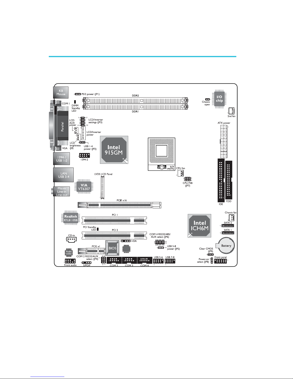
System Board Layout
Chapter 2 - Hardware Installation
17
2
Hardware Installation
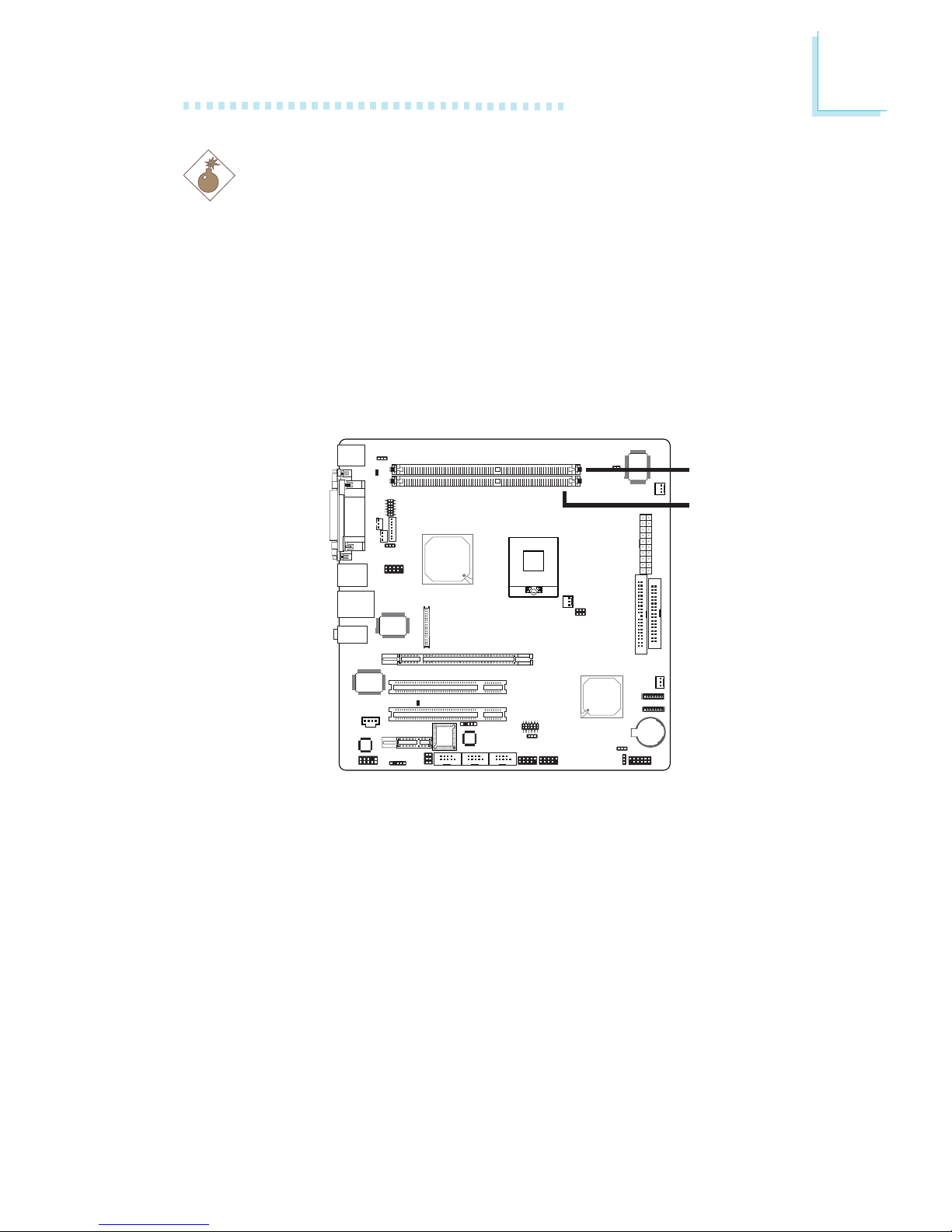
System Memory
Warning:
Electrostatic discharge (ESD) can damage your system board, processor, disk drives, add-in boards, and other components. Perform the
upgrade instruction procedures described at an ESD workstation only.
If such a station is not available, you can provide some ESD
protection by wearing an antistatic wrist strap and attaching it to a
metal part of the system chassis. If a wrist strap is unavailable,
establish and maintain contact with the system chassis throughout
any procedures requiring ESD protection.
The system board supports DDR SDRAM DIMM. Double Data
Rate SDRAM (DDR SDRAM) is a type of SDRAM that doubles the
data rate through reading and writing at both the rising and falling
edge of each clock. This effectively doubles the speed of operation
therefore doubling the speed of data transfer.
BIOS Setting
Configure the system memory in the Advanced Chipset Features
submenu of the BIOS.
.
.
.
.
.
.
.
.
DDR 2
DDR 1
18
2
Hardware Installation
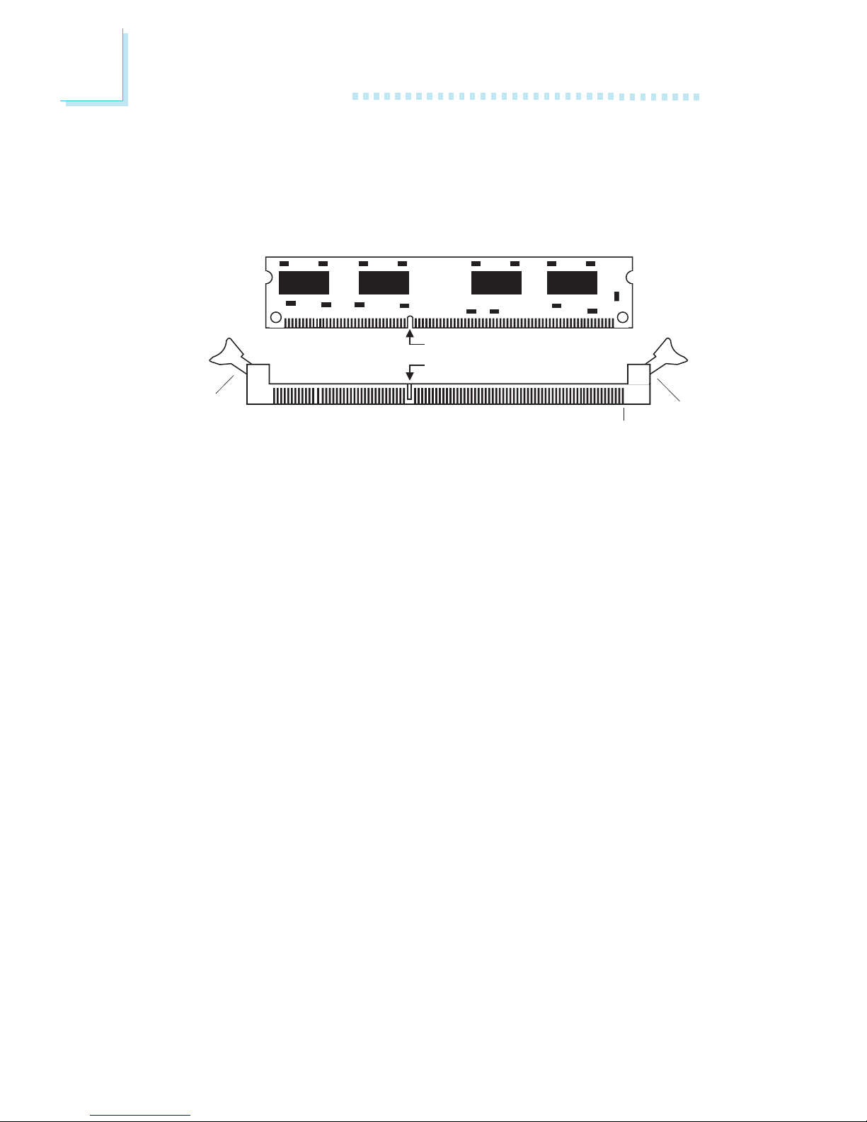
Installing the DIM Module
A DIM module simply snaps into a DIMM socket on the system
board. Pin 1 of the DIM module must correspond with Pin 1 of the
socket.
1. Pull the “tabs” which are at the ends of the socket to the side.
2. Position the DIMM above the socket with the “notch” in the
module aligned with the “key” on the socket.
3. Seat the module vertically into the socket. Make sure it is
completely seated. The tabs will hold the DIMM in place.
Pin 1
Notch
Key
Tab
Tab
19
2
Hardware Installation
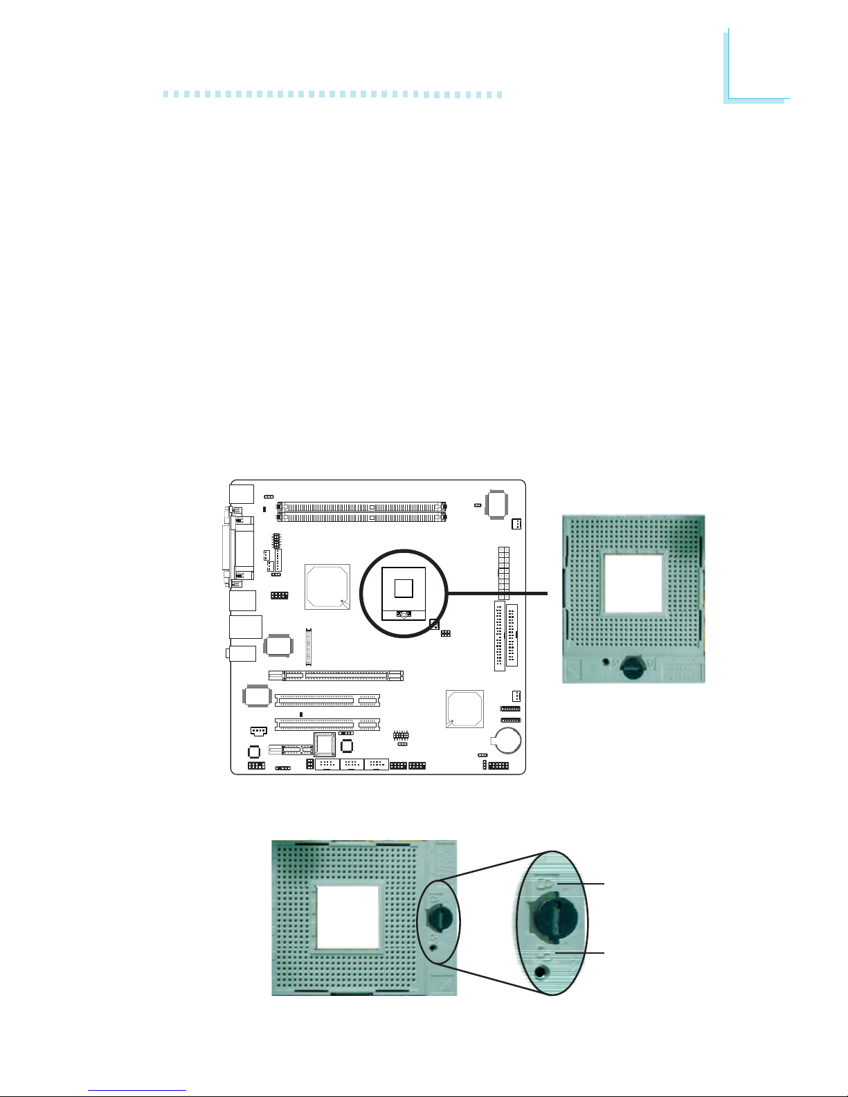
CPU
Overview
The system board is equipped with a surface mount mPGA479M
(Socket 479) CPU socket. This socket is exclusively designed for
installing an Intel® Pentium® M / Celeron® M processor.
Installing the CPU
1. Make sure the PC and all other peripheral devices connected to
it has been powered down.
2. Disconnect all power cords and cables.
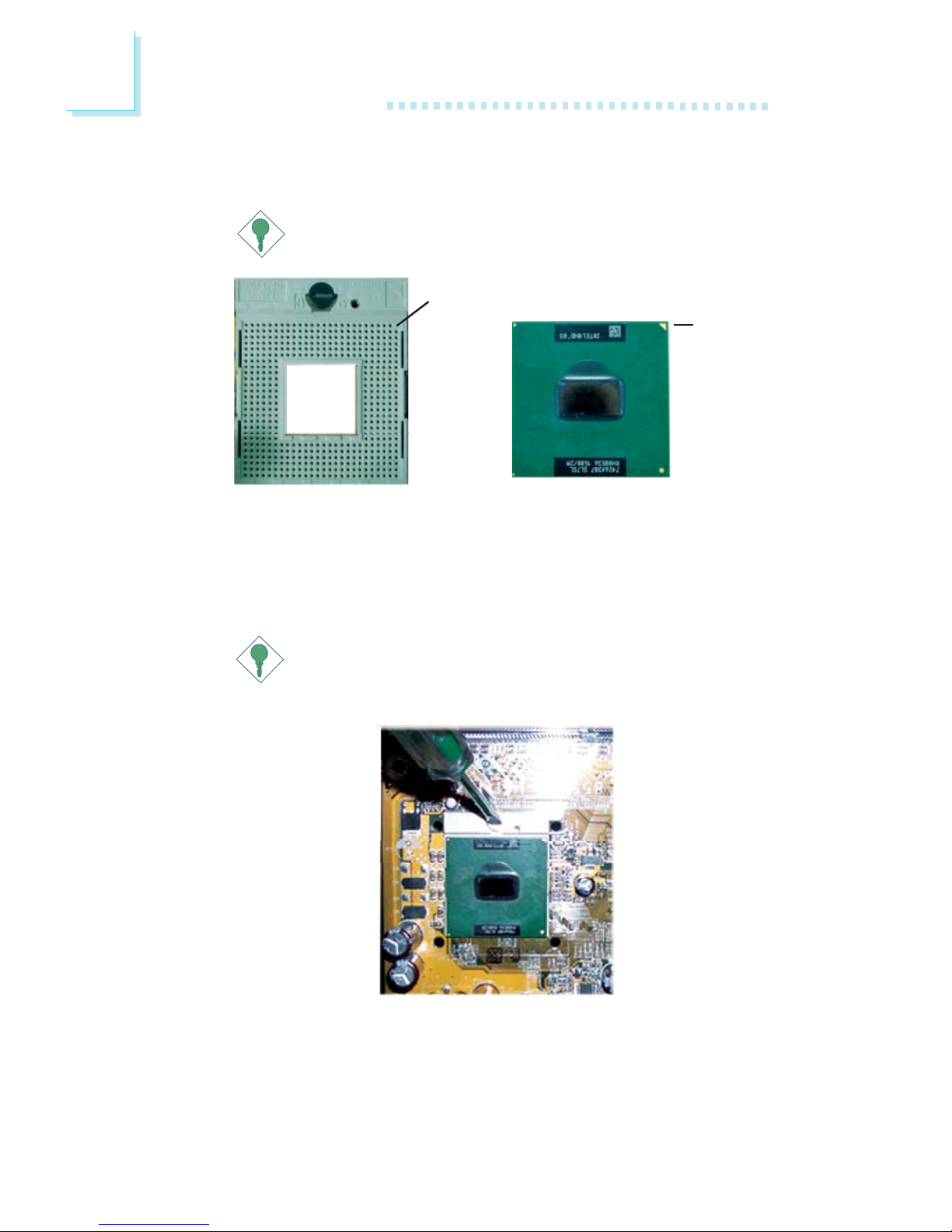
3. Locate the 479-pin CPU socket on the system board.
X
4. Use a screwdriver to turn the screw to its unlock position.
Lock
Unlock
20
2
Hardware Installation
5. Position the CPU above the socket. The gold triangular mark on
the CPU must align with pin 1 of the CPU socket.
Important:
Handle the CPU by its edges and avoid touching the pins.
6. Insert the CPU into the socket until it is seated in place. The
CPU will fit in only one orientation and can easily be inserted
without exerting any force. Use a screwdriver to turn the screw
to its lock position.
Important:
Do not force the CPU into the socket. Forcing the CPU into
the socket may bend the pins and damage the CPU.
Gold
triangular
mark
Pin 1 of the socket
21
2
Hardware Installation
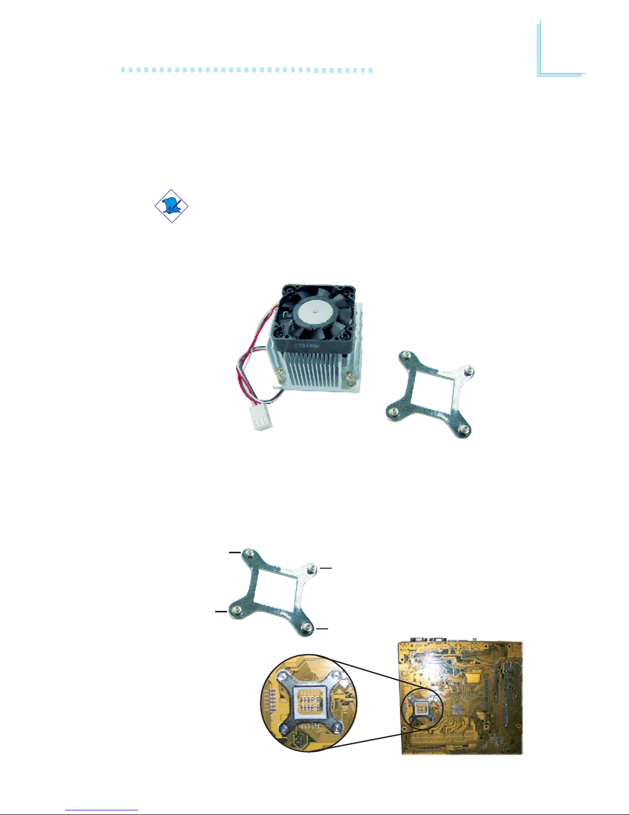
Installing the Fan and Heat Sink
The CPU must be kept cool by using a CPU fan with heat sink.
Without sufficient air circulation across the CPU and heat sink, the
CPU will overheat damaging both the CPU and system board.
Note:
• Use only the fan and heat sink assembly included in the
system board package.
• The fan and heat sink package contains the fan and heat
sink assembly, and a retension module base.
CPU fan and
heat sink assembly
Retention
module base
1. Match and insert the screw holes of the retention module base
to the mounting holes around the CPU socket from the bottom
through the top of the system board.
Screw hole
Screw hole
Screw hole
Screw hole
Buttom view of the system board
22
2
Hardware Installation
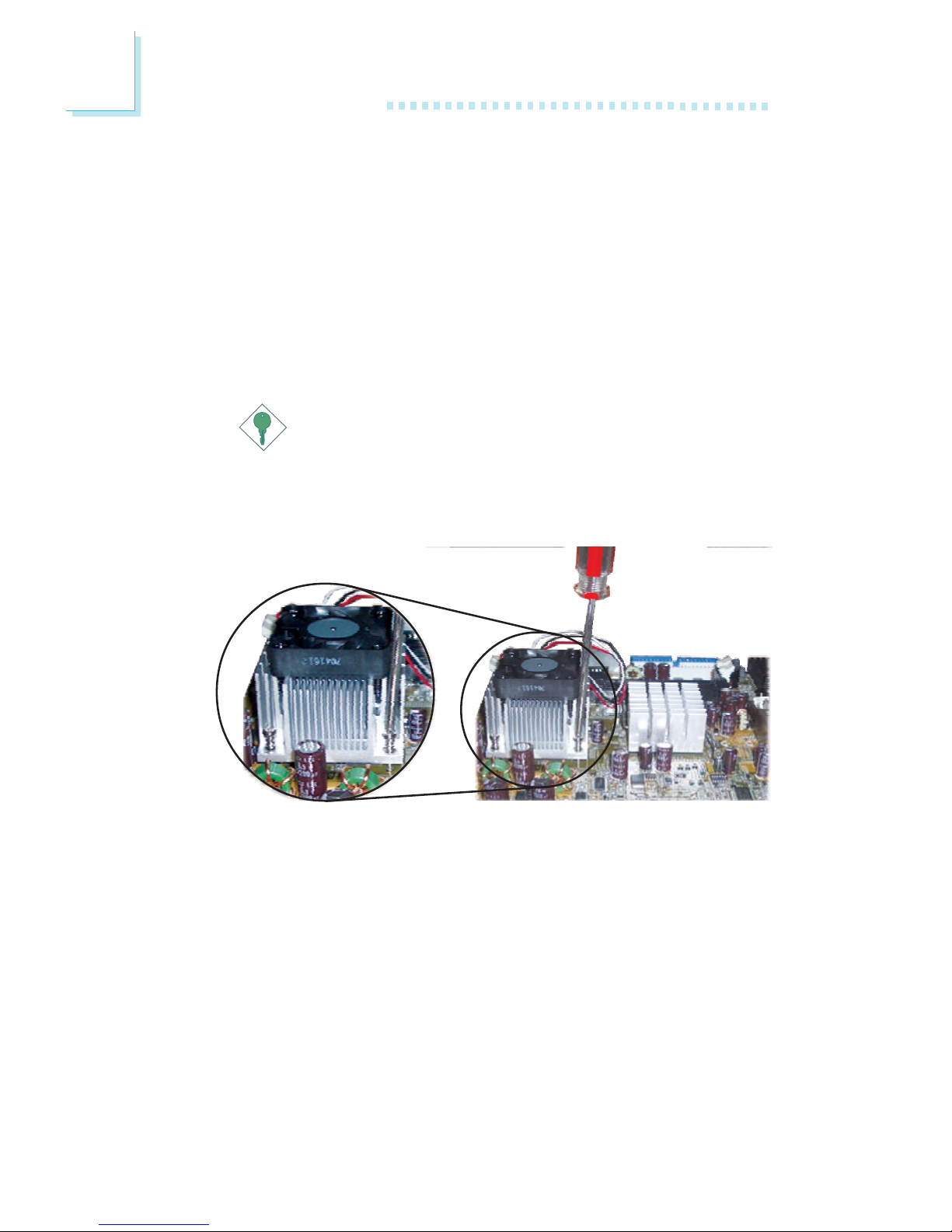
2. Place the heat sink on top of the CPU. The 4 screws around the
heat sink must match the screw holes of the retention module
base. Refer to the figure below for the correct position of the
heat sink. This is important so that the fan / heat sink will
provide adequate cooling to the components of the system
board.
Turn each Phillips head screw half way down first to initially
stabilize the heat sink onto the system board, then finally tighten
each screw.
Important:
Do not turn the first screw all the way down followed by
the next and so on. This is to avoid imbalance which might
cause cracks or fractures to the CPU and/or heat sink
assembly.
23
2
Hardware Installation
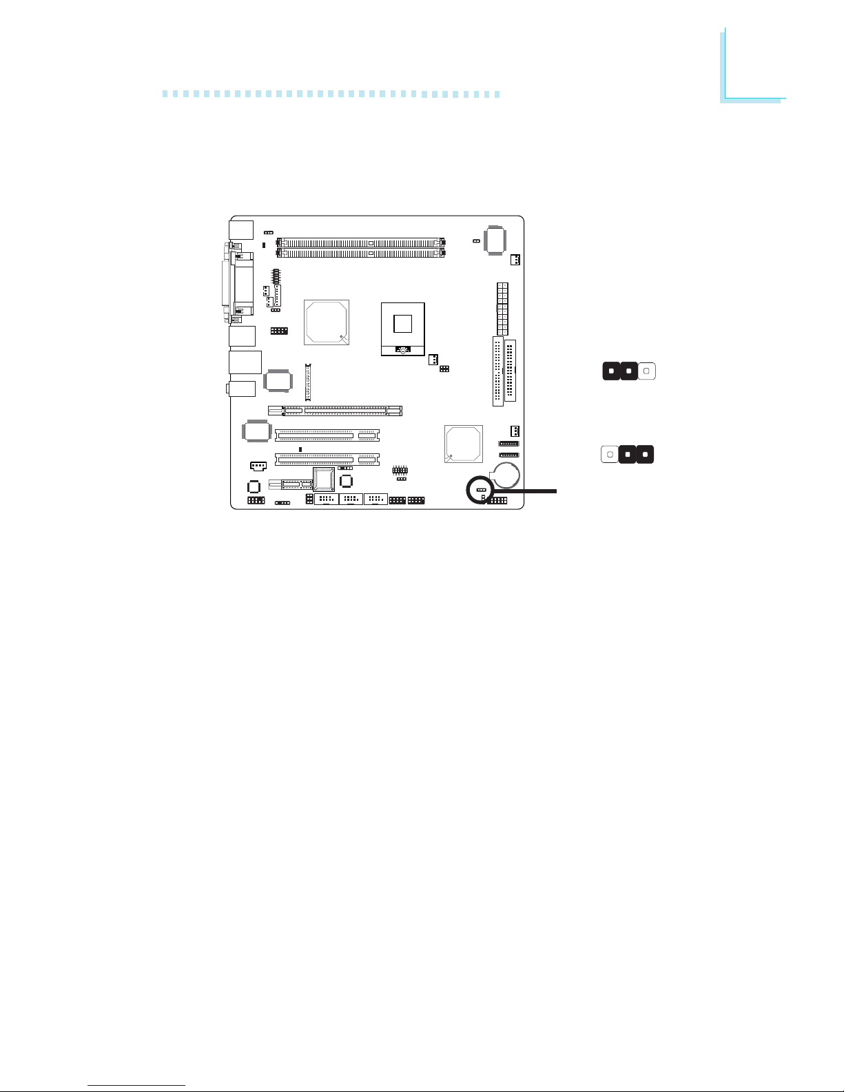
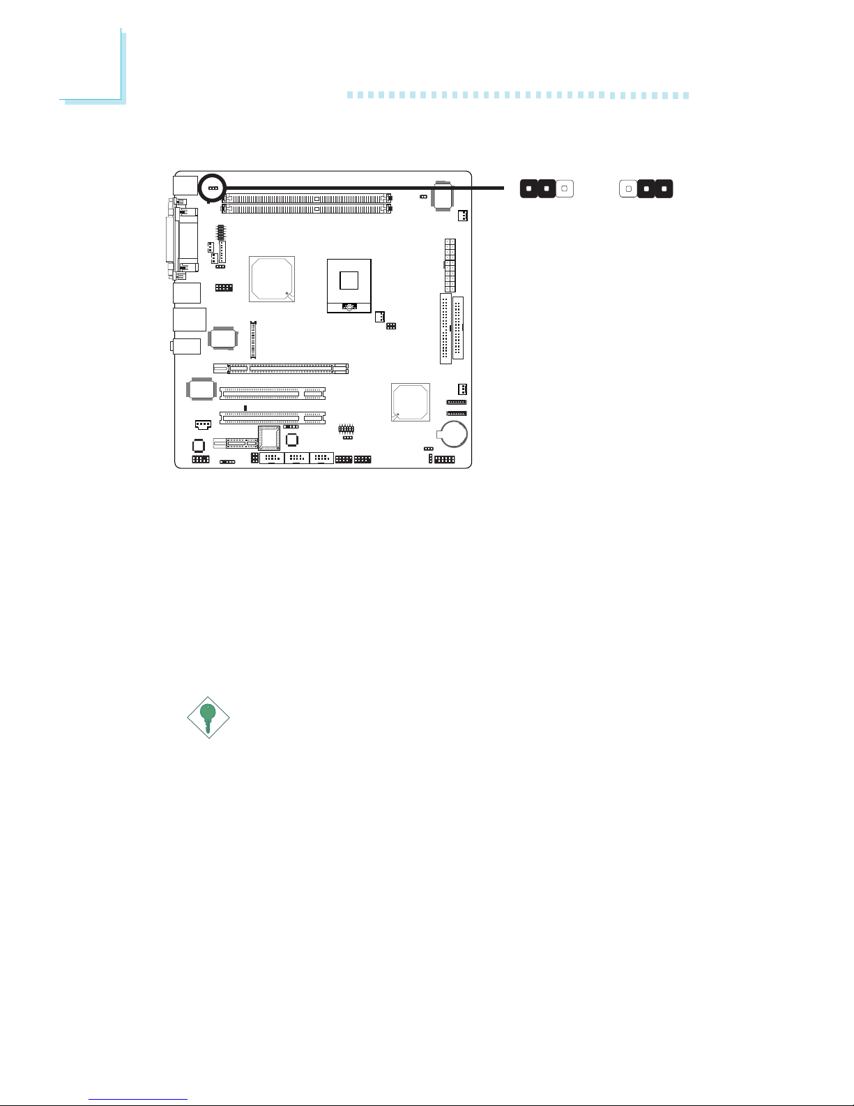
Jumper Settings
Clear CMOS Data
If you encounter the following,
a) CMOS data becomes corrupted.
b) You forgot the supervisor or user password.
you can reconfigure the system with the default values stored in the
ROM BIOS.
To load the default values stored in the ROM BIOS, please follow
the steps below.
1. Power-off the system and unplug the power cord.
2. Set JP9 pins 2 and 3 to On. Wait for a few seconds and set JP9
back to its default setting, pins 1 and 2 On.
3. Now plug the power cord and power-on the system.
2-3 On:
Clear CMOS Data
1-2 On: Normal
(default)
X
JP9
312
312
24
2
Hardware Installation
JP1 is used to select the power of the PS/2 keyboard/mouse port.
Selecting 5VSB will allow you to use the PS/2 keyboard or PS/2
mouse to wake up the system.
BIOS Setting
Configure the PS/2 keyboard/mouse wake up function in the
Integrated Peripherals submenu (“Super IO Device” section) of the
BIOS. Refer to chapter 3 for more information.
Important:
The 5VSB power source of your power supply must support
≥
720mA.
PS/2 Power Select
1-2 On: 5V
(default)
2-3 On: 5VSB
X
JP1
312312
25
2
Hardware Installation
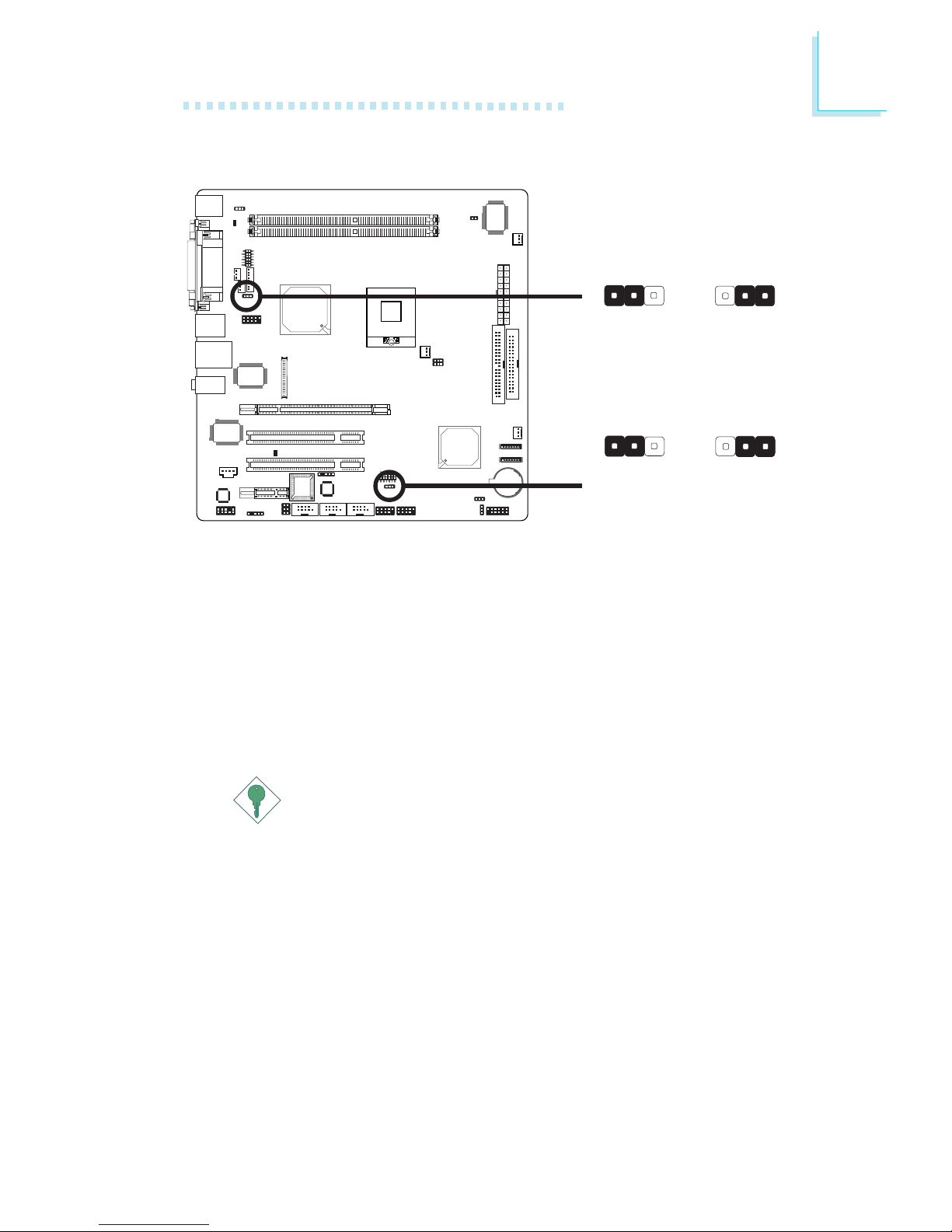
USB Power Select
X
USB 1-4
(JP2)
JP2 and JP5 are used to select the power of the USB ports.
Selecting 5VSB will allow you to use the USB keyboard or USB
mouse to wake up the system.
BIOS Setting
“USB KB Wake-Up From S3” in the Power Management Setup
submenu of the BIOS must be set to Enabled. Refer to chapter 3
for more information.
Important:
If you are using the Wake-On-USB Keyboard/Mouse function for
2 USB ports, the 5VSB power source of your power supply
must support ≥1.5A. For 3 or more USB ports, the 5VSB
power source of your power supply must support ≥2A.
1-2 On: 5V
(default)
2-3 On: 5VSB
312312
X
USB 5-8
(JP5)
1-2 On: 5V
(default)
2-3 On: 5VSB
312312
26
2
Hardware Installation
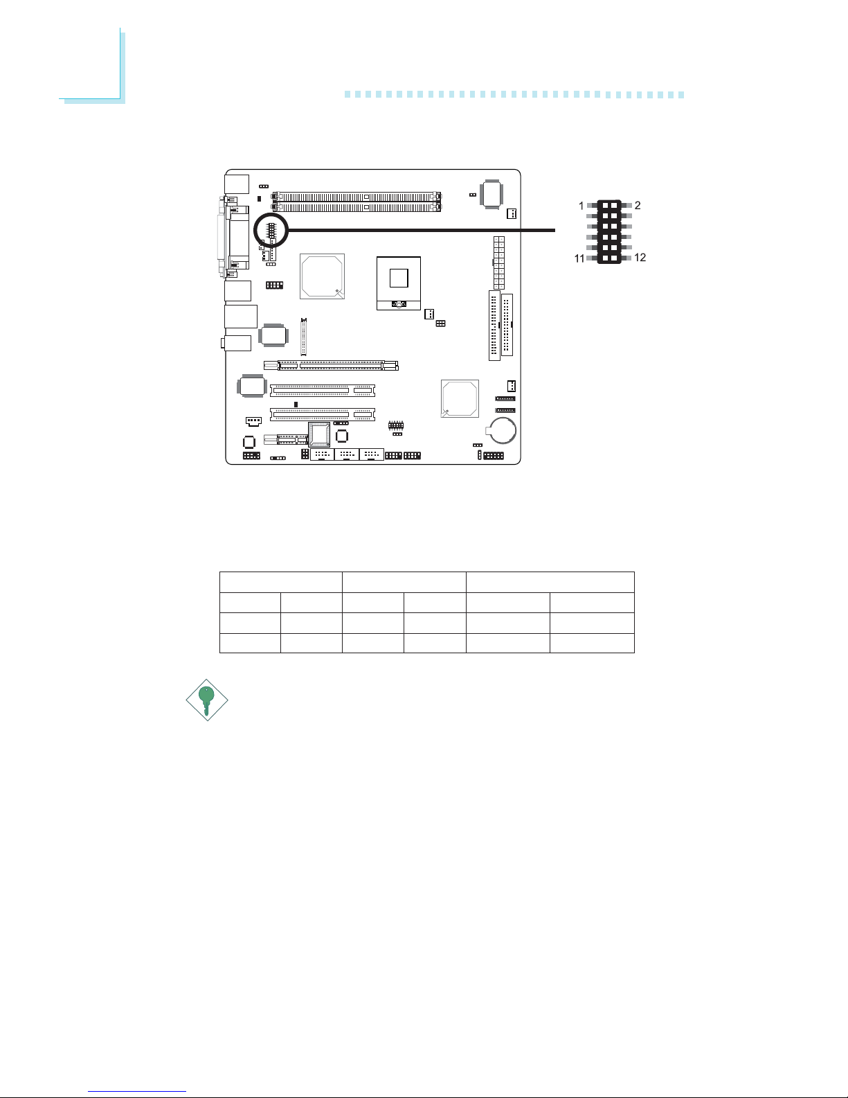
LCD/Inverter Settings
JP3 is used to select the power supplied to the LCD panel and to
configure the inverter.
X
JP3
Important:
Before powering-on the system, make sure JP3’s setting
matches the LCD panel’s specification. Selecting the incorrect
voltage will seriously damage the LCD panel.
LCD/Inverter Settings - JP3
5V
3.3V
12V
Panel Power
1-3 On
3-5 On
7-9 On
5V
12V
Inverter On Level
2-4 On
4-6 On
Active Low
Active High
Inverter On/Off Select
8-10 On
10-12 On
27
2
Hardware Installation
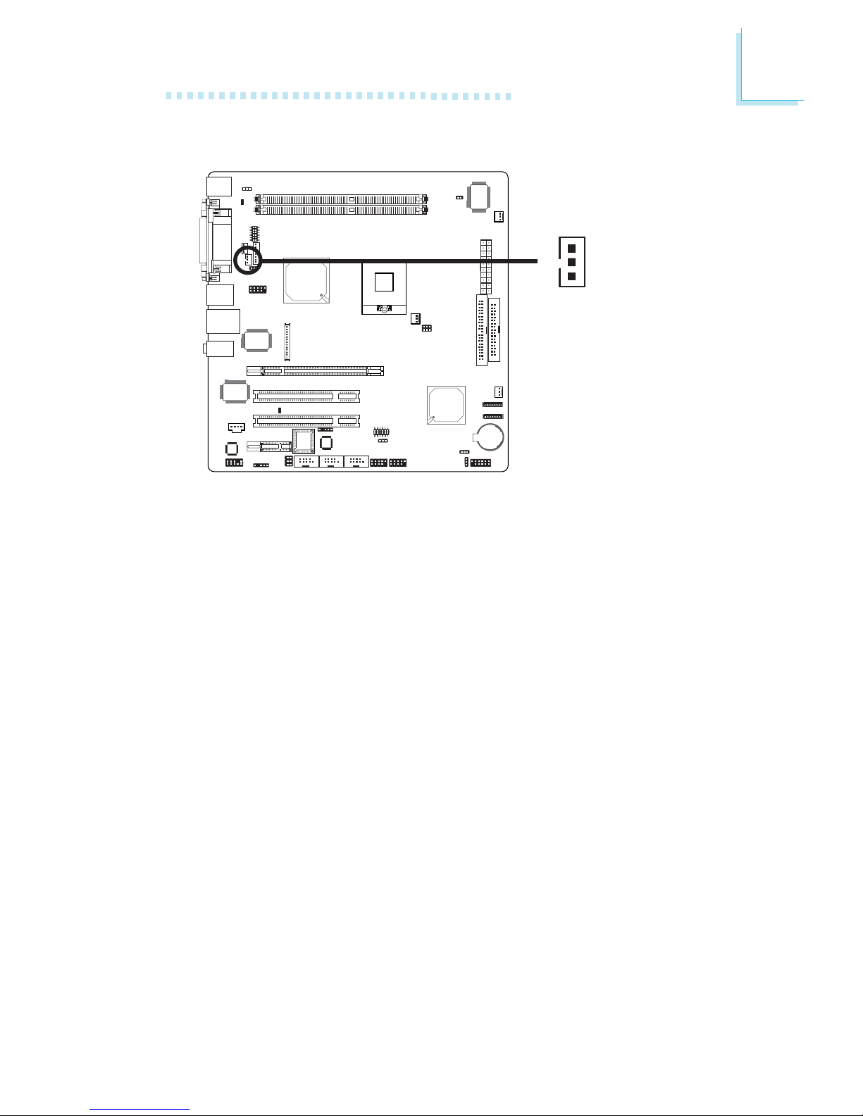
LCD Brightness Control (Voltage Level Adjust)
X
J4
Use J4 to connect to the LCD Brightness Control button of the
LCD Display Panel. It is used to adjust the brightness of the LCD
Display Panel. Increasing or decreasing the voltage to control the
LCD panel’s brightness varies among Inverters. You must refer to the
Inverter’s specification to make the appropriate adjustment to the
brightness of the LCD panel.
3
1
2
1-2 On:
Increases the voltage level
2-3 On:
Decreases the voltage level
28
2
Hardware Installation
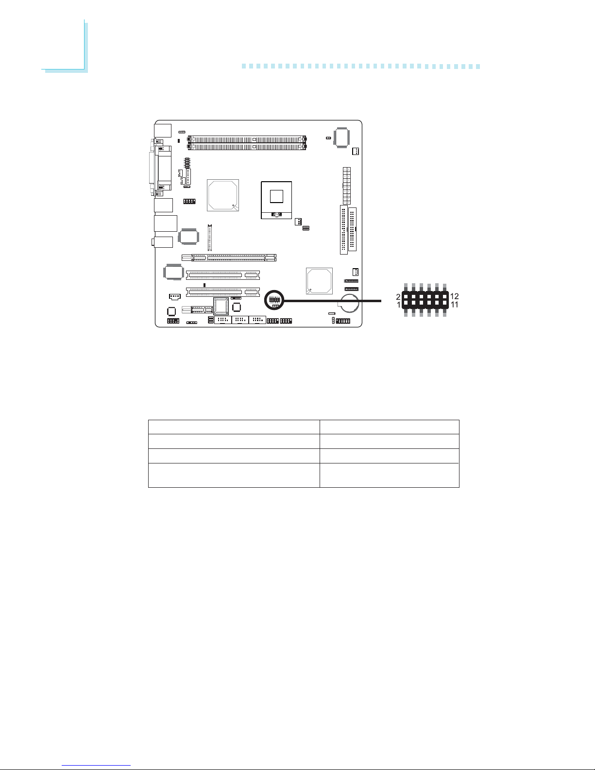
JP6 is used to set COM 4 to RS-232 or RS-485. If the serial device
connected to this port requires 5V/12V power from the system
board, set JP6 pins 1-3, 2-4, 9-11 and 10-12 to On. This setting
automatically sets COM 4 at RS-232.
COM 4 RS232/RS485/AUX Select
X
JP6
JP6
1-3, 2-4, 7-9, 8-10 On
3-5, 4-6, 7-9, 8-10 On
1-3, 2-4, 9-11 (12V),
10-12 (5V) On
COM 4 RS232/RS485/AUX Select
RS232 (default)
RS485
Auxiliary power
29
2
Hardware Installation
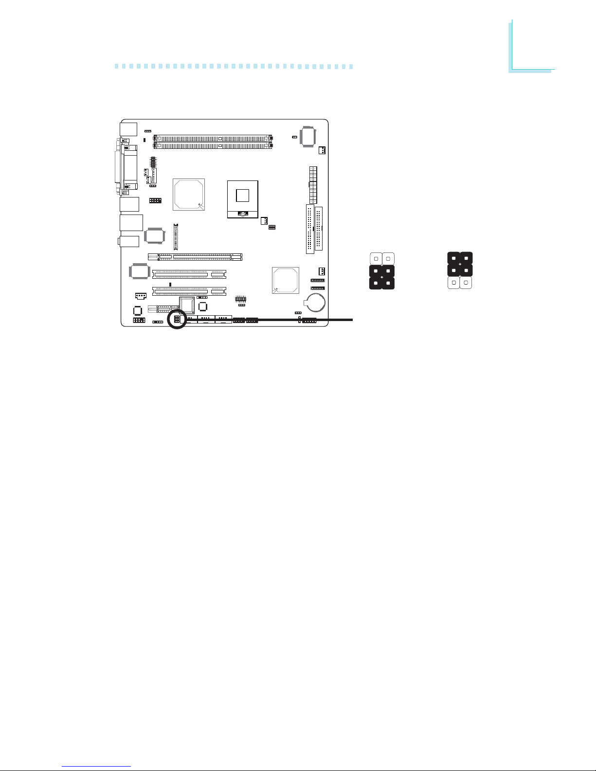
COM 2 is an RS-232 port. If the serial device connected to this
port requires 5V/12V power from the system board, set JP4 pins
3-5 and 4-6 to On. Otherwise, leave this jumper’s setting at 1-3, 2-4
On.
COM 2 RS232/AUX Select
X
JP4
3-5 (5V),
4-6 (12V) On:
Auxiliary power
1-3, 2-4 On:
RS232
(default)
1
3
2
6
4
5
1
3
2
6
4
5
30
2
Hardware Installation
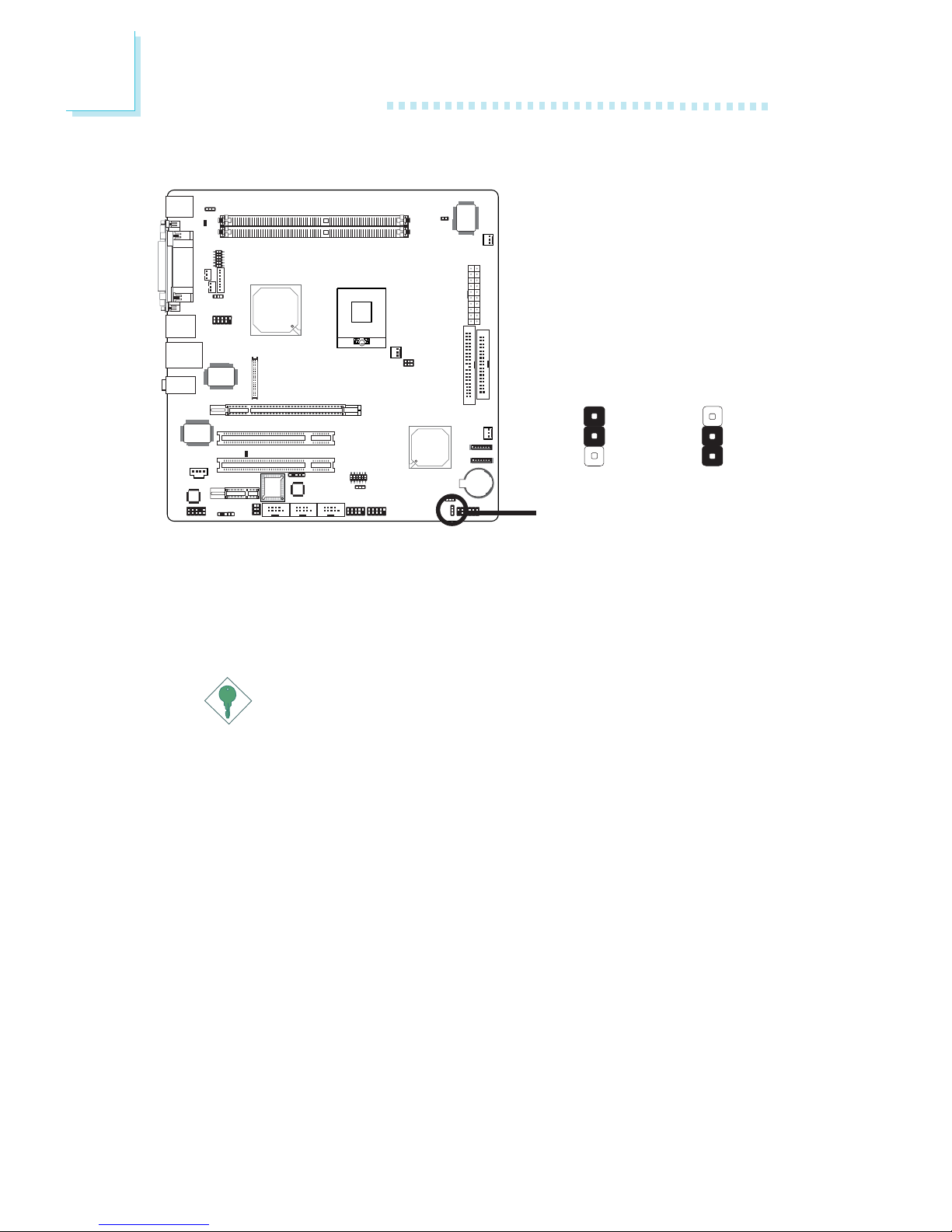
X
JP8
Power-on Select
1-2 On:
Power-on via
AC power
2-3 On:
Power-on via
power button
(default)
JP8 is used to select the method of powering on the system. If you
want the system to power-on whenever AC power comes in, set
JP8 pins 1 and 2 to On. If you want to use the power button, set
pins 2 and 3 to On.
Important:
If you want the system to automatically power-on when power
returns after an AC power failure, you must:
1. Set JP8 pins 1 and 2 to On.
2. The PWRON After PWR-Fail field must be set to "On".
(Integrated Peripherals submenu, Super I/O Device section
of the BIOS).
1
3
2
1
3
2
 Loading...