

DFI G5C630-DR User Manual

G5C630-DR
System Board
User’s Manual
935-G5C631-000G
A00100701

Copyright
This publication contains information that is protected by copyright.
No part of it may be reproduced in any form or by any means or
used to make any transformation/adaptation without the prior written permission from the copyright holders.
This publication is provided for informational purposes only. The
manufacturer makes no representations or warranties with respect to
the contents or use of this manual and specifically disclaims any express or implied warranties of merchantability or fitness for any particular purpose. The user will assume the entire risk of the use or the
results of the use of this document. Further, the manufacturer reserves the right to revise this publication and make changes to its
contents at any time, without obligation to notify any person or entity of such revisions or changes.
© 2007. All Rights Reserved.
Trademarks
Product names or trademarks appearing in this manual are for identification purpose only and are the properties of the respective owners.

FCC and DOC Statement on Class B
This equipment has been tested and found to comply with the limits
for a Class B digital device, pursuant to Part 15 of the FCC rules.
These limits are designed to provide reasonable protection against
harmful interference when the equipment is operated in a residential
installation. This equipment generates, uses and can radiate radio frequency energy and, if not installed and used in accordance with the
instruction manual, may cause harmful interference to radio communications. However, there is no guarantee that interference will not
occur in a particular installation. If this equipment does cause harmful
interference to radio or television reception, which can be determined
by turning the equipment off and on, the user is encouraged to try
to correct the interference by one or more of the following measures:
• Reorient or relocate the receiving antenna.
• Increase the separation between the equipment and the receiver.
• Connect the equipment into an outlet on a circuit different from
that to which the receiver is connected.
• Consult the dealer or an experienced radio TV technician for
help.
Notice:
1. The changes or modifications not expressly approved by the
party responsible for compliance could void the user's authority
to operate the equipment.
2. Shielded interface cables must be used in order to comply with
the emission limits.

Table of Contents
About this Manual................................................................................
Warranty.................................................................................................
Static Electricity Precaution................................................................
Safety Measures.....................................................................................
About the Package...............................................................................
Before Using the System Board.........................................................
Chapter 1 - Introduction....................................................................
Specifications...................................................................................................................................
Special Features of the System Board..................................................................
Chapter 2 - Hardware Installation....................................................
System Board Layout ..........................................................................................................
System Memory..........................................................................................................................
CPU.......................................................................................................................................................
Jumper Settings............................................................................................................................
Rear Panel I/O Ports.............................................................................................................
I/O Connectors..........................................................................................................................
Chapter 3 - BIOS Setup......................................................................
Award BIOS Setup Utility.................................................................................................
Updating the BIOS..................................................................................................................
Chapter 4 - Supported Softwares.....................................................
Drivers, Utilities and Software Applications......................................................
Installation Notes.......................................................................................................................
Appendix A - Watchdog Timer.............................................................
Appendix B - System Error Messages...............................................
POST Beep.................................................................................................................................
Error Messages.........................................................................................................................
Appendix C - Troubleshooting..........................................................
Troubleshooting Checklist...............................................................................................
5
5
6
6
7
7
8
8
10
14
14
15
19
23
28
39
57
57
97
99
99
112
113
115
115
115
117

About this Manual
An electronic file of this manual is included in the CD. To view the
user’s manual in the CD, insert the CD into a CD-ROM drive. The
autorun screen (Main Board Utility CD) will appear. Click “User’s
Manual” on the main menu.
Warranty
1. Warranty does not cover damages or failures that arised from
misuse of the product, inability to use the product, unauthorized
replacement or alteration of components and product specifications.
2. The warranty is void if the product has been subjected to physical abuse, improper installation, modification, accidents or unauthorized repair of the product.
3. Unless otherwise instructed in this user’s manual, the user may
not, under any circumstances, attempt to perform service, adjustments or repairs on the product, whether in or out of warranty.
It must be returned to the purchase point, factory or authorized
service agency for all such work.
4. We will not be liable for any indirect, special, incidental or
consequencial damages to the product that has been modified
or altered.

Introduction
1
6
Static Electricity Precautions
It is quite easy to inadvertently damage your PC, system board,
components or devices even before installing them in your system
unit. Static electrical discharge can damage computer components
without causing any signs of physical damage. You must take extra
care in handling them to ensure against electrostatic build-up.
1. To prevent electrostatic build-up, leave the system board in its
anti-static bag until you are ready to install it.
2. Wear an antistatic wrist strap.
3. Do all preparation work on a static-free surface.
4. Hold the device only by its edges. Be careful not to touch any of
the components, contacts or connections.
5. Avoid touching the pins or contacts on all modules and connectors. Hold modules or connectors by their ends.
Important:
Electrostatic discharge (ESD) can damage your processor,
disk drive and other components. Perform the upgrade instruction procedures described at an ESD workstation
only. If such a station is not available, you can provide
some ESD protection by wearing an antistatic wrist strap
and attaching it to a metal part of the system chassis. If a
wrist strap is unavailable, establish and maintain contact
with the system chassis throughout any procedures requiring ESD protection.
Safety Measures
To avoid damage to the system:
• Use the correct AC input voltage range
..
..
.
To reduce the risk of electric shock:
• Unplug the power cord before removing the system chassis
cover for installation or servicing. After installation or servicing,
cover the system chassis before plugging the power cord.
Battery:
• Danger of explosion if battery incorrectly replaced.
• Replace only with the same or equivalent type recommend
by
the manufacturer.
• Dispose of used batteries according to the battery manufacturer’s
instructions.

1
Introduction
7
About the Package
The system board package contains the following items. If any of
these items are missing or damaged, please contact your dealer or
sales representative for assistance.
; The system board
; A user’s manual
; One IDE cable
; One FDD cable
; Two USB port cables
; Two Serial ATA data cables
; Two Serial ATA power cables
; One “Main Board Utility” CD
; Two RAID driver floppy diskettes
; One I/O shield
The system board and accessories in the package may not come
similar to the information listed above. This may differ in accordance
to the sales region or models in which it was sold. For more information about the standard package in your region, please contact
your dealer or sales representative.
Before Using the System Board
Before using the system board, prepare basic system components.
If you are installing the system board in a new system, you will need
at least the following internal components.
• A CPU
• Memory module
• Storage devices such as hard disk drive, CD-ROM, etc.
You will also need external system peripherals you intend to use
which will normally include at least a keyboard, a mouse and a video
display monitor.

Introduction
1
8
Processor
Chipset
System Memory
BIOS
Energy Efficient
Design
Damage Free
Intelligence
Graphics
• Intel® CoreTM Duo/Solo mobile processor
Intel® CoreTM 2 Duo mobile processor
Intel® CoreTM processor-based Celeron® M 65nm mobile processor
- 667MHz/533MHz Front Side Bus
• Processor socket: mPGA478
• Intel
®
chipset
- Intel® 945GM Express chipset
- Intel® 82801GR I/O Controller Hub (ICH7R)
• Two 240-pin DDR2 DIMM sockets
• Supports dual channel (128-bit wide) memor y interface
• Supports 400MHz, 533MHz and 667MHz DDR2 SDRAM
• Supports maximum of 4GB system memory using 256Mbit,
512Mbit or 1Gbit technology for x8 and x16 devices
• Award BIOS
• 4Mbit flash memory
• Supports ACPI specification and OS Directed Power Management
• Supports ACPI STR (Suspend to RAM) function (optional)
• Wake-On-Events include:
- Wake-On-PS/2 Keyboard/Mouse
- Wake-On-USB Keyboard/Mouse
- Wake-On-LAN and Wake-On-Ring
- RTC timer to power-on the system
• System power management supported
• Microsoft
®
/Intel® APM 1.2 compliant
• Soft Power supported - ACPI v1.0a specification
• AC power failure recovery
• Monitors CPU/system temperature and overheat alarm
• Monitors CPU(V)/1.05V/1.5V/dimm(V)/12V/VBAT(V)/3.3V/5V/
V3.3sb(V) voltages and failure alarm
• Monitors CPU/system fan speed and failure alarm
• Read back capability that displays temperature, voltage and fan
speed
• Watchdog timer function
• Integrated Intel Graphics Media Accelerator 950
- 250MHz core render clock and 200MHz core display
clock
- Up to 224 MB maximum video memory
- 1600x1200 at 75 Hz maximum resolution
- Suppor ts DVI port through Serial Digital Video Out (SDVO)
interface
-`Dual screen display through CRT and DVI ports
Chapter 1 - Introduction
Specifications

1
Introduction
9
Audio
LAN
Serial ATA
IDE Interface
Rear Panel I/O
Ports
I/O Connectors
Expansion Slots
Temperature
Humidity
PCB
• Realtek ALC655 AC'97 audio CODEC
• 16-bit stereo full-duplex CODEC with 48KHz sampling rate
• High quality differential CD input
• S/PDIF interface
• 5.1-channel audio output
• Two Realtek PCI Express Gigabit controllers
• Suppor ts 10Mbps, 100Mbps and 1Gbps data transmission
• IEEE 802.3 (10/100Mbps) and IEEE 802.3ab (1Gbps) compliant
• Supports four SATA (Serial ATA) interfaces which are compliant
with SATA 1.0 specification
• SATA speed up to 3Gb/s
• RAID 0, RAID 1, RAID 0+1 and RAID 5
• One IDE connector supports up to two IDE devices
• Supports Ultra ATA 100/66/33
• 1 mini-DIN-6 PS/2 mouse port
• 1 mini-DIN-6 PS/2 keyboard port
• 2 DB-9 serial por ts
• 1 DB-15 VGA port
• 1 DVI-I port
• 2 RJ45 LAN por ts
• 4 USB 2.0/1.1 ports
• Mic-in, line-in and line-out
• 2 connectors for 4 additional external USB 2.0/1.1 ports
• 1 DIO connector
• 1 parallel connector
• 1 front audio connector for line-out and mic-in jacks
• 1 CD-in internal audio connector
• 1 S/PDIF-in/out connector
• 1 connector for IrDA interface
• 4 Serial ATA connectors
• 1 40-pin IDE connector
• 1 floppy connector
• 1 24-pin ATX power connector
• 1 4-pin 12V power connector
• 1 chassis open connector
• 1 front panel connector
• 3 fan connectors
• 1 PCI Express x16 slot
• 1 PCI Express x1 slot
• 5 PCI slots
•0
o
C to 60oC
• 10% to 90%
• 6 layers, ATX form factor
• 30.5cm (12") x 24.4cm (9.6")

Introduction
1
10
Features
The Watchdog Timer function allows your
application to regularly “clear” the system at
the set time interval. If the system hangs or fails to function, it will
reset at the set time interval so that your system will continue to
operate.
DDR2 is a higher performance DDR technology
whose data transfer rate delivers bandwidth of 4.3
GB per second and beyond. That is twice the speed of the conventional DDR without increasing its power consumption. DDR2
SDRAM modules work at 1.8V supply compared to 2.6V memory
voltage for DDR modules. DDR2 also incorporates new innovations
such as the On-Die Termination (ODT) as well as larger 4-bit prefetch against DDR which fetches 2 bits per clock cycle.
The Intel 945GM northbridge chip comes integrated
with the Intel Graphics Media Accelerator 950 delivering exceptional 3D graphics performance. It supports analog CRT
and TV-out interfaces.
DVI (Digital Visual Interface) is a form of video inter-
face technology made to maximize the quality of flat
panel LCD monitors and modern video graphics cards. Data is
transmitted using the TMDS (Transition Minimized Differential
Signaling) protocol, providing a digital signal from the PC’s graphics
subsystem to the display.
The audio jacks at the rear panel will
support 5.1-channel audio only when the
audio utility is configured to support this function. The mic-in at the
rear will be disabled. Use the front audio’s mic-in jack.
watchdog timer
5.1-channel audio
DDR2
graphics
DVI

1
Introduction
11
S/PDIF is a standard audio file transfer format that
transfers digital audio signals to a device without
having to be converted first to an analog format. This prevents the
quality of the audio signal from degrading whenever it is converted
to analog. S/PDIF is usually found on digital audio equipment such as
a DAT machine or audio processing device. The S/PDIF connector on
the system board sends surround sound and 3D audio signal outputs to amplifiers and speakers and to digital recording devices like
CD recorders.
Serial ATA is a storage interface that is compliant
with SATA 1.0 specification. With speed of up to
3Gbps, it improves hard drive performance faster than the standard
parallel ATA whose data transfer rate is 100MB/s. The Intel chip allows configuring RAID on Serial ATA drives. It supports RAID 0, RAID
1, RAID 0+1 and RAID 5.
The two Realtek PCI Express Gigabit LAN controllers support up to 1Gbps data transmission.
The system board is equipped with an IrDA connec-
tor for wireless connectivity between your computer
and peripheral devices. The IRDA (Infrared Data Association) specification supports data transfers of 115K baud at a distance of 1
meter.
The system board supports USB 2.0 and USB 1.1
ports. USB 1.1 supports 12Mb/second bandwidth
while USB 2.0 supports 480Mb/second bandwidth providing a
marked improvement in device transfer speeds between your computer and a wide range of simultaneously accessible external Plug
and Play peripherals.
USB
SERIAL ATA
irda
gigabit lan
S/PDIF

Introduction
1
12
This feature allows the system that is in the
Suspend mode or Soft Power Off mode to
wake-up/power-on to respond to calls coming from an external modem or respond to calls from a modem PCI card that uses the PCI
PME (Power Management Event) signal to remotely wake up the
PC.
Important:
The 5V_standby power source of your power supply must support ≥720mA.
This feature allows the network to remotely
wake up a Soft Power Down (Soft-Off) PC.
It is supported via the onboard LAN port or via a PCI LAN card
that uses the PCI PME (Power Management Event) signal. However,
if your system is in the Suspend mode, you can power-on the system
only through an IRQ or DMA interrupt.
Important:
The 5V_standby power source of your power supply must support ≥720mA.
This function allows you to use the PS/2 key-
board or PS/2 mouse to power-on the system.
Important:
The 5V_standby power source of your power supply must support ≥720mA.
This function allows you to use a USB keyboard or USB mouse to wake up a system
from the S3 (STR - Suspend To RAM) state.
Important:
If you are using the Wake-On-USB Keyboard/Mouse function for
2 USB ports, the 5V_standby power source of your power supply must support ≥1.5A. For 3 or more USB ports, the
5V_standby power source of your power supply must support
≥
2A.
wake-on-USB
wake-on-lan
wake-on-PS/2
wake-on-ring

1
Introduction
13
The RTC installed on the system board allows your
system to automatically power-on on the set date
and time.
The system board is designed to meet the ACPI
(Advanced Configuration and Power Interface) specification. ACPI has energy saving features that enables PCs to implement Power Management and Plug-and-Play with operating systems
that support OS Direct Power Management. Currently, only Windows
®®
®®
®
2000/XP supports the ACPI function. ACPI when enabled in
the Power Management Setup will allow you to use the Suspend to
RAM function.
With the Suspend to RAM function enabled, you can power-off the
system at once by pressing the power button or selecting “Standby”
when you shut down Windows
®®
®®
®
2000/XP without having to go
through the sometimes tiresome process of closing files, applications
and operating system. This is because the system is capable of storing all programs and data files during the entire operating session
into RAM (Random Access Memory) when it powers-off. The operating session will resume exactly where you left off the next time you
power-on the system.
Important:
The 5V_standby power source of your power supply must support ≥720mA.
When power returns after an AC power failure, you may choose to either power-on the
system manually or let the system power-on
automatically.
Power failure
recovery
rtc timer
ACPI STR
14
2
Hardware Installation
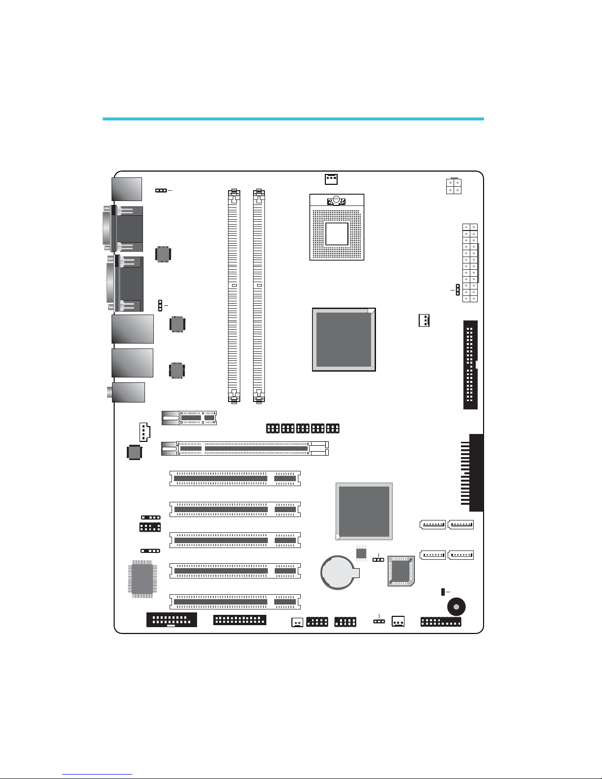
System Board Layout
Chapter 2 - Hardware Installation
1
IrDA
1
PCIE x1
1
Front panel
System fan
1
1
1
USB 2-3
1
USB 0-1
Parallel
1
1
Chassis open
1
SATA 2 SATA 3
SATA 0
SATA 1
1
FDD
1
13
ATX po we r
12 24
DDR2-1 DDR2-2
A
B
C
1
1
Clear CMOS
()JP1
1
PS/2 power
select ( )JP2
1
USB 4-7 power
select ( )JP3
1
CPU fan
Front audio
1
CD-in
1
1
2nd fan
1
+12V power
JP8JP12JP9JP10JP11
Mouse
KB
COM 1
COM 2
LAN 1
USB 7
USB 6
LAN 2
USB 5
USB 4
Mic-in
Line-in
Line-out
1
DIO
Top:VGA
Buttom: DVI-I
1
PCIE x16
PCI 1
PCI 2
PCI 3
PCI 4
PCI 5
Audio
codec
S/PDIF
USB 0-3 power
select ( )JP4
Battery
IDE
1
Power-on
select (JP6)
Realtek
RTL8111B
Realtek
RTL8111B
I/O
chip
1
1 1
mPGA478
SOCKET
Intel
945GM
Intel
ICH7R
132
4
65
132
4
65
132
4
65
132
4
65
132
4
65
Chrontel
CH7307C
SPI Flash
BIOS
Standby
Power LED
PCIE x16 / DVI
select (JP8-JP12)
BIOS
15
2
Hardware Installation
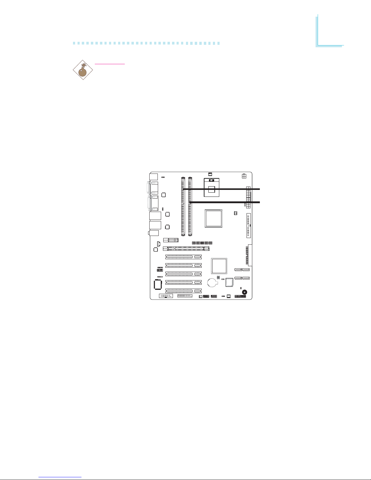
System Memory
Warning:
Electrostatic discharge (ESD) can damage your system board, processor, disk drives, add-in boards, and other components. Perform the
upgrade instruction procedures described at an ESD workstation only.
If such a station is not available, you can provide some ESD
protection by wearing an antistatic wrist strap and attaching it to a
metal part of the system chassis. If a wrist strap is unavailable,
establish and maintain contact with the system chassis throughout
any procedures requiring ESD protection.
.
.
.
.
.
.
.
.
A
B
C
1
Intel
ICH7R
BIOS
DDR2-1
DDR2-2
The two DDR2 DIMM sockets on the system board are divided into
2 channels:
Channel A - DDR2-1
Channel B - DDR2-2

16
2
Hardware Installation
The system board supports the following memory interface.
Single Channel (SC)
Data will be accessed in chunks of 64 bits (8B) from the memory
channels.
Dual Channel (DC)
Data will be accessed in chunks of 128 bits from the memory channels. Dual channel provides better system performance because it
doubles the data transfer rate.
• DIMMs are on the same channel.
• DIMMs in a channel can be identical or
completely different. However, we highly recommend using identical DIMMs.
• Not all slots need to be populated.
• DIMMs of the same memory configura-
tion are on different channels.
Single Channel
Dual Channel
BIOS Setting
Configure the system memory in the Advanced Chipset Features
submenu of the BIOS.
17
2
Hardware Installation
Installing the DIM Module
Note:
The system board used in the following illustrations may not
resemble the actual board. These illustrations are for reference
only.
1. Make sure the PC and all other peripheral devices connected to
it has been powered down.
2. Disconnect all power cords and cables.
3. Locate the DDR2 socket on the system board.
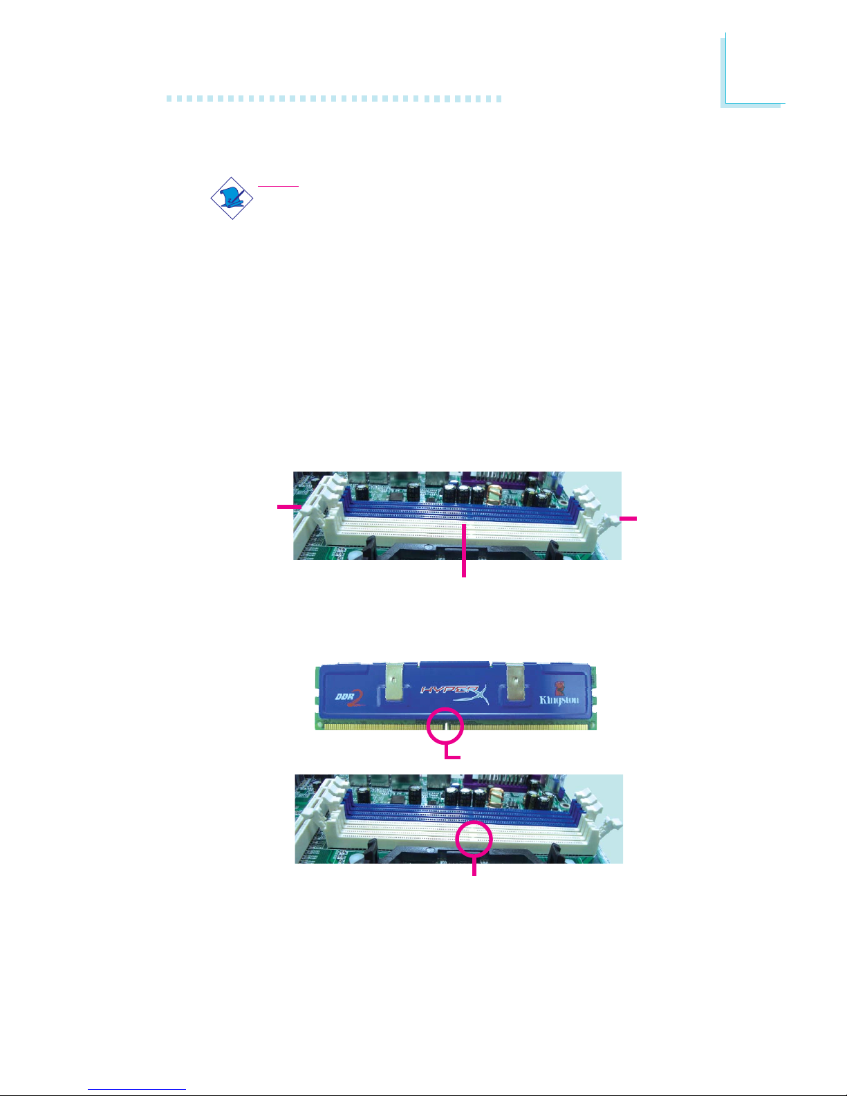
4. Push the “ejector tabs” which are at the ends of the socket to
the side.
Ejector
tab
5. Note how the module is keyed to the socket.
DDR2 sockets
Ejector
tab
Key
Notch
18
2
Hardware Installation
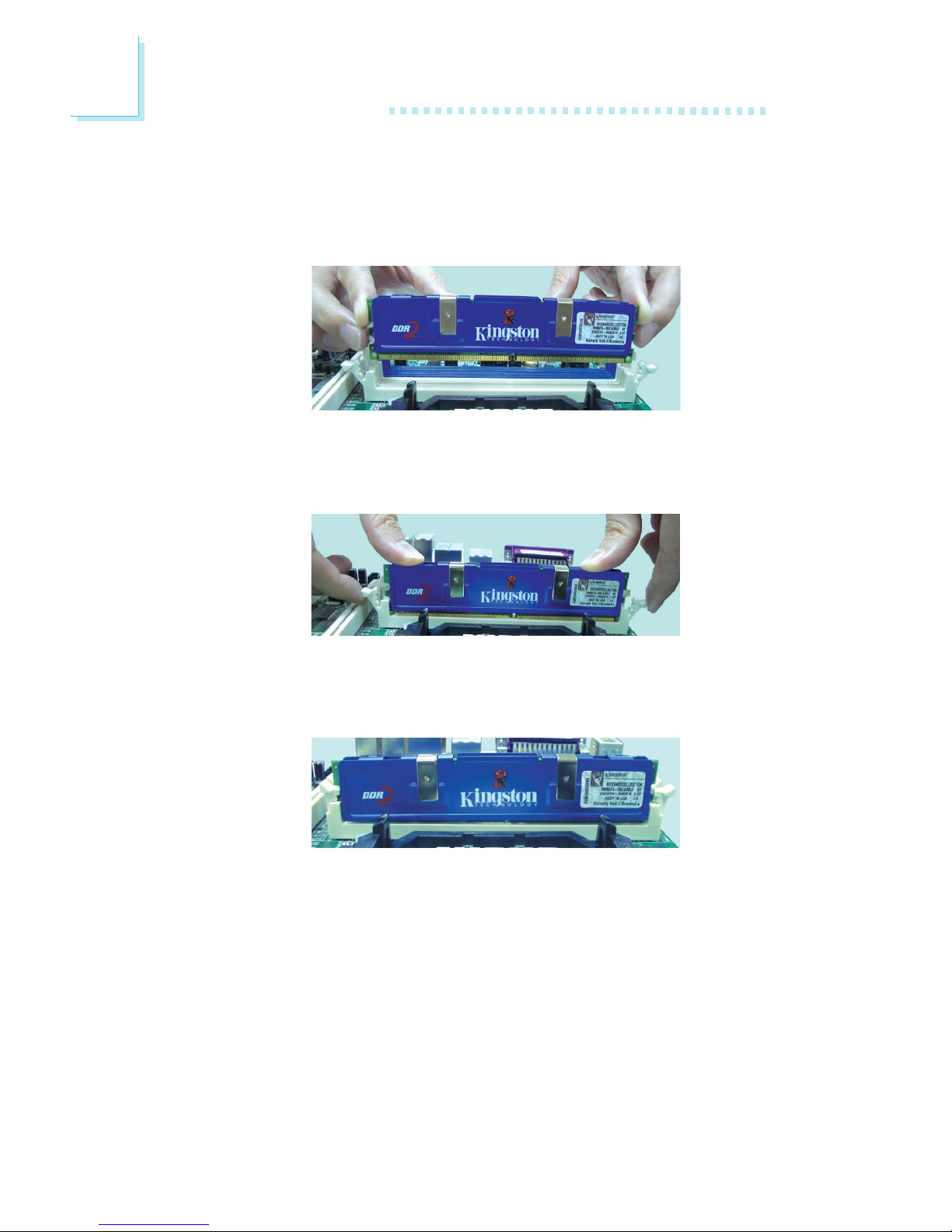
7. Seat the module vertically, pressing it down firmly until it is completely seated in the socket.
6. Grasping the module by its edges, position the module above
the socket with the “notch” in the module aligned with the “key”
on the socket. The keying mechanism ensures the module can be
plugged into the socket in only one way.
8. The ejector tabs at the ends of the socket will automatically
snap into the locked position to hold the module in place.
19
2
Hardware Installation
A
B
C
1
Intel
ICH7R
BIOS
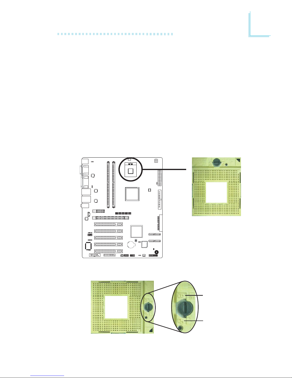
CPU
Overview
The system board is equipped with a surface mount mPGA478
CPU socket.
Installing the CPU
1. Make sure the PC and all other peripheral devices connected to
it has been powered down.
2. Disconnect all power cords and cables.
3. Locate the mPGA478 socket on the system board.
4. Use a screwdriver to turn the screw to its unlock position.
Lock
Unlock
X
20
2
Hardware Installation
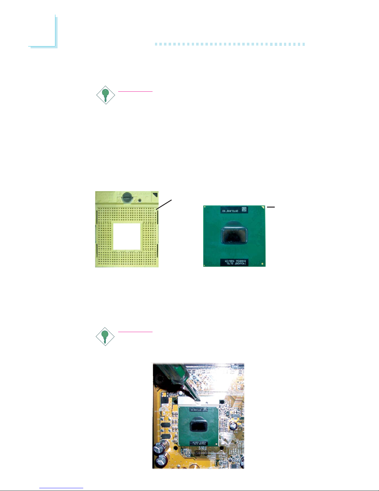
5. Position the CPU above the socket. The gold triangular mark on
the CPU must align with pin 1 of the CPU socket.
Important:
1. Only Use Intel® CoreTM Duo/Solo processor or
Intel® Celeron® M processor manufactured on
65nm technology. Intel Pentium M and Intel Celeron
M processors manufactured on 0.13 micron and 90nm
technology are not supported. Installing an incompatible
processor will cause severe damage to both the processor and system board.
2. Handle the CPU by its edges and avoid touching the
pins.
6. Insert the CPU into the socket until it is seated in place. The
CPU will fit in only one orientation and can easily be inserted
without exerting any force. Use a screwdriver to turn the screw
to its lock position.
Important:
Do not force the CPU into the socket. Forcing the CPU into
the socket may bend the pins and damage the CPU.
Gold
triangular
mark
Pin 1 of the socket
21
2
Hardware Installation
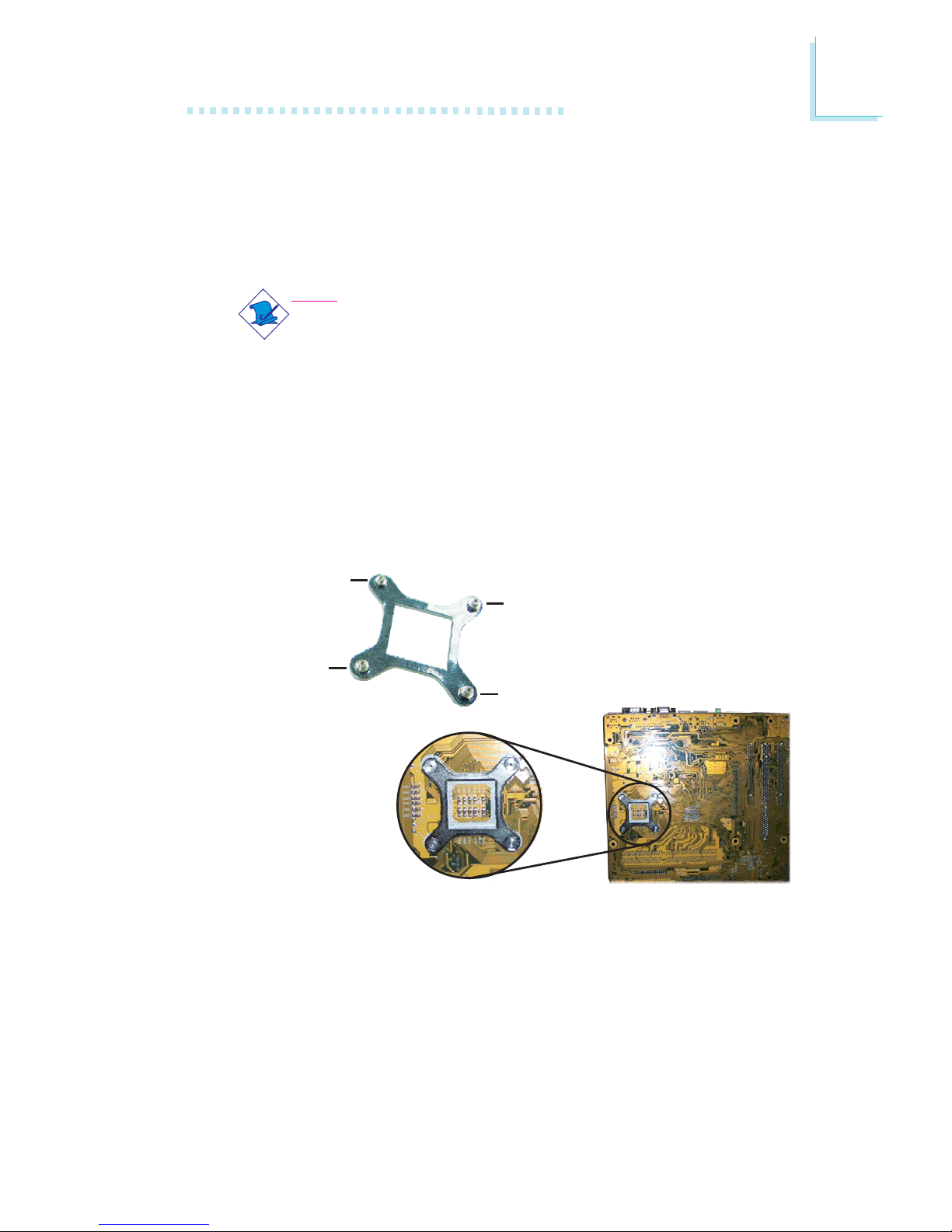
Installing the Fan and Heat Sink
The CPU must be kept cool by using a CPU fan with heat sink.
Without sufficient air circulation across the CPU and heat sink, the
CPU will overheat damaging both the CPU and system board.
Note:
• Use only certified fan and heat sink.
• Your fan and heat sink package usually contains the fan
and heat sink assembly, and an installation guide. If the installation procedure in the installation guide differs from the
one in this section, please follow the installation guide in the
package.
1. Match and insert the screw holes of the retention module base
to the mounting holes around the CPU socket from the bottom
through the top of the system board.
Screw hole
Screw hole
Screw hole
Screw hole
Buttom view of the system board
22
2
Hardware Installation
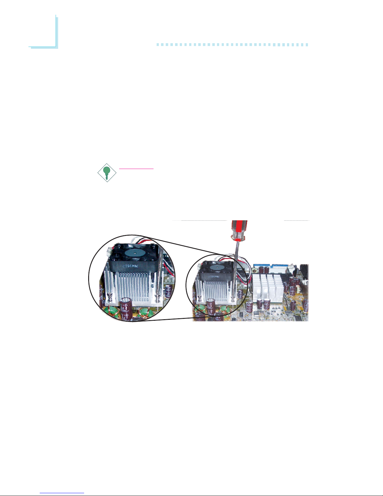
2. Place the heat sink on top of the CPU. The 4 screws around the
heat sink must match the screw holes of the retention module
base. Refer to the figure below for the correct position of the
heat sink. This is important so that the fan / heat sink will
provide adequate cooling to the components of the system
board.
Turn each Phillips head screw half way down first to initially
stabilize the heat sink onto the system board, then finally tighten
each screw.
Important:
Do not turn the first screw all the way down followed by
the next and so on. This is to avoid imbalance which might
cause cracks or fractures to the CPU and/or heat sink
assembly.
23
2
Hardware Installation
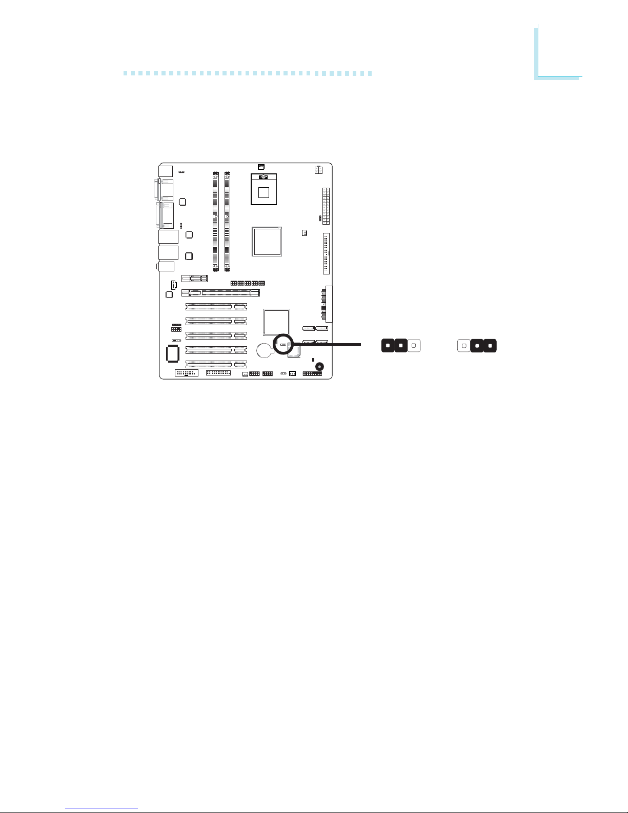
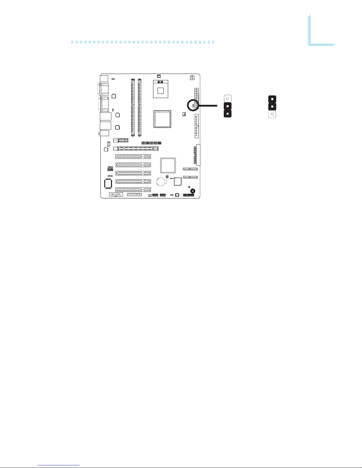
Jumper Settings
Clear CMOS Data
If you encounter the following,
a) CMOS data becomes corrupted.
b) You forgot the supervisor or user password.
you can reconfigure the system with the default values stored in the
ROM BIOS.
To load the default values stored in the ROM BIOS, please follow
the steps below.
1. Power-off the system and unplug the power cord.
2. Set JP1 pins 2 and 3 to On. Wait for a few seconds and set JP1
back to its default setting, pins 1 and 2 On.
3. Now plug the power cord and power-on the system.
A
B
C
1
Intel
ICH7R
BIOS
2-3 On:
Clear CMOS Data
1-2 On: Normal
(default)
X
JP1
312312
24
2
Hardware Installation
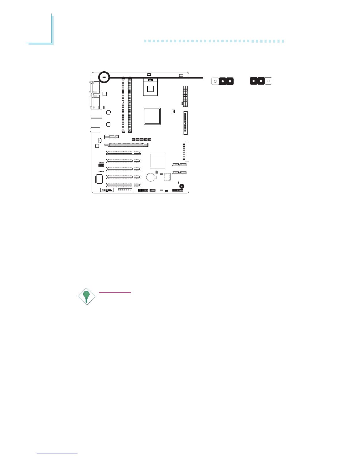
JP2 is used to select the power of the PS/2 keyboard/mouse port.
Selecting 5V_standby will allow you to use the PS/2 keyboard or
PS/2 mouse to wake up the system.
BIOS Setting
Configure the PS/2 keyboard/mouse wake up function in the Integrated Peripherals submenu (“Super IO Device” section) of the BIOS.
Refer to chapter 3 for more information.
Important:
The 5V_standby power source of your power supply must support ≥720mA.
PS/2 Power Select
A
B
C
1
Intel
ICH7R
BIOS
1-2 On: 5V
(default)
2-3 On:
5V_standby
X
JP2 312
3
1
2
25
2
Hardware Installation
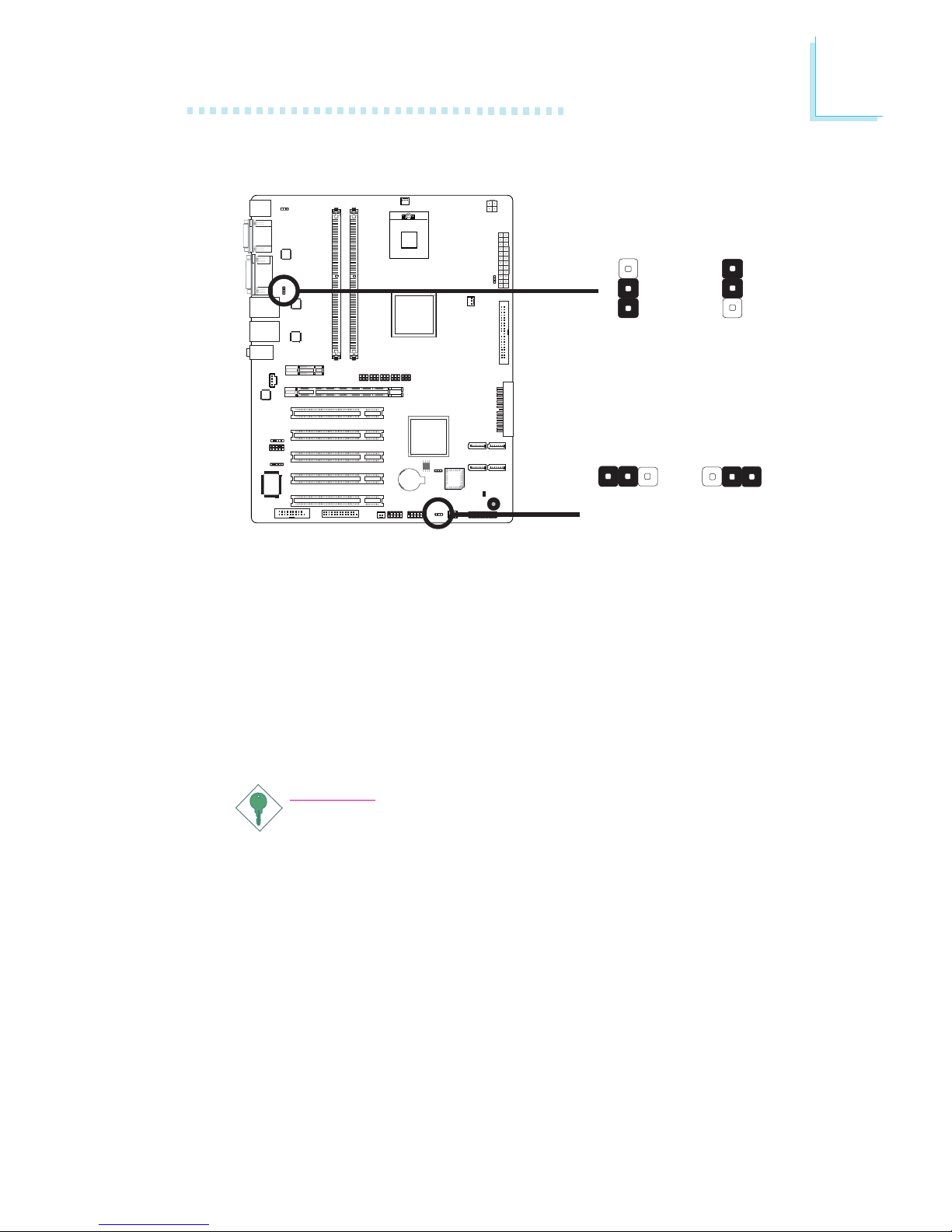
JP3 and JP4 are used to select the power of the USB ports.
Selecting 5V_standby will allow you to use the USB keyboard or
USB mouse to wake up the system.
BIOS Setting
“USB KB Wake-Up From S3” in the Power Management Setup
submenu of the BIOS must be set to Enabled. Refer to chapter 3
for more information.
Important:
If you are using the Wake-On-USB Keyboard/Mouse function for
2 USB ports, the 5V_standby power source of your power supply must support ≥1.5A. For 3 or more USB ports, the
5V_standby power source of your power supply must support
≥
2A.
USB Power Select
A
B
C
1
Intel
ICH7R
BIOS
X
USB 4-7
(JP3)
1-2 On: 5V
(default)
2-3 On:
5V_standby
X
USB 0-3
(JP4)
1-2 On: 5V
(default)
2-3 On:
5V_standby
312312
3
1
2
3
1
2
26
2
Hardware Installation
A
B
C
1
Intel
ICH7R
BIOS
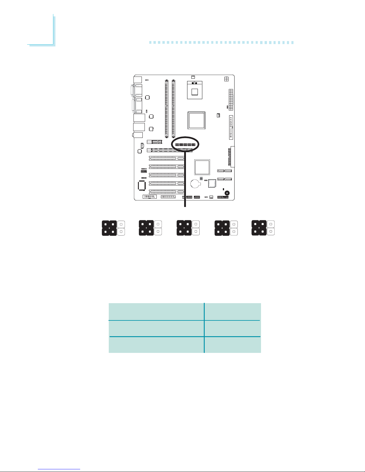
PCIE x16 / DVI Select
X
The system board allows connecting a device to either the DVI port
at the rear panel or to the PCI Express x16 card. However, you
cannot use devices connected to both the DVI port and PCI Express x16 card at the same time. Jumpers JP8 to JP12 are used to
select between using PCIE x16 or DVI.
JP8-JP12
1-2, 4-5 On
2-3, 5-6 On
PCIE x16 / DVI Select
PCIE x16
DVI
JP11
1
4
6
3
JP10
1
4
6
3
JP9
1
4
6
3
JP12
1
4
6
3
JP8
1
4
6
3
27
2
Hardware Installation
Power-on Select
JP6 is used to select the method of powering on the system. If you
want the system to power-on whenever AC power comes in, set
JP6 pins 2 and 3 to On. If you want to use the power button, set
pins 1 and 2 to On.
A
B
C
1
Intel
ICH7R
BIOS
X
JP6
2-3 On:
Power-on via
AC power
1-2 On:
Power-on via
power button
(default)
3
1
2
3
1
2
28
2
Hardware Installation
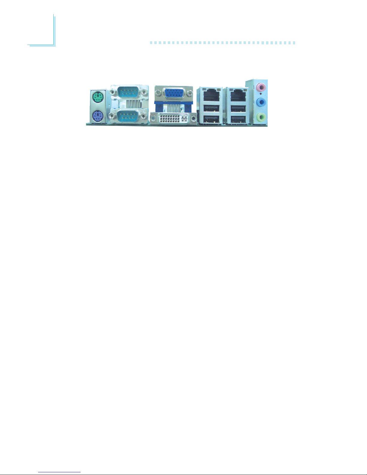
Rear Panel I/O Ports
The rear panel I/O ports consist of the following:
• PS/2 mouse port
• PS/2 keyboard port
• 2 COM ports
• VGA port
• DVI-I port
• 2 LAN ports
• 4 USB ports
• Mic-in jack
• Line-in jack
• Line-out jack
PS/2
K/B
COM 2 USB 4-5USB 6-7
VGA
Line-out
Line-in
Mic-in
PS/2
Mouse
LAN 1
COM 1
DVI-I
LAN 2
29
2
Hardware Installation
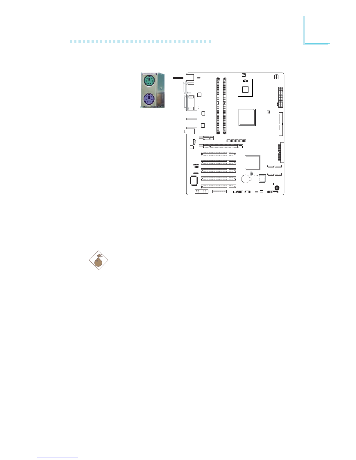
PS/2 Mouse and PS/2 Keyboard Ports
The onboard PS/2 mouse (Green) and PS/2 keyboard (Purple)
ports are at location CN1 of the system board. The PS/2 mouse
port uses IRQ12. If a mouse is not connected to this port, the
system will reserve IRQ12 for other expansion cards.
Warning:
Make sure to turn off your computer prior to connecting or
disconnecting a mouse or keyboard. Failure to do so may
damage the system board.
Wake-On-PS/2 Keyboard/Mouse
The Wake-On-PS/2 Keyboard/Mouse function allows you to use the
PS/2 keyboard or PS/2 mouse to power-on the system. To use this
function:
• Jumper Setting:
JP2 must be set to “2-3 On: 5VSB”. Refer to “PS/2 Power
Select” in this chapter for more information.
.
.
.
.
.
.
.
.
A
B
C
1
Intel
ICH7R
BIOS
W
PS/2 Mouse
PS/2 Keyboard

30
2
Hardware Installation
• BIOS Setting:
Configure the PS/2 wake up function in the Integrated Peripherals
submenu (“Super IO Device” section) of the BIOS. Refer to
chapter 3 for more information.
Important:
The 5V_standby power source of your power supply must support ≥720mA.
 Loading...