

DFI G486-EVA User Manual
G486-EVA
System Board
User’s Manual
- D23240331 -

v Copyright 1994, by DFI Inc.
All rights reserved.
No part of this document may be copied or reproduced
in any form or by any means without the prior written
consent of DFI, Inc.
DFI, Inc. makes no warranties with respect to this
documentation and disclaims any implied warranties of
merchantability, quality, or fitness for any particular
purpose. The information in this document is subject to
change without notice. DFI, Inc. reserves the right to
make revisions to this publication and to make changes
to any and/or all parts of its content, at any time,
without obligation to notify any person or entity of such
changes. Further, DFI, Inc. assumes no responsibility
for any errors that may appear in this document.
DFI is a registered trademark, and G486-EVA is a
trademark of Diamond Flower, Inc. All other product
names mentioned are trademarks or registered trademarks of their respective companies.

❖❖
❖❖
❖
FCC Statement on Class B
This equipment has been tested and found to comply
with the limits for a Class B digital device, pursuant to
Part 15 of the FCC rules. These limits are designed to
provide reasonable protection against harmful interference when the equipment is operated in a residential
installation. This equipment generates, uses, and can
radiate radio frequency energy and if not installed and
used in accordance with the instruction manual may
cause harmful interference to radio communications.
However, there is no guarantee that interference will
not occur in a particular installation. If this equipment
does cause harmful interference to radio or television
reception, which can be determined by turning the
equipment off and on, the user is encouraged to try to
correct the interference by one or more of the following
measures:
• Reorient or relocate the receiving antenna.
• Increase the separation between the equipment and
the receiver.
• Connect the equipment into an outlet on a circuit
different from that to which the receiver is connected.
• Consult the dealer or an experienced radio TV
technician for help.
Notice:
1. The changes or modification not expressly approved
by the party responsible for compliance could void
the user's authority to operate the equipment.
2. Shielded interface cables must be used in order to
comply with the emission limits.

v Table of Contents v
Introduction .................................................................................
Features and Specifications .................................................
Installation Overview .................................................................
Preparing the Area ................................................................
Handling the System Board ..................................................
Tips in Handling the System Board ...............................
Hardware Installation .............................................................
Memory Installation .........................................................
Installing the Modules ..............................................
Board Configuration ...............................................................
Jumper Settings ..............................................................
Jumper Settings for the Internal Battery ................
Jumper Settings for VL-Bus Add-on Boards .........
Jumper Settings for Light and Deep Green ...........
Cache Configuration .......................................................
Jumper Settings for Cache Memory ......................
CPU Installation and Upgrade .......................................
Jumper Settings for CPUs ......................................
Installing Upgrade CPUs ........................................
Installing the System Board ..................................................
Initial Setup Program .................................................................
Award BIOS CMOS Setup Utility ..........................................
Standard CMOS Setup ...................................................
BIOS Features Setup .....................................................
Chipset Features Setup .................................................
Power Management Setup ............................................
Load BIOS Defaults ........................................................
Load Setup Defaults .......................................................
Password Setting ............................................................
IDE HDD Auto Detection ................................................
Save and Exit Setup .......................................................
Exit Without Saving ........................................................
1-1
1-2
2-1
2-1
2-2
2-2
2-2
2-2
2-4
2-5
2-6
2-6
2-8
2-10
2-11
2-13
2-15
2-15
2-19
2-20
3-1
3-2
3-2
3-5
3-7
3-8
3-9
3-9
3-10
3-11
3-11
3-12

Troubleshooting ...........................................................................
Appendix A: Types of Modules .................................................
Appendix B: System Error Report ............................................
Appendix C: Memory and I/O Maps ..........................................
Appendix D: 16-Bit ISA I/O Pin Assignments ..........................
Appendix E: VL-Bus I/O Pin Assignments ...............................
Appendix F: Connector Pin Assignments ...............................
Appendix G: Award BIOS Hard Disk Table .............................
4-1
A-1
B-1
C-1
D-1
E-1
F-1
G-1

Energy Star Compliant System Board
1-1 u Introduction
v Introduction
The G486-EVA is an Energy Star Compliant system
board that meets the Environmental Protection Agency's
Green PC requirements. It reduces energy consumption
to 15 Watts or less by automatically turning off peripherals or the entire system, when not in use.
The G486-EVA accommodates all of the Intel 486
TM
family of CPUs. The system board may be equipped
with an 80486SX CPU running at 25/33MHz, an
80486DX CPU running at 33MHz, or an 80486DX2
CPU running at 50/66MHz. It also supports the new
Intel SL Enhanced series of CPUs.
It may also use Intel486TM DX2 OverDrive Processors,
AMD's 486DXL low power CPUs, Cyrix's Cx486DX/
DX2 or Cyrix's Cx486S/S2 CPU.
The G486-EVA uses 256Kx9, 1Mx9 and 4Mx9 SIM
modules. The memory can be configured to five different sizes from 1MB to 32MB. In addition, the
G486-EVA is equipped with three 32-bit VESA
VL-Bus, and six 16-bit and one 8-bit ISA expansion
slots.

G486-EVA
Features and Specifications
• Microprocessor
Intel 486SX-25/33, 486DX-33, 486DX2-50/66,
SL Enhanced CPUs, Intel486
TM
DX2
OverDrive Processor
AMD 486DXL low power CPU
Cyrix Cx486S-25/33, Cx486S2-50/66,
Cx486DX-25/33 and Cx486DX2-50/66
• Energy-Efficient Design
Intel SL Enhanced CPU ready
Supports system power management
Supports CPU stopped clock
Supports optional external power management
switch
Supports power saving video mode
• Chip Set
EC802G: system and cache controller
EC100: data buffer
• BIOS
Award system BIOS
• Cache Memory
128K or 256K
Supports direct map write-back or write-through
cache subsystem
• Memory Onboard
1MB to 32MB
Introduction u 1-2

Energy Star Compliant System Board
• DRAM Type
256Kx9, 1Mx9 and 4Mx9
• Slots
Three VESA VL-Bus slots
Six 16-bit ISA slots
One 8-bit ISA slot
• Power Management
Flexible Doze mode, Standby mode and Suspend
mode transitions using SMM type of CPUs and
SMM software handler.
Built-in hardware auto-transition mechanism.
Microsoft APM supported.
•PCB
4 layers
1-3 u Introduction
Package Checklist
The G486-EVA package contains the following items:
• The G486-EVA system board
• One G486-EVA user’s manual
If any of these items are missing or damaged, please
contact your dealer or sales representative for assistance.

G486-EVA
Installation Overview u 2-1
v Installation Overview
This chapter summarizes the steps in installing the
G486-EVA system board into your system unit. It also
includes a description of the area in which you must
work and directions for memory installation. Before
installing the system board, obtain the memory you plan
to install. Please refer to the memory chart on page 2-3
for the number and type of SIM modules needed for the
amount of memory you require.
Preparing the Area
Before unpacking the system board, make sure the
location you have selected is relatively free of dust and
static. Excessive exposure to dust, static electricity,
direct sunlight, excessive humidity, extreme cold and
water can damage the operational capabilities of your
system board. Avoid soft surfaces such as beds and
carpeted floors which can hinder air circulation. These
areas also attract static electricity which can damage
some circuits on your system board.
Be sure that the power source has a properly grounded,
three-pronged socket. It is essential that the power
connection be properly grounded for correct functioning
of your system board. For further protection, we recommend that you use a surge protection socket. This
will protect the system board from damage that may
result from a power surge on the line.
Move items that generate magnetic fields away from your
system board, since magnetic fields can also damage your
system board. Once you have selected the ideal location,
unpack the G486-EVA system board carefully.

Energy Star Compliant System Board
Handling the System Board
It is quite easy to inadvertently damage your system
board even before installing it in your system unit.
Static electrical discharge can damage computer components without causing any signs of physical damage. You
must take extra care in handling the system board to
ensure that no static build-up is present.
Tips in Handling the System Board
1) To prevent electrostatic build-up, leave the board in
its anti-static bag until you are ready to install it.
2) Do all preparation work on a static-free surface with
components facing up.
3) Hold the system board by its edges only. Be careful
not to touch any of the components, contacts or
connections, especially gold contacts on the board.
4) Avoid touching the pins or contacts on all modules
and connectors. Hold modules and connectors by
their edges.
Hardware Installation
Memory Installation
The G486-EVA system board can support 1MB to
32MB of memory using SIMMs. SIMM is an acronym
for Single In-line Memory Module.
2-2 u Installation Overview

G486-EVA
A SIMM consists of RAM chips soldered onto a small
circuit board. A SIMM connects to the system board
via a 30-pin card-edge connector.
The SIMM sockets are divided into two banks on the
system board. The G486-EVA system board uses
256Kx9, 1Mx9 and 4Mx9 SIM modules.
A list of approved memory brands and speeds is given in
Appendix A.
You will need 4 to 8 pieces of SIM modules, depending
on the amount of memory you intend to install. Your
system board can be configured with 1MB, 4MB, 8MB,
16MB or 32MB of onboard memory.
When installing the SIM modules, populate Bank 0 first
followed by Bank 1. Failure to do so will cause the
system board to work improperly.
The following table summarizes the bank locations and
modules needed for the corresponding memory sizes.
Each bank consists of four SIMM sockets.
Installation Overview u 2-3
Memory Size Bank 0 Bank 1
1MB 256Kx9 4MB 1Mx9 -
8MB 1Mx9 1Mx9
16MB 1Mx9 1Mx9
16MB 4Mx9 32MB 4Mx9 4Mx9
Energy Star Compliant System Board
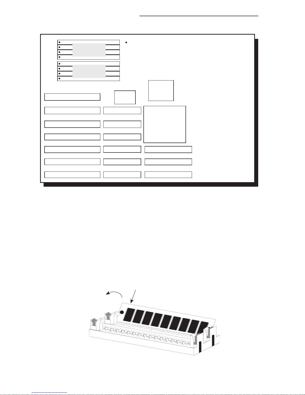
2-4 u Installation Overview
Bank 1
Bank 0
Pin 1 of the SIMM socket
Installing the Modules
SIMMs simply snap into a socket on the system board.
Pin 1 of the SIMM must correspond with Pin 1 of the
socket.
1
2
Locations of the SIMM Sockets
on the G486-EVA System Board
EC802G
EC100G
G486-EVA
Installation Overview u 2-5
1. Position the SIM module above the SIMM socket
with the chips of the module facing the center of the
system board.
2. Seat the module at an angle into the bank. Make
sure it is completely seated. Tilt the module upright
until it locks in place in the socket.
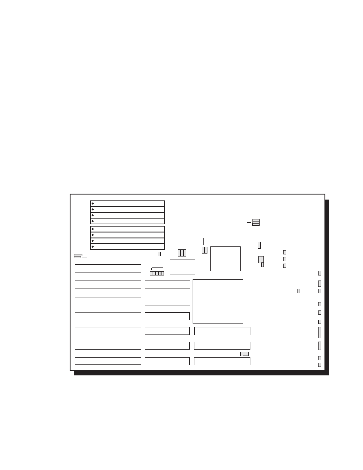
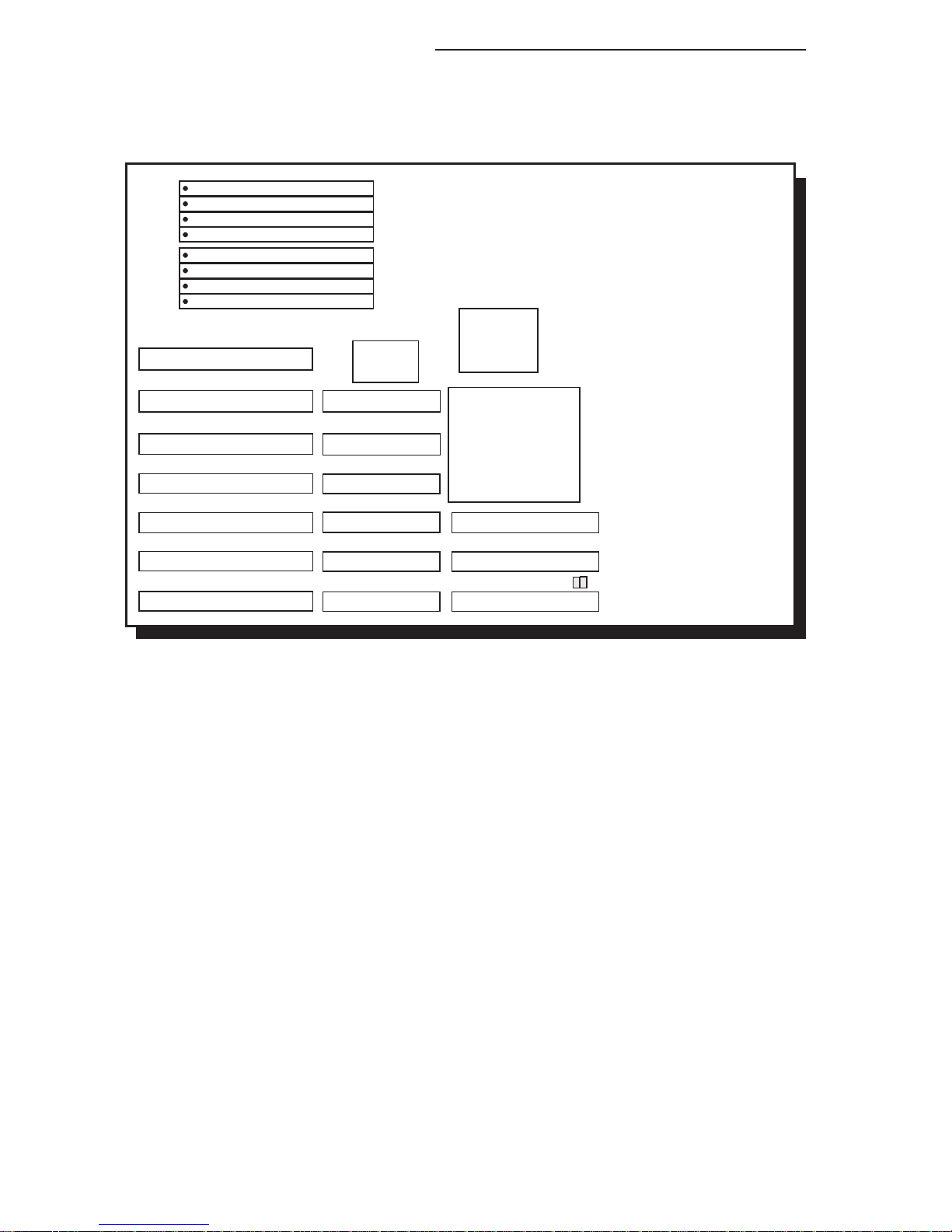
Board Configuration
The G486-EVA is designed with jumpers and connectors
onboard. Make sure that the jumpers are set correctly
before installing the system board into your system unit.
JP1
JP2
JP27
JP25
JP26
JP28
JP29 JP30
JP31
S1
S2
S3
JP47
JP46
JP43
JP42
D6
JP40
JP49
JP48
JP52
JP50
JP51
JP34, JP35, JP38
Locations of Jumpers and Connectors
on the G486-EVA System Board
EC802G
JP23
JP24
EC100G
JP21
JP22JP20
T10
JP14-JP18
Energy Star Compliant System Board
Jumper Settings
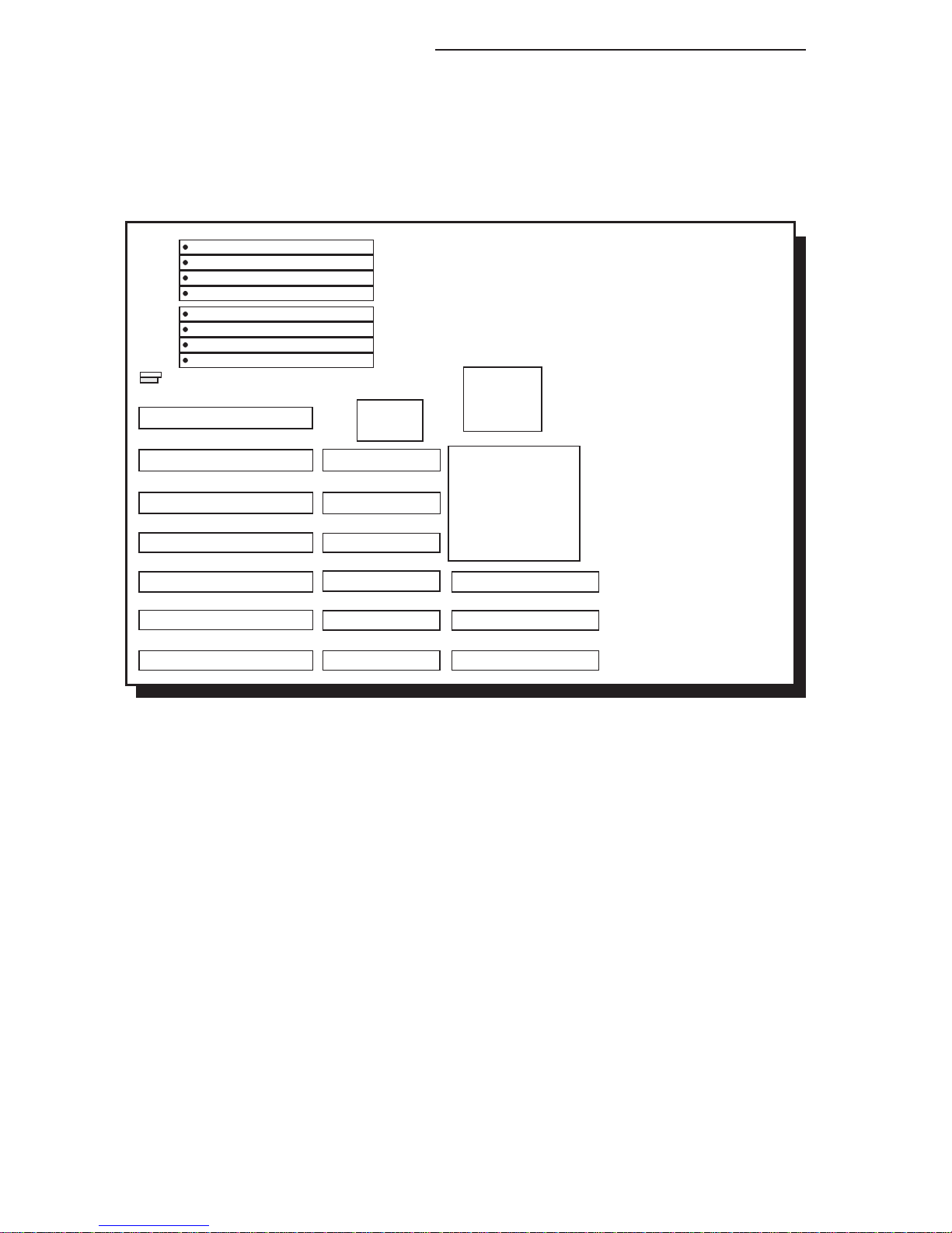
Jumper Settings for the Internal Battery
2-6 u Installation Overview
Location of Jumper JP2 on the G486-EVA System Board
JP2
EC802G
EC100G
G486-EVA
Installation Overview u 2-7
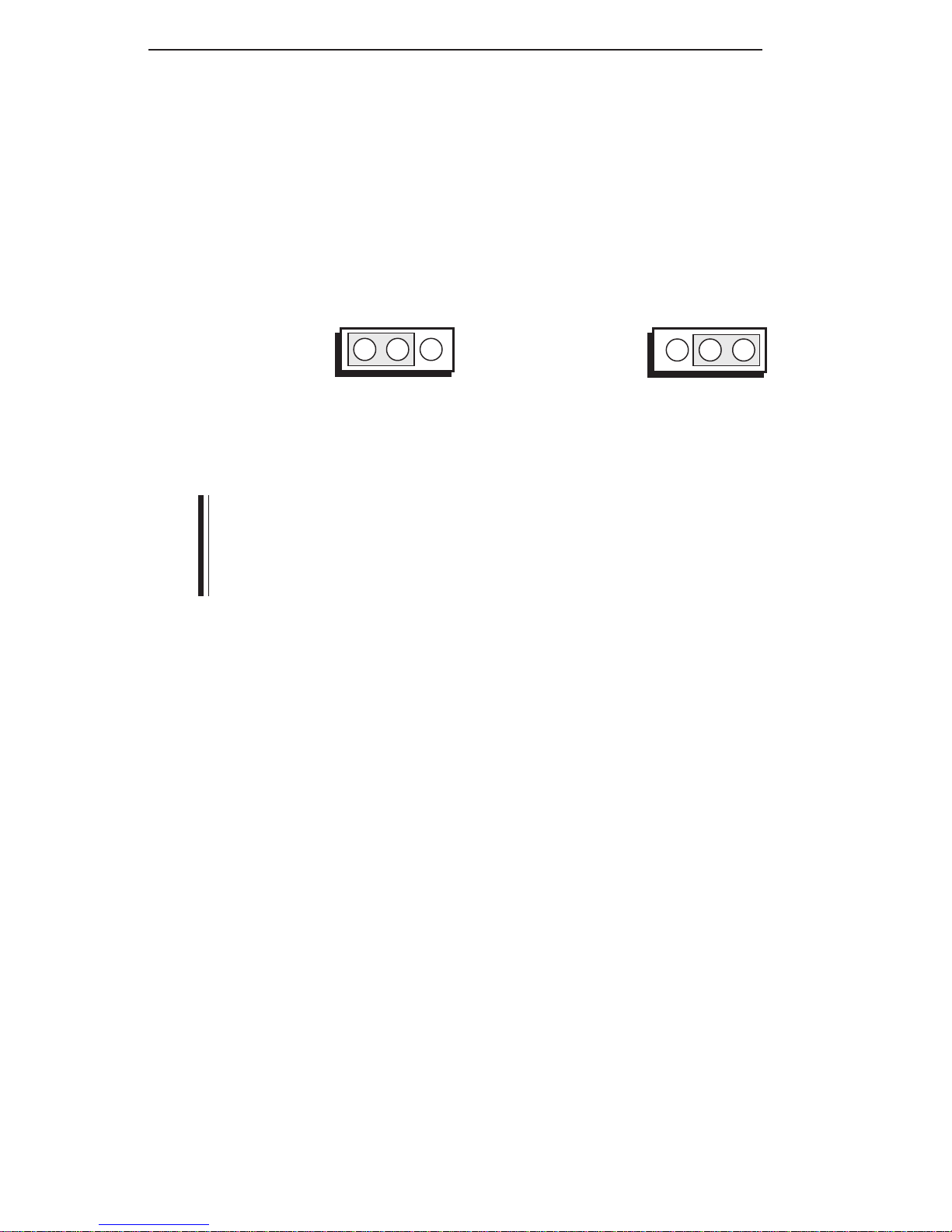
Jumper JP2
Internal Battery Select
The G486-EVA comes with an internal battery. If you
wish to install an external battery, set JP2 pins 1 and 2
to On to disable the internal battery.
321
2-3 On: Enabled
321
1-2 On: Disabled
(Default)
Note:
If you disable the internal battery, you must connect an
external battery to connector JP1 or your system will
lose its CMOS settings when powered off.
The jumpers below are for factory testing only and
should always be set to their default configuration.
Reconfiguring these jumpers will cause problems with
your G486-EVA system board.
Jumper JP14
Off: 2X BOSC (28MHz)
On: CPU CLK1 - Default
Jumper JP28
1-2 On: Default
Energy Star Compliant System Board
Jumper Settings for VL-Bus Add-on Boards
Locations of Jumpers JP34 and JP35
on the G486-EVA System Board
JP34 JP35
2-8 u Installation Overview
EC802G
EC100G
G486-EVA
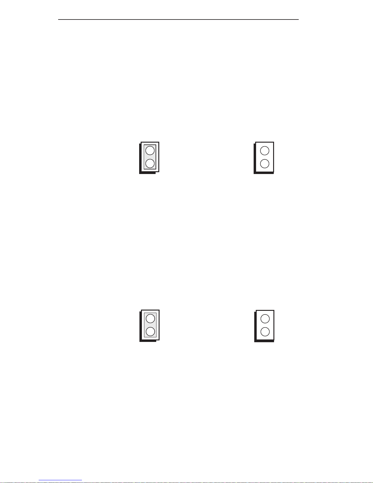
Jumper JP34
High Speed Mode for VL-Bus Board
Set Jumper JP34 to Off only if the VESA VL-Bus
add-on board(s) installed in the VL-Bus slots support
Zero Wait State. If you are not sure that your add-on
board(s) support Zero Wait State, set JP34 to On;
otherwise, a system error may occur.
On: Write One Wait State
(Default)
Off: Write Zero Wait State
Jumper JP35
CPU Speed for VL-Bus Board
If a VL-Bus board is installed in the G486-EVA system
board, Jumper JP35 must be set to On if the CPU speed
is greater than 33MHz. Set JP35 to Off if the CPU
speed is less than or equal to 33MHz.
On: CPU Speed > 33MHz
(Default)
Off: CPU Speed <= 33MHz
Installation Overview u 2-9
Energy Star Compliant System Board
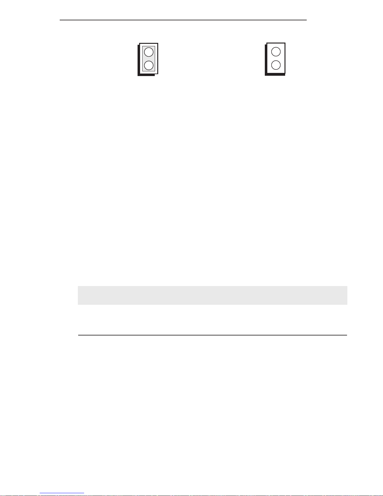
Jumper Settings for Light and Deep Green
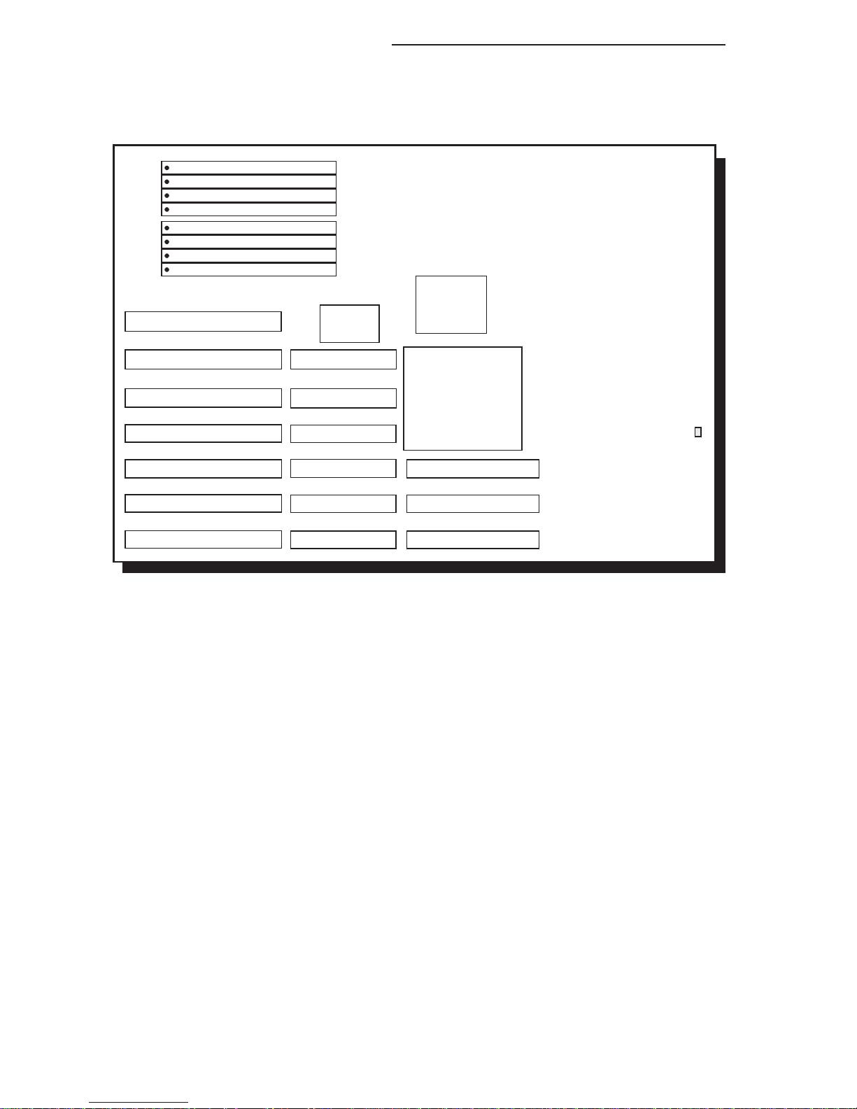
2-10 u Installation Overview
JP40
Location of Jumper JP40 on the G486-EVA System Board
Jumper JP40
Light/Deep Green Select
The different types of CPUs supported by the
G486-EVA allow you to select from two different
energy saving modes. If you have a standard Intel
486DX, SX, OverDrive Processor or AMD 486DXL,
the G486-EVA will run in light green mode. If you have
an energy saving SL Enhanced Intel 486DX or Cyrix
Cx486S/Cx486S2 CPU, then the G486-EVA will run in
deep green mode. Set Jumper JP40 according to the
type of CPU installed on the board.
EC802G
EC100G
G486-EVA
Installation Overview u 2-11
On: Light Green
486DX,486SX,
Intel486TM OverDrive
Processor, AMD 486DXL
Off: Deep Green
SL Enhanced Intel486TM DX CPU,
Cyrix Cx486S/Cx486S2
(Default)
Cache Configuration
The G486-EVA system board can be configured to two
different cache sizes: 128KB and 256KB. 128KB of
cache memory is the default size. Either four or eight
32K x 8 (20ns) SRAM chips are used for cache depending on the size of cache desired. Regardless of the
amount of cache memory installed, one 32K x 8 (20ns)
SRAM is needed for tag RAM to store the cacheable
addresses. The locations of the SRAM sockets on the
system board is shown on the next page.
Cache Size U17/U18/U19/U20 U24/U25/U26/U27 U21
128KB* 32K x 8 (20ns) None 32K x 8 (20ns)
256KB 32K x 8 (20ns) 32K x 8 (20ns) 32K x 8 (20ns)
* Default setting
 Loading...