

Page 1
1
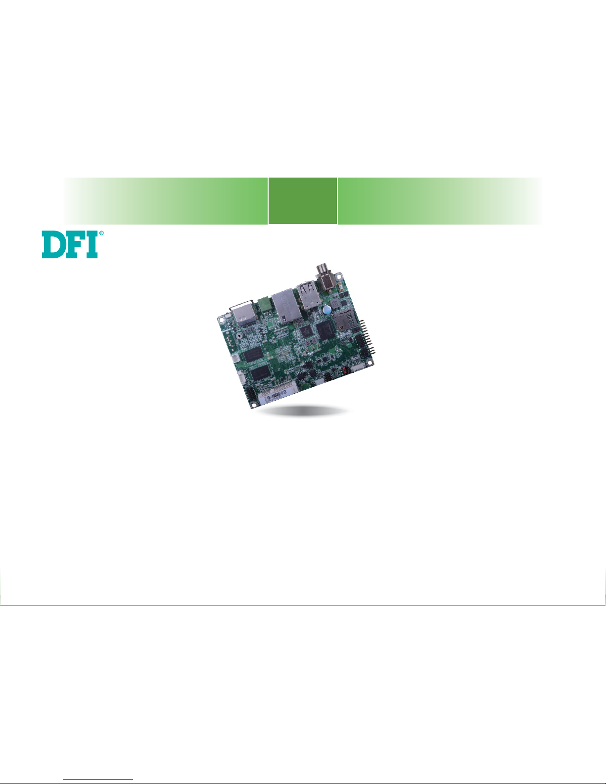
FS051
Embedded SBC 2.5”
User’s Manual
A40010835
Page 2

2
Copyright
This publication contains information that is protected by copyright. No part of it may be reproduced in any form or by any means or used to make any transformation/adaptation without
the prior written permission from the copyright holders.
This publication is provided for informational purposes only. The manufacturer makes no
representations or warranties with respect to the contents or use of this manual and specifically disclaims any express or implied warranties of merchantability or fitness for any particular
purpose. The user will assume the entire risk of the use or the results of the use of this document. Further, the manufacturer reserves the right to revise this publication and make changes
to its contents at any time, without obligation to notify any person or entity of such revisions
or changes.
Changes after the publication’s first release will be based on the product’s revision. The website
will always provide the most updated information.
© 2018. All Rights Reserved.
Trademarks
Product names or trademarks appearing in this manual are for identification purpose only and
are the properties of the respective owners.
FCC and DOC Statement on Class B
This equipment has been tested and found to comply with the limits for a Class B digital
device, pursuant to Part 15 of the FCC rules. These limits are designed to provide reasonable protection against harmful interference when the equipment is operated in a residential
installation. This equipment generates, uses and can radiate radio frequency energy and, if not
installed and used in accordance with the instruction manual, may cause harmful interference
to radio communications. However, there is no guarantee that interference will not occur in a
particular installation. If this equipment does cause harmful interference to radio or television
reception, which can be determined by turning the equipment off and on, the user is encouraged to try to correct the interference by one or more of the following measures:
• Reorient or relocate the receiving antenna.
• Increase the separation between the equipment and the receiver.
• Connect the equipment into an outlet on a circuit different from that to which the receiver
is connected.
• Consult the dealer or an experienced radio TV technician for help.
Notice:
1. The changes or modifications not expressly approved by the party responsible for compliance could void the user’s authority to operate the equipment.
2. Shielded interface cables must be used in order to comply with the emission limits.
Page 3

3
Table of Contents
Copyright ...................................................2
Trademarks ................................................2
FCC and DOC Statement on Class B ...........2
Warranty ...................................................4
Static Electricity Precautions .......................4
Safety Measures.........................................4
About the Package .....................................5
Optional Items ...........................................5
Before Using the System Board ..................5
Chapter 1 - Introduction .............................6
Specifications .................................................................. 6
Features ......................................................................... 7
Chapter 2 - Hardware Installation ............... 8
Board Layout .................................................................. 8
Block Diagram ................................................................. 9
Mechanical Diagram ........................................................ 9
System Memory .............................................................10
Jumper Settings .............................................................10
Auto Power-on Select & Panel Power Select ...................... 10
Boot Mode/Device Select ................................................ 11
I/O Ports .......................................................................12
5V DC-in ...................................................................... 12
Graphics Interface ......................................................... 13
RJ45 LAN Port ............................................................... 13
USB Ports ..................................................................... 14
Serial Port .................................................................... 14
USB OTG Port ............................................................... 15
I/O Connectors ..............................................................15
Digital I/O Connector ..................................................... 15
COM (Serial) Ports ......................................................... 16
Front Panel Connector .................................................... 17
SATA (Serial ATA) Connector (for i.MX6 Quad only) ........... 17
LVDS LCD Panel Connector ............................................. 18
Panel Backlight/SATA Power Connector ............................. 18
Expansion Slots ............................................................. 19
I
2
C Connector ............................................................... 19
Debug Connectors ......................................................... 20
CANbus Connector ......................................................... 20
Battery Connector ......................................................... 21
Chapter 3 - Software User Guide................22
Introduction ...................................................................22
Check Board Type ..........................................................22
Download Images to eMMC with MFGTool .......................22
Download Uboot Images to SPI with MFGTool .................24
Download Images to SD Card with MFGTool ....................25
Software Features ..........................................................27
General Support ............................................................ 27
Linux AP/API Support ..................................................... 27
Yocto Support ............................................................... 28
Android Support ............................................................ 29
Page 4

4
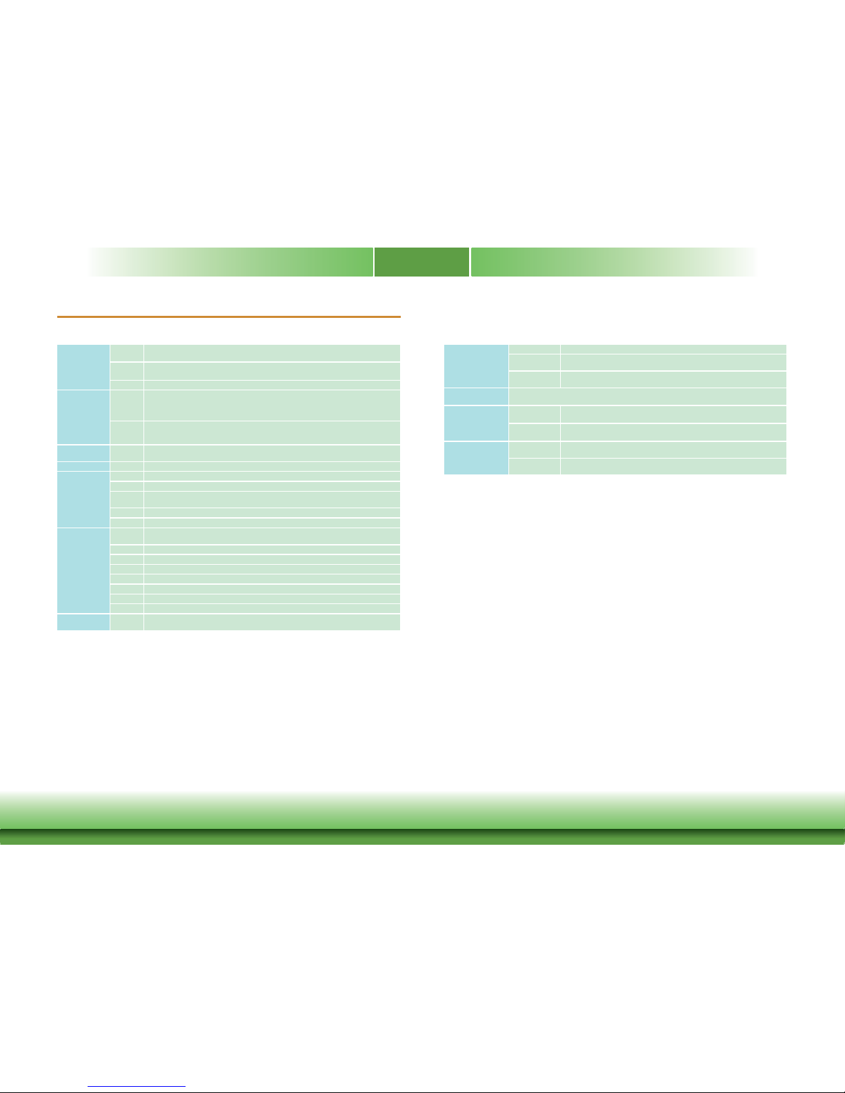
Warranty
1. Warranty does not cover damages or failures that arised from misuse of the product, inability to use the product, unauthorized replacement or alteration of components and product specifications.
2. The warranty is void if the product has been subjected to physical abuse, improper installation, modification, accidents or unauthorized repair of the product.
3. Unless otherwise instructed in this user’s manual, the user may not, under any circumstances, attempt to perform service, adjustments or repairs on the product, whether in or
out of warranty. It must be returned to the purchase point, factory or authorized service
agency for all such work.
4. We will not be liable for any indirect, special, incidental or consequential damages to the
product that has been modified or altered.
Static Electricity Precautions
It is quite easy to inadvertently damage your PC, system board, components or devices even
before installing them in your system unit. Static electrical discharge can damage computer
components without causing any signs of physical damage. You must take extra care in handling them to ensure against electrostatic build-up.
1. To prevent electrostatic build-up, leave the system board in its anti-static bag until you are
ready to install it.
2. Wear an antistatic wrist strap.
3. Do all preparation work on a static-free surface.
4. Hold the device only by its edges. Be careful not to touch any of the components, contacts
or connections.
5. Avoid touching the pins or contacts on all modules and connectors. Hold modules or connectors by their ends.
Safety Measures
To avoid damage to the system:
• Use the correct AC input voltage range.
To reduce the risk of electric shock:
• Unplug the power cord before removing the system chassis cover for installation or servicing. After installation or servicing, cover the system chassis before plugging the power
cord.
Important:
Electrostatic discharge (ESD) can damage your processor, disk drive and other components. Perform the upgrade instruction procedures described at an ESD workstation only. If such a station is not available, you can provide some ESD protection by
wearing an antistatic wrist strap and attaching it to a metal part of the system chassis. If a wrist strap is unavailable, establish and maintain contact with the system
chassis throughout any procedures requiring ESD protection.
Page 5

5
About the Package
The package contains the following items. If any of these items are missing or damaged,
please contact your dealer or sales representative for assistance.
• One FS051 board
• One terminal block for RS485
• One heat spreader (Height: 11mm)
Optional Items
• COM port cable (Length: 300mm, 2 x COM ports)
• USB 2.0 port cable (Length: 200mm, 2 x USB ports)
• Power cable for SATA and LCD backlight (Length: 155mm)
• Heat Sink (Height: 16.8mm)
The board and accessories in the package may not come similar to the information listed
above. This may differ in accordance to the sales region or models in which it was sold. For
more information about the standard package in your region, please contact your dealer or
sales representative.
Before Using the System Board
Before using the system board, prepare basic system components.
If you are installing the system board in a new system, you will need at least the following
internal components.
• Storage devices such as a SD card and hard disk drives, etc.
You will also need external system peripherals you intend to use which will normally include at
least a keyboard, a mouse and a video display monitor.
Page 6
6
Chapter 1 - Introduction
Specifi cations
Chapter 1
Chapter 1 Introduction www.dfi .com
SYSTEM Processor NXP i.MX6 Cortex-A9 DualLite, 1.0 GHz
NXP i.MX6 Cortex-A9 Quad, 1.0 GHz
Memory 1GB/2GB SDRAM Memory Down
Single Channel DDR3L 1600MHz
Flash 4MB NOR Flash
GRAPHICS Display 1 x HDMI
1 x LVDS
HDMI: resolution up to 1920x1080 @ 60Hz
LVDS: single channel, resolution up to 1366x768 @ 60Hz
Single/
Dual
Displays
Yocto: HDMI or LVDS (default)
Android: HDMI + LVDS (available upon request)
EXPANSION Interface 1 x Full-size Mini PCIe (PCIe/USB)
1 x SIM (Option)
ETHERNET Controller 1 x ATHEROS AR8033 Ethernet (10/100/1000Mbps)
I/O PORTS Ethernet 1 x GbE (RJ-45)
Serial 1 x RS-485 (2-wire)
USB 2 x USB 2.0
1 x USB 2.0 OTG Port
Display 1 x HDMI
Power 1 x Power Button
I/O
CONNECTORS
Serial 1 x RS-232 (4-wire)
1 x RS-232/422/485 (8-wire)
USB 2 x USB 2.0
Display 1 x LVDS LCD Panel Connector
SATA 1 x SATA 2.0 (up to 3Gb/s) (Quad processor only)
DIO 1 x 8-bit DIO
eMMC Supports 8GB, 16GB and 32GB eMMC onboard
SD 1 x Micro SD Slot
CANBus 1 x CANBus
WATCHDOG
TIMER
Output &
Interval
System Reset, Programmable via Software from 1 to 255 Seconds
POWER Type Single 5V +/-10% DC
Connector Terminal block (2 poles)
DC Jack (available upon request)
Consumption Typical: i.MX6:5V @ 0.460A (2.30Watt)
Max.: i.MX6:5V @ 0.963A (4.82Watt)
OS SUPPORT Yocto (1.8, default preloaded on eMMC)
Android (5.1.1)
ENVIRONMENT Temperature Operating: 0 to 60°C / -20 to 70°C
Storage: -40 to 85°C
Humidity Operating: 5 to 95% RH
Storage: 5 to 95% RH
MECHANICAL Dimensions 2.5" Pico-ITX Form Factor
100mm (3.94") x 72mm (2.83")
Height PCB: 1.6mm
Top Side: 15.5mm, Bottom Side: 4mm
Page 7

7
Chapter 1
Chapter 1 Introduction www.dfi .com
Features
• DDR3L
DDR3L SDRAM provides backward compatibility to DDR3 memory modules but can operate at
the same or at a lower power level.
• Storage
The board features SD card and eMMC memory for storing system firmware. And with the
i.MX6 Quad processor, an additional Serial ATA 2.0 port is provided for storing system and user
data.
• Gigabit LAN
The Ethernet LAN is built around the Atheros AR8033 Ethernet controller (10/100/1000Mbps).
• Power Failure Recovery
When power returns after an AC power failure, you may choose to either power on the system
manually or let the system power on automatically.
• USB
The system board supports the USB 2.0 to provide two USB host Type-A ports, one USB OTG
port and one internal pin header for two additional USB ports.
• CAN bus
The onboard CAN (Controller Area Network) connector complies with CAN Version 2.0B and
provides communication to CAN devices.
Page 8
www.dfi .com
8
Chapter 2 Hardware Installation
Chapter 2
LAN 1
Power
Button
Debug LED
USB 0-1
USB 2.0
Battery
DDR3LDDR3L
Mini
PCIe
eMMC
DC-in
1
Debug
1
9
DIO
1
6
5
2
I C
2
1
7
COM 1
HDMI
1
SATA 2.0
(fo
r i.MX6
Quad)
LCD/Inverter/SATA Power
1
5
15
Auto Power/Panel
Power Select (JP1)
10
2
JTAG
1
CANbus
USB 3-4
USB 2.0
1
10
9
2
microSD
4
4
Chapter 2 - Hardware Installation
Board Layout
Top View
Bottom View
NXP
i.MX6
Cortex-A9
Boot Mode/Device Select
(SW5)
ON
1 2 3 4 5 6 7 8
SIM
(optional)
Front
Panel
LVDS LCD Panel
1
14
15
DDR3L
DDR3L
USB OTG
1
COM 2
COM 3
19
Page 9
www.dfi .com
9
Chapter 2 Hardware Installation
Chapter 2
Block Diagram
NXP
i.MX6
DDR3L 1600MHz
Memory Down
PCIe x1
Front Panel
NOR Flash
Full-size
Mini PCIe
USB
AR8033
RGMII
RS-232/422/485
RS-232
SATA 2.0
SATA 1x
SPI
SD
SD
e.MMC
USB OTG
Digital I/O 8-bit
USB 2.0
HDMI
HDMI
LVDS
LVDS
USB 2x
I2C Bus
USB 2.0
UART TEST
USB HOST
USB2517
USB HUB
USB 2x
GLAN
RS-485
SIM(Opt.)
CANBus
CANBus
Mechanical Diagram
0
3.04
34.34
69.08
72
0
2.97
13.30
29.60
47.62
62.39
79
91.05
97.05
100
19.05
40.46
Page 10

www.dfi .com
10
Chapter 2 Hardware Installation
Chapter 2
Jumper Settings
Auto Power-on Select & Panel Power Select
JP1
System Memory
Important:
Electrostatic discharge (ESD) can damage your board, processor, disk drives, add-in
boards, and other components. Perform installation procedures at an ESD workstation
only. If such a station is not available, you can provide some ESD protection by wearing an antistatic wrist strap and attaching it to a metal part of the system chassis. If
a wrist strap is unavailable, establish and maintain contact with the system chassis
throughout any procedures requiring ESD protection.
Important:
The Debug LED lights red until the operating system is being accessed. Power-off the
PC then unplug the power cord prior to installing any devices. Failure to do so will
cause severe damage to the motherboard and components.
• 1GB/2GB SDRAM Memory Down
• Single Channel DDR3L 1600MHz
Features
DDR3L
13
5
246
13
5
246
13
5
246
1-3 On: +3.3V
(default)
3-5 On:+5V
2-4 On:
Power-on via power button
(default)
13
5
246
4-6 On:
Power-on via AC power
JP1 is used to select the method of powering on the system. If you want the system to power
on whenever AC power comes in, set JP1 pins 4 and 6 to On. If you want to use the power
button, set pins 2 and 4 to On.
When using the JP1 “Power On” feature to power the system back on after a power failure
occurs, the system may not power on if the power lost is resumed within 5 seconds (power
flicker).
JP1 is also used to select the power supplied with the LCD panel.
Important:
Before powering-on the system, make sure that the power settings of JP1 match the
LCD panel’s specification. Selecting the incorrect voltage will seriously damage the
LCD panel.
ON
1 2 3 4 5 6 7 8
DDR3L
Debug LED
Page 11

www.dfi .com
11
Chapter 2 Hardware Installation
Chapter 2
Boot Mode/Device Select
ON
1 2 3 4 5 6 7 8
1 2 3 4 5 6 7 8
SW5
1 2
1
3 4
5 6
7
8
Boot Device Select SW5
12345678
eMMC On On Off Off On On Off On
SPI xx xx xx On On Off Off On
SD On Off On Off Off On Off On
To select the boot mode and boot device, please use finger switch SW5.
Boot Mode Select SW5
Boot from the fuses 7 Off, 8 Off
Serial downloader 7 On, 8 Off
Boot from the board settings (default) 7 Off, 8 On
Reserved 7 On, 8 On
Page 12

www.dfi .com
12
Chapter 2 Hardware Installation
Chapter 2
I/O Ports
The I/O ports consist of the following:
• One 5V DC-in 2-pin terminal block or jack (optional)
• Two USB 2.0 ports
• One LAN port
• One serial (RS-485) port
• One HDMI port
• One power button
• One USB 2.0 OTG port
5V DC-in
COMDC-in
USB 2.0
LAN
HDMI
This 2-pin terminal block or jack (optional) is considered a low power solution. Connect a DC
power cord to this terminal block or jack (optional). Using a voltage more than the recommended range may fail to boot the system or cause damage to the system board.
Jack (optional)
Terminal Block
-
+
USB OTG
Power
Button
Page 13

www.dfi .com
13
Chapter 2 Hardware Installation
Chapter 2
Graphics Interface
The display port consists of the following:
• 1 HDMI port
HDMI Port
The HDMI port carries video signals and is used to connect a LCD monitor or a digital TV that
has a HDMI port.
RJ45 LAN Port
Features
• 1 RJ45 LAN port provided by Atheros AR8033 Ethernet controller (10/100/1000Mbps)
The LAN port enables the system board to connect to a local area network with a network
hub.
LAN 1
HDMI
Page 14

www.dfi .com
14
Chapter 2 Hardware Installation
Chapter 2
USB Ports
The USB device allows data exchange between your computer and a wide range of simultaneously accessible external Plug and Play peripherals.
The system board is equipped with 2 onboard USB 2.0 ports (USB 0-1). The 10-pin connector
allows you to connect 2 additional USB 2.0 ports (USB 3-4). The additional USB ports may be
mounted on a card-edge bracket. Install the card-edge bracket to an available slot at the rear
of the system chassis and then insert the USB port cables to a connector.
USB 2.0
USB 1
USB 0
1
2
10
VCC
-Data0
+Data0
GND
VCC
-Data1
+Data1
GND
NC
USB 3-4
USB 2.0
Serial Port
The serial port provides 2-wire RS485 communication with support of auto flow control.
1 2
COM
Pin Pin Name Pin Pin Name
1
RS485+
2
RS485-
Page 15

www.dfi .com
15
Chapter 2 Hardware Installation
Chapter 2
ON
1 2 3 4 5 6 7 8
USB OTG
The USB OTG (USB 2.0) port is used for USB communication.
The Digital I/O connector supports 8-bit digital input/output signals to provide powering-on
function of the connected devices.
Pin Pin Name
1
DIO7
2
DIO6
3
DIO5
4
DIO4
5
DIO3
6
DIO2
7
DIO1
8
DIO0
9
5V
10
GND
USB OTG Port
Digital I/O
1
2
9
10
I/O Connectors
Digital I/O Connector
Page 16

www.dfi .com
16
Chapter 2 Hardware Installation
Chapter 2
COM (Serial) Ports
ON
1 2 3 4 5 6 7 8
COM 2: RS232
COM 3: RS232/422/485
COM 2COM 3
COM 2 is fixed at RS232 whereas COM 3 can be selected among RS232, RS422 and RS485.
RS485 communication supports auto flow control.
The serial ports are asynchronous communication ports with 16C550A-compatible UARTs that
can be used with modems, serial printers, remote display terminals, and other serial devices.
Pins RS-232
1
NC
2
NC
3
RX
4
RTS
5
TX
6
CTS
7
NC
8
NC
9
NC
10
NC
Pins RS-232 Full RS-422 RS-485
11
MDCD2- TX_B R(B)/T(B)
12
MDSR2- NC NC
13
MSIN2- TX_A R(A)/T(A)
14
MRTS2- NC NC
15
MSO2- RX_A NC
16
MCTS2- NC NC
17
MDTR2- RX_B NC
18
MRI2- NC NC
19
GND NC NC
20
NC NC NC
1
2
19
20
COM 2 Connector COM 3 Connector
Page 17

www.dfi .com
17
Chapter 2 Hardware Installation
Chapter 2
SATA (Serial ATA) Connector (for i.MX6 Quad only)
• 1 Serial ATA 2.0 port with data transfer rate up to 3Gb/s
The Serial ATA connector is used to connect the Serial ATA device. Connect one end of the Se-
rial ATA data cable to a SATA connector and the other end to your Serial ATA device.
Features
SATA
7
RXM
GND
TXP
TXM
GND
1
RXP
GND
Front Panel Connector
ON
1 2 3 4 5 6 7 8
Front
Panel
Power Button
This switch is used to power on or off the system.
Reset Button
This switch allows you to reboot without having to power off the system.
Power_LED
This LED indicates power status.
1
3
24
6
5
Pin Pin Name Pin Pin Name
1
Power Button
2
Power_LED
3
GND
4
NC
5
Reset Button
6
NC
Page 18

www.dfi .com
18
Chapter 2 Hardware Installation
Chapter 2
LVDS LCD Panel Connector
Panel Backlight/SATA Power Connector
The system board allows you to connect a LCD Display Panel by means of the LVDS LCD panel
connector and the Panel Backlight/SATA power connector. These connectors transmit video signals and power from the system board to the LCD Display Panel. Panel Backlight/SATA power
connector also supplies power to the SATA drive. Connect one end of the provided power
cable to the SATA power connector and the other end to your storage device.
Refer to the right side for the pin functions of these connectors.
Pin Pin Name Pin Pin Name
1
GND
2
GND
3
LVDS_CLK-
4
LVDS_CLK+
5
LVDS_Out3-
6
LVDS_Out3+
7
LVDS_Out2-
8
LVDS_Out2+
9
LVDS_Out1-
10
LVDS_Out1+
11
LVDS_Out0-
12
LVDS_Out0+
13
Panel Power
14
Panel Power
Pin Pin Name
1
Panel Backlight/SATA Power (+5V)
2
GND
3
Panel Backlight On/Off Control
4
Dimming Control
5
Panel Backlight/SATA Power (+5V)
LVDS LCD Panel
1
14
Panel Backlight/SATA Power
5
1
ON
1 2 3 4 5 6 7 8
LVDS LCD Panel Connector Panel Backlight/SATA Power Connector
Note:
1. DFI board's LVDS connector:
Manufacturer: E-call
Part No: 0110-3221140
Description: Wafer connector, 14 pin, 1.25mm (pitch), White, 3.45mm (height), SMT
type, 90 degree
2. DFI board's Panel Backlight/SATA power connector:
Manufacturer: E-call
Part No: 0110-3221050
Description: Wafer connector, 5 pin, 1.25mm (pitch), 3.45mm (height), SMT type,
90 degree, White
3. DFI board's LVDS cable:
Manufacturer: Molex
Part No: 51021-1400
Description: 1.25mm (pitch)
Page 19

www.dfi .com
19
Chapter 2 Hardware Installation
Chapter 2
The I2C connector is used to monitor or communicate with system components.
I2C Connector
I2C
1
2
5
Pin Pin Name
1
3.3V
2
GND
3
I2C_Clock
4
I2C_ALERT-
5
I2C_DATA
Expansion Slots
Mini PCI Express Slot
The full-size Mini PCIe socket supports PCIe x1 signals and is used to install a Mini PCIe card.
SIM Slot (optional)
The SIM slot on the system board is used to insert a SIM card and can be used in conjunction
with the Mini PCI Express slot to provide mobile communication capability.
microSD Socket
The microSD socket allows you to install a microSD card for the expansion of available storage.
Mini PCIe
SIM Slot (optional)
ON
1 2 3 4 5 6 7 8
microSD
Page 20

www.dfi .com
20
Chapter 2 Hardware Installation
Chapter 2
CANbus Connector
The CAN bus (Controller Area Network) connector is used for interconnecting electronic control
units (ECUs).
CANbus
1
Pin Pin Name
1
3.3V
2
CAN1_H
3
CAN1_L
4
CAN1_GND
Debug Connectors
The JTAG and debug connectors are used for debugging purposes.
JTAG
Debug
Pin Pin Name
1
3.3V
2
UART5_RX
3
UART5_TX
4
GND
1
2
9
10
1
Pin Pin Name Pin Pin Name
1
3.3V
2
JTAG_TMS
3
GND
4
JTAG_TCK
5
GND
6
JTAG_TDO
7
JTAG_MOD
8
JTAG_TDI
9
JTAG_nTRST
10
JTAG_nRESET
JTAG ConnectorDebug Connector
Page 21

www.dfi .com
21
Chapter 2 Hardware Installation
Chapter 2
Battery Connector
The lithium ion battery powers the real-time clock. It is an auxiliary source of power when the
main power is shut off.
Safety Measures
• Danger of explosion if battery incorrectly replaced.
• Replace only with the same or equivalent type recommended by the manufacturer.
• Dispose of used batteries according to local ordinance
.
Connect to the
battery connector
Battery
Battery
Connector
1
+3.3V
GND
2
Page 22

www.dfi .com
22
Chapter 3 Software User Guide
Chapter 3
Chapter 3 - Software User Guide
Introduction
FS051 platform is an embedded system with Yocto 1.8 preloaded on eMMC. Demo images are
supported under Yocto 1.8 and Android 5.1.1 environment.
Check Board Type
You will execute different files according to the CPU types. This section explains how to identify
the boards with i.MX6 DualLite CPU and i.MX6 Quad CPU.
Download Images to eMMC with MFGTool
1. Set the finger switch SW5 to “Serial Downloader Mode”: pins 7 on and 8 off.
ON
1 2 3 4 5 6 7 8
FS051 DualLite FS051 QuadSW5 SW5
2. Plug in the Micro USB cable to your PC and power-on the FS051.
Important:
The adapter output voltage is 5V for FS051.
+
-
Micro USB Cable
Page 23

www.dfi .com
23
Chapter 3 Software User Guide
Chapter 3
3. Unzip Image package on your PC.
4. Yocto image: execute “\\[core type]\
yocto-emmc-fs051-[core type]-all.vbs”.
For example, for DualLite CPU, execute “\\DualLite_core\yocto-emmc-fs051-DualLite-all.vbs”.
Android image: execute “\\[core type]\
android-emmc-fs051-[core type]-all.vbs”.
For example, for DualLite CPU, execute
“\\DualLite_core\android-emmc-fs051-DualLite-all.vbs”.
5. You will see the device connected as “HID-compliant device.”
6. After all preparation is done, click “Start” to burn the file. Wait until the process ends.
7. After the burning is done, click “Stop” and turn the power off.
8. Set the finger switch SW5 to the “eMMC Start Mode”: pins 1, 2, 5, 6, 8 on and 3, 4, 7 off.
ON
1 2 3 4 5 6 7 8
9. Power-on the device again to reboot it into the system.
Page 24

www.dfi .com
24
Chapter 3 Software User Guide
Chapter 3
Download Uboot Images to SPI with MFGTool
1. First complete above “Download Images to eMMC with MFGTool” steps.
2. Set the finger switch SW5 to “Serial Downloader Mode”: pins 7 on and 8 off.
4. Unzip Image package on your PC.
5. Yocto image: execute “\\[core type]\
yocto-spi-fs051_[core type]-u-boot.vbs”.
For example, for DualLite CPU, execute “\\DualLite_core\yocto-spi-fs051_DualLite-u-boot.vbs”.
Android image: execute “\\[core type]\
android-spi-fs051_[core type]-u-boot.vbs”.
For example, for DualLite CPU, execute
“\\DualLite_core\android-spi-fs051_DualLite-u-boot.vbs”.
6. You will see the device connected as “HID-compliant device.”
7. After all preparation is done, click “Start” to burn the file. Wait until the process ends.
3. Plug in the Micro USB cable to your PC and power-on the FS051.
Important:
The adapter output voltage is 5V for FS051.
ON
1 2 3 4 5 6 7 8
+
-
Micro USB Cable
Page 25

www.dfi .com
25
Chapter 3 Software User Guide
Chapter 3
8. After the burning is done, click “Stop” and turn the power off.
9. Set the finger switch SW5 to the “SPI Start Mode”: pins 4, 5, 8 on and 6, 7 off.
ON
1 2 3 4 5 6 7 8
Download Images to SD Card with MFGTool
1. Set the finger switch SW5 to “SD Card Download Mode”: pins 1, 3, 6, 7 on and 2, 4, 5,
8 off.
ON
1 2 3 4 5 6 7 8
2. Plug in the Micro USB cable to your PC and power-on the FS051.
Important:
1. The adapter output voltage is 5V for FS051.
2. Do not insert SD card before turning on the device power.
10. Power-on the device again to reboot it into the system.
+
-
Micro USB Cable
Page 26

www.dfi .com
26
Chapter 3 Software User Guide
Chapter 3
5. You will see the device connected as “HID-compliant device.”
6. Insert SD card.
3. Unzip Image package on your PC.
4. Yocto image: execute “\\[core type]\SDBoot\
yocto-sdcard-fs051-[core type]-all.vbs”.
For example, for Quad CPU, execute “\\Quad_core\SDBoot\yocto-sdcard-fs051-Quad-all.vbs”.
Android image: execute “\\[core type]\SDBoot\
android-sdcard-fs051-[core type]-all.vbs”.
For example, for Quad CPU, execute
“\\Quad_core\SDBoot\android-sdcard-fs051-Quad-all.vbs”.
7. After all preparation is done, click “Start” to burn the file. Wait until the process ends.
8. After the burning is done, click “Stop” and turn the power off.
SD Card
Page 27

www.dfi .com
27
Chapter 3 Software User Guide
Chapter 3
9. Set the finger switch SW5 to the “SD Card Start Mode”: pins 1, 3, 6, 8 on and 2, 4, 5, 7
off.
ON
1 2 3 4 5 6 7 8
10. Power-on the device again to reboot it into the system.
Software Features
General Support
(*) is depended on the NXP support.
Component Name Base-Line Feature
General
OS Support
Yocto 1.8 - Kernel 3.14.52 (default preloaded on eMMC)
Android 5.1.1 - Kernel 3.14.52
Misc
Firmware Upgrade (*) MFGTool fi rmware update tool
Utilities (*) Hardware diagnostic utilities
Linux AP/API Support
(*) is depended on the NXP support.
Component Description Detail
Linux
Yocto 1.8 - Kernel 3.14.52
It is an open-source project that delivers a
set of tools which create operating system
images for embedded Linux systems.
Support X-11 Demo Image Only (*)
Linux
AP/API
NXP i.MX6 Yocto 1.8 BSP
Support X11 Window
Support BitBake build tool
All library and utility should support (*).
Source code package (support by request)
Support I
2
C, Watchdog, GPIO,
LVDS brightness control
Provide support console for i.MX6 platform
Android
Android 5.1.1 - Kernel 3.14.52 Support Demo Image
Android
AP/API
NXP i.MX6 Android 5.1.1 NXP BSP
Support Android AOSP launcher
Support Android ADB shell
Support Android APK install
All library, utility and Android apk should
support (*).
Source code package (support by request)
Support I
2
C, Watchdog, GPIO,
LVDS brightness control
Provide support console for i.MX6 platform.
Page 28

www.dfi .com
28
Chapter 3 Software User Guide
Chapter 3
Yocto Support
(*) is depended on the NXP support.
Component Support Status
Yocto Version
1.8
Kernel Version
3.14.52
Window System
X11 without QT5 build
eMMC
Support eMMC boot, eMMC v5.1, Linux ext3 fi le system
Ethernet LAN1
Support "ping", "ifconfi g" console commands verify, static IP/DHCP
Dynamic IP, fi xed MAC address
USB 2.0
1. Support USB HID Keyboard and Mouse Device
2. Support USB Mass Storage by "mount" console command, EXT3/EXT4/
FAT fi lesystem
USB OTG
1. Support USB HID Keyboard and Mouse Device
2. Support USB Mass Storage by "mount" console command, EXT3/EXT4/
FAT fi lesystem
3. Support connect to PC to update image by i.MX6 MFGTool
LVDS Panel
Support single display function, resolution 1024x600, RGB24
LVDS Backlight
Support control by Linux device node, level value 0~7
HDMI Video
Output
Support single display function, need to plug in HDMI cable before power
on, resolution 1920x1080@60
DIO
Support read input voltage, set outpout voltage high/low status, control
by Linux device node, 8 pins
Micro SD Card
(SD Slot)
1. Support SD card boot, support SD storage by "mount" console
command, FAT fi lesystem. (Support Kingston, micro SDHC 4GB class 4,
4GB/16GB)
2. For standard product, we do not port any SDIO module.
Mini PCIe
1. Support "lspci" console command for check PCIe card status.
2. For standard product, we only port ENLi AP12356 WiFi/BT module.
SATA (Quad)
1. Support mSATA storage only (by "mount" console command, EXT3/
EXT4/FAT fi lesystem).
2. For standard product, we do not port any mSATA module.
SIM Slot
N/A. For standard product, we do not port any 3G/4G phone module.
Component Support Status
UART1 - RS232
Support Loopback & fl ow control test, BR 115200 (need DFI Linux user
space utility)
UART1 - RS485
Support Loopback test, BR 115200 (need DFI Linux user space utility)
UART1 - RS422
Support Loopback test, BR 115200 (need DFI Linux user space utility)
UART2 - RS485
Support Loopback test, BR 115200 (need DFI Linux user space utility)
UART4 - RS232
Support Loopback & fl ow control test, BR 115200 (need DFI Linux user
space utility)
SPI2 Nor-Flash
Support SPI2 Nor-Flash boot (Uboot image only)
RTC
Support linux "date -s" and "hwclock -w" console commands to set system
time
Thermal Sensor
Support read device temperature (degrees C) by Linux device node
Debug Serial
Port
Suport read Linux kernel debug log by serial port, use PC serial terminal
tool (ex. PuTTY), BR 115200
CAN Bus
Support "cansend", "candump" console commands for test send/read data
Play Video
Support play MPEG4 fi le (need DFI Linux user space utility).
Watchdog
Support NXP utility "wdt_driver_test.out"(*) to test Watchdog reboot
function
Package
Manager
N/A. For standard product, we do not build in package manager.
Page 29

www.dfi .com
29
Chapter 3 Software User Guide
Chapter 3
Android Support
(*) is depended on the NXP support.
Component Support Status
Android Version
5.1.1
Kernel Version
3.14.52
eMMC
Support eMMC boot, eMMC v5.1, Linux ext4 fi le system
Ethernet LAN1
1. Support "ping", "ifconfi g" console commands, and NXP Ethernet APP (*)
2. Support static IP/DHCP Dynamic IP, fi xed MAC address
USB 2.0
1. Support USB HID Keyboard and Mouse Device
2. Support Android auto mount USB Mass Storage function (only one USB
storage is available at a time. If second USB is plugged-in the USB cable,
second USB is not available. If fi rst USB is unplugged, second USB needs
to be unplugged and re-plugged back to be available.) FAT32 fi lesystem
only without multi-partition
USB OTG
1. Support USB HID Keyboard and Mouse Device
2. Support Android auto mount USB Mass Storage function (only one USB
storage is available at a time. If second USB is plugged-in the USB cable,
second USB is not available. If fi rst USB is unplugged, second USB needs
to be unplugged and re-plugged back to be available.) FAT32 fi lesystem
only without multi-partition
3. Support connect to PC to update image by i.MX6 MFGTool
LVDS Panel
1. Support LVDS+HDMI dual display function. LVDS is main output,
resolution 1024x600, RGB24
2. For Android standard product, we enable dual display function by
default.
LVDS Backlight
1. Support Android->Settings->Display->Brightness level control without
adaptive brightness function.
2. For standard product, we do not port any light sensor module.
HDMI Video
Output
1. Default support LVDS+HDMI dual display function. HDMI is slave
output, resolution 1024x600 (based on LVDS resolution).
2. If users want to change HDMI resolution (i.e. 1920x1080), users need
to modify kernel parameter to change LVDS resolution to 1920x1080 too.
3. For Android standard product, we enable dual display function by
default.
DIO
1. Support read input voltage, set outpout voltage high/low status, control
by Linux device node, 8 pins
2. Support DFI Android GPIO demo APP (support by request)
Component Support Status
Micro SD Card
(SD Slot)
1. Support SD card boot, support SD storage by "mount" console
command, FAT32 fi lesystem. (Support Kingston, micro SDHC 4GB class 4,
4GB/16GB)
2. Support Android auto mount SD card function (FAT32 fi lesystem only,
without multi-partition)
3. For standard product, we do not port any SDIO module.
Mini PCIe
1. Support "busybox lspci" console command for check PCIe card status.
2. For standard product, we only port ENLi AP12356 WiFi/BT module.
SATA (Quad)
1. Support mSATA hard disk storage only
2. Support Android auto mount SATA function (FAT32 fi lesystem only,
without multi-partition)
3. For standard product, we do not port any mSATA module.
SIM Slot
N/A. For standard product, we do not port any 3G/4G phone module.
UART1 - RS232
Support Loopback & fl ow control test, BR 115200 by DFI Android UART
demo APP (supoprt by request)
UART1 - RS485
Support Loopback test, BR 115200 by DFI Android UART demo APP
(supoprt by request)
UART1 - RS422
Support Loopback test, BR 115200 by DFI Android UART demo APP
(supoprt by request)
UART2 - RS485
Support Loopback test, BR 115200 by DFI Android UART demo APP
(supoprt by request)
UART4 - RS232
Support Loopback & fl ow control test, BR 115200 by DFI Android UART
demo APP (supoprt by request)
SPI2 Nor-Flash
Support SPI2 Nor-Flash boot (Uboot image only)
RTC
Support Android->Settings->Date to set system time function.
Thermal Sensor
Support read device temperature (degrees C) by Android CPU-Z APP
installed by user
Debug Serial
Port
Suport read Linux kernel debug log by serial port, use PC serial terminal
tool (ex. PuTTY), BR 115200
CAN Bus
Support "cansend", "candump" console commands for test send/read data
Play Video
Support play MPEG4 fi le by Android AOSP Gallery APP.
Watchdog
Support adb shell command "am hang --allow-restart" to test Watchdog
reboot function
Page 30

www.dfi .com
30
Chapter 3 Software User Guide
Chapter 3
Component Support Status
WiFi/BT
1. Support AP12356 WiFi/BT module
2. AP12356 WiFi:
(1) Support WiFi STA Mode (connect WiFi AP) by Android UI to enable/
disable it.
(2) Support Soft AP Mode (enable DHCP/IPv4 routing) by Android UI to
enable/disable it.
(3) Support Android UI to set up Soft AP information
(4) Support Android Airplane mode to disable WiFi function
(5) Not support STA mode and Soft AP mode enable at the same time
(6) Not support other WiFi modes, i.e. Wi-Fi Direct, Miracast, Wi-Fi
TimeSYnc, etc.
(7) STA mode limitation: when plug-in wired LAN, STA mode will
disconnect automatically by Android network framework limitation
3. AP12356 BT:
(1) Support BT connected and enable/disable by Android UI
(2) Support BT fi les transfer by OPP profi le using "Bluetooth File
Transfer" tool.
(3) Support OPP, FTP, OBEX, SDAP profi le only
(4) Not support other BT profi les which are not listed above
(5) Suppot Android Airplane mode to disable BT function
Android Build
Type
ENG Build without SELinux
Android ADB
Support
Android Factory
Reset
Support
Android
Fastboot
Not support
Android OTA
Not support
Android CTS
Not support
Android GMS/
GTS
Not support
Android Suspend
Not support suspend, set never to suspend by default. The power
key supports suspend function on FS051 device.
Component Support Status
Preload Android
APPs
1. AOSP Browser: Web Browser
2. AOSP Calculator: Calculator APP
3. AOSP Calendar: Calendar APP
4. AOSP Clock: Clock APP, support alarm wake-up
5. AOSP Contacts: function not ready, preload for 3G module test in the
future
6. AOSP Dev Tools: develop test tool
7. AOSP Downloads: show downloads APP
8. AOSP Email: E-Mail APP
9. AOSP Gallery: Gallery APP (JPEG)
10. AOSP Messaging: Short Message Service (SMS) APP. Function not
ready, preload for 3G module test in the future.
11. AOSP Music: Play music APP (MP3)
12. AOSP Phone: function not ready, preload for 3G module test in the
future.
13. AOSP Settings: Android Settings APP
14. AOSP Sound Recorder: Sound Recorder APP. Function not ready,
preload for AOSP Audio module test in the future
15. NXP Audio Route (*): function not ready, preload for Audio module
test in the future.
16. NXP Ethernet (*): Ethernet settings APP.
17. Open-source Simple Explorer: File Explorer APP
 Loading...