

Page 1
ES520-CD Installation Guide
Package Contents
•
1 ES520-CD system unit
•
1 Power adapter: 60W
•
1 Quick Installation Guide
•
1 CD disk includes:
- Drivers / Manual
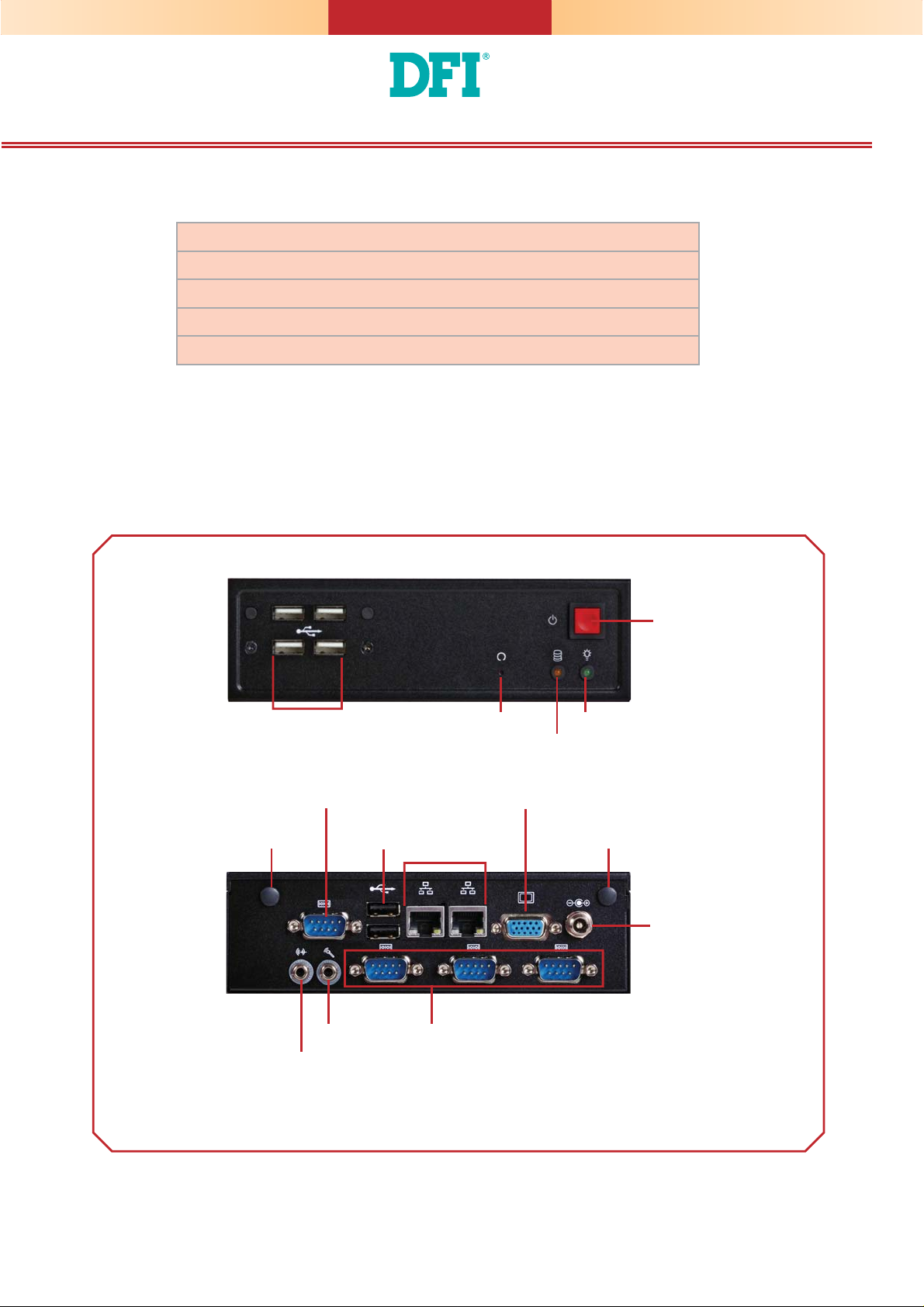
Panel
USB 2.0
Wi-Fi Module
Antenna Hole
Line-out
COM
Mic-in
USB 2.0
Reset
Front View
LAN
COM (optional)
Power
Power LED
HDD LED
VGA
Wi-Fi Module
Antenna Hole
DC-in
Rear View
DFI reserves the right to change the specifi cations at any time prior to the product's release. For the latest revision and for a more
details of the installation process, please refer to the user's manual on the website.
www.dfi .com
1
Page 2
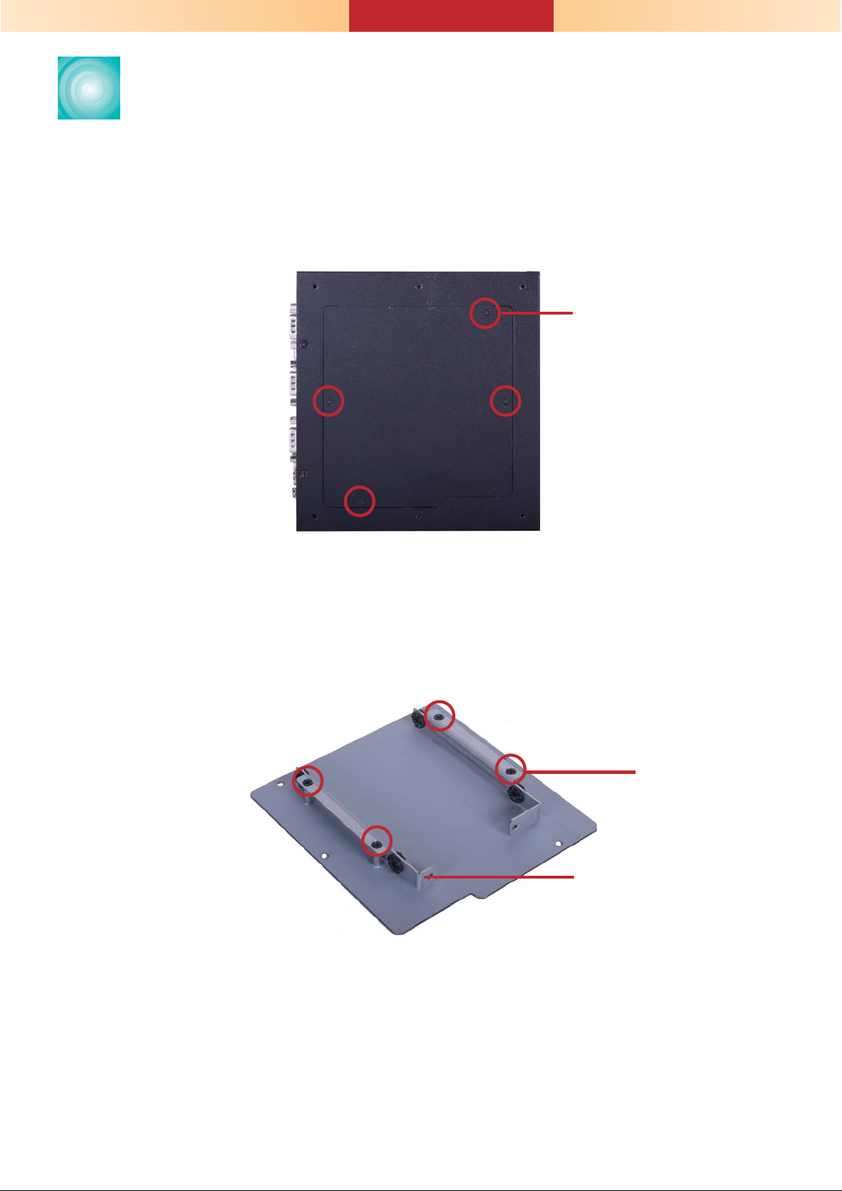
Installing a 2.5" SATA Drive
1. Remove the 4 mounting screws to open the cover on the bottom
of the system.
Mounting screw
2. Fasten the 4 mounting screws that secure the HDD brackets fi rmly
to the system cover.
Mounting screw
HDD bracket
2
Page 3

3. Align the mounting holes of the SATA drive with the mounting
holes on the HDD brackets and then use the provided mounting
screws to secure the drive in place.
Mounting screw
HDD bracket
SATA drive
Mounting screw
3
Page 4

4. Connect the SATA data cable and the SATA power cable to the
connectors on the SATA drive.
SATA power
cable
SATA data
cable
5. After completing steps above, fasten the cover with 4 mounting
screws.
Mounting screw
4
Page 5

Board Layout and Jumper Settings
Front Panel
1
10
Front Audio
USB 2-5 Power
Seletct (JP6)
1
USB 2.0
COM 1
USB 2-3
9
9
USB 4-5
USB 0-1
USB 2.0
LAN 1
9
1
SATA Power
1
2
1
2
1
1
2
COM2
1
RS232/422/485
2
Select (JP3)
USB 0-1 Power
Select (JP4)
COM2
COM5
2
1
System Fan
COM3
1
10
9
9
1
10
9
9
COM4
6
5
1
1
2
1
2
1
COM6
10
2
SPI Flash BIOS
10
1
Battery
Clear
CMOS (JP7)
10
9
11
1
12
Chassis Intrusion
Standby Power
LED
Panel Power
Select (JP2)
Intel
NM10
1
1
2
DIO Power
Fintek
F81866
Mini PCIe/mSATA Select (JP8)
6
125
LVDS Panel
Select (SW2)
LVDS LCD
ON
DIO
SATA 0
1
Panel
8
12
10
1
3
5
39
40
4
CompactFlash
Socket
Intel
WG82574L
LAN 2
VGA
Power-on Select
(JP5)
DC-in
1
Intel
WG82574L
Intel Atom
D2550/ N2800/
N2600
DDR3 SODIMM
LCD/ Inverter
TOP
Power-on Select JP5
Power-on via power button
(default)
Auto power-on 2-3 On
LVDS Panel Select Channel SW2
800x600 6/18 bit Single 1-4 On
1024x768 6/18 bit Single 2-4 On, 1 Off
1024x768 8/24 bit Single 1,3,4 On, 2 Off
1280X768 6/18 bit Single 3-4 On, 1-2 Off
1280X800 6/18 bit Single 1,2,4 On, 3 Off
1280X960 6/18 bit Single 2,4 On, 1,3 Off
1280X1024 8/24 bit Dual 1,4 On, 2,3 Off
1366X768 6/18 bit Single 4 On, 1-3 Off
1366X768 8/24 bit Single 1-3 On, 4 Off
1440X900 8/24 bit Dual 2-3 On, 1,4 Off
1400X1050 8/24 bit Dual 1,3 On, 2,4 Off
1600X900 8/24 bit Dual 3 On, 1,2,4 Off
1680X1050 8/24 bit Dual 1-2 On, 3-4 Off
1600X1200 8/24 bit Dual 2 On, 1,3,4 Off
1920X1080 8/24 bit Dual 1 On, 2-4 Off
1920X1200 8/24 bit Dual 1-4 Off
1-2 On
1
2
1
8
Power
CPU Fan
1
BOTTOM
Panel Power Select JP2
+12V 1-2 On
+5V 3-4 On
+3.3V (default) 5-6 On
USB Power: 0-1 (JP4)/ 2-5 (JP6)
+5V (default) 1-2 On
+5V_standby 2-3 On
Clear CMOS JP7
Normal (default) 1-2 On
Clear CMOS 2-3 On
COM 2 RS232/RS422/
RS485 Select
RS232 (default) 1-2 On
RS422 Full Duplex 3-4 On
RS485 5-6 On
Mini PCIe/mSATA Select JP8
Mini PCIe (default) 1-4-7-10 On
mSATA 2-5-8-10 On
Mini PCIe
JP3
2-5-8-11 On
3-6-9-12 On
www.dfi .com
5
934-ES520D-0A0G
A34101438
 Loading...