

Page 1
EC800 Series Installation Guide
Package Contents
•
1 EC800 system unit
•
1 Power adapter: 60W
•
6 mounting screws for Mini PCIe module
•
1 Quick Installation Guide
•
1 CD disk includes:
- Drivers / Manual
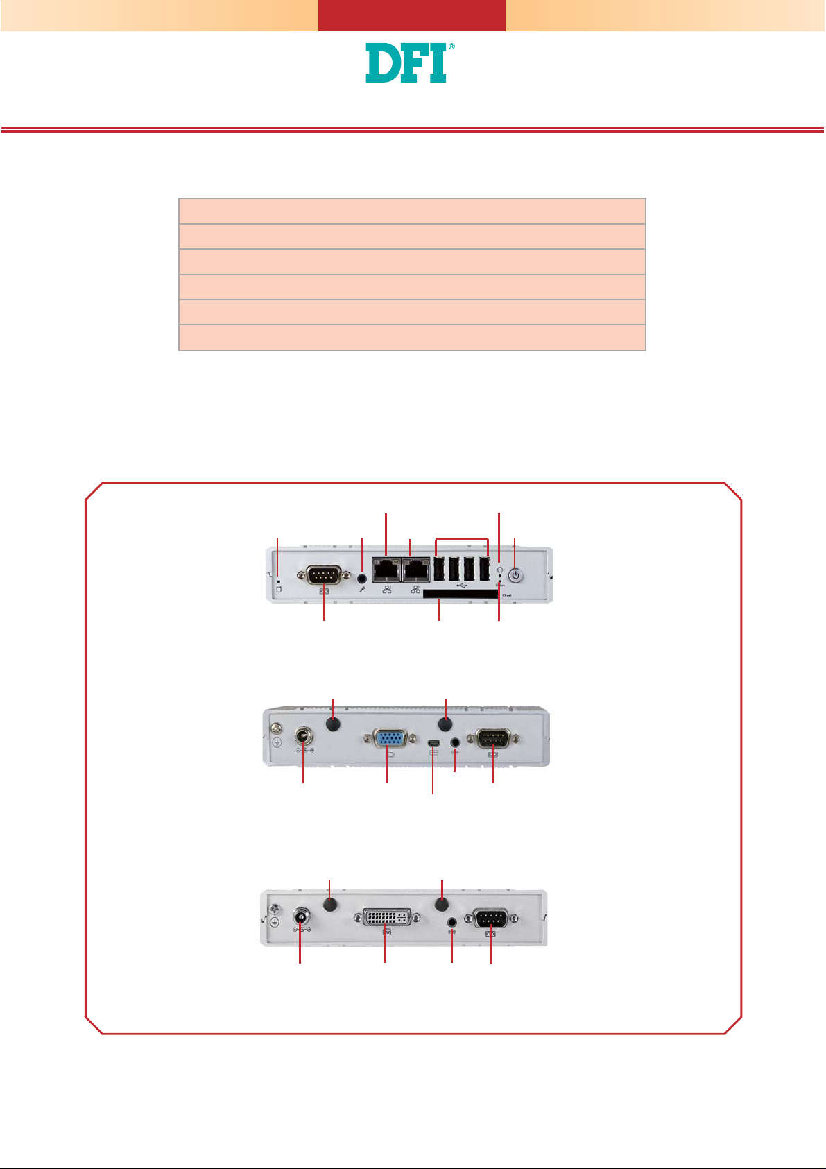
Panel
HDD LED
LAN 2
USB
CFast Status LED
COM 1
Mic-in
LAN 1
Front View
Wi-Fi/3G
Antenna
VGA9~24V DC-in COM 2
Wi-Fi/3G
Antenna
Line-out
micro HDMI
Dual Display Rear View
Wi-Fi/3G
Antenna
Wi-Fi/3G
Antenna
Reset
Power
DVI-I9~24V DC-in COM 2/
Line-out
Isolated 4-bit DIO
Single Display Rear View
DFI reserves the right to change the specifi cations at any time prior to the product's release. For the latest revision and for a
more details of the installation process, please refer to the user's manual on the website.
www.dfi .com
1
Page 2
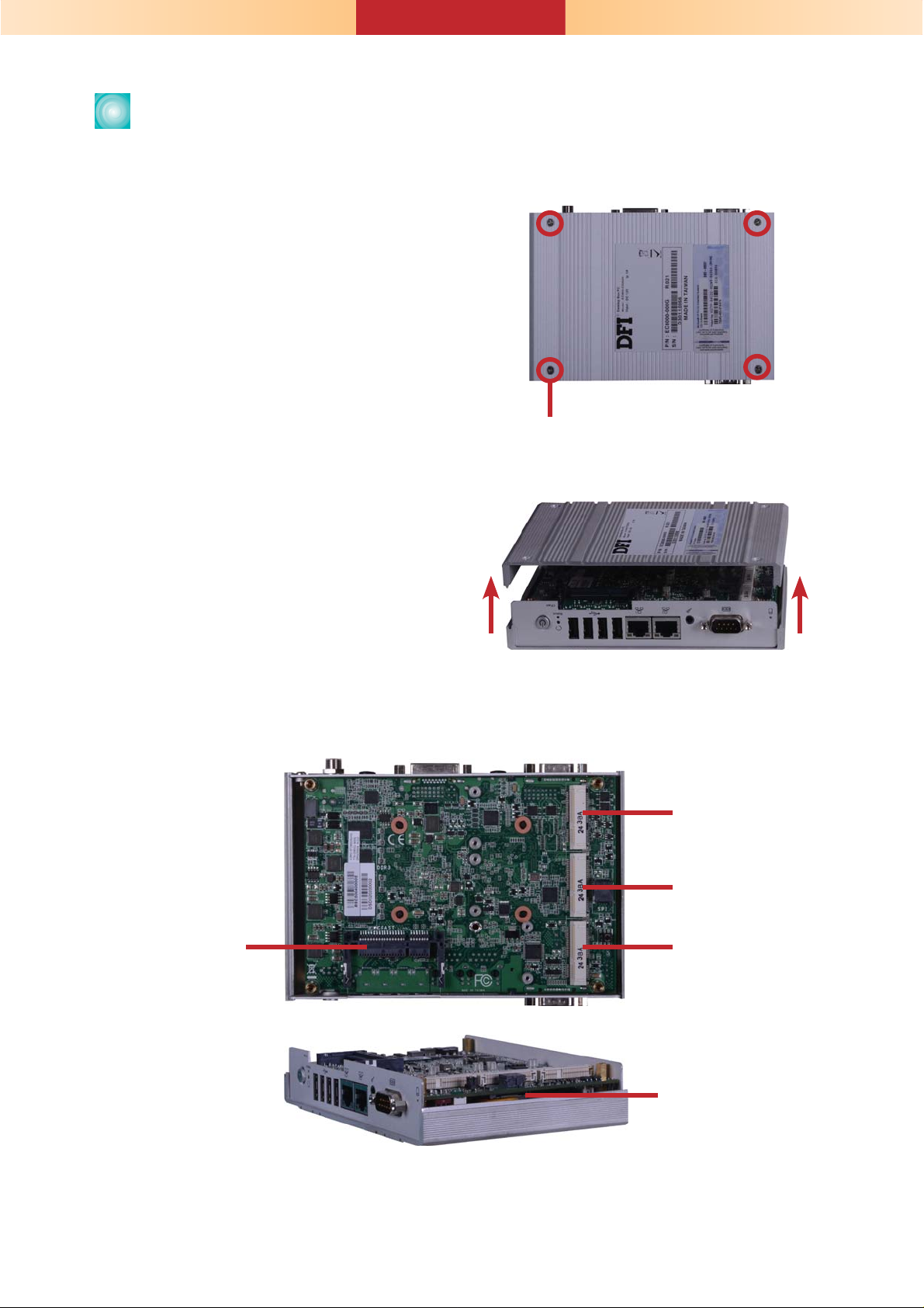
Removing the Chassis Cover
1. Make sure the system and all other peripheral devices connected to it has been poweredoff.
2. Disconnect all power cords and cables.
3. The 4 mounting screws on the bottom side
(labeled side) of the system are used to
secure the cover to the chassis. Remove
these screws and then put them in a safe
place for later use.
Mounting Screw
4. After removing the mounting screws, lift the
cover up.
5. The CFast socket, and Mini PCIe/mSATA slot are readily accessible after removing the chassis
cover. And the SIM slot is also accessible at the side of the system board.
Lift the Cover Upward
PCIe x1, USB,
3G signal
mSATA
CFast Socket
PCIe x1, USB,
Wi-Fi signal
SIM slot
2
Page 3

Installing a Mini PCIe and/or mSATA Card
1. Locate the Mini PCIe slot on the system
board.
2. The system board is equipped with 2 Mini
PCIe slots. The Mini PCIe slot supports full
length and half length Mini PCIe card. Note
the key on the slot. The key ensures the
Mini PCIe card can be plugged into the slot
in only one direction.
3. Grasping the Mini PCIe card by its
edges, align the card into the slot at an
approximately 30 degrees angle. Apply
fi rm even pressure to each end of the card
until it slips down into the slot. The contact
fi ngers on the edge of the card will almost
completely disappear inside the slot.
PCIe x1, USB,
3G signal
PCIe x1, USB,
Wi-Fi signal
Full length
Half length
PCIe x1, USB, and 3G
signals
4. Push the Mini PCIe card down and use the
provided mounting screws to secure the
card on the system board.
PCIe x1, USB, and
Wi-Fi signals
Mounting Screw
3
Page 4

Board Layout and Jumper Settings
1
System fan
HDD_LED
COM 1
LAN 1
LAN 2
USB 0
1
Battery
3
F81866
Mic-in
1
Buzzer
Intel
WG82574L
Intel
WG82574L
SIM Card slot
COM 2/ DIO Select (JP10)
COM 2/ DIO Select (JP9)
Intel
NM10
Intel Atom
Fintek
Chassis Intrusion
20
12
12
3101
VGA
DIO
21
19
10
13
Line-out
HDMI
DVI-I/VGA
1
COM 2/
Isolated 4-bit DIO
DVI-I
/
VGA
Mini PCIe 1 mSATA
Asmedia
ASM1442
SPI Flash BIOS
ICS
9VRS4339
1
2
Power-on/ CMOS
Select (JP5)
56
Mini PCIe 2
Realtek
ALC886
CFast
USB 1
USB 2
Standby_LED
USB 3
Power
2
USB 0-3/ 4-5
Power Select (JP8)
12
Reset
USB 4-5
561
10
D2550/ N2800/
N2600
DDR3 DDR3 DDR3
DDR3
DC-IN
Intersil
ISL95831
DDR3
DDR3
DDR3 DDR3
TOP BOTTOM
Power-on/ Clear CMOS Select JP5
Power-on via power button (default) 1-3 On
Auto power-on 3-5 On
Normal (default) 2-4 On
Clear CMOS 4-6 On
USB Power Select (JP8) USB 0-1 USB 2-5
+5V 2-4 On 1-3 On
+5V_standby (default) 4-6 On 3-5 On
COM2/ DIO Select JP9 and JP10
COM2 (default) 1-4-7-10 On
2-5-8-11 On
DIO 2-5-8-11 On
3-6-9-12 On
Note:
You cannot use COM2 and DIO at the same time. Please set up JP9 and JP10 at the same time.
Note:
The CD that came with the system contains an autorun screen to install drivers, utilities,
and software applications required to enhance the performance of the system and a user's
manual for your reference. Insert the CD into a CD-ROM drive. The autorun screen will
appear. If after inserting the CD, “Autorun” did not automatically start, please go directly to
the root directory of the CD and double-click “Setup”. Please install all required drivers.
934-EC8000-0B0G
A26054441
4
 Loading...