

Page 1
EC700-BT Installation Guide
Package Contents
•
1 EC700-BT system unit
•
Mounting screws for SATA drive
•
Mounting screws for Mini PCIe module
•
1 Quick Installation Guide
•
1 CD disk includes:
- Drivers / Manual
Note:
The CD that came with the system contains an autorun screen to install drivers, utilities, and software
applications required to enhance the performance of the system and a user's manual for your reference.
Insert the CD into a CD-ROM drive. The autorun screen will appear. If after inserting the CD, “Autorun”
did not automatically start, please go directly to the root directory of the CD and double-click “Setup”.
Please install all required drivers.
DFI reserves the right to change the specifi cations at any time prior to the product's release. For the latest revision and for more details
of the installation process, please refer to the user's manual on the website.
www.dfi .com
1
Page 2
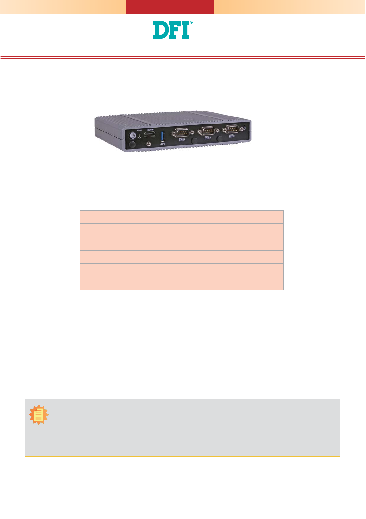
Installing a 2.5" SATA Drive
1. Locate the SATA drive bay on the system board. Unplug the SATA power and data cable, and
remove the 4 mounting screws that secure the drive bay to the system board.
SATA data cable
SATA drive bay
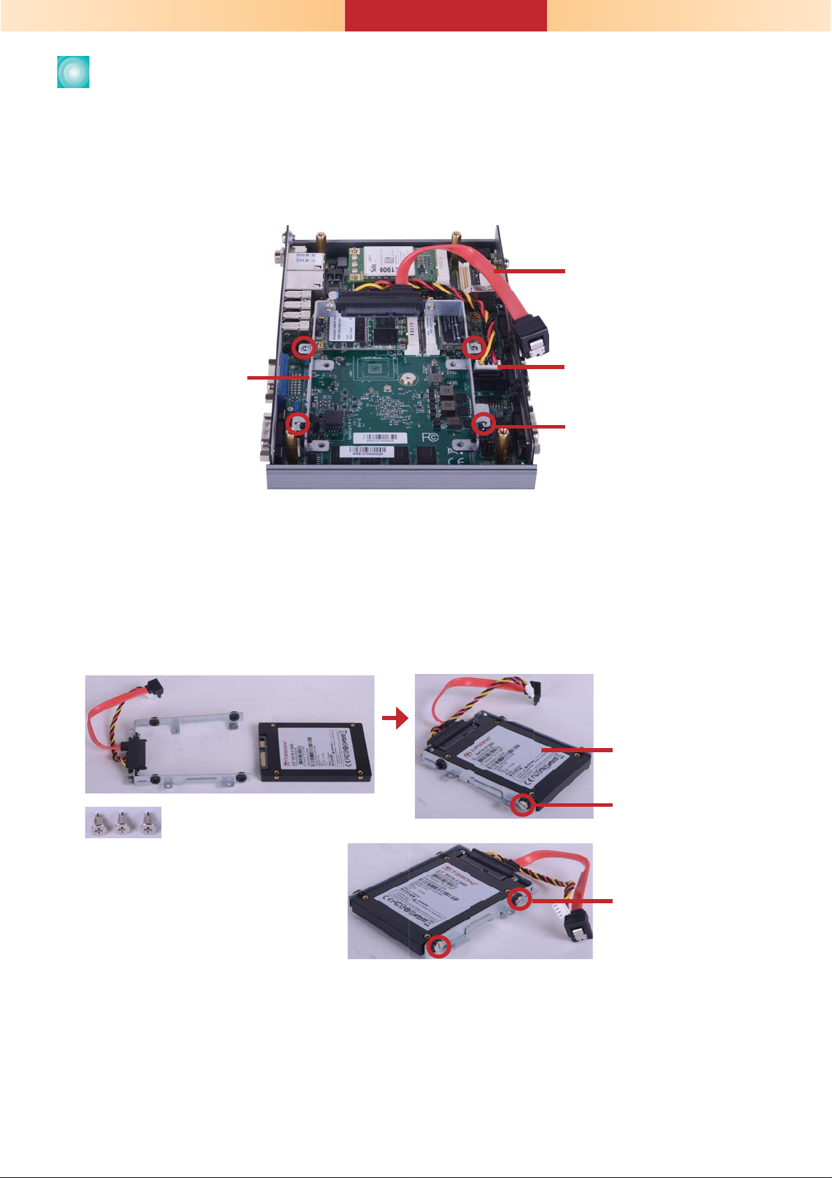
2. Align the mounting holes of the SATA drive with the mounting holes on the HDD bracket and then
use the 3 provided mounting screws to secure the drive in place.
SATA power cable
Mounting Screw
2.5" SA TA drive
Mounting Screw
Mounting Screw
Mounting Screw
2
Page 3

3. Place the SATA drive bay into the chassis. Secure the SATA drive bay with the mounting screws you
removed in step 1. And connect the SATA data cable and SATA power cable to the connectors on the
system board.
SATA power cable
SATA power connector
Mounting Screw
SATA data cable
SATA connector
Mounting Screw
3
Page 4

Board Layout and Jumper Settings
COM 3
JP22
1
31
1
1
1210
13
(JP21)
1210
COM 4
COM 2
SATA 2.0
COM 1
USB 0
USB 3.0
2
HDMI
Reset
Power
DDR3L
(JP20)
(JP18)
(JP17)
SATA 1
1
14
SATA
Power
Mini PCIe mSATA
iTE
IT8528E
1
(JP23)
LVDS LCD
Panel
3940
DDR3L
COM 4/DIO Select
Digital I/O 4-7 Output State
Digital I/O 0-3 Output State
Digital I/O Power Select
System Fan
USB 0
Power
1
Select
(JP5)
1
1
(JP25)
125
1
(JP2)
1
6
(JP3)
1
(JP4)
3
Auto Power-on Select
Backlight Enable Power Select
Dimming Mode Select
Panel Power Select
Mini PCIe
(JP22, JP21)
(JP18)
(JP20)
(JP17)
COM 6
210
9
1
1109
COM 5
(optional)
USB 5-7 Power
TOP BOTTOM
DDR3L
eMMC
MicroSD
(optional)
Select (JP7)
210
1
USB 2.0
(JP25)
(JP2)LCD/Inverter Power Select
(JP3)
(JP4)
(JP23)
1 1
9
DDR3L
USB 5
Battery
Buzzer
SPI
Flash
BIOS
USB 1-2
Power Select (JP6)
1
Chassis
Intrusion
Clear CMOS
Data (JP24)
VGA/DVI-I
Mic-in
4
USB 2.0
USB 1
USB 2
USB 6
USB 7
LAN 1
LAN 2
1
1
DC-in
Standby
Power LED
1
DDR3L
ASMedia
ASM1442
Intel
WGI210AT
DDR3L
Intel Atom
E3800 Series
Nuvoton
NCT6106D
Intel
USB4604
WGI210AT
SIM Card
DDR3L
SMSC
DDR3L
DDR3L
NXP
PTN3460
USB Power Select: 0 (JP5), 1-2 (JP6), 5-7 (JP7)
+5V_standby (default) 1-2 On
+5V 2-3 On
Clear CMOS Data JP24
Normal (default) 1-2 On
Clear CMOS Data 2-3 On
Panel Power Select JP23
+12V 1-2 On
+5V 3-4 On
+3.3V (default) 5-6 On
Backlight Enable Power Select JP3
+5V 1-2 On
+3.3V (default)
Dimming Mode Select JP4
Voltage Mode 1-2 On
PWM Mode (default) 2-3 On
LCD/Inverter Power Select JP2
+12V (default) 1-2 On
+5V 2-3 On
2-3 On
Auto Power-on Select JP25
Power-on via power button (default) 1-2 On
Power-on via AC power 2-3 On
Digital I/O Output State
JP18 (DIO 4-7)
JP20 (DIO 0-3)
GND (default) 1-2 On
+5V or +5V_standby 2-3 On
Digital I/O Power Select JP17
+5V_standby 1-2 On
+5V (default) 2-3 On
COM 4/DIO Select JP21, JP22
COM 4 (default)
DIO
1-2, 4-5
7-8, 10-11 On
2-3, 5-6
8-9, 11-12 On
Note:
You cannot use COM 4 and DIO at the same time. Please set up JP21
and JP22 together.
www.dfi .com
4
934-EC7000-0C0G
A33122526
 Loading...