

Page 1
www.dfi .com
1
Chapter 1 Introduction
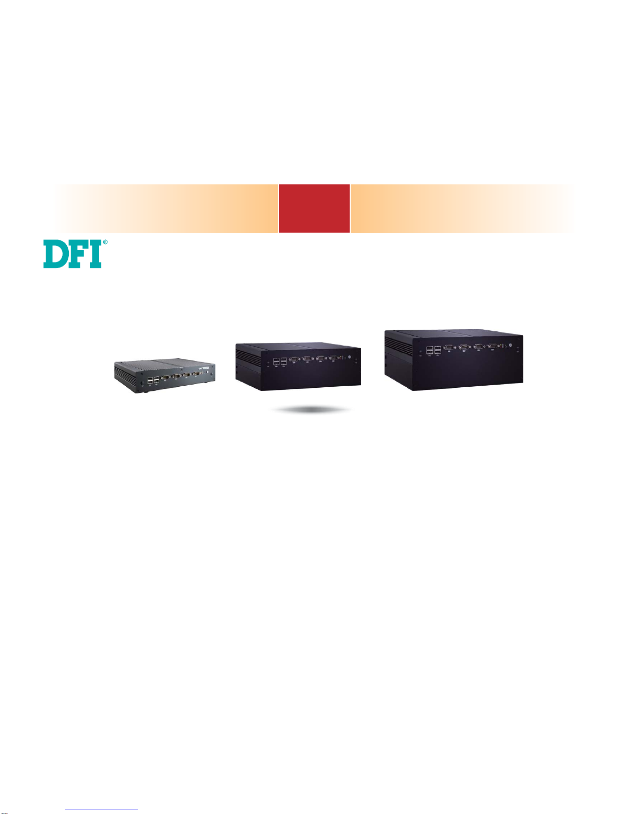
EC200/210/220/221-BT
Modular-Designed Embedded System
User’s Manual
A37510542
Page 2

www.dfi .com
2
Chapter 1 Introduction
Copyright
This publication contains information that is protected by copyright. No part of it may be reproduced in any form or by any means or used to make any transformation/adaptation without
the prior written permission from the copyright holders.
This publication is provided for informational purposes only. The manufacturer makes no
representations or warranties with respect to the contents or use of this manual and specifically disclaims any express or implied warranties of merchantability or fitness for any particular
purpose. The user will assume the entire risk of the use or the results of the use of this document. Further, the manufacturer reserves the right to revise this publication and make changes
to its contents at any time, without obligation to notify any person or entity of such revisions
or changes.
Changes after the publication’s first release will be based on the product’s revision. The website
will always provide the most updated information.
© 2015. All Rights Reserved.
Trademarks
Product names or trademarks appearing in this manual are for identification purpose only and
are the properties of the respective owners.
FCC and DOC Statement on Class A
This equipment has been tested and found to comply with the limits for a Class A digital
device, pursuant to Part 15 of the FCC rules. These limits are designed to provide reasonable protection against harmful interference when the equipment is operated in a residential
installation. This equipment generates, uses and can radiate radio frequency energy and, if not
installed and used in accordance with the instruction manual, may cause harmful interference
to radio communications. However, there is no guarantee that interference will not occur in a
particular installation. If this equipment does cause harmful interference to radio or television
reception, which can be determined by turning the equipment off and on, the user is encouraged to try to correct the interference by one or more of the following measures:
• Reorient or relocate the receiving antenna.
• Increase the separation between the equipment and the receiver.
• Connect the equipment into an outlet on a circuit different from that to which the receiver
is connected.
• Consult the dealer or an experienced radio TV technician for help.
Notice:
1. The changes or modifications not expressly approved by the party responsible for compli-
ance could void the user’s authority to operate the equipment.
2. Shielded interface cables must be used in order to comply with the emission limits.
Page 3

www.dfi .com
3
Chapter 1 Introduction
Table of Contents
Copyright ........................................................................................................... 2
Trademarks .......................................................................................................2
FCC and DOC Statement on Class A ...................................................2
About this Manual ......................................................................................... 4
Warranty ............................................................................................................4
Static Electricity Precautions ....................................................................4
Safety Measures ............................................................................................4
Safety Precautions ........................................................................................5
About the Package .......................................................................................5
Chapter 1 - Introduction ...........................................................................6
Overview ....................................................................................................... 6
Key Features ................................................................................................7
Specifications ............................................................................................... 8
Getting the Know the EC200/210/220/221-BT ..................................9
Mechanical Dimensions ........................................................................... 13
Chapter 2 - Getting Started ................................................................... 16
Preparing the System .............................................................................. 16
Installing Devices ..................................................................................... 16
Configuring the BIOS .............................................................................. 16
Installing the Operating System ..........................................................16
Installing the Drivers ............................................................................... 16
Chapter 3 - Installing the Devices ...................................................... 17
Removing the Chassis Cover .................................................................17
Installing a SODIMM Module ................................................................ 18
Installing a 2.5” SATA Drive .................................................................. 19
Installing a Mini PCIe and/or mSATA Card ....................................... 21
Installing the PCI/PCIe Expansion Card ............................................ 22
Chapter 4 - Jumper Settings ................................................................. 24
Jumper Settings - System Board ........................................................... 24
Clear CMOS Data ....................................................................................... 24
Auto Power-on Select ................................................................................ 24
USB Power Select ...................................................................................... 25
SATA DOM Power Select ............................................................................25
COM 1/COM 2/COM 3/COM 4 RS232/422/485 Select ................................... 26
COM 1/COM 2/COM 3/COM 4 RS232/Power Select ...................................... 27
Mini PCIe/mSATA Signal Select ................................................................... 27
Mini PCIe/mSATA Power Select ................................................................... 28
SATA 1/mSATA Signal Select ...................................................................... 28
Digital I/O Power Select ............................................................................. 29
Digital I/O Output State ............................................................................. 29
PS/2 Keyboard/Mouse Power Select ............................................................ 30
Jumper Settings - System Board ........................................................... 30
For EC200/EC210/EC220/EC221-BTA881
COM 7 to COM 10 RS232/422/485 Select ...................................................30
COM 7 to COM 10 RS232/Power Select ...................................................... 31
Digital I/O Power Select ............................................................................. 31
USB Power Select ...................................................................................... 32
For EC200/EC210/EC220/EC221-BTAG60
COM 7 to COM 10 RS232/422/485 Select ...................................................32
COM 7 to COM 10 RS232/Power Select ...................................................... 33
Digital I/O Power Select ............................................................................. 33
Chapter 5 - Ports and Connectors ...................................................... 34
Front Panel I/O Ports ..............................................................................34
USB Ports .................................................................................................34
COM (Serial) Ports ..................................................................................... 35
Rear Panel I/O Ports ...............................................................................36
9~36V DC-in ............................................................................................. 39
Speaker-out .............................................................................................. 40
VGA Port ................................................................................................... 40
DVI Port ................................................................................................... 41
RJ45 LAN Ports ......................................................................................... 41
USB Ports .................................................................................................42
8-bit GPIO ................................................................................................43
COM (Serial) Ports ..................................................................................... 43
I/O Connectors .......................................................................................... 44
Serial ATA Connectors ................................................................................. 44
Serial ATA Power Connectors ....................................................................... 44
Front Panel Connector ...............................................................................44
PS/2 Keyboard/Mouse Connector ................................................................. 45
USB Connectors ........................................................................................46
Parallel Connector ....................................................................................... 47
Digital I/O and/or Power Connector ............................................................ 47
Chassis Intrusion Connector ........................................................................48
Front Audio Connector ............................................................................... 48
S/PDIF Connector .......................................................................................49
Cooling Fan Connector ............................................................................... 49
LPC Connector ............................................................................................ 50
SMBus Connector ...................................................................................... 50
Expansion Slots .........................................................................................51
Standby Power LED ....................................................................................52
Battery .....................................................................................................52
Chapter 6 - Mounting Option ................................................................ 53
Wall Mount .................................................................................................53
Chapter 7 - BIOS Setup ...........................................................................54
Chapter 8 - Supported Software ......................................................... 67
Chapter 9 - Digital I/O Programming Guide .................................. 79
Appendix A - Watchdog Sample Code ..............................................81
Appendix B - System Error Message ................................................. 82
Appendix C - Troubleshooting Checklist ........................................... 83
Page 4

www.dfi .com
4
Chapter 1 Introduction
About this Manual
An electronic file of this manual is included in the CD. To view the user’s manual in the CD, insert the CD into a CD-ROM drive. The autorun screen (Main Board Utility CD) will appear. Click
“User’s Manual” on the main menu.
Warranty
1. Warranty does not cover damages or failures that arised from misuse of the product,
inability to use the product, unauthorized replacement or alteration of components and
product specifications.
2. The warranty is void if the product has been subjected to physical abuse, improper installation, modification, accidents or unauthorized repair of the product.
3. Unless otherwise instructed in this user’s manual, the user may not, under any circumstances, attempt to perform service, adjustments or repairs on the product, whether in or
out of warranty. It must be returned to the purchase point, factory or authorized service
agency for all such work.
4. We will not be liable for any indirect, special, incidental or consequencial damages to the
product that has been modified or altered.
Static Electricity Precautions
It is quite easy to inadvertently damage your PC, system board, components or devices even
before installing them in your system unit. Static electrical discharge can damage computer
components without causing any signs of physical damage. You must take extra care in handling them to ensure against electrostatic build-up.
1. To prevent electrostatic build-up, leave the system board in its anti-static bag until you are
ready to install it.
2. Wear an antistatic wrist strap.
3. Do all preparation work on a static-free surface.
4. Hold the device only by its edges. Be careful not to touch any of the components, contacts
or connections.
5. Avoid touching the pins or contacts on all modules and connectors. Hold modules or con
nectors by their ends.
Safety Measures
To avoid damage to the system:
• Use the correct AC input voltage range.
To reduce the risk of electric shock:
• Unplug the power cord before removing the system chassis cover for installation or servic-
ing. After installation or servicing, cover the system chassis before plugging the power cord.
Battery:
• Danger of explosion if battery incorrectly replaced.
• Replace only with the same or equivalent type recommend by the manufacturer.
• Dispose of used batteries according to local ordinance.
Important:
Electrostatic discharge (ESD) can damage your processor, disk drive and other components. Perform the upgrade instruction procedures described at an ESD workstation only. If such a station is not available, you can provide some ESD protection by
wearing an antistatic wrist strap and attaching it to a metal part of the system chassis. If a wrist strap is unavailable, establish and maintain contact with the system
chassis throughout any procedures requiring ESD protection.
Page 5

www.dfi .com
5
Chapter 1 Introduction
About the Package
The package contains the following items. If any of these items are missing or damaged,
please contact your dealer or sales representative for assistance.
• 1 system unit
• 1 HDD drive bay kit
-
2 Brackets
-
1 SATA data/power cable
-
4 Bracket screws
-
4 HDD screws
•
Terminal blocks
• 1 CD disk includes
- Drivers/Manual
• 1 Quick Installation Guide
Optional Items
• Wall Mount kit
• VESA Mount kit
• Power Cord
• Power Adapter
The board and accessories in the package may not come similar to the information listed
above. This may differ in accordance to the sales region or models in which it was sold. For
more information about the standard package in your region, please contact your dealer or
sales representative.
Before Using the System
Before powering-on the system, prepare the basic system components.
If you are installing the system board in a new system, you will need at least the following
internal components.
• Storage devices such as CFast card, Mini PCIe and/or mSATA card, etc.
You will also need external system peripherals you intend to use which will normally include at
least a keyboard, a mouse and a video display monitor.
Safety Precautions
• Use the correct DC input voltage range.
• Unplug the power cord before removing the system chassis cover for installation or servicing. After installation or servicing, cover the system chassis before plugging the power cord.
• Danger of explosion if battery incorrectly replaced.
• Replace only with the same or equivalent type recommend by the manufacturer.
• Dispose of used batteries according to local ordinance.
• Keep this system away from humidity.
• Place the system on a stable surface. Dropping it or letting it fall may cause damage.
• The openings on the system are for air ventilation to protect the system from overheating.
DO NOT COVER THE OPENINGS.
• Place the power cord in such a way that it will not be stepped on. Do not place anything on
top of the power cord. Use a power cord that has been approved for use with the system
and that it matches the voltage and current marked on the system’s electrical range label.
• If the system will not be used for a long time, disconnect it from the power source to avoid
damage by transient overvoltage.
• If one of the following occurs, consult a service personnel:
- The power cord or plug is damaged.
- Liquid has penetrated the system.
- The system has been exposed to moisture.
- The system is not working properly.
- The system dropped or is damaged.
- The system has obvious signs of breakage.
• The unit uses a three-wire ground cable which is equipped with a third pin to ground the
unit and prevent electric shock. Do not defeat the purpose of this pin. If your outlet does
not support this kind of plug, contact your electrician to replace the outlet.
• Disconnect the system from the DC outlet before cleaning. Use a damp cloth. Do not use
liquid or spray detergents for cleaning.
Page 6
www.dfi .com
6
Chapter 1 Introduction
Chapter 1 - Introduction
Chapter 1
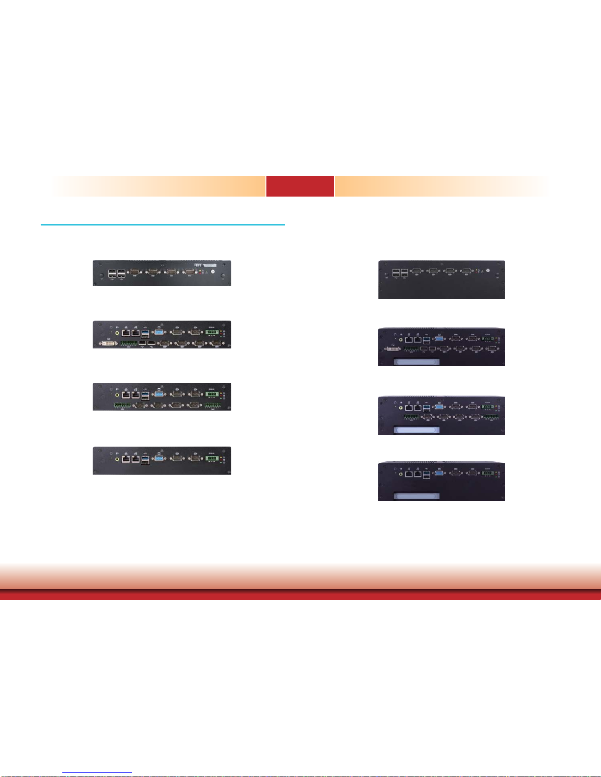
Overview (EC200-BT)
EC200-BTA881 Rear View
Front View
Overview (EC210-BT)
EC200-BTAG60 Rear View
EC200-BT6060 Rear View
EC210-BTA881 Rear View
Front View
EC210-BTAG60 Rear View
EC210-BT6060 Rear View
Page 7
www.dfi .com
7
Chapter 1 Introduction
Key Features
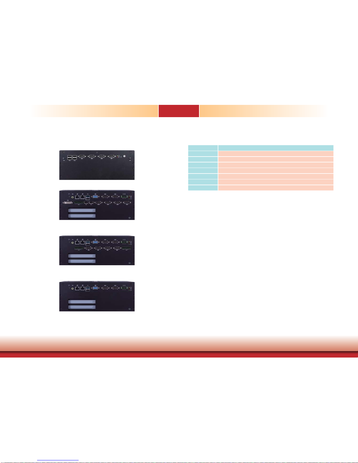
Model Name EC200/EC210/EC220/EC221-BT
Processor
Intel® AtomTM processor
Memory
Two 204-pin DDR3L SODIMM sockets support up to 8GB system memory
LAN
2 LAN ports
COM
up to 10 COM ports
Display
1 VGA, 1 DVI (DVI-D signal)
USB
1 Type A USB 3.0 port and USB 2.0 ports
GPIO
9-pole terminal block
Overview (EC220/EC221-BT)
Chapter 1
EC220/EC221-BTA881 Rear View
Front View
EC220/EC221-BTAG60 Rear View
EC220/EC221-BT6060 Rear View
Page 8

www.dfi .com
8
Chapter 1 Introduction
Environment
• Temperature
- Operating: 0
o
C~55oC (SSD/mSATA)
- Operating: 0
o
C~50oC (HDD)
- Operating: -10
o
C~70oC (wide-temp SSD, for EC200-BT6060 only)
- Storage: -20
o
C~85oC
• Operating Vibration
- IEC68-2-64 (HDD)
• Operating Shock
- Half sine wave 15G, 11ms, 3 shock per axis
Construction
• Aluminum + SGCC
Mounting
• Wall/VESA mount
- Mounting brackets and screws* (optional)
Dimensions
• EC200-BT: 275mm x 59mm x 203mm (W x H x D)
• EC210-BT: 275mm x 94mm x 203mm (W x H x D)
• EC220/EC221-BT: 275mm x 114mm x 203mm (W x H x D)
Weight
• EC200-BT: 3 kg
• EC210-BT: 3.5 kg
• EC220/EC221-BT: 4 kg
OS Support
• Windows 7, WES 7, Windows 8.1, WES 8
• Linux (Distribution available upon request)
WatchDog Timer
• Watchdog timeout programmable via software from 1 to 255 seconds
Certifi cation
• CE
• FCC Class A
• RoHS
Specifications
Processor System
• Intel® AtomTM E3845, Quad Core, 2M Cache, 1.91GHz, 10W
• 22nm process technology
Memory
• Two 204-pin DDR3L SODIMM sockets
- up to 8GB system memory
- dual channel memory interface
• Supports DDR3L 1333MHz
Graphics
• Intel® HD Graphics
• Display ports: 1 VGA, 1 DVI (DVI-D signal)
• Supports 2 independent displays
• VGA: resolution up to 2560x1600 @ 60Hz
• DVI: resolution up to 1920x1080 @ 60Hz
Storage
• 2 2.5" SATA drive bays
- SATA 2.0 port with data transfer rate up to 3Gb/s
- Standard: 1 SATA drive bay
- Option: 2 SATA drive bays (Available upon request. Please contact your
sales representative for more information.)
• Supports 1 mSATA module via the mini PCIe socket
Ethernet
• 2 Intel® WGI210AT PCI Express Gigabit Ethernet controllers
• Integrated 10/100/1000 transceiver
• Fully compliant with IEEE 802.3, IEEE 802.3u, IEEE 802.3ab
Expansion
• EC200-BT
- 1 Mini PCIe slot
: Supports USB and PCIe signals
: Supports mSATA, Wi-Fi or 3G* (optional)
: Supports half size or full size Mini PCIe card
• EC210-BT
- 1 PCI slot
- 1 Mini PCIe slot
: Supports USB and PCIe signals
: Supports mSATA, Wi-Fi or 3G* (optional)
: Supports half size or full size Mini PCIe card
• EC220-BT
- 2 PCI slots
- 1 Mini PCIe slot
: Supports USB and PCIe signal
: Supports mSATA, Wi-Fi or 3G* (optional)
: Supports half size or full size Mini PCIe card
• EC221-BT
- 1 PCIe x16 slot (x1 signal)
- 1 PCI slot
- 1 Mini PCIe slot
: Supports USB and PCIe signal
: Supports mSATA, Wi-Fi or 3G* (optional)
: Supports half size or full size Mini PCIe card
Audio
• Realtek® ALC888 High Defi nition Audio
• 2 watt, 4Ω power amplifi er
Power
• Power input voltage: 9~36V DC-in
Chapter 1
Note:
*Optional and is not supported in standard model. Please contact your sales representative for more information.
Page 9
www.dfi .com
9
Chapter 1 Introduction
Getting to Know the EC200/EC210/EC220/EC221-BT
Chapter 1
EC200-BT
Front View
Rear View
Alert LED
HDD LED
Reset
Power
USB
Wi-Fi Module
Antenna Hole
Wi-Fi Module
Antenna Hole
EC200-BTA881 Rear View
COM7
COM8
COM9
COM10USB
GPIO
Power
HDD
Alert
DVI
(DVI-D signal)
DC-in
COM5
COM6
VGAUSB
LAN
Speaker-out
Reset
EC200-BTAG60 Rear View
GPIO COM7COM8COM9 GPIOCOM10
Power
DC-inCOM5COM6VGAUSBLAN
Speaker-out
Reset
Power
HDD
Alert
DC-inCOM5COM6VGAUSBLAN
Speaker-out
Reset
EC200-BT6060 Rear View
HDD
Alert
COM 1~4
Wi-Fi Module Antenna Hole
Used to connect to a Wi-Fi antenna.
USB Ports
Used to connect USB 2.0/1.1 devices.
COM Ports
Used to connect serial devices.
HDD LED
Indicates the status of the hard drive.
Alert LED
Indicates the status when the CPU is over temperature.
Reset Button
Press to reset the system.
Power Button
Press to power-on or power-off the system.
Page 10

www.dfi .com
10
Chapter 1 Introduction
EC210-BT
Front View
Chapter 1
Alert LED
HDD LED
Reset
Power
USB
Wi-Fi Module
Antenna Hole
Wi-Fi Module
Antenna Hole
COM 1~4
Power LED
Indicates the power status of the system.
HDD LED
Indicates the status of the hard drive.
Alert LED
Indicates the status when the CPU is over temperature.
DC-in
Used to plug a power adapter.
COM Ports
Used to connect serial devices.
DVI Port
Used to connect a DVI device.
VGA Port
Used to connect an analog VGA monitor.
USB Ports
Used to connect USB 2.0 or 3.0 devices.
LAN Ports
Used to connect systems to a local area network.
GPIO
Supports 8-bit digital output and input.
Speaker-out
Used to connect to a speaker.
Reset Button
Indicates the reset status of the system.
Wi-Fi Module Antenna Hole
Used to connect to a Wi-Fi antenna.
USB Ports
Used to connect USB 2.0/1.1 devices.
COM Ports
Used to connect serial devices.
HDD LED
Indicates the status of the hard drive.
Alert LED
Indicates the status when the CPU is over temperature.
Reset Button
Press to reset the system.
Power Button
Press to power-on or power-off the system.
Page 11

www.dfi .com
11
Chapter 1 Introduction
Rear View
Chapter 1
EC210-BTA881 Rear View
COM7COM8COM9COM10USBGPIO
Power
HDD
Alert
DVI
(DVI-D signal)
DC-in
COM5COM6VGAUSB
LAN
Speaker-out
Reset
PCI Slot
EC210-BTAG60 Rear View
GPIO
COM7COM8COM9 GPIOCOM10
PCI Slot
Power
HDD
Alert
DC-in
COM5COM2VGAUSB
LAN
Speaker-out
Reset
Power
HDD
Alert
DC-in
COM1COM2VGAUSB
LAN
Speaker-out
Reset
EC210-BT6060 Rear View
PCI Slot
Power LED
Indicates the power status of the system.
HDD LED
Indicates the status of the hard drive.
Alert LED
Indicates the status when the CPU is over temperature.
DC-in
Used to plug a power adapter.
COM Ports
Used to connect serial devices.
DVI Port
Used to connect a DVI device.
VGA Port
Used to connect an analog VGA monitor.
USB Ports
Used to connect USB 2.0 or 3.0 devices.
LAN Ports
Used to connect systems to a local area network.
GPIO
Supports 8-bit digital output and input.
Speaker-out
Used to connect to a speaker.
Reset Button
Indicates the reset status of the system.
PCI slot
Supports to add on riser cards.
Page 12
www.dfi .com
12
Chapter 1 Introduction
EC220/EC221-BT
Front View
Rear View
Chapter 1
Alert LED
HDD LED
Reset
Power
USB
Wi-Fi Module
Antenna Hole
Wi-Fi Module
Antenna Hole
COM1~4
Wi-Fi Module Antenna Hole
Used to connect to a Wi-Fi antenna.
USB Ports
Used to connect USB 2.0/1.1 devices.
COM Ports
Used to connect serial devices.
HDD LED
Indicates the status of the hard drive.
Alert LED
Indicates the status when the CPU is over temperature.
Reset Button
Press to reset the system.
Power Button
Press to power-on or power-off the system.
EC220/EC221-BTA881 Rear View
PCI / PCIe x16
(x1 signal) slot
COM7COM8COM9COM10USB USB
GPIO
Power
HDD
Alert
DVI
(DVI-D signal)
DC-inCOM5COM6VGAUSBLAN
Speaker-out
Reset
EC220/EC221-BTAG60 Rear View
PCI / PCIe x16
(x1 signal) slot
Power
HDD
Alert
DC-inCOM5COM6VGAUSBLAN
Speaker-out
Reset
GPIOGPIO
COM7COM8COM9COM10
EC220/EC221-BT6060 Rear View
Power
DC-inCOM5COM6VGAUSBLAN
Speaker-out
Reset
HDD
Alert
PCI / PCIe x16
(x1 signal) slot
Page 13
www.dfi .com
13
Chapter 1 Introduction
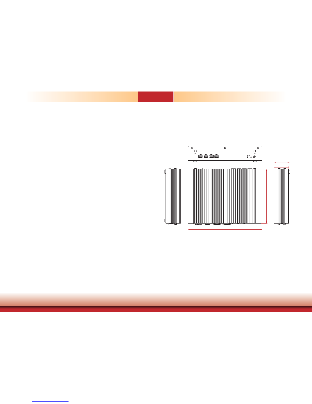
Mechanical Dimensions
Chassis Dimension (EC200-BT)
Front View
Right ViewLeft View
55.00
59.00
275.00
203.00
Chapter 1
Power LED
Indicates the power status of the system.
HDD LED
Indicates the status of the hard drive.
Alert LED
Indicates the status when the CPU is over temperature.
DC-in
Used to plug a power adapter.
COM Ports
Used to connect serial devices.
DVI Port
Used to connect a DVI device.
VGA Port
Used to connect an analog VGA monitor.
USB Ports
Used to connect USB 2.0 or 3.0 devices.
LAN Ports
Used to connect systems to a local area network.
GPIO
Supports 8-bit digital output and input.
Speaker-out
Used to connect to a speaker.
Reset Button
Indicates the reset status of the system.
PCI/PCIe slot
Supports to add on riser cards.
Page 14
www.dfi .com
14
Chapter 1 Introduction
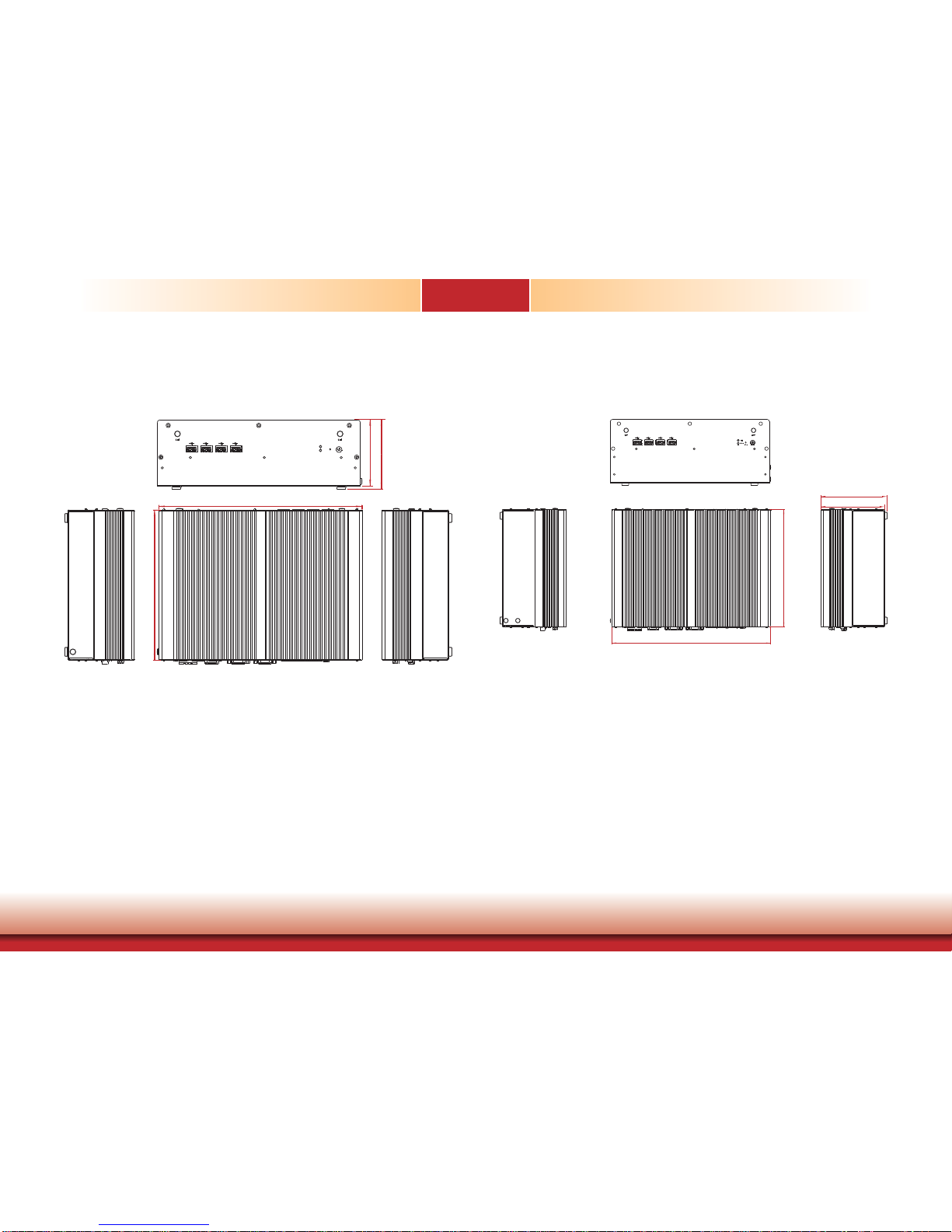
Chapter 1
Chassis Dimension (EC210-BT)
Front View
Right ViewLeft View
275.00
203.00
90.00
94.00
Chassis Dimension (EC220/EC221-BT)
Front View
Right ViewLeft View
110.00
114.00
275.00
203.00
Page 15
www.dfi .com
15
Chapter 1 Introduction
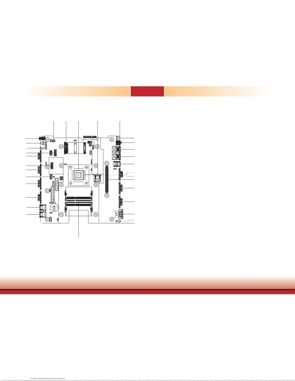
Motherboard Dimension
BT263
Chapter 1
5.00
0.00
23.60
55.50
91.50
127.27
154.50
173.50
192.50
210.00
222.00
121.15
196.00
209.00
221.00
0.00
173.00
140.14
114.00
58.00
22.50
40.50
67.00
103.00
139.00
175.00
107.43
125.10
107.43
183.44
149.86
Page 16

www.dfi .com
16
Chapter 2 Getting Started
Chapter 2 - Getting Started
Chapter 2
Preparing the System
Before you start using the system, you need the following items:
• SATA hard drive
• AC power adapter
• CD-ROM drive (for installing software/drivers)
• Screwdriver
• Memory module
Installing Devices
The following are devices that can be installed in the system.
• Memory module
• SATA hard drive
• Mini PCIe card
Configuring the BIOS
To get you started, you may need to change configurations such as the date, time and the
type of hard disk drive.
1. Power-on the system.
2. After the memory test, the message “Press DEL to run setup” will appear on the screen.
Press the Delete key to enter the AMI BIOS setup utility.
Installing the Operating System
Most operating system software are provided in a CD therefore you need to install a CD-ROM
drive in order to use the CD.
Make sure a 2.5” SATA drive is already installed.
1. Refer to the following chapters for information on connecting a CD-ROM drive and installing a SATA drive.
2. Refer to your operating system manual for instructions on installing the operating system.
Installing the Drivers
The system package includes a CD disk. The CD includes drivers that must be installed to provide the best system performance. Refer to the Supported Software chapter for instructions on
installing the drivers.
Page 17
www.dfi .com
17
Chapter 3 Installing the Devices
Chapter 3
Chapter 3 - Installing the Devices
Removing the Chassis Cover
1. Make sure that the system and all other peripheral devices connected to it have been
powered-off.
2. Disconnect all power cords and cables.
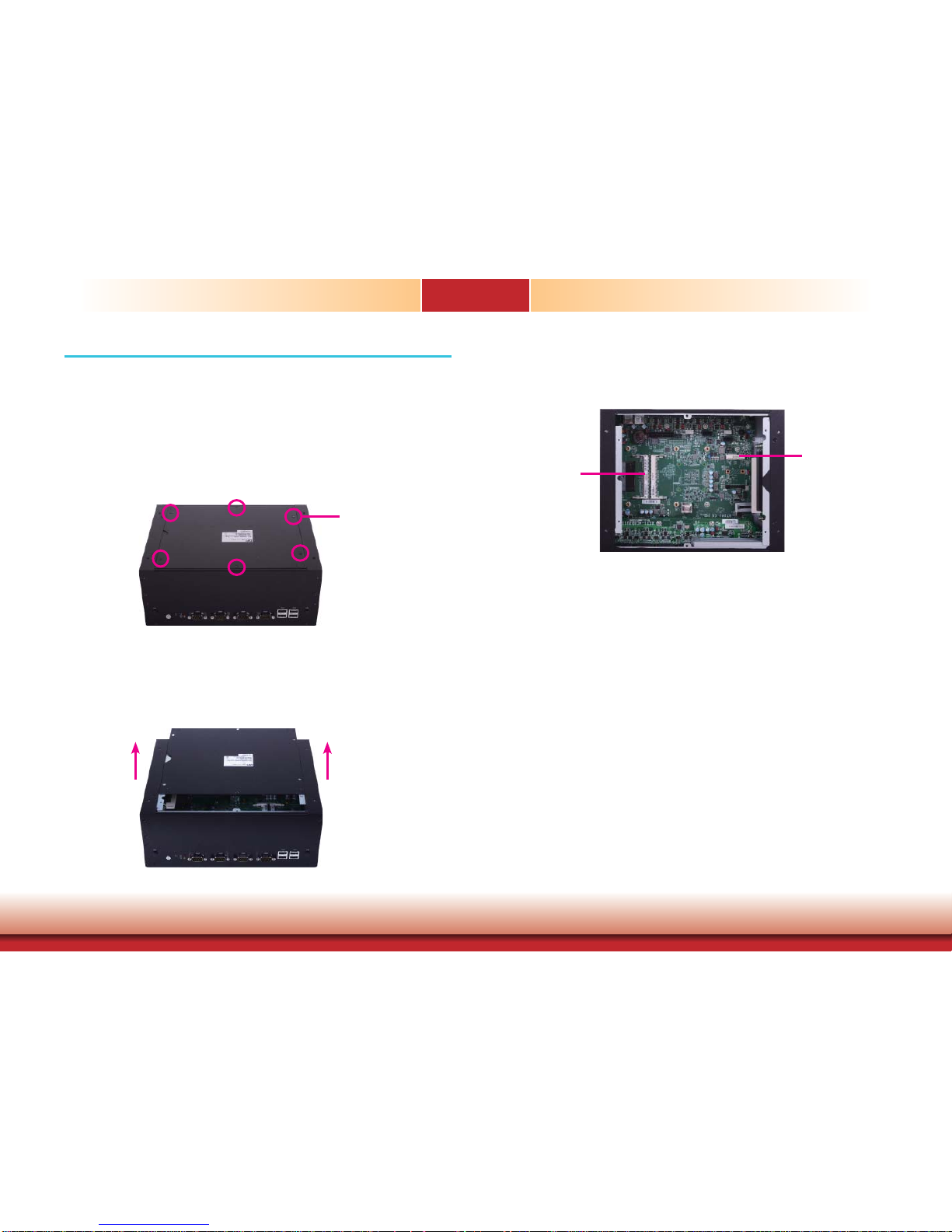
3. The 6 mounting screws on the bottom side of the system are used to secure the cover to
the chassis. Remove these screws and then put them in a safe place for later use.
Mounting Screw
4. After removing the mounting screws, lift the cover up.
Lift the Cover Upward
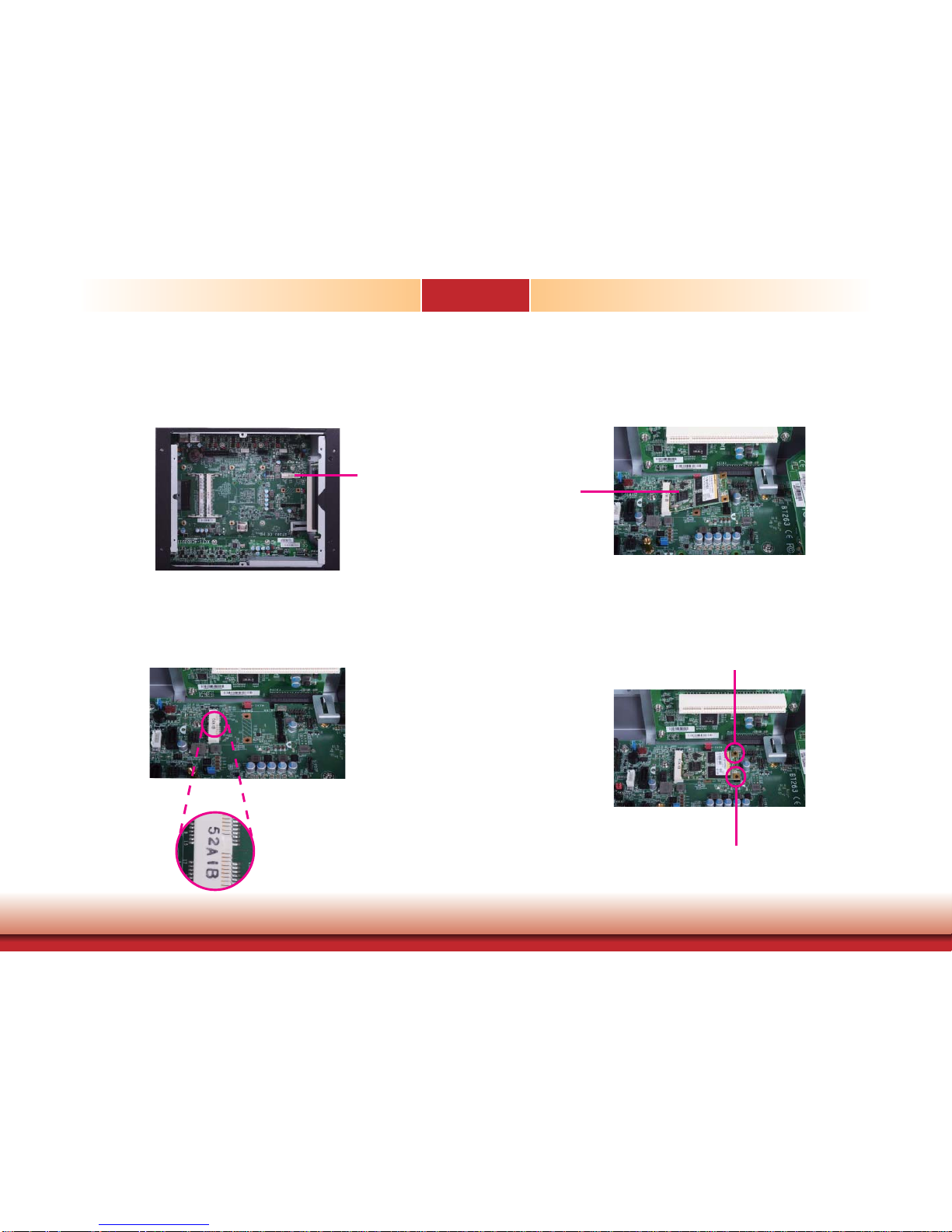
5. The SODIMM socket and the Mini PCie slot are readily accessible after removing the chassis
cover.
SODIMM socket
Mini PCIe slot
Page 18
www.dfi .com
18
Chapter 3 Installing the Devices
Chapter 3
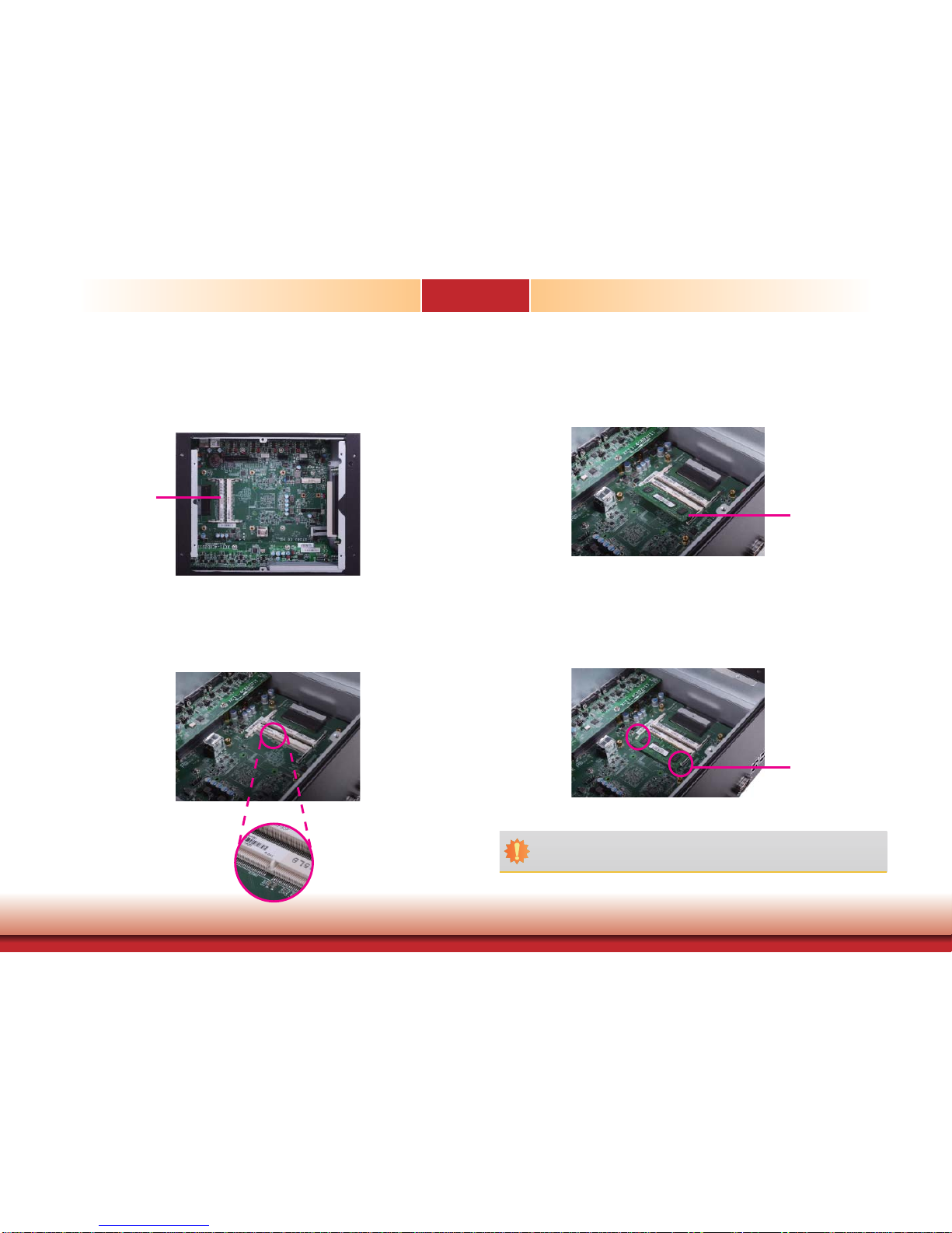
Installing a SODIMM Module
1. The SODIMM socket is located on the system board.
2. Note the key on the socket. The key ensures the module can be plugged into the socket in
one direction only.
3. Grasping the module by its edges, align the module into the socket at an approximately 30
degrees angle. Apply firm even pressure to each end of the module until it slips down into
the socket. The contact fingers on the edge of the module will almost completely disappear
inside the socket.
4. Push the module down until the clips at each end of the socket lock into position. You will
hear a distinctive “click”, indicating that the module is correctly locked into position.
Clip
SODIMM socket
SODIMM Module
Important:
When installing one DDR3L SODIMM only, make sure to install it into the SODIMM 1
socket.
Page 19
www.dfi .com
19
Chapter 3 Installing the Devices
Chapter 3
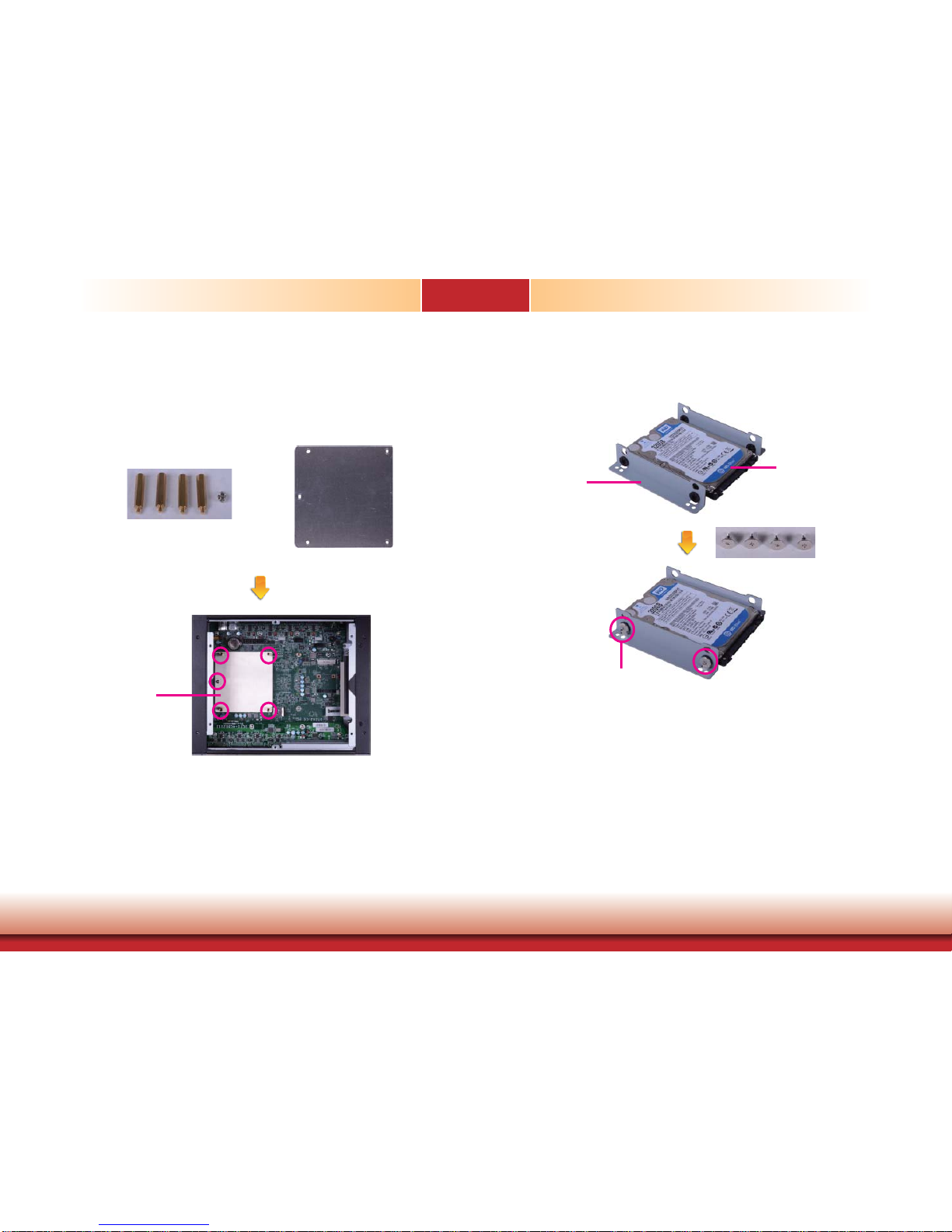
Installing a 2.5” SATA Drive
1. First, use the 5 provided mounting screws to secure the protective plate in place on the
system board.
Mounting Screws
Protective plate
Heat-dissipating
plate
2. Align the mounting holes of the SATA drive with the mounting holes on the HDD brackets
and then use the provided mounting screws to secure the drive in place.
HDD bracket
SATA drive
Mounting screw
Page 20
www.dfi .com
20
Chapter 3 Installing the Devices
Chapter 3
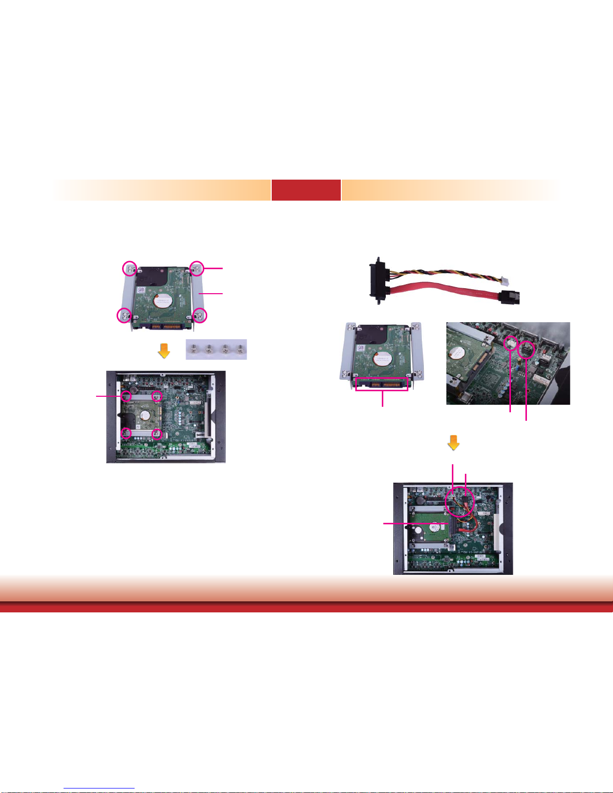
3. Place the SATA drive (with HDD brackets) into the system. Align the mounting holes on the
HDD brackets with the mounting holes on the heat-dissipating plate and then use the provided mounting screws to secure the drive in place.
Mounting screw
Mounting hole
4. Connect A to the SATA data/power connector on the SATA drive, B and C to the SATA
power connector and the SATA data connector respectively on the system board.
SATA data/power
connector
SATA power connector
SATA data connector
HDD bracket
SATA data/power
connector (A)
SATA power connector (B)
SATA data connector (C)
SATA data/power connector (A)
SATA power connector (B)
SATA data connector (C)
Page 21
www.dfi .com
21
Chapter 3 Installing the Devices
Chapter 3
Installing a Mini PCIe Card and/or mSATA Card
3. Grasping the Mini PCIe card by its edges, align the card into the slot at an approximately 30
degrees angle. Apply fi rm even pressure to each end of the card until it slips down into the
slot. The contact fi ngers on the edge of the card will almost completely disappear inside the
slot.
4. Push the Mini PCIe card down until the clips at each end of the latch lock into position. You
will hear a distinctive “click”, indicating that the card is correctly locked into position.
1.
The Mini PCIe slot is located on the system board
.
2. The system board is equipped with 1 Mini PCIe slot. The Mini PCIe slot supports a half length
or a full length Mini PCIe card. Note the key on the slot. The key ensures the Mini PCIe card
can be plugged into the slot in one direction only.
Mini PCIe slot
Mini PCIe card
Clip
Clip
Page 22
www.dfi .com
22
Chapter 3 Installing the Devices
Chapter 3
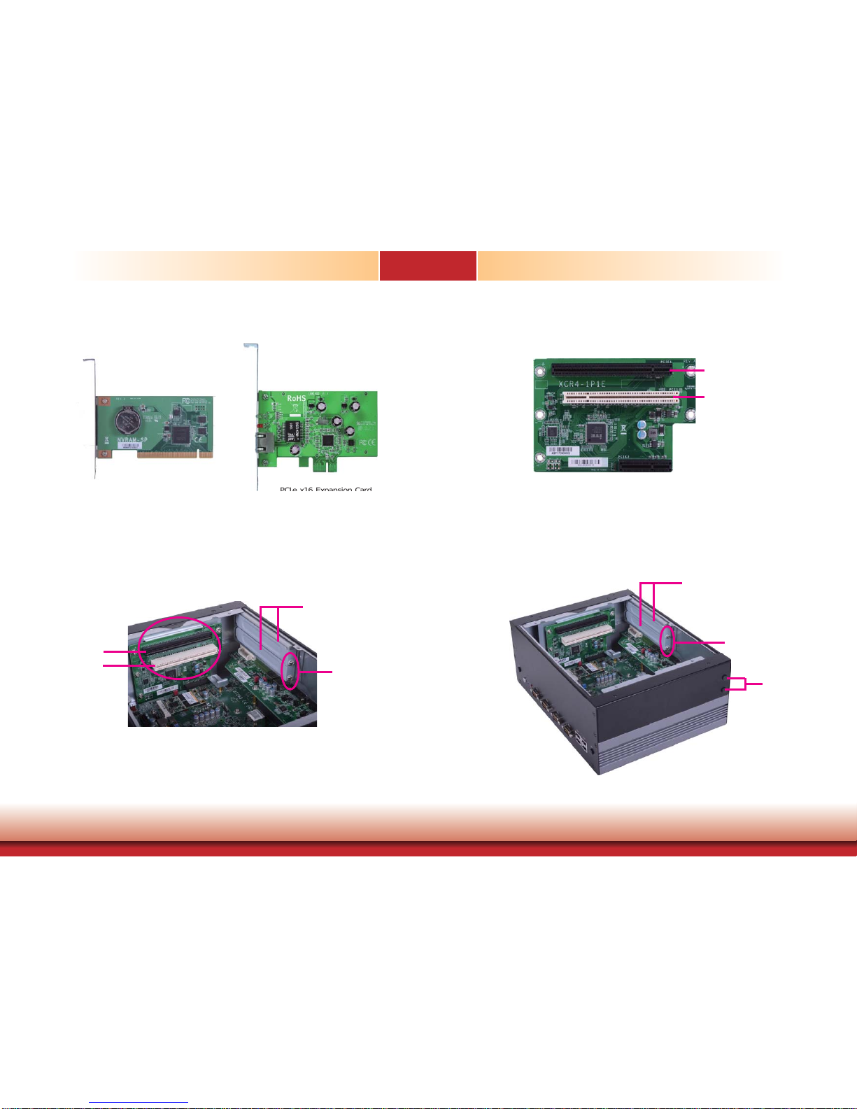
Installing the PCI/PCIe Expansion Card
PCI Expansion Card
PCIe x16 Expansion Card
(PCIe x1 signal)
PCI slot
PCIe x16 slot
PCI slot
PCIe x16 slot
Hole plug
Bracket
Mounting Screw
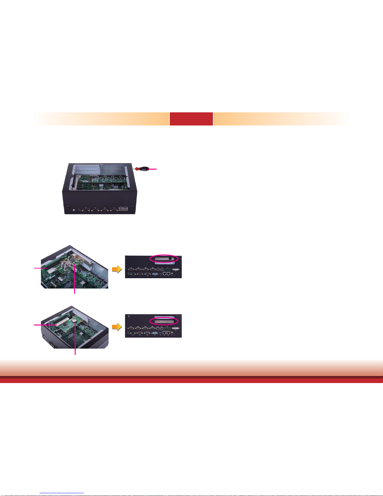
2. To remove the mounting screws and the brackets, you need to remove the hole plugs and
insert the screwdriver through the holes to access the mounting screws.
Bracket
Mounting Screw
1. The PCI slot and the PCIe x16 slot on the riser card are used to install the expansion
cards. To install the expansion cards, you need to remove the mounting screws that secure
the brackets to the chassis and then remove the brackets.
Page 23
www.dfi .com
23
Chapter 3 Installing the Devices
Chapter 3
4. Insert one expansion card with a bracket into the PCI slot and the PCIe x16 slot respectively
that are on the riser card and secure the bracket in place.
PCIe x16 slot
Expansion card
3. Remove these mounting screws and brackets, and then put them in a safe place for later
use.
Screwdriver
Rear View
Rear View
Expansion card
PCI slot
Page 24
www.dfi .com
24
Chapter 4 Jumper Settings
Chapter 4
Chapter 4 - Jumper Settings
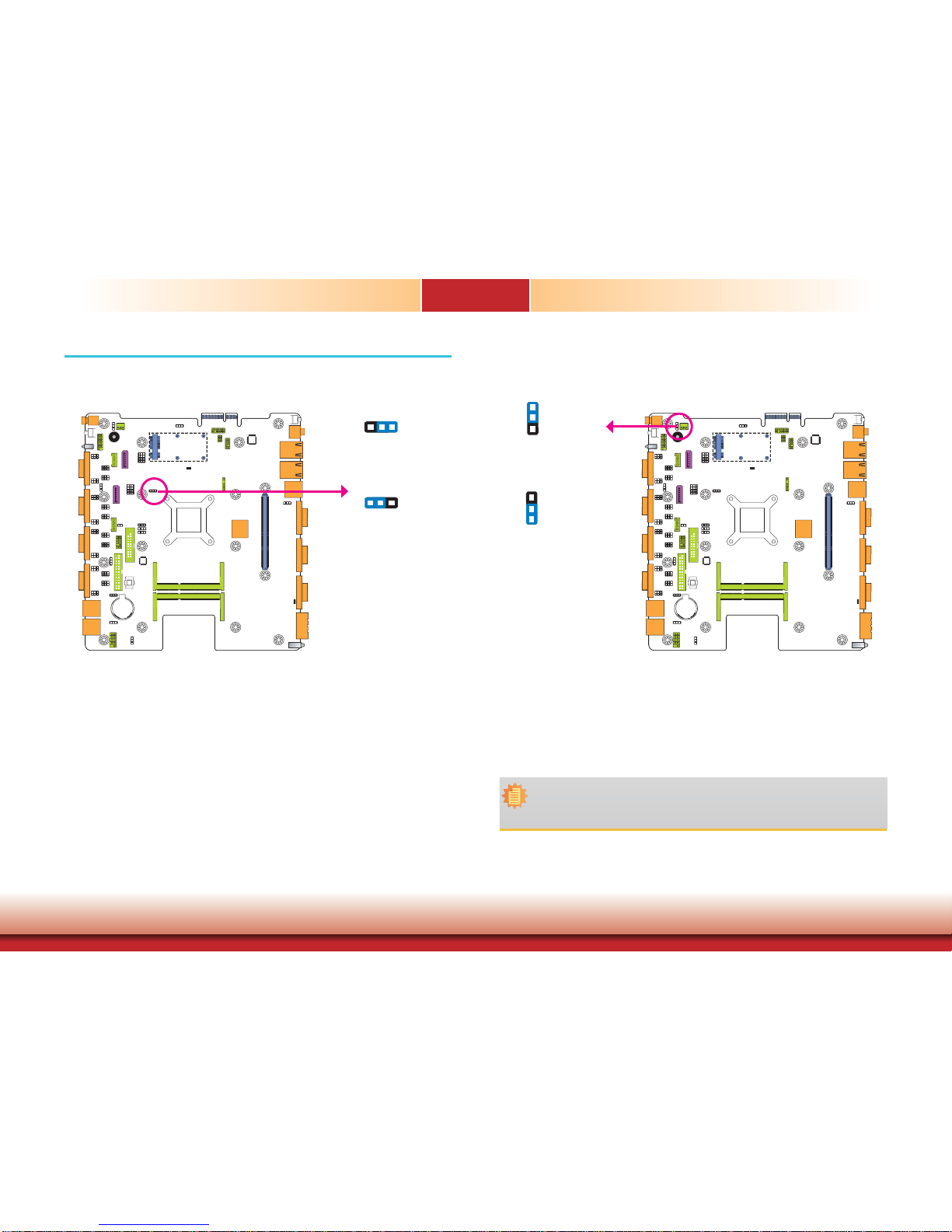
Auto Power-on Select
If you encounter that CMOS data becomes corrupted, you can reconfigure the system with the
default values stored in the ROM BIOS.
To load the default values stored in the ROM BIOS, please follow the steps below.
1. Power-off the system and unplug the power cord.
2. Set JP4 pins 2 and 3 to On. Wait for a few seconds and set JP4 back to its default setting,
pins 1 and 2 On.
3. Now plug the power cord and power-on the system.
2-3 On:
Clear CMOS Data
1-2 On:
Normal (default)
JP4
1-2 On:
Power-on via power button
(default)
2-3 On:
Power-on via AC power
JP12 is used to select the method of powering on the system. If you want the system to
power-on whenever AC power comes in, set JP12 pins 2 and 3 to On. If you want to use the
power button, set pins 1 and 2 to On.
When using the JP12 “Power On” feature to power the system back on after a power failure
occurs, the system may not power on if the power lost is resumed within 5 seconds (power
flicker).
Note:
In order to ensure that power is resumed after a power failure that re covers within a
5 second period, set JP12 to 2-3 On and the “Restore AC Power Loss” in CMOS is set
to “Power On”.
JP12
32
132
1
3
1
2
3
1
2
Jumper Settings - System Board
Clear CMOS Data
Page 25
www.dfi .com
25
Chapter 4 Jumper Settings
Chapter 4
JP1, JP9, JP10 and JP11 are used to select the power of the USB ports. Selecting +5V_standby
will allow you to use a USB device to wake up the system.
USB Power Select
2-3 On:
+5V_standby
(default)
1-2 On: +5V
Important:
If you are using the Wake-On-USB Keyboard/Mouse function for 2 USB ports, the
+5V_standby power source of your power supply must support ≥1.5A. For 3 or more
USB ports, the +5V_standby power source of your power supply must support ≥2A.
USB 0-1
(JP1)
USB 10-11
(JP9)
SATA DOM Power Select
1-2 On: +5V (default)
2-3 On: GND
JP22 is used to select the power level of SATA DOM.
JP22
SATA 0
USB 4-5
(JP10)
USB 6-7
(JP11)
132
3
1
2
3
1
2
1-2 On: +5V 2-3 On:
+5V_standby
(default)
Note:
SATA port 0 provides adequate space for SATA DOM.
1
3
2
1
3
2
32
1
Page 26
www.dfi .com
26
Chapter 4 Jumper Settings
Chapter 4
COM 1/COM 2/COM 3/COM 4 RS232/422/485 Select
All these jumpers on the system board are used to configure the COM 1 (JP15, JP23 and
JP24)/COM 2 (JP17, JP25 and JP26)/COM 3 (JP19, JP27 and JP28)/COM 4 (JP21, JP29 and
JP30) port to RS232, RS422 (Full Duplex) or RS485. The pin functions of the COM 1/COM 2/
COM 3/COM 4 port will vary according to these jumpers’ setting.
5-6 On: RS485
642
531
1-2 On: RS232
(default)
3-4 On: RS422
Full Duplex
642
531
642
531
1-3, 2-4 On:
RS232 (default)
3-5, 4-6 On:
RS422 Full Duplex/RS485
COM 1 to COM 4:
RS232/422/485
642
531
642
531
JP23
JP24
JP25
JP26
JP15
JP17
JP19
JP21
JP27
JP28
JP29
JP30
COM 1/ COM 2/ COM 3/ COM 4
JP15 (for COM 1)/ JP17 (for COM 2)/ JP19 (for COM 3)/ JP21 (for COM 4)
JP23 and JP24 (for COM 1)/ JP25 and JP26 (for COM 2)
JP27 and JP28 (for COM 3)/ JP29 and JP30 (for COM 4)
RS485
DATA+
DATA-
RS422
Full Duplex
RXD+
TXD+
RXD-
TXD-
N.C.
N.C.
RS232
DCD-
TD
RD
DTR-
GND
RTS-
RI-
DSR-
CTS-
6789
12345
6789
12345
6789
12345
N.C.
N.C.
N.C.
N.C.
N.C.
N.C.
N.C.
N.C.
N.C.
N.C.
Note:
1. When COM 1 RS232/422/485 is selected, JP23 and JP24 must be set in accordance
to JP15.
2. When COM 2 RS232/422/485 is selected, JP25 and JP26 must be set in accordance
to JP17.
3. When COM 3 RS232/422/485 is selected, JP27 and JP28 must be set in accordance
to JP19.
4. When COM 4 RS232/422/485 is selected, JP29 and JP30 must be set in accordance
to JP21.
5. To make the RS485 auto flow control function work on COM 1 to COM 4, please
set either 8 data bits + 1 stop bit or one of the following settings:
(1) 8 data bits + 1 parity bit + 1 stop bit
(2) 8 data bits + 1 parity bit + 2 stop bits
(3) 8 data bits + 2 stop bits
Page 27

www.dfi .com
27
Chapter 4 Jumper Settings
Chapter 4
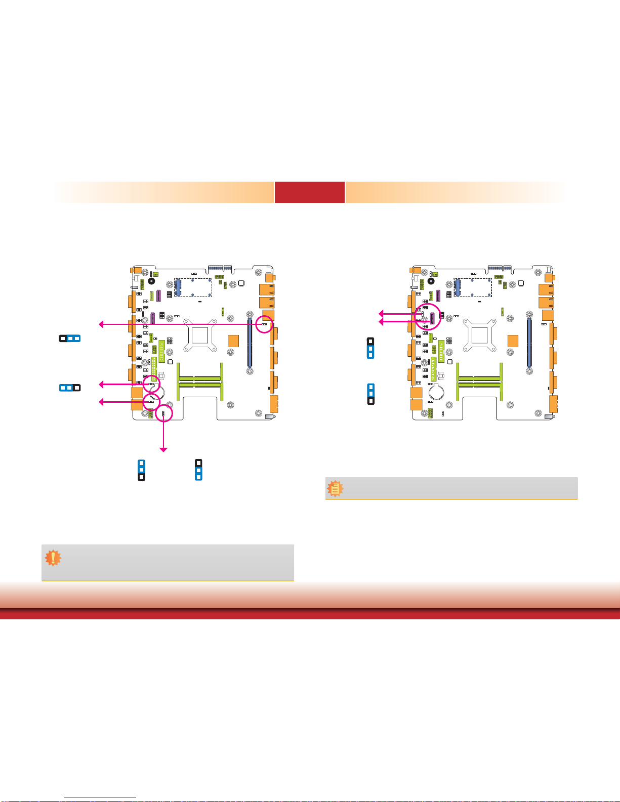
Mini PCIe/mSATA Signal Select
JP8 is used to select the Mini PCIe signal: PCIe or mSATA.
COM 1/COM 2/COM 3/COM 4 RS232/Power Select
1-3 (RI), 2-4 (DCD) On:
RS232 (default)
3-5 (+5V), 4-6 (+12V) On:
RS232 with power
JP14 (for COM 1), JP16 (for COM 2), JP18 (for COM 3) and JP20 (for COM 4) are used to configure these Serial COM ports to pure RS232 or RS232 with power.
2-5-8-11, 3-6-9-12 On:
mSATA
1-4-7-10, 2-5-8-11 On:
PCIe (default)
JP8
3 1
12
10
642
531
642
531
3 1
12
10
JP14
JP16
JP18
JP20
Page 28

www.dfi .com
28
Chapter 4 Jumper Settings
Chapter 4
Mini PCIe/mSATA Power Select
JP3 allows you to select the power rail for the Mini PCIe or mSATA device.
JP3
2-3 On: +3.3V (mSATA)
1-2 On: +3V_standby (Mini PCIe)
(default)
SATA 1/mSATA Signal Select
JP31
2-5-8-11, 3-6-9-12 On:
mSATA
1-4-7-10, 2-5-8-11 On:
SATA 1 (default)
JP31 is designed to select the SATA or mSATA signal.
132
32
1
1 3
10
12
1 3
10
12
Page 29

www.dfi .com
29
Chapter 4 Jumper Settings
Chapter 4
Digital I/O Power Select
2-3 On: +5V (default)
1-2 On: +5V_standby
JP7 is used to select the power of DIO (Digital I/O) signal.
JP7
Digital I/O Output State
Based on the power level of DIO (Digital I/O) selected on JP7, JP5 (DIO pin 11/13/15/17) and
JP6 (DIO pin 3/5/7/9) are used to select the state of DIO output: pull high or pull low. When
selecting pull high, the power selection will be the same as JP7’s setting.
2-3 On: GND
(default)
1-2 On: +5V or
+5V_standby
132
32
1
132
32
1
DIO 3/5/7/9
(JP6)
DIO 11/13/15/17
(JP5)
Page 30

www.dfi .com
30
Chapter 4 Jumper Settings
Chapter 4
JP13 is used to select the power of the PS/2 keyboard/mouse port. Selecting +5V_standby will
allow you to use the PS/2 keyboard or PS/2 mouse to wake up the system.
JP13
Important:
The +5V_standby power source of your power supply must support ≥720mA.
2-3 On:
+5V_standby
1-2 On: +5V
(default)
PS/2 Keyboard/Mouse Power Select
3
1
2
3
1
2
Jumper Settings - I/O Board
For EC200/EC210/EC220/EC221-BTA881
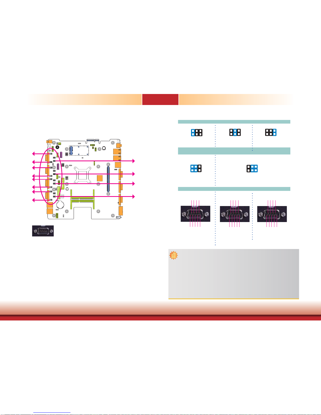
COM 7 to COM 10 RS232/RS422/RS485 Select
JP1 JP2 JP5 JP8
COM 7
(JP1)
COM 8
(JP2)
COM 9
(JP5)
COM 10
(JP8)
JP1 (for COM 7), JP2 (for COM 8), JP5 (for COM 9) and JP8 (for COM 10) are used to configure the COM ports to RS232, RS422 (Full Duplex) or RS485.
The pin function of the COM ports will vary according to these jumpers’ settings respectively.
5-6 On: RS485
6
4
2
5
3
1
1-2 On: RS232
(default)
3-4 On: RS422
Full Duplex
JP1 (for COM 7)/ JP2 (for COM 8)/ JP5 (for COM 9)/ JP8 (for COM 10)
COM 7/ COM 8/ COM 9/ COM 10
DCD
TXD
RXD
DTR
GND
1
2345
689
7
DSR
CTS
RTS
RI
6
4
2
5
3
1
6
4
2
5
3
1
RX+
TX+
RX-
TX-
GND
1
2345
689
7
N.C.
N.C.
N.C.
N.C.
DATA+
N.C.
DATA-
N.C.
GND
1
2345
689
7
N.C.
N.C.
N.C.
N.C.
Page 31

www.dfi .com
31
Chapter 4 Jumper Settings
Chapter 4
COM 7 to COM 10 RS232/Power Select Digital I/O Power Select
JP3, JP4, JP6 and JP7 are used to configure COM 7 to COM 10 to pure RS232 or RS232 with
power.
The pin function of COM 7 to COM 10 will vary according to JP3’s, JP4’s, JP6’s and JP7’s setting respectively.
1-3, 2-4 On:
RS232 (default)
3-5(+12V), 4-6(+5V) On:
RS232 with power
DCD
TXD
RXD
DTR
GND
DSR
CTS
RTS
RI
+5V
TDRDDTR-
GND
RTS-
+12V
DSR-
CTS-
JP3 JP6 JP4 JP7
COM 7
(JP3)
COM 8
(JP6)
COM 9
(JP4)
COM 10
(JP7)
JP3 (for COM 7) / JP6 (for COM 8)
JP4 (for COM 9) / JP7 (for COM 10)
COM 3/ COM 4/ COM 5/ COM 6
1
2345
689
7
1
2345
689
7
642
531
642
531
JP9
JP9 is used to configure DIO to signal voltage select.
The pin function of DIO port will vary according to the jumper’s setting.
1-2 On:
+3.3V (default)
JP9
DIO
2-3 On: +5V
DIO1
DIO3
DIO5
DIO7
GND
DIO4
DIO6
3
1
2
3
1
2
13 5 7
DIO2
2
4
6
DIO8
8
DIO
Page 32

www.dfi .com
32
Chapter 4 Jumper Settings
Chapter 4
USB Power Select For EC200/EC210/EC220/EC221-BTAG60
COM 7 to COM 10 RS232/RS422/RS485 Select
JP1 (for COM 7), JP2 (for COM 8), JP5 (for COM 9) and JP8 (for COM 10) are used to configure the COM ports to RS232, RS422 (Full Duplex) or RS485.
The pin function of the COM ports will vary according to these jumpers’ settings respectively.
COM 7
(JP1)
COM 8
(JP2)
COM 9
(JP5)
COM 10
(JP8)
5-6 On: RS4851-2 On: RS232
(default)
3-4 On: RS422
Full Duplex
JP1 (for COM 7)/ JP2 (for COM 8)/ JP5 (for COM 9)/ JP8 (for COM 10)
COM 7/ COM 8/ COM 9/ COM 10
JP1 JP2 JP5 JP8
JP10 (for USB 0-1) is used to select the power of the USB ports. Selecting +5V_standby will
allow you to use a USB device to wake up the system.
1-2 On: +5V
JP10
2-3 On:
+5V_standby
(default)
12
312
3
JP10
USB 0USB 1
Important:
If you are using the Wake-On-USB Keyboard/Mouse function for 2 USB ports, the
+5V_standby power source of your power supply must support ≥1.5A. For 3 or more
USB ports, the +5V_standby power source of your power supply must support ≥2A.
6
4
2
5
3
1
6
4
2
5
3
1
6
4
2
5
3
1
DCD
TXD
RXD
DTR
GND
1
2345
689
7
DSR
CTS
RTS
RI
RX+
TX+
RX-
TX-
GND
1
2345
689
7
N.C.
N.C.
N.C.
N.C.
DATA+
N.C.
DATA-
N.C.
GND
1
2345
689
7
N.C.
N.C.
N.C.
N.C.
Page 33

www.dfi .com
33
Chapter 4 Jumper Settings
Chapter 4
COM 7 to COM 10 RS232/Power Select Digital I/O Power Select
JP3, JP4, JP6 and JP7 are used to configure COM 7 to COM 10 to to pure RS232 or RS232
with power.
The pin function of COM 7 to COM 10 will vary according to JP3’s, JP4’s, JP6’s and JP7’s setting respectively.
JP9 is used to configure DIO to signal voltage select.
The pin function of DIO port will vary according to the jumper’s setting respectively.
COM 7
(JP3)
COM 8
(JP6)
COM 9
(JP4)
COM 10
(JP7)
JP3 JP6 JP4 JP7
1-3, 2-4 On:
RS232 (default)
3-5(+12V), 4-6(+5V) On:
RS232 with power
DCD
TXD
RXD
DTR
GND
DSR
CTS
RTS
RI
+5V
TDRDDTR-
GND
RTS-
+12V
DSR-
CTS-
JP3 (for COM 7) / JP6 (for COM 8)
JP4 (for COM 9) / JP7 (for COM 10)
COM 7/ COM 8/ COM 9/ COM 10
1
2345
689
7
1
2345
689
7
6
4
2
5
3
1
6
4
2
5
3
1
JP9
DIO1 DIO2
1-2 On:
+3.3V (default)
JP9
DIO
2-3 On: +5V
DIO1
DIO3
DIO5
DIO7
GND
DIO4
DIO6
312
312
13 5 7
DIO2
2
4
6
DIO8
8
Page 34

34
Chapter 5 Ports and Connectors
Chapter 5
www.dfi .com
Chapter 5 - Ports and Connectors
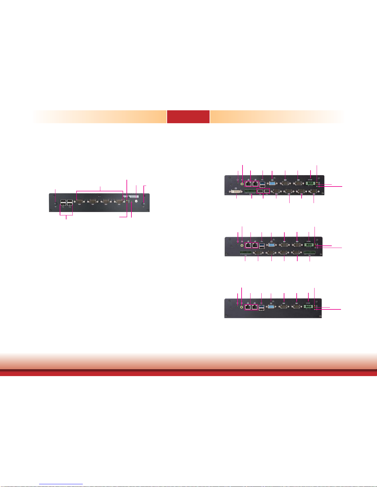
Front Panel I/O Ports
The front panel I/O ports consist of the followings:
• 4 RS232/422/485 COM ports
• 4 USB 2.0 (Type A) ports
• 2 Wi-Fi module antenna holes
• 1 Alert LED
• 1 HDD LED
• 1 reset button
• 1 power button
Alert LED
HDD LED
Reset
Power
USB
Wi-Fi Module
Antenna Hole
Wi-Fi Module
Antenna Hole
COM 1~4
USB Ports
USB 4-5
USB 6-7
USB 4
USB 5
USB 6
USB 7
The USB device allows data exchange between your computer and a wide range of simultaneously accessible external Plug and Play peripherals.
The system board is equipped with four onboard USB 2.0 ports (USB 4-5/6-7) at the front
panel I/O ports of the system chassis and then insert the USB port cables to a connector.
BIOS Setting
Configure the onboard USB in the Advanced menu (“USB Configuration” submenu) of the
BIOS. Refer to chapter 7 for more information.
Driver Installation
You may need to install the proper drivers in your system operation to use the USB device.
Refer to your operating system’s manual or documentation for more information.
Important:
If you are using the Wake-On-USB Keyboard/Mouse function for 2 USB ports, the
+5V_standby power source of your power supply must support ≥1.5A. For 3 or more
USB ports, the +5V_standby power source of your power supply must support ≥2A.
USB 2.0
Page 35

35
Chapter 5 Ports and Connectors
Chapter 5
www.dfi .com
COM (Serial) Ports
Wake-On-USB Keyboard/Mouse
The Wake-On-USB Keyboard/Mouse function allows you to use a USB keyboard or USB mouse
to wake up a system from the S3 (STR - Suspend To RAM) state. To use this function:
• Jumper Setting
JP10 (for USB 4-5) and JP11 (for USB 6-7) must be set to “2-3 On: +5V_standby”. Refer to
“USB Power Select” in chapter 4 for more information.
COM 3
COM 4
COM 1
COM 2
COM 1COM 2COM 3COM 4
COM 1 to COM 4:
RS232/422/485
The pin functions of COM port 1 to COM port 4 will vary according to jumpers’ setting. These
jumpers allow you to configure the Serial COM ports to RS232, RS422 (Full Duplex) or RS485.
Refer to “COM 1/COM 2/COM 3/COM 4 RS232/422/485 Select” and “COM 1/COM 2/COM 3/
COM 4 RS232/Power Select“ in chapter 4 for more information.
The serial ports are asynchronous communication ports with 16C550A-compatible UARTs that
can be used with modems, serial printers, remote display terminals, and other serial devices.
Connecting External Serial Ports
Your COM port may come mounted on a card-edge bracket. Install the card-edge bracket to
an available slot at the rear of the system chassis then insert the serial port cable to the COM
connector. Make sure the colored stripe on the ribbon cable is aligned with pin 1 of the COM
connector.
BIOS Setting
Configure the serial COM ports in the Advanced menu (“SIO NUVOTON6106D” submenu) of
the BIOS. Refer to the chapter 7 for more information.
Operation
Environment
for Customers
DOS Windows 7 Windows 8.x Linux
OS Selection
in the BIOS
Advanced Menu
Windows Linux
Available USB
ports
All
When installing Windows 7 fi rst
time, only native USB 2.0 ports
can work. Please refer to the
USB type in table 2 below.
All All
Table 1. OS Selection
Model Name BT263
USB 3.0
Native
USB 7
HSIC port 3
USB 0
Native
USB 8
HSIC port 0_EXC
USB 1
Native
USB 9
HSIC port 1_EXC
USB 2
Native (share with Mini PCIe)
USB 10
HSIC port 2
USB 3
Native (share with PCIe)
USB 11
HSIC port 3
USB 4
HSIC port 0
USB 5
HSIC port 1
USB 6
HSIC port 2
Table 2. The Type of USB Ports
Important:
When installing Windows 7, only native USB 2.0 devices (USB port 0 to USB port 3)
can operate under DOS mode. Please refer to the following tables for more infomation
on the type of USB ports.
Page 36

36
Chapter 5 Ports and Connectors
Chapter 5
www.dfi .com
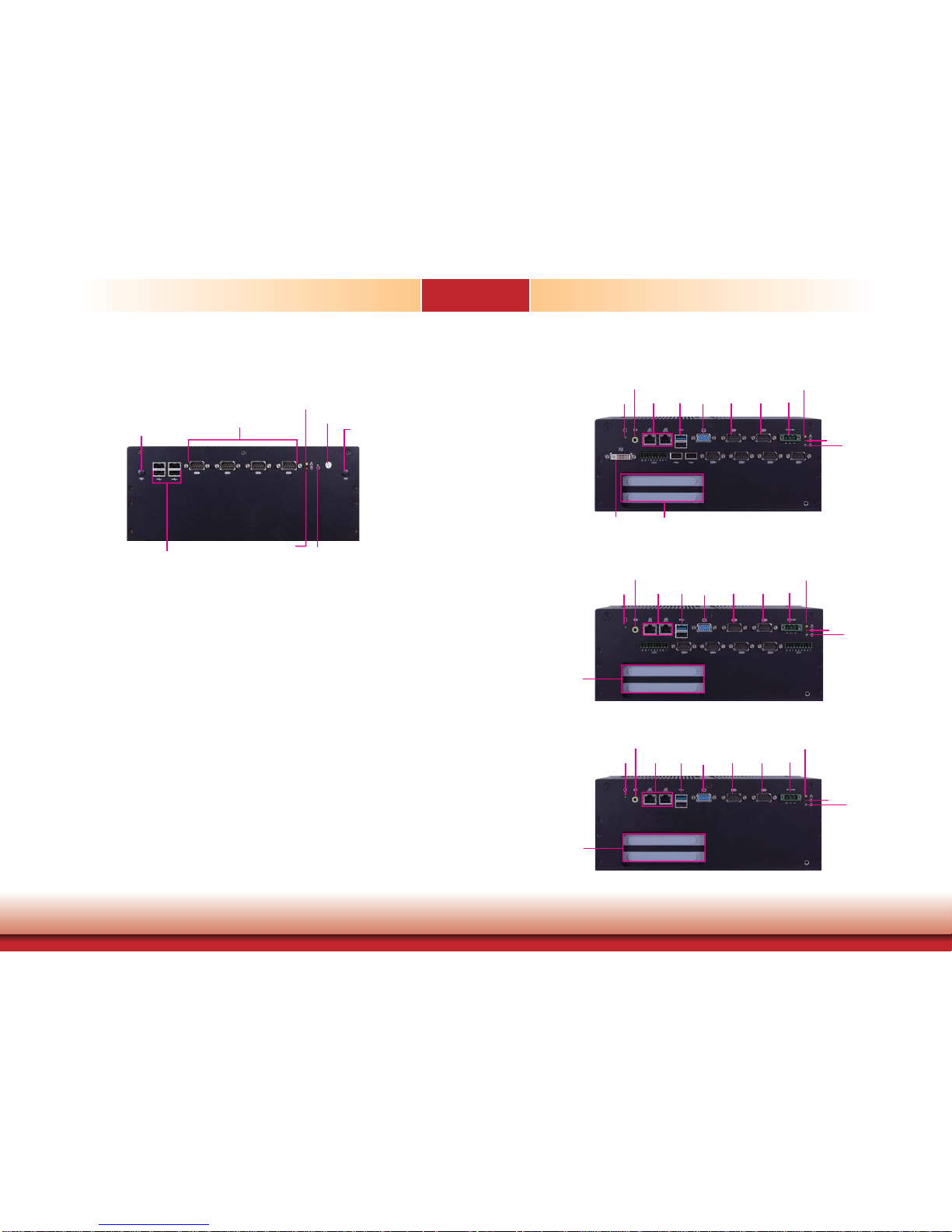
Rear Panel I/O Ports
EC200-BT
EC200-BTA881 Rear View
COM7
COM8
COM9
COM10USB
GPIO
Power
HDD
Alert
DVI
(DVI-D signal)
DC-in
COM5
COM6
VGAUSB
LAN
Speaker-out
Reset
EC200-BTAG60 Rear View
GPIO COM7COM8COM9 GPIOCOM10
Power
DC-inCOM5COM6VGAUSBLAN
Speaker-out
Reset
Power
HDD
Alert
DC-inCOM5COM6VGAUSBLAN
Speaker-out
Reset
EC200-BT6060 Rear View
HDD
Alert
Note:
1. When COM 1 RS232/422/485 is selected, JP23 and JP24 must be set in accordance
to JP15.
2. When COM 2 RS232/422/485 is selected, JP25 and JP26 must be set in accordance
to JP17.
3. When COM 3 RS232/422/485 is selected, JP27 and JP28 must be set in accordance
to JP19.
4. When COM 4 RS232/422/485 is selected, JP29 and JP30 must be set in accordance
to JP21.
5. To make the RS485 auto flow control function work on COM 1 to COM 4, please
set either 8 data bits + 1 stop bit or one of the following settings:
(1) 8 data bits + 1 parity bit + 1 stop bit
(2) 8 data bits + 1 parity bit + 2 stop bits
(3) 8 data bits + 2 stop bits
Page 37

37
Chapter 5 Ports and Connectors
Chapter 5
www.dfi .com
EC210-BT
EC210-BTA881 Rear View
COM7COM8COM9COM10USBGPIO
Power
HDD
Alert
DVI
(DVI-D signal)
DC-in
COM5COM6VGAUSB
LAN
Speaker-out
Reset
PCI Slot
EC210-BTAG60 Rear View
GPIO
COM7COM8COM9 GPIOCOM10
PCI Slot
Power
HDD
Alert
DC-in
COM5COM2VGAUSB
LAN
Speaker-out
Reset
Power
HDD
Alert
DC-in
COM1COM2VGAUSB
LAN
Speaker-out
Reset
EC210-BT6060 Rear View
PCI Slot
The rear panel I/O ports consist of the followings:
EC200 - BTA881
• 1 DC-in power jack: 3-pole terminal block
• 1 Speaker-out: 2W 3.5mm audio jack
• 1 DVI (DVI-D signal)
• 1 VGA: DB-15 D-sub
• 2 RJ45 LAN ports
• 2 RS232 Serial COM ports
• 4 RS232/422/485 Serial COM ports
• 1 USB 3.0 (Type A) port
• 3 USB 2.0 (Type A) ports
• 1 8-bit GPIO: 9-pole terminal block
• 1 Reset button
• 1 Power LED
• 1 HDD LED
• 1 Alert LED
EC200 - BTAG60
• 1 DC-in power jack: 3-pole terminal block
• 1 Speaker-out: 2W 3.5mm audio jack
• 1 VGA: DB-15 D-sub
• 2 RJ45 LAN ports
• 2 RS232 Serial COM ports
• 4 RS232/422/485 Serial COM ports
• 1 USB 3.0 (Type A) port
• 1 USB 2.0 (Type A) port
• 2 8-bit GPIO: 9-pole terminal block
• 1 Reset button
• 1 Power LED
• 1 HDD LED
• 1 Alert LED
EC200 - BT6060
• 1 DC-in power jack: 3-pole terminal block
• 1 Speaker-out: 2W 3.5mm audio jack
• 1 VGA: DB-15 D-sub
• 2 RJ45 LAN ports
• 2 RS232 Serial COM ports
• 1 USB 3.0 (Type A) port
• 1 USB 2.0 (Type A) port
• 1 Reset button
• 1 Power LED
• 1 HDD LED
• 1 Alert LED
Page 38

38
Chapter 5 Ports and Connectors
Chapter 5
www.dfi .com
EC220/EC221-BT
EC220/EC221-BTA881 Rear View
PCI / PCIe x16
(x1 signal) slot
COM7COM8COM9COM10USB USB
GPIO
Power
HDD
Alert
DVI
(DVI-D signal)
DC-inCOM5COM6VGAUSBLAN
Speaker-out
Reset
EC220/EC221-BTAG60 Rear View
PCI / PCIe x16
(x1 signal) slot
Power
HDD
Alert
DC-inCOM5COM6VGAUSBLAN
Speaker-out
Reset
GPIOGPIO
COM7COM8COM9COM10
EC220/EC221-BT6060 Rear View
Power
DC-inCOM5COM6VGAUSBLAN
Speaker-out
Reset
HDD
Alert
PCI / PCIe x16
(x1 signal) slot
The rear panel I/O ports consist of the followings:
EC210 - BTA881
• 1 DC-in power jack: 3-pole terminal block
• 1 Speaker-out: 2W 3.5mm audio jack
• 1 DVI (DVI-D signal)
• 1 VGA: DB-15 D-sub
• 2 RJ45 LAN ports
• 2 RS232 Serial COM ports
• 4 RS232/422/485 Serial COM ports
• 1 USB 3.0 (Type A) port
• 3 USB 2.0 (Type A) ports
• 1 8-bit GPIO: 9-pole terminal block
• 1 Reset button
• 1 Power LED
• 1 HDD LED
• 1 Alert LED
EC210 - BTAG60
• 1 DC-in power jack: 3-pole terminal block
• 1 Speaker-out: 2W 3.5mm audio jack
• 1 VGA: DB-15 D-sub
• 2 RJ45 LAN ports
• 2 RS232 Serial COM ports
• 4 RS232/422/485 Serial COM ports
• 1 USB 3.0 (Type A) port
• 1 USB 2.0 (Type A) port
• 2 8-bit GPIO: 9-pole terminal block
• 1 Reset button
• 1 Power LED
• 1 HDD LED
• 1 Alert LED
EC210 - BT6060
• 1 DC-in power jack: 3-pole terminal block
• 1 Speaker-out: 2W 3.5mm audio jack
• 1 VGA: DB-15 D-sub
• 2 RJ45 LAN ports
• 2 RS232 Serial COM ports
• 1 USB 3.0 (Type A) port
• 1 USB 2.0 (Type A) port
• 1 Reset button
• 1 Power LED
• 1 HDD LED
• 1 Alert LED
Page 39

39
Chapter 5 Ports and Connectors
Chapter 5
www.dfi .com
9~36V DC-in
This jack provides maximum of 60W power and is considered a low power solution. Connect
a DC power cord to this jack. Use a power adapter within 9~36V DC output voltage. Using a
voltage out of the range 9~36V may fail to boot the system or cause damage to the system
board.
DC-in
The rear panel I/O ports consist of the followings:
EC220/EC221 - BTA881
• 1 DC-in power jack: 3-pole terminal block
• 1 Speaker-out: 2W 3.5mm audio jack
• 1 DVI (DVI-D signal)
• 1 VGA: DB-15 D-sub
• 2 RJ45 LAN ports
• 2 RS232 Serial COM ports
• 4 RS232/422/485 Serial COM ports
• 1 USB 3.0 (Type A) port
• 3 USB 2.0 (Type A) ports
• 1 8-bit GPIO: 9-pole terminal block
• 1 Reset button
• 1 Power LED
• 1 HDD LED
• 1 Alert LED
EC220/EC221 - BTAG60
• 1 DC-in power jack: 3-pole terminal block
• 1 Speaker-out: 2W 3.5mm audio jack
• 1 VGA: DB-15 D-sub
• 2 RJ45 LAN ports
• 2 RS232 Serial COM ports
• 4 RS232/422/485 Serial COM ports
• 1 USB 3.0 (Type A) port
• 1 USB 2.0 (Type A) port
• 2 8-bit GPIO: 9-pole terminal block
• 1 Reset button
• 1 Power LED
• 1 HDD LED
• 1 Alert LED
EC220/EC221 - BT6060
• 1 DC-in power jack: 3-pole terminal block
• 1 Speaker-out: 2W 3.5mm audio jack
• 1 VGA: DB-15 D-sub
• 2 RJ45 LAN ports
• 2 RS232 Serial COM ports
• 1 USB 3.0 (Type A) port
• 1 USB 2.0 (Type A) port
• 1 Reset button
• 1 Power LED
• 1 HDD LED
• 1 Alert LED
Page 40

40
Chapter 5 Ports and Connectors
Chapter 5
www.dfi .com
VGA Port
VGA Port
The VGA port is used for connecting a VGA monitor. Connect the monitor’s 15-pin D-shell cable
connector to the VGA port. After you plug the monitor’s cable connector into the VGA port,
gently tighten the cable screws to hold the connector in place.
BIOS Setting
Configure the display devices in the Advanced menu (“Video Configuration” submenu) of the
BIOS. Refer to the chapter 7 for more information.
Driver Installation
Install the graphics driver. Refer to the chapter 8 for more information.
VGA
Speaker-out
This speaker-out jack is used to connect a headphone or external speakers.
Speaker-out
Page 41

41
Chapter 5 Ports and Connectors
Chapter 5
www.dfi .com
RJ45 LAN Ports
Features
• 2 Intel® WGI210AT PCI Express Gigabit Ethernet controllers
The LAN ports allow the system board to connect to a local area network by means of a network hub.
Driver Installation
Install the LAN drivers. Refer to the chapter 8 for more information.
LAN 1
LAN 2
LAN 1 LAN 2
DVI Port
DVI Port
The DVI port is used to connect an LCD monitor. This port supports DVI-D signal only.
Connect the display device’s cable to the DVI port. After plugging the cable connector into the
port, gently tighten the cable screws to hold the connector in place.
BIOS Setting
Configure the display devices in the Advanced menu (“Video Configuration” submenu) of the
BIOS. Refer to the chapter 7 for more information.
Driver Installation
Install the graphics driver. Refer to the chapter 8 for more information.
Page 42

42
Chapter 5 Ports and Connectors
Chapter 5
www.dfi .com
Wake-On-USB Keyboard/Mouse
The Wake-On-USB Keyboard/Mouse function allows you to use a USB keyboard or USB mouse
to wake up a system from the S3 (STR - Suspend To RAM) state. To use this function:
• Jumper Setting
JP1 (for USB 0-1) must be set to “2-3 On: +5V_standby”. Refer to “USB Power Select” in
chapter 4 for more information.
Operation
Environment
for Customers
DOS Windows 7 Windows 8.x Linux
OS Selection
in the BIOS
Advanced Menu
Windows 8.x Windows 7 Windows 8.x Windows 8.x
Available USB
ports
All
When installing Windows 7 fi rst
time, only native USB 2.0 ports
can work. Please refer to the
USB type in table 2 below.
All All
Table 1. OS Selection
Model Name BT263
USB 3.0
Native
USB 7
HSIC port 3
USB 0
Native
USB 8
HSIC port 0_EXC
USB 1
Native
USB 9
HSIC port 1_EXC
USB 2
Native (share with Mini PCIe)
USB 10
HSIC port 2
USB 3
Native (share with PCIe)
USB 11
HSIC port 3
USB 4
HSIC port 0
USB 5
HSIC port 1
USB 6
HSIC port 2
Table 2. The Type of USB Ports
Important:
When installing Windows 7, only native USB 2.0 devices (USB port 0 to USB port 3)
can operate under DOS mode. Please refer to the following tables for more infomation
on the type of USB ports.
USB 0-1
The USB device allows data exchange between your computer and a wide range of simultaneously accessible external Plug and Play peripherals.
The system board is equipped with one onboard USB 3.0 port (USB 0) and one onboard USB
2.0 port (USB 1) at the rear panel I/O ports of the system chassis and then insert the USB
port cables to a connector.
BIOS Setting
Configure the onboard USB in the Advanced menu (“USB Configuration” submenu) of the
BIOS. Refer to chapter 7 for more information.
Driver Installation
You may need to install the proper drivers in your system operation to use the USB device.
Refer to your operating system’s manual or documentation for more information.
USB Ports
Important:
If you are using the Wake-On-USB Keyboard/Mouse function for 2 USB ports, the
+5V_standby power source of your power supply must support ≥1.5A. For 3 or more
USB ports, the +5V_standby power source of your power supply must support ≥2A.
USB 0
USB 1
USB 2.0
USB 3.0
Page 43

43
Chapter 5 Ports and Connectors
Chapter 5
www.dfi .com
DCD-
TXD
RXD
DTR-
GND
123
45
RTS-
RI-
DSR-
CTS-
6
7
8
9
COM (Serial) Ports
COM 5
COM 6
COM 5 and COM 6 are fixed at RS232.
The serial ports are asynchronous communication ports with 16C550A-compatible UARTs that
can be used with modems, serial printers, remote display terminals, and other serial devices.
Connecting External Serial Ports
Your COM port may come mounted on a card-edge bracket. Install the card-edge bracket to
an available slot at the rear of the system chassis then insert the serial port cable to the COM
connector. Make sure the colored stripe on the ribbon cable is aligned with pin 1 of the COM
connector.
BIOS Setting
Configure the serial COM ports in the Advanced menu (“SIO NUVOTON6106D” submenu) of
the BIOS. Refer to the chapter 7 for more information.
COM 5 and COM 6:
RS232
8-bit GPIO
The Digital I/O connector provides powering-on function to an external device that is connected to this connector.
Pins Pin Assignment
1
DIO1
2
DIO2
3
DIO3
4
DIO4
5
DIO5
6
DIO6
7
DIO7
8
DIO8
G
GND
Page 44

44
Chapter 5 Ports and Connectors
Chapter 5
www.dfi .com
Front Panel Connector
HDD-LED
RESET-SW
PWR-LED
PWR-BTN
12
11
2
1
Front
Panel
HDD-LED - HDD LED
This LED will light when the hard drive is being accessed.
RESET-SW - Reset Switch
This switch allows you to reboot without having to power off the system.
PWR-BTN - Power Switch
This switch is used to power on or off the system.
PWR-LED - Power/Standby LED
When the system’s power is on, this LED will light. When the system is in the S1 (POS - Power
On Suspend) state, it will blink every second. When the system is in the S3 (STR - Suspend To
RAM) state, it will blink every 4 seconds.
Pin Pin Assignment Pin Pin Assignment
HDD-LED
3 HDD Power
PWR-LED
2 LED Power
5 Signal 4 LED Power
RESET-SW
7 Ground 6 Signal
9 RST Signal
PWR-BTN
8 Ground
11 N.C. 10 Signal
I/O Connectors
Serial ATA Connectors
Serial ATA Power Connectors
• 2 Serial ATA 2.0 ports with data transfer rate up to 3Gb/s
• Integrated Advanced Host Controller Interface (AHCI) controller
The Serial ATA connector is used to connect the Serial ATA device. Connect one end of the Serial ATA data cable to a SATA connector and the other end to your Serial ATA device.
The SATA power connector supplies power to the SATA drive. Connect one end of the provided
power cable to the SATA power connector and the other end to your storage device.
BIOS Setting
Configure the Serial ATA drives in the Advanced menu (“SATA Configuration” submenu) of the
BIOS. Refer to chapter 7 for more information.
Features
7
RXN
GND
TXP
TXN
GND
1
RXP
GND
SATA 1
SATA Power 1
SATA 2.0 3Gb/s
+12V
+5V
Ground
1
Ground
4
SATA Power 0
7
RXN
GND
TXP
TXN
GND
1
RXP
GND
SATA 0
Note:
SATA port 0 provides adequate space for SATA DOM.
Page 45

45
Chapter 5 Ports and Connectors
Chapter 5
www.dfi .com
PS/2 Keyboard/Mouse Connector
Important:
The 5V_standby power source of your power supply must support ≥720mA.
The Keyboard/Mouse connector is used to connect PS/2 keyboard and PS/2 mouse by means
of a PS/2 cable. Connect one end of the cable to the Keyboard/Mouse connector. The other
ends are used to connect a PS/2 keyboard and a PS/2 mouse.
PS/2 keyboard port
PS/2 mouse port
Connect to the board’s Keyboard/Mouse
connector
Wake-On-PS/2 Keyboard/Mouse
The Wake-On-PS/2 Keyboard/Mouse function allows you to use the PS/2 keyboard or PS/2
mouse to power-on the system. To use this function:
• Jumper Setting
JP13 must be set to “2-3 On: 5V_standby”. Refer to “PS/2 Keyboard/Mouse Power Select”
in this chapter for more information.
1
10
KB CLK
GND
NC
MS CLK
MS DATA
CHASSIS GND
GND
+5V_STB
KB DATA
+5V_STB
2
9
PS/2
KB/MS
Page 46

46
Chapter 5 Ports and Connectors
Chapter 5
www.dfi .com
USB Connectors
USB 10-11
USB 11
(optional)
USB 2.0
10
VCC
Key
VCC
DataData+
GND
N.C.
9
12
DataData+
GND
The USB device allows data exchange between your computer and a wide range of simultaneously accessible external Plug and Play peripherals.
The system board is equipped with one connector for two USB 2.0 ports (USB 10-11) and one
optional USB 2.0 port (USB 11). The 10-pin connector allows you to connect 2 additional USB
2.0/1.1 ports (USB 10-11). The additional USB ports may be mounted on a card-edge bracket.
Install the card-edge bracket to an available slot at the rear of the system chassis and then
insert the USB port cables to a connector.
BIOS Setting
Configure the onboard USB in the Advanced menu (“USB Configuration” submenu) of the
BIOS. Refer to chapter 7 for more information.
Driver Installation
You may need to install the proper drivers in your system operation to use the USB device.
Refer to your operating system’s manual or documentation for more information.
Wake-On-USB Keyboard/Mouse
The Wake-On-USB Keyboard/Mouse function allows you to use a USB keyboard or USB mouse
to wake up a system from the S3 (STR - Suspend To RAM) state. To use this function:
• Jumper Setting
JP9 (for USB 10-11) must be set to “2-3 On: +5V_standby”. Refer to “USB Power Select” in
chapter 4 for more information.
Operation
Environment
for Customers
DOS Windows 7 Windows 8.x Linux
OS Selection
in the BIOS
Advanced Menu
Windows 8.x Windows 7 Windows 8.x Windows 8.x
Available USB
ports
All
When installing Windows 7 fi rst
time, only native USB 2.0 ports
can work. Please refer to the
USB type in table 2 below.
All All
Table 1. OS Selection
Table 2. The Type of USB Ports
Important:
1. If you are using the Wake-On-USB Keyboard/Mouse function for 2 USB ports, the
+5V_standby power source of your power supply must support ≥1.5A. For 3 or
more USB ports, the +5V_standby power source of your power supply must support ≥2A.
2. When installing Windows 7, only native USB 2.0 devices (USB port 0 to USB port 3)
can operate under DOS mode. Please refer to the following tables for more infomation on the type of USB ports.
Model Name BT263
USB 3.0
Native
USB 7
HSIC port 3
USB 0
Native
USB 8
HSIC port 0_EXC
USB 1
Native
USB 9
HSIC port 1_EXC
USB 2
Native (share with Mini PCIe)
USB 10
HSIC port 2
USB 3
Native (share with PCIe)
USB 11
HSIC port 3
USB 4
HSIC port 0
USB 5
HSIC port 1
USB 6
HSIC port 2
Page 47

47
Chapter 5 Ports and Connectors
Chapter 5
www.dfi .com
Parallel Connector
21
26 25
Parallel
The 25-pin connector is used to connect an external parallel port. The parallel port connects
your PC to a parallel printer. It supports SPP, ECP and EPP.
SPP
(Standard Parallel Port)
Allows normal speed operation but in one
direction only.
ECP
(Extended Capabilities Port)
Allows parallel port to operate in bidirectional
mode and at a speed faster than the SPP’s data
transfer rate.
EPP
(Enhanced Parallel Port)
Allows bidirectional parallel port operation at
maximum speed.
Digital I/O and/or Power Connector
The 8-bit Digital I/O connector provides powering-on function to external devices that are connected to the connector. The pin functions of the 8-bit digital I/O connector are listed below.
Pins Pin Assignment Pins Pin Assignment
1
GND
2
+12V
3
DIO7
4
+12V
5
DIO6
6
GND
7
DIO5
8
+5V
9
DIO4
10
+5V
11
DIO3
12
GND
13
DIO2
14
+5V_Standby
15
DIO1
16
+5V_Standby
17
DIO0
18
GND
19
GND
Digital I/O
19
12
Page 48

48
Chapter 5 Ports and Connectors
Chapter 5
www.dfi .com
Chassis Intrusion Connector
The board supports the chassis intrusion detection function. Connect the chassis intrusion
sensor cable from the chassis to this connector. When the system’s power is on and a chassis
intrusion occurred, an alarm will sound. When the system’s power is off and a chassis intrusion
occurred, the alarm will sound only when the system restarts.
12
Ground
Signal
Chassis
Intrusion
Front Audio Connector
The front audio connector allows you to connect to the second line-out jack that is at the front
panel of your system.
Driver Installation
Install the audio driver. Refer to the chapter 8 for more information.
Front
Audio
1
Mic2-L
Line2-R
Front_IO_Sense
GND
Presence Signal
Key
2
10
Mic2-JD
Line2-JD
9
Mic2-R
Line2-L
Page 49

49
Chapter 5 Ports and Connectors
Chapter 5
www.dfi .com
S/PDIF Connector
S/PDIF
1
5
+5V
Key
SPDIF out
Ground
SPDIF_in
The S/PDIF connector is used to connect an external S/PDIF port. Your S/PDIF port may be
mounted on a card-edge bracket. Install the card-edge bracket to an available slot at the rear
of the system chassis then connect the audio cable to the S/PDIF connector. Make sure pin 1
of the audio cable is aligned with pin 1 of the S/PDIF connector.
Cooling Fan Connector
The fan connector is used to connect the cooling fan. The cooling fan will provide adequate
airflow throughout the chassis to prevent overheating the CPU and system board components.
BIOS Setting
The Advanced menu (“SIO NUVOTON6106D” submenu) of the BIOS will display the current
speed of the cooling fans. Refer to chapter 7 for more information.
1
Ground
Power
Sense
CPU Fan
Page 50

50
Chapter 5 Ports and Connectors
Chapter 5
www.dfi .com
LPC Connector
2
1
12
11
LPC
The LPC connector is used for the debug function and its pin functions are listed below.
Pins Pin Assignment Pins Pin Assignment
1
CLK
2
LAD1
3
RST#
4
LAD0
5
FRAME#
6
VCC_+3V
7
LAD3
8
GND
9
LAD2
10
x
11
SERIRQ
12
48MHz
SMBus Connector
The SMBus (System Management Bus) connector is used to connect SMBus devices. It is a
multiple device bus that allows multiple chips to connect to the same bus and enable each one
to act as a master by initiating data transfer.
SMBus
GND
+3.3V_standby
SMBUS Data
SMBUS Clock
NC SMBUS_Alert
12
56
Page 51

51
Chapter 5 Ports and Connectors
Chapter 5
www.dfi .com
Expansion Slots
EXC Slot
The EXC interface is used to install an EXC card for I/O expansion.
Mini PCI Express Slot
The Mini PCI Express slot on the system board is used to install one half and/or full size Mini
PCIe card such as network cards or other cards that comply to the mini PCI Express specifications into the mini PCI Express slot.
DFI Proprietary Extension Bus
The DFI Proprietary Extension Bus gold finger is used for customized expansion (PCI or Mini
PCIe) via a riser card.
Mini PCIe
EXC
DFI Proprietary
Extension Bus
DFI Proprietary Extension Bus
Pins Pin Assignment Pins Pin Assignment
A1
GND
B1
+12V
A2
+12V
B2
+12V
A3
+12V
B3
+12V
A4
GND
B4
GND
A5
+5V
B5
SMB_CLK
A6
+5V
B6
SMB_DATA
A7
+5V
B7
GND
A8
+5V
B8
+3V3
A9
+3V3
B9
NC
A10
+3V3
B10
+3VDU
A11
RESET-
B11
PCIE_WAKE-
A12
GND
B12
PME-
A13
CLK+
B13
GND
A14
CLK-
B14
TX+
A15
GND
B15
TX-
A16
RX+
B16
GND
A17
RX-
B17
NC
A18
GND
B18
GND
Page 52

52
Chapter 5 Ports and Connectors
Chapter 5
www.dfi .com
The lithium ion battery powers the real-time clock and CMOS memory. It is an auxiliary source
of power when the main power is shut off.
Safety Measures
• Danger of explosion if battery incorrectly replaced.
• Replace only with the same or equivalent type recommend by the manufacturer.
• Dispose of used batteries according to local ordinance.
Battery
Battery
Standby Power LED
This LED will blink when the system is in the standby mode. It indicates that there is power
on the system board. Power-off the PC and then unplug the power cord prior to installing any
devices. Failure to do so will cause severe damage to the motherboard and components.
Standby Power LED
Standby Power LED
Page 53

www.dfi .com
53
Chapter 6 Mounting Options
Chapter 6
Chapter 6 - Mounting Option
Wall Mount
The wall mount kit includes the following:
• 2 Wall mount brackets
• 4 Bracket screws
1. The wall mounting holes are located on the bottom side of the system unit.
Mounting hole
2. Use the provided mounting screws to secure the wall mount brackets on each side of the
system unit.
291.60
16.00
Ø3.60
Ø8.50
80.00
40.00
120.00
R2.00
R2.50
Mounting screw
Wall mount
bracket
Wall mount
bracket
Page 54

www.dfi .com
54
Chapter 7 BIOS Setup
Chapter 7
Chapter 7 - BIOS Setup
Overview
The BIOS is a program that takes care of the basic level of communication between the CPU
and peripherals. It contains codes for various advanced features found in this system board.
The BIOS allows you to configure the system and save the configuration in a battery-backed
CMOS so that the data retains even when the power is off. In general, the information stored
in the CMOS RAM of the EEPROM will stay unchanged unless a configuration change has been
made such as a hard drive replaced or a device added.
It is possible that the CMOS battery will fail causing CMOS data loss. If this happens, you need
to install a new CMOS battery and reconfigure the BIOS settings.
Default Configuration
Most of the configuration settings are either predefined according to the Load Optimal Defaults
settings which are stored in the BIOS or are automatically detected and configured without
requiring any actions. There are a few settings that you may need to change depending on
your system configuration.
Entering the BIOS Setup Utility
The BIOS Setup Utility can only be operated from the keyboard and all commands are keyboard commands. The commands are available at the right side of each setup screen.
The BIOS Setup Utility does not require an operating system to run. After you power up the
system, the BIOS message appears on the screen and the memory count begins. After the
memory test, the message “Press DEL to run setup” will appear on the screen. If the message
disappears before you respond, restart the system or press the “Reset” button. You may also
restart the system by pressing the <Ctrl> <Alt> and <Del> keys simultaneously.
Legends
Scroll Bar
When a scroll bar appears to the right of the setup screen, it indicates that there are more
available fields not shown on the screen. Use the up and down arrow keys to scroll through all
the available fields.
Submenu
When ““ appears on the left of a particular field, it indicates that a submenu which contains
additional options are available for that field. To display the submenu, move the highlight to
that field and press <Enter>.
Note:
The BIOS is constantly updated to improve the performance of the system board;
therefore the BIOS screens in this chapter may not appear the same as the actual
one. These screens are for reference purpose only.
Keys Function
Right and Left arrows
Moves the highlight left or right to select a menu.
Up and Down arrows
Moves the hightlight up or down between submenu or fi elds.
<Esc>
Exit to the BIOS Setup Utility.
+ (plus key)
Scrolls forward through the values or options of the highlighted fi eld.
- (minus key)
Scrolls backward through the values or options of the highlighted fi eld.
Tab
Select a fi eld.
<Enter>
Press <Enter> to enter the highlighted submenu.
Page 55

www.dfi .com
55
Chapter 7 BIOS Setup
Chapter 7
Main
The Main menu is the first screen that you will see when you enter the BIOS Setup Utility.
Insyde BIOS Setup Utility Advanced
The Advanced menu allows you to configure your system for basic operation. Some entries are
defaults required by the system board, while others, if enabled, will improve the performance
of your system or let you set some features according to your preference.
Important:
Setting incorrect field values may cause the system to malfunction.
System Time
The time format is <hour>, <minute>, <second>. The time is based on the 24-hour
military-time clock. For example, 1 p.m. is 13:00:00. Hour displays hours from 00 to
23. Minute displays minutes from 00 to 59. Second displays seconds from 00 to 59.
System Date
The date format is <day>, <month>, <date>, <year>. Day displays a day, from Sunday to Saturday. Month displays the month, from January to December. Date displays
the date, from 1 to 31. Year displays the year, from 1980 to 2099.
This is the help for the
hour, minute, second
fi eld. Valid range is from
0 to 23, 0 to 59, 0 to 59.
INCREASE/REDUCE:
+/-.
InsydeH20 Setup Utility
ExitSecurity
F1 Help ↑↓ Select Item F5/F6 Change Values F9 Setup Defaults
Esc Exit ←→ Select Menu Enter Select SubMenu F10 Save and Exit
Project Name
BIOS Version
Processor Type
System Memory Speed
Cache RAM
Total Memory
Channel A - SODIMM 0
Channel B - SODIMM 0
System Time
System Date
BT263
53.200
Intel(R) Atom(TM) CPU E3845 @1.91GHz
1333 MHz
2048 KB
4096 MB
4096 MB
[No Installed]
[20:03:32]
[02/24/2015]
Advanced
Power Boot
Main
Rev. 5.0
PCI Express Confi guration
Settings
PCI Express Confi guration
USB Confi guration
Audio Confi guration
Miscellaneous Confi guration
Security Confi guration
Video Confi guration
SATA Confi guration
SIO NUVOTON6106D
SIO F81216
Main
Advanced
F1 Help ↑↓ Select Item F5/F6 Change Values F9 Setup Defaults
Esc Exit ←→ Select Menu Enter Select SubMenu F10 Save and Exit
InsydeH20 Setup Utility
ExitSecurity Power Boot
Rev. 5.0
Page 56

www.dfi .com
56
Chapter 7 BIOS Setup
Chapter 7
PCI Express Configuration
This section configures settings relevant to PCI Express root ports.
Control the PCI Express
Root Port.
PCI Express Confi guration
PCI Express Root Port 1
PCI Express Root Port 2
PCI Express Root Port 3
PCI Express Root Port 4
Advanced
F1 Help ↑↓ Select Item F5/F6 Change Values F9 Setup Defaults
Esc Exit ←→ Select Menu Enter Select SubMenu F10 Save and Exit
InsydeH20 Setup Utility Rev. 5.0
PCI Express Root Port 1 to PCI Express Root Port 4
This field controls the function of the PCI Express Root Port.
Control the PCI Express
Root Port.
PCI Express Root Port
PCI Express Root Port
PCIE Port Speed
Advanced
F1 Help ↑↓ Select Item F5/F6 Change Values F9 Setup Defaults
Esc Exit ←→ Select Menu Enter Select SubMenu F10 Save and Exit
InsydeH20 Setup Utility Rev. 5.0
<Enabled>
<Auto>
PCI Express Root Port
This field is used to enable or disable the PCI Express Root Port.
PCIE Port Speed
Select the speed of the PCI Express Root Port: Auto, Gen1 or Gen2.
Page 57

www.dfi .com
57
Chapter 7 BIOS Setup
Chapter 7
USB Configuration
This section is used to configure the parameters of the USB device.
USB keyboard/mouse/storage support under UEFI
and DOS environment. It
will supporting UEFI environment only if set to
UEFI Only.
USB Confi guration
USB BIOS Support
xHCI Mode
Advanced
F1 Help ↑↓ Select Item F5/F6 Change Values F9 Setup Defaults
Esc Exit ←→ Select Menu Enter Select SubMenu F10 Save and Exit
InsydeH20 Setup Utility Rev. 5.0
<Enabled>
<Smart Auto>
USB BIOS Support
This field enables or disables the USB keyboard/mouse/storage support under the UEFI
and DOS environment. It will support the UEFI environment only when it is set to
UEFI Only.
xHCI Mode
This field is used to select the operation mode of xHCI controller.
Important:
When installing Windows 7, only native USB 2.0 devices (USB port 0 to USB port 3)
can operate under DOS mode. Please refer to the following tables for more infomation
on the type of USB ports.
Operation
Environment
for Customers
DOS Windows 7 Windows 8.x Linux
OS Selection
in the BIOS
Advanced Menu
Windows Linux
Available USB
ports
All
When installing Windows 7 fi rst
time, only native USB 2.0 ports
can work. Please refer to the
USB type in table 2 below.
All All
Table 1. OS Selection
Table 2. The Type of USB Ports
Model Name BT263
USB 3.0
Native
USB 7
HSIC port 3
USB 0
Native
USB 8
HSIC port 0_EXC
USB 1
Native
USB 9
HSIC port 1_EXC
USB 2
Native (share with Mini PCIe)
USB 10
HSIC port 2
USB 3
Native (share with PCIe)
USB 11
HSIC port 3
USB 4
HSIC port 0
USB 5
HSIC port 1
USB 6
HSIC port 2
Page 58

www.dfi .com
58
Chapter 7 BIOS Setup
Chapter 7
Audio Configuration
This section is used to configure the audio settings.
Enable/Disable Internal
HDMI codec for Azalia.
Audio Confi guration
Azalia HDMI Codec
Advanced
F1 Help ↑↓ Select Item F5/F6 Change Values F9 Setup Defaults
Esc Exit ←→ Select Menu Enter Select SubMenu F10 Save and Exit
InsydeH20 Setup Utility Rev. 5.0
<Enabled>
Azalia HDMI Codec
Enables or disables the internal HDMI codec for Azalia.
Miscellaneous Configuration
This section enables or disables Misc. features.
High Performance Event
Timer Support in Windows
XP. Enabled this feature,
the HPET table will be
add-into ACPI Tables.
Miscellaneous Confi guration
HPET - HPET Support
OS Selection
State After G3
Advanced
F1 Help ↑↓ Select Item F5/F6 Change Values F9 Setup Defaults
Esc Exit ←→ Select Menu Enter Select SubMenu F10 Save and Exit
InsydeH20 Setup Utility Rev. 5.0
<Enabled>
<Windows>
<Always Power off>
HPET - HPET Support
Enable or disable the high performance event timer support in Windows XP. When
enabling this feature, the HPET table will be added into ACPI tables.
OS Selection
Select the OS support: Linux or Windows.
State After G3
Specify what state to go when the power is reapplied after a power failure. (G3 state).
Page 59

www.dfi .com
59
Chapter 7 BIOS Setup
Chapter 7
Security Configuration
This section only displays the security condition.
TXE Confi guration
TXE FW Version
TXE FW Capabilities
TXE FW Features
TXE FW OEM Tag
TXE Firmware Mode
Advanced
F1 Help ↑↓ Select Item F5/F6 Change Values F9 Setup Defaults
Esc Exit ←→ Select Menu Enter Select SubMenu F10 Save and Exit
InsydeH20 Setup Utility Rev. 5.0
1.0.2.1067
A0001040
A0001040
00000000
Normal
Video Configuration
This section configures the video settings.
Enable: Enable Integrated
Graphics Device (IGD)
when selected as the Primary Video Adapter. Disable: Always disable IGD.
IGD Confi guration
Integrated Graphics Device
Primary Display
Advanced
F1 Help ↑↓ Select Item F5/F6 Change Values F9 Setup Defaults
Esc Exit ←→ Select Menu Enter Select SubMenu F10 Save and Exit
InsydeH20 Setup Utility Rev. 5.0
<Enabled>
<Auto>
Integrated Graphics Device
Enable or disable the function of integrated graphics device.
Primary Display
Select the primary display device: IGD or PCI graphics device.
Page 60

www.dfi .com
60
Chapter 7 BIOS Setup
Chapter 7
SATA Configuration
This section is designed to select the SATA controller and the type of hard disk drive which are
insalled in your system unit.
DISABLED: Disables
SATA controller.
ENABLED: Enables SATA
conroller.
SATA Controller
Chipset SATA Mode
SATA Speed
Serial ATA Port 0
Serial ATA Port 1
Advanced
F1 Help ↑↓ Select Item F5/F6 Change Values F9 Setup Defaults
Esc Exit ←→ Select Menu Enter Select SubMenu F10 Save and Exit
InsydeH20 Setup Utility Rev. 5.0
<Enabled>
<AHCI>
<Gen2>
[ST500DM002-1BD142]
[Not Installed]
Serial ATA Port 0
This field configures the function of the Serial ATA Port 0.
Serial ATA Port 0 [ST500DM002-1BD142]
Security Mode: Uninstall
Advanced
F1 Help ↑↓ Select Item F5/F6 Change Values F9 Setup Defaults
Esc Exit ←→ Select Menu Enter Select SubMenu F10 Save and Exit
InsydeH20 Setup Utility Rev. 5.0
SATA Controller
Enable or disable the Serial ATA Port.
Chipset SATA Mode
Select the SATA mode. The item is fixed at the AHCI mode.
SATA Speed
Select the SATA speed: Gen 1 or Gen 2.
Page 61

www.dfi .com
61
Chapter 7 BIOS Setup
Chapter 7
SIO NUVOTON6106D
This section configures the system super I/O chip parameters.
Enable/Disable Smart Fan.
SIO NUVOTON6106D
Smart Fan Control
Serial Port 1
Base I/O Address
Interrupt
RS485 Auto Flow Control
Serial Port 2
Base I/O Address
Interrupt
RS485 Auto Flow Control
Serial Port 3
Base I/O Address
Interrupt
RS485 Auto Flow Control
Serial Port 4
Base I/O Address
Interrupt
RS485 Auto Flow Control
Serial Port 5
Base I/O Address
Interrupt
RS485 Auto Flow Control
Serial Port 6
Base I/O Address
Interrupt
RS485 Auto Flow Control
LPT Port A
Base I/O Address
Interrupt
WDT
WDT Mode
COUNTER
Case Open
Hardware Monitor
Advanced
F1 Help ↑↓ Select Item F5/F6 Change Values F9 Setup Defaults
Esc Exit ←→ Select Menu Enter Select SubMenu F10 Save and Exit
InsydeH20 Setup Utility Rev. 5.0
<Enable>
<3F8>
<IRQ10>
<Disable>
<Enable>
<2F8>
<IRQ11>
<Disable>
<Enable>
<3E8>
<IRQ10>
<Disable>
<Enable>
<2E8>
<IRQ11>
<Disable>
<Enable>
<338>
<IRQ10>
<Disable>
<Enable>
<228>
<IRQ11>
<Disable>
<Enable>
<378>
<IRQ10>
<Enable>
<SECOND>
[0]
<Disable>
Serial Port 1 to Serial Port 6
Configure the options to use the serial port.
Disable No configuration
Enable User confi guration
Auto EFI/OS chooses confi guration
LPT Port A
Configure the options to use the LPT port.
Disable No configuration
Enable User confi guration
Auto EFI/OS chooses configuration
RS485 Auto Flow Control
Enable or disable the RS485 auto flow control.
WDT Mode
Select the count mode: minute or second.
Counter
Enter the value for the counter. The time-out counter ranges from 1 to 255 minutes in
the minute mode and from 1 to 255 seconds in the second mode.
Case Open
Enable or disable the case open.
Note:
To make the RS485 auto flow control function work on COM 1 to COM 4, please set
either 8 data bits + 1 stop bit or one of the following settings:
(1) 8 data bits + 1 parity bit + 1 stop bit
(2) 8 data bits + 1 parity bit + 2 stop bits
(3) 8 data bits + 2 stop bits
Page 62

www.dfi .com
62
Chapter 7 BIOS Setup
Chapter 7
CPU Smart Fan Control
Enable or disable the CPU smart fan.
Boundary 1 to Boundary 4
Set the boundary temperature. The range is from 0-127.
Fan Speed Count 1 to Fan Speed Count 4
Set the fan speed. The range is from 0-100%.
Smart Fan Control
This field enables or disables the smart fan control.
CPU Smart Fan Control
CPU Fan Mode
Boundary 1
Boundary 2
Boundary 3
Boundary 4
Fan Speed Count 1
Fan Speed Count 2
Fan Speed Count 3
Fan Speed Count 4
Advanced
F1 Help ↑↓ Select Item F5/F6 Change Values F9 Setup Defaults
Esc Exit ←→ Select Menu Enter Select SubMenu F10 Save and Exit
InsydeH20 Setup Utility Rev. 5.0
<Enable>
<SMART FAN IV>
[30]
[40]
[50]
[60]
[30]
[40]
[50]
[75]
Enable CPU Smart Fan.
Hardware Monitor
This field only displays the hardware monitor status.
Hardware Monitor
Voltage
VCORE
VDDQ
+12V
5V
Temperature
System (
oC/o
F)
CPU (oC/oF)
Fan Speed
CPU FAN
Advanced
F1 Help ↑↓ Select Item F5/F6 Change Values F9 Setup Defaults
Esc Exit ←→ Select Menu Enter Select SubMenu F10 Save and Exit
InsydeH20 Setup Utility Rev. 5.0
0.960 V
1.348 V
12.096 V
5.120 V
30
o
C/86oF
29
o
C/84oF
0 RPM
Page 63

www.dfi .com
63
Chapter 7 BIOS Setup
Chapter 7
SIO F81216
This section configures the system I/O chip parameters.
Confi gure Serial port using
options: [Disable] No Configuration [Enable] User
Confi guration [Auto] EFI/
OS chooses confi guration.
SIO F81216
Serial Port 7
Base I/O Address
Interrupt
RS485 Auto Flow Control
Serial Port 8
Base I/O Address
Interrupt
RS485 Auto Flow Control
Serial Port 9
Base I/O Address
Interrupt
RS485 Auto Flow Control
Serial Port 10
Base I/O Address
Interrupt
RS485 Auto Flow Control
Advanced
F1 Help ↑↓ Select Item F5/F6 Change Values F9 Setup Defaults
Esc Exit ←→ Select Menu Enter Select SubMenu F10 Save and Exit
InsydeH20 Setup Utility Rev. 5.0
<Enable>
<240>
<IRQ3>
<Disable>
<Enable>
<248>
<IRQ4>
<Disable>
<Enable>
<250>
<IRQ5>
<Disable>
<Enable>
<258>
<IRQ7>
<Disable>
Serial Port 7 to Serial Port 10
Configure the options to use the serial port.
Disable No configuration
Enable User confi guration
Auto EFI/OS chooses confi guration
RS485 Auto Flow Control
Enable or disable the RS485 auto flow control.
Enable/Disable TPM Function. This option will automatically return to NoOperation.
TPM 1.2 Status
TPM Operation
Supervisor Password
Set Supervisor Password
Main
Advanced
F1 Help ↑↓ Select Item F5/F6 Change Values F9 Setup Defaults
Esc Exit ←→ Select Menu Enter Select SubMenu F10 Save and Exit
InsydeH20 Setup Utility
ExitSecurity Power Boot
Rev. 5.0
Security
TPM Operation
Enable or disable the TPM function. This option will automatically return to
No-Operation.
Set Supervisor Password
Set the supervisor’s password and the length of the password must be greater than
one character.
Enable and Active
<No operation>
Not installed
Page 64

www.dfi .com
64
Chapter 7 BIOS Setup
Chapter 7
These items control various
CPU parameters.
Advanced CPU Control
Main
Advanced
F1 Help ↑↓ Select Item F5/F6 Change Values F9 Setup Defaults
Esc Exit ←→ Select Menu Enter Select SubMenu F10 Save and Exit
InsydeH20 Setup Utility
ExitSecurity Power Boot
Rev. 5.0
Power
Advanced CPU Control
This section controls various CPU parameters.
Number of cores to enable
in each processor package.
Advanced CPU Control
Active Processor Cores
Turbo Mode
F1 Help ↑↓ Select Item F5/F6 Change Values F9 Setup Defaults
Esc Exit ←→ Select Menu Enter Select SubMenu F10 Save and Exit
InsydeH20 Setup Utility
Power
Rev. 5.0
Active Processor Cores
Number of cores to enable in each processor package.
Turbo Mode
Select the processor turbo mode.
Auto
E
nable the processor to support the turbo mode.
Disabled
Always disable the processor turbo mode.
<ALL>
<Auto>
Page 65

www.dfi .com
65
Chapter 7 BIOS Setup
Chapter 7
Boot
Select boot type to Dual
type, Legacy type or UEFI
type.
Boot Type
Network Stack
PXE Boot Capability
USB Boot
Boot Menu Type
Boot Sequence
Main
Advanced
F1 Help ↑↓ Select Item F5/F6 Change Values F9 Setup Defaults
Esc Exit ←→ Select Menu Enter Select SubMenu F10 Save and Exit
InsydeH20 Setup Utility
ExitSecurity Power Boot
Rev. 5.0
<Dual Boot Type>
<Disabled>
<Disabled>
<Enabled>
<Advance>
Boot Type
Select the boot type. The options are Dual Boot Type, Legacy Boot Type or UEFI Boot
Type.
Network Stack
Network stack support:
Windows 8 BitLocker Unlock.
UEFI IPv4 PXE
Legacy PXE OpROM
USB Boot
Enable or disable the booting for USB boot devices.
Boot Menu Type
Normal
Based on the boot normal priority, it determines the EFI device first or the legacy
device first.
Advance
All boot devices follow the user’s selection sequence.
Boot Sequence
This sequence is used when the system is powered up normally.
Boot Sequence
ST500DM002-1BD142
F1 Help ↑↓ Select Item F5/F6 Change Values F9 Setup Defaults
Esc Exit ←→ Select Menu Enter Select SubMenu F10 Save and Exit
InsydeH20 Setup Utility
Boot
Rev. 5.0
Set the system boot order.
Page 66

www.dfi .com
66
Chapter 7 BIOS Setup
Chapter 7
Exit system srtup and save
your changes.
Exit Saving Changes
Exit Discarding Changes
Load Optimal Defaults
Main
Advanced
F1 Help ↑↓ Select Item F5/F6 Change Values F9 Setup Defaults
Esc Exit ←→ Select Menu Enter Select SubMenu F10 Save and Exit
InsydeH20 Setup Utility
ExitSecurity Power Boot
Rev. 5.0
Exit
Exit Saving Changes
Select this field and then press <Enter> to exit the system setup and save your
changes.
Exit Discarding Changes
Select this field and then press <Enter>to exit the system setup without saving your
changes.
Load Optimal Defaults
Select this field and then press <Enter> to load optimal defaults.
Notice: BIOS SPI ROM
1. The Intel® Management Engine has already been integrated into this system board. Due to
the safety concerns, the BIOS (SPI ROM) chip cannot be removed from this system board
and used on another system board of the same model.
2. The BIOS (SPI ROM) on this system board must be the original equipment from the factory
and cannot be used to replace one which has been utilized on other system boards.
3. If you do not follow the methods above, the Intel
®
Management Engine will not be updated
and will cease to be effective.
Note:
a. You can take advantage of flash tools to update the default configuration of the
BIOS (SPI ROM) to the latest version anytime.
b. When the BIOS IC needs to be replaced, you have to populate it properly onto the
system board after the EEPROM programmer has been burned and follow the
technical person's instructions to confirm that the MAC address should be burned
or not.
Page 67

www.dfi .com
67
Chapter 8 Supported Software
Chapter 8
Chapter 8 - Supported Software
The CD that came with the system board contains drivers, utilities and software applications
required to enhance the performance of the system board.
Insert the CD into a CD-ROM drive. The autorun screen (Mainboard Utility CD) will appear. If
after inserting the CD, “Autorun” did not automatically start (which is, the Mainboard Utility
CD screen did not appear), please go directly to the root directory of the CD and double-click
“Setup”.
Auto Run Page (For Windows 8.1)
Auto Run Page (For Windows 7)
Page 68

www.dfi .com
68
Chapter 8 Supported Software
Chapter 8
Intel Chipset Software Installation Utility
The Intel Chipset Device Software is used for updating Windows
®
INF files so that the Intel
chipset can be recognized and configured properly in the system.
To install the utility, click “Intel Chipset Software Installation Utility” on the main menu.
1. Setup is ready to install the
utility. Click Next.
2. Read the license agreement
then click Yes.
4. After all setup operations are
done, click Next.
3. Go through the readme docu-
ment for more installation tips
then click Next.
5. Click “Yes, I want to restart this
computer now” then click Finish.
Restarting the system will allow the
new software installation to take
effect.
Page 69

www.dfi .com
69
Chapter 8 Supported Software
Chapter 8
Intel HD Graphics Drivers
To install the driver, click “Intel HD Graphics Drivers” on the main menu.
1. Setup is now ready to install
the graphics driver. Click
Next.
By default, the “Automatically run WinSAT and enable the Windows Aero desktop theme” is
enabled. With this enabled, after installing the graphics driver and the system rebooted, the
screen will turn blank for 1 to 2 minutes (while WinSAT is running) before the Windows 7/
Windows 8 desktop appears. The “blank screen” period is the time Windows is testing the
graphics performance.
We recommend that you skip this process by disabling this function then click Next.
2. Read the license agreement
then click Yes.
4. Setup is now installing the
driver. Click Next to continue
.
3. Go through the readme document for system requirements
and installation tips then click
Next.
5. Click “Yes, I want to restart this
computer now” then click Finish.
Restarting the system will allow the
new software installation to take
effect.
Page 70

www.dfi .com
70
Chapter 8 Supported Software
Chapter 8
Intel LAN Drivers
To install the driver, click “Intel LAN Drivers” on the main menu.
1. Setup is ready to install the
driver. Click Next.
2. Click “I accept the terms
in the license agreement”
then click “Next”.
3. Select the program featuers
you want installed then
click Next.
4. Click Install to begin the
installation.
5. After completing installation, click Finish.
Page 71

www.dfi .com
71
Chapter 8 Supported Software
Chapter 8
Kernel Mode Driver Framework (For Windows 7 only)
To install the driver, click “Kernel Mode Driver Framework” on the main menu.
Intel Trusted Execution Engine Driver
To install the driver, click “Intel Trusted Execution Engine Driver” on the main menu.
1. Tick “I accept the terms
in the License Agreement“
and then click “Next.”
2. The step shows the
components which will be
installed. Then, Click Next.
1. Click “Yes“ to install the
update.
2. The update is installed
now.
3. Click “Restart Now“ to
restart your computer when
the installation is complete.
Page 72

www.dfi .com
72
Chapter 8 Supported Software
Chapter 8
3. The step displays the
installing status in the
progress.
4. Click “Finish“ when the
installation is complete.
1. Setup is now ready to install the
audio driver. Click Next.
2. Follow the remainder of the steps
on the screen; clicking “Next”
each time you finish a step.
3. Click “Yes, I want to restart my
computer now” then click Finish.
Restarting the system will allow the
new software installation to take
effect.
Realtek Audio Drivers
To install the driver, click “Realtek Audio Drivers” on the main menu.
Page 73

www.dfi .com
73
Chapter 8 Supported Software
Chapter 8
HW Utility
HW Utility provides information about the board, HW Health, Watchdog, DIO, and Backlight. To
access the utility, click “HW Utility” on the main menu.
2. Click “I accept the terms in the
license agreement” and then click
Next
.
1. Setup is ready to install the HW
Utility drifer. Click Next.
Note:
If you are using Windows 7, you need to access the operating system as an
administrator to be able to install the utility.
3. Click Install to begin the installation.
4. After completing installation,
click Finish.
Page 74

www.dfi .com
74
Chapter 8 Supported Software
Chapter 8
The HW Utility icon will appear on the desktop. Double-click the icon to open the utility.
Information
HW Health
HW Health Set
WatchDog
Page 75

www.dfi .com
75
Chapter 8 Supported Software
Chapter 8
Infineon TPM Driver and Tool (option)
To install the driver, click “Infineon TPM driver and tool (option)” on the main menu.
1. The setup program is preparing
to install the driver.
2. The setup program is now ready
to install the utility. Click Next.
3. Click “I accept the terms in the
license agreement” and then
click “Next”.
DIO
DIO 2
Page 76

www.dfi .com
76
Chapter 8 Supported Software
Chapter 8
4. Enter the necessary information
and then click Next.
5. Select a setup type and then click
Next.
6. Click Install.
7. TPM requires installing the Microsoft Visual C++ package prior to
installing the utility. Click Install.
8. The setup program is currently
installing the Microsoft Visual
C++ package.
9. Click Finish.
Page 77

www.dfi .com
77
Chapter 8 Supported Software
Chapter 8
10. Click “Yes“ to restart your system.
Intel USB 3.0 Drivers (For Windows 7 Only)
To install the driver, click “Intel USB 3.0 Driver” on the main menu.
2. Read the license agreement then
click Yes.
1. Setup is ready to install the driver.
Click Next.
Page 78

www.dfi .com
78
Chapter 8 Supported Software
Chapter 8
3. Go through the readme document for more installation tips
then click Next.
4. Setup is currently installing the
driver. After installation has completed, click Next.
5. After completing installation, click
Finish.
Adobe Acrobat Reader 9.3
To install the reader, click “Adobe Acrobat Reader 9.3” on the main menu.
1. Click Next to install or click
Change Destination Folder to
select another folder.
2. Click Install to begin installation.
3. Click Finish to exit installation.
Page 79

www.dfi .com
79
Chapter 9
www.dfi .comChapter 9 Digital I/O Programming Guide
79
Chapter 9 - Digital I/O Programming Guide
Register Description
The Input Port Register (register 0) reflects the incoming logic levels of the pins, regardless of whether the pin if defined as an input or output by the Configuration Register. They
act only on the red operation. Writes to this register have no effect. The default value (X) is
determined by the externally applied logic level. Before a red operation, a write transmission
is sent with the command byte to indicate to the I
2
C device that the Input Port Regiser will be
accessed next.
BIT I-7 I-6 I-5 I-4 I-3 I-2 I-1 I-0
DEFAULT
XXXXX XXX
The Onput Port Register (register 1) shows the outgoing logic levels of the pins defined as
outputs by the Configuration Register. Bit values in this register have no effect on pins defined
as inputs. In turns, reads from this register reflect the value that is in the flip-flop contolling
the output selection, not the actual pin value.
BIT O-7 O-6 O-5 O-4 O-3 O-2 O-1 O-0
DEFAULT
11111 111
Register 0 (Input Port Register)
Register 1 (Onput Port Register)
The Polarity Inversion Register (register 2) allows polarity inversion of the pins defined as
inputs by the Configuration Register. If a bit in this register is set (written with 1), the corresponding port pin’s polarity is inverted. If a bit in this register is clear (written with a 0), the
corresponding port pin’s original polarity is retained.
BIT N-7 N-6 N-5 N-4 N-3 N-2 N-1 N-0
DEFAULT
00000 000
Register 2 (Polarity Inversion Register)
The Configuration Register (register 3) configures the direction of the I/O pins. If a bit in this
register is set to 1, the corresponding port pin is enabled as an input with a high-impedence
output driver. If a bit in this register is cleared to 0, the corresponding port is enabled as an
input.
BIT C-7 C-6 C-5 C-4 C-3 C-2 C-1 C-0
DEFAULT
11111 111
Register 3 (Configuration Register)
Page 80

www.dfi .com
80
Chapter 9
www.dfi .comChapter 9 Digital I/O Programming Guide
80
Function Description
I2CWriteByte(SlaveAddr, SubAddr, Data):
Write a Byte data to a specified I2C Device.
I2CReadByte(SlaveAddr, SubAddr, *Data):
Read a Byte data from a specified I2C Device.
SetBit(*Data, Bit) :
Set Data bit n as “1”.
ClrBit(*Data, Bit) :
Set Data bit n as “0”.
GetBit(Data, Bit) :
Return the value of data bit n.
Sample Code
GPIO Configuration
#defi ne SLAVE_ADDR
#defi ne INPUT_PORT
#defi ne OUTPUT_PORT
#defi ne INVERSION_PORT
#defi ne COMFIG_PORT
GpioConfi g(int PinNum, int Mode)
{
BYTE Data;
BYTE TempPinNum = PinNum%8;
//Pin0-7 Input/Output Confi guration
I2C_ReadByte(SLAVE_ADDR, CONFIG_PORT, &Data);
if(Mode == 1){SetBit(&Data, TempPinNum);} //Input
else {ClrBit(&Data, TempPinNum);} //Output
I2C_WriteByte(SLAVE_ADDR, CONFIG_PORT, Data);
return 1;
GPIO Output Process
#defi ne SLAVE_ADDR
#defi ne INPUT_PORT
#defi ne OUTPUT_PORT
#defi ne INVERSION_PORT
#defi ne COMFIG_PORT
GpioOut(int PinNum, int Level)
{
BYTE Data;
BYTE TempPinNum = PinNum%8;
//Pin0-7
I2C_ReadByte(SLAVE_ADDR, OUTPUT_PORT, &Data);
if(Level == 0){ClrBit(&Data, TempPinNum);}
else {SetBit(&Data, TempPinNum);}
I2C_WriteByte(SLAVE_ADDR, OUTPUT_PORT, Data);
return 1;
GPIO Iutput Process
#defi ne SLAVE_ADDR
#defi ne INPUT_PORT
#defi ne OUTPUT_PORT
#defi ne INVERSION_PORT
#defi ne COMFIG_PORT
GpioIn(int PinNum, int *Status)
{
BYTE Data;
BYTE Group = PinNum/8;
BYTE TempPinNum = PinNum%8;
//Pin0-7
I2C_ReadByte(SLAVE_ADDR, INPUT_PORT, &Data);
*Status = GetBit(Data, TempPinNum);
return 1;
0x42
0x00
0x01
0x02
0x03
0x42
0x00
0x01
0x02
0x03
0x42
0x00
0x01
0x02
0x03
Page 81

www.dfi .com
81
Appendix A Watchdog Sample Code
Appendix A
Appendix A - Watchdog Sample Code
;Software programming example:
;---------------------------------------------
;(1) Enter Super IO Confi guration mode
;--------------------------------------------MOV DX,2EH
MOV AL,87H
OUT DX,AL
OUT DX,AL
;------------------------------------------------------------------------------------------;(2) Confi guration Logical Device 7, register CRF5/CRF6 (WDT Control /WDT
timer)
;------------------------------------------------------------------------------------------MOV DX,2EH
MOV AL,07H ;Ready to Program Logical Device
OUT DX,AL
MOV DX,2FH
MOV AL,07H ;Select Logical Device 7
OUT DX,AL
MOV DX,2EH
MOV AL, F6H ;Select watchdog timer register
OUT DX,AL
MOV DX,2FH
MOV AL,10H ;Set watchdog timer value
OUT DX,AL
MOV DX,2EH
MOV AL, F5H ;Select watchdog Control Register
OUT DX,AL
MOV DX,2FH
MOV AL,61H ;Set Watchdog Control Value
OUT DX,AL
;---------------------------------------------------------------;(1) Exit extended function mode
;---------------------------------------------------------------MOV DX,2EH
MOV AL,AAH
OUT DX,AL
Page 82

www.dfi .com
82
Appendix B System Error Message
Appendix B
Appendix B - System Error Message
When the BIOS encounters an error that requires the user to correct something, either a beep
code will sound or a message will be displayed in a box in the middle of the screen and the
message, PRESS F1 TO CONTINUE, CTRL-ALT-ESC or DEL TO ENTER SETUP, will be shown in
the information box at the bottom. Enter Setup to correct the error.
Error Messages
One or more of the following messages may be displayed if the BIOS detects an error during
the POST. This list indicates the error messages for all Awards BIOSes:
CMOS BATTERY HAS FAILED
The CMOS battery is no longer functional. It should be replaced.
CMOS CHECKSUM ERROR
Checksum of CMOS is incorrect. This can indicate that CMOS has become corrupt. This error
may have been caused by a weak battery. Check the battery and replace if necessary.
DISPLAY SWITCH IS SET INCORRECTLY
The display switch on the motherboard can be set to either monochrome or color. This indicates the switch is set to a different setting than indicated in Setup. Determine which setting
is correct, either turn off the system and change the jumper or enter Setup and change the
VIDEO selection.
FLOPPY DISK(S) fail (80)
Unable to reset floppy subsystem.
FLOPPY DISK(S) fail (40)
Floppy type mismatch.
Hard Disk(s) fail (80)
HDD reset failed.
Hard Disk(s) fail (40)
HDD controller diagnostics failed.
Hard Disk(s) fail (20)
HDD initialization error.
Hard Disk(s) fail (10)
Unable to recalibrate fixed disk.
Hard Disk(s) fail (08)
Sector Verify failed.
Keyboard is locked out - Unlock the key
The BIOS detects that the keyboard is locked. Keyboard controller is pulled low.
Keyboard error or no keyboard present
Cannot initialize the keyboard. Make sure the keyboard is attached correctly and no keys are
being pressed during the boot.
Manufacturing POST loop
System will repeat POST procedure infinitely while the keyboard controller is pull low. This is
also used for the M/B burn in test at the factory.
BIOS ROM checksum error - System halted
The checksum of ROM address F0000H-FFFFFH is bad.
Memory test fail
The BIOS reports memory test fail if the memory has error(s).
Important:
Danger of explosion if battery incorrectly replaced. Replace only with the same or
equivalent type recommended by the manufacturer. Dispose of used batteries according to the battery manufacturer’s instructions.
Page 83

www.dfi .com
83
Appendix C Troubleshooting Checklist
Appendix C
Appendix C - Troubleshooting Checklist
Troubleshooting Checklist
This chapter of the manual is designed to help you with problems that you may encounter
with your personal computer. To efficiently troubleshoot your system, treat each problem individually. This is to ensure an accurate diagnosis of the problem in case a problem has multiple
causes.
Some of the most common things to check when you encounter problems while using your
system are listed below.
1. The power switch of each peripheral device is turned on.
2. All cables and power cords are tightly connected.
3. The electrical outlet to which your peripheral devices are connected is working. Test the
outlet by plugging in a lamp or other electrical device.
4. The monitor is turned on.
5. The display’s brightness and contrast controls are adjusted properly.
6. All add-in boards in the expansion slots are seated securely.
7. Any add-in board you have installed is designed for your system and is set up correctly.
Monitor/Display
If the display screen remains dark after the system is turned on:
1. Make sure that the monitor’s power switch is on.
2. Check that one end of the monitor’s power cord is properly attached to the monitor and
the other end is plugged into a working AC outlet. If necessary, try another outlet.
3. Check that the video input cable is properly attached to the monitor and the system’s display adapter.
4. Adjust the brightness of the display by turning the monitor ’s brightness control knob.
The picture seems to be constantly moving.
1. The monitor has lost its vertical sync. Adjust the monitor’s vertical sync.
2. Move away any objects, such as another monitor or fan, that may be creating a magnetic
field around the display.
3. Make sure your video card’s output frequencies are supported by this monitor.
The screen seems to be constantly wavering.
1. If the monitor is close to another monitor, the adjacent monitor may need to be turned off.
Fluorescent lights adjacent to the monitor may also cause screen wavering.
Power Supply
When the computer is turned on, nothing happens.
1. Check that one end of the AC power cord is plugged into a live outlet and the other end
properly plugged into the back of the system.
2. Make sure that the voltage selection switch on the back panel is set for the correct type of
voltage you are using.
3. The power cord may have a “short” or “open”. Inspect the cord and install a new one if
necessary.
Floppy Drive
The computer cannot access the floppy drive.
1. The floppy diskette may not be formatted. Format the diskette and try again.
2. The diskette may be write-protected. Use a diskette that is not write-protected.
3. You may be writing to the wrong drive. Check the path statement to make sure you are
writing to the targeted drive.
4. There is not enough space left on the diskette. Use another diskette with adequate storage
space.
Page 84

www.dfi .com
84
Appendix C Troubleshooting Checklist
Appendix C
Hard Drive
Hard disk failure.
1. Make sure the correct drive type for the hard disk drive has been entered in the BIOS.
2. If the system is configured with two hard drives, make sure the bootable (first) hard drive
is configured as Master and the second hard drive is configured as Slave. The master hard
drive must have an active/bootable partition.
Excessively long formatting period.
If your hard drive takes an excessively long period of time to format, it is likely a cable connection problem. However, if your hard drive has a large capacity, it will take a longer time to
format.
Serial Port
The serial device (modem, printer) doesn’t output anything or is outputting garbled
characters.
1. Make sure that the serial device’s power is turned on and that the device is on-line.
2. Verify that the device is plugged into the correct serial port on the rear of the computer.
3. Verify that the attached serial device works by attaching it to a serial port that is working
and configured correctly. If the serial device does not work, either the cable or the serial
device has a problem. If the serial device works, the problem may be due to the onboard
I/O or the address setting.
4. Make sure the COM settings and I/O address are configured correctly.
Keyboard
Nothing happens when a key on the keyboard was pressed.
1. Make sure the keyboard is properly connected.
2. Make sure there are no objects resting on the keyboard and that no keys are pressed during the booting process.
System Board
1. Make sure the add-in card is seated securely in the expansion slot. If the add-in card is
loose, power off the system, re-install the card and power up the system.
2. Check the jumper settings to ensure that the jumpers are properly set.
3. Verify that all memory modules are seated securely into the memory sockets.
4. Make sure the memory modules are in the correct locations.
5. If the board fails to function, place the board on a flat surface and seat all socketed components. Gently press each component into the socket.
6. If you made changes to the BIOS settings, re-enter setup and load the BIOS defaults.
 Loading...