

Page 1

EC200/210/220/221
Series
User’s Manual
A17830528
Page 2

Copyright
This publication contains information that is protected by copyright. No part of it
may be reproduced in any form or by any means or used to make any transformation/adaptation without the prior written permission from the copyright holders.
This publication is provided for informational purposes only. The manufacturer
makes no representations or warranties with respect to the contents or use
of this manual and specifically disclaims any express or implied warranties of
merchantability or fitness for any particular purpose. The user will assume the
entire risk of the use or the results of the use of this document. Further, the
manufacturer reserves the right to revise this publication and make changes to
its contents at any time, without obligation to notify any person or entity of such
revisions or changes.
© 2015. All Rights Reserved.
Trademarks
Product names or trademarks appearing in this manual are for identification purpose only and are the properties of the respective owners.
Page 3

FCC and DOC Statement on Class A
This equipment has been tested and found to comply with the limits for a Class A
digital device, pursuant to Part 15 of the FCC rules. These limits are designed to
provide reasonable protection against harmful interference when the equipment
is operated in a residential installation. This equipment generates, uses and can
radiate radio frequency energy and, if not installed and used in accordance with
the instruction manual, may cause harmful interference to radio communications.
However, there is no guarantee that interference will not occur in a particular
installation. If this equipment does cause harmful interference to radio or television reception, which can be determined by turning the equipment off and on,
the user is encouraged to try to correct the interference by one or more of the
following measures:
• Reorient or relocate the receiving antenna.
• Increase the separation between the equipment and the receiver.
• Connect the equipment into an outlet on a circuit different from that to which
the receiver is connected.
• Consult the dealer or an experienced radio TV technician for help.
Notice:
1. The changes or modifications not expressly approved by the party responsible
for compliance could void the user’s authority to operate the equipment.
2. Shielded interface cables must be used in order to comply with the emission
limits.
Page 4

1
Introduction
Table of Contents
Copyright ...........................................................................................2
Trademarks ........................................................................................ 2
FCC and DOC Statement on Class A .............................................. 3
About this Manual ............................................................................. 7
Warranty .......................................................................................... 7
Static Electricity Precautions ............................................................. 8
Safety Measures ................................................................................. 8
Safety Precautions .............................................................................9
About the Package .......................................................................... 10
Before Using the System ................................................................. 10
Chapter 1 - Introduction ................................................................ 11
Overview ..................................................................................... 11
Key Features ............................................................................... 16
Specifications ................................................................................ 17
Getting to Know the EC200/210/220/221 Series ............................ 19
Mechanical Dimensions ................................................................ 29
Chapter 2 - Getting Started ........................................................... 32
Preparing the System .................................................................... 32
Installing Devices .......................................................................... 32
Configuring the BIOS .................................................................... 32
Installing the Operating System ...................................................... 32
Installing the Drivers ..................................................................... 33
Chapter 3 - Installing Devices ......................................................... 34
Removing the Chassis Cover ......................................................... 34
Installing a SODIMM ..................................................................... 37
Installing a SATA Drive .................................................................. 39
Installing a CompactFlash Card ...................................................... 42
Installing a Mini PCIe and/or mSATA Card ...................................... 43
4
Page 5

Introduction
Installing the PCI and PCIe Expansion Cards ................................... 48
Connecting Cables to Terminal Blocks ............................................ 51
Chapter 4 - Jumper Settings ........................................................... 53
Jumper Settings - System Board .................................................... 53
Clear CMOS Data ..................................................................... 53
PS/2 Power Select .................................................................... 54
USB Power Select ..................................................................... 55
CompactFlash Card Setting ....................................................... 56
COM1 and COM2 RS232/422/485 Select ..................................... 57
COM1 and COM2 RS232/Power Select ........................................ 58
Power-on Select ....................................................................... 59
mPCIe/mSATA Power Select ...................................................... 60
mPCIe/mSATA Select ................................................................ 61
Jumper Settings - I/O Board .......................................................... 62
Chapter 5 - Ports and Connectors ................................................ 77
1
Front Panel I/O Ports .................................................................... 77
USB Ports................................................................................ 78
Rear Panel I/O Ports ..................................................................... 80
LAN Ports ................................................................................ 91
VGA Port ................................................................................. 92
Digital Input/Output ................................................................. 93
COM 3-10 RS232/422/485 Select (LRA060) ................................ 94
COM 6-7 RS232/Power Select .................................................... 95
COM 3-6 RS232/422/485 Select (LR6880) .................................. 96
COM 3-6 RS232/Power Select .................................................... 97
COM 3-6 RS232/422/485 Select (LR6G60) .................................. 98
COM 3-6 RS232/Power Select .................................................... 99
COM 3-6 RS232/422/485 Select (LR6881)..................................100
COM 3-6 RS232/Power Select....................................................101
COM 3-4 RS232/422/485 Select (LR4G65)..................................103
COM 3-4 RS232/Power Select....................................................104
I/O Connectors .......................................................................... 106
Chassis Intrusion Connector .................................................... 106
SATA (Serial ATA) Connectors .................................................. 107
KB/Mouse Connector .............................................................. 108
Mini PCIe Slot ........................................................................ 109
Cooling Fan Connector ............................................................ 110
Front Panel Connector ............................................................ 111
Reset Bottom ......................................................................... 112
Battery ................................................................................. 113
CompactFlash Socket .............................................................. 114
Chapter 6 - Mounting Options ..................................................... 115
Wall Mounting ............................................................................ 115
VESA Mounting .......................................................................... 116
5
Page 6

1
Introduction
Chapter 7 - BIOS Setup ................................................................ 117
Overview .................................................................................. 117
AMI BIOS Setup Utility .............................................................. 119
Main ......................................................................................... 119
Advanced ............................................................................................................120
PCIPnP ................................................................................................................. 137
Boot .....................................................................................................................139
Security ...............................................................................................................142
Chipset ................................................................................................................148
Exit .......................................................................................................................152
Updating the BIOS ...................................................................... 155
Chapter 8 - Supported Software .................................................. 156
Appendix A - NLITE and AHCI Installation Guide ....................... 185
Appendix B - Watchdog Sample Code ......................................... 197
Appendix C - System Error Message ............................................ 200
Appendix D - Troubleshooting ...................................................... 202
6
Page 7

Introduction
About this Manual
An electronic file of this manual is included in the CD. To view the user’s manual
in the CD, insert the CD into a CD-ROM drive. The autorun screen (Main Board
Utility CD) will appear. Click “User’s Manual” on the main menu.
Warranty
1. Warranty does not cover damages or failures that arised from misuse of the
product, inability to use the product, unauthorized replacement or alteration
of components and product specifications.
2. The warranty is void if the product has been subjected to physical abuse,
improper installation, modification, accidents or unauthorized repair of the
product.
3. Unless otherwise instructed in this user’s manual, the user may not, under
any circumstances, attempt to perform service, adjustments or repairs on the
product, whether in or out of warranty. It must be returned to the purchase
point, factory or authorized service agency for all such work.
1
4. We will not be liable for any indirect, special, incidental or consequencial
damages to the product that has been modified or altered.
7
Page 8

1
Introduction
Static Electricity Precautions
It is quite easy to inadvertently damage your PC, system board, components
or devices even before installing them in your system unit. Static electrical discharge can damage computer components without causing any signs of physical
damage. You must take extra care in handling them to ensure against electrostatic build-up.
1. To prevent electrostatic build-up, leave the system board in its anti-static bag
until you are ready to install it.
2. Wear an antistatic wrist strap.
3. Do all preparation work on a static-free surface.
4. Hold the device only by its edges. Be careful not to touch any of the components, contacts or connections.
5. Avoid touching the pins or contacts on all modules and connectors. Hold
modules or connectors by their ends.
Important:
Electrostatic discharge (ESD) can damage y
other components. Perform the upgrade instruction procedures described
at an ESD workstation only. If such a station is not available, you can
provide some ESD protection by wearing an antistatic wrist strap and
attaching it to a metal part of the system chassis. If a wrist strap is
unavailable, establish and maintain contact with the system chassis
throughout any procedures requiring ESD protection.
our processor, disk drive and
Safety Measures
To avoid damage to the system:
• Use the correct DC input voltage range.
To reduce the risk of electric shock:
• Unplug the power cord before removing the system chassis cover for installation or servicing. After installation or servicing, cover the system chassis
before plugging the power cord.
Battery:
• Danger of explosion if battery incorrectly replaced.
• Replace only with the same or equivalent type recommend by the manufacturer.
• Dispose of used batteries according to local ordinance.
8
Page 9

Introduction
Safety Precautions
• Use the correct DC input voltage range.
• Unplug the power cord before removing the system chassis cover for installation or servicing. After installation or servicing, cover the system chassis before plugging the power cord.
• Danger of explosion if battery incorrectly replaced.
• Replace only with the same or equivalent type recommend by the manufacturer.
• Dispose of used batteries according to local ordinance.
• Keep this system away from humidity.
• Place the system on a stable surface. Dropping it or letting it fall may cause
damage.
1
• The openings on the system are for air ventilation to protect the system from
overheating. DO NOT COVER THE OPENINGS.
• Place the power cord in such a way that it will not be stepped on. Do not place
anything on top of the power cord. Use a power cord that has been approved
for use with the system and that it matches the voltage and current marked
on the system’s electrical range label.
• If the system will not be used for a long time, disconnect it from the power
source to avoid damage by transient overvoltage.
• If one of the following occurs, consult a service personnel:
- The power cord or plug is damaged.
- Liquid has penetrated the system.
- The system has been exposed to moisture.
- The system is not working properly.
- The system dropped or is damaged.
- The system has obvious signs of breakage.
• The unit uses a three-wire ground cable which is equipped with a third pin to
ground the unit and prevent electric shock. Do not defeat the purpose of this
pin. If your outlet does not support this kind of plug, contact your electrician
to replace the outlet.
• Disconnect the system from the DC outlet before cleaning. Use a damp cloth.
Do not use liquid or spray detergents for cleaning.
9
Page 10

1
Introduction
About the Package
The system package contains the following items. If any of these items are
missing or damaged, please contact your dealer or sales representative for assistance.
1 System unit
1 HDD drive bay kit
- 2 brackets
- 1 SATA data/power cable
- 4
- 4 HDD screws
Terminal blocks
1 60W power adaptor
1 Quick Installation Guide
1 CD disk includes:
- Drivers
- Manual
The system and accessories in the package may not come similar to the information listed above. This may differ in accordance to the sales region or models in
which it was sold. For more information about the standard package in your region, please contact your dealer or sales representative.
Bracket screws
Optional Items
1 Wallmount kit
- 2 wallmount brackets
- Bracket screws
1 VESA mount kit
- 1 VESA bracket
- Bracket screws
1 Power cord
1 3G module
Before Using the System
Before powering-on the system, prepare the basic system components.
If you are installing the system board in a new system, you will need at least the
following internal components.
• Memory module
• Storage devices such as hard disk drive, CD-ROM, etc.
You will also need external system peripherals you intend to use which will normally include at least a keyboard, a mouse and a video display monitor.
10
Page 11
Chapter 1 - Introduction
Overview
EC200 Series
1
Introduction
EC200-LR6880
EC200-LR6G60
EC200-LRA060
EC200-LR6881
EC200-LR4G65
11
Page 12
1
Introduction
EC210 Series
EC210-LR6880
EC210-LR6G60
12
Page 13
EC210-LRA060
1
Introduction
EC210-LR6881
13
Page 14
1
Introduction
EC220/221 Series
EC220/221-LR6880
EC220/221-LR6881
14
Page 15
EC220/221-LR6G60
1
Introduction
EC220/221-LRA060
EC220-LR4G65
15
Page 16

1
Introduction
Key Features
• Fanless, compact design for industrial applications
®
• Intel
• Supports DDR3 SODIMM, up to 4GB
• 1 2.5" SATA drive bay, 1 CF socket
• - LR6880: 1 VGA, 2 LAN, 8 USB, 6 COM, 8-bit GPIO
- LR6G60: 1 VGA, 2 LAN, 6 USB, 6 COM, 16-bit GPIO
- LRA060: 1 VGA, 2 LAN, 6 USB, 10 COM
- LR6881: 1 DVI, 1 VGA, 2 LAN, 8 USB, 6 COM, 8-bit GPIO
• Expansion
- EC200 Series: 1 mini PCIe x1
- EC210 Series: 1 mini PCIe x1, 1 PCI
- EC220 Series: 1 mini PCIe x1, 2 PCI
- EC221 Series: 1 mini PCIe x1, 1 PCI, 1 PCIe x1
AtomTM D525 and ICH8M
- LR4G65: 1 VGA, 5 LAN, 6 USB, 4 COM, 16-bit GPIO
16
Page 17

Specifications
1
Introduction
PROCESSOR SYSTEM
• CPU: Intel
- Dual-core, 1.8GHz, 1M cache
• Chipset: Intel
MEMORY
• 2 DDR3 800MHz SODIMM sockets
• Supports up to 4GB memory
• Single channel memory interface
GRAPHICS
• Intel
• Supports 2 independent displays
• VGA display resolution up to 2048x1536 @ 60Hz
• DVI display resolution up to 1366x768 @ 60Hz
• Display outputs: 1 VGA and 1 DVI (DVI-D signal)
STORAGE
• 2
2.5" SATA drive bays
®
AtomTM D525
®
GMA 3150
®
ICH8M
- SATA 2.0 port with data transfer rate up to 3Gb/s
- Standard: 1 drive bay for 1 SATA drive
- Option: 1 drive bay for 2 SA TA drives
(
Available upon request. Please contact your sales representative for more information.
• 1 CompactFlash socket
• Supports 1 mSATA module via the Mini PCIe socket
)
ETHERNET
• 2 Realtek
• 3 Intel
(EC220-LR4G65)
AUDIO
• Realtek
• 2 watt, 4Ω power amplifi er
EXPANSION
• 1 Mini PCIe slot
• 1 XCT0-3G riser card supports 3G (option)
: 1 Mini PCIe slot (USB signal)
: 1 SIM slot
• PCI/PCIe slots
- EC200 Series: none
- EC210 Series: 1 PCI slot
- EC220 Series: 2 PCI slots
- EC221 Series: 1 PCI slot and 1 PCIe x1 slot
®
RTL8111DL Gigabit Ethernet controllers
®
WG82574L PCI Express Gigabit Ethernet controllers
®
ALC262 High Defi nition Audio
17
Page 18

1
Introduction
POWER
• Power input voltage: 19-24V DC (Standard Voltage)
• Power input voltage: 9-36V DC (Wide Voltage
ENVIRONMENT
• Temperature
- Operating: 0
- Operating: -20
- Storage: -20
• Operating Vibration
- MIL-STD-810F 514-5C-2 (HDD)
• Operating Shock
- Half sine wave 15G, 11ms, 3 shock per axis
CONSTRUCTION
• Aluminum + SECC
MOUNTING
• Wall/VESA mount
DIMENSIONS
• EC200 Series: 275mm x 55mm x 203mm (W x H x D)
• EC210 Series: 275mm x 90mm x 211mm (W x H x D)
• EC220/221 Series: 275mm x 110mm x 211mm (W x H x D)
o
C ~ 50oC (Standard Temperature)
o
C ~ 70
o
C ~ 70oC
o
C (Wide Temperature T Series)
T Series)
WEIGHT
• 2.68 kg (EC200 Series)
• 3.4 kg (EC210 Series)
• 3.6 kg (EC220/221 Series)
OS SUPPORT
• Windows 7 Embedded, Windows 7, Windows XP SP3, Windows XP Embedded,
Linux
OTHER FEATURES
• Watchdog Timer function
CERTIFICATION
• CE, FCC Class A, UL and RoHS
18
Page 19
Introduction
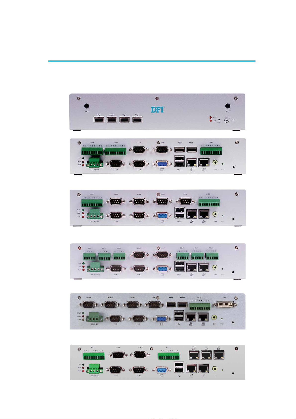
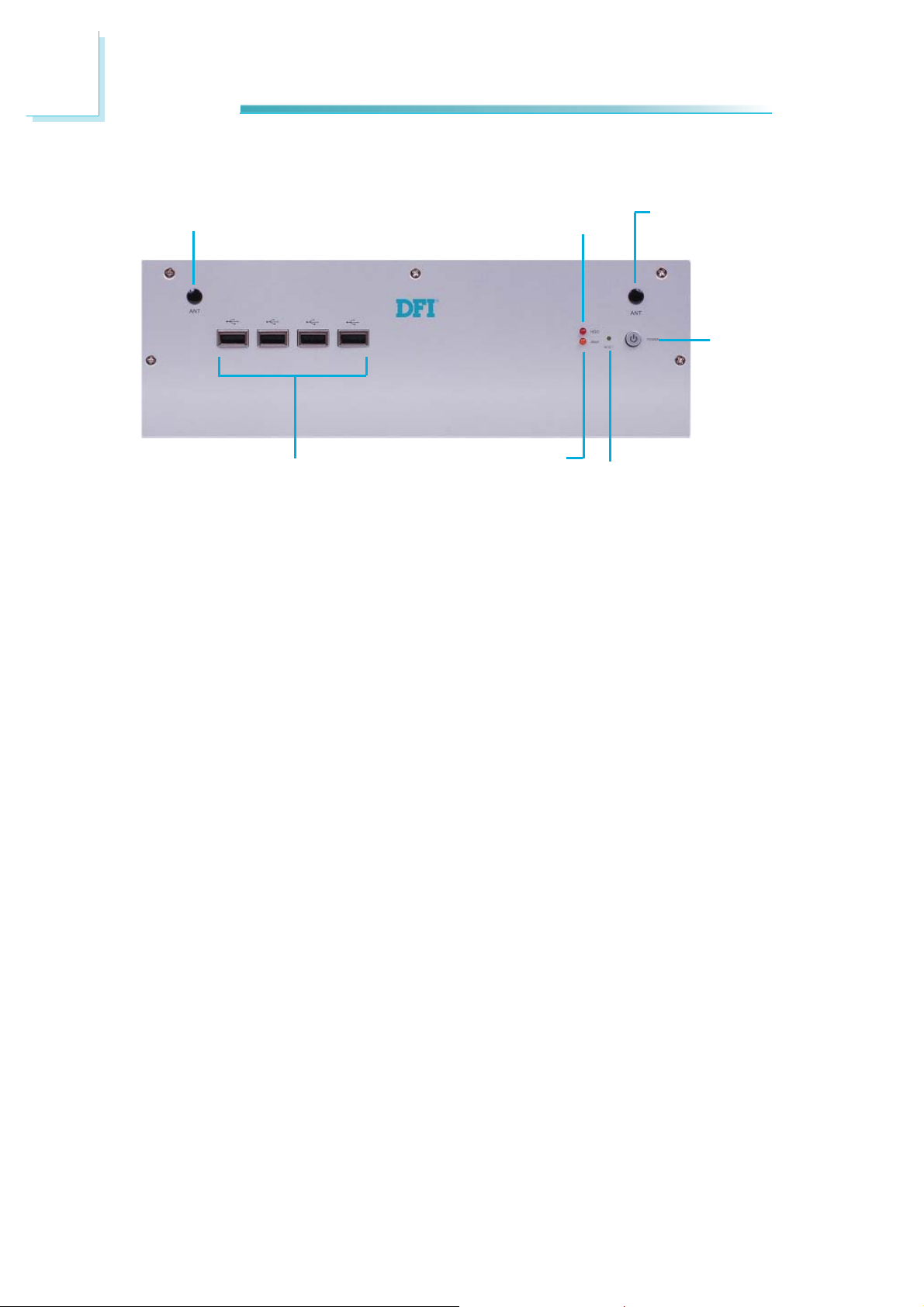
Getting to Know the EC200/210/220/221 Series
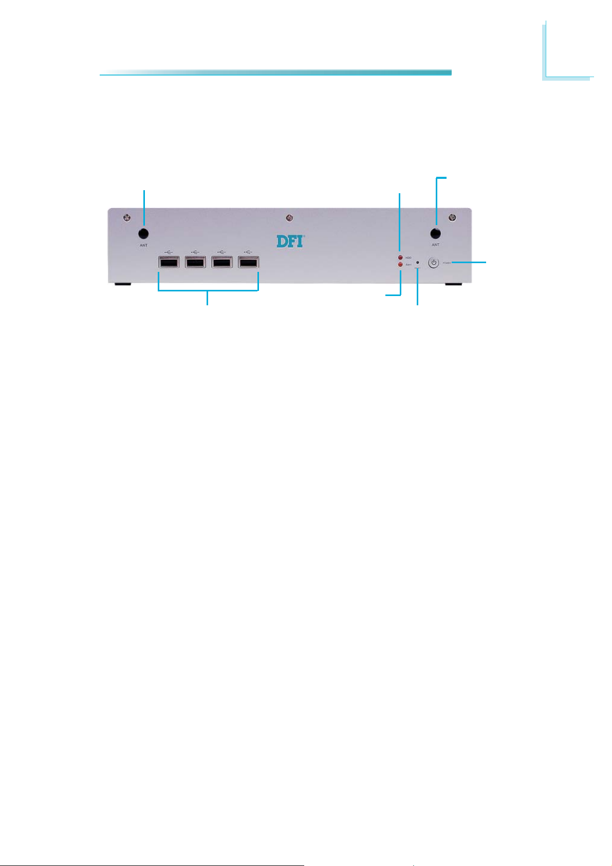
EC200 Series Front Panel
1
Wi-Fi MODULE
ANTENNA HOLE
ALERT LED
USB
Wi-Fi Module Antenna Hole
Used to connect to a Wi-Fi antenna.
USB Ports
Used to connect USB 2.0/1.1 devices.
HDD LED
Indicates the status of the hard drive.
Alert LED
Indicates the status when the CPU is over temperature.
HDD LED
Wi-Fi MODULE
ANTENNA HOLE
POWER
RESET
eset Switch
R
Press to reset the system.
Power Switch
Press to power-on or power-off the system.
19
Page 20
1
Introduction
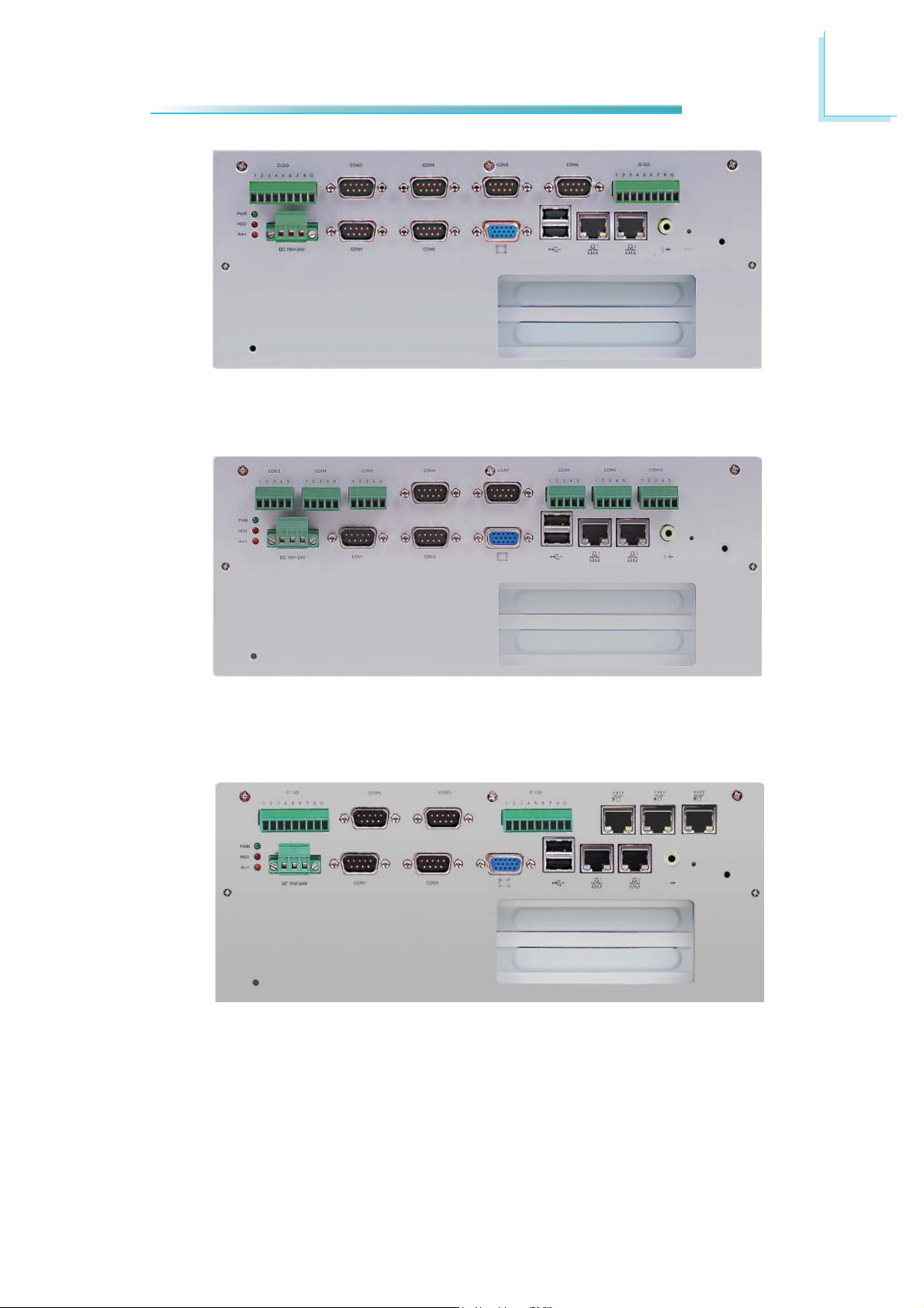
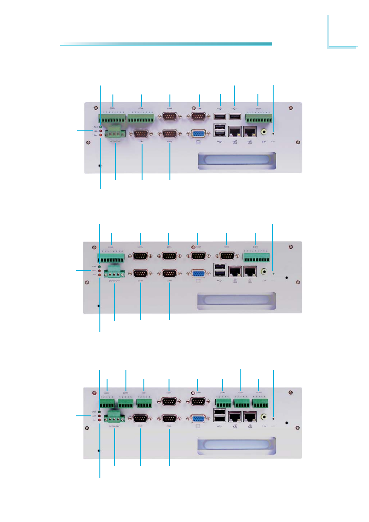
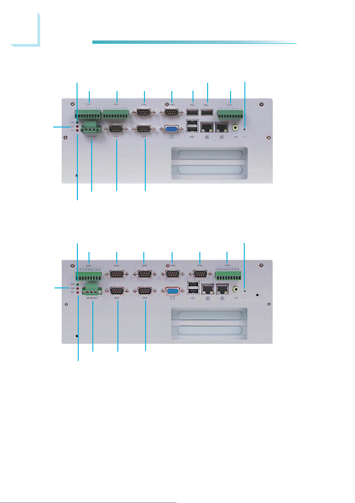
EC200 Series Rear Panel
HDD
HDD
POWER
COM3 COM4 COM5 COM6 USB
DC-IN
ALERT
COM1 COM2 VGA USB LAN LAN
EC200-LR6880
POWER
GPIO COM3 COM4 COM5
USB
COM6
RESET
GPIO
SPEAKER-OUT
RESET
GPIO
HDD
DC-IN
ALERT
POWER
COM3
DC-IN
ALERT
COM1 COM2 VGA USB LAN LAN
EC200-LR6G60
COM4
COM5 COM6
COM1 COM2 VGA USB LAN LAN
COM7 COM8
EC200-LRA060
SPEAKER-OUT
COM9
SPEAKER-OUT
RESET
COM10
20
Page 21
Introduction
1
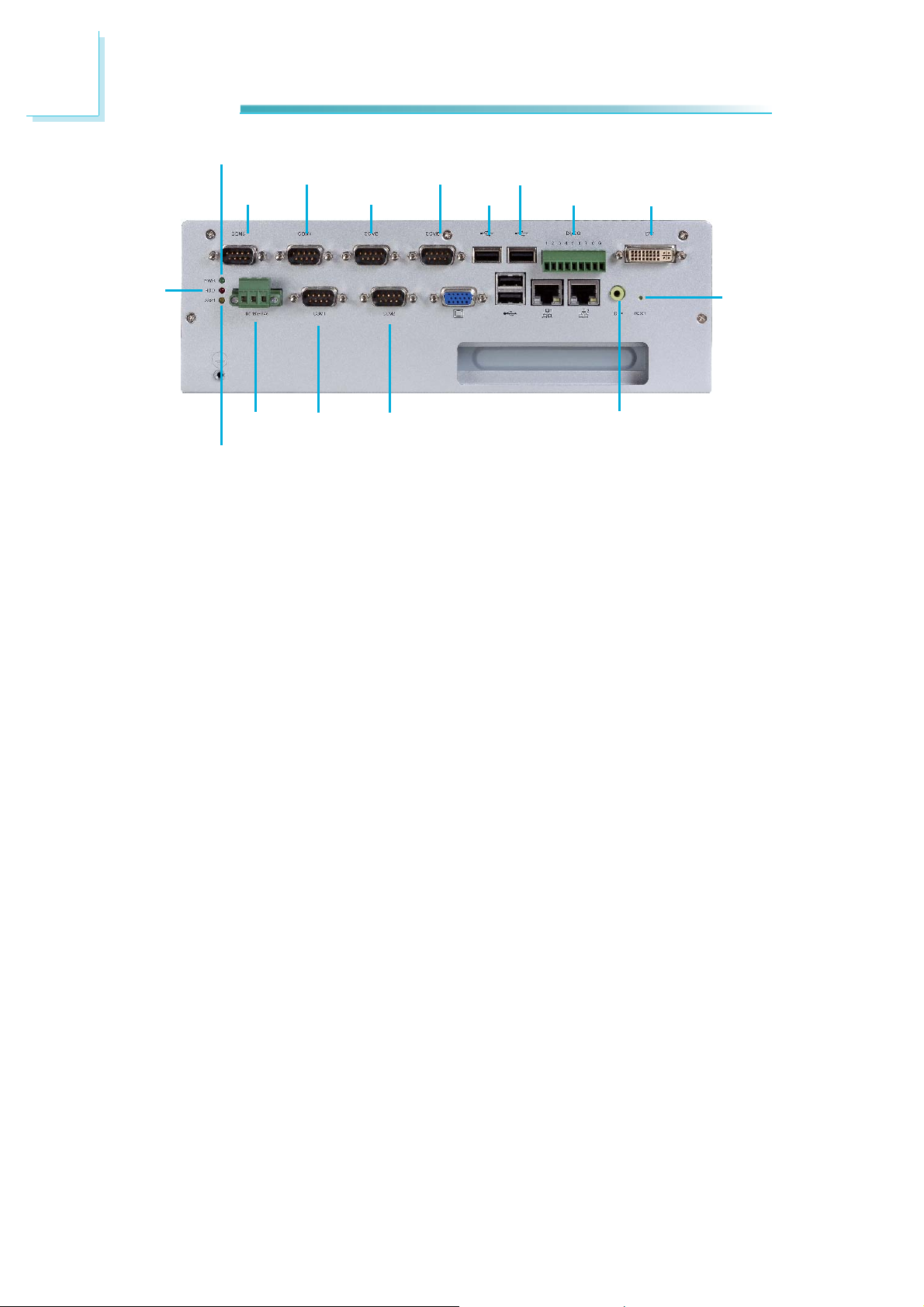
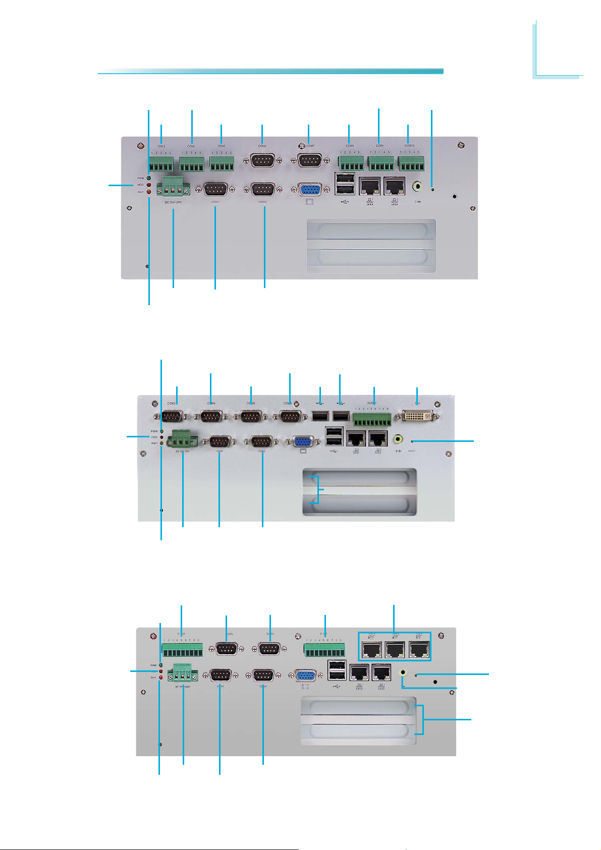
HDD
Power
HDD
COM4
COM3
DC-in COM1 COM2 VGA USB LAN LAN
Alert
COM5
COM6
USB
USB
EC200-LR6881
Power
GPIO COM3 COM4
DC-in
Alert
COM1 COM2 VGA USB LAN LAN
GPIO
EC200-LR4G65
GPIO
Reset
Speaker-out
LAN
Speaker-out
DVI
Reset
Power LED
Indicates the power status of the system.
HDD LED
Indicates the status of the hard drive.
Alert LED
Indicates the status when the CPU is over temperature.
DC
-in
Used to plug a DC power adapter.
COM P
Used to connect serial devices.
DVI Port
Used to connect a DVI device.
VGA Port
Used to connect an analog VGA monitor.
USB Ports
Used to connect USB 2.0/1.1 devices.
LAN Ports
Used to connect systems to a local area network.
orts
GPIO
Supports 8-bit digital output and input.
Speaker-out
Used to connect to a speaker.
Reset Switch
Press to reset the system.
21
Page 22
1
Introduction
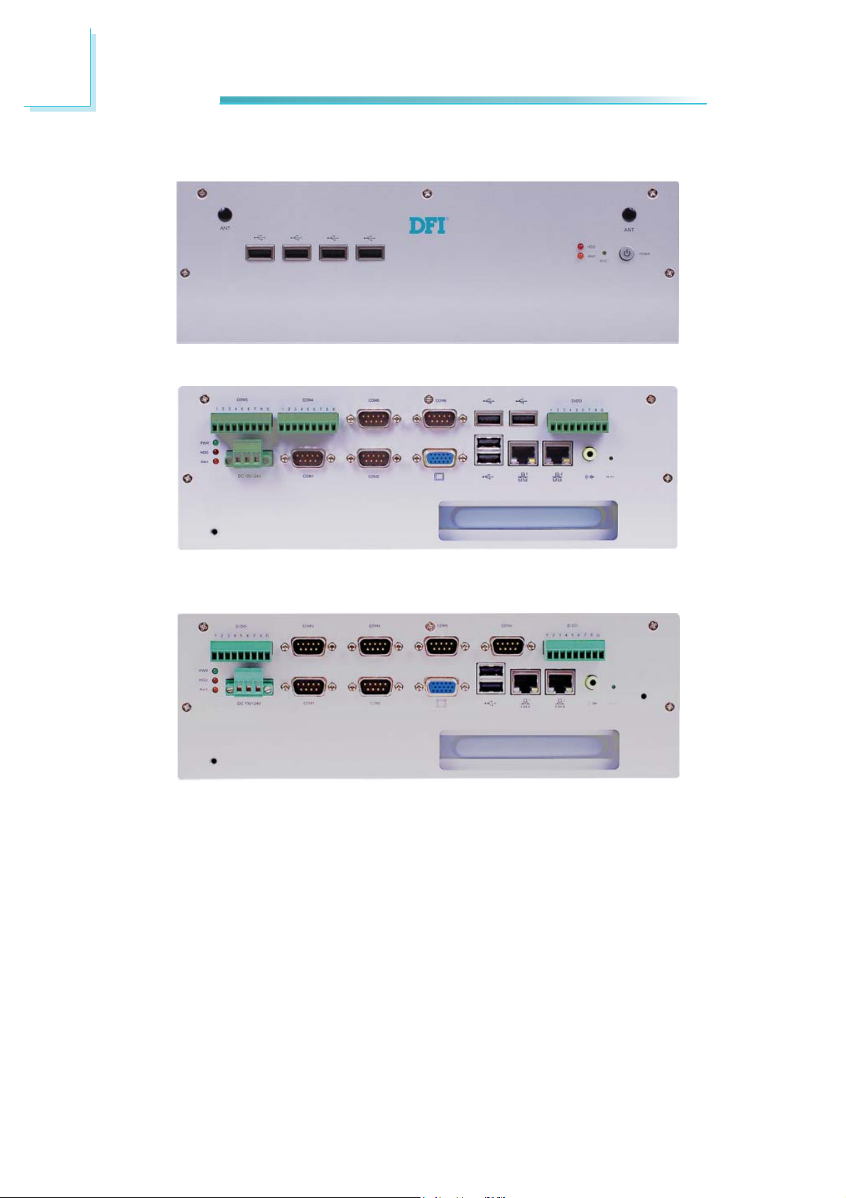
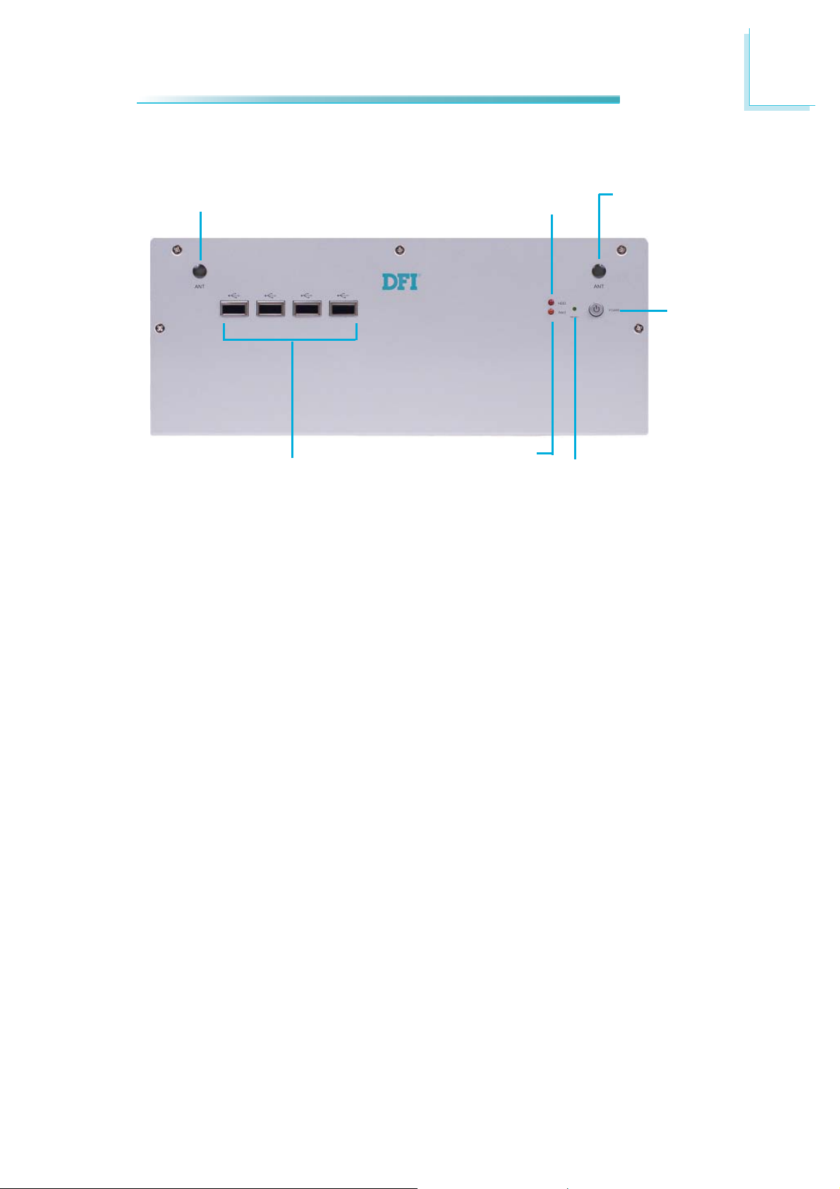
EC210 Series Front Panel
Wi-Fi MODULE
ANTENNA HOLE
USB
Wi-Fi Module Antenna Hole
Used to connect to a Wi-Fi antenna.
USB Ports
Used to connect USB 2.0/1.1 devices.
HDD LED
Indicates the status of the hard drive.
HDD LED
ALERT LED
Wi-Fi MODULE
ANTENNA HOLE
POWER
RESET
Alert LED
Indicates the status when the CPU is over temperature.
eset Switch
R
Press to reset the system.
Power Switch
Press to power-on or power-off the system.
22
Page 23
EC210 Series Rear Panel
1
Introduction
HDD
POWER
COM3 COM4 COM5 COM6
DC-IN
ALERT
POWER
GPIO COM3 COM4 COM5
COM1 COM2
USB
USB
VGA USB LAN LAN
PCI slot
EC210-LR6880
COM6
RESET
GPIO
SPEAKER-OUT
RESET
GPIO
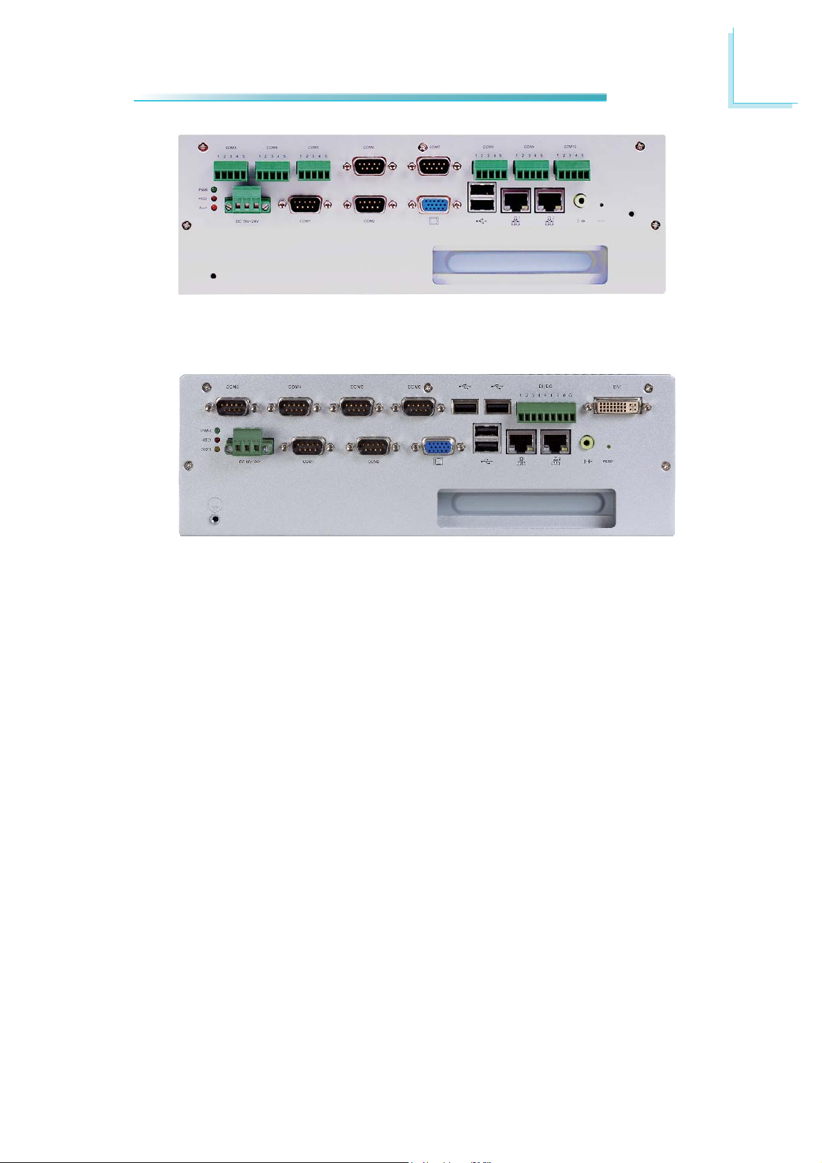
HDD
HDD
DC-IN
ALERT
POWER
COM3
COM1
COM4
COM5 COM6
COM2
VGA USB LAN LAN
PCI slot
EC210-LR6G60
COM7 COM8
VGA USB LAN LAN
PCI slot
COM9
SPEAKER-OUT
RESET
COM10
SPEAKER-OUT
DC-IN
ALERT
COM1 COM2
EC210-LRA060
23
Page 24
1
Introduction
Power
COM3
COM4
COM5
COM6
USB
USB
GPIO
DVI
HDD
VGA USB LAN LAN
PCI slot
DC-in
Alert
COM1 COM2
EC210-LR6881
Power LED
Indicates the power status of the system.
HDD LED
Indicates the status of the hard drive.
Alert LED
Indicates the status when the CPU is over temperature.
DC
-in
Used to plug a DC power adapter.
Reset
Speaker-out
COM Ports
Used to connect serial devices.
DVI Port
Used to connect a DVI device.
VGA Port
Used to connect an analog VGA monitor.
USB Ports
Used to connect USB 2.0/1.1 devices.
LAN Ports
Used to connect systems to a local area network.
GPIO
Supports 8-bit digital output and input.
Speaker-out
Used to connect to a speaker.
Reset Switch
Press to reset the system.
PCI slot
Supports to add on riser cards.
24
Page 25
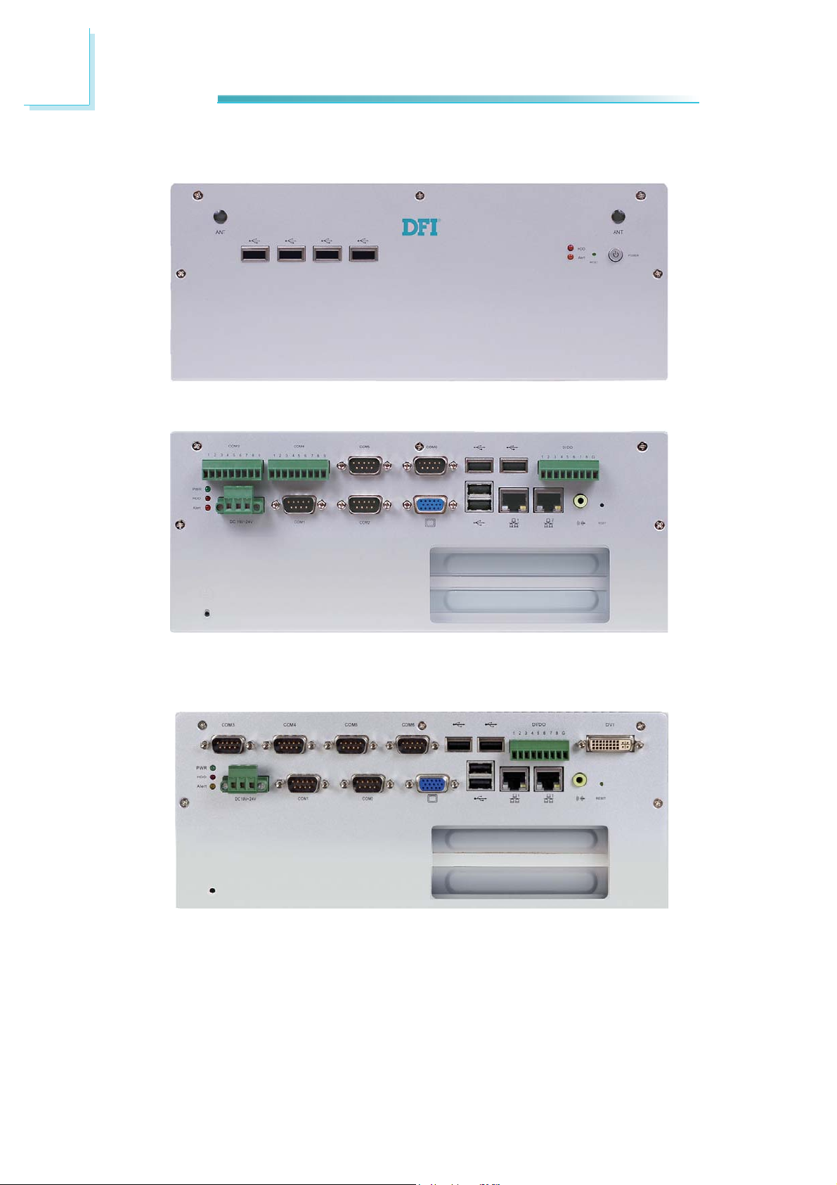
EC220/221 Series Front Panel
1
Introduction
Wi-Fi MODULE
ANTENNA HOLE
USB
Wi-Fi Module Antenna Hole
Used to connect to a Wi-Fi antenna.
USB Ports
Used to connect USB 2.0/1.1 devices.
HDD LED
ALERT LED
Wi-Fi MODULE
ANTENNA HOLE
POWER
RESET
HDD LED
Indicates the status of the hard drive.
Alert LED
Indicates the status when the CPU is over temperature.
eset Switch
R
Press to reset the system.
Power Switch
Press to power-on or power-off the system.
25
Page 26
1
Introduction
EC220/221 Series Rear Panel
HDD
POWER
COM3 COM4 COM5 COM6 USB
DC-IN
ALERT
COM1 COM2
EC220/221-LR6880
POWER
GPIO COM3 COM4 COM5
USB
GPIO
VGA USB LAN LAN
PCI / PCIe x1 slot
COM6
GPIO
RESET
SPEAKER-OUT
RESET
HDD
ALERT
DC-IN
COM1
SPEAKER-OUT
VGA USB LAN LAN
PCI / PCIe x1 slot
COM2
EC220/221-LR6G60
26
Page 27
Introduction
1
HDD
POWER
COM3
DC-IN
ALERT
Power
COM4
COM3
COM5 COM6
COM1 COM2
EC220/221-LRA060
COM4
COM5
COM7 COM8
VGA USB LAN LAN
PCI / PCIe x1 slot
COM6
USB
USB
COM9
GPIO
RESET
COM10
SPEAKER-OUT
DVI
HDD
HDD
Alert
Power
DC-in
GPIO
COM1 COM2
EC220/221-LR6881
COM3 COM4
VGA USB LAN LAN
PCI / PCIe x1 slot
GPIO
VGA USB LAN LAN
Speaker-out
Reset
LAN
Reset
Speaker-out
PCI slots
Alert
DC-in
COM1
COM2
EC220-LR4G65
27
Page 28

1
Introduction
Power LED
Indicates the power status of the system.
HDD LED
Indicates the status of the hard drive.
Alert LED
Indicates the status when the CPU is over temperature.
-in
DC
Used to plug a DC power adapter.
COM P
Used to connect serial devices.
DVI Port
Used to connect a DVI device.
VGA Port
Used to connect an analog VGA monitor.
USB Ports
Used to connect USB 2.0/1.1 devices.
LAN Ports
Used to connect systems to a local area network.
GPIO
Supports 8-bit digital output and input.
Speaker-out
Used to connect to a speaker.
Reset Switch
Press to reset the system.
orts
28
PCI/PCIe slot
Supports to add on riser cards.
Page 29
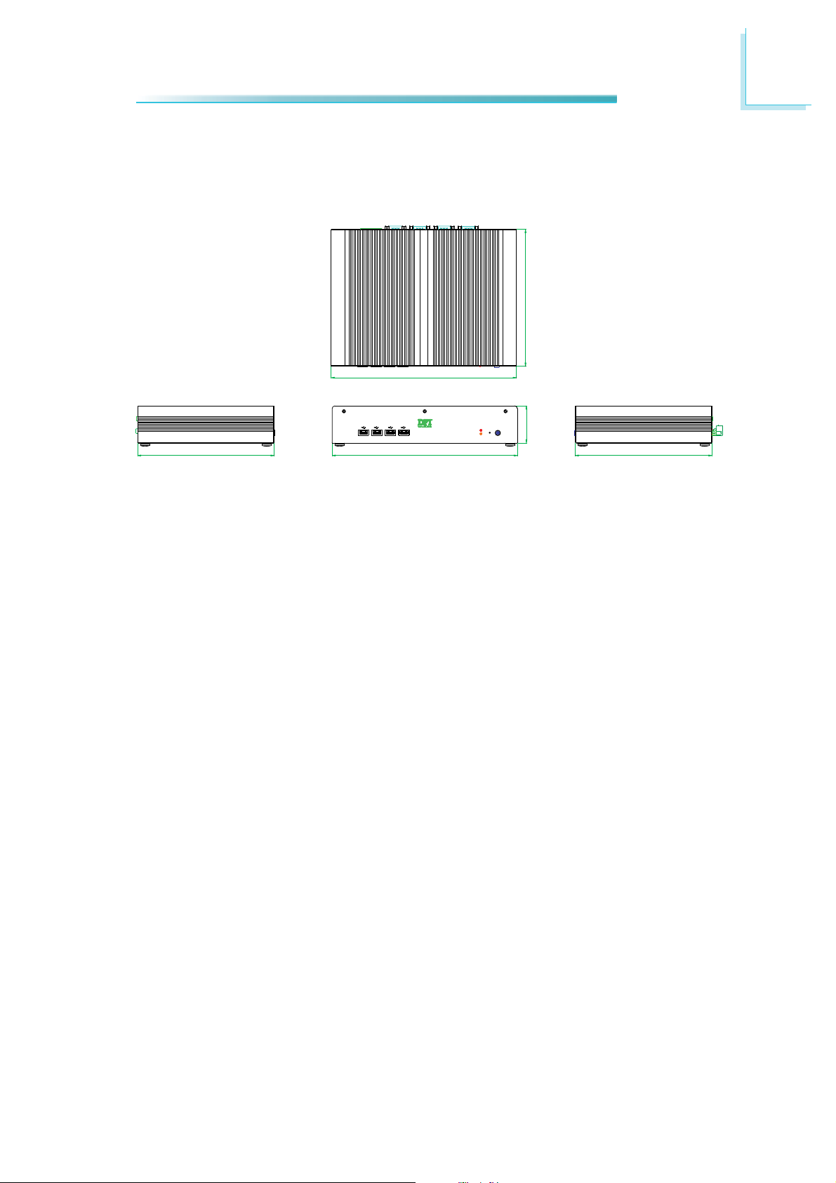
Mechanical Dimensions
EC200 Series
1
Introduction
203.00
275.00
R
203.00
Left View Front View Right View
275.00
POWER
55.00
203.00
29
Page 30
1
Introduction
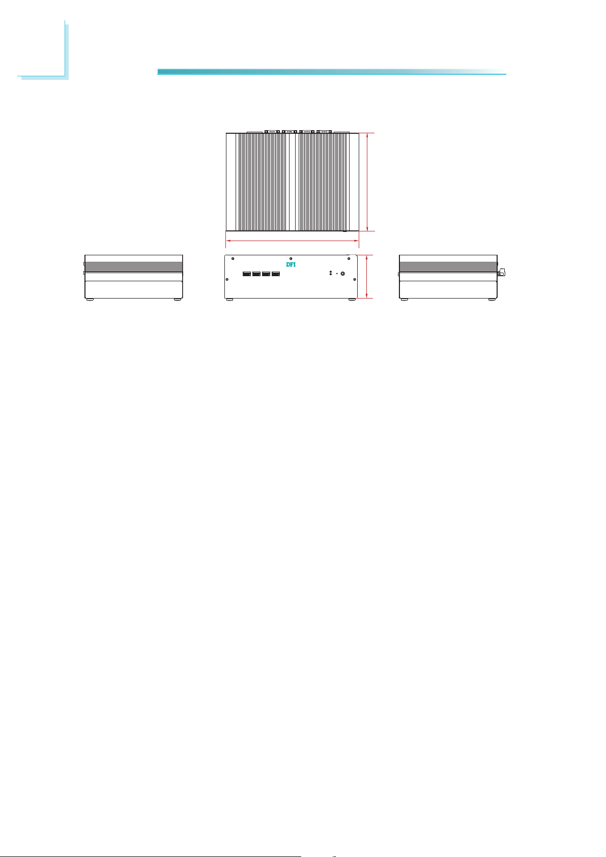
EC210 Series
211.00
275.00
90.00
Left View Front View Right View
30
Page 31

EC220/221 Series
211.00
275.00
110.00
Left View Front View Right View
1
Introduction
31
Page 32

2
Getting Started
Chapter 2 - Getting Started
Preparing the System
Before you start using the system, you need the following items:
• Memory module
• SATA hard drive
• DC power adapter
• USB keyboard
• USB mouse
• CD-ROM drive (for installing software/drivers)
• Screwdriver
Installing Devices
The following are devices that can be installed in the EC200/210/220/221 series
system.
• Memory module
• SATA hard drive
• CompactFlash card
• Mini PCIe card
• mSATA card
• PCI expansion card
• PCIe expansion card
Configuring the BIOS
To get you started, you may need to change configurations such as the date,
time and the type of hard disk drive.
1. Power-on the system.
2. After the memory test, the message “Press DEL to run setup” will appear on
the screen. Press the Delete key to enter the AMI BIOS setup utility.
Installing the Operating System
Most operating system software are provided in a CD therefore you need to install a CD-ROM drive in order to use the CD.
32
Make sure a 2.5” SATA drive is already installed.
1. Refer to the following chapters for information on connecting a CD-ROM drive
and installing a SATA drive.
2. Refer to your operating system manual for instructions on installing the operating system.
Page 33

Getting Started
Installing the Drivers
The system package includes a CD disk. The CD includes drivers that must be installed to provide the best system performance. Refer to the Supported Software
chapter for instructions on installing the drivers.
2
33
Page 34

3
Installing Devices
Chapter 3 - Installing Devices
Removing the Chassis Cover
1. Make sure the system and all other peripheral devices connected to it has
been powered-off.
2. Disconnect all power cords and cables.
3. The 10 mounting screws on the front and rear of the system are used to secure the cover to the chassis. Remove these screws and then put them in a
safe place for later use.
EC210/220/221
Mounting
screw
34
Page 35

Installing Devices
For EC200, you need to remove the 10 mounting screws on the front, rear and
bottom of the system.
EC200
Mounting
screw
3
35
Page 36

3
Installing Devices
4. After removing the mounting screws, lift the cover up.
Lift the Cover Upward
5. The SODIMM sockets and SATA drive bay are readily accessible after removing the chassis cover.
SODIMM sockets
SATA
drive bay
36
Page 37

Installing a SODIMM
1. Locate the SODIMM socket on the system board.
SODIMM sockets
3
Installing Devices
2. Note the key on the socket. The key ensures the module can be plugged into
the socket in only one direction.
37
Page 38

3
Installing Devices
3. Grasping the module by its edges, align the module into the socket at an approximately 30 degrees angle. Apply firm even pressure to each end of the
module until it slips down into the socket. The contact fingers on the edge of
the module will almost completely disappear inside the socket.
SODIMM
4. Push the module down until the clips at each end of the socket lock into
position. You will hear a distinctive “click”, indicating the module is correctly
locked into position.
ClipClip
38
Page 39

Installing Devices
Installing a SATA Drive
Standard model: 1 drive bay for 1 SATA drive
1. Align the mounting holes of the SATA drive with the mounting holes on the
HDD bracket and then use the provided mounting screws to secure the drive
in place.
SATA drive
HDD bracket
3
Mounting screw
39
Page 40

3
Installing Devices
2. Place the SATA drive (with HDD bracket) into the chassis. Align the mounting
holes on the HDD bracket with the mounting holes on the SATA drive bay and
then use the provided mounting screws to secure the drive in place.
Mounting hole
HDD bracket
Mounting hole
Mounting screw
40
Page 41

Installing Devices
3. Connect A to the SATA power/data connector on the SATA drive, B and C to
the SATA power connector and SATA data connector respectively on the system board.
B
3
SATA power/data
connector
C
A
SATA data
connector
SATA power
connector
41
Page 42

3
Installing Devices
Option model: 1 drive bay for 2 SATA drives
Note:
This model will be available upon request. Please contact your sales representative for more information.
SATA power/data
connector
SATA data
connector
SATA power
connector
42
SATA drive 2
SATA drive 1
Page 43

Installing Devices
Installing a CompactFlash Card
1. Turn the system to the bottom side. The 4 mounting screws on bottom of the
system are used to secure the cover to the chassis. Remove these screws
and then put them in a safe place for later use.
Mounting screw
3
2. After removing the cover, locate the CompactFlash socket. With the label
facing up, insert the CompactFlash card until it is completely seated in the
socket.
CompactFlash
CompactFlash
socket
card
43
Page 44

3
Installing Devices
Installing a Mini PCIe and/or mSATA Card
Latch
1. The latch is used to lock the Mini PCIe / mSATA card into position. Insert the
latch into the mounting holes and then push the latch down until the clips at
each end of the latch lock into position. You will hear a distinctive "click", indicating the latch is correctly locked into position.
Latch
Mini PCIe slot
Mounting hole
Latch
44
Page 45

Installing Devices
2. The system board is equipped with a Mini PCIe slot. The Mini PCIe slot supports full length or half length Mini PCIe / mSATA card. Note the key on the
slot. The key ensures the Mini PCIe / mSATA card can be plugged into the
slot in only one direction.
Half length
Full length
3
Removing the latch
If you want to move the latch in order to use the desired card, please follow below steps:
1. Remove the clips at each end of the latch once at a time.
2. Press the clips to the center of the latch and pull it up.
Pull up
Press to
the center
Latch
3. Pull the clips up and remove the latch.
45
Page 46

3
Installing Devices
Installing the Mini PCIe Card
1. Grasping the Mini PCIe card by its edges, align the card into the slot at an
approximately 30 degrees angle. Apply firm even pressure to each end of the
card until it slips down into the slot. The contact fingers on the edge of the
card will almost completely disappear inside the slot.
2. Push the Mini PCIe card down until the clips at each end of the latch lock
into position. You will hear a distinctive “click”, indicating the card is correctly
locked into position.
Clip
Clip
46
Page 47

Installing Devices
Installing the mSATA Card
1. Insert the latch into the mounting holes in accordance with the length of the
mSATA card. Push the latch down until the clips at each end of the latch lock
into position. You will hear a distinctive "click", indicating the latch is correctly locked into position.
Latch
3
2. Grasping the mSATA card by its edges, align the card into the slot at an approximately 30 degrees angle. Apply firm even pressure to each end of the
card until it slips down into the slot. The contact fingers on the edge of the
card will almost completely disappear inside the slot.
3. Push the mSATA card down until the clips at each end of the latch lock into
position. You will hear a distinctive “click”, indicating the card is correctly
locked into position.
Clip
Clip
47
Page 48

3
Installing Devices
Installing the PCI and PCIe Expansion Cards
Important:
When inserting the riser
card, please select a card
within 175mm (as shown
on the next picture) in order to fit in the slot.
1. The PCI and PCIe x1 slots on the riser card are used to install the expansion cards. To install the expansion cards, you need to remove the mounting
screws that secure the brackets to the chassis then remove the brackets.
Mounting screw
Bracket
PCIe x1 slot
48
PCI slot
Page 49

Installing Devices
2. To remove the mounting screws and the brackets, you need to remove the
hole plugs and insert the screwdriver thruogh the hole to access the mounting screws.
Bracket
Mounting screw
Hole plug
3
3. Remove these mounting screws and brackets, and then put them in a safe
place for later use.
49
Page 50

3
Installing Devices
4. Insert the Expansion card with a bracket into the PCI slot that is on the
riser card. Replace the screw you removed in step 3 to secure the bracket in
place.
Expansion card
Bracket
Mounting screw
5. Insert another Expansion card with a bracket into the PCIe slot that is on the
riser card. Replace the screw you removed in step 3 to secure the bracket in
place.
Expansion card
Bracket
Mounting screw
PCI
50
Front view
Note:
The Expansion cards used in the above illustrations may not resemble
the actual cards. These illustrations are for reference only.
Page 51

Installing Devices
Connecting Cables to Terminal Blocks
1. Insert one end of the power adaptor and the cable into the holes on the
power jack, and use the screwdriver tofasten the cables.
3
2. Connect the power jack to the connector on the system, and use the screwdriver to secure the power jack in place.
51
Page 52

3
Installing Devices
3. Insert one end of the cables into the holes on the terminal block, and use
the screwdriver to fasten the cables.
4. Connect the terminal block to the connector on the system, and use the
screwdriver to secure the terminal block in place.
52
Page 53

Chapter 4 - Jumper Settings
Jumper Settings - System Board
Clear CMOS Data
4
Jumper Settings
JP8
Normal (default)
VGA
Clear CMOS Data
If you encounter the following,
a) CMOS data becomes corrupted.
b) You forgot the supervisor or user password.
you can reconfi gure the system with the default values stored in the ROM BIOS.
312
1-2 On:
312
2-3 On:
To load the default values stored in the ROM BIOS, please follow the steps below.
1. Power-off the system and unplug the power cord.
2. Set JP8 pins 2 and 3 to On. Wait for a few seconds and set JP1 back to its
default setting, pins 1 and 2 On.
3. Now plug the power cord and power-on the system.
53
Page 54

4
Jumper Settings
PS/2 Power Select
VGA
312
1-2 On:
+5V (default)
JP2
+5V_standby
JP2 is used to select the power of the PS/2 keyboard/mouse port. Selecting
+5V_standby will allow you to use the PS/2 keyboard or PS/2 mouse to wake up
the system.
312
2-3 On:
54
Page 55

USB Power Select
4
Jumper Settings
312
1-2 On:
+5V (default)
312
2-3 On:
+5V_standby
JP4 and JP7 (for USB 0-3) are used to select the power of the USB ports. Selecting +5V_standby will allow you to use a USB device to wake up the system.
JP4
JP7
VGA
BIOS Setting
“USB Device Wakeup From S3/S4” in the Advanced menu (“ACPI Confi guration”
submenu) of the BIOS must be set to Enabled. Refer to chapter 7 for more information.
Important:
ou are using the Wake-On-USB Keyboard/Mouse function for 2 USB
If y
ports, the +5V_standby power source of your power supply must support ≥1.5A. For 3 or more USB ports, the +5V_standby power source of
your power supply must support ≥2A.
55
Page 56

4
Jumper Settings
CompactFlash Card Setting
VGA
Master (default)
JP9
JP9 is used to set the CompactFlash card to Master or Slave mode.
Note:
e do not recommend using IDE devices and CF card at the same time.
W
312
1-2 On:
312
2-3 On:
Slave
56
Page 57

COM1 and COM2 RS232/422/485 Select
4
Jumper Settings
2
1
JP11
6
5
JP5
VGA
JP11(COM1) and JP5(COM2) are used to confi gure COM1 and COM2 RS232,
RS422 (Full Duplex) or RS485 respectively.
64
2
531
1-2 On: RS232
(default)
DCD
TXD
RXD
DTR
GND
123 45
689
7
RI
CTS
RTS
DSR
JP11 JP5
64
2
531
3-4 On: RS422
Full Duplex
COM 1 / COM 2
RX+
TX+
RX-
TX-
GND
123 45
689
7
N.C.
N.C.
N.C.
N.C.
64
2
531
5-6 On: RS485
DATA+
N.C.
DATA-
N.C.
GND
123 45
689
7
N.C.
N.C.
N.C.
N.C.
57
Page 58

4
Jumper Settings
COM1 and COM2 RS232/Power Select
2
1
JP12
6
5
JP13
VGA
JP12(COM1) and JP13(COM2) are used to confi gure COM1 and COM2 to pure
RS232 or RS232 with power.
The pin function of COM1 and COM2 will vary according to JP12’s and JP13’s setting respectively.
58
64
2
531
1-3, 2-4 On:
RS232 (default)
DCD
TXD
RXD
DTR
123 4 5
689
7
CTS
RTS
DSR
JP12 / JP13
COM 1 / COM 2
GND
RI
64
2
531
3-5(+12V), 4-6(+5V) On:
RS232 with power
+5VTDRD
12345
6789
DTR-
GND
RTS-
CTS-
DSR-
+12V
Page 59

Power-on Select
4
Jumper Settings
VGA
JP6
312
1-2 On:
Power-on via
power button
(default)
312
2-3 On:
Power-on via
AC power
JP6 is used to select the method of powering on the system. If you want the
system to power-on whenever AC power comes in, set JP6 pins 2 and 3 to On. If
you want to use the power button, set pins 1 and 2 to On.
When using the JP6 “Power On” feature to power the system back on after a
power failure occurs, the system may not power on if the power lost is resumed
within 5 seconds (power fl icker).
Note:
In order to ensure that power is resumed after a power failure that re-
vers within a 5 second period, JP6 must be set to pins 2-3 and the
co
“PWRON After PWR-Fail” in CMOS is set to “On”.
59
Page 60

4
Jumper Settings
mPCIe/ mSATA Power Select
VGA
JP14
1
2
3
2-3 On:
3VDU
1
2
3
1-2 On:
3V3 (default)
JP14 is used to select the power supplied to the mPCIe and mSATA card that is on
the motherboard. Selecting 3V3 will be the default setting.
60
Page 61

mPCIe/ mSATA Select
JP1
Jumper Settings
12
10
4
VGA
2-3, 5-6, 8-9, 12-13 On:
JP1 is used to select MPCIe or mSATA. mPCIe is set as default.
31
1-2, 4-5, 7-8, 10-11 On:
mPCIe (default)
12
31
mSATA
10
61
Page 62

4
Jumper Settings
Jumper Settings - IO Board
EC200/210/220/221-LRA060
COM 3 to COM 10 RS232/RS422/RS485 Select
JP2 JP3 JP4 JP5 JP6 JP7 JP8
JP1
COM 3
(JP1)
COM 4
(JP2)
COM 5
(JP3)
COM 6
(JP4)
COM 7
(JP5)
COM 8
(JP6)
COM 9
(JP7)
COM 10
(JP8)
JP1 (for COM 3) to JP8 (for COM 10) are used to confi gure the COM ports to
RS232, RS422 (Full Duplex) or RS485.
The pin function of the COM ports will vary according to the jumper’s setting.
JP1 / JP2 / JP3 / JP4 / JP5 / JP6 / JP7 / JP8
64
2
531
1-2 On: RS232
(default)
RTS
TXD
CTS
RXD
12345
3-4 On: RS422
Full Duplex
COM 3 / COM 4 / COM 5 / COM 8 / COM 9 / COM 10
GND
RX+
12345
64
2
531531
TX+
RX-
TX-
GND
64
2
5-6 On: RS485
DATA+
N.C.
DATA-
N.C.
12345
GND
62
RS232
DCD
TXD
RXD
DTR
GND
123 45
689
7
RI
CTS
RTS
DSR
RS422
Full Duplex
COM 6 / COM 7
RX+
TX+
RX-
TX-
GND
123 4 5
689
7
N.C.
N.C.
N.C.
N.C.
RS485
DATA+
N.C.
DATA-
N.C.
GND
123 4 5
689
7
N.C.
N.C.
N.C.
N.C.
Page 63

COM 6 and COM 7 RS232/Power Select
4
Jumper Settings
JP9
COM 6
(JP9)
JP10
COM 7
(JP10)
JP9 and JP10 are used to confi gure COM 6 and COM 7 to pure RS232 or RS232
with power.
The pin function of COM 6 and COM 7 will vary according to JP9’s and JP10’s setting respectively.
JP9 / JP10
64
2
531
1-3, 2-4 On:
RS232 (default)
DCD
TXD
RXD
DTR
GND
123 45
689
7
CTS
RTS
DSR
COM 6 / COM 7
RI
64
2
531
3-5(+12V), 4-6(+5V) On:
RS232 with power
+5VTDRD
12345
6789
DTR-
GND
RTS-
CTS-
DSR-
+12V
63
Page 64

4
Jumper Settings
EC200/210/220/221-LR6880
COM 3 to COM 6 RS232/RS422/RS485 Select
JP1 JP2 JP5 JP8
COM 3
(JP1)
COM 4
(JP2)
COM 5
(JP5)
COM 6
(JP8)
JP1 (for COM 3), JP2 (for COM 4), JP5 (for COM 5) and JP8 (for COM6) are used
to confi gure the COM ports to RS232, RS422 (Full Duplex) or RS485.
The pin function of the COM ports will vary according to the jumper’s setting.
JP1 / JP2 / JP5 / JP8
64
2
1-2 On: RS232
(default)
TxD
DCD
3
1
5
531
GND
7
3-4 On: RS422
Full Duplex
COM 3 / COM 4
RTS
RI
9
1
Rx+
3
Tx+
64
2
531531
N.C.
5
GND
7
N.C.
9
2
5-6 On: RS485
N.C.
DATA+
3
1
5
64
GND
7
N.C.
N.C.
9
64
284
DTR
RxD
DCD
TXD
RXD
123 45
689
7
RTS
DSR
6
DTR
CTS
DSR
GND
RI
284
CTS
Rx-
COM 5 / COM 6
6
Tx-
N.C.
RX+
TX+
RX-
TX-
GND
123 45
689
7
N.C.
N.C.
N.C.
N.C.
N.C.
284
N.C.
DATA-
DATA+
N.C.
DATA-
123 4 5
689
7
N.C.
N.C.
6
N.C.
N.C.
N.C.
GND
N.C.
N.C.
Page 65

COM 3 to COM 6 RS232/Power Select
4
Jumper Settings
JP3
COM 3
(JP3)
JP6
COM 4
(JP6)
JP4
COM 5
(JP4)
JP7
COM 6
(JP7)
JP3, JP4, JP6 and JP7 are used to confi gure COM 3 to COM 6 to pure RS232 or
RS232 with power.
The pin function of COM 3 to COM 6 will vary according to JP3’s, JP4’s, JP6’s and
JP7’s setting respectively.
2
1-3, 2-4 On:
RS232 (default)
TxD
DCD
3
1
284
5
DTR
RxD
DCD
RXD
123 4 5
JP3 / JP4 / JP6 / JP7
64
531
COM 3 / COM 4
RTS
GND
6
TXD
DTR
7
DSR
RI
9
CTS
COM 5 / COM 6
GND
64
2
531
3-5(+12V), 4-6(+5V) On:
RS232 with power
TD
+5V
3
1
284
RD
12345
5
+5VTDRD
DTR-
GND
7
6
DTR-
RTS-
DSR-
GND
+12V
9
CTS-
689
7
RI
CTS
RTS
DSR
6789
RTS-
CTS-
DSR-
+12V
65
Page 66

4
Jumper Settings
Digital I/O Signal Voltage Select
JP9
DIO
JP9 is used to confi gure DIO to signal voltage select.
The pin function of DIO port will vary according to the jumper’s setting respectively.
1
2
3
1-2 On:
+3.3V (default)
1
DIO1
3
284
DIO2
JP9
DIO
DIO3
5
DIO4
DIO5
7
6
DIO6
DIO7
9
DIO8
1
2
3
2-3 On:
+5V
GND
66
Page 67

USB Power Select
4
Jumper Settings
JP10
USB0
JP10 (for USB 0-1) is used to select the power of the USB ports. Selecting +5V_
standby will allow you to use a USB device to wake up the system.
USB1
BIOS Setting
“USB Device Wakeup From S3/S4” in the Advanced menu (“ACPI Confi guration”
submenu) of the BIOS must be set to Enabled. Refer to chapter 7 for more information.
Important:
ou are using the Wake-On-USB Keyboard/Mouse function for 2 USB
If y
ports, the +5V_standby power source of your power supply must support ≥1.5A. For 3 or more USB ports, the +5V_standby power source of
your power supply must support ≥2A.
JP10
1
2
3
1
2
3
1-2 On:
+5V (default)
2-3 On:
+5V_standby
67
Page 68

4
Jumper Settings
EC200/210/220/221-LR6G60
COM 3 to COM 6 RS232/RS422/RS485 Select
JP1 JP2 JP5
COM 3
(JP1)
COM 4
(JP2)
COM 5
(JP5)
JP8
COM 6
(JP8)
JP1 (for COM 3), JP2 (for COM 4), JP5 (for COM 5) and JP8 (for COM 6) are used
to confi gure the COM ports to RS232, RS422 (Full Duplex) or RS485.
The pin function of the COM ports will vary according to the jumper’s setting.
JP1 / JP2 / JP5 / JP8
64
2
64
2
64
2
531
1-2 On: RS232
(default)
DCD
TXD
RXD
DTR
GND
123 45
689
7
RI
CTS
RTS
DSR
531531
3-4 On: RS422
Full Duplex
COM 3 / COM 4 / COM 5 / COM 6
RX+
TX+
RX-
TX-
GND
123 45
689
7
N.C.
N.C.
N.C.
N.C.
5-6 On: RS485
DATA+
N.C.
DATA-
N.C.
GND
123 45
689
7
N.C.
N.C.
N.C.
N.C.
68
Page 69

COM 3 to COM 6 RS232/Power Select
4
Jumper Settings
COM 3
(JP3)
JP6JP3
COM 4
(JP6)
JP4
COM 5
(JP4)
JP7
COM 6
(JP87)
JP3, JP4, JP6 and JP7 are used to confi gure COM 3 to COM 6 to pure RS232 or
RS232 with power.
The pin function of COM 3 to COM 6 will vary according to JP3’s, JP4’s, JP6’s and
JP7’s setting respectively.
64
2
531
1-3, 2-4 On:
RS232 (default)
COM 3 / COM 4 / COM 6 / COM 7
DCD
TXD
RXD
DTR
GND
123 4 5
689
7
CTS
RTS
DSR
JP3 / JP4 / JP6 / JP7
3-5(+12V), 4-6(+5V) On:
RS232 with power
RI
64
2
531
+5VTDRD
12345
6789
DTR-
RTS-
CTS-
DSR-
GND
+12V
69
Page 70

4
Jumper Settings
Digital I/O Signal Voltage Select
JP9
DIO1
JP9 is used to confi gure DIO to signal voltage select.
The pin function of DIO port will vary according to the jumper’s setting respectively.
JP9
132
1-2 On:
+3.3V (default)
1
DIO1 / DIO2
DIO3
DIO1
3
5
DIO5
7
DIO7
9
2-3 On:
GND
132
+5V
DIO2
70
284
DIO2
6
DIO4
DIO6
DIO8
Page 71

EC200/210/220/221-LR6881
COM 3 to COM 6 RS232/RS422/RS485 Select
4
Jumper Settings
COM 3
(JP1)
JP1
JP2 JP5
COM 4
(JP2)
COM 5
(JP5)
JP8
COM 6
(JP8)
JP1 (for COM 3), JP2 (for COM 4), JP5 (for COM 5) and JP8 (for COM 6) are used
to confi gure the COM ports to RS232, RS422 (Full Duplex) or RS485.
The pin function of the COM ports will vary according to the jumper’s setting.
JP1 / JP2 / JP5 / JP8
64
2
64
2
64
2
531
1-2 On: RS232
(default)
DCD
TXD
RXD
DTR
GND
123 45
689
7
RI
CTS
RTS
DSR
531531
3-4 On: RS422
Full Duplex
COM 3 / COM 4 / COM 5 / COM 6
RX+
TX+
RX-
TX-
GND
123 4 5
689
7
N.C.
N.C.
N.C.
N.C.
5-6 On: RS485
DATA+
N.C.
DATA-
N.C.
GND
123 45
689
7
N.C.
N.C.
N.C.
N.C.
71
Page 72

4
Jumper Settings
COM 3 to COM 6 RS232/Power Select
JP3
COM 3
(JP3)
JP6 JP4
COM 4
(JP6)
COM 5
(JP4)
JP7
COM 6
(JP7)
JP3, JP4, JP6 and JP7 are used to confi gure COM 3 to COM 6 to pure RS232 or
RS232 with power.
The pin function of COM 3 to COM 6 will vary according to JP3’s, JP4’s, JP6’s and
JP7’s setting respectively.
JP3 / JP4 / JP6 / JP7
64
2
531
1-3, 2-4 On:
RS232 (default)
COM 3 / COM 4 / COM 5 / COM 6
DCD
TXD
RXD
DTR
GND
123 4 5
689
7
CTS
RTS
DSR
RI
64
2
531
3-5(+12V), 4-6(+5V) On:
RS232 with power
+5VTDRD
12345
6789
DTR-
GND
RTS-
CTS-
DSR-
+12V
72
Page 73

Jumper Settings
Digital I/O Signal Voltage Select
JP9
DIO
JP9 is used to confi gure DIO to signal voltage select.
The pin function of DIO port will vary according to the jumper’s setting respectively.
4
1
2
3
1-2 On:
+3.3V (default)
1
DIO1
3
2
DIO2
JP9
DIO
DIO3
5
4
DIO4
DIO5
7
6
DIO6
DIO7
9
8
DIO8
1
2
3
2-3 On:
+5V
GND
73
Page 74

4
Jumper Settings
EC200/210/220/221-LR4G65
COM 3 and COM 4 RS232/RS422/RS485 Select
JP3
COM 4
(JP3)
JP1
COM 3
(JP1)
JP1 (for COM 3) and JP3 (for COM 4) are used to confi gure the COM ports to
RS232, RS422 (Full Duplex) or RS485.
The pin function of the COM ports will vary according to the jumper’s setting.
JP1 / JP3
64
2
64
2
64
2
531
1-2 On: RS232
(default)
DCD
TXD
RXD
DTR
GND
123 4 5
689
7
RI
CTS
RTS
DSR
531531
3-4 On: RS422
Full Duplex
COM 3 / COM 4
RX+
TX+
RX-
TX-
GND
123 4 5
689
7
N.C.
N.C.
N.C.
N.C.
5-6 On: RS485
DATA+
N.C.
DATA-
N.C.
GND
123 4 5
689
7
N.C.
N.C.
N.C.
N.C.
74
Page 75

COM 3 and COM 4 RS232/Power Select
4
Jumper Settings
JP4
COM 4
(JP4)
JP2
COM 3
(JP2)
JP2 and JP4 are used to confi gure COM 3 and COM 4 to pure RS232 or RS232
with power.
The pin function of COM 3 and COM 4 will vary according to JP2’s and JP4’s setting respectively.
64
2
531
1-3, 2-4 On:
RS232 (default)
DCD
TXD
RXD
DTR
GND
123 45
689
7
CTS
RTS
DSR
JP2 / JP4
3-5(+12V), 4-6(+5V) On:
COM 3 / COM 4
RI
64
2
531
RS232 with power
+5VTDRD
12345
DTR-
6789
RTS-
CTS-
DSR-
GND
+12V
75
Page 76

4
Jumper Settings
Digital I/O Signal Voltage Select
JP9
DIO1
JP9 is used to confi gure DIO to signal voltage select.
The pin function of DIO port will vary according to the jumper’s setting respectively.
JP9
132
1-2 On:
+3.3V (default)
DIO1 / DIO2
DIO3
1
DIO1
3
DIO5
5
7
DIO2
DIO7
9
132
2-3 On:
+5V
GND
76
2
4
DIO2
DIO4
6
8
DIO6
DIO8
Page 77

Chapter 5 - Ports and Connectors
Front Panel I/O Ports
For EC200/210/220/221
HDD LED
ALERT LED
USB
Ports and Connectors
5
POWER
RESET
The front panel I/O ports consist of the following:
• 1 HDD LED
• 1 Alert LED
• 1 Power Switch
• 1 Reset Switch
• 4 USB ports
77
Page 78

5
Ports and Connectors
USB Ports
USB allows data exchange between your computer and a wide range of simultaneously accessible external Plug and Play peripherals.
The system board is equipped with 4 USB 2.0/1.1 ports.
BIOS Setting
Confi gure the onboard USB in the Advanced menu (“USB Confi guration” sub-
menu) of the BIOS. Refer to chapter 7 for more information.
78
Page 79

Ports and Connectors
Wake-On-USB Keyboard/Mouse
The Wake-On-USB Keyboard/Mouse function allows you to use a USB keyboard or
USB mouse to wake up a system from the S3/S4 (STR - Suspend To RAM) state.
To use this function:
• Jumper Setting
JP6 must be set to “2-3 On: +5V_standby”. Refer to “USB Power Select” in
chapter 4 for more information.
• BIOS Setting
5
“USB Device Wakeup From S3/S4” in the Advanced menu (“ACPI Confi gur
tion” submenu) of the BIOS must be set to Enabled. Refer to chapter 7 for
more information.
Important:
ou are using the Wake-On-USB Keyboard/Mouse function for 2 USB
If y
ports, the +5V_standby power source of your power supply must support ≥1.5A. For 3 or more USB ports, the +5V_standby power source of
your power supply must support ≥2A.
a-
79
Page 80

5
Ports and Connectors
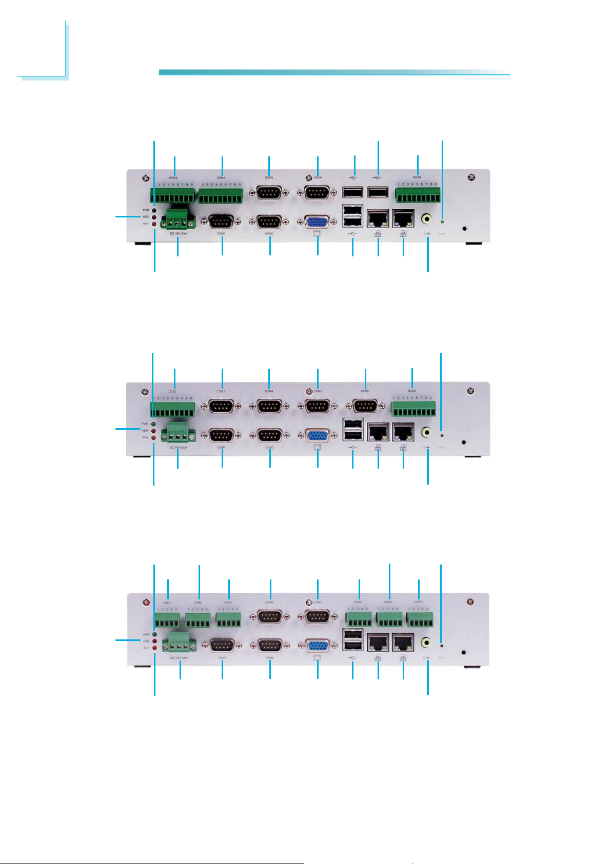
Rear Panel I/O Ports
For EC200
HDD
POWER
COM3 COM4 COM5 COM6 USB
DC-IN
ALERT
POWER
GPIO COM3 COM4 COM5
COM1 COM2 VGA USB LAN LAN
EC200-LR6880
USB
COM6
RESET
GPIO
SPEAKER-OUT
RESET
GPIO
HDD
HDD
DC-IN
ALERT
POWER
COM3
DC-IN
ALERT
COM1 COM2 VGA USB LAN LAN
EC200-LR6G60
COM4
COM5 COM6
COM1 COM2 VGA USB LAN LAN
COM7
COM8
SPEAKER-OUT
COM9
SPEAKER-OUT
RESET
COM10
80
EC200-LRA060
Page 81

Ports and Connectors
5
HDD
Power
COM3
Alert
Power
COM4
COM5
DC-in COM1 COM2 VGA USB LAN LAN
GPIO COM3 COM4
COM6
USB
EC200-LR6881
GPIO
USB
GPIO
Speaker-out
LAN
DVI
Reset
HDD
Alert
DC-in
COM1 COM2 VGA USB LAN LAN
Speaker-out
EC200-LR4G65
Reset
81
Page 82

5
Ports and Connectors
The rear panel I/O ports consist of the following:
EC200 - LR6880
• 1 Power LED
• 1 HDD LED
• 1 Alert LED
• Reset Switch
• DC-in power jack: 3-pole terminal block
• Speaker-out
• 1 VGA port
• 2 LAN ports
• 4 USB ports
• 4 DB-9 COM ports
• 2 9-pole COM ports
• 1 GPIO port
EC200 - LR6G60
• 1 Power LED
• 1 HDD LED
• 1 Alert LED
• Reset Switch
• DC-in power jack: 3-pole terminal block
• Speaker-out
• 1 VGA port
• 2 LAN ports
• 2 USB ports
• 2 GPIO ports
• 6 DB-9 COM ports
EC200 - LRA060
• 1 Power LED
• 1 HDD LED
• 1 Alert LED
• Reset Switch
• DC-in power jack: 3-pole terminal block
• Speaker-out
• 1 VGA port
• 2 LAN ports
• 2 USB ports
• 4 DB-9 COM ports
• 6 5-pole COM ports
82
Page 83

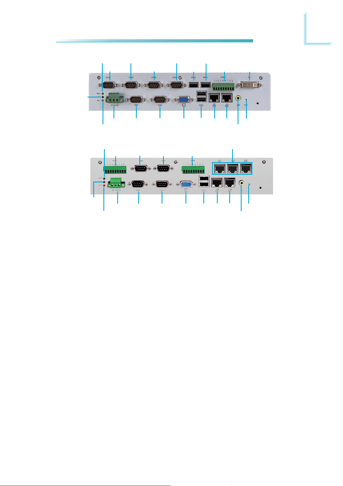
EC200 - LR6881
• 1 Power LED
• 1 HDD LED
• 1 Alert LED
• Reset Switch
• DC-in power jack: 3-pole terminal block
• Speaker-out
• 1 DVI port
• 1 VGA port
• 2 LAN ports
• 4 USB ports
• 6 DB-9 COM ports
• 1 GPIO port
EC200 - LR4G65
• 1 Power LED
• 1 HDD LED
• 1 Alert LED
• Reset Switch
• DC-in power jack: 3-pole terminal block
• Speaker-out
• 1 VGA port
• 5 LAN ports
• 2 USB ports
• 4 DB-9 COM ports
• 2 GPIO port
Ports and Connectors
5
83
Page 84

5
Ports and Connectors
For EC210
HDD
POWER
COM3 COM4 COM5 COM6
DC-IN
ALERT
POWER
GPIO COM3 COM4 COM5
COM1 COM2
EC210-LR6880
USB
USB
VGA USB LAN LAN
PCI slot
COM6
GPIO
GPIO
RESET
SPEAKER-OUT
RESET
HDD
HDD
DC-IN
ALERT
POWER
COM3
COM1
COM4
COM5 COM6
VGA USB LAN LAN
COM2
EC210-LR6G60
COM7
VGA USB LAN LAN
PCI slot
COM8
COM9
SPEAKER-OUT
RESET
COM10
84
ALERT
DC-IN
COM1 COM2
EC210-LRA060
PCI slot
SPEAKER-OUT
Page 85

The rear panel I/O ports consist of the following:
EC210 - LR6880
• 1 Power LED
• 1 HDD LED
• 1 Alert LED
• Reset Switch
• DC-in power jack: 3-pole terminal block
• Speaker-out
• 1 VGA port
• 2 LAN ports
• 4 USB ports
• 4 DB-9 COM ports
• 2 9-pole COM ports
• 1 GPIO port
EC210 - LR6G60
• 1 Power LED
• 1 HDD LED
• 1 Alert LED
• Reset Switch
• DC-in power jack: 3-pole terminal block
• Speaker-out
• 1 VGA port
• 2 LAN ports
• 2 USB ports
• 2 GPIO ports
• 6 DB-9 COM ports
Ports and Connectors
5
EC210 - LRA060
• 1 Power LED
• 1 HDD LED
• 1 Alert LED
• Reset Switch
• DC-in power jack: 3-pole terminal block
• Speaker-out
• 1 VGA port
• 2 LAN ports
• 2 USB ports
• 4 DB-9 COM ports
• 6 5-pole COM ports
85
Page 86

5
Ports and Connectors
EC210 - LR6881
• 1 Power LED
• 1 HDD LED
• 1 Alert LED
• Reset Switch
• DC-in power jack: 3-pole terminal block
• Speaker-out
• 1 DVI port
• 1 VGA port
• 2 LAN ports
• 4 USB ports
• 6 DB-9 COM ports
• 1 GPIO port
86
Page 87

For EC220/221
Ports and Connectors
5
HDD
POWER
COM3 COM4 COM5 COM6 USB
DC-IN
ALERT
POWER
GPIO COM3 COM4 COM5
COM1 COM2
EC220/221-LR6880
USB
GPIO
VGA USB LAN LAN
COM6
GPIO
RESET
SPEAKER-OUT
PCI / PCIe x1
slot
RESET
HDD
ALERT
DC-IN
COM1
VGA USB LAN LAN
COM2
EC220/221-LR6G60
SPEAKER-OUT
PCI / PCIe x1
slot
87
Page 88

5
Ports and Connectors
HDD
POWER
COM3
DC-IN
ALERT
Power
COM4
COM3
COM5 COM6
COM1 COM2
EC220/221-LRA060
COM4
COM5
COM7
VGA USB LAN LAN
COM6
USB
COM8
USB
COM9
GPIO
RESET
COM10
SPEAKER-OUT
PCI / PCIe x1
slot
DVI
HDD
HDD
Alert
Power
DC-in
GPIO
COM1 COM2
EC220/221-LR6881
COM3 COM4
VGA USB LAN LAN
PCI / PCIe x1 slot
GPIO
VGA USB LAN LAN
Reset
Speaker-out
LAN
Reset
Speaker-out
PCI slots
88
Alert
DC-in
COM1
COM2
EC220-LR4G65
Page 89

The rear panel I/O ports consist of the following:
EC220/221 - LR6880
• 1 Power LED
• 1 HDD LED
• 1 Alert LED
• Reset Switch
• DC-in power jack: 3-pole terminal block
• Speaker-out
• 1 VGA port
• 2 LAN ports
• 4 USB ports
• 4 DB-9 COM ports
• 2 9-pole COM ports
• 2 PCI (for EC220) / 1 PCIe/PCIe (for EC221)
• 1 GPIO port
EC220/221 - LR6G60
Ports and Connectors
5
• 1 Power LED
• 1 HDD LED
• 1 Alert LED
• Reset Switch
• DC-in power jack: 3-pole terminal block
• Speaker-out
• 1 VGA port
• 2 LAN ports
• 2 USB ports
• 2 GPIO ports
• 6 DB-9 COM ports
• 2 PCI (for EC220) / 1 PCIe/PCIe (for EC221)
EC220/221 - LRA060
• 1 Power LED
• 1 HDD LED
• 1 Alert LED
• Reset Switch
• DC-in power jack: 3-pole terminal block
• Speaker-out
• 1 VGA port
• 2 LAN ports
• 2 USB ports
• 2 PCI (for EC220) / 1 PCIe/PCIe (for EC221)
• 4 DB-9 COM ports
• 6 5-pole COM ports
89
Page 90

5
Ports and Connectors
EC220/221 - LR6881
• 1 Power LED
• 1 HDD LED
• 1 Alert LED
• Reset Switch
• DC-in power jack: 3-pole terminal block
• Speaker-out
• 1 DVI port
• 1 VGA port
• 2 LAN ports
• 4 USB ports
• 6 DB-9 COM ports
• 1 GPIO port
EC200 - LR4G65
• 1 Power LED
• 1 HDD LED
• 1 Alert LED
• Reset Switch
• DC-in power jack: 3-pole terminal block
• Speaker-out
• 1 VGA port
• 5 LAN ports
• 2 USB ports
• 4 DB-9 COM ports
• 2 GPIO port
90
Page 91

Ports and Connectors
LAN Ports
The LAN port allows the system board to connect to a local area network by
means of a network hub.
BIOS Setting
Confi gure “Wake on LAN” in the Advanced menu (“SuperIO Confi guration” sub-
menu) of the BIOS. Refer to chapter 7 for more information.
5
Driver Installation
Install the LAN drivers. Refer to chapter 8 for more information.
91
Page 92

5
Ports and Connectors
VGA Port
The VGA port is used for connecting a VGA monitor. Connect the monitor’s 15-pin
D-shell cable connector to the VGA port. After you plug the monitor’s cable connector into the VGA port, gently tighten the cable screws to hold the connector
in place.
BIOS Setting
Confi gure the onboard VGA in the Advanced menu (“ACPI Settings” submenu) of
the BIOS. Refer to chapter 7 for more information.
Driver Installation
Install the graphics driver. Refer to chapter 8 for more information.
92
Page 93

Ports and Connectors
Digital Input/Output
The Digital I/O connector provides powering-on function to an external device
that is connected to this connector.
5
Pin
Digital Output/ Input
Pin Assignment
1 DIO1
2
3 DIO3
4 DIO4
5 DIO5
6 DIO6
7 DIO7
8 DIO8
9 GND
DIO2
93
Page 94

5
Ports and Connectors
COM 3 to COM 10 RS232/RS422/RS485 Select
EC200/210/220/221-LRA060
JP2 JP3 JP4 JP5 JP6 JP7 JP8
JP1
COM 3
(JP1)
COM 4
(JP2)
COM 5
(JP3)
COM 6
(JP4)
COM 7
(JP5)
COM 8
(JP6)
COM 9
(JP7)
COM 10
(JP8)
JP1 (for COM 3) to JP8 (for COM 10) are used to confi gure the COM ports to
RS232, RS422 (Full Duplex) or RS485.
The pin function of the COM ports will vary according to the jumper’s setting.
JP1 / JP2 / JP3 / JP4 / JP5 / JP6 / JP7 / JP8
64
2
531
1-2 On: RS232
(default)
RTS
TXD
CTS
RXD
12345
3-4 On: RS422
Full Duplex
COM 3 / COM 4 / COM 5 / COM 8 / COM 9 / COM 10
GND
RX+
12345
64
2
531531
TX+
RX-
TX-
GND
64
2
5-6 On: RS485
DATA+
N.C.
DATA-
N.C.
12345
GND
94
RS232
DCD
TXD
RXD
DTR
GND
123 45
689
7
RI
CTS
RTS
DSR
RS422
Full Duplex
COM 6 / COM 7
RX+
TX+
RX-
TX-
GND
123 45
689
7
N.C.
N.C.
N.C.
N.C.
RS485
DATA+
N.C.
DATA-
N.C.
GND
123 45
689
7
N.C.
N.C.
N.C.
N.C.
Page 95

COM 6 and COM 7 RS232/Power Select
Ports and Connectors
5
JP9
COM 6
(JP9)
JP10
COM 7
(JP10)
JP9 and JP10 are used to confi gure COM 6 and COM 7 to pure RS232 or RS232
with power.
The pin function of COM 6 and COM 7 will vary according to JP9’s and JP10’s setting respectively.
64
2
531
1-3, 2-4 On:
RS232 (default)
DCD
TXD
RXD
DTR
GND
123 4 5
689
7
CTS
RTS
DSR
JP9 / JP10
COM 6 / COM 7
RI
64
2
531
3-5(+12V), 4-6(+5V) On:
RS232 with power
+5VTDRD
12345
DTR-
6789
RTS-
CTS-
DSR-
GND
+12V
95
Page 96

5
Ports and Connectors
COM 3 to COM 6 RS232/RS422/RS485 Select
EC200/210/220/221-LR6880
JP1 JP2 JP5 JP8
COM 3
(JP1)
COM 4
(JP2)
COM 5
(JP5)
COM 6
(JP8)
JP1 (for COM 3), JP2 (for COM 4), JP5 (for COM 5) and JP8 (for COM6) are used
to confi gure the COM ports to RS232, RS422 (Full Duplex) or RS485.
The pin function of the COM ports will vary according to the jumper’s setting.
JP1 / JP2 / JP5 / JP8
64
2
1-2 On: RS232
(default)
TxD
DCD
3
1
5
531
GND
7
3-4 On: RS422
Full Duplex
COM 3 / COM 4
RTS
RI
9
1
Rx+
3
Tx+
64
2
531531
N.C.
5
GND
7
N.C.
9
2
5-6 On: RS485
N.C.
DATA+
3
1
5
64
GND
7
N.C.
N.C.
9
96
284
DTR
RxD
DCD
TXD
RXD
123 45
689
7
RTS
DSR
6
DTR
CTS
DSR
GND
RI
284
CTS
Rx-
COM 5 / COM 6
6
Tx-
N.C.
RX+
TX+
RX-
TX-
GND
123 45
689
7
N.C.
N.C.
N.C.
N.C.
N.C.
284
N.C.
DATA-
DATA+
N.C.
DATA-
123 4 5
689
7
N.C.
N.C.
6
N.C.
N.C.
N.C.
GND
N.C.
N.C.
Page 97

COM 3 to COM 6 RS232/Power Select
Ports and Connectors
5
JP3
COM 3
(JP3)
JP6
COM 4
(JP6)
JP4
COM 5
(JP4)
JP7
COM 6
(JP7)
JP3, JP4, JP6 and JP7 are used to confi gure COM 3 to COM 6 to to pure RS232
or RS232 with power.
The pin function of COM 3 to COM 6 will vary according to JP3’s, JP4’s, JP6’s and
JP7’s setting respectively.
2
1-3, 2-4 On:
RS232 (default)
TxD
DCD
3
1
284
5
DTR
RxD
DCD
RXD
123 45
JP3 / JP4 / JP6 / JP7
64
531
COM 3 / COM 4
RTS
GND
6
TXD
DTR
7
DSR
RI
9
CTS
COM 5 / COM 6
GND
64
2
531
3-5(+12V), 4-6(+5V) On:
RS232 with power
TD
+5V
3
1
284
RD
+5VTDRD
12345
5
DTR-
GND
7
6
DTR-
RTS-
DSR-
GND
+12V
9
CTS-
689
7
RI
CTS
RTS
DSR
6789
RTS-
CTS-
DSR-
+12V
97
Page 98

5
Ports and Connectors
COM 3 to COM 6 RS232/RS422/RS485 Select
EC200/210/220/221-LR6G60
JP1 JP2 JP5
COM 3
(JP1)
COM 4
(JP2)
COM 5
(JP5)
JP8
COM 6
(JP8)
JP1 (for COM 3), JP2 (for COM 4), JP5 (for COM 5) and JP8 (for COM 6) are used
to confi gure the COM ports to RS232, RS422 (Full Duplex) or RS485.
The pin function of the COM ports will vary according to the jumper’s setting.
JP1 / JP2 / JP5 / JP8
64
2
64
2
64
2
531
1-2 On: RS232
(default)
DCD
TXD
RXD
DTR
GND
123 45
689
7
RI
CTS
RTS
DSR
531531
3-4 On: RS422
Full Duplex
COM 3 / COM 4 / COM 5 / COM 6
RX+
TX+
RX-
TX-
GND
123 45
689
7
N.C.
N.C.
N.C.
N.C.
5-6 On: RS485
DATA+
N.C.
DATA-
N.C.
GND
123 45
689
7
N.C.
N.C.
N.C.
N.C.
98
Page 99

COM 3 to COM 6 RS232/Power Select
Ports and Connectors
5
COM 3
(JP3)
JP6JP3
COM 4
(JP6)
JP4
COM 5
(JP4)
JP7
COM 6
(JP87)
JP3, JP4, JP6 and JP7 are used to confi gure COM 3 to COM 6 to to pure RS232
or RS232 with power.
The pin function of COM 3 to COM 6 will vary according to JP3’s, JP4’s, JP6’s and
JP7’s setting respectively.
JP3 / JP4 / JP6 / JP7
64
2
531
1-3, 2-4 On:
RS232 (default)
COM 3 / COM 4 / COM 6 / COM 7
DCD
TXD
RXD
DTR
GND
123 4 5
689
7
CTS
RTS
DSR
RI
64
2
531
3-5(+12V), 4-6(+5V) On:
RS232 with power
+5VTDRD
12345
DTR-
6789
RTS-
CTS-
DSR-
GND
+12V
99
Page 100

5
Ports and Connectors
EC200/210/220/221-LR6881
COM 3 to COM 6 RS232/RS422/RS485 Select
JP1
COM 3
(JP1)
JP2 JP5
COM 4
(JP2)
COM 5
(JP5)
JP8
COM 6
(JP8)
JP1 (for COM 3), JP2 (for COM 4), JP5 (for COM 5) and JP8 (for COM 6) are used
to confi gure the COM ports to RS232, RS422 (Full Duplex) or RS485.
The pin function of the COM ports will vary according to the jumper’s setting.
JP1 / JP2 / JP5 / JP8
64
2
64
2
64
2
531
1-2 On: RS232
(default)
DCD
TXD
RXD
DTR
GND
123 45
689
7
RI
CTS
RTS
DSR
531531
3-4 On: RS422
Full Duplex
COM 3 / COM 4 / COM 5 / COM 6
RX+
TX+
RX-
TX-
GND
123 4 5
689
7
N.C.
N.C.
N.C.
N.C.
5-6 On: RS485
DATA+
N.C.
DATA-
N.C.
GND
123 45
689
7
N.C.
N.C.
N.C.
N.C.
100
 Loading...