

Page 1

EB3486-TN
Station Board
User's Manual
- D19431126 -
Page 2

v Copyright 1993, by DFI Inc.
All rights reserved.
No part of this document may be copied or reproduced
in any form or by any means without the prior written
consent of DFI, Inc.
DFI, Inc. makes no warranties with respect to this
documentation and disclaims any implied warranties of
merchantability, quality, or fitness for any particular
purpose. The information in this document is subject to
change without notice. DFI, Inc. reserves the right to
make revisions to this publication and to make changes
to any and/or all parts of its content, at any time,
without obligation to notify any person or entity of such
changes. Further, DFI, Inc. assumes no responsibility
for any errors that may appear in this document.
DFI is a registered trademark and EB3486-TN is a
trademark of Diamond Flower Inc. All other product
names mentioned are trademarks or registered trademarks of their respective companies.
Page 3

v FCC Statement on Class B
This equipment has been tested and found to comply
with the limits for a Class B digital device, pursuant to
Part 15 of the FCC Rules. These limits are designed to
provide reasonable protection against harmful interference when the equipment is operated in a residential
installation. This equipment generates, uses, and can
radiate radio frequency energy and if not installed and
used in accordance with the instruction manual may
cause harmful interference to radio communications.
However, there is no guarantee that interference will
not occur in a particular installation. If this equipment
does cause harmful interference to radio or television
reception, which can be determined by turning the
equipment off and on, the user is encouraged to try to
correct the interference by one or more of the following
measures:
• Reorient or relocate the receiving antenna.
• Increase the separation between the equipment and
receiver.
• Connect the equipment into an outlet on a circuit
different from that to which the receiver is con-
nected.
• Consult the dealer or an experienced radio TV
techni-
cian for help.
Notice:
(1) The changes or modifications not expressly ap-
proved
by the party responsible could void the user’s au-
thor-
ity to operate the equipment.
(2) Shielded interface cables must be used in order to
comply with the emission limits.
Page 4

v Table of Contents v
Introduction.......................................................................................
Features and Specifications .......................................................
Installation Overview ......................................................................
Preparing the Area .....................................................................
Handling the System Board .......................................................
Tips in Handling the System Board ....................................
Installing the System Board .......................................................
Hardware Installation ......................................................................
Memory Installation ....................................................................
Installing the Modules ..........................................................
Board Configuration ...................................................................
Jumper Settings ...................................................................
CPU Modules ....................................................................................
DBII-486SX/DX/DX2 CPU Modules ...........................................
DBII-486C Rev. 0 CPU Modules ...............................................
DBII-486C Rev. B CPU Modules ...............................................
Initial Setup Program ......................................................................
AMI BIOS Setup Utilities ............................................................
Standard CMOS Setup ...................................................
Advanced CMOS Setup ......................................................
Auto Configuration with BIOS Defaults ..............................
Auto Configuration with Power-on Defaults .......................
Change Password ...............................................................
Auto Detect Hard Disk ........................................................
Hard Disk Utility ...................................................................
Write to CMOS and Exit ......................................................
Do not write to CMOS and Exit ..........................................
1-1
1-2
2-1
2-1
2-2
2-2
2-3
3-1
3-1
3-5
3-6
3-7
4-1
4-2
4-4
4-8
5-1
5-2
5-3
5-5
5-8
5-9
5-9
5-11
5-11
5-12
5-13
Page 5

EISA Configuration Utility ............................................................
Overview ...................................................................................
File Structure .............................................................................
Initial Configuration ...................................................................
Main Menu .................................................................................
Step 1: About EISA Configuration......................................
Step 2: Add and Remove Boards......................................
Step 3: Change Configuration Settings.............................
Step 4: Save Configuration................................................
Step 5: View Switch/Jumper Settings................................
Step 6: Exit .........................................................................
Utilities Configuration..........................................................
Define ISA Board.................................................................
6-1
6-1
6-1
6-2
6-3
6-4
6-4
6-9
6-15
6-16
6-17
6-18
6-21
DEMM 386 Software Driver ...........................................................
Troubleshooting Checklist ...........................................................
Appendix A: Types of Modules .................................................
Appendix B: System Error Report ............................................
Appendix C: Memory & I/O Maps ..............................................
Appendix D: EISA I/O PIin Assignments...................................
Appenidx E: System Overview...................................................
Appendix F: Connector Pin Assignments ...............................
Appenidx G: AMI BIOS Hard Disk Table....................................
Appendix H: VESA VL-Bus Slot Pin Assignments..................
7-1
8-1
A-1
B-1
C-1
D-1
E-1
F-1
G-1
H-1
Page 6

Read Me First
The EB3486-TN system board requires the installation of the
ECU (EISA Configuration Utility), found on the provided EISA
Configuration Utility diskette, for proper operation of this
system board.
The ECU configures the EISA devices and maintains system
parameters by storing them in the Extended CMOS Memory, so
the BIOS can initialize the system and expansion boards
inserted in the EISA slots once you power up your system.
The Extended CMOS Memory is equipped with an internal
battery that needs to be constantly charged. In a small number
of cases, the internal battery may have drained and the
information stored in the Extended CMOS Memory lost during
shipment. If this happens, you will get the message "EISA
CMOS Inoperational" when you power up your system. Simply
run the ECU software, bundled with the system board, to
reconfigure the system. Save the configuration and reboot your
system. Refer to the EISA Configuration Utility section on
page 6-1 for more detailed information.
Page 7

v Introduction
The EB3486-TN is a revolutionary station board based
on our own Processor Upgradeable Microcomputer
Architecture (PUMA) platform. It's unique design
allows you to use either a 486SX, 486DX or 486DX2
CPU at any speed on the station board. This is accomplished by installing the CPU on a CPU module that
plugs directly into the station board, thus making it easy
and affordable to upgrade.
The EB3486-TN station board is equipped with one
VESA compliant local bus slot for use with local bus
video or network cards. Any future VESA local-bus
products will also work. In addition to the VESA local
bus slot, the station board also has eight 32-bit EISA
(Extended Industry Standard Architecture) expansion
slots and one CPU module slot.
EISA extends the operational capabilities of the ISA
(Industry Standard Architecture) standard while maintaining compatibility with ISA expansion boards. The
EISA Configuration Utility (ECU) must be installed and
run to configure the board and the EISA expansion
boards that will be inserted in the EISA expansion slots.
EB3486-TN
If you have a DBII-486CSX or DBII-486CDX/DX2
CPU module, the system will consist of two levels of
cache memory for fast local access of frequently accessed code and data. The first level, or internal cache,
is built-in to the CPU with 8KB of cache memory. The
second level, or external cache, can support 32KB/64KB
of cache memory using 8Kx8 (25ns) SRAMs or 128KB/
256KB of
cache memory using 32Kx8 (25ns) SRAMs. The
DBII-486SX or DBII-486DX/DX2 CPU modules only
Introduction u 1-1
Page 8

PUMA Station Board
support internal cache.
The EB3486-TN station board uses 256Kx36, 512Kx36,
1Mx36, 2Mx36, 4Mx36, 8Mx36, 16Mx36 and 32Mx36
SIM modules with speeds of 70ns or 80ns. It can hold
128MB of memory onboard configurable in 30 different
sizes.
System support functions include system BIOS and
VGA BIOS Shadow RAM support, memory remapping,
seven channels of Direct Memory Access, 14 levels of
interrupts and five programmable timers.
Features and Specifications
• CPU Modules : DBII and DBVII Series
DBII Series (without external cache)
DBII-486:
25/33MHz - 486SX (PGA, PQFP)
25/33MHz - 486DX (PGA)
50/66MHz - 486DX2 (PGA)
DBII Series (with external cache)
DBII-486C: (Rev. 0/Rev. B)
DBVII Series (with Local bus VGA)
DBVII-486:
1-2 u Introduction
25/33MHz - 486SX (PGA)
25/33MHz - 486DX (PGA)
50/66MHz - 486DX2 (PGA)
20/25/33MHz - 486SX (PGA, PQFP)
25/33MHz - 486DX (PGA)
Page 9

EB3486-TN
50/66MHz - 486DX2 (PGA)
Note:
Each type of 486 CPU Module, DBII-486SX/DX/DX2,
DBII-486CSX/DX/DX2 and DBVII-486SX/DX/DX2,
support all speeds of 486 CPU's. Jumpers on the CPU
module select between SX, DX, or DX2 CPU's.
PGA stands for Pin Grid Array.
PQFP stands for Plastic Quad Flatpack Package.
• Uses AMI BIOS: 27512-20 (1)
• Uses TI TACT84500 EISA chipset
• 8.25 MHz bus speed for 33/66MHz
8.33 MHz bus speed for 25/50MHz
• Uses 256Kx36, 512Kx36, 1Mx36, 2Mx36, 4Mx36,
8Mx36, 16Mx36 and 32Mx36 SIM modules
(70/80ns)
• Memory configurable up to 128MB
Memory configurable as 1MB, 2MB, 3MB, 4MB,
6MB, 8MB, 9MB, 10MB, 11MB, 12MB, 14MB,
16MB, 20MB, 24MB, 28MB, 32MB, 36MB, 40MB,
44MB, 48MB 56MB, 64MB, 68MB, 72MB, 80MB,
96MB, 100MB, 104MB, 112MB or 128MB.
• External cache organization: direct map, write
through (DBII-486CSX/DX/DX2 CPU modules
only)
• Supports Page mode and write buffer
• Supports system BIOS and VGA BIOS Shadow
RAM function
• Memory remapping supported
• Supports hidden refresh mode
• Supports 14 edge-triggered or level triggered
interrupts
• Eight 32-bit EISA slots, one CPU module slot and
one VESA VL-bus slot (slave mode)
• Six layer PCB for the station board
• Baby AT size (station board)
• One year limited warranty
Introduction u 1-3
Page 10

PUMA Station Board
v Installation Overview
This chapter summarizes the steps in installing your
EB3486-TN system board into your system unit. It also
includes a description of the area in which you must
work. Before installing the system board, determine the
size of memory you need onboard. Please refer to the
memory chart on page 3-3 and 3-4 for the memory size,
type and quantity of SIM modules needed.
Preparing the Area
Before unpacking the system board, make sure the
location you have selected provides a relatively dust- and
static-free environment. Excessive exposure to dust,
static electricity, direct sunlight, excessive humidity,
extreme cold or water can damage your system board or
greatly reduce its operational abilities.
Be sure that the power source has a properly grounded,
three-pronged socket. It is essential that the power
connection be properly grounded for correct functioning
of your system board. Use a surge protector to shield
the system from damage that may result from a power
surge on the line.
Air circulating around the system unit cools your system.
Please ensure adequate air circulation around the entire
unit and do not block the fan vent on the back of the
unit.
Once you have selected the ideal location, unpack the
EB3486-TN system board carefully.
2-1 u Installation Overview
Page 11

Handling the System Board
It is quite easy to inadvertently damage your system
board even before installing it to your system unit.
Static electrical discharge can damage your system board
even though there are no signs of physical damage. The
damage may show up as a malfunction when you try to
operate the machine, or it may result in premature
failure. Take due care in handling the system board to
make sure that no static build-up is present.
Tips in Handling the System Board
1) To prevent electrostatic build-up, leave the board in
its anti-static bag until you are ready to install it.
2) To ground yourself, place your hand on any bare
metal part of the system chassis.
3) Hold the system board by its edges only. Be careful
not to touch any of the components, contacts or
connections on the station board.
EB3486-TN
4) Avoid touching the metal pins on modules and
connectors. Hold modules and connectors by their
edges.
Installation Overview u 2-2
Page 12

PUMA Station Board
Installing the System Board
Follow the instructions below to install the system
board.
You will need:
• one medium size, flat-bladed screwdriver
• one medium Philips screwdriver
Step 1: Unlock your system unit. Turn off the power
and disconnect all power cords and cables.
Step 2: Remove the system mounting screws from
the rear and/or sides of the system
unit.
Step 3: Remove the system unit cover by sliding the
top of the case forward and then lifting it up.
If you are replacing your current motherboard
with the EB3486-TN station board, perform
steps 4 and 5. If this is a new system, skip to
step 6.
Step 4: Remove expansion cards seated in any of the
expansion slots and detach all connectors
from the old system board.
Step 5: Loosen the screws holding the original
system board and remove the board from
the system. Save the screws.
Step 6: Insert the SIM modules into SIMM banks on
the EB3486-TN. The quantity and location
of the SIM modules is dependent upon the
2-3 u Installation Overview
Page 13
EB3486-TN
memory configuration and the type of
modules you intend to use.
Step 7: Set the corresponding jumpers.
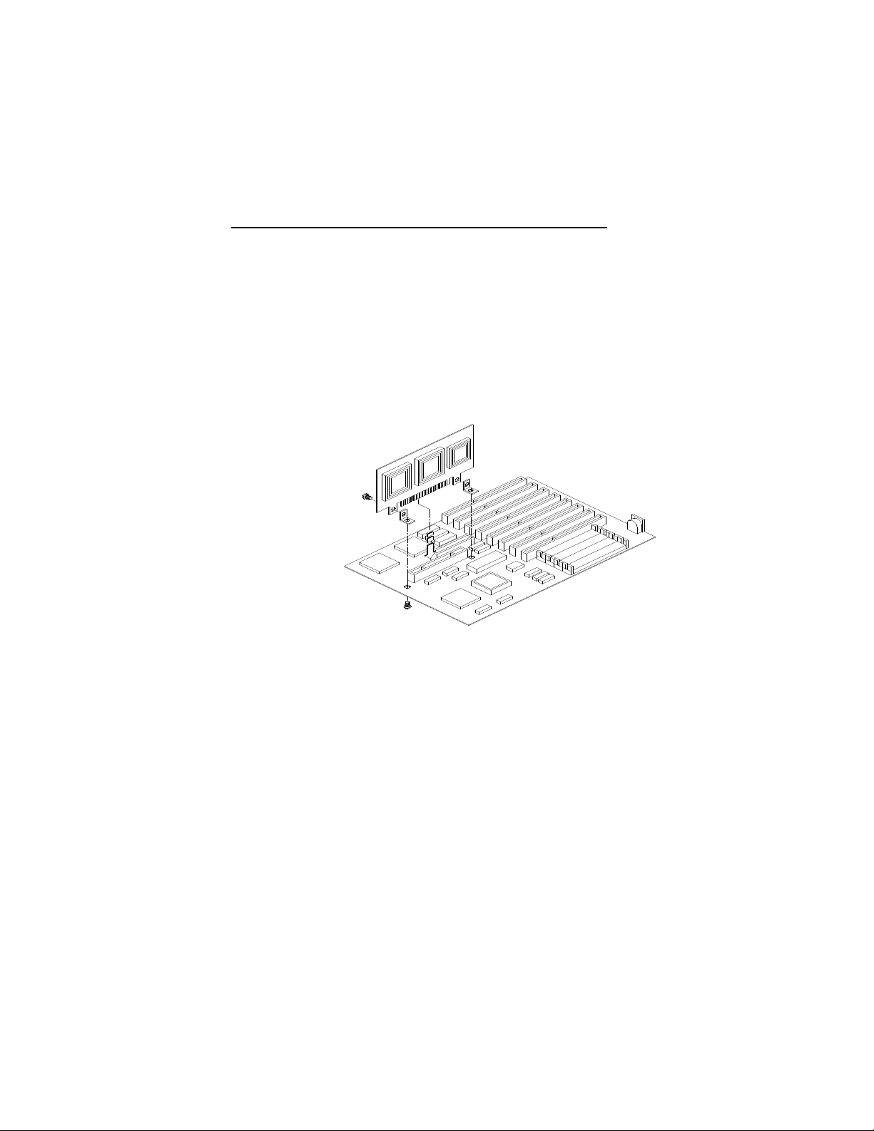
Step 8: Fasten the screw into the CPU Module and
the L-shape bracket. Insert the CPU module
into the slot, and then, under the system
board, fasten the screw into the system
board and the L-shape bracket which is
attached to the CPU Module. Please refer to
the picture below:
Step 9: Install the prepared EB3486-TN system
board into the case and replace the screws.
Step 10: Reattach all cards and connectors and replace
the system unit cover. Reconnect all power
Installation Overview u 2-4
Page 14

PUMA Station Board
cords and cables.
v Hardware Installation
Computer components are easily damaged by static
electricity. Static electrical discharge can damage your
system board, even though there are no signs of physical
damage. Be careful to handle the system board by its
edges. Do not touch any part of the circuitry, especially
the gold contacts, with your hands. Do all the preparation work on a static-free surface. Place the system
board on a static-free table with the components facing
up.
Memory Installation
The EB3486-TN system board can support 1MB to
128MB of memory using HSIMMs. HSIMM is an
acronym for High Density Single In-line Memory Module. A HSIMM consists of several RAM chips soldered
onto a small circuit board. A HSIMM connects with the
system board via a 72-pin card-edge connector.
The HSIMM sockets are divided into four banks which
are located on the main board. The SIM modules are
plug into the banks at the upper-left side of the station
board.
You will need 1 to 4 pieces of HSIM modules, depending on the amount of memory you intend to install.
Your system board can be configured to 1MB, 2MB,
3MB, 4MB, 6MB, 8MB, 9MB, 10MB, 11MB, 12MB,
14MB, 16MB, 20MB, 24MB, 28MB, 32MB, 36MB,
40MB, 44MB, 48MB, 56MB, 64MB, 68MB, 72MB,
80MB, 96MB, 100MB, 104MB, 112MB or 128MB of
onboard memory.
3-1 u Hardware Installation
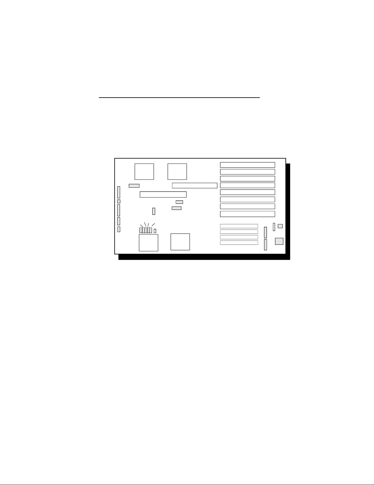
Page 15
EB3486-TN
To install the HSIM modules, first populate Bank 1,
then Bank 2 and so on. Failure to do so will cause the
system board to work improperly.
VESA Slot
CPU MODULE
l
BANK 0
l
BANK 1
l
BANK 2
l
BANK 3
Location of the SIMM Sockets on the Station Board
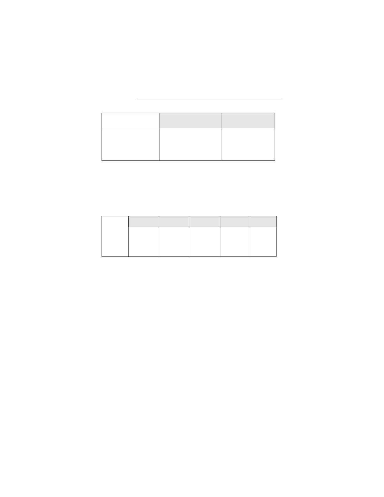
The following table summarizes the bank locations and
modules needed for corresponding memory sizes. Each
bank consists of 1 HSIMM socket.
Memory Bank 0 Bank 1 Bank 2 Bank 3
Size
1M 256K x 36 - - 2M 256K x 36 256K x 36 - 2M 512K x 36 - - 3M 256K x 36 256K x 36 256K x 36 4M 256K x 36 256K x 36 256K x 36 256K x 36
4M 512K x 36 512K x 36 - 4M 1M x 36 - - 6M 512K x 36 512K x 36 512K x 36 8M 512K x 36 512K x 36 512K x 36 512K x 36
Hardware Installation u 3-2
Page 16

PUMA Station Board
8M 1M x 36 1M x 36 - 8M 2M x 36 - - -
9M
2M x 36
256K x 36 - -
Memory Bank 0 Bank1 Bank 2 Bank 3
Size
10M 2M x 36 256K x 36 256K x 36 10M 2M x 36 512K x 36 - 11M 2M x 36 256K x 36 256K x 36 256K x 36
12M 2M x 36 512K x 36 512K x 36 12M 2M x 36 1M x 36 - 12M 1M x 36 1M x 36 1M x 36 14M 2M x 36 512K x 36 512K x 36 512K x 36
16M 2M x 36 1M x 36 1M x 36 16M 2M x 36 2M x 36 - 16M 1M x 36 1M x 36 1M x 36 1M x 36
16M 4M x 36 - - 20M 2M x 36 2M x 36 1M x 36 20M 4M x 36 1M x 36 - 24M 2M x 36 2M x 36 1M x 36 1M x 36
24M 4M x 36 1M x 36 1M x 36 24M 4M x 36 2M x 36 - 24M 2M x 36 2M x 36 2M x 36 28M 4M x 36 1M x 36 1M x 36 1M x 36
32M 2M x 36 2M x 36 2M x 36 2M x 36
32M 4M x 36 4M x 36 - 32M 8M x 36 - - 32M 4M x 36 2M x 36 2M x 36 36M 4M x 36 4M x 36 1M x 36 36M 8M x 36 1M x 36 - 40M 4M x 36 2M x 36 2M x 36 2M x 36
40M 4M x 36 4M x 36 1M x 36 1M x 36
40M 4M x 36 4M x 36 2M x 36 -
40M
3-3 u Hardware Installation
Page 17

EB3486-TN
64M 8M x 36 8M x 36 - -
64M 8M x 36 4M x 36 4M x 36 68M 8M x 36 8M x 36 1M x 36 -
Memory Bank 0 Bank1 Bank 2 Bank 3
Size
64M 16M x36 - - 72M 8M x 36 8M x 36 1M x 36 1M x 36
72M 8M x 36 8M x 36 2M x 36 80M 8M x 36 4M x 36 4M x 36 4M x 36
80M 8M x 36 8M x 36 2M x 36 2M x 36
80M 16M x 36 4M x 36 - 96M 8M x 36 8M x 36 8M x 36 96M 16M x 36 4M x 36 4M x 36 100M 8M x 36 8M x 36 8M x 36 1M x 36
104M 8M x 36 8M x 36 8M x 36 2M x 36
112M 8M x 36 8M x 36 8M x 36 4M x 36
112M 16M x 36 4M x 36 4M x 36 4M x 36
128M 8M x 36 8M x 36 8M x 36 8M x 36
128M 16M x 36 8M x 36 8M x 36 128M 16M x 36 16M x 36 - 128M 32M x 36 - - -
Bank Locations and Modules Needed
Hardware Installation u 3-4
Page 18
PUMA Station Board
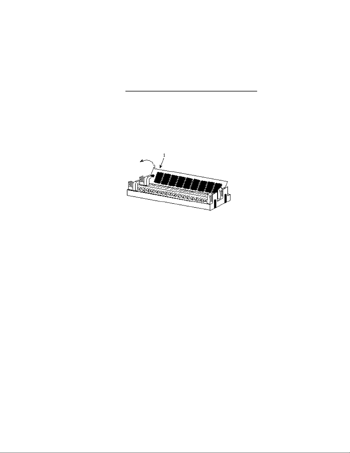
Installing the Modules
HSIMMs simply snap into a socket on the system board.
Pin 1 of the HSIMM must correspond with Pin 1 of the
socket.
1. Position the HSIM modules above the HSIMM
socket with the chips of the module facing the
center of the system board.
2. Seat the module into the bank. Make sure it is
completely seated in its socket before pressing the
module securely into the bank as shown above.
3-5 u Hardware Installation
Page 19
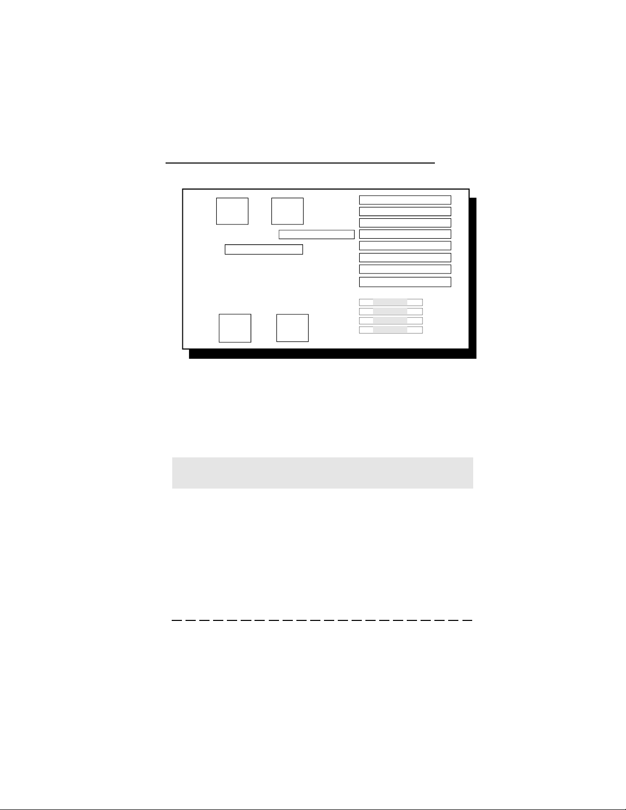
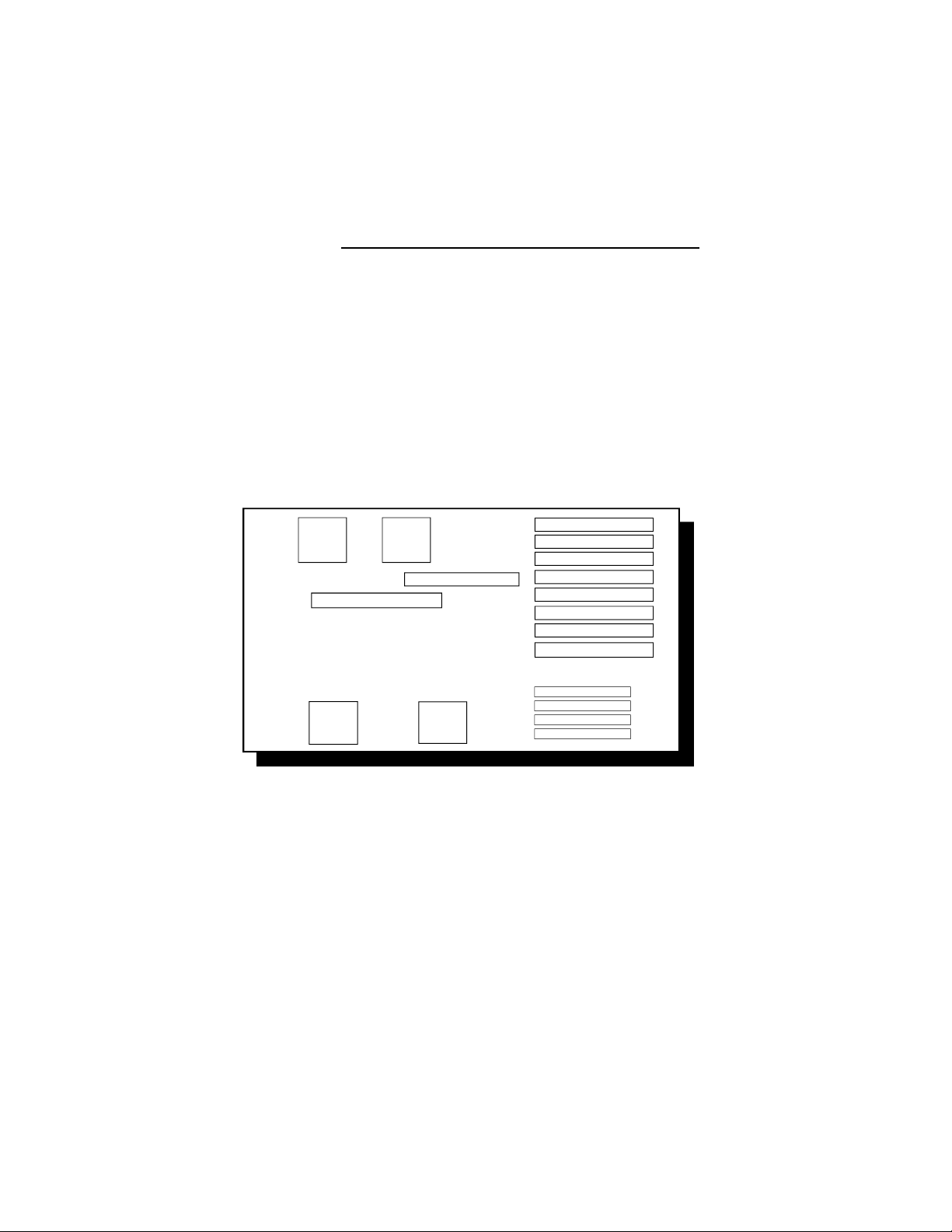
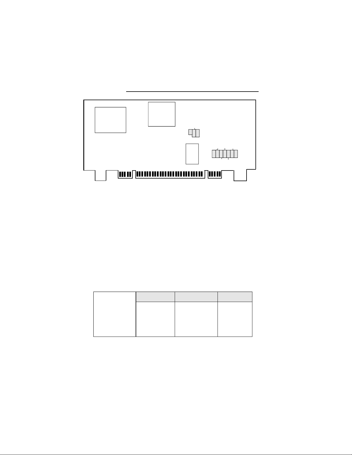
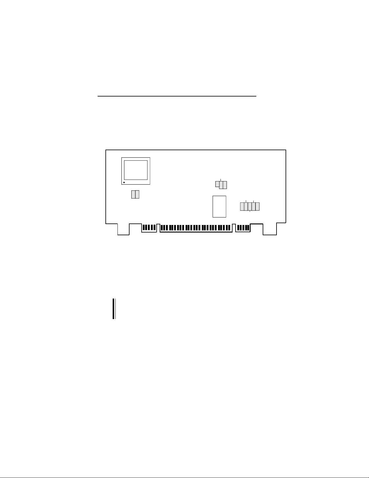
Board Configuration
The EB3486-TN is designed with jumpers and connectors onboard. Make sure that the jumpers are set correctly before installing the system board into your
system unit.
EB3486-TN
J18
J4
J1
J6
J2
J3
J14
J7
J15
CPU Module
J19
J16
J17
J20
VESA Slot
J13
J8
l
l
l
l
Location of Jumpers and Connector Pins
on the EB3486-TN
PL1
J11
PL2
J12
J10
Hardware Installation u 3-6
Page 20
PUMA Station Board
Jumper Settings
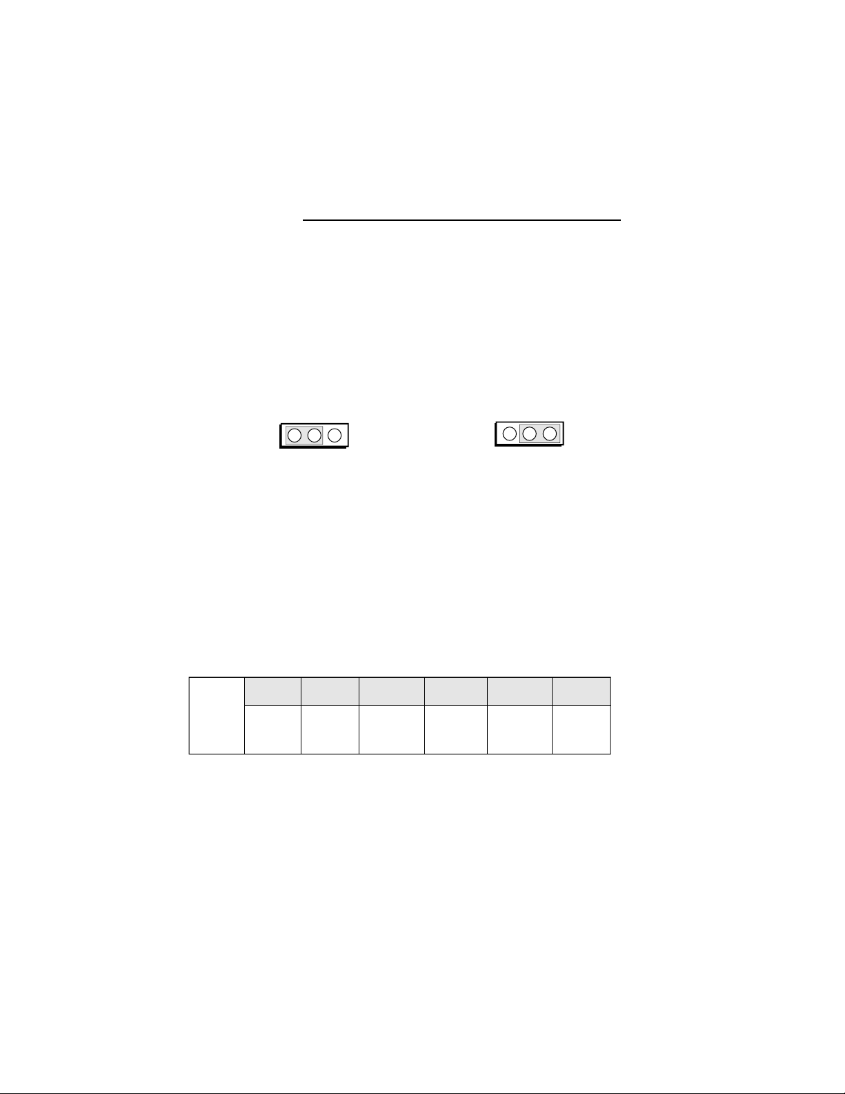
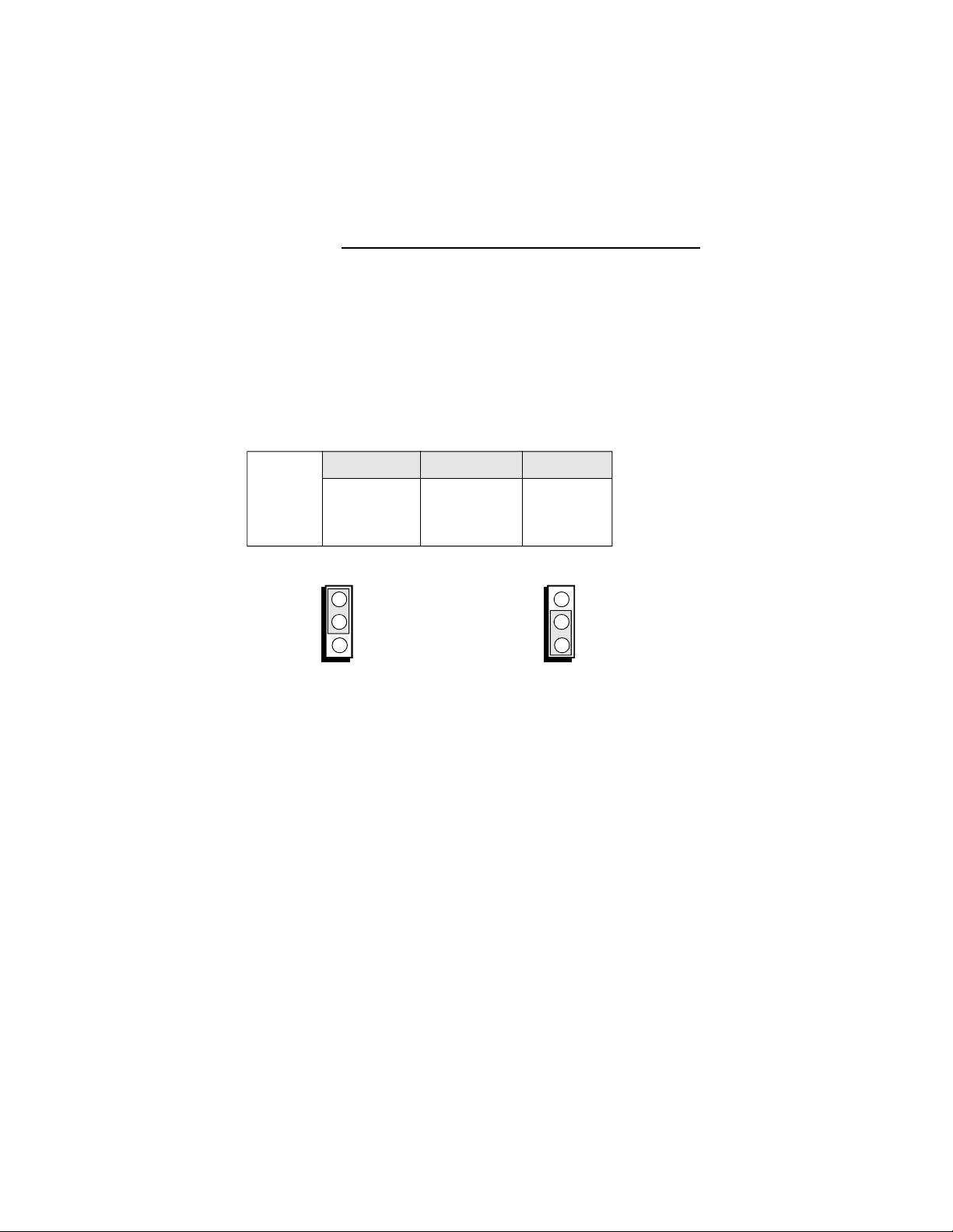
Jumper J8
Primary Display Selector
This jumper must match the type of display adapter
installed. If you change your video adapter, change this
jumper accordingly.
1 2 3
1-2 On: Color Display 2-3 On: Mono Display
(Default)
Jumper J7, J14 to J17, J19
CPU Module Select
Set the following jumpers according to the type of CPU
module installed on the station board. 486 refers to
486SX/DX/DX2 CPUs.
1 2 3
J7 J14 J15 J16 J17 J19
486 1-2 On 1-2 On 1-2 On 1-2 On 1-2 On 1-2 On
3-7 u Hardware Installation
Page 21
EB3486-TN
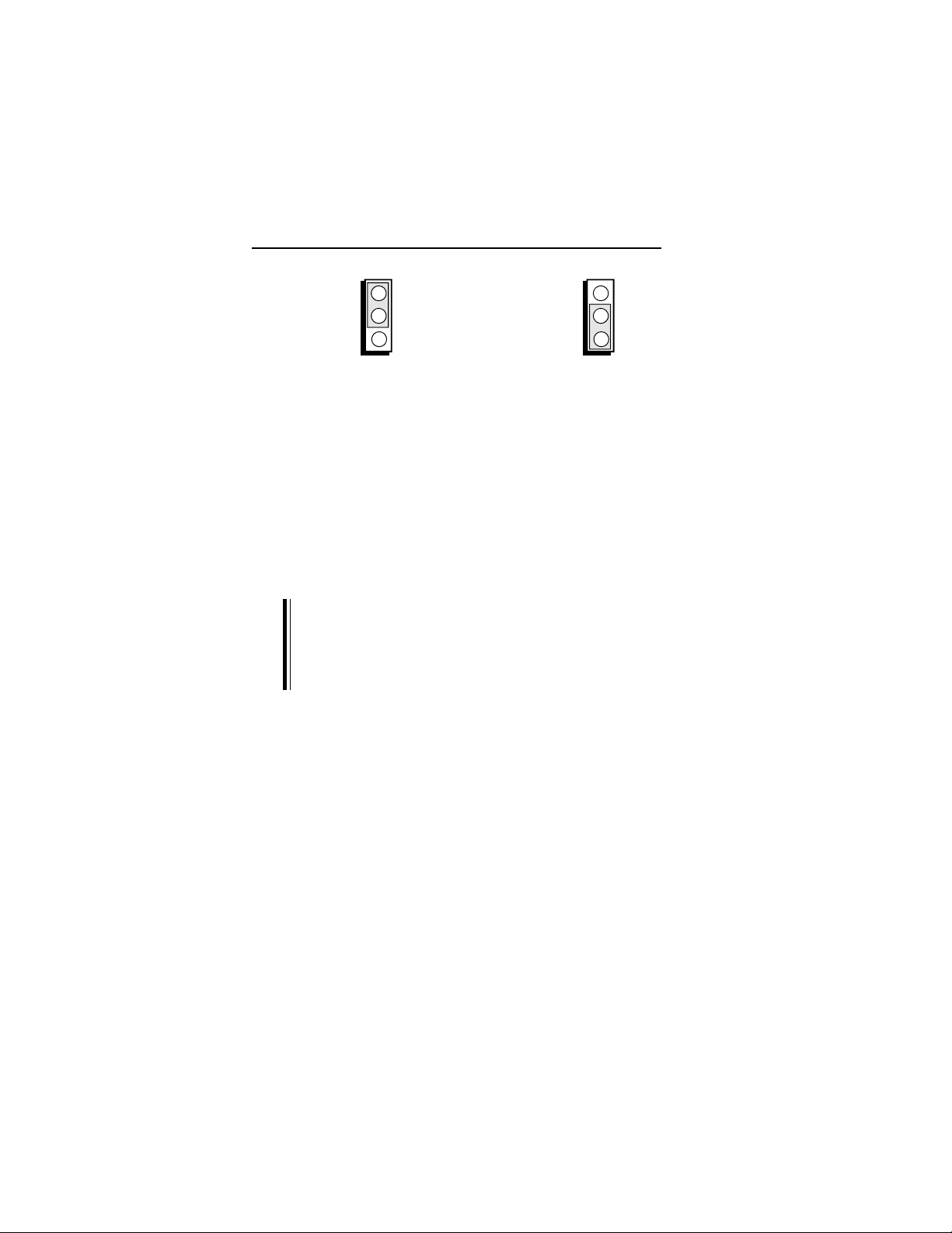
1
2
3
1-2: On
1
2
3
2-3: On
The jumpers below are for factory testing only and
should always be set to their default configuration.
Recon-figuring these jumpers will cause problems with
your EB3486-TN system board.
Jumper J3: 2-3 On
Jumper J13: Off
Jumper J20: On
Jumper J18: 1-2 On
Note:
There are no jumpers on this board to select between
internal and external batteries. The Dallas Real-time
clock we use has an battery built into the chip,
precluding the use of a battery on the system board.
Hardware Installation u 3-8
Page 22
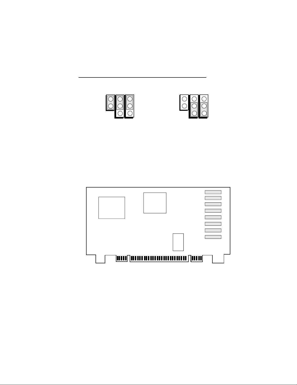
PUMA Station Board
v CPU Modules
The EB3486-TN station board comes with a CPU
module that is inserted in the CPU Module local-bus slot
on the station board. The types of CPU modules available are DBII-486SX/DX/DX2 and DBII-486C (SX/
DX/DX2). These modules support many of the CPU
speeds available in each CPU class. The CPU modules
are also equipped with sockets for coprocessors and are
easy to install, thus making upgradability easy and
affordable.
CPU MODULE local-bus slot
l
l
l
l
Location of the CPU Module Local-Bus Slot on the EB3486-TN
4-1 u CPU Modules
Page 23
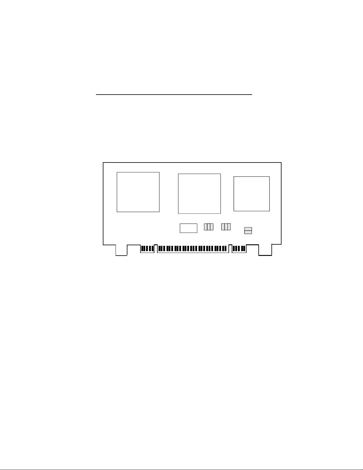
DBII-486SX/DX/DX2 CPU Modules
The following CPU's are supported by this module: 25/
33MHz 486SX, 25/33MHz 486DX and 50/66MHz
486DX2. An 80487SX and Weitek 4167 are also supported. If you have a 486SX CPU installed, an overdrive
processor could also be installed at a later date.
EB3486-TN
U1
U5
U6
J3
J5
J2
J4
J1
J6
J7
J8
DBII-486SX/DX/DX2 CPU Module
The DBII-486SX/DX/DX2 CPU Module has three
sockets: U1 (socket for 487SX/OverDrive Processor),
U5 (socket for 486SX/DX/DX2), U6 (socket for
WTL4167).
CPU Modules u 4-2
Page 24
PUMA Station Board
Jumper Settings
Jumpers JP2/JP3/JP4
CPU Select
Jumpers JP2/JP3/JP4 set the CPU modules to 486SX,
486DX or 486DX2, depending on which type of CPU is
installed. The default setting is 486DX.
486SX 486DX* 486DX2
JP2 2-3: On 1-2: On 1-2: On
JP3 2-3: On 1-2: On 1-2: On
JP4 2-3: On 1-2: On 1-2: On
1
2
3
1
2
3
1-2: On
Jumpers JP7/JP8
CPU Clock Select
4-3 u CPU Modules
2-3: On
Page 25
EB3486-TN
Set these jumpers according to the speed of CPU installed
on the CPU module. The default setting is 33MHz.
25MHz 33MHz*
JP7 2-3: On 1-2: On
JP8 1-2: On 1-2: On
1
2
3
1
2
3
1-2: On
The jumpers below are for factory testing only and
should always be set to their default configuration.
Jumpers JP1/JP5/JP6: 2-3 On
* Default setting
DBII-486C Rev. 0 CPU Modules
The DBII-486C Rev. 0 CPU Module supports the same
CPU speeds as the DBII-486SX/DX/DX2 CPU
modules. This CPU Module also supports up to 256K
of external cache.
2-3: On
CPU Modules u 4-4
Page 26
PUMA Station Board
U1
The DBII-486C Rev. 0 CPU Module has two sockets:
U1 (socket for 486DX, 486DX2, 486SX and 487SX/
OverDrive Processor), U9 (socket for Weitek
Coprocessor).
Jumper Settings
U9
J2
J1 J3
J9
DBII - 486C Rev. 0 CPU Module
J10
J5
J4 J6
J7
J8
Jumpers JP1 to JP3
CPU Select
Jumpers JP1/JP2/JP3 set the CPU module to 486SX,
487SX, or 486DX/DX2, depending on which type of
CPU is installed. The default setting is 486DX.
486DX/DX2* 1-2: On 1-2: On 2-3: On
486SX Off Off 1-2: On
OverDrive 1-2: On 2-3: On 2-3: On
Processor
4-5 u CPU Modules
JP1 JP2 JP3
Page 27
JP1 JP2 JP3 JP2 JP3JP1
On
* Default setting
Cache Configuration
You can configure DBII-486C Rev. 0 to three different
cache sizes: 64K, 128K, and 256K. 256K is the default
size. Use either 8K x 8 (25ns) or 32K x 8 (25ns)
SRAMs to upgrade your cache size. The figure below
shows the location of the SRAM sockets.
U1
EB3486-TN
1
2
3
Off
1
2
3
2-3: On1-2: On
U13
U14
U9
U15
U16
U17
U18
U19
U20
CPU Modules u 4-6
Page 28
PUMA Station Board
Cache Size U13 - U16 U17 - U20
64K 8K x 8 (25ns) 8K x 8 (25ns)
128K 32K x 8 (25ns) none
256K* 32K x 8 (25ns) 32K x 8 (25ns)
Jumper Settings for Cache Memory
Jumpers JP4 to JP8
Cache Size Setting
JP4 JP5 JP6 JP7 JP8
64K 2-3: On 2-3: On 2-3: On 1-2: On 1-2: On
128K 1-2: On 1-2: On 2-3: On 2-3: On N/A
256K* 1-2: On 1-2: On 1-2: On 2-3: On 2-3: On
The jumpers below are for factory testing only and should
always be set to their default configuration.
Reconfiguring these jumpers will cause problems with
your EB3486-TN system board.
Jumpers JP9 and JP10: 1-2 On
* Default setting
4-7 u CPU Modules
Page 29
DBII-486C Rev. B CPU Modules
The DBII-486C Rev. B CPU Module supports the same
CPU speeds as the DBII-486C Rev. 0 CPU modules.
ZIF
Socket
U1
EB3486-TN
J2
J3J1
J9 J10
J4
J5 J7
J8
J6
DBII - 486C Rev. B CPU Module
The DBII-486C Rev. B CPU Module has a 237 pin ZIF
socket: U1 (socket for 486SX, 486DX, 486DX2 and
487SX/Intel 486
TM
OverDrive Processor/Pentium
TM
OverDrive Processor).
Note:
DBII-486C Rev. B CPU Module does not support
Weitek coprocessor (4167).
CPU Modules u 4-8
Page 30

PUMA Station Board
Jumper Settings
Jumpers JP1 to JP3
CPU Select
(Refer to DBII-486C Rev. 0 CPU module jumper settings on
page 4-5).
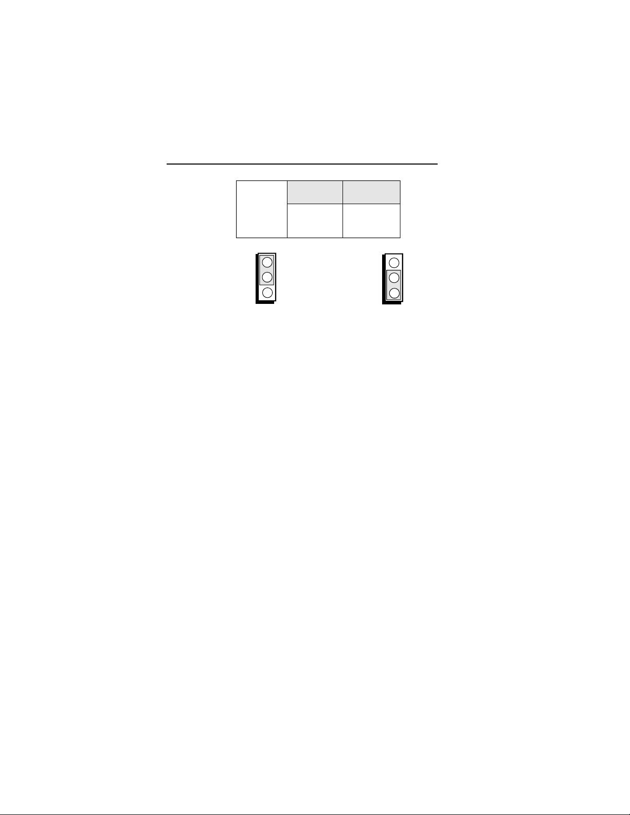
Jumper Block JP9 and JP10
CPU Voltage
The DBII-486C Rev. B supports 5 Volt CPUs. Optional
3.3 Volt CPUs are supported only if a regulator chip is
soldered on location U22. Set Jumper block JP9 and
JP10 according to the voltage of the CPU installed.
Warning:
If you are using a 3.3 Volt CPU, this jumper block must
be set to 3.3 Volt. Otherwise, the CPU will be
permanently damaged.
CPU Voltage JP9/JP10
* Default setting
4-9 u CPU Modules
5V CPU* 1-2: On
3.3V CPU 2-3: On
Page 31

EB3486-TN
JP10
JP9
1-2 On: 5 Volt CPU
(Default)
Cache Configuration
You can configure DBII-486C Rev. B to two different
cache sizes: 128K, and 256K. 256K is the default size.
Use 4 pieces 32K x 8 (25ns) SRAMs to upgrade your
cache. The figure below shows the location of the
SRAM sockets.
ZIF
Socket
U1
JP9 JP10
1
2
3
1
2
3
2-3 On: 3.3 Volt CPU
U13
U14
U15
U16
U17
U18
U19
U20
CPU Modules u 4-10
Page 32

PUMA Station Board
Cache Size U13 - U16 U17 - U20
128K 32K x 8 (25ns) none
256K* 32K x 8 (25ns) 32K x 8 (25ns)
Jumper Settings for Cache Memory
Jumpers JP4 to JP8
Cache Size Setting
JP4 JP5 JP6 JP7 JP8
128K 1-2: On 1-2: On 2-3: On 2-3: On N/A
256K* 1-2: On 1-2: On 1-2: On 2-3: On 2-3: On
* Default setting
4-11 u CPU Modules
Page 33

v Initial Setup Program
After you power up your system, the BIOS message will
appear on your screen and the memory count begins.
After the memory test, the message below will appear on
the screen if your CMOS setup is correct:
Enter CURRENT Password:
The default password is AMI. You have three chances
to type the correct password. If the password is still
incorrect after the third try, the system will lock up.
You must turn your system off and back on again to
restart it. You can change the password under the
change password option. Refer to the "Change Password" section for more information. A screen similar to
the one below will now appear. If the password option
is disabled, you directly access this screen.
EB3486-TN
Note:
The type of processor indicated in the Main Processor
information line is dependent on the type of CPU module installed.
Initial Setup Program u 5-1
Page 34

PUMA Station Board
AMI BIOS Setup Utilities
If you want to change your CMOS setup, or your
CMOS setup is incorrect, press <Del> when the message, "Hit <Del> if you want to run setup," appears on
the screen. Again, if you enabled the password option,
you will be prompted to the message below:
Enter CURRENT Password:
The default password is AMI. For information on how
to change the password, refer to the "Change Password"
section. After entering the correct password, the screen
below appears. If the password option is disabled, you
will directly access this screen.
Use the arrow keys to highlight the option you want and
hit <Enter>.
5-2 u Initial Setup Program
Page 35

Standard CMOS Setup
Before accessing this option, the warning message below
will appear on the screen:
This message warns you that if inappropriate modifications are made to the CMOS Setup, problems will
occur. Press <Enter> to continue or press <Esc> to
abort.
EB3486-TN
Note:
If your system fails after the setup procedure, power off
your system and turn it on again. Wait for the
message, "Hit <Del> if you want to run setup," to
appear and press <Del>.
If you press <Enter>, a screen similar to the one on the
next page will appear:
Initial Setup Program u 5-3
Page 36

PUMA Station Board
The upper right hand corner shows the base memory size
and extended memory size of your system. You cannot
alter these items, as your computer automatically detects
and displays them.
The left side of the screen lists the modifiable parameters.
You can change the date, time, hard disk drive (C and D)
type, type of floppy drive (A and B), primary display, and
keyboard options.
On the lower right hand side is a calendar that shows
your current date setting.
The box at the lower left provides information each
highlighted parameter.
5-4 u Initial Setup Program
Page 37

EB3486-TN
Navigation and menu selection instructions are located
below the information box. Use the up or down arrow
key to move between options. Once you have highlighted
the option you wish to change, use the <Page Up> or
<Page Down> key to view the available selections for
that option.
If you have added a hard drive, you must select the
appropriate drive type for the drive. The EB3486-TN has
46 pre-set types and one user-definable type.
The table in appendix G gives a complete listing of the
available drive types. Any given drive must be set to one
specific drive-type number. Please refer to you hard drive
documentation to find the appropriate type number.
If none of the pre-set types is appropriate for your hard
drive, choose type 47, which is the user-definable type.
To use this type, highlight either hard disk C or D, depending on your hard drive configuration. Use the <Page
Up> key until type 47 is showing. Fill in all the parameters as specified by the drive manufacturer. To move
between parameters, hit the <Enter> key.
When you are through making changes, press <Esc> to
return to the main menu.
Advanced CMOS Setup
Before accessing this option, the warning message found
on the next page appears on the screen:
Initial Setup Program u 5-5
Page 38

PUMA Station Board
This message warns you that if inappropriate modifications are made to the Advanced CMOS Setup,
problems will occur. Press <Enter> to continue or press
<Esc> to abort.
Note:
If your system fails after the setup procedure, power off
your system and turn it on again. Wait for the
message, "Hit <Del> if you want to run setup", to
appear and press <Del>.
If you press <Enter>, a screen similar to the one on the
next page will appear:
5-6 u Initial Setup Program
Page 39

EB3486-TN
Note:
The VL-Bus Adapter must be set to "Present" if there is
any local bus device installed.
The Memory Write buffer must be set to disable if any
problem occurs on the VL-Bus Adapter. If memory
write buffer is enabled, some VL-Bus adapters can
gain much performance benefit from it.
Use the arrow keys to move the highlight bar to the
options you wish to change or modify. Use the <Page
Up> or <Page Down> keys to make the corresponding
changes.
Set the password checking option to "Always" or
"Setup" if you want to enable this option. Setting it to
"Always" will prompt you for a password everytime you
cold boot your computer or access setup. When you set
the option to "Setup", you will be prompted for a
password only when trying to access setup.
Initial Setup Program u 5-7
Page 40

PUMA Station Board
The Boot Sector Virus Protection option may be set to
"enabled" or "disabled". When enabled, the BIOS issues
a warning when any program or virus sends a Disk Format command or attempts to write to the boot sector of
the hard disk drive.
Note:
Your system must have an American Megatrend Keyboard Controller BIOS, version F or later, for this option to work.
If the changes made are incorrect, or you change your
mind, press <F6> or <F7> to return to the default
settings. Press <Esc> after making the changes to
return to the main menu.
Auto Configuration with BIOS Defaults
If, for some reason, the CMOS becomes corrupted, the
system can be configured with the default values should
provide optimum performance for the system. You
should use these values unless you are having possible
hardware problems.
Highlight this option on the main menu and press <Enter>. The message below will appear.
Load BIOS Setup Default Values from ROM Table (Y/N)? N
Type "Y" and press <Enter> to return to the BIOS
setup default values. After pressing <Enter>, you will
be returned to the main menu.
5-8 u Initial Setup Program
Page 41

Auto Configuration with Power-on Defaults
The Power-on defaults are similar to the BIOS Setup
defaults. These defaults are the most stable values for
the system and should be used if you are having possible
hardware problems.
Highlight this option on the main menu and press <En-
ter>. The message below will appear.
Load Power-on Default Values from ROM Table (Y/N)? N
Type "Y" and press <Enter> to return to the Power-on
default values. After pressing <Enter>, you will be
returned to the main menu.
Change Password
The default password is AMI. If you want to change
the password, make sure that you set the Password
Checking Option to "Always" or "Setup" under CMOS
Advanced Setup. If the Password Checking Option is
not enable, the error message below will appear on the
screen:
EB3486-TN
<Password Option> must be enabled in Advanced CMOS Setup
Press any key to continue
Use the arrow keys to highlight the Change Password
Option and press <Enter>. The message below will
now appear:
Enter Current Password:
Initial Setup Program u 5-9
Page 42

PUMA Station Board
The preset password is AMI. Type AMI, unless the
password has been previously changed, and press
<Enter>. The message below will now appear:
Type in the the new password. You are limited to six
ASCII characters. If you type more than six characters,
you will get the following error message:
Pressing any key on the keyboard to return to the
message below:
Type in a password that is six characters long or
shorter. When done, you will be prompted to the
message below:
Enter NEW Password:
Error, press any key
Enter NEW Password:
Re-enter NEW Password:
You are asked to verify the new password. Type in
exactly the same password. Failure to do so will yield
the error message shown below:
Error, press any key
If you receive this error, you will have to start over.
After typing in the new password, the message below
will appear:
5-10 u Initial Setup Program
Page 43

Press the <Esc> key to return to the main menu. Use
the arrow keys to go to the "Write to CMOS and exit"
option to save the new password and reboot your
system.
Auto Detect Hard Disk
This option detects the hard disk parameters for the hard
disk drives installed in your system. Highlight this
option and press <Enter>. A screen similar to the
following one will appear.
EB3486-TN
New password installed
The screen displays the parameters detected and allows
you to accept or reject the parameters. Type "Y" and
press <Enter> to accept the parameters or press <Esc>
to abort. If you select "Y", the parameters for hard disk
Type 47 will be displayed in Standard CMOS Setup. If
you select "N", the parameters in the Standard CMOS
Setup will remain the same.
Hard Disk Utility
Initial Setup Program u 5-11
Page 44

PUMA Station Board
This option will format, set the interleave mode, and do a
media analysis of your hard disk drives. Highlight this
option and press <Enter>. A screen similar to the
following one will appear.
Note:
Do not use this utility with an IDE hard drive. Use of
this utility can severely damage your hard drive.
Use the arrow keys to select the desired options and
press <Esc> to exit when done.
Write to CMOS and Exit
When all the changes have been made, highlight this
option and press <Enter>. The message below will
appear:
Write to CMOS and Exit (Y/N)? N
Type "Y" and press <Enter>. The modifications you’ve
made will be written into the CMOS memory, and the
system will reboot. You will once again see the initial
5-12 u Initial Setup Program
Page 45

diagnostics on the screen. If you wish to make additional changes to the setup, press <Del> after memory
testing is done.
Do Not Write to CMOS and Exit
When you do not want to save the changes you've made,
highlight this option and press <Enter>. The message
below will appear:
Want to quit without saving(Y/N)? N
Type "Y" and press <Enter>. The system will reboot
and you will once again see the initial diagnostics on the
screen. If you wish to make any changes to the setup,
press <Del> after memory testing is done.
EB3486-TN
Initial Setup Program u 5-13
Page 46

PUMA Station Board
v EISA Configuration Utility
Overview
The EB3486-TN system board requires the use of the
EISA Configuration Utility (ECU). The ECU is used to
configure EISA (Extended Industry Standard Architecture) computer systems.
EISA system boards and EISA adapter cards are much
more complex than the designs of ISA (Industry Standard Architecture) boards and adapter cards, making the
setup of jumpers and switches more complicated. The
ECU was created to automate this configuration process.
The CFG files that come with each EISA expansion
board are copied onto the ECU diskette. The ECU then
stores this configuration data in the system's Extended
CMOS Memory. The CFG file tells the ECU what
choices the user has in configuring the card and what
system resources to reserve for the card. The
EB3486-TN system board uses the "DFI0300.CFG" file.
File Structure
The ECU uses three different files: the CFG, CMS and
INF files.
CFG Files
Each EISA expansion board comes with a CFG file. A
board's CFG file contains detailed information about the
board as well as the functions the board can perform.
For the EB3486-TN system board, choose the
"DFI0300.CFG" file to be configured.
6-1 u EISA Configuration Utility
Page 47

CMS File
The CMS file contains a copy of the configuration
information that is written into the system's Extended
CMOS Memory. Each CMS file should have a
corresponding INF file.
INF File
The INF file contains detailed information about a
configuration such as switch and jumper settings,
software statements, connection statements, and resource
allocation. The INF file is used by the "Display/Print"
command to recall information on a saved configuration.
Each INF file should have a corresponding CMS file.
Initial Configuration
Every EISA system board and expansion board comes
with a CFG file. Prior to running the ECU, make sure
that all CFG files for expansion boards you are using are
in the same directory as the ECU file. If you did not
receive the CFG file for your expansion board, please
contact your dealer or the board manufacturer.
EB3486-TN
If you are installing an EISA hard drive controller/SCSI
host adapter, you will need to run the ECU from a
bootable floppy diskette because the system will not see
the hard drive until the EISA expansion board is
configured. To run the ECU after the hard drive
controller/SCSI host adapter is installed:
1. Create a directory on the disk drive where you want
to install the EISA configuration files. Change to
this directory.
EISA Configuration Utility u 6-2
Page 48

PUMA Station Board
2. Copy your EISA Configuration Utility diskette and
the CFG files for all of your EISA boards to
this directory.
3. To run the ECU, make sure that you are in the
directory created in step 1 and type CFG.
Main Menu
The ECU outlines the six steps that involved in configuring a EISA system, steps 1, 2, 3 and 5 are optional. To
select a step, use the arrow keys to move to a step of
your choice and press <Enter>. You may also select a
step by pressing its number. If you are using a mouse,
move the mouse pointer to the selected option and click
the left-mouse button once.
Note:
For a mouse to work in the ECU, you must have a
previously installed mouse driver.
The utility also includes an online Help menu which may
be accessed anytime by pressing the <F1> key.
6-3 u EISA Configuration Utility
Page 49

EISA CONFIGURATION UTILITY, Release 2.01 - (C)1992 American Megatrends Inc.
Step 1: About EISA Configuration
Step 2: Add and Remove Boards
Step 3: Change Configuration Settings
Step 4: Save Configuration
Step 5: View Switch/Jumper Settings
Step 6: Exit
[Select=Enter] [Exit=Esc] [Help=F1] [Utilities=F9]
Step 1: About EISA Configuration
This step display information for users who are new to
EISA and EISA Configuration.
EB3486-TN
Step 2: Add and Remove Boards
This step is optional. Use this step to manually add or
delete boards not detected automatically. Most boards
are automatically detected and added by the ECU.
Choose Add and Remove Boards and a screen similar
to the one shown on the next page will appear.
Page 50

PUMA Station Board
This box allows you to add, remove or move boards.
Step 2 - Add and Remove Boards
System - DFI EB3486-TN EISA SYSTEM BOARD
Slot 1 - Empty
Slot 2 - Empty
Slot 3 - Empty
Slot 4 - Empty
Slot 5 - Empty
Slot 6 - Empty
Slot 7 - Empty
Slot 8 - Empty
- Press INSERT to add a board that was not deleted or has not been installed yet.
- Press DEL to remove the selected board.
- Press F7 to move the selected board to a different slot.
- Press Esc when finished with this step.
[Add=INSERT] [Remove=DEL] [Move=F7] [Done=ESC] [HELP=F1]
Add
This option allows you to add a new board to the
current configuration.
a. Press <Insert> to select the Add option and a screen
similar to the one shown below will appear.
Directory: A:\*.CFG
!DFI0300.CFG - DFI EB3486-TN EISA SYSTEM BOARD
!DFI1001.CFG - DFI EISANet - 500 EtherNet Adapter
!DFI0001.CFG - EISA SYSTEM BOARD
!DFI0200.CFG - EISA SYSTEM BOARD
Select the Board to Add
[Select=ENTER] [Cancel=ESC] [Add ISA=INSERT]
6-5 u EISA Configuration Utility
Page 51

EB3486-TN
b. Select the board you want to add and press <Enter>.
If you wish to add an ISA board, choose Add ISA
option by pressing <Insert> at the "Select the Board
to Add" screen. An ISA Board Database box
similar to the one shown on the screen below will
appear.
Note:
You must define an ISA board before it will appear
in the ISA Database definition box. See the "Define
ISA Board" section on page 6-21 of this manual for
further information.
If you do not want to add a board, choose Cancel to
go back to the Add and Remove Boards.
System - DFI EB3486-TN EISA SYSTEM BOARD
Slot 1 - Empty
Slot 2 - Empty
Slot 3 - Empty
Slot 4 - Empty
Slot 5 - Empty
Slot 6 - Empty
Slot 7 - Empty
Slot 8 - Empty
Step 2 - Add and Remove Boards
ISA Board Database
Select the ISA board to load or press <Esc> to exit.
a
[ ] WG-1200VL
- Press INSERT to add a board that was not deleted or has not been installed yet.
- Press DEL to remove the selected board.
- Press F7 to move the selected board to a different slot.
- Press Esc when finished with this step.
[Add=INSERT] [Remove=DEL] [Move=F7] [Done=ESC] [HELP=F1]
[Ok=ENTER] [Cancel=ESC]
Highlight the board you want to add in the configuration
and press <Enter>. A Slot Selection box similar to one
shown on the next page will appear.
EISA Configuration Utility u 6-6
Page 52

PUMA Station Board
You must select a slot for each adapter board. The slots
are listed in the recommended order of preference.
Select the slot that corresponds to the actual slot where
the adapter board being configured resides and press
<Enter>. Choose OK to continue the configuration
process.
Step 2 - Add and Remove Boards
Adding a board
Performing syntax check on "AMIFFF1.CFG
System - DFI EB3486-TN EISA SYSTEM BOARD
Slot 1 - Empty
Slot 2 - Empty
Slot 3 - Empty
Slot 4 - Empty
Slot 5 - Empty
Slot 6 - Empty
Slot 7 - Empty
Slot 8 - Empty
- Press INSERT to add a board that was not deleted or has not been installed yet.
- Press DEL to remove the selected board.
- Press F7 to move the selected board to a different slot.
- Press Esc when finished with this step.
[Add=INSERT] [Remove=DEL] [Move=F7] [Done=ESC] [HELP=F1]
Select a slot for:
WG-1200VL
Board slot type is ISA16.
Slot Type
Slots are listed in recommended order.
[Select=ENTER]
1 EISAYes
2 EISAYes
3 EISAYes
3 EISAYes
5 EISAYes
Slot Selection
Bus Master
Remove
This option allows you to remove a board from the
current configuration.
a. Select the board you want to remove from the
configuration and press <Delete>. A screen similar to
the one shown on the next page will appear.
6-7 u EISA Configuration Utility
Page 53

Step 2 - Add and Remove Boards
EB3486-TN
System - DFI EB3486-TN EISA SYSTEM BOARD
Do you really want to remove:
Slot 1 - Empty
WG-1200VL
Slot 2 - Empty
Slot 3 - Empty
Slot 4 - Empty
[Ok=ENTER] [Cancel=ESC]
Slot 5 - Empty
Slot 6 - Empty
Slot 7 - Empty
Slot 8 - Empty
- Press INSERT to add a board that was not deleted or has not been installed yet.
- Press DEL to remove the selected board.
- Press F7 to move the selected board to a different slot.
- Press Esc when finished with this step.
[Add=INSERT] [Remove=DEL] [Move=F7] [Done=ESC] [HELP=F1]
Confirm
b. Press <Enter> to confirm removal or <Esc> to cancel.
Move
This option allows you to move an adapter board to
another slot.
a. Select the board you want to move and press <F7>.
A Slot Selection box similar to the one shown on
the next page will appear.
EISA Configuration Utility u 6-8
Page 54

PUMA Station Board
Step 2 - Add and Remove Boards
System - DFI EB3486-TN EISA SYSTEM BOARD
Slot 1 - Empty
Slot 2 - Empty
Slot 3 - WG-1200VL
Slot 4 - Empty
Slot 5 - Empty
Slot 6 - Empty
Slot 7 - Empty
Slot 8 - Empty
- Press INSERT to add a board that was not deleted or has not been installed yet.
- Press DEL to remove the selected board.
- Press F7 to move the selected board to a different slot.
- Press Esc when finished with this step.
[Add=INSERT] [Remove=DEL] [Move=F7] [Done=ESC] [HELP=F1]
Select a slot for:
WG-1200VL
Board slot type is ISA16.
Slot Type
1 EISAYes
2 EISAYes
4 EISAYes
5 EISAYes
6 EISAYes
Slots are listed in recommended order.
[Select=ENTER]
b. Select the slot that corresponds to the actual slot
where the adapter board to be moved will reside,
and press <Enter>.
c. If you are finish with this step, choose Done to return
to the main menu.
Step 3: Change Configuration Settings
Slot Selection
Bus Master
Use this step to view or change configuration settings
for any board that is installed. If you skip this step, all
settings will remain set to their default values.
1. Choose Change Configuration Settings and a box
similar to the one shown on the next page will
appear.
6-9 u EISA Configuration Utility
Page 55

Step 3 - Change Configuration Settings
System - DFI EB3486-TN EISA SYSTEM BOARD
Slot 1 - DFI EISANet-500 EtherNet Adapter
Slot 2 - Empty
Slot 3 - Empty
Slot 4 - Empty
Slot 5 - Empty
Slot 6 - Empty
Slot 7 - Empty
Slot 8 - Empty
- This step is optional, you may skip it by pressing ESC and all configuration
settings will remain unchanged.
- Press ENTER to view or change a board's configuration settings.
- Press ESC when you are satisfied with the current settings.
[Select=ENTER] [Done=ESC] [Advanced Options=F9] [HELP=F1]
2. Select the slot you want to change from the
configuration and press <Enter>.
EB3486-TN
a. If you want to change your system memory,
choose System Board and press <Enter>. Select
System Board Memory and press <Enter>. A
System Board Memory Functions box similar to
the one shown on the next page will appear. If
you do not want to change anything, press <Esc>
to go back to the previous screen.
EISA Configuration Utility u 6-10
Page 56

PUMA Station Board
System Board Memory
Use SIMM Memory Module for the 486 System Board.
b. Select the memory that was installed in your
system board and press <Enter>.
Edit Settings for: DFI EB3486-TN EISA SYSTEM BOARD
System Board Memory Functions
( ) 1MB
( ) 2MB
( ) 3MB
( ) 4MB
( ) 6MB
( ) 8MB
( ) 9MB
( ) 10MB
( ) 11MB
( ) 12MB
( ) 14MB
( ) 16MB
( ) 20MB
( ) 24MB
[Select=ENTER] [Cancel=ESC]
Note:
You can only choose up to a maximum range of
64MB under EISA Configuration.
6-11 u EISA Configuration Utility
Page 57

EB3486-TN
Edit Settings for: DFI EISANet-500 Ethernet Adapter
DFI EISANet-500 I/O Addresses
Slot-Specific Only (Default)
DFI EISANet-500 EPROM
EPROM Disabled (Default)
Bus Master
Bus Release After Preempt
23 BCLK Cycles
DFI EISANet-500 Interrupt
Interrupt Edge/Level
Edge Triggered Interrupt
Ethernet
Packet Reception
Receive Own Packets
Connector Selection
Thin Ethernet (BNC1) [ETHERNet-500ECT]
[Done=ESC] [Change=ENTER] [Resources=F6] [PgUp] [PgDn] [Help=F1]
This menu box contains a list of all "choice" settings and
may have one or more resource settings. To change a
function's choice setting:
a. Use the up and down arrow keys to highlight a
function and then press <Enter>. The first section
"DFI EISANet-500 I/O Addresses" box was already
shown on the next page.
EISA Configuration Utility u 6-12
Page 58

PUMA Station Board
This board supports both slot-specific and ISA compatible I/O
DFI EISANet-500 I/O Addresses
addressing. The ISA mode should only be used for software
Slot-Specific Only (Default)
compatibility with ISA drivers.
DFI EISANet-500 EPROM
EPROM Disabled (Default)
Bus Master
Bus Release After Preempt
23 BCLK Cycles
[Select=Enter] [Cancel=ESC]
DFI EISANet-500 Iterrupt
Interrupt Edge/Level
Edge Triggered Interrupt
Ethernet
Packet Reception
Receive Own Packets
Connector Selection
Thin Ethernet (BNC1) [ETHERNet-500ECT]
[Done=ESC] [Change=ENTER] [Resources=F6] [PgUp] [PgDn] [Help=F1]
b. An option box will appear for you to choose.
Choose Slot-Specific Only (Default) and press
<Enter>.
Edit Settings for: DFI EISANet-500 Ethernet Adapter
( ) Slot-Specific only (Default)
( ) Slot-Specific and ISA
c. The same step should be done if you want to
change the following functions.
Note:
Some function may only have one choice
setting and therefore cannot be changed.
3. To change a function's Resource settings, use the
up and down arrow keys to highlight a function
and then press <F6>. When you are satisfied with
the current settings, press <Esc> to return to the
previous menu.
Note:
6-13 u EISA Configuration Utility
Page 59

EB3486-TN
Not all functions have resource settings.
Advanced Options
This option allows you to view detailed information
about the system board and the adapter boards installed
in the system.
a. Choose Advanced Options and a box similar to the
one shown below will appear.
Advanced Options
Global Resource Map
Board Details
System Details
System - DFI EB3486-TN EISA SYSTEM BOARD
Physical Board ID Map
Slot 1 - DFI EISANet-500 Ethernet Adapter
Slot 2 - Empty
Slot 3 - Empty
[Select=ENTER] [Done=ESC]
Slot 4 - Empty
Slot 5 - Empty
Slot 6 - Empty
Slot 7 - Empty
Slot 8 - Empty
- This step is optional, you may skip it by pressing ESC and all configuration
settings will remain unchanged.
- Press ENTER to view or change a board's configuration settings.
- Press ESC when you are satisfied with the current settings.
[Select=ENTER] [Done=ESC] [Advanced Options=F9] [HELP=F1]
Step 3 - Change Configuration Settings
Global Resource Map
The Global Resource Map allows you to view the
DMA Channels, IRQ line, I/O port address and
memory address of a board.
EISA Configuration Utility u 6-14
Page 60

PUMA Station Board
Board Details
This option informs you about the slot number, ID
and the board slot type of a board.
System Details
This option allows you to view the slot type, the
amperage used and EISA CMOS size of the boards
installed in the system.
Physical Board ID Map
The Physical Board ID Map allows you to view the
boards that are physically present in the system.
b. Press <Esc> to return to the main menu.
Step 4: Save Configuration
This option allows you to save the configuration in the
CMS and INF file.
a. After you have finished modifying the configuration,
go to the main menu and choose Save Configuration.
b. A box will appear informing you that the
configuration has been saved into the INF and CMS
file.
6-15 u EISA Configuration Utility
Page 61

Step 5: View Switch/Jumper Settings
This step allows you to set DIP switches and jumpers on
any board that is switch or jumper configurable.
a. After saving the configuration, choose View Switch/
Jumper Settings if you want to configure the switch
EISA CONFIGURATION UTILITY, Release 2.01 - (C)1992 American Megatrends Inc.
or jumper from your board. Press <Enter> and a box
similar to the one shown below will appear.
After saving the configuration it is important that
you do the following steps before using this system:
1.Note the switch and jumper settings verify that all switches and
jumpers on the boards in your system are set correctly. Some boards
have switches and jumpers that need to be set manually.
2.Note the software statements to see if any of the boards in your
configuration need special drivers to be loaded.
The screen that follow provide this information.
[ Ok=ENTER ]
Step 5: View Switch of Jumper Settings
Step 1: About EISA Configuration
Step 2: Add and Remove Boards
Step 3: Change Configuration Settings
Step 4: Save Configuration
Step 5: View Switch/Jumper Settings
Step 6: Exit
EB3486-TN
[Select=Enter] [Exit=Esc] [Help=F1] [Utilities=F9]
b. Press <Enter> to display the information. If your
board has no switches or jumpers, a box will appear
informing you that the board has no switches or
jumpers.
EISA Configuration Utility u 6-16
Page 62

PUMA Station Board
Page 1 of 6: Switches and Jumpers for Slot 0
c. To print the configuration, press <F7> and a Confirm
Print box similar to the one shown on the next page
Slot 0 - DFI EB3486-TN EISA SYSTEM BOARD
will appear.
This board has no
[Done=ESC] [Print=F7] [PgUp] [PgDn] [Help=F1]
d. Type the filename you want to print and press
<Enter>.
Switch/Jumper View
Confirm Print
Print to: (•) Printer
( ) File
Filename: Config. PRN
Ok=ENTER Cancel=ESC
e. Press <Esc> to return to the main menu.
Step 6: Exit
This step exits to the operating system. If any
configuration settings were changed, you are given the
option of rebooting the system so that the system
settings will take effect.
a. From the menu option, choose Exit and press
<Enter>. A box will appear asking “Do you
really want to exit?”
Choose:
6-17 u EISA Configuration Utility
Page 63

Yes - to exit to DOS.
Cancel - to return to the main menu.
Reboot - Reboot the system so that changes will
take effect.
Utilities Configuration
This screen controls how a configuration is produced.
Several options are available, each one can be enabled or
disabled by pressing SPACE when an option is
highlighted. To configure the Utilities:
EISA CONFIGURATION UTILITY, Release 2.01 - (C)1992 American Megatrends Inc.
From the main menu, press <F9> and a Utilities box
similar to the one shown below will appear.
Press <Space> to change settings.
[ ] Remote Mode (make a configuration for another system)
[ ] Advanced/Dealer Mode (show functions marked as EXP)
[ ] Force new configuration (ignore previous settings)
[ ] Load CFG files manually from directory list
[ ] Load CFG files listed in CFGLIST.DAT
[ ] Ignore ID mismatches between installed boards and CMOS
[ F5 ] = Restore configuration from backup (CMS file)
[ F6 ] = Display Physical Board ID Map
[ F7 ] = Define ISA Board
[OK=ENTER] [Cancel=ESC]
Step 6: Exit
EB3486-TN
Utilities
[Select=Enter] [Exit=Esc] [Help=F1] [Utilities=F9]
Remote Mode
The Remote Mode of the configuration should be turned
off if you are working on this computer. If you want to
produce a configuration for a computer other than this
one, turn on the Remote Mode. If Remote Mode is off,
EISA Configuration Utility u 6-18
Page 64

PUMA Station Board
configuration information will be stored in this
computer's EISA CMOS RAM as well as a CMS file
and INF file.
If Remote Mode is on, the configuration will be stored
in the files only. These files can be copied to another
computer and the configuration can be copied to that
system's EISA CMOS RAM using the “Restore
configuration from backup” option on this screen.
Advanced Dealer
Some EISA boards have CFG files that contain option
that are not ordinarily configured by end users. If this
mode is turned on, any functions that are marked as
EXP (expert) will be visible and can be changed.
Force New Configuration
When turned on, this mode will ignore any existing
configuration settings in CMOS or in the CMS file. All
settings will be set to their defaults.
Load CFG Files Manually from Directory List
When this mode is turned on, the ECU will not
automatically detect and add boards to the configuration.
You will be prompted to select boards one by one.
Load CFG Files Listed in CFGLIST.DAT
If you prefer to specify a list of CFG files to load, you
may create a file called CFGLIST.DAT that contain the
filename of the CFG files to be added. Turning this
option on causes the ECU to use this file.
6-19 u EISA Configuration Utility
Page 65

EB3486-TN
Ignore ID Mismatches Between Installed Boards and
CMOS
Normally the ECU will only configure boards that are
physically present in the system. If a board was present
in a previous configuration but was then physically
removed, the ECU will normally not load the CFG files
for this board. Turning this option on causes the ECU
to load CFG files for all boards that were in the previous
configuration regardless of whether or not they are
physically installed.
EISA Configuration Utility u 6-20
Page 66

PUMA Station Board
Define ISA Board
In addition to EISA adapter boards, you can install ISA
adapter boards by choosing this option. Most ISA
adapter boards do not have a CFG file. Without a CFG
file, the ECU cannot automatically reserve system
resources for ISA adapter boards. These boards must be
configured manually. To configure an ISA board:
1. Choose Configure Define ISA Board and an ISA
Board Definition box similar to the one shown below
will appear.
Board Name: WG-1200VL
Manufacturer: DFI
Board Type: Slot Type:
[Save=F10] [Load=F9] [New=F2] [Delete=F4] [Quit=ESC]
( ) Video Board
( ) Multifunction Board
( ) Mass Storage Device
DMA
-
-
-
-
ISA Board Definition
IRQ Ports Memory
-
-
-
-
-
-
-
-
-
-
-
-
-
-
-
-
-
-
-
-
-
-
-
( ) 16 bit
( ) 8 bit
( ) 8 or 16 bit
6-21 u EISA Configuration Utility
Page 67

EB3486-TN
2. Highlight "Board Name" and press <Enter>. The
cursor will appear for you to type-in the name of the
board. After typing-in the board name, press
<Enter>.
3. Highlight "Manufacturer" and press <Enter>. The
cursor will appear for you to type-in the name of the
manufacturer. After typing-in the manufacturer's
name, press <Enter>.
4. Highlight "Board Type" and press <Enter>. Select
theappropriate option for the board and press
<Enter>.
5. Highlight "Slot Type" and press <Enter>. Select the
slot type appropriate for the board and press <Enter>.
6. It is necessary to define an ISA board when you want
to prevent other boards in the system from using the
same IRQ levels, DMA channels, I/O Port address or
Memory address that your ISA board uses.
"DMA" allows you to define up to four (4) DMA
channels.
a. Select one of the DMA options and press
<Enter>. The ISA DMA Definition box similar
to the one shown on the next page will appear.
EISA Configuration Utility u 6-22
Page 68

PUMA Station Board
Board Name: WG-1200VL
Manufacturer: DFI
Board Type: Slot Type:
[Save=F10] [Load=F9] [New=F2] [Delete=F4] [Quit=ESC]
( ) Video Board
( ) Multifunction Board
( ) Mass Storage Device
DMA
-
-
-
-
ISA Board Definition
ISA DMA Definition
[ ] [ ] 1
[ ] 2
[ ] 3
[ ] 4
[ ] 5
[ ] 6
[ ] 7
Size:
Timing:
-
-
-
-
-
-
-
-
[ ] Byte
[ ] Word
[ ] Default
[ ] Type A
[ ] Type B
Channel:
-
-
-
-
[Ok=ENTER] [Cancel=ESC] [Erase=F4]
-
-
-
( ) 16 bit
( ) 8 bit
( ) 8 or 16 bit
-
-
-
-
-
-
-
-
b. Move the cursor to the appropriate DMA channel,
size and timing of the ISA board, and press
<Enter>.
c. Choose OK to save the changes you have just
made.
d. Choose Erase to delete the previously saved DMA
definition.
e. Choose Cancel to return to the ISA Board
Definition box without saving the changes.
6-23 u EISA Configuration Utility
Page 69

EB3486-TN
7. "IRQ" allows you to define up to seven (7) IRQ
levels. Select one of the IRQ options and press
<Enter>.
a. An ISA IRQ Definition box similar to the one
shown below will appear.
Board Name: WG-1200VL
Manufacturer: DFI
Board Type: Slot Type:
[Save=F10] [Load=F9] [New=F2] [Delete=F4] [Quit=ESC]
( ) Video Board
( ) Multifunction Board
( ) Mass Storage Device
DMA
-
-
-
-
ISA Board Definition
Level:
ISA IRQ Definition
Trigger:
[ ] [ ] 3
[ ] 4
[ ] 5
[ ] 6
[ ] 7
[ ] 9
[ ] 10
IRQ
[ ] 11
[ ] 12
-
[ ] 14
-
[ ] 15
-
-
-
[OK=ENTER] [Cancel=ESC] [Erase=F4]
-
-
[ ] Edge
[ ] Level
Ports Memory
-
-
-
-
-
-
-
-
( ) 16 bit
( ) 8 bit
( ) 8 or 16 bit
-
-
-
-
-
-
-
-
b. Select the appropriate IRQ level and type of
interrupt trigger to be used. Press <Enter>.
c. Choose OK to save the changes you have just
made.
d. Choose Erase to delete the previously saved IRQ
definition.
e. Choose Cancel to return to the ISA Board
Definition box without saving the changes.
EISA Configuration Utility u 6-24
Page 70

PUMA Station Board
8. "Ports" allows you to define up to eight (8) ranges of
I/O ports addresses.
a. Select one of the I/O Port options and press
<Enter>. The ISA Port Definition box similar to
the one shown below will appear.
Board Name: WG-1200VL
Manufacturer: DFI
Board Type: Slot Type:
[Save=F10] [Load=F9] [New=F2] [Delete=F4] [Quit=ESC]
( ) Video Board
( ) Multifunction Board
( ) Mass Storage Device
DMA
[OK=ENTER] [Cancel=ESC] [Erase=F4]
-
-
-
-
ISA Board Definition
ISA Port Definition
Size:
Start:
0
End:
0
IRQ Ports Memory
-
-
-
-
-
-
-
[ ] Byte
h
[ ] Word
h
-
-
-
-
-
-
-
-
( ) 16 bit
( ) 8 bit
( ) 8 or 16 bit
-
-
-
-
-
-
-
-
b. Select the starting and ending port address and the
timing setting of the selected port address. Press
<Enter>.
c. Choose OK to save the changes you have just
made.
d. Choose Erase to delete the previously saved Port
definition.
e. Choose Cancel to return to the ISA Board
Definition box without saving the changes.
6-25 u EISA Configuration Utility
Page 71

9. "Memory" allows you to define up to eight (8)
memory addresses.
a. Select one of the Memory options and press
<Enter>.An ISA Memory Definition box similar
to the one shown below will appear.
EB3486-TN
Board Name: WG-1200VL
Manufacturer: DFI
Board Type: Slot Type:
[Save=F10] [Load=F9] [New=F2] [Delete=F4] [Quit=ESC]
( ) Video Board
( ) Multifunction Board
( ) Mass Storage Device
Address:
DMA
-
-
-
-
ISA Board Definition
ISA Memory Definition
0 KB
Size:
0 h
[ ] RAM
IRQ Ports Memory
[ ] ROM
-
[ ] Don't Cache
-
[ ] Cache
-
-
-
[OK=ENTER] [Cancel=ESC] [Erase=F4]
-
-
Use:
Width:
-
Decode:
-
-
-
-
-
-
-
( ) 16 bit
[ ] System
( ) 8 bit
[ ] Expanded
( ) 8 or 16 bit
[ ] Other
[ ] Virtual
[ ] Byte
[ ] Word
-
[ ] 24 Bit
-
[ ] 20 Bit
-
-
-
-
-
-
b. Select the appropriate options in the ISA Memory
Definition box and press <Enter>.
c. Choose OK to save the changes you have just
made.
d. Choose Erase to delete the previously saved
Memory definition.
e. Choose Cancel to return to the ISA Board
Definition box without saving the changes.
EISA Configuration Utility u 6-26
Page 72

PUMA Station Board
10. After you have finished configuring the board,
choose Save to save the configuration in an ISA
CFG file.
11. Choose Load to edit a previously saved ISA CFG
file. A Load ISA Board Definition box similar to
the one shown on page 6-21 will appear. Highlight
the ISA board to be edited and press <Enter>.
12. Choose New to start a new ISA board configuration.
13. Choose Delete to remove an ISA board definition
from the ECU's internal ISA board database. An
ISA Board Database box similar to the one shown
below will appear.
Board Name: WG-1200VL
Manufacturer: DFI
Board Type: Slot Type:
[Save=F10] [Load=F9] [New=F2] [Delete=F4] [Quit=ESC]
( ) Video Board
( ) Multifunction Board
Select the ISA board to delete or press <Esc> to exit.
( ) Mass Storage Device
a
DMA
[ ] WG-1200VL
-
-
-
-
[Ok=ENTER] [Cancel=ESC]
ISA Board Definition
ISA Board Database
IRQ Ports Memory
-
-
-
-
-
-
-
14. Quit returns you to the main menu without saving
any changes.
6-27 u EISA Configuration Utility
( ) 16 bit
( ) 8 bit
( ) 8 or 16 bit
-
-
-
-
-
-
-
-
-
-
-
-
-
-
-
-
Page 73

v DEMM 386 Software Driver
DEMM 386 is a software driver that is used on the
EB3486-TN system board to translate extended memory
into expanded memory.
Copy the DEMM386.SYS driver from the provided
diskette into your root directory. After copying the
driver, add a line to your CONFIG.SYS file using the
following syntax:
DEVICE = DEMM386.SYS [/B=xxxx] [/H=yy] [/S=zz] [/
T=tttt]
[/X=aaaa-bbbb] [/I=cccc-dddd] [/L]
Note:
This line should be placed before any other drivers that
use extended memory. The parameters enclosed in
brackets "[" and "]" are optional and do not need to be
included. Do not include the "[" and "]" when typing
any parameters.
EB3486-TN
xxxx is the EMS page frame base address in
hexadecimal. In expanded memory management,
a contiguous 64KB page frame segment must be
reserved. The following are valid page frame
addresses; C000, C400, C800, CC00, D000,
D400, D800, DC00 and E000. The default page
frame address is E000.
yy is the maximum handle numbers (in hexadecimal)
to be reserved. The default value is 40H (64 in
decimal).
zz is the maximum number of contexts (in
hexadecimal) to be reserved. The default value is
DEMM 386 Software Driver u 7-1
Page 74

PUMA Station Board
40H (64 in decimal).
tttt specifies an area of the extended memory (in
kilobytes) to be reserved that will not be used by
the EMS driver. Without the /T option, all of
the extended memory will be used as expanded
memory.
aaaa-bbbb specifies that a certain range of memory
should be excluded from EMS mapping. aaaa is
the starting segment address and bbbb is the
ending segment address of the range. For
example, if a network adapter in your system
occupies memory from D0000 to D3FFF, specify
/X=D000-D3FF to exclude this range from EMS
mapping.
cccc-dddd specifies that a certain range of memory
should be included in EMS mapping. cccc is the
starting segment address and dddd is the ending
segment address of the range. This option is
very useful if you want the EMS driver to utilize
unused video area. For example, if a Hercules
graphics adapter is installed in your system, the
memory range between A0000 to AFFFF is not
used at all. By specifying /I=A000-AFFF, the
EMS driver will utilize the area for EMS mapping.
/L specifies that the backfill area (384KB from
4000:0 to 9000:FFFF) will be used exclusively as
conventional memory. The EMS driver will not
be able to use this area as page frames or EMS
pages.
7-2 u DEMM 386 Software Driver
Page 75

v Troubleshooting Checklist
If you experience difficulty with the EB3486-TN system
board, please refer to the checklist below. If you still
cannot isolate the problem, please contact your dealer.
1) Check the jumper settings to ensure that the jumpers
are properly set. If in doubt, refer to the “Board
Configuration” section.
2) Verify that all SIM modules are seated securely into
the bank sockets.
3) Make sure that the SIM modules are in the correct
location.
4) Check that all populated memory banks are
completely filled. If not, fill them completely.
5) If your board fails to function, place the board on a
flat surface and seat all socketed components (gently
press each component into the socket).
EB3486-TN
Troubleshooting Checklist u 8-1
Page 76

PUMA Station Board
v Appendix A: Types of Modules
The EB3486-TN system board allows you to populate
memory with 256Kx36, 512Kx36, 1Mx36, 2Mx36,
4Mx36 and 8Mx36 SIM modules. The following modules have been tested with this board.
For SIM 256Kx36 Modules
Brand Chip Number
Hitachi HM514280-JP8
Oki M516256B-80J
Fujitsu 81C4256-80
For SIM 512Kx36 Modules
Brand Chip Number
Panasonic MN41C256SJ-08
Hitachi HM514280-JP8
OKI M514256B-80J
NEC 44256-70
For SIM 1Mx36 Modules
Brand Chip Number
Toshiba TC514400ASJL-70
Fujitsu 814400-80
OKI M511000B-70J
NEC 424400-80
A-1 u Appendix A
Page 77

For SIM 2Mx36 Modules
Brand Chip Number
Fujitsu 814400-80
OKI M511000B-70J
EB3486-TN
Appendix A u A-2
Page 78

PUMA Station Board
v Appendix B: System Error Report
During the POST (Power On Self Test) routines, which
are performed each time the system is powered on,
errors may occur. Errors can be fatal or non-fatal.
Fatal Errors
Fatal errors are those which will not allow a system to
continue the boot-up procedure. If a fatal error occurs,
you should contact your dealer for repair.
Beep Count Error Message
1 Refresh Failure
2 Parity Error
3 Base 64KB Memory Failure
4 Timer Not Operational
5 Processor Error
6 8042 - Gate A20 Failure
7 Processor Exception Interrupt Error
8 Display Memory Read/Write Error
9 ROM Checksum Error
10 CMOS Shutdown Read/Write Error
B-1 u Appendix B
Page 79

Non-Fatal Errors
Non-fatal errors are those which, in most cases, allow
the system to continue the boot-up process. The error
messages normally appear on the screen.
Error Message
1. CH-2 Timer Error
2. INTR #1 Error
3. INTR #2 Error
4. CMOS Battery State Low
5. CMOS Checksum Failure
6. CMOS Options Not Set
7. CMOS Display Type Mismatch
8. Display Switch Not Proper
9. Keyboard is Locked...Unlock It
10. Keyboard Error
11. KB/Interface Error
12. CMOS Memory Size Mismatch
13. FDD Controller Failure
14. HDD Controller Failure
15. C: Drive Error
16. D: Drive Error
17. C: Drive Failure
18. D: Drive Failure
19. CMOS Time & Date Not Set
20. Cache Memory Bad, Do not Enable Cache
21. 8042 Gate-A20 Error
22. Address Line Short!
23. DMA #2 Error/DMA #3 Error/DMA Error
24. No ROM Basic
25. Diskette Boot Failure/Invalid Boot Diskette
26. On Board Parity Error/Off Board Parity Error/
Parity Error????
EB3486-TN
Appendix B u B-2
Page 80

PUMA Station Board
v Appendix C: Memory & I/O Maps
Memory Address Map
Address Name Function
00000000 to 640K System System Board Memory
0009FFFF Board RAM
000A0000 to 128K Video Reserved for Graphics Display
000BFFFF Display Memory Memory
000C0000 to 128K I/O Reserved for ROM on I/O
000DFFFF Expansion ROM Adapter Card
000E0000 to 64K Reserved Duplicated Code Assignment at
000EFFFF on System Board Address FE0000
000F0000 to 64K ROM on Duplicated Code Assignment at
000FFFFF the System Board Address FF0000
00100000 to Maximum System Board Memory
07FFFFFF Memory 126.875M
FFFE0000 to 64K Reserved Duplicated Code Assignment at
FFFEFFFF on System Board Address 0E0000
FFFF0000 to 64K ROM on Duplicated Code Assignment at
FFFFFFFF the System Board Address 0F0000
C-1 u Appendix C
Page 81

I/O Address Map
I/O Address Function
000-01F DMA Controller 1, 8237A-5
020-03F Interrupt Controller 1, 8259A, Master
040-05F Timer, 8254-2
060-06F 8742 (Keyboard Controller)
070-07F Real-time Clock, NMI
080-09F DMA Page Memory, 74LS612
0A0-0BF Interrupt Controller 2, 8259A
0C0-0DF DMA Controller 2, 8237A-5
0E8 Shadow RAM and Cache Control Bit
0F0 Clear Numeric Processor
0F1 Reset Numeric Processor Extension
0F8-0FF Numeric Processor Extension
1F0-1F8 Fixed Disk
200-207 Game I/O
278-27F Parallel Printer Port 2
2F8-2FF Serial Port 2
300-31F Prototype Card
360-36F Reserved
378-37F Parallel Printer Port 1
380-38F SDLC, Bisynchronous 2
3A0-3AF Bisynchronous 1
3B0-3BF Monochrome Display and Printer Adapter
3C0-3CF Reserved
3D0-3DF Color/Graphics Monitor Adapter
3F0-3F7 Diskette Controller
3F8-3FF Serial Port 1
EB3486-TN
(Non-maskable Interrupt) Mask
Extension Busy
Note:
The I/O address hex 000 to 0FF are reserved for the
system board I/0. Hex 100 to 3FF are available on the
I/O channels.
Appendix C u C-2
Page 82

PUMA Station Board
v Appendix D: EISA I/O Pin Assignments
F B E A
1 1 1 1
Note:
Rows A, C, B and D are ISA contacts
Rows E,G, F and H are EISA contacts
D-1 u Appendix D
313131
1 1 1 1
191919
H D G C
31
19
Page 83

I/O Pin Signal Name I/O
E1 -CMD O
E2 -Start I/O
E3 Exrdy I/O
E4 -EX32 I/O
E5 Gnd Gnd
Access Key
E7 -EX16 I/O
E8 -SLBurst I
E9 -MSBurst I/O
E10 W-R I/O
E11 Gnd Gnd
E12 Reserved
E13 Reserved
E14 Reserved
E15 Gnd Gnd
Access Key
E17 -BE1 I/O
E18 -LA31 I/O
E19 Gnd Gnd
E20 -LA30 I/O
E21 -LA28 I/O
E22 -LA27 I/O
E23 -LA25 I/O
E24 Gnd Gnd
Access Key
E26 LA15 I/O
E27 LA13 I/O
E28 LA12 I/O
E29 LA11 I/O
E30 Gnd Gnd
E31 LA9 I/O
F1 Gnd Gnd
F2 +5V Power
F3 +5V Power
F4 XXXXXX
F5 XXXXXX
Access Key
EB3486-TN
Appendix D u D-2
Page 84

PUMA Station Board
I/O Pin Signal Name I/O
F7 XXXXXX
F8 XXXXXX
F9
F10 M-IO I/O
F11 -Loc O
F12 Reserved
F13 Gnd Gnd
F14 Reserved
F15 -BE3 I/O
Access Key
F17 -BE2 I/O
F18 -BE0 I/O
F19 Gnd Gnd
F20 +5V Power
F21 -LA29 I/O
F22 Gnd Gnd
F23 -LA26 I/O
F24 -LA24 I/O
Access Key
F26 -LA16 I/O
F27 -LA14 I/O
F28 +5V Power
F29 +5V Power
F30 Gnd Gnd
F31 LA10 I/O
G1 LA7 I/O
G2 Gnd Gnd
G3 LA4 I/O
G4 LA3 I/O
G5 Gnd Gnd
Access Key
G7 SD17 I/O
G8 SD19 I/O
+12
Power
D-3 u Appendix D
Page 85

I/O Pin Signal Name I/O
G11 Gnd Gnd
G12 SD25 I/O
G13 SD26 I/O
G14 SD28 I/O
Access Key
G16 Gnd Gnd
G17 SD30 I/O
G18 SD31 I/O
G19 MREQ I
H1 LA8 I/O
H2 LA6 I/O
H3 LA5 I/O
H4 +5V Power
H5 LA2 I/O
Access Key
H7 SD16 I/O
H8 SD18 I/O
H9 Gnd Gnd
H10 SD21 I/O
H11 SD23 I/O
H12 SD24 I/O
H13 Gnd Gnd
H14 SD27 I/O
Access Key
H16 SD29 I/O
H17 +5V Power
H18 +5V Power
H19 MAK O
EB3486-TN
Appendix D u D-4
Page 86

PUMA Station Board
v Appendix E: System Overview
TACT84544 EISA Peripheral Control Unit
The EB3486-TN uses a TACT84544 EISA Peripheral
Control Unit that supports the following:
Provides Enhanced DMA Functions
• ISA/EISA DMA compatible cycles
• 32-bit addressability
• Provides timing control for 8-, 16-, and 32-bit DMA
data transfers
• Provides timing control for compatible "A",
"B", and "C" (Burst) cycle types
Incorporates the Functionality of Two 82C59A Interrupt
Controllers
• 14 independently programmable channels for levelor-edge triggered interrupts
Five Programmable 16-bit Counter/Timers
Provides Logic for Generation/Control of Non-Maskable
Interrupts
• Parity errors for system and expansion board
memory
• 8us and 32us bus timeout
• Immediate NMI interrupt via software control
• Fail-safe timer
E-1 u Appendix E
Page 87

DMA Channels
DMA Controller 1 DMA Controller 2
Ch0-Reserved for User Ch4-Cascade for CTRL 1
Ch1-SDLC Ch5-Reserved for User
Ch2-Diskette (IBM Personal Computer) Ch6-Reserved for User
Ch3-Reserved for User Ch7-Reserved for User
Note:
DMA controller 1 supports 8-bit Data Transfer
DMA controller 2 supports 16-bit Data Transfer
Address generation for DMA Channels 3 to 0
EB3486-TN
Source DMA DMA DMA
Address A31 A24 A23 A16 A15 A0
High Page Memory Low Page Memory Controller 1
Address generation for DMA Channels 7 to 5
Source DMA DMA DMA
Address A31 A24 A23 A17 A16 A1
High Page Memory Low Page Memory Controller 2
Page Memory Address
DMA I/O Address I/O Address I/O Address
Channel 8237 Low Page High Page
Compatible Segment Segment
Segment
0 0000h 0087h 0487h
1 0004h 0083h 0483h
2 0008h 0081h 0481h
3 000Ch 0082h 0482h
5 00C4h 008Bh 048Bh
6 00C8h 0089h 0489h
7 00CCh 008Ah 048Ah
Appendix E u E-2
Page 88

PUMA Station Board
System Interrupts
A NMI is an interrupt requiring immediate attention and
has priority over the normal interrupt lines (IRQX).
NMI interrupts are caused by the following conditions:
Interrupt Controller 1 Interrupt Controller 2
IRQ0-Timer Output 0 (Out 0) IRQ8-Realtime Clock INT
IRQ1-Keyboard (Output Buffer Full) IRQ9-Software Redirected
IRQ3-Serial Port 2 IRQ10-Reserved
IRQ4-Serial Port 1 IRQ11-Reserved
IRQ5-Parallel Port 2 IRQ12-Reserved
IRQ6-Diskette Controller IRQ14-Fixed Disk Controller
IRQ7-Parallel Port 1 IRQ15-Reserved
NMI Source
Parity #
Fail Safe Timer
IOCHK #
Bus Timeout
Write to Port 0462h
to INT 0AH (IRQ2)
Note:
Any or all interrupts including NMI may be masked.
The 14 levels of system interrupts from high to low are
ordered as: IRQ0>IRQ1>IRQ8>IRQ9>IRQ10>IRQ11
>IRQ12>IRQ14>IRQ15>IRQ3>IRQ4>IRQ5
>IRQ6>IRQ7.
E-3 u Appendix E
Page 89

System Timers
EB3486-TN
Interval Timer 1 Interval Timer 2
Channel 0 System Timer (IRQ0) Fail-Safe Timer
Channel 1 Refresh Request
Channel 2 Tone Generation for CPU Speed Control
Real-Time Clock
Generator (15us Rate
Generator Period Signal)
Speaker
Address Function
00 Seconds
01 Second Alarm
02 Minutes
03 Minute Alarm
04 Hours
05 Hour Alarm
06 Day of Week
07 Date of Month
08 Month
09 Year
0A Register A
0B Register B
0C Register C
0D Register D
(NMI Interrupt)
Appendix E u E-4
Page 90

PUMA Station Board
Burst Cycles
The 486 microprocessor accepts burst cycles for any bus
request that requires more than one data cycle. During
burst cycles, a new data item is strobed into the 486
microprocessor for every clock rather than every other
clock as in non-burst cycles.
TACT84543 EISA Bus Control Unit
The EB3486-TN system board uses the 82358 EISA
Bus Controller that supports the following:
• Provides EISA/ISA bus cycle compatibility
• Interfaces host (CPU) bus to EISA/ISA bus
• Translates host bus cycles to EISA/ISA bus cycles
• Generates ISA signals for EISA masters
• Generates EISA signals for ISA masters
• Supports 8-, 16-, or 32-bit DMA cycles
• Supports host and EISA/ISA refresh cycles
• Generates control signals for address and data buffers
• Supports byte assembly/disassembly for 8-, 16-, or 32bit data transfers
• Supports I/O recovery mechanism
E-5 u Appendix E
Page 91

Extended CMOS Memory DS1387
The EB3486-TN system board has Extended CMOS
Memory installed onboard. Configuration information is
stored in the Extended CMOS Memory so the BIOS can
initialize the system board and the expansion boards
inserted in the EISA slots every time you power up your
system.
The Extended CMOS Memory uses a 4Kx8 SRAM
which is equipped with an internal battery. If the battery
runs down, the information stored in CMOS memory
may be lost. If this happens you must either reconfigure
the system or copy the backup configuration file into the
Extended CMOS Memory.
CMOS
EB3486-TN
l
l
l
l
Location of the Extended CMOS Memory on the
EB3486-TN
Appendix E u E-6
Page 92

PUMA Station Board
v Appendix F: Connector Pin Assignments
Jumper J4/J10*
Keyboard Connector
Pin Function
1 Keyboard Clock
2 Keyboard Data
3 No Connection
4 Ground
5 +5V DC
Jumper J1
HardwareReset Connector
Pin Function
1 Reset Signal
2 Ground
* Use only one.
F-1 u Appendix F
Page 93

Jumper J2
Speaker Connector
Pin Function
1 Speaker Data Out
2 No Connection
3 Ground
4 +5 V DC
Jumper J6
Power On and Keylock Connector
Pin Function
1 LED Power
2 Key
3 Ground
4 Keyboard Inhibitor
5 Ground
EB3486-TN
Appendix F u F-2
Page 94

PUMA Station Board
Connector CN10
PS/2 Mouse Connector
Pin Function
1 Mouse Data
2 N.C.
3 Gnd
4 +5V
5 Mouse Clock
6 N.C.
Connectors PS1 and PS2
Power Supply Connector
Connector Pin Function
PS1 1 Power Good
2 +5V DC
3 +12V DC
4 -12V DC
5 Ground
6 Ground
PS2 1 Ground
F-3 u Appendix F
2 Ground
3 -5V DC
4 +5V DC
5 +5V DC
6 +5V DC
Page 95

EB3486-TN
v Appendix G: AMI BIOS Hard Disk Table
Type Cyln Head WPcom LZone Sect Size
1 306 4 128 305 17 10MB
2 615 4 300 615 17 20MB
3 615 6 300 615 17 31MB
4 940 8 512 940 17 62MB
5 940 6 512 940 17 47MB
6 615 4 65535 615 17 20MB
7 462 8 256 511 17 31MB
8 733 5 65535 733 17 30MB
9 900 15 65535 981 17 112MB
10 820 3 65535 828 17 20MB
11 855 5 65535 855 17 35MB
12 855 7 65535 855 17 50MB
13 306 8 128 319 17 28MB
14 733 7 65535 733 17 43MB
16 612 4 0 663 17 20MB
17 977 5 300 977 17 41MB
18 977 7 65535 977 17 57MB
19 1024 7 512 1024 17 60MB
20 733 5 300 732 17 30MB
21 733 7 300 732 17 43MB
22 733 5 300 733 17 30MB
23 306 4 0 336 17 10MB
24
925
7
0
925
Appendix G u G-1
Page 96

PUMA Station Board
Type Cyln Head WPcom LZone Sect Size
30 918 7 918 918 17 53MB
31 1024 11 65535 1024 17 94MB
32 1024 15 65535 1024 17 128MB
33 1024 5 1024 1024 17 43MB
34 612 2 128 612 17 10MB
35 1024 9 65535 1024 17 77MB
36 1024 8 512 1024 17 68MB
37 615 8 128 615 17 41MB
38 987 3 987 987 17 25MB
39 987 7 987 987 17 57MB
40 820 6 820 820 17 41MB
41 977 5 977 977 17 41MB
42 981 5 981 981 17 41MB
43 830 7 512 830 17 48MB
44 830 10 65535 830 17 69MB
45 917 15 65535 918 17 114MB
46 1224 15 65535 1223 17 152MB
47 User defined
G-2 u Appendix G
Page 97

v Appendix H: VESA VL-Bus Slot Pin
Assignments
The EB3486-TN station board is equipped with one
VESA VL-Bus slot to accommodate the CPU module.
The table below lists the pin-out specifications of the
VESA slot I/O pinouts.
Pin# Signal Pin# Signal
A1 DAT01 B1 DAT00
A2 DAT03 B2 DAT02
A3 Gnd B3 DAT04
A4 DAT05 B4 DAT06
A5 DAT07 B5 DAT08
A6 DAT09 B6 Gnd
A7 DAT11 B7 DAT10
A8 DAT13 B8 DAT12
A9 DAT15 B9 Vcc
A10 Gnd B10 DAT14
A11 DAT17 B11 DAT16
A12 Vcc B12 DAT18
A13 DAT19 B13 DAT20
A14 DAT21 B14 Gnd
A15 DAT23 B15 DAT22
A16 DAT25 B16 DAT24
A17 Gnd B17 DAT26
A18 DAT27 B18 DAT28
A19 DAT29 B19 DAT30
A20 DAT31 B20 Vcc
A21 ADR30 B21 ADR31
A22 ADR28 B22 Gnd
A23 ADR26 B23 ADR29
A24 Gnd B24 ADR27
A25 ADR24 B25 ADR25
A26 ADR22 B26 ADR23
A27 Vcc B27 ADR21
A28 ADR20 B28 ADR19
A29
A30 ADR16 B30 ADR17
ADR18
B29
Gnd
EB3486-TN
Appendix H u H-1
Page 98

PUMA Station Board
Pin# Signal Pin# Signal
A32 ADR12 B32 Vcc
A33 ADR10 B33 ADR13
A34 ADR08 B34 ADR11
A35 Gnd B35 ADR09
A36 ADR06 B36 ADR07
A37 ADR04 B37 ADR05
A38 WBACK# B38 Gnd
A39 BE0# B39 ADR03
A40 Vcc B40 ADR02
A41 BE1# B41 n/c
A42 BE2# B42 Reset#
A43 Gnd B43 D/C
A44 BE3# B44 M/IO #
A45 ADS# B45 W/R
A48 LRDY # B48 RDYRTN#
A49 LDEV # B49 Gnd
A50 LRDQ # B50 IRQ9
A51 Gnd B51 BEDY#
A52 LGNT # B52 BLAST#
A53 Vcc B53 ID0
A54 ID2 B54 ID1
A55 ID3 B55 Gnd
A56 ID4 B56 LCLK
A57 LKEN# B57 Vcc
A58 LEADS# B58 LBS16#
H-2 u Appendix H
Page 99

EB3486-TN
Station Board
User's Manual
- 19431126 -
 Loading...