

Page 1
DT122-CR
Installation Guide
Package Contents
• 1 DT122-CR system unit
• 1 HDD drive bay kit
• 1 Quick Installation Guide
• 1 CD disk includes:
- Drivers/Manual
Optional Items
•
Power Cord
www.dfi .com
1
Page 2
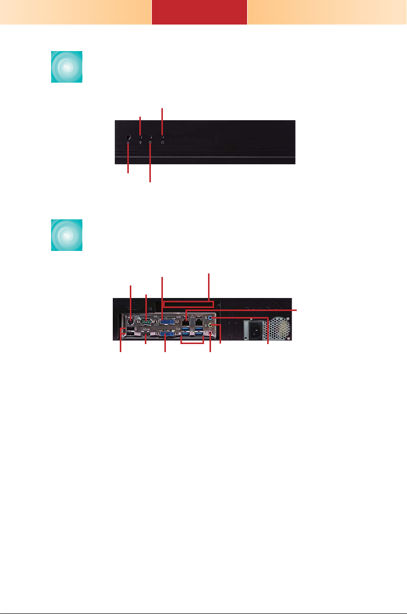
Front View
Reset Button
Power LED
Power Button
HDD LED
Rear View
DVI-I
PS/2 Mouse/KB
USB 2.0
(DVI-D signal)
COM 1
HDMI
DVI-I
Expansion slot
USB 3.0
Line-out
Mic-in/Center+Subwoofer
LAN 1-2
Line-in/Surround
2
Page 3
Key Features
PROCESSOR
CHIPSET
LAN
COM
DISPLAYS
USB
AUDIO
DT122-CR
3rd/2nd Generation Intel® CoreTM processors
Intel® QM77
2 LAN ports
1 COM port
2 DVI-I (1 DVI-D Signal), 1 HDMI
4 Type A USB 3.0/2.0/1.1 ports
2 Type A USB 2.0/1.1 ports
2 Type A USB 2.0/1.1 ports (optional)
Mic-in/Center+Subwoofer, Line-in/Surround, Line-out
3
Page 4
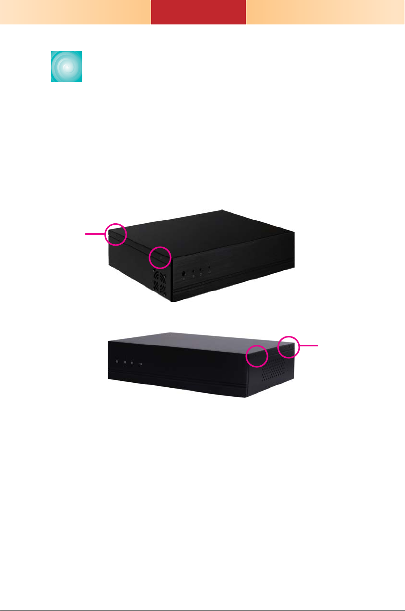
Removing the Chassis Cover
1. Make sure the system and all other peripheral devices
connected to it has been powered-off.
2. Disconnect all power cords and cables.
3. The 4 mounting screws on the sides of the system are
used to secure the cover to the chassis. Remove these
screws and then put them in a safe place for later use.
Mounting
screw
Mounting
screw
4
Page 5
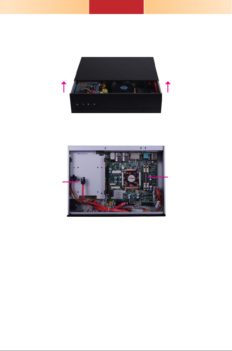
4. After removing the mounting screws, slide the cover
backwards.
Slide the Cover Backward
5. The DIMM sockets and SATA drive bay are readily
accessible after removing the chassis cover.
2.5"/3.5" SATA
drive bay
SODIMM socket
5
Page 6
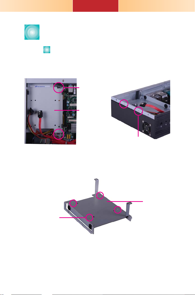
Installing a 2.5" or 3.5" SATA
Drive
lnstalling a 2.5" SATA Drive
1. Remove the 4 mounting screws that secure the drive
bay to the system.
2. Turn to the other side of the drive bay and remove the
4 mounting screws that secure the HDD brackets to
the drive bay.
Mounting screw
Drive bay
Mounting screw
Mounting screw
Drive bay
6
Page 7

3. Align the mounting holes of the SATA drive with the
mounting holes on the HDD bracket and then use the
provided mounting screws to secure the drive in place.
Mounting screw
Mounting screw
HDD bracket
SATA drive
7
Page 8

4. Turn to the other side of the drive bay. Use the
provided mounting screws from step 2 to secure the
SATA drive bay assembly onto the drive bay.
Drive bay
Mounting screw
Mounting screw
5. Place the SATA drive bay assembly into the chassis.
Secure the SATA drive bay with the mounting screws
you removed in step 1.
Mounting screw
8
Mounting screw
Page 9

6. Connect the SATA data cable and SATA power cable to
the connectors on the SATA drive.
SATA power
cable
SATA data cable
9
Page 10

lnstalling a 3.5" SATA Drive
1. Remove the 4 mounting screws that secure the drive
bay to the system.
Mounting screw
Drive bay
Mounting screw
2. Insert the spacer into the anti-shock bumper. You will
fi nd the spacers in the HDD drive bay kit that comes
with the DT122 package.
spacer
spacer
Drive bay
3. Place the SATA drive on the drive bay. Align the
mounting holes of the SATA drive with the mounting
holes on the drive bay.
SATA drive
Drive bay
10
Page 11

4. Use the provided mounting screws to secure the SATA
drive onto the drive bay.
Mounting screw
Mounting screw
Drive bay
5. Place the drive bay into the chassis. Secure the drive
bay with the mounting screws you removed in step 1.
Mounting screw
Mounting screw
6. Connect the SATA data cable and SATA power cable to
the connectors on the SATA drive.
SATA data cable
SATA power cable
11
Page 12

Installing the PCI or PCIe x16
Expansion Card
Important:
When inserting the riser
card, please select a
card within 175mm (as
shown on the next
picture).
1.
The PCIe x16 slot on the motherboard is used to in-
sert a TS200-1P and TS200-1E riser card.
To install the expansion card, you need to remove the
mounting bracket and the mounting screw that secure
the bracket to the chassis and then remove the brack-
. Put the screw and the brackets in a safe place for
et
later use.
Mounting screw
Mounting bracket
12
Page 13

T200-1P
T200-1E
Bracket
Mounting bracket and
mounting screw
PCI slot
PCIe x16 slot
13
Page 14

2. Insert the Expansion card with a bracket into the PCI
or PCIe x16 slot that is on the riser card. Replace the
screw you removed in step 1 to secure the bracket in
place.
Bracket
Mounting bracket
PCI
Expansion card
Rear view
and mounting
screw
Note:
The Expansion card used in the above illustrations may not resemble the
actual cards. These illustrations are for reference only.
14
Page 15

Mounting Options
Wall mount
There are 2 types of wall mount brackets:
• Type A
• Type B
Type A wall mount kit include:
• 2 type A wall mount brackets
1. If the mounting screw has been previously attached to
the top cover of the system, please remove them fi rst.
Mounting screw
Mounting screw
15
Page 16

2. At the sides of the system, use the mounting screws
removed in step 1 to secure the wall mount brackets
on each side of the system.
Wall mount bracket
Wall mount bracket
Mounting screw
160.00 28.60
80.00
120.00
319.00
16 2
180.00
16
2
Ø5.00
Ø3.60
4-#6-32
Ø4.00
Ø8.50
300.00
74.00
78.00
4.00
16
Page 17

Type B wall mount kit include:
• 2 type B wall mount brackets
• Bracket screws
1. The 4 mounting holes on the sides of the system are
used to mount the type B wall mount bracket.
2. Use the provided mounting screws to secure the type
B wall mount brackets on each side of the system.
Wall mount bracket
Wall mount bracket
17
Page 18

5.00
Ø8.50
5.00
16
R2.50
55.00
R2.50
40.00
300.00
335.00
360.00
37
4.00
40.00
55.00
78.00
18
Page 19

Board Layout and Jumper Settings
COM1 RS232/Power
select (JP1)
USB 2.0
PS/2
Mouse/KB
USB 8
USB 9
DVI-I
DVI-I
USB3.0 (0-1)
USB3.0 (2-3)
Line-in/ Surround
Line-out
Mic-in/ Center+Subwoofer
JP1
2
1
USB 8-9 power
select ( )JP8
COM 1
HDMI
(Top: DVI-D signal only)
LAN 1
LAN 2
10
9
1
2
PCIe x1 PCIe x1
Clear CMOS JP10
Normal (default) 1-2 On
Clear CMOS 2-3 On
USB Power: 0-1/2-3 (JP6)/ 8-9 (JP8)
+5V (default) 1-2 On
+5V_standby 2-3 On
PS/2 Power Select JP2
+5V (default) 1-2 On
+5V_standby 2-3 On
COM 1 (JP1), COM 2 (JP3) RS232/Power
RS232 (default) 1-3, 2-4 On
RS232 with power 3-5 (+5V),
Backlight Level Select JP11
+5V (default) 1-2 On
+3V3 2-3 On
1
6
5
1
Front audio
1
Chassis
1
intrusion
1
PS/2 power
select (JP2)
6
COM1 RS232/422/485
2
select ( )JP4
5
1
1
CPU fan
USB 0-1/ 2-3 power
select (JP6)
S/PDIF
4-6 (+12V) On
1
Power-on
select ( )JP7
COM2 RS232/Power
select (JP3)
ATX Powe r
2
1
SPI Flash BIOS
QM77
Panel power
select ( )JP9
1
5
6
2
6
5
Intel
2
6
9
COM2
1
2
5
COM2 RS232/
422/485 Select
1
(JP5)
SATA 3.0
Power LED
Clear CMOS
Standby
9
1
2
2
COM6
COM5
DDR3_2 SODIMM
DDR3_1 SODIMM
Socket G2
rPGA 988B
Mini PCIe
LCD/Inverter
PCIe x16
999
1
1
1
2
2
COM4
COM3
LVDS LCD
panel
Backlight
level (JP11)
power
1
1
1
13
21
40 39
COM 1 (JP4), COM 2 (JP5) RS232/RS422/RS485 Select
RS232 (default) 1-2 On
RS422 Full Duplex 3-4 On
RS485 5-6 On
Power-on Select JP7
Power-on via power button (default) 1-2 On
Auto Power-on 2-3 On
Panel Power Select JP9
+12V 1-2 On
+5V 3-4 On
+3.3V (default) 5-6 On
PCIe x16 Supported Confi gurations SW1
One PCIe x8, Two PCIe x4 1-2 On
Two PCIe x8 1 On, 2 Off
One PCIe x16 (default) 1-2 Off
934-DT1220-200G
19
Buzzer
System fan
1
SW1
2
Battery
9
10
(JP10)
9
1
A26212342
12
24
ON
SATA 0
SATA 1
SATA 4
SATA 5
SATA 2.0
USB 6-7
USB 4-5
19
2
DIO
Front
panel
1
11
USB 2.0
1
1
1
1
1
1
1
2
1
2
 Loading...