

Page 1
DS910-CD Installation Guide
Package Contents
•
1 DS910-CD system unit
•
1 HDD drive bay kit
- 4 HDD screws
- 1 SATA data/power cable
•
2 Terminal blocks
•
1 60W power adapter
- AC input: 100-240V, 50-60Hz
- DC output: 12V, 5A max (60W max)
•
1 Quick Installation Guide
•
1 DVD disk includes:
- Drivers/ Manual
Optional Items
•
1 VESA mount kit
•
1 Wall mount kit
•
1 Power cord
Note:
The CD that came with the system contains an autorun screen to install drivers, utilities,
and software applications required to enhance the performance of the system and a user's
manual for your reference. Insert the CD into a CD-ROM drive. The autorun screen will
appear. If after inserting the CD, “Autorun” did not automatically start, please go directly to
the root directory of the CD and double-click “Setup”. Please install all required drivers.
DFI reserves the right to change the specications at any time prior to the product's release. For the latest revision and for a
more details of the installation process, please refer to the user's manual on the website.
www.d.com
1
Page 2
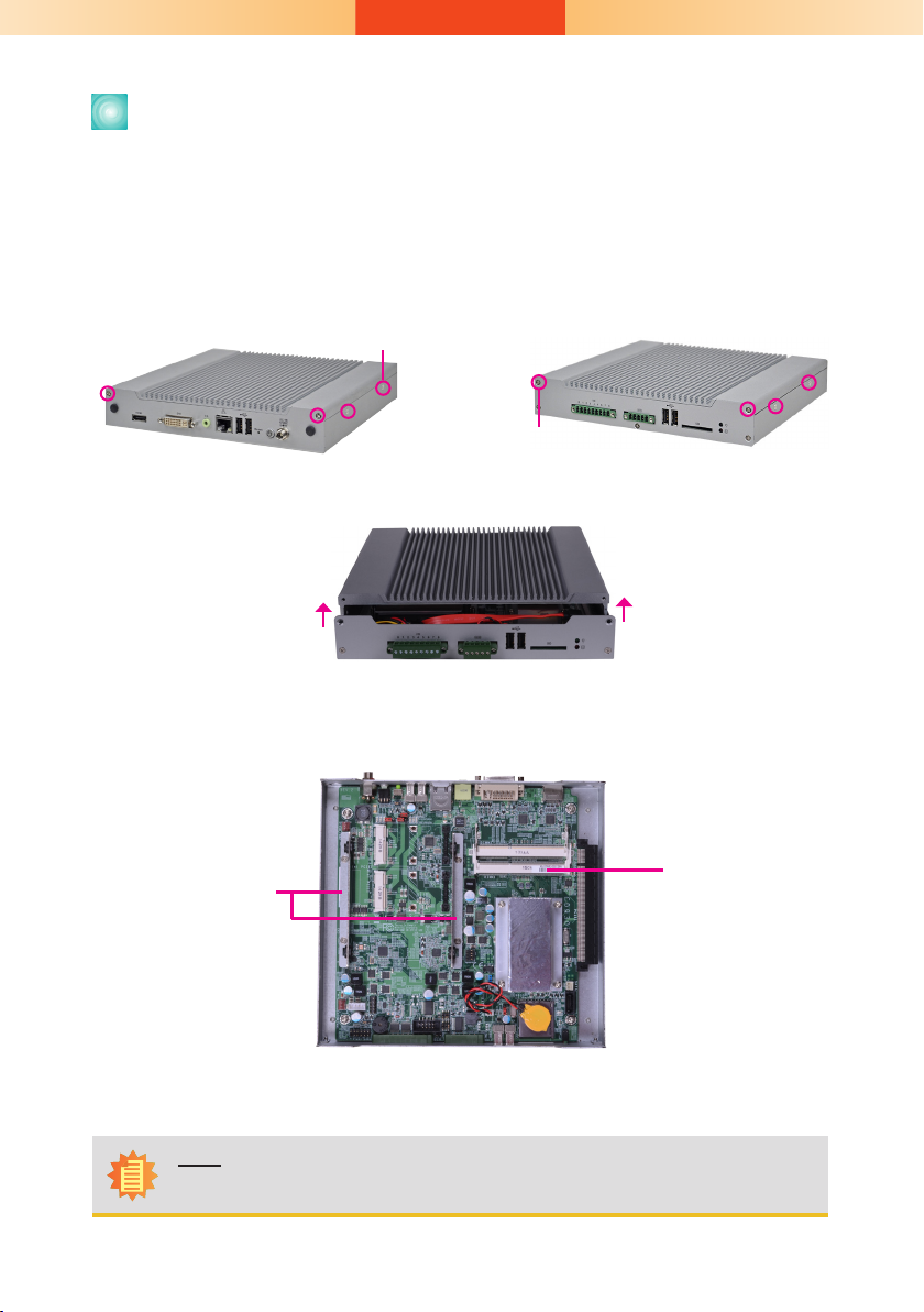
Removing the Chassis Cover
1. Make sure the system and all other peripheral devices connected to it has been poweredof f.
2. Disconnect all power cords and cables.
3. The 8 mounting screws on the sides of the system are used to secure the cover to the
chassis. Remove these screws and then put them in a safe place for later use.
Mounting screw
Mounting screw
4. After removing the mounting screws, lift the cover up.
Lift the Cover Upward
5. The SODIMM socket and SATA drive bay are readily accessible after removing the chassis cover.
SATA drive bay
Note:
The system comes with an aluminum sheet on the heat sink. Please do not tear off.
2
SODIMM socket
Page 3

Installing a SATA drive
1. Remove the 4 mounting screws that secure the HDD brackets to the drive bay.
Mounting screw
2. Align the mounting holes of the SATA drive with the mounting holes on the HDD bracket
and then use the provided mounting screws to secure the drive in place.
SATA drive
Mounting screw
HDD bracket
Mounting screw
3. Place the SATA drive (with HDD bracket)
into the chassis.
Replace the 4 mounting screws you re-
moved in step 1.
Mounting
screw
4. Connect the SATA data cable and SATA power cable to the connectors on the SATA
drive.
SATA power cable
SATA data cable
SATA power
connector
SATA power/
data connector
SATA data
connector
3
SATA power/data
connector
Page 4

Board Layout and Jumper Settings
Reset
USB 0
DC IN
USB 0/ USB 1
Power Select
(JP3)
1
System
fan 2
Mini PCIe 2
Power Select
(JP7)
Mini PCIe 2
Power
1
Reset/ Power
Select (JP11)
1
1
1
USB 1
Mini PCIe 1
Power Select (JP5)
Realtek
RTL8111DL
LAN
Line-out
ALC262
DVI-I
ASMEDIA
ASM1442
DDR3_1 SODIMM 1
DDR3_2 SODIMM 2
HDMI
ASMEDIA
ASM1442
Mini PCIe 1
System
Factory Testing
fan 1
1
1
HDD Power
Power-on
Select (JP1)
Mini PCIe Power: Mini PCIe 1 (JP5),
9
10
1
2
1
1
Mini PCIe 2 (JP7)
COM 1
DIO
COM 1 RS232/
Power Select (JP9)
COM 1 RS232/422/485
Select (JP8)
9
1
2
9
Chassis Intrusion
+3V (default) 1-2 On
+3V_standby 2-3 On
Clear CMOS Data JP2
Normal (default) 1-2 On
Clear CMOS Data 2-3 On
Power/Reset Select JP11
Reset (default) 1-2 On
Power 2-3 On
Note: The Power/Reset Select is used to select
the function of the reset bottom.
RS232/Power: COM 1 (JP9)
RS232 (default) 1-3 (RI)
RS232 with power 3-5 (+5V)
2-4 (DCD) On
4-6 (+12V) On
Intel Atom
N2600/N2800/D2550
mSATA/ Mini PCIe 1
5 1
6 2
5 1
6 2
1
Select (JP6)
D
C
B
A
3
1
Clear CMOS (JP2)
Battery
BIOS
1
5
SPI Flash
1
COM 2
1
USB 2/ USB 3
Power Select
(JP4)
USB 2
1
USB 3
Intel NM10
SDIO
USB Power: 0/1 (JP3), 2/3 (JP4)
+5V (default) 1-2 On
+5V_standby 2-3 On
Power-on Select JP1
Power-on via power button (default) 1-2 On
Power-on via AC power 2-3 On
mSATA/ Mini PCIe 1
Select (JP6)
Mini PCIe 1 mSATA
A 1-2 On 2-3 On
B 1-2 On 2-3 On
C 1-2 On 2-3 On
D 1-2 On 2-3 On
RS232/RS422/RS485 Select: COM 1 (JP8)
RS232 (default) 1-2 On
RS422 Full Duplex 3-4 On
RS485 5-6 On
4
PCIe x16
1
SATA
LED
934-DS910D-0A0G
A21432420
 Loading...