

Page 1

935-BP4331-004G
12000942A-DVD
System Board
User’s Manual
Page 2

Copyright
This publication contains information that is protected by copyright. No part of it
may be reproduced in any form or by any means or used to make any transformation/adaptation without the prior written permission from the copyright holders.
This publication is provided for informational purposes only. The manufacturer
makes no representations or warranties with respect to the contents or use
of this manual and specifi cally disclaims any express or implied warranties of
merchantability or fi tness for any particular purpose. The user will assume the
entire risk of the use or the results of the use of this document. Further, the
manufacturer reserves the right to revise this publication and make changes to
its contents at any time, without obligation to notify any person or entity of such
revisions or changes.
© 2009. All Rights Reserved.
Trademarks
Windows® 2000 and Windows® XP are registered trademarks of Microsoft Corporation. Award is a registered trademark of Award Software, Inc. Other trademarks
and registered trademarks of products appearing in this manual are the properties of their respective holders.
FCC and DOC Statement on Class B
This equipment has been tested and found to comply with the limits for a Class B
digital device, pursuant to Part 15 of the FCC rules. These limits are designed to
provide reasonable protection against harmful interference when the equipment
is operated in a residential installation. This equipment generates, uses and can
radiate radio frequency energy and, if not installed and used in accordance with
the instruction manual, may cause harmful interference to radio communications.
However, there is no guarantee that interference will not occur in a particular
installation. If this equipment does cause harmful interference to radio or television reception, which can be determined by turning the equipment off and on,
the user is encouraged to try to correct the interference by one or more of the
following measures:
• Reorient or relocate the receiving antenna.
• Increase the separation between the equipment and the receiver.
• Connect the equipment into an outlet on a circuit different from that to which
the receiver is connected.
• Consult the dealer or an experienced radio TV technician for help.
Notice:
1. The changes or modifi cations not expressly approved by the party responsible
for compliance could void the user’s authority to operate the equipment.
2. Shielded interface cables must be used in order to comply with the emission
limits.
Page 3

Table of Contents
About this Manual................................................................................
Warranty.................................................................................................
Static Electricity Precaution................................................................
Safety Measures.....................................................................................
About the Package...............................................................................
About the Genie BIOS Guideline.....................................................
Before Using the System Board.........................................................
System Board Layout............................................................................
English.....................................................................................................
简体中文..................................................................................................
繁體中文...................................................................................................
日本語...................................................................................................
한국어 ....................................................................................................
Debug LED POST and Troubleshooting..........................................
4
4
5
5
6
6
6
7
8
27
47
68
92
114
Page 4

4
E
English
Warranty
1. Warranty does not cover damages or failures that arised from misuse of the
product, inability to use the product, unauthorized replacement or alteration
of components and product specifi cations.
2. The warranty is void if the product has been subjected to physical abuse,
improper installation, modifi cation, accidents or unauthorized repair of the
product.
3. Unless otherwise instructed in this user’s manual, the user may not, under
any circumstances, attempt to perform service, adjustments or repairs on the
product, whether in or out of warranty. It must be returned to the purchase
point, factory or authorized service agency for all such work.
4. We will not be liable for any indirect, special, incidental or consequencial
damages to the product that has been modifi ed or altered.
Page 5
5
E
English
Static Electricity Precautions
It is quite easy to inadvertently damage your PC, system board, components
or devices even before installing them in your system unit. Static electrical discharge can damage computer components without causing any signs of physical
damage. You must take extra care in handling them to ensure against electrostatic build-up.
1. To prevent electrostatic build-up, leave the system board in its anti-static bag
until you are ready to install it.
2. Wear an antistatic wrist strap.
3. Do all preparation work on a static-free surface.
4. Hold the device only by its edges. Be careful not to touch any of the components, contacts or connections.
5. Avoid touching the pins or contacts on all modules and connectors. Hold
modules or connectors by their ends.
Important:
Electrostatic discharge (ESD) can damage your processor, disk drive and
other components. Perform the upgrade instruction procedures described
at an ESD workstation only. If such a station is not available, you can
provide some ESD protection by wearing an antistatic wrist strap and
attaching it to a metal part of the system chassis. If a wrist strap is
unavailable, establish and maintain contact with the system chassis
throughout any procedures requiring ESD protection.
Safety Measures
To avoid damage to the system:
• Use the correct AC input voltage range.
To reduce the risk of electric shock:
• Unplug the power cord before removing the system chassis cover for installation or servicing. After installation or servicing, cover the system chassis
before plugging the power cord.
Battery:
• Danger of explosion if battery incorrectly replaced.
• Replace only with the same or equivalent type recommend by the manufacturer.
• Dispose of used batteries according to local ordinance.
Page 6

6
E
English
About the Package
The system board package contains the following items. If any of these items are
missing or damaged, please contact your dealer or sales representative for assistance.
; One system board
; One IDE cable
; Two Serial ATA data cables
; Two Serial ATA power cables
; One I/O shield
; One DVD
; One user’s manual
The system board and accessories in the package may not come similar to the
information listed above. This may differ in accordance to the sales region or
models in which it was sold. For more information about the standard package in
your region, please contact your dealer or sales representative.
About the Genie BIOS Guideline
Genie BIOS allows confi guring the system to optimize system performance and
overclock capability. For detailed information about Genie BIOS, please download
the Genie BIOS Guideline from DFI’s website (www.dfi .com). The guideline is also
available in the provided DVD.
Before Using the System Board
Before using the system board, prepare basic system components.
If you are installing the system board in a new system, you will need at least the
following internal components.
• A CPU
• Memory module
• Storage devices such as hard disk drive, CD-ROM, etc.
You will also need external system peripherals you intend to use which will normally include at least a keyboard, a mouse and a video display monitor.
Page 7
7
E
English
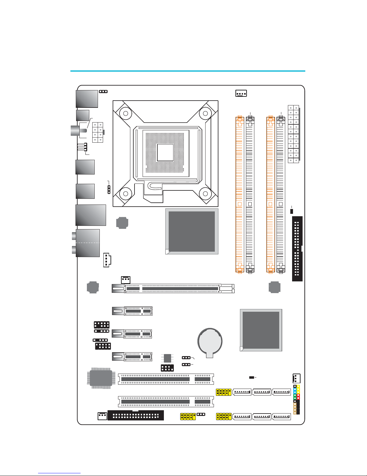
System Board Layout
Mouse
KB
USB 9
USB 8
CD-in
Optical
S/PDIF-out
1
1
Coaxial RCA
S/PDIF-out
1
USB 11
USB 10
LAN
USB 7
USB 6
1
JMC250
COM
Front audio
1
USB 0-1
ITE
IT8718F
System
fan
1
1
Front
panel
FDD
1
1
1
1
USB 2-3
USB 4-5
1
Chassis
fan
Battery
IDE
1
13
2412
ATX
power
1
1
CPU fan
DDR3-1
DDR3-2
DDR3-3
DDR3-4
DRAM
Power LED
1
NB fan
SPI Flash
BIOS
1
2
7
8
Download
BIOSFlash
Intel
ICH10
IrDA
1
12V power
PS/2 power
select (JP7)
1
Intel
P43
Standby
Power LED
1
11
1
11
Clear CMOS (JP2)
USB 0-5
PCI 1
PCI 2
PCIE 4
PCIE 2
PCIE 1
SATA 4 SATA 2 SATA 0
SATA 1SATA 3SATA 5
USB 6-11 power
select (JP5)
C217
PCIE 3
Clear CMOS
(JP8)
Socket 775
JMicron
JMB368
Realtek
ALC885
1
(JP6)
Secondary RTC reset (JP12)
1
S/PDIF
1
2
9
10
2
9
10
2
33
34
power select
2910
129
10
129
10
2
19 20
2
39
40
Line-in
Front R/L
Mic-in
Center/
Subwoofer
Side R/L
Rear R/L
Page 8

8
English
E
English
Chapter 1 - Introduction
Specifications
Processor
Chipset
System Memory
Expansion Slots
BIOS
Audio
LAN
Serial ATA
IDE
• LGA 775 socket for:
- Intel
®
CoreTM2 Quad and Intel® CoreTM2 Duo
• Supports Intel Enhanced Memory 64 Technology (EMT64T)
• Supports Enhanced Intel SpeedStep Technology (EIST)
• Supports Intel Hyper-Threading Technology
• Supports 1333/1066/800MHz FSB
• Intel
®
chipset
- Northbridge:
Intel
®
P43 Express chipset
Intel
®
Fast Memory Access technology
- Southbridge:
Intel
®
ICH10
• Four 240-pin DDR3 DIMM sockets
• Supports DDR3 1333(O.C.)/1066/800 MHz
• Supports up to 8GB system memory
• Delivers up to 21Gb/s bandwidth at 1333MHz
• Supports dual channel (128-bit wide) memory interface
• Supports x8/x16 non-ECC unbuffered DIMMs
• 1 PCI Express (Gen 2) x16 slot
• 3 PCI Express x1 slots
• 2 PCI slots
• Award BIOS
• 8Mbit SPI fl ash BIOS
• CMOS Reloaded
• Realtek ALC885 High Defi nition audio CODEC
• 8-channel audio output
• DAC SNR/ADC SNR of 106dB/101dB
• Full-rate lossless content protection technology
• Optical S/PDIF-out and coaxial RCA S/PDIF-out interfaces
• JMC250 PCIE Gigabit LAN controller
• Fully compliant to IEEE 802.3 (10BASE-T), 802.3u
(100BASE-TX) and 802.3ab (1000BASE-T) standards
• Supports up to 6 SATA devices
• SATA speed up to 3Gb/s
• JMicron JMB368 PCI Express to PATA host controller
• Supports up to 2 UltraDMA 100Mbps IDE devices
Page 9
9
English
E
English
Rear Panel I/O
Internal I/O
Power
Management
Hardware
Monitor
PCB
• 1 mini-DIN-6 PS/2 mouse port
• 1 mini-DIN-6 PS/2 keyboard port
• 1 optical S/PDIF-out port
• 1 coaxial RCA S/PDIF-out port
• 1 Clear CMOS jumper
• 6 USB 2.0/1.1 ports
• 1 RJ45 LAN port
• Center/subwoofer, rear R/L and side R/L jacks
• Line-in, line-out (front R/L) and mic-in jacks
• 3 connectors for 6 additional external USB 2.0 ports
• 1 connector for an external COM port
• 1 front audio connector
• 1 S/PDIF connector
• 1 CD-in connector
• 1 IrDA connector
• 6 Serial ATA connectors
• 1 40-pin IDE connector
• 1 fl oppy connector
• 1 24-pin ATX power connector
• 1 8-pin 12V power connector
• 1 front panel connector
• 4 fan connectors
• 1 download fl ash BIOS connector
• ACPI and OS Directed Power Management
• ACPI STR (Suspend to RAM) function
• Wake-On-PS/2 Keyboard/Mouse
• Wake-On-USB Keyboard
• Wake-On-LAN
• RTC timer to power-on the system
• AC power failure recovery
• Monitors CPU/Chipset/PWM temperature and overheat
alarm
• Monitors CPU Core / DRAM / NB Core / CPU VTT / +3.3V /
+5.0V / +12V / 5V Standby voltages
• Monitors the speed of the cooling fans
• CPU Overheat Protection function monitors CPU temperature and fan during system boot-up - automatic shutdown
upon system overheat
• 4 layers, ATX form factor
• 20.5cm (8.07”) x 30.5cm (12”)
Page 10
10
English
E
English
C217
Chapter 2 - Hardware Installation
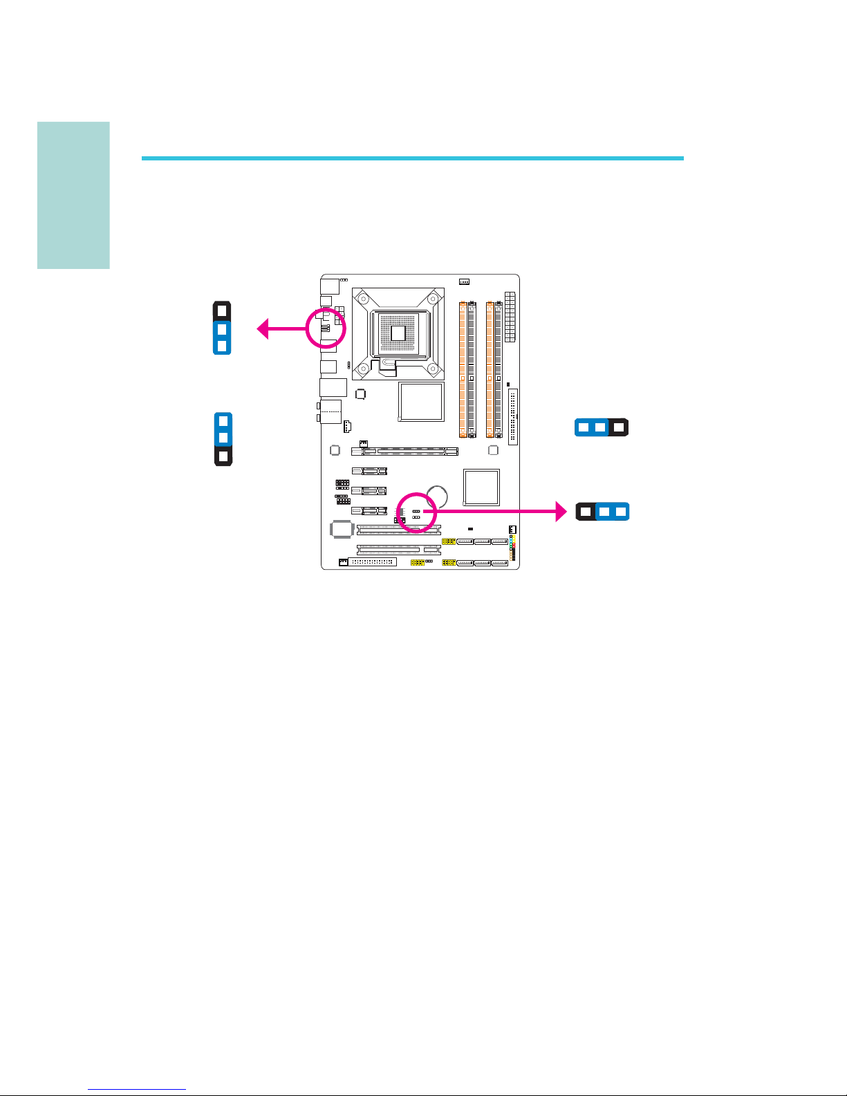
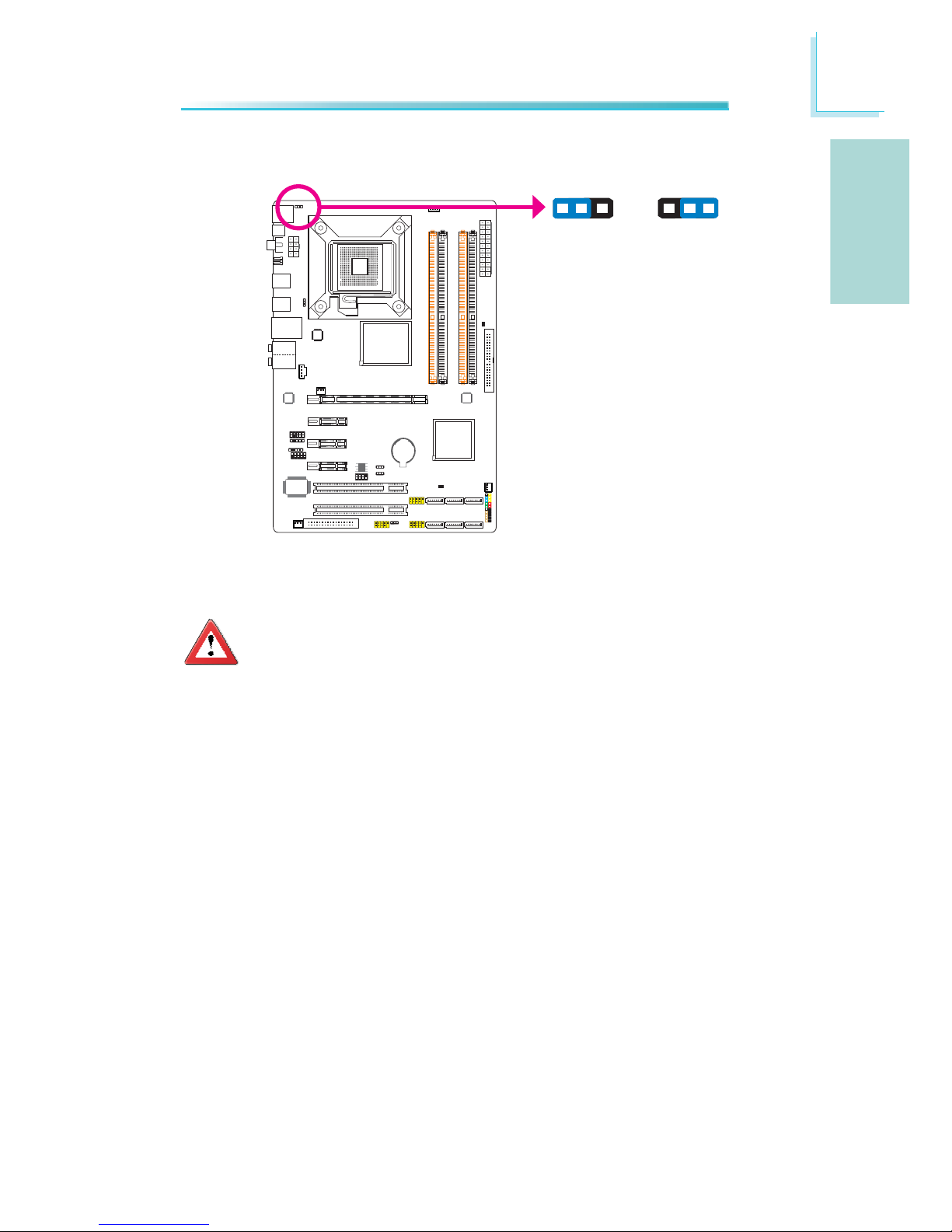
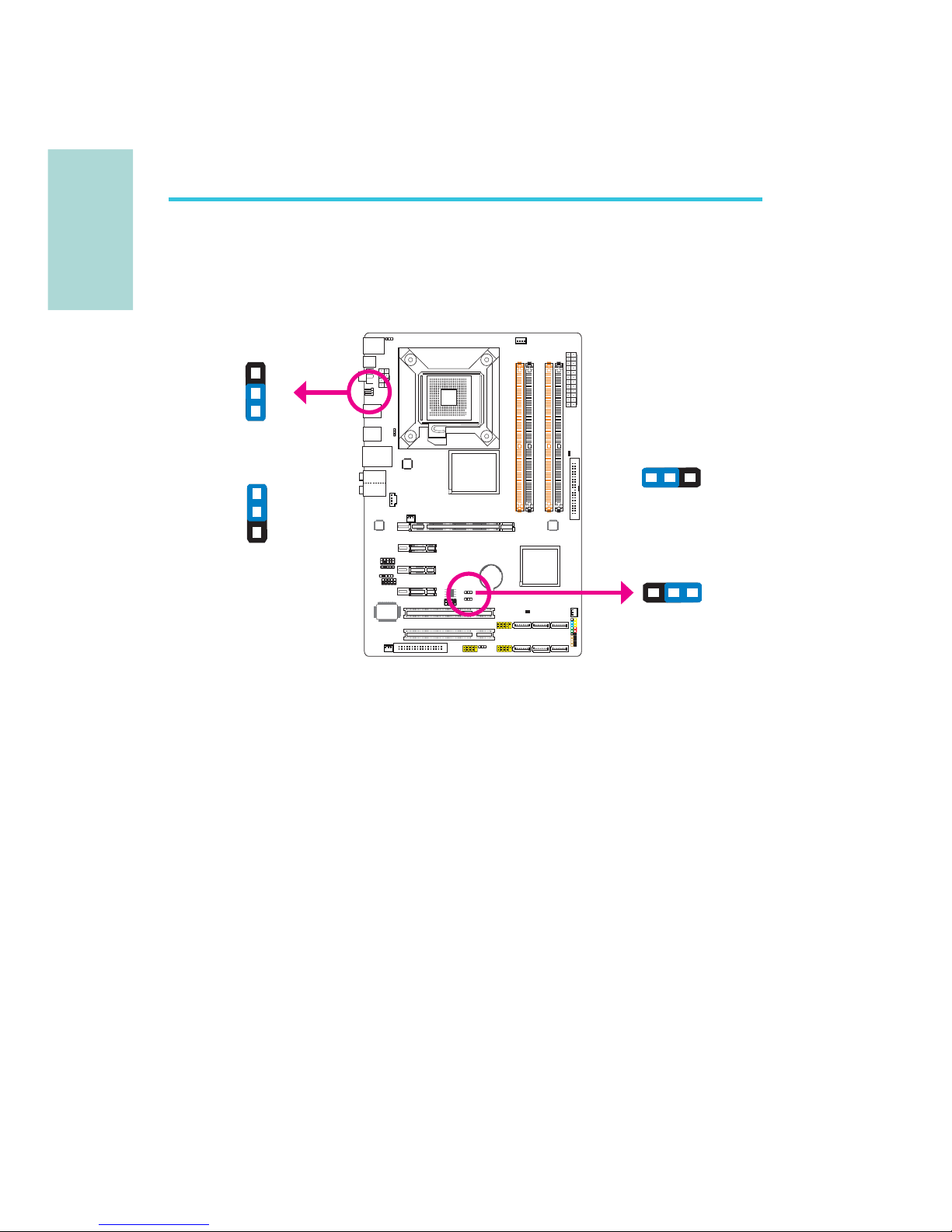
Jumper Settings
If you encounter the following,
a) CMOS data becomes corrupted.
b) You forgot the supervisor or user password.
c) The overclocked settings in the BIOS resulted to the system’s instability or
caused system boot up problems.
you can reconfi gure the system with the default values stored in the ROM BIOS.
JP8 is accessible from the rear panel of the system. This provides convenience by
allowing you to clear the CMOS without having to remove the chassis cover.
To load the default values stored in the ROM BIOS, please follow the steps below.
1. Power-off the system then unplug the power cord.
2. Set JP2/JP8 pins 2 and 3 to On. Wait for a few seconds and set JP2/JP8 back
to its default setting, pins 1 and 2 On.
3. Now plug the power cord then power-on the system.
Clear CMOS Data
2-3 On:
Clear CMOS Data
1-2 On: Normal
(default)
JP2
312
312
3
1
2
3
1
2
JP8
2-3 On:
Clear CMOS Data
1-2 On: Normal
(default)
Page 11
11
English
E
English
C217
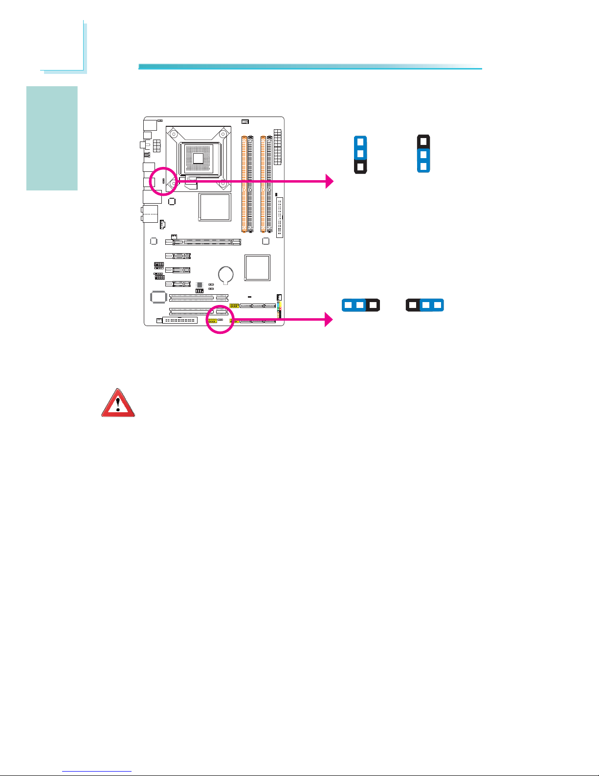
PS/2 Power Select
Selecting 5VSB will allow you to use the PS/2 keyboard or PS/2 mouse to wake
up the system.
Important:
The 5VSB power source of your power supply must support ≥720mA.
JP7
2-3 On: 5VSB1-2 On: 5V
(default)
312
312
Page 12
12
English
E
English
C217
C217
USB Power Select
USB 6-11
(JP5)
USB 0-5
(JP6)
Selecting 5VSB will allow you to use the USB keyboard or USB mouse to wake up
the system.
Important:
The 5VSB power source of your power supply must support ≥1.5A (2
devices) or ≥2A (3 or more devices).
2-3 On: 5VSB
1-2 On: 5V
(default)
312
312
1
3
2
1
3
2
1-2 On: 5V
(default)
2-3 On: 5VSB
Page 13
13
English
E
English
C217
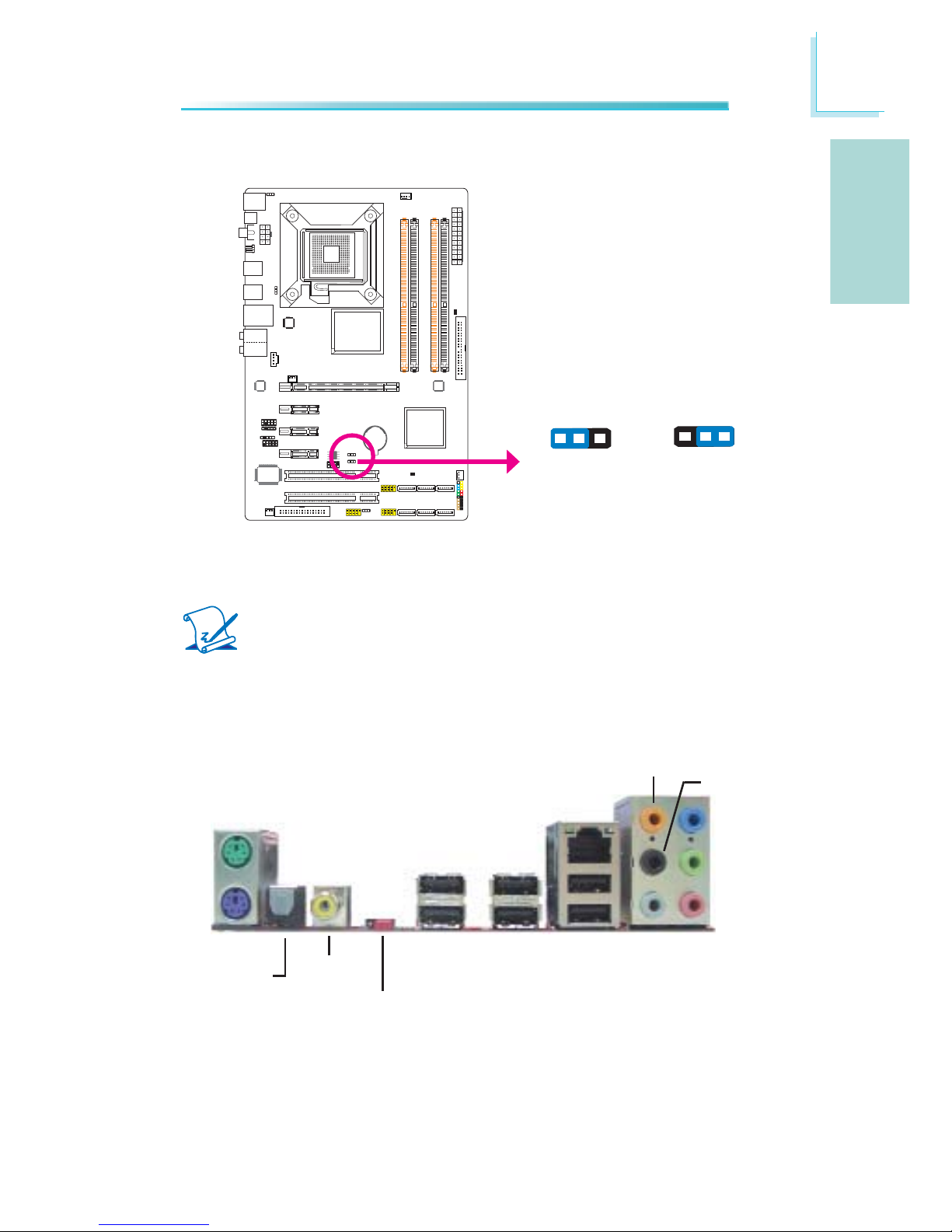
Secondary RTC Reset
When the RTC battery is removed, this jumper resets the manageability register
bits in the RTC.
Note:
1. The SRTCRST# input must always be high when all other RTC power
planes are on.
2. In the case where the RTC battery is dead or missing on the platform, the SRTCRST# pin must rise before the RSMRST# pin.
2-3 On:
RTC Reset
1-2 On: Normal
(default)
JP12
312
312
Rear Panel I/O Ports
PS/2 K/B
Optical
S/PDIF-out
USB 10 USB 6-7
Coaxial
S/PDIF-out
Mic-in
Side R/L
Center/Subwoofer
Rear R/L
Line-in
Front R/L
LAN
PS/2
Mouse
USB 11
USB 8
USB 9
Clear CMOS
jumper
Page 14

14
English
E
English
C217
PS/2 Mouse and PS/2 Keyboard Ports
These ports are used to connect a PS/2 mouse and a PS/2 keyboard.
Optical S/PDIF
The optical S/PDIF jack is used to connect an external audio output device using
an optical S/PDIF cable.
Coaxial RCA S/PDIF
The coaxial RCA S/PDIF jack is used to connect an external audio output device
using a coaxial S/PDIF cable.
Important:
DO NOT use optical S/PDIF and Coaxial RCA S/PDIF at the same time.
PS/2 Ports and S/PDIF Ports
PS/2 Mouse
PS/2 KB
Optical S/PDIF
Coaxial RCA
S/PDIF
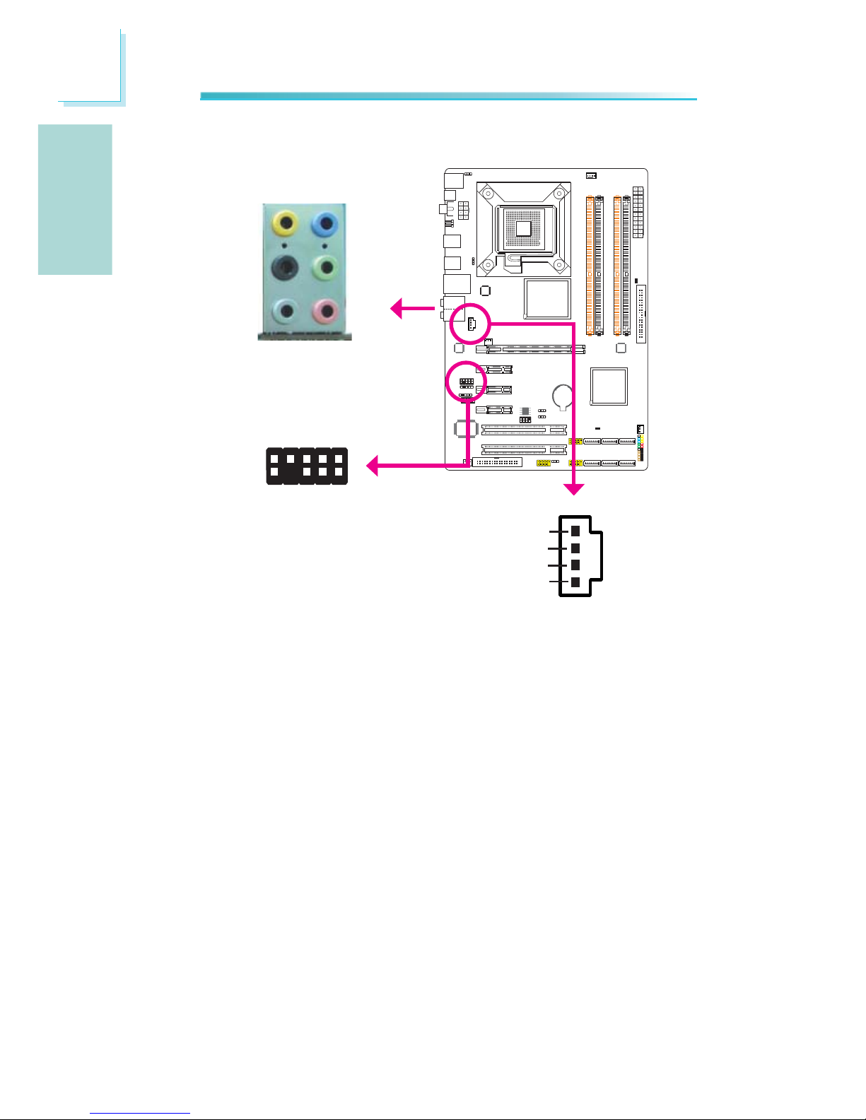
S/PDIF Connector
The S/PDIF connector is used to connect an external S/PDIF port. Your S/PDIF
port may be mounted on a card-edge bracket. Install the card-edge bracket to
an available slot at the rear of the system chassis then connect the audio cable
to the S/PDIF connector. Make sure pin 1 of the audio cable is aligned with pin 1
of the S/PDIF connector.
15
+5V
Key
SPDIF out
Ground
SPDIF in
S/PDIF
connector
Page 15
15
English
E
English
C217
USB 4-5
USB 0-1
USB 9
LAN
USB 8
USB 7
USB 6
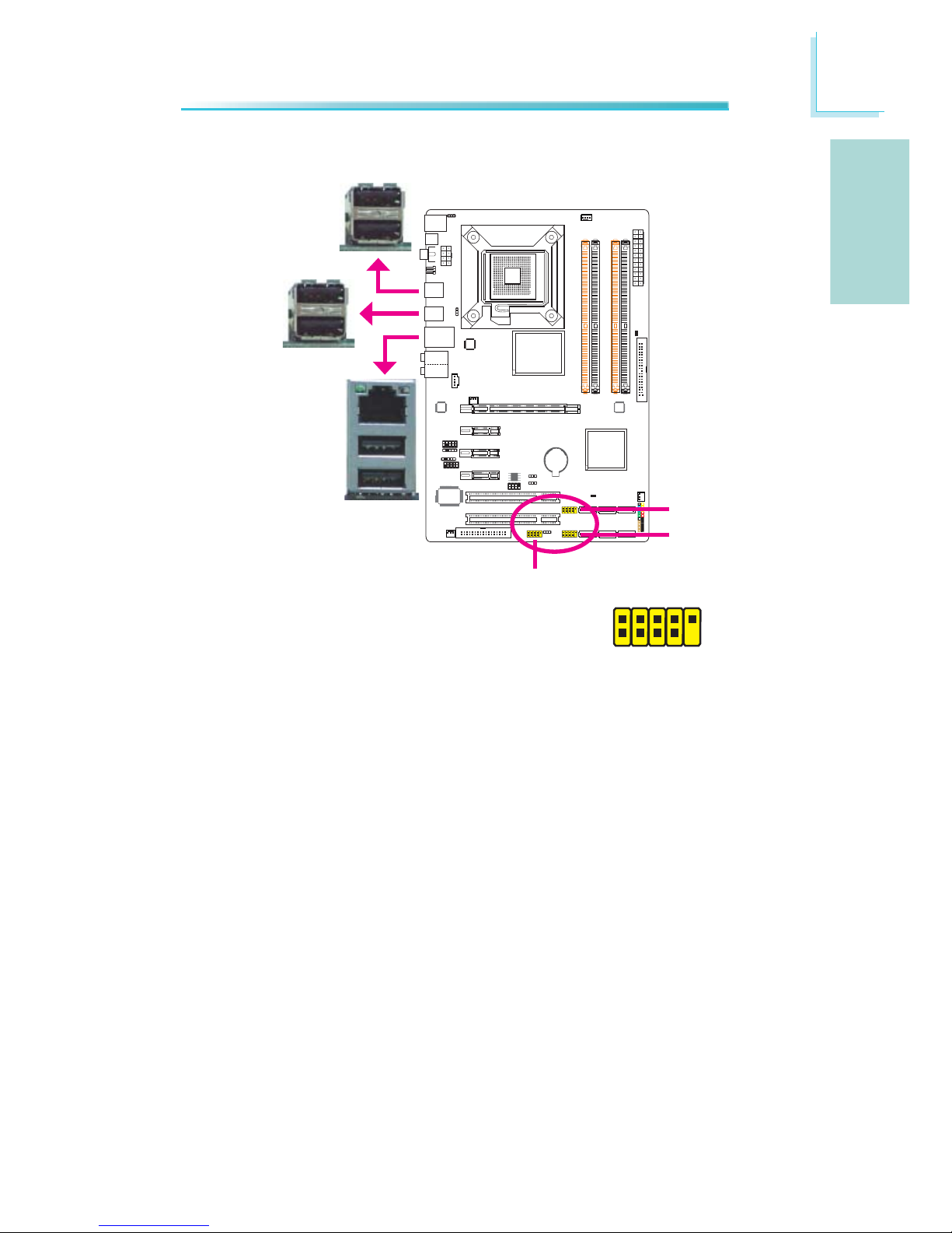
USB and LAN Ports
USB
The USB ports are used to connect USB 2.0/1.1 devices. The 10-pin connectors
allow you to connect 6 additional USB 2.0/1.1 ports. Your USB ports may come
mounted on a card-edge bracket. Install the card-edge bracket to an available
slot at the rear of the system chassis then connect the USB port cables to these
connectors.
LAN
The LAN port allows the system board to connect to a local area network by
means of a network hub.
USB 2-3
1
VCC
-Data
+Data
GND
Key
VCC
-Data
+Data
GND
N. C.
2
10
9
USB 11
USB 10
Page 16
16
English
E
English
C217
Rear Panel Audio
Center/Subwoofer Jack (Orange)•
This jack is used to connect to the center and subwoofer speakers of the au-
dio system.
Rear Right/Left Jack (Black)•
This jack is used to connect to the rear right and rear left speakers of the
audio system.
Side Right/Left Jack (Gray)•
This jack is used to connect to the side left and side right speakers of the
audio system.
Line-in (Light Blue)•
This jack is used to connect any audio devices such as Hi-fi set, CD player,
tape player, AM/FM radio tuner, synthesizer, etc.
Line-out - Front Right/Left Jack (Lime)•
This jack is used to connect to the front right and front left speakers of the
audio system.
Mic-in Jack (Pink)•
This jack is used to connect an external microphone.
Audio and CD-In
Rear audio
Front R/L
Line-in
Mic-in
Rear R/L
Center/
Subwoofer
Side R/L
CD-in
4
1
Left audio channel
Right audio channel
Ground
Ground
Front
audio
10
Mic
Mic Power
AuD_R_Out
N. C.
AuD_L_Out
GND
AuD_Vcc
Key
9
1
AuD_R_Return
AuD_L_Return
2
Page 17
17
English
E
English
C217
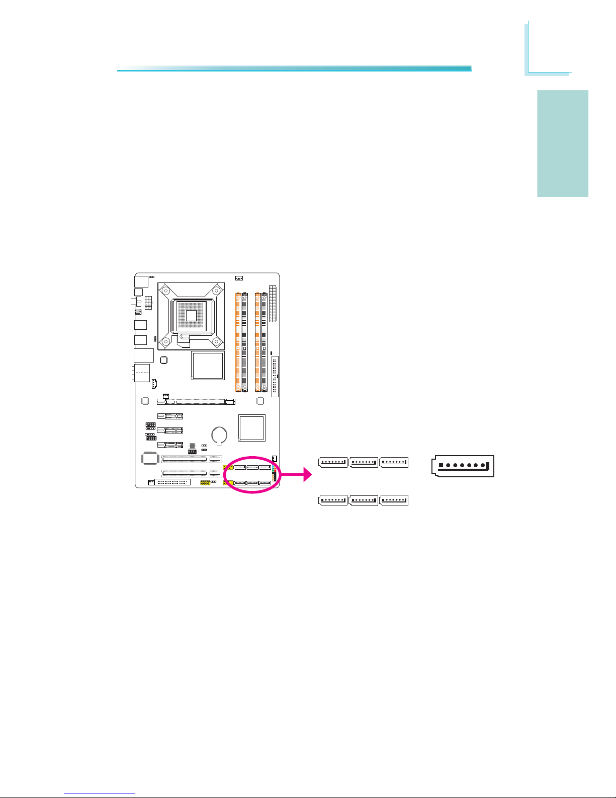
C217
The Serial ATA (SATA) connectors are used to connect Serial ATA drives. Connect
one end of the Serial ATA cable to a Serial ATA connector and the other end to
your Serial ATA device.
Serial ATA Connectors
Front Audio
The front audio connector is used to connect to the line-out and mic-in jacks that
are at the front panel of your system.
CD-in
The CD-in connector is used to receive audio from a CD-ROM drive, TV tuner or
MPEG card.
Internal I/O Connectors
SATA 5 S ATA 3 SATA 1
SATA 4 S ATA 2 SATA 0
1
RXN
GND
TXP
TXN
GND
7
RXP
GND
Page 18
18
English
E
English
C217
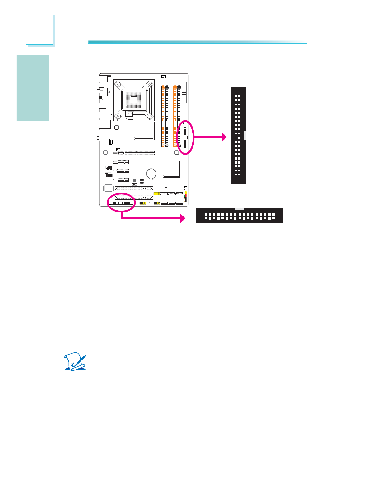
FDD Connector and IDE Connector
FDD Connector
The fl oppy disk drive connector is used to connect a fl oppy drive. Insert one end
of the fl oppy cable into this connector and the other end-most connector to the
fl oppy drive. The colored edge of the cable should align with pin 1 of this connector.
IDE Connector
The IDE disk drive connector is used to connect 2 IDE disk drives. An IDE cable
have 3 connectors on them, one that plugs into this connector and the other 2
connects to IDE devices. The connector at the end of the cable is for the Master
drive and the connector in the middle of the cable is for the Slave drive. The colored edge of the cable should align with pin 1 of this connector.
Note:
When using two IDE drives, one must be set as the master and the
other as the slave. Follow the instructions provided by the drive manufacturer for setting the jumpers and/or switches on the drives.
IDE
40 39
21
FDD
33
34
2
1
Page 19
19
English
E
English
C217
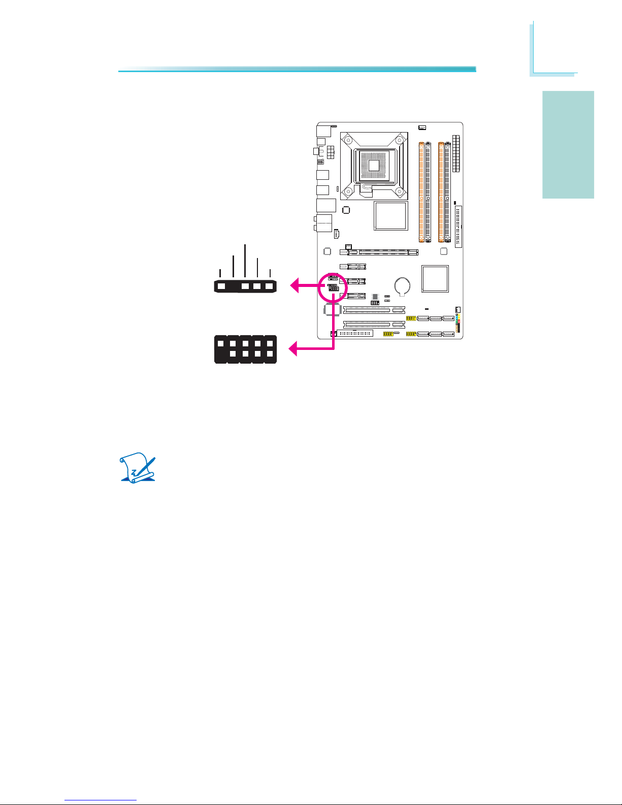
IrDA and COM (Serial) Connectors
IrDA
Connect the cable connector from your IrDA module to the IrDA connector.
Note:
The sequence of the pin functions on some IrDA cable may be reversed
from the pin function defi ned on the system board. Make sure to connect
the cable to the IrDA connector according to their pin functions.
You may need to install the proper drivers in your operating system to use the
IrDA function. Refer to your operating system’s manual or documentation for
more information.
COM (Serial)
The COM (Serial) connector is used to connect modems, serial printers, remote
display terminals, or other serial devices. Your COM port may come mounted on
a card-edge bracket. Install the card-edge bracket to an available slot at the rear
of the system chassis then connect the serial port cable to this connector. The
colored edge of the cable should align with pin 1 of this connector.
IrDA
15
VCC
N. C.
IRRX
Ground
IRTX
COM
1
2
9
DCD-
TD
GND
RTS-
RI-
RD
DTR-
DSR-
CTS-
Page 20
20
English
E
English
C217
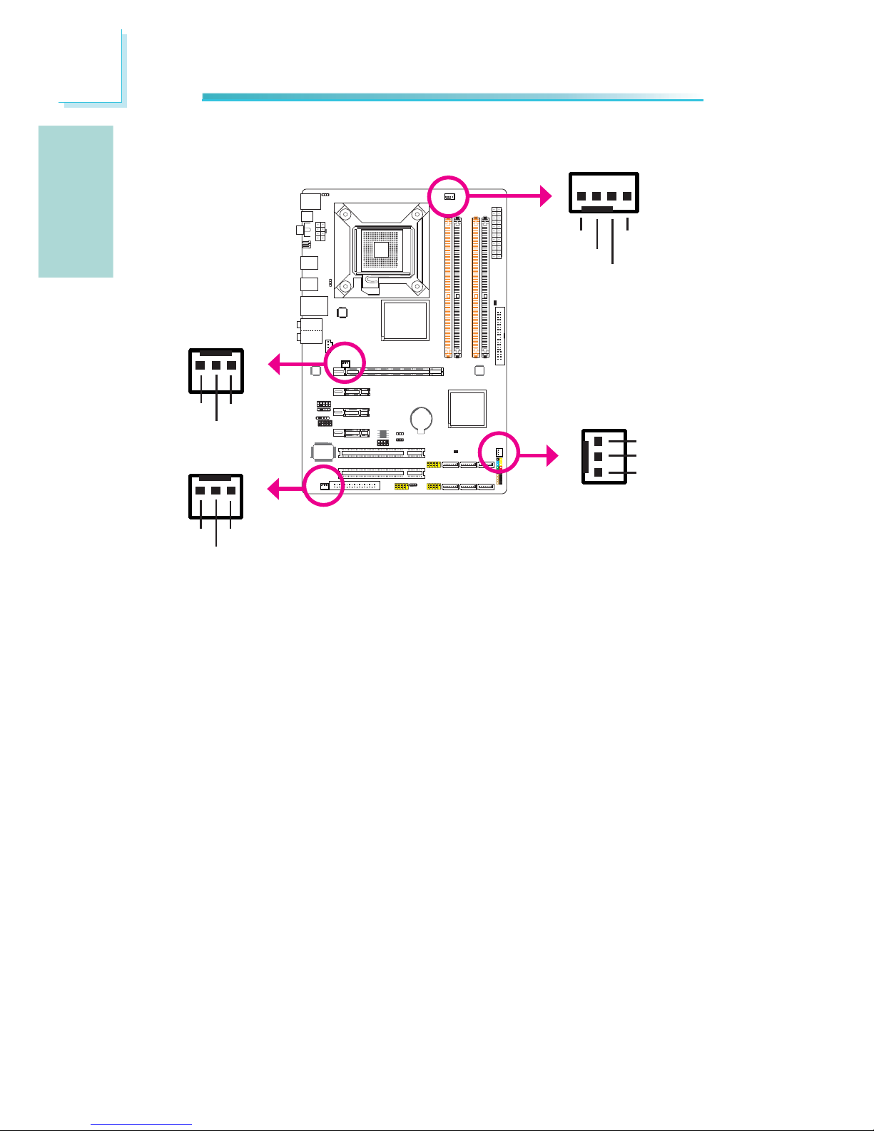
Cooling Fan Connectors
These fan connectors are used to connect cooling fans. Cooling fans will provide
adequate airfl ow throughout the chassis to prevent overheating the CPU and sys-
tem board components.
CPU fan
4
1
Sense
Power
Ground Speed
Control
13
Sense
Power
Ground
NB fan
System fan
1
3
Sense
Power
Ground
13
Sense
Power
Ground
Chassis fan
Page 21
21
English
E
English
C217
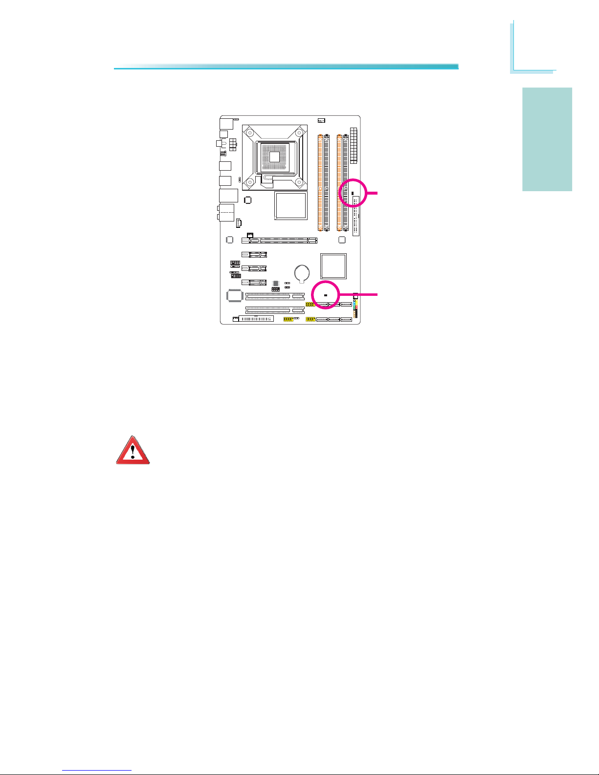
DRAM Power LED
Standby Power LED
LEDs
DRAM Power LED
This LED will light when the system’s power is on.
Standby Power LED
This LED will light when the system is in the standby mode.
Important:
When the DRAM Power LED and/or Standby Power LED lit red, it indicates that power is present on the DIMM sockets and/or PCI slots. Power-off the PC then unplug the power cord prior to installing any memory
modules or add-in cards. Failure to do so will cause severe damage to
the motherboard and components.
Page 22
22
English
E
English
C217
C217
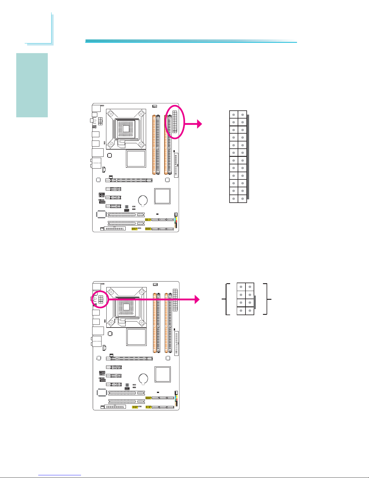
Power Connectors
Use a power supply that complies with the ATX12V Power Supply Design Guide
Version 1.1. An ATX12V power supply unit has a standard 24-pin ATX main power
connector that must be inserted into this connector.
Your power supply unit may come with an 8-pin or 4-pin +12V power connector.
The +12V power enables the delivery of more +12VDC current to the processor’s
Voltage Regulator Module (VRM). If available, it is preferable to use the 8-pin
power; otherwise connect a 4-pin power to this connector.
13
12 24
1
+3.3VDC
+3.3VDC
COM
+5VDC
COM
+5VDC
COM
PWR_OK
+5VSB
+12VDC
+12VDC
+3.3VDC
+3.3VDC
-12VDC
COM
PS_ON#
COM
COM
COM
NC
+5VDC
+5VDC
+5VDC
COM
+12V
Ground
8
5
4
1
Page 23
23
English
E
English
The power connectors from the power supply unit are designed to fi t the 24-pin
and 8-pin connectors in only one orientation. Make sure to fi nd the proper orien-
tation before plugging the connectors.
The system board requires a minimum of 300 Watt power supply to operate. Your
system confi guration (CPU power, amount of memory, add-in cards, peripherals,
etc.) may exceed the minimum power requirement. To ensure that adequate
power is provided, we strongly recommend that you use a minimum of 400 Watt
(or greater) power supply.
Important:
Insuffi cient power supplied to the system may result in instability or
the add-in boards and peripherals not functioning properly. Calculating
the system’s approximate power usage is important to ensure that the
power supply meets the system’s consumption requirements.
Restarting the PC
Normally, you can power-off the PC by:
1. Pressing the power button at the front panel of the chassis.
or
2. Pressing the power switch that is on the system board (note: not all system
boards come with this switch).
If for some reasons you need to totally cut off the power supplied to the PC,
switch off the power supply or unplug the power cord. Take note though that if
you intend to restart it at once, please strictly follow the steps below.
1. The time where power is totally discharged varies among power supplies. It’s
discharge time is highly dependent on the system’s confi guration such as the
wattage of the power supply, the sequence of the supplied power as well as
the number of peripheral devices connected to the system. Due to this reason, we strongly recommend that you wait for the Standby Power LED (refer
to the “LEDs” section in this chapter for the location of the Standby Power
LED) to lit off.
2. After the Standby Power LED has lit off, wait for 6 seconds before powering
on the PC.
If the system board is already enclosed in a chassis which apparently will not
make the Standby Power LED visible, wait for 15 seconds before you restore
power connections. 15 seconds is approximately the time that will take the
LED to lit off and the time needed before restoring power.
The above will ensure protection and prevent damage to the motherboard and
components.
Page 24
24
English
E
English
C217
C217
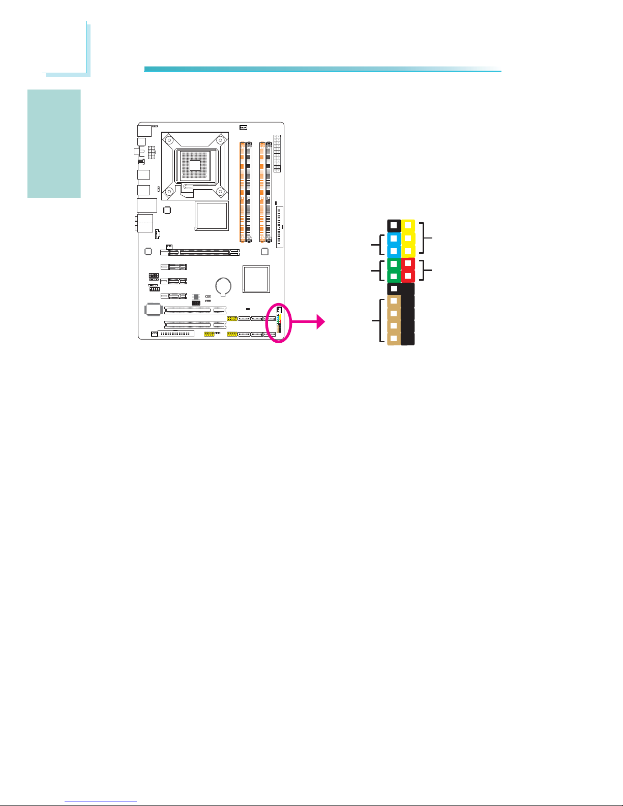
Front Panel Connectors
HD-LED: Primary/Secondary IDE LED
This LED will light when the hard drive is being accessed.
RESET: Reset Switch
This switch allows you to reboot without having to power off the system thus
prolonging the life of the power supply or system.
SPEAKER: Speaker Connector
This connects to the speaker installed in the system chassis.
ATX-SW: ATX Power Switch
Depending on the setting in the BIOS setup, this switch is a “dual function power
button” that will allow your system to enter the Soft-Off or Suspend mode.
12
19 20
PWR-LED
ATX- SW
SPEAKER
HD-LED
RESET
Page 25
25
English
E
English
PWR-LED: Power/Standby LED
When the system’s power is on, this LED will light. When the system is in the
S1 (POS - Power On Suspend) or S3 (STR - Suspend To RAM) state, it will blink
every second.
Note:
If a system did not boot-up and the Power/Standby LED did not light after it was powered-on, it may indicate that the CPU or memory module
was not installed properly. Please make sure they are properly inserted
into their corresponding socket.
HD-LED
(Primary/Secondary IDE LED)
Reserved
ATX-SW
(ATX power switch)
Reserved
RESET
(Reset switch)
SPEAKER
(Speaker connector)
PWR-LED
(Power/Standby LED)
Pin Assignment
HDD LED Power
HDD
N. C.
N. C.
PWRBT+
PWRBT-
N. C.
N. C.
Ground
H/W Reset
Speaker Data
N. C.
Ground
Speaker Power
LED Power (+)
LED Power (+)
LED Power (-) or Standby Signal
Pin
3
5
14
16
8
10
18
20
7
9
13
15
17
19
2
4
6
Page 26
26
English
E
English
C217
C217
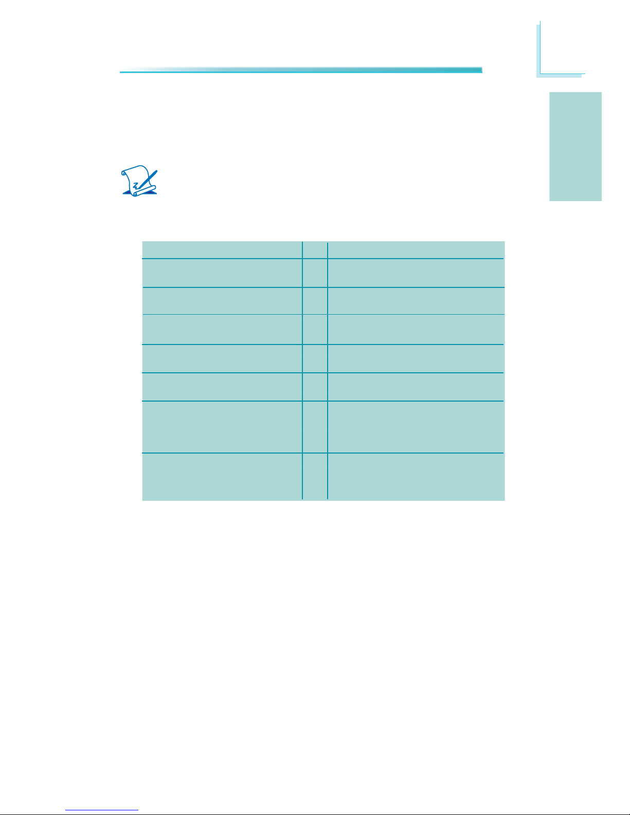
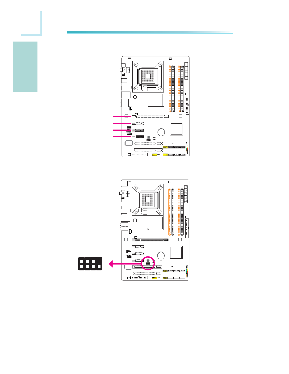
PCI Express Slots
PCI Express x16
Download Flash BIOS Connector
PCI Express x1
1
2
8
7
GROUND
SPI_CLK
SPI_MOSI
SPI_VCC3
SPI_CS0B
SPI_MIS0
SPI_HOLD#
PCI Express x1
PCI Express x1
Page 27
27
简体中文
简体中文
中央处理器
. 配置LGA 775CPU脚座,适用于以下处理器类
型:
Intel®Core.
TM
2 Quad(四核心处理器)与
Intel®CoreTM2 Duo
支持Intel EMT64T (64位英特尔内存扩展技.
术)
支持EIST(英特尔动态节能技术).
支持Intel超线程(HT)技术.
支持1333/1066/800MHz FSB.
芯片组
. Intel芯片组
北桥:-
Intel
®
P43高速芯片组
具备Intel®快速内存访问
南桥:Intel®ICH10-
系统内存
. 四组240-pin DDR3内存插槽
支持DDR3 1333(超频)/1066/800MHz内存.
使用1333MHz内存时,可支持高达21GB/s的内.
存带宽
支持双通道(128位)内存接口.
支持8GB系统内存容量 .
支持non-ECC x8/x16 unbuffered内存模块.
扩充插槽
. 一组PCI Express(GEN 2)X16插槽
三组PCI Express x1插槽.
两组PCI插槽.
BIOS
. 具备Award BIOS
具备8Mbit SPI Flash BIOS.
具备CMOS Reloaded.
音频
. Realtek ALC885八声道HD音频译码器
同轴RCA S/PDIF-out插口.
光纤S/PDIF-out接口 .
DAC SNR/ADC SNR比为106dB/101dB.
全速率内建无失真内容保护技术.
网络
. JMC250 PCIE Gigabit LAN控制器
完全兼容于IEEE 802.3(10BASE-T), 802.3u .
(100BASE-TX)与802.3ab(1000BASE-T)标准
第一章-规格
Page 28

28
简体中文
简体中文
SATA
. 支持六个SATA装置
SATA速度高达3Gb/s.
IDE
. JMicron JMB368 PCI Express芯片及PATA主控
制器
支持两个UltraDMA 100Mbps IDE硬盘 .
背板I/O接口
. 一个mini-DIN-6 PS/2鼠标端口
一个mini-DIN-6 PS/2键盘端口.
一个同轴RCA S/PDIF-out插口.
一个光纤S/PDIF-out接口.
一个Clear CMOS跳線.
六个USB 2.0/1.1接口.
一个RJ45 LAN 接口.
Center/subwoofer, rear R/L与side R/L插口.
Line-in, line-out (front R/L)与mic-in插.
口
内部I/O接头
. 三个USB接头,可接出六个额外的外部USB 2.0
接口
一个COM接头,可接出一个外部串行接口.
一个前置音频接头.
一个S/PDIF接头.
一个CD-in接头.
一个IrDA接头.
六个Serial ATA接头.
一个40-pin IDE接头.
一个软驱接头.
一个24-pin ATX电源接头.
一个8-pin 12V电源接头.
一个前置面板接头.
四个风扇接头.
一个下载可擦除BIOS接头.
电源管理
. ACPI规格与OS直接电源管理
ACPI STR(Suspend to RAM)功能.
PS/2键盘/鼠标唤醒功能.
USB键盘/鼠标唤醒功能 .
网络唤醒功能.
来电振铃唤醒功能 .
定时系统启动功能.
AC电源中断系统回复状态控制.
Page 29

29
简体中文
简体中文
硬件监控功能
. CPU/芯片/PWM温度监控-过热示警
CPU Core/DRAM/NB Core/CPU VTT/+3.3V/ .
+5.0V/+12V/5V Standby电压监控
散热风扇转速监控.
CPU过热防护功能可在系统开机时监控CPU温.
度-过热时自动关机
PCB
. 4层PCB板 ,ATX form factor
20.5cm (8.07") x 30.5cm (12").
Page 30
30
简体中文
简体中文
跳线设定
清除CMOS资料
若遇到下列情形:
a) CMOS数据发生错误。
b) 忘记键盘开机密码或管理者/使用者密码。
c) 在BIOS中的处理器频率设定不当,导致无法开机。
使用者可经由储存于ROM BIOS中的默认值重新进行设定。
使用者可以使用主板背板位置的JP8跳线来清除CMOS数据。经
由此跳线,使用者无需打开机箱盖便可轻松的进行CMOS数据的
清除动作,因此极大的增强了使用的便利性。
欲加载ROM BIOS中的默认值,请依循下列步骤。
1. 关闭系统,并拔掉系统的电源插头。
2. 将JP2/JP8设成2-3 On。数秒过后,再将JP2/JP8调回默认
值(1-2 On)。
3. 重新插上电源插头并启动系统。
2-3 On:
清除CMOS资料
1-2 On: 一般
(默认值)
第二章 - 硬件安装
2-3 On:
清除CMOS资料
1-2 On: 一般
(默认值)
C217
JP2
312
312
3
1
2
3
1
2
JP8
Page 31

31
简体中文
简体中文
若欲使用PS/2键盘或PS/2鼠标唤醒功能,须选择5VSB电源。
提要:
提要:
电源供应器的5VSB供电线路至少须提供720mA的电流输
出。
PS/2电源设定
1-2 On: 5V
(默认值)
2-3 On:
5VSB
C217
JP7
312
31
2
Page 32

32
简体中文
简体中文
若要使用USB键盘/鼠标唤醒功能,须选择5VSB。
重要提示:
重要提示:
•
使用两个USB 端口时,若要使用USB键盘/鼠标唤醒功
能,电源供应器的5VSB供电线路至少需要提供 1.5A的
电流。
•
使用三个或以上的USB接口时,若要使用USB键盘/鼠标
唤醒功能,电源供应器的 5VSB 供电线路至少需要提
供2A的电流。
USB电源设定
1-2 On: 5V
(默认值)
1-2 On: 5V
(默认值)
2-3 On:
5VSB
2-3 On:
5VSB
C217
USB 6-11
(JP5)
USB 0-5
(JP6)
312
312
1
3
2
1
3
2
Page 33

33
简体中文
简体中文
Secondary RTC重置
1-2 On:
Normal
(默认值)
2-3 On: RTC
重置
当RTC(实时时钟)电池被移除以后,JP12即重置了RTC易管理
寄存器里面的bit。
注意:
注意:
1. 当其它所有RTC电层通电时,SRTCRST#一直处于高
输入状态。
2. 如果RTC电池没电或遗失,SRTCRST#必须先于
RSMRST# 拉高
。
。
C217
JP12
312
3
1
2
USB 6-7
Mic-in
Side R/L
Rear R/L
Line-in
Front R/L
LAN
PS/2键盘
光纤
S/PDIF-out
同轴
S/PDIF-out
中央/
重低音
PS/2鼠标
Clear CMOS
跳线
背板输出及输入接口
USB 10
USB 11
USB 8
USB 9
Page 34

34
简体中文
简体中文
PS/2鼠标端口,PS/2键盘端口与S/PDIF接口
PS/2鼠标端口,PS/2键盘端口
这两个端口分别用于连接一个PS/2鼠标与一个PS/2键盘。
同轴RCA S/PDIF插口
这个插口用于连接采用同轴S/PDIF连接线的外部音频输出设
备。
光纤S/PDIF接头
光纤S/PDIF接头用于连接采用S/PDIF光纤的外部音频输出设
备。
重要提示:
重要提示:
不要同时使用光纤S/PDIF与同轴RCA S/PDIF插口。
S/PDIF接头
如图所示的S/PDIF接头用于接出一个外部S/PDIF端口,该外部
S/PDIF端口位于挡板上。请先将挡板安装在机箱背部的挡板槽
上,然后将音源接线连接至S/PDIF接头,连接时,务必保证音
源接线的脚1与S/PDIF接头的脚1对齐。
PS/2键盘端口
光纤S/PDIF-out
同轴S/PDIF-out
PS/2鼠标端口
C217
15
+5V
Key
SPDIF out
Ground
SPDIF in
S/PDIF
connector
Page 35

35
简体中文
简体中文
USB接头
USB接头用于连接USB 2.0/1.1设备。主板上那些10-pin的USB
接头可以连接六个额外的USB2.0/1.0外接端口。USB外接端口
出货时即应黏着在挡板上,安装时,请先将挡板装于机箱上,
然后再将USB外接端口的连接线连接至上图所示的10-Pin USB
接头上。
LAN(网络)端口
籍由LAN端口,透过网络集线器,可将主板与局域网进行连
接。
USB接口与LAN(网络)端口
C217
USB 4-5
USB 0-1
USB 9
LAN
USB 8
USB 7
USB 6
USB 2-3
1
VCC
-Data
+Data
GND
Key
VCC
-Data
+Data
GND
N. C.
2
10
9
USB 11
USB 10
Page 36

36
简体中文
简体中文
音频模块与CD-IN接头
Center/Subwoofer(中央/重低音)插口(橘色)
连接音响系统的中央声道与超低音喇叭。
Rear Right/Left插口(黑色)
连接音响系统的右后方与左后方喇叭。
Side Right/Left插口(灰色)
连接音响系统的左侧边与右侧边喇叭。
Line-in 插口(淡蓝色)
连接外部音响设备,如:Hi-Fi音响、CD/录音带播放器、AM/
FM 调频收音机以及音效合成器等。
Line Out插口(淡绿色)
连接音响系统的左前方与右前方喇叭。
Mic-in插口(粉红色)
连接外部麦克风。
前置音频接头
背板音频
CD-in接头
C217
Front R/L
Line-in
Mic-in
Rear R/L
Center/
Subwoofer
Side R/L
4
1
Left audio channel
Right audio channel
Ground
Ground
10
Mic
Mic Power
AuD_R_Out
N. C.
AuD_L_Out
GND
AuD_Vcc
Key
9
1
AuD_R_Return
AuD_L_Return
2
Page 37

37
简体中文
简体中文
CD-in接头
CD-in接头用于接收来自CD-ROM驱动器、TV调节器以及MPEG卡
的音频信号。
前置音频接头
前置音频接头可允许与系统主板前置面板上的line-out与micin插口相连接。
输出/输入接头
Serial ATA接头
Serial ATA接头用来连接SATA硬盘,请将来Serial ATA连接线
的一端连接至SATA接头,另外一端连接至Serial ATA设备。
C217
SATA 5 S ATA 3 SATA 1
SATA 4 S ATA 2 SATA 0
1
RXN
GND
TXP
TXN
GND
7
RXP
GND
Page 38

38
简体中文
简体中文
软驱(FDD)接头
主板上有一个软驱接头,可连接两台标准软驱。此接头有预防
不当安装的设计,安装时必需将连接线一端34-pin接头的第一
脚与主板上软驱接头的第一脚对应妥当,才能够顺利安装。
IDE硬盘接头
本主板提供一个IDE接头,可安装两台IDE硬盘。每个IDE接头
皆有防插反设计;硬盘连接线上有三个接头,将连接线一端
的接头接至主板上的IDE接头,连接线的另外两个接头则用
来连接第一与第二颗硬盘;接在连接线终端的硬盘需设定为
Master,而接于连接线中间接头的硬盘则需设成Slave。
注意:
注意:
当使用两台IDE驱动器时,一台必须设定为Master,另
外一台为Slave。请按照硬盘制造商所提供的操作手册
对硬盘的跳线及开关进行设定。
软驱(FDD)与IDE硬盘接头
C217
IDE
40 39
21
FDD
33
34
2
1
Page 39

39
简体中文
简体中文
IrDA接头与串行(COM)接头
IrDA接头
这些接头用于连接IrDA模块。
注意:
注意:
部份接线的IrDA接头,其接脚功能定义的顺序与本主板
所定义的顺序相反;使用此类接线时,请将接线接头反
向插入主板上的IrDA接头。
所使用的操作系统中可能也必需安装适当的驱动程序才能使用
IrDA功能;请参考您的操作系统使用说明书,以取得更多的相
关信息。
串行(COM)接头
此串行(COM)接头可连接调制解调器、串行打印机、终端显示
以及其它串行设备。串行外接接口出货时即应贴装在挡板上,
安装时,请将附在串行外接接口连接线的接头插入此9-pin 的
串行(COM)接头,然后将串行外接接口的挡板安装在位于系
统机箱背部的挡板槽上,务必确认连接线的颜色条和pin1对
齐。
C217
C217
IrDA
15
VCC
N. C.
IRRX
Ground
IRTX
COM
1
2
9
DCD-
TD
GND
RTS-
RI-
RD
DTR-
DSR-
CTS-
Page 40

40
简体中文
简体中文
风扇接头
这些风扇接头用来连接散热风扇。散热风扇可保持机箱内有足
够的空气流通,防止CPU及系统组件因过热而受损。
C217
CPU fan
4
1
Sense
Power
Ground Speed
Control
13
Sense
Power
Ground
NB fan
System fan
1
3
Sense
Power
Ground
13
Sense
Power
Ground
Chassis fan
Page 41

41
简体中文
简体中文
LED
DRAM Power LED
系统电源为开启状态时,此LED灯号会亮起。
Standy Power LED
系统处于待机状态时,此LED灯号会亮起。
警告:
警告:
如果DRAM/Standby电源指示灯处于发光状态,表明DIMM
及PCI插槽中有电流存在。安装内存模块或适配卡之
前,请先关闭计算机并拔除电源插头,否则容易使主板
及其组件受损。
C217
DRAM Power LED
Standby Power LED
Page 42

42
简体中文
简体中文
电源接头
我们建议您使用与ATX 12V Power Supply Design Guide
Version 1.1设计规格相符的电源供应器;此类电源供应器有
一个标准的24-pin ATX主要电源插头,需插在主板上的 12V电
源接头上。
您的电源供应器应具备一个8-pin或4-pin的+12V电源接头。
+12V电源可向CPU的电压调节模块(Voltage regulator
Module, VRM)提供大于+12VDC的电流。请尽量选用8-pin电
源,若无8-pin电源,请按照如下方式将4-pin电源接头连接至
下图所示接头:
C217
13
12
24
1
+3.3VDC
+3.3VDC
COM
+5VDC
COM
+5VDC
COM
PWR_OK
+5VSB
+12VDC
+12VDC
+3.3VDC
+3.3VDC
-12VDC
COM
PS_ON#
COM
COM
COM
NC
+5VDC
+5VDC
+5VDC
COM
C217
+12V
Ground
8
5
4
1
Page 43

43
简体中文
简体中文
电源供应器上的电源接头具备防插反设计,只有正确的手持接
头,才能将其与24-pin以及8-pin接头连接起来。所以,连接
时,一定要找准接头方向。
主板至少须使用300W的电源供应器。如果系统的负载较大时
(较大的 CPU电力需求、较多的内存模块、适配卡及外围装置
等),可能需要更大的电源供应;因此,我们强烈推荐使用
400W或以上的电源供应器,以确保足够的电力供应。
重要提示:
重要提示:
如果电流供应不足,则系统运行可能会不够稳定,适配
卡与计算机周边设备也可能无法正常运作。对系统用电
量进行合理的估算有助于使用与电能消耗更为匹配的电
源。
如何重新启动计算机
一般情况下,您可以通过以下方式关机:
1. 按下前面板上的电源按钮。或
2. 按下主板上的电源开关(注意:某些主板不具备此开关)
如果因为某些原因需要彻底切断系统电源,请关闭电源开关或
者直接拔除电源插头。注意,此时如果您希望立即重新开机,
请务必遵循以下步骤:
1. 系统关闭后,等待Standby Power LED(请参考本章的
“LED”一节,找到LED的具备位置)指示灯熄灭。因为电
荷是否完全释放干净取决于电源供应的情况,包括系统中
设定的供电电压、供电次序以及周边设备的数目等等。
2. Standby Power LED指示灯熄灭后,至少需等待6秒,之后
再开机。
如果主板已经装入机箱,使用者无法目测Standby Power
L E D是否熄灭,则使用者应于系统电源关闭15秒(期间电
荷可完全释放)后再行接通电源。
执行以上步骤可保护系统、避免主板受到损坏。
Page 44

44
简体中文
简体中文
前置面板接头
HD-LED:Primary/Secondary IDE硬盘灯号
对IDE硬盘进行数据存取时,此灯号会亮起。
RESET:重置开关
按下此开关,使用者毋需关闭系统电源即可重新启动计算机,
如此可延长电源供应器和系统的使用寿命。
SPEAKER:喇叭接头
可连接系统机壳内的喇叭。
ATX-SW:ATX 电源开关
此开关具备双重功能;配合BIOS的设定,此开关可让系统进入
软关机状态或暂停模式;
PWR-LED-Power/StandBy电源灯号
当系统电源开启时,此LED灯号会亮起;当系统处于 S1(POS Power On Suspend)或S3 (STR - Suspend To RAM)暂停模式
时,此 LED 灯号每秒会闪烁一次。
C217
12
19 20
PWR-LED
ATX- SW
SPEAKER
HD-LED
RESET
Page 45

45
简体中文
简体中文
注意:
注意:
开机后若系统无法启动,且Power/Standby LED灯号
(PWR-LED)也没有亮时,请检查主板上的 CPU 与内存
是否皆已安装妥当。
接脚
3
5
14
16
8
10
18
20
7
9
13
15
17
19
2
4
6
定义
HDD LED Power
HDD
N. C.
N. C.
PWRBT+
PWRBTN. C.
N. C.
Ground
H/W Reset
Speaker Data
N. C.
Ground
Speaker Power
LED Power (+)
LED Power (+)
LED Power (-) or Standby Signal
PWR-LED
(电源状态灯号接脚)
SPEAKER
(喇叭接脚)
RESET
(重置开关接脚)
保留
ATX-SW
(ATX电源开关接脚)
保留
功能
HD-LED
(Primary/SecondaryIDE
硬盘灯号接脚)
Page 46

46
简体中文
简体中文
PCI Express插槽
下载可擦除BIOS接头
C217
C217
PCI Express x16
PCI Express x1
1
2
8
7
GROUND
SPI_CLK
SPI_MOSI
SPI_VCC3
SPI_CS0B
SPI_MIS0
SPI_HOLD#
PCI Express x1
PCI Express x1
Page 47

47
繁體中文
繁體中文
中央處理器 . 配置LGA 775 CPU腳座,適用於以下處理器類
型:
Intel® Core
-
TM
2 Quad(四核心處理器)與
Intel® Core
TM
2 Duo
支援Intel EMT64T (64 位元記憶體延伸技.
術)
支援EIST(進階Intel SpeedStep®技術).
支援Intel HT(超執行緒)技術.
支援1333/1066/800MHz FSB .
晶片組 . Intel晶片組
北橋:
-
Intel®P43高速晶片組
具備Intel快速記憶體存取技術
南橋: Intel® ICH10
-
系統記憶體 . 四組240-pin DDR3 記憶體插槽
支援DDR3 1333(超頻)/1066/800MHz記憶體.
採用1333記憶體時,可支援高達21GB/s的記.
憶體頻寬
支援雙通道(128位元)記憶體介面.
支援8GB系統記憶體容量 .
支援unbuffered x8/x16 non-ECC記憶體模組.
擴充插槽 . 一組PCI Express(GEN 2)X16插槽
三組PCI Express x1插槽.
兩組PCI插槽.
BIOS . 具備Award BIOS
具備8Mbit SPI Flash BIOS.
具備CMOS Reloaded.
音效 . Realtek ALC885 八聲道HD音效譯碼器
同軸RCA S/PDIF-out插孔.
光纖S/PDIF-out接頭 .
DAC SNR/ADC SNR比為106dB/101dB.
全速率內建無失真內容保護技術.
第一章 - 規格
Page 48

48
繁體中文
繁體中文
網路 . JMC250 PCIE Gigabit LAN控制器
完全相容於IEEE 802.3 (10BASE-T), 802.3u .
(100BASE-TX)與802.3ab (1000BASE-T)標准
SATA . 支援六個SATA裝置
SATA速度高達3Gb/s.
IDE . JMicron JMB368 PCI Express晶片與PATA主
控制器
支援兩顆UltraDMA 100Mbps IDE硬碟.
背板I/O介面 . 一個mini-DIN-6 PS/2滑鼠埠
一個mini-DIN-6 PS/2鍵盤埠.
一個同軸RCA S/PDIF-out插孔.
一個光纖S/PDIF接頭.
一個清除CMOS跳線.
六個USB 2.0/1.1埠.
一個RJ45 LAN埠.
Center/subwoofer, rear R/L與side R/L插.
孔
Line-in, line-out (front R/L) 與mic-in .
插孔
內部I/O接頭 . 三個USB接頭,可接出六個額外的外部USB
2.0/1.0埠
一個COM接頭,可接出一個外部COM埠.
一個前方音源接頭.
一個S/PDIF接頭.
一個CD-in接頭.
一個IrDA接頭.
六個Serial ATA接頭.
一個40-pin IDE接頭.
一個軟碟機接頭.
一個24-pin ATX電源接頭.
一個8-pin 12V電源接頭.
一個前方面板接頭.
四個風扇接頭.
一個下載可擦除BIOS接頭 .
Page 49

49
繁體中文
繁體中文
電源管理 . ACPI規格與OS直接電源管理
ACPI STR(Suspend to RAM)功能.
PS/2鍵盤/滑鼠喚醒功能.
USB鍵盤/滑鼠喚醒功能 .
網路喚醒功能 .
來電振鈴喚醒功能.
定時系統啟動功能.
AC電源中斷系統回復狀態控制.
硬體監控功能 . CPU/晶片組/PWM溫度監控,過熱示警
CPU Core/DRAM/NB Core/CPU VTT/+3.3V/ .
+5.0V/+12V/5V Standby電壓監控
散熱風扇轉速監控.
CPU過熱防謢功能可於系統開機時監控CPU溫.
度-過熱時自動關機
PCB . 4層PCB,ATX form factor
20.5cm (8.07")x30.5cm (12").
Page 50

50
繁體中文
繁體中文
跳線設定
清除CMOS資料
若遇到下列情形:
a) CMOS資料發生錯誤。
b) 忘記鍵盤開機密碼或管理者/使用者密碼。
c) 在BIOS中的處理器頻率設定不當,導致無法開機。
使用者可藉由儲存於ROM BIOS中的預設值重新進行設定。
使用者可以使用主機板背板位置的JP8跳線來清除CMOS資料。
經由此跳線,使用者無需打開機殼,即可輕松的進行CMOS資料
的清除作業,因此極大的增強了使用的便利性。
欲載入ROM BIOS中的預設值,請依循下列步驟。
1. 關閉系統,並拔掉系統的電源插頭。
2. 將JP2/JP8設成2-3 On。數秒過後,再將JP2/JP8調回預設
值(1-2 On)。
3. 重新插上電源插頭並啟動系統。
2-3 On:
清除 CMOS 資料
1-2 On: 一般
(預設值)
第二章 - 硬體安裝
2-3 On:
清除 CMOS 資料
1-2 On: 一般
(預設值)
C217
JP2
312
312
3
1
2
3
1
2
JP8
Page 51

51
繁體中文
繁體中文
設定PS/2電源
若欲使用PS/2鍵盤或PS/2滑鼠喚醒功能,須選擇5VSB。
提要:
提要:
電源供應器的 5VSB 供電線路至少須提供 720mA 的電流輸
出。
1-2 On: 5V
(預設值)
2-3 On:
5VSB
C217
JP7
312
31
2
Page 52

52
繁體中文
繁體中文
設定USB電源
若欲使用USB鍵盤或USB滑鼠喚醒功能,須選擇5VSB。
提要:
提要:
‧ 使用兩個USB埠時,若要使用USB鍵盤/滑鼠喚醒功能,電源
供應器的 5VSB供電線路至少需要提供1.5A的電流。
‧ 使用三個或以上的USB埠時,若要使用USB鍵盤/滑鼠喚醒功
能,電源供應器的5VSB供電線路至少需要提供2A的電流。
1-2 On: 5V
(預設值)
1-2 On: 5V
(預設值)
2-3 On:
5VSB
2-3 On:
5VSB
C217
USB 6-11
(JP5)
USB 0-5
(JP6)
312
312
1
3
2
1
3
2
Page 53

53
繁體中文
繁體中文
Secondary RTC重置
1-2 On: Normal
(預設值)
2-3 On: RTC
重置
當RTC(即時時脈)電池被移除以後,此跳線即重置了RTC易管
理寄存器裏面的bit。
注記:
注記:
1. 當其他所有RTC電層通電時,SRTCRST#一直處于高輸入狀
態。
2. 如果RTC電池沒電或遺失,SRTCRST# pin必須先於RSMRST#
pin 拉高。
背板輸出/輸入埠
USB 6-7
Mic-in
Side R/L
Rear R/L
Line-in
Front R/L
LAN
PS/2 鍵盤
光纖
S/PDIF-out
同軸
S/PDIF-out
中央/重低音
PS/2 滑鼠
Clear CMOS
跳線
C217
JP12
312
31
2
USB 10
USB 11
USB 8
USB 9
Page 54

54
繁體中文
繁體中文
PS/2滑鼠埠與PS/S鍵盤埠
此兩個連接埠分別用於連接一個PS/2滑鼠與一個PS/2鍵盤。
同軸RCA S/PDIF插孔
這個插孔用於連接採用同軸S/PDIF排線的外部音源輸出裝置。
光纖S/PDIF接頭
光纖S/PDIF接頭用於連接採用S/PDIF光纖的外部音源輸出裝
置。
提要:
提要:
不要同時使用光纖S/PDIF與同軸RCA S/PDIF插孔。
S/PDIF埠
如圖所示的S/PDIF接頭用於接出一個外部S/PDIF連接埠,該外
部S/PDIF連接埠位於擋板上。請先將擋板安裝於機殼背部的擋
板槽上,然後將音源排線連接至該S/PDIF接頭,連接時,務必
保證音源排線的腳1與S/PDIF接頭的腳1對齊。
PS/2滑鼠埠、PS/S鍵盤埠與S/PDIF接頭
PS/2 滑鼠埠
PS/2 鍵盤埠
光纖S/PDIF-out
同軸
S/PDIF-out
C217
C217
15
+5V
Key
SPDIF out
Ground
SPDIF in
S/PDIF
connector
Page 55

55
繁體中文
繁體中文
USB埠與LAN埠
USB接頭
USB接頭用於連接USB 2.0/1.1裝置。主機板上那些10-pin的
USB接頭可以連接六個額外的USB2.0/1.0外接埠。USB外接埠出
貨時即應黏著在擋板上,安裝時,請先將擋板裝於機殼上,
然後再將USB外接埠的排線連接至上圖所示的10-Pin USB接頭
上。
LAN(網路)埠
籍由LAN埠,透過網路集線器,可將主機板連上區域網路。
C217
USB 4-5
USB 0-1
USB 9
LAN
USB 8
USB 7
USB 6
USB 2-3
1
VCC
-Data
+Data
GND
Key
VCC
-Data
+Data
GND
N. C.
2
10
9
USB 11
USB 10
Page 56

56
繁體中文
繁體中文
音效模組與CD-IN接頭
Center/Subwoofer(中央/重低音)插孔(橘色)
連接音響系統的中央聲道與重低音喇叭。
Rear Right/Left 插孔(黑色)
連接音響系統的右後方與左後方喇叭。
Side Right/Left 插孔(灰色)
連接音響系統的左側邊與右側邊喇叭。
Line-in 插孔(淡藍色)
連接外部音響設備,如:Hi-Fi 音響、CD/錄音帶播放器、AM/
FM 調頻收音機以及音效合成器等。
Line-out插孔(淡綠色)
連接音響系統的左前方與右前方喇叭。
背板音源
前方音源接頭
C217
Front R/L
Line-in
Mic-in
Rear R/L
Center/
Subwoofer
Side R/L
CD-in
4
1
Left audio channel
Right audio channel
Ground
Ground
10
Mic
Mic Power
AuD_R_Out
N. C.
AuD_L_Out
GND
AuD_Vcc
Key
9
1
AuD_R_Return
AuD_L_Return
2
Page 57

57
繁體中文
繁體中文
Mic-in 插孔(粉紅色)
連接外部麥克風。
CD-in接頭
CD-in接頭用於接收來自CD-ROM驅動器、TV調節器以及MPEG卡
的音源訊號。
前方音源接頭
前方音源接頭可允許與系統主機板前方面板上的line-out 與
mic-in 插孔相連接。
Page 58

58
繁體中文
繁體中文
輸出/輸入接頭
Serial ATA接頭
Serial ATA接頭用來連接SATA硬碟裝置,請將來Serial ATA排
線的一端連接至SATA接頭,另外一端連接至Serial ATA裝置。
C217
SATA 5 S ATA 3 SATA 1
SATA 4 S ATA 2 SATA 0
1
RXN
GND
TXP
TXN
GND
7
RXP
GND
Page 59

59
繁體中文
繁體中文
軟碟機(FDD)與IDE硬碟接頭
軟碟機(FDD)接頭
主機板上有一個軟碟機接頭,可連接兩台標準軟碟機。此接頭
有預防不當安裝的設計,安裝時必需將排線一端 34-pin 接頭
的第一腳與主機板上軟碟機接頭的第一腳對應妥適,才能夠順
利安裝。
IDE硬碟接頭
主機板提供一個IDE接頭,可安裝兩台IDE硬碟。每一個 PCI
IDE 接頭皆有預防不當安裝的設計;硬碟排線上有三個接頭,
將排線一端的接頭接至主機板上的IDE接頭,排線上的另外兩
個接頭則用來連接第一與第二顆硬碟;接在排線終端的硬碟需
設定為 Master,而接於排線中間接頭的硬碟則需設成Slave。
注記:
注記:
當使用兩台IDE驅動器時,一台必須設定為Master,另外一台
為Slave。請按照硬碟製造商所提供的作業手冊對硬碟的跳線
及開關進行設定。
C217
IDE
40 39
21
FDD
33
34
2
1
Page 60

60
繁體中文
繁體中文
IrDA接頭與串列(COM)接頭
IrDA接頭
這些接頭用於連接IrDA模組。
註記:
註記:
部份接線上的 IrDA接頭,其接腳功能定義的順序與本主機板
所定義的順序相反;使用此類接線時,請將接線上的接頭反向
插入主機板上的 IrDA接頭。
所使用的作業系統中可能也必需安裝適當的驅動程式才能使用
IrDA功能;請參考您的作業系統使用說明書,以取得更多的相
關資訊。
串列(COM)接頭
此串列接頭可連接數據機、串列印表機、終端顯示以及其他串
列裝置。串列外接埠出貨時即應貼裝在擋板上,安裝時,請將
附在串列外接埠排線上的接頭插入此9-pin的串行接頭,然后
將串列外接埠擋板安裝在位于系統機殼背部的擋板槽上,務必
確認排線上的顏色條和pin1對齊。
C217
C217
IrDA
15
VCC
N. C.
IRRX
Ground
IRTX
COM
1
2
9
DCD-
TD
GND
RTS-
RI-
RD
DTR-
DSR-
CTS-
Page 61

61
繁體中文
繁體中文
風扇接頭
這些風扇接頭用來連接散熱風扇。散熱風扇可保持機殼內足夠
的空氣流通,防止 CPU 及系統元件因過熱而受損。
C217
CPU fan
4
1
Sense
Power
Ground Speed
Control
13
Sense
Power
Ground
NB fan
System fan
1
3
Sense
Power
Ground
13
Sense
Power
Ground
Chassis fan
Page 62

62
繁體中文
繁體中文
DRAM Power LED
系統電源為開啟狀態時,此 LED 燈號會亮起。
Standy Power LED
系統處於待機狀態時,此 LED 燈號會亮起。
警告:
警告:
如果DRAM/Standby電源指示燈處於發光狀態,表明DIMM及PCI
插槽中有電流存在。安裝記憶體模組或介面卡之前,請先關閉
電腦并拔除電源插頭,否則容易使主機板與元件受損。
LED
C217
DRAM Power LED
Standby Power LED
Page 63

63
繁體中文
繁體中文
電源接頭
我們建議您使用與ATX 12V Power Supply Design Guide Version 1.1設計規格相符的電源供應器;此類電源供應器有一個
標準的24-pin ATX主要電源插頭,需插在主機板上的 12V電源
接頭上。
您的電源供應器應具備一個8-pin或4-pin的 +12V電源接頭。
+12V 電源可向CPU的電壓調節模組(Voltage regulator Module, VRM)提供大於+12VDC的電流。請盡量選用8-pin電源,
若無8-pin電源,請按照如下方式將4-pin電源接頭連接至下圖
所示接頭:
C217
13
12
24
1
+3.3VDC
+3.3VDC
COM
+5VDC
COM
+5VDC
COM
PWR_OK
+5VSB
+12VDC
+12VDC
+3.3VDC
+3.3VDC
-12VDC
COM
PS_ON#
COM
COM
COM
NC
+5VDC
+5VDC
+5VDC
COM
C217
+12V
Ground
8
5
4
1
Page 64

64
繁體中文
繁體中文
電源供應器上的電源接頭具備防插反設計,只有正確的手持接
頭,才能將其與24-pin以及8-pin接頭連接起來。所以,連接
時,一定要找准接頭方向。
本主機板至少須使用300W的電源供應器。如果系統的負載較大
時(較多記憶體模組、介面卡及週邊裝置等),可能需要更大的
電源供應;因此,使用400W或以上的電源供給器才可確保足夠
的供電。
提要:
提要:
如果電流供應不足,則系統運行可能會不夠穩定,介面卡與電
腦周邊裝置亦可能無法正常運作。對系統用電量進行合理的估
算有助於使用與電能消耗更為匹配的電源。
如何重新啟動電腦
一般情況下,您可以通過以下方式關閉系統:
1. 按下前方面板上的電源按鈕。或
2. 按下主機板上的電源開關(注記:某些主機板不具備此開
關)
如果因為某些原因需要徹底切斷系統電源,請關閉電源開關或
者直接拔除電源插頭。注意,此時如果希望立即重新開機,請
務必遵循以下步驟:
1. 建議於系統關閉後,等待Standby Power LED(請參考本
章“LED"一節,找到其具備位置)指示燈熄滅。電荷是
否完全釋放取決於電源供應的情況,包括系統中設定的供
應電壓、供電次序以及周邊裝置的數目等等。
2. Standby Power LED指示燈熄滅後,至少需等待六秒,之
後再開啟系統。
如果系統主機板已經裝入機殼,使用者無法目測Standby
Power LED是否熄滅,則使用者應於系統電源關閉15秒
(期間電荷可完全釋放)後再行接通電源。
執行以上步驟可保護系統、避免主機板受到損壞。
Page 65

65
繁體中文
繁體中文
HD-LED:Primary / Secondary IDE 硬碟燈號
對IDE 硬碟進行資料存取時,此燈號會亮起。
RESET:重置開關
按下此開關,使用者毋需關閉系統電源即可重新啟動電腦,如
此可延長電源供應器和系統的使用壽命。
SPEAKER:喇叭接頭
可連接系統機殼內的喇叭。
ATX-SW:ATX 電源開關
此開關具備雙重功能;配合 BIOS 的 設定,此開關可讓系統
進入軟體關機狀態或暫停模式;
PWR-LED - Power/StandBy 電源燈號
當系統電源開啟時,此 LED 燈號會亮起;當系統處於
S1(POS - Power On Suspend) 或 S3 (STR - Suspend To
RAM) 暫停模式時,此 LED 燈號每秒會閃爍一次。
前方面板接頭
C217
12
19 20
PWR-LED
ATX- SW
SPEAKER
HD-LED
RESET
Page 66

66
繁體中文
繁體中文
接腳
3
5
14
16
8
10
18
20
7
9
13
15
17
19
2
4
6
HD-LED
(Primary/Secondary IDE 硬碟燈號接腳)
保留
ATX-SW
(ATX 電源開關接腳)
保留
RESET
(重置開關接腳)
SPEAKER
(喇叭接腳)
PWR-LED
(Power/Standby電源狀態燈號接腳)
定義
HDD LED Power
HDD
N. C.
N. C.
PWRBT+
PWRBT-
N. C.
N. C.
Ground
H/W Reset
Speaker Data
N. C.
Ground
Speaker Power
LED Power (+)
LED Power (+)
LED Power (-) or Standby Signal
註記:
註記:
開機後若系統無法Power/Standby LED燈號 也沒有亮起時,請
檢查主機板上的 CPU 與記憶體是否皆已妥善安裝。
Page 67

67
繁體中文
繁體中文
PCI Express插槽
下載可擦除BIOS接頭
C217
C217
C217
PCI Express x16
PCI Express x1
1
2
8
7
GROUND
SPI_CLK
SPI_MOSI
SPI_VCC3
SPI_CS0B
SPI_MIS0
SPI_HOLD#
PCI Express x1
PCI Express x1
Page 68

68
-
® ®
®
®
®
®
Page 69

69
Page 70

70
C217
X
JP10
312
31
2
JP10
X
3
1
2
3
1
2
Page 71

71
C217
C217
1-2 On: 5V
2-3 On:
5VSB
X
JP7
312
31
2
Page 72

72
C217
1-2 On: 5V
1-2 On: 5V
2-3 On: 5VSB
2-3 On:
5VSB
X
USB 6-11
(JP5)
X
USB 0-5
(JP6)
3
1
2
3
1
2
312
31
2
Page 73

73
C217
X
JP12
312
31
2
Page 74

74
USB 10
USB 6-7
Mic-in
Side R/L
Center/
Subwoofer
Rear R/L
Line-in
Front R/L
LAN
USB 9
PS/2
PS/2
S/PDIF-out
USB 8
USB 11
Page 75

75
C217
PS/2
PS/2
W
W
S/PDIF-out
W
15
+5V
Key
SPDIF out
GND
SPDIF in
Page 76

76
Page 77

77
C217
1
VCC
-Data
+Data
GND
Key
VCC
-Data
+Data
GND
N. C.
2
10
9
W
USB 0-1
W
USB 4-5
USB 9
W
LAN
USB 8
USB 11
USB 10
USB 7
USB 6
USB 2-3
Page 78

78
C217
Center/
Subwoofer
W
W
Front R/L
Line-in
Mic-in
Rear R/L
Side R/L
W
CD-in
4
1
Left audio channel
Right audio channel
Ground
Ground
1
2
10
9
MicGND
Mic Power
AuD_Vcc
AuD_R_Out
AuD_R_Return
N. C.
Key
AuD_L_Out
AuD_L_Return
Page 79

79
Page 80

80
SATA 5
C217
C217
1
7
GND
TXP
TXN
GND
RXN
RXP
GND
SATA 3 SATA 1
SATA 4 SATA 2 SATA 0
X
Page 81

81
C217
X
40
39
21
X
IDE
FDD
34
33
1
2
Page 82

82
C217
IrDA
X
X
15
VCC
N. C.
IRRX
Ground
IRTX
COM
1
2
9
CD
TD
GND
RTS
RI
RD
DTR
DSR
CTS
Page 83

83
Page 84

84
C217
X
CPU fan
X
X
NB Fan
X
System Fan
3
1
Ground
Power
Sense
1
3
Sense
Power
On/Off
Chassis Fan
4
1
Sense
Power
Ground
Speed
Control
3
1
Ground
Power
Sense
Page 85

85
C217
Page 86

86
C217
C217
X
X
131
12 24
+3.3VDC
+3.3VDC
COM
+5VDC
COM
+5VDC
COM
PWR_OK
+5VSB
+12VDC
+12VDC
+3.3VDC
+3.3VDC
-12VDC
COM
PS_ON#
COM
COM
COM
NC
+5VDC
+5VDC
+5VDC
COM
+12V
Ground
1
4
5
8
Page 87

87
Page 88

88
Page 89

89
C217
X
1
2
19
20
PWR-LED
ATX-SW
HD-LED
RESET
SPEAKER
Page 90

90
3
5
14
16
8
10
18
20
7
9
13
15
17
19
2
4
6
HD-LED
ATX-SW
RESET
SPEAKER
PWR-LED
HDD LED Power
HDD
N. C.
N. C.
PWRBT+
PWRBT-
N. C.
N. C.
Ground
H/W Reset
Speaker Data
N. C.
Ground
Speaker Power
LED Power (+)
LED Power (+)
LED Power (-) or Standby Signal
Page 91

91
C217
C217
PCI Express x16
W
1
GROUND
2
8
7
SPI_VCC3
SPI_CS0B
SPI_MIS0
SPI_HOLD#
SPI_CLK
SPI_MOSI
PCI Express x1
PCI Express x1
PCI Express x1
Page 92

92
한국어
한국어
프로세서
• -LGA 775 소켓
인텔®코어
TM
2 쿼드 및 인텔®코어TM2 듀오용
인텔 EMT64T(Enhanced Memory 64 Technology) 지원•
EIST(Enhanced Intel SpeedStep Technology) 지원•
인텔 하이퍼 스레딩 기술 지원•
1333/1066/800MHz FSB 지원•
칩셋
• 인텔
®
칩셋
노스브리지:
인텔®P43 익스프레스 칩셋
인텔®패스트 메모리 액세스 기술
사우스브리지: 인텔
®
ICH10
시스템 메모리
• 240 핀 DDR3 DIMM 소켓 4개
DDR3 1333(O.C.)/1066/800 MHz 지원•
1333MHz에서 최고 21Gb/초 대역폭 제공•
듀얼 채널(폭 128 비트) 메모리 인터페이스 지원•
최대 8GB 시스템 메모리 지원•
언버퍼드 x8/x16 non-ECC DIMM 지원•
확장 슬롯
•
PCI Express (Gen 2) X16 1개
PCI Express X1 3개 •
PCI 슬롯 2개•
BIOS
•
Award BIOS
8Mb SPI 플래시 메모리•
CMOS Reloaded•
오디오
• Realtek ALC885 8 채널 고음질(HD)오디오 CODEC
8 채널 오디오 출력•
옵티컬 S/PDIF 출력 및 동축 RCA S/PDIF 출력 인터페•
이스
106dB/101dB DAC SNR/ADC SNR•
FR(full-rate) 무손실 컨텐츠 보호 기술•
LAN
•
JMC250 PCIE 기가비트 LAN 제어기
IEEE 802.3 (10BASE-T), 802.3u (100BASE-TX) 및 •
802.3ab (1000BASE-T) 표준 부합
IDE
• PATA 호스트 제어기에 JMicron JMB368 PCI Express
연결
최대 UltraDMA 100Mbps IDE 장치 2개 지원•
SATA
•
최재 SATA 장치 6개 지원
SATA 속도 최대 3Gb/s•
후면 패널 I/O
• 미니 DIN-6 PS/2 마우스 포트 및 PS/2 키보드 포트
옵티컬 S/PDIF 출력 포트 1개•
동축 RCA S/PDIF 출력 포트 1개•
Clear CMOS 점퍼 1개•
USB 2.0/1.1 포트 6개•
RJ45 LAN 포트 1개•
제 1장 - 명세
Page 93

93
한국어
한국어
중앙/서브우퍼, 후면 R/L 및 측면 R/L 잭•
입력부, 출력부(전면 좌/우) 및 마이크 입력 잭•
내부 I/O
• 추가 외부 USB 2.0 포트 6개용 커넥터 3개
외부 COM 포트용 커넥터 1개•
전면 오디오 커넥터 1개•
S/PDIF 커넥터 1개•
CD 입력 커넥터 1개•
IrDA 커넥터 1개•
시리얼 ATA 커넥터 6개•
40 핀 IDE 커넥터 1개와 플로피 커넥터 1개•
24 핀 ATX 전원 커넥터 1개•
8 핀 12V 전원 커넥터 1개•
전면 패널 커넥터 1개•
팬 커넥터 4개•
다운로드 플래시 BIOS 커넥터 1개•
전원 관리
•
ACPI 및 OSPM(OS Directed Power Management)
ACPI STR(Suspend to RAM) 기능•
Wake-On-PS/2 / Wake-On-USB 키보드/마우스•
Wake-On-LAN 및 Wake-On-Ring•
RTC 타이머로 시스템 전원 켜기•
AC 전원 단전시 복구•
하드웨어
•
CPU/칩셋/PWM 온도 모니터링, 과열시 경고
모니터링
• CPU Core/DRAM/NB Core/CPU VTT/+3.3V/+5.0V/
+12V/5V Standby 전압 모니터링
냉각팬 속도 모니터링•
CPU 과열 보호 기능이 시스템 부팅시• , CPU온도와 팬을
모니터링하고, 시스템 과열시 자동종료
PCB
•
ATX 폼팩터
20.5cm (8.07") x 30.5cm (12")•
Page 94

94
한국어
한국어
제 2장 -하드웨어 설치
점퍼 설정
CMOS 데이터 클리어
2-3 켠 상태: CMOS 데
이터 클리어
1-2 켠 상태: 정상
(기본 설정)
다음 중 한 가지 상황에 처한 경우:
a) CMOS 데이터가 손상된 경우.
b) 관리자 또는 사용자 암호를 잊어버린 경우.
c) BIOS의 오버클럭된 설정으로 인해 시스템이 불안정해지
거나 시스템 부팅 문제가 발생한 경우.
ROM BIOS에 저장된 기본 설정 값으로 시스템을 재구성하면
됩니다.
JP8은 시스템 후면 패널에서 액세스 가능합니다. 이는 섀시
커버를 제거하지 않고 CMOS 를 클리어할 수 있어 편리합니
다.
C217
JP2
312
312
3
1
2
3
1
2
JP8
2-3 켠 상태: CMOS 데
이터 클리어
1-2 켠 상태: 정상
(기본 설정)
Page 95

95
한국어
한국어
5VSB를 선택할 경우 PS/2 키보드나 PS/2 마우스를 사용해
시스템을 깨울 수 있습니다.
중요:
사용하는 5VSB 전원 공급원이 반드시 ☆720mA를 지원해야
합니다.
PS/2 전원 선택
1-2 켠 상태:
5V(기본 설정)
2-3 켠 상태:
5VSB
ROM BIOS에 저장된 기본 설정값을 로드하려면 다음 순서를
따르십시오.
1. 시스템 전원을 끈 다음 전원 코드를 뽑습니다.
2. JP2 /JP8핀 2번과 3번을 켭니다. 몇초 기다렸다가 JP2/
JP8를 다시 원래 상태(1번과 2번 핀이 켜진 상태)로 돌
려 놓습니다.
3. 전원 코드를 다시 연결하고 시스템 전원을 켭니다.
C217
JP7
312
31
2
Page 96

96
한국어
한국어
5VSB를 선택할 경우 USB 키보드나 USB 마우스를 사용해 시
스템을 깨울 수 있습니다.
중요:
사용하는 5VSB 전원 공급원이 반드시 ☆1.5A(장치 2개) 또
는 ☆2A(장치 3개 이상)를 지원해야 합니다.
USB 전원 선택
1-2 켠 상태: 5V
(기본 설정)
2-3 켠 상태:
5VSB
1-2 켠 상태: 5V
(기본 설정)
2-3 켠 상태:
5VSB
C217
USB 6-11
(JP5)
USB 0-5
(JP6)
312
312
1
3
2
1
3
2
Page 97

97
한국어
한국어
RTC 배터리가 제거된 경우, 이 점퍼는 RTC의 관리성 등록
비트를 재설정합니다.
참고:
1. 다른 RTC 전원층이 모두 켜진 상태일 경우 SRTCRST# 입
력값은 항상 높아야 합니다.
2. RTC배터리가 죽은 상태거나 플랫폼에 없는 경우, SRTCRST# 핀은 반드시 RSMRST# 핀 앞에 올라와야 합니다.
2차 RTC 리셋
1-2 켠 상태: 정
상(기본 설정)
2-3 켠 상태:
RTC 리셋
C217
JP12
312
31
2
Page 98

98
한국어
한국어
후면 패널 I/O 포트
옵티컬 S/
PDIF 출력
USB 6-7
동축 S/PDIF
출력
Mic-in
Side R/L
중앙/서브우퍼
Rear R/L
Line-in
Front R/L
LAN
클리어 CMOS
점퍼
PS/2
키보드
PS/2
마우스
USB 10
USB 11
USB 8
USB 9
Page 99

99
한국어
한국어
PS/2 포트 및 S/PDIF 포트
PS/2 마우스 및 PS/2 키보드 포트
이 2개 포트는 PS/2 마우스와 PS/2 키보드 연결용입니다.
옵티컬 S/PDIF
옵티컬 S/PDIF 잭은 옵티컬 S/PDIF 케이블을 사용해 외부 오
디오 출력 장치를 연결할 때 사용합니다.
동축 RCA S/PDIF
옵티컬 RCA S/PDIF 잭은 동축 S/PDIF 케이블을 사용해 외
부 오디오 출력 장치를 연결할 때 사용합니다.
중요:
옵티컬 S/PDIF와 동축 RCA S/PDIF를 동시에 사용하지 마십
시오.
S/PDIF 커넥터
S/PDIF 커넥터는 외부 S/PDIF 포트 연결에 사용됩니다. 사
용하고 계신 제품의 S/PDIF 포트는 카드 에지 브래킷에 장착
되어 있을 수 있습니다. 카드 에지 브래킷을 시스템 섀시 후
면에 위치한 슬롯 중 비어있는 슬롯에 설치한 다음, 오디오
케이블을 S/PDIF 커넥터에 연결하십시오. 반드시 오디오 케
이블의 1번 핀이 S/PDIF 커넥터의 1번 핀과 정렬되도록 하십
시오
PS/2 마우스
PS/2 키보드
옵티컬 S/PDIF 출력
동축 S/PDIF
출력
C217
C217
15
+5V
Key
SPDIF out
Ground
SPDIF in
S/PDIF
connector
Page 100

100
한국어
한국어
USB 포트
USB 포트는 USB 2.0/1.1 장치 연결에 사용합니다. 10개 핀
커넥터를 사용해 추가로 USB 2.0/1.1 포트 6개에 연결할 수
있습니다. USB 포트가 카드 모서리 브래킷에 장착되어 있을
수도 있습니다. 시스템 섀시 후면의 빈 슬롯에 카드 모서리
브래킷을 설치한 다음 이 커넥터에 USB 포트 케이블을 연결
하십시오.
LAN 포트
LAN 포트는 시스템 보드가 네트워크 허브를 통해 LAN에 연
결할 수 있게 해 줍니다.
USB 포트 및 LAN 포트
C217
C217
USB 4-5
USB 0-1
USB 9
LAN
USB 8
USB 7
USB 6
USB 2-3
1
VCC
-Data
+Data
GND
Key
VCC
-Data
+Data
GND
N. C.
2
10
9
USB 11
USB 10
 Loading...