

Page 1

AGP-7400
Rev. A+
Graphics Card
Users Manual
35600813
Page 2

Copyright
This publication contains information that is protected by copyright. No
part of it may be reproduced in any form or by any means or used to
make any transformation/adaptation without the prior written permission
from the copyright holders.
This publication is provided for informational purposes only. The
manufacturer makes no representations or warranties with respect to
the contents or use of this manual and specifically disclaims any express
or implied warranties of merchantability or fitness for any particular purpose.
The user will assume the entire risk of the use or the results of the use of
this document. Further, the manufacturer reserves the right to revise this
publication and make changes to its contents at any time, without obligation
to notify any person or entity of such revisions or changes.
All Rights Reserved. © 1998
Trademarks
Microsoft® MS-DOS®, WindowsTM and Windows® 95 are registered
trademarks of Microsoft Corporation. Other trademarks and registered
trademarks of products appearing in this manual are the properties of
their respective holders.
Page 3

Table of Contents
Chapter 1 - Introduction
Introduction....................................................................................................................................
Features and Specifications.............................................................................................
Package Checklist....................................................................................................................
Chapter 2 - Hardware Installation
Board Layout...............................................................................................................................
Memory.............................................................................................................................................
VMI Interface................................................................................................................................
Installing the Graphics Card...........................................................................................
Chapter 3 - Supported Softwares
Operating System Requirements...............................................................................
VGA Drivers................................................................................................................................
Appendix A - Connector Pin Assignments
Appendix B - Glossary of 3D Features
5
6
8
10
10
11
11
15
16
Page 4

1
4
AGP-7400 Graphics Card Users Manual
1
Introduction
CHAPTER
Page 5
1
5
Introduction
Introduction
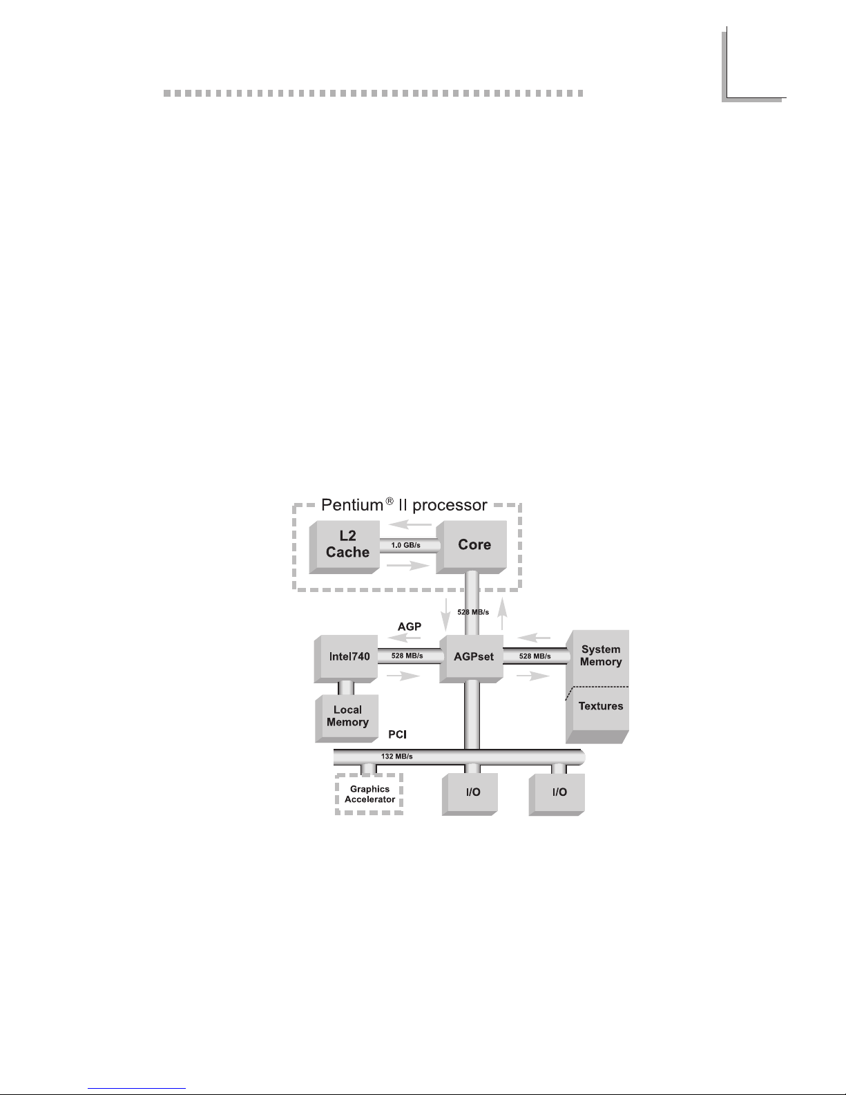
The high performance 3D graphics card uses the Accelerated Graphics
Port (AGP) interface. AGP utilizes a dedicated pipeline to access system
memory for texturing, z-buffering and alpha blending.
Equipped with the Intel740 graphics chip, its HyperPipelined 3D
architecture provides the following features: Precise Pixel Interpolation
(PPI), Parallel Data Processing (PDP) and Direct Memory Execution (DME).
Precise Pixel Interpolation delivers good image quality, Parallel Data
Processing allows consistent high performance and Direct Memory
Execution delivers 528MB/sec bandwidth providing seamless access to
system memory for unlimited texture sizes and rich rendering. The graphics
chips 3D architecture enables maximum memor y bandwidth for sustained
3D performance and exceptional image quality in PCs equipped with
the Pentium II processor and AGPset.
Use the graphics card with softwares that support 3D and enjoy more
texture and higher screen resolution at higher frame rates. The graphics
card will deliver faster and better graphics to your PC.
Page 6

1
6
AGP-7400 Graphics Card Users Manual
Features and Specifications
CHIPSET
Intel740 graphics chip
MEMORY
4MB or 8MB onboard
Supports 64-bit memory interface
Uses 256Kx32 or 512Kx32 100MHz SGRAM
GRAPHICS RESOLUTIONS
4MB: 1600x1200, 256 colors
1600x1200, 32K/64K colors
1024x768, 16M colors
8MB: 1600x1200, 256 colors
1600x1200, 32K/64K colors
1600x1200, 16M colors
2D GRAPHICS FEATURES
Supports single cycled 2D BitBLT graphics engine with:
- 3 Operand Raster BitBLT
- Stretch BitBLT
- Color expansion
- Hardware overlay engine
- Hardware double buffering
- Stretch BLT
- Hardware cursor (64x64x3)
3D GRAPHICS FEATURES
Setup engine balances the 3D pipeline
- 1.2M triangles/sec peak
- 425-500K triangles/sec full feature
- 45-55M pixels/sec full feature
- Full sideband AGP
- Parallel execution
Page 7

1
7
Introduction
3D graphics visual enhancement
- Flat and Gouraud shading
- MIP mapping with bi-linear filtering
- Color alpha blending for transparency
- Real time texture paging and video texturing
- Fogging and atmospheric effects
- Specular lighting
- Edge anti-aliasing
- Stippling or "screen door" transparency
- Backface culling
- Z-buffering
Texture mapping enhancement
- Per pixel perspective correct texture mapping
- Texture sizes from 1x1 to 1024x1024 pixels
- Integrated hardware palette
- Multi-texture formats
- Texture color keying
- Texture chroma keying
COMPATIBILITY
Microsoft PC 98
VESA Display Power Management Signaling (DPMS)
VESA DDC2B for Plug and Play monitors
VESA VBE 2.0 BIOS
Intel AGP version 2.0 sideband DME mode
VMI 1.4 compliant
BENCHMARKS
(Intel Pentium® II processor 300MHz, 1024x768, hi-color, 75Hz, 4MB)
3D Winbench 98: over 650 megapixels/sec.
SOFTWARE DRIVERS
Windows® 95/DirectX5
Windows NT® 4.0
I/O SLOT
AGP slot (AGP 2.0)
Page 8

1
8
AGP-7400 Graphics Card Users Manual
CONNECTOR
1 15-pin analog VGA connector
1 feature connector or VMI (Video Module Interface) connector
Package Checklist
The graphics card
The user's manual
One set of diskette or CD
If any of these items are missing or damaged, please contact your
dealer or sales representative for assistance
Page 9

2
Hardware Installation
CHAPTER
Page 10

2
10
AGP-7400 Graphics Card Users Manual
Carefully read this chapter before installing the graphics card into
your system. Installing the card incorrectly may damage your com-
puter system, monitor, and the card.
Board Layout
Intel740
BIOS
J3
square denotes pin 1
VGA
connector
U7 U8
U9
U10
Feature connector
J6
J5
Video
Module
Interface
(VMI)
SGRAM
SGRAM
SGRAM
SGRAM
Memory
The graphics card may come with 4MB or 8MB of SGRAM (Syn-
chronous Graphics RAM). A 4MB graphics card is installed with four
256Kx32 SGRAMs while an 8MB graphics card is installed with four
512Kx32 SGRAMs. These SGRAMs are installed at locations U7,
U8, U9 and U10 of the graphics card.
Page 11

2
11
Hardware Installation
VMI Interface
The graphics card supports a VMI (Video Module Interface) interface.
This interface is used for connecting a video module, such as a
MPEG module, to a Video Ready GUI device. The VMI interface
consists of the J5 (40-pins) and J6 (26-pins) connectors.
1. Position the VMI module by aligning the connectors on the
module to J5 and J6 of the graphics card.
2. Make sure pin 1 of the connectors on the VMI module is aligned
with pin 1 of J5 and J6 on the graphics card.
3. Press both sides of the VMI module firmly onto the graphics
card. Make sure the VMI module is seated properly.
Installing the Graphics Card
For most computer systems, you will only need a medium size
Phillips screwdriver to remove the cover and a small flat-blade
screwdriver to secure the monitor cable.
Warning:
Electrostatic discharge (ESD) can damage your graphics card,
system board, processor, disk drives, add-in boards, and other
components. Perform the upgrade instruction procedures
described at an ESD workstation only. If such a station is not
available, you can provide some ESD protection by wearing an
antistatic wrist strap and attaching it to a metal part of the
system chassis. If a wrist strap is unavailable, establish and
maintain contact with the system chassis throughout any
procedures requiring ESD protection.
Handling the Graphics Card
It is quite easy to inadvertently damage your graphics card even
before installing it in your system unit. Electrostatic discharge can
damage computer components without causing any signs of physical
damage. You must take extra care in handling the graphics card to
ensure that no static build-up is present.
Page 12

2
12
AGP-7400 Graphics Card Users Manual
Tips in Handling the Graphics Card
1. To prevent electrostatic build-up, leave the graphics card in its
anti-static bag until you are ready to install it.
2. Do all preparation work on a static-free surface with graphics
card components facing up.
3. Hold the graphics card by its edges only. Be careful not to touch
any of the components, contacts or connections, especially gold
contacts, on the board.
Step 1: Switch Off Your Computers Power
Make sure that your computer is switched off and unplugged before
removing the cover. Also turn off any devices (printer, display, mo-
dem, etc.) you may have attached to your computer.
Warning:
Hazardous voltages are present and exposed when operating
the computer with the cover removed. To prevent equipment
damage and personal injury, never apply power to the com-
puter when the cover is off.
Step 2: Remove Your Computers Cover
Refer to your computer system manual for specific instructions on
removing your computers system unit cover. In general, you will need
to remove several screws on the back or side of the system unit and
then slide the cover off.
Step 3: Remove the Slot Cover
Remove the screw and slot cover (that corresponds to the AGP slot)
located at the back of the system unit. Save the slot cover for future
use. You will be using the screw in step 5.
Step 4: Unpack the Graphics Card
Remove the graphics card from the shipping box and its protective
packing. Please do not throw away the packing material or the shipping
box. You may use these again to prevent damage should you need to
ship the graphics card for repairs.
Page 13

2
13
Hardware Installation
Step 5: Insert the Graphics Card
Carefully slide the graphics card into the AGP slot. When the cards
edge-connector is aligned with the slot on the system board, press
firmly on the top of the card to seat it. Make sure the graphics card
is straight and level compared to the computers system board by
viewing it from the side. Once you are satisfied with its alignment,
replace the slot covers screw on top of the cards bracket and gently
tighten the screw to stabilize the card.
Step 6: Replace the Computers Cover
When you have finished installing the graphics card, put the cover back
on your computer's system unit. Refer to your computer's system
manual for instructions if necessary.
Note:
The graphics card can only be used with an analog video display
using a 15-pin D-shell cable connector (standard VGA monitor
connection). If your monitor supports analog video but does not
have a 15-pin D-shell connector, see your monitor dealer for the
adapter or optional cable.
After you plug the monitor cable into the VGA connector of the
graphics card, gently tighten the cable screws to hold the connector in
place.
Note:
Some monitors have a switch that chooses between analog and
TTL (or digital) operation. If your monitor has such a switch, set
it for analog.
Page 14

3
14
AGP-7400 Graphics Card Users Manual
3
Supported Softwares
CHAPTER
Page 15

3
15
Supported Softwares
Operating System Requirements
To use all AGP features, your system must be installed with Windows
®
95 OSR 2.1 or later versions, and DirectX5. If your system is installed
with Windows® 95 OSR 2.0, you may upgrade it to OSR2.1 by
following the steps in the next section.
Upgrading Windows® 95 OSR2.0 to OSR2.1
You must have OSR2.0 already installed before you can upgrade it to
OSR2.1. To determine the current version of OSR2.0 installed in your
system, please follow the steps below.
1. On the Windows® 95 desktop, select Start.
2. In Start, select Programs.
3. In Programs, select MS-DOS Prompt.
4. Change the directory to the drive where Windows® 95 is
installed and type VER. (e.g. C:\>VER)
5. The following will appear: Windows 95 [Version 4.00.1111].
6. Exit MS-DOS Prompt.
To upgrade OSR2.0 to OSR2.1 with the USB upgrade, please follow
the steps below.
1. On the Windows® 95 desktop, select Start.
2. In Start, select Run.
3. In Run, select Browse. The USB upgrade is in
OSR2\USBSUPP\USBSUPP.EXE.
4. Follow the prompts to complete installation.
5. Click OK to restart your computer.
Page 16

3
16
AGP-7400 Graphics Card Users Manual
After booting-up Windows® 95, follow the steps below to
determine the installed version of the operating system.
1. On the Windows® 95 desktop, select Start.
2. In Start, select Run.
3. In Run, type REGEDIT and click OK.
4. The Registry Editor dialog box will appear. In My Computer,
select the following: HKEY_LOCAL_MACHINE\SOFTWARE\
MICROSOFT\WINDOWS\CurrentVersion.
5. On the right side of the dialog box, scroll down and look for
Version Number. It should be 4.03.1212 or later version.
VGA Drivers
The graphics card supports VGA drivers for different operating
systems. Please refer to the README file contained in the provided
diskette/CD for installation instructions.
All steps or procedures to install the VGA drivers are subject to
change without notice as the softwares are occassionally updated.
Please refer to the "Readme" files contained on the provided diskette/
CD for the latest information.
Page 17

A
Connector Pin Assignments
APPENDIX
Page 18

A
18
AGP-7400 Graphics Card Users Manual
Connectors J5 and J6
VMI Interface
The VMI interface consists of the J5 (40-pins) and J6 (26-pins)
connectors. This interface is used for installing a VMI module. J6 alone
is a feature connector. Refer to the next page for the pin assignment
of J6.
Pin
1
2
3
4
5
6
7
8
9
10
11
12
13
14
15
16
17
18
19
20
Description
HD[0]
Ground
HD[2]
HD[4]
HD[5]
HD[7]
HA[0]
HA[2]
+5V
RESET#
Ground
WR#
READY
INTREQ#
PCMDATA
+3.3V
User Defined
KEY
AUDIOL
AUDIOR
Pin
21
22
23
24
25
26
27
28
29
30
31
32
33
34
35
36
37
38
39
40
Description
+12V
HD[1]
Ground
HD[3]
+5V
HD[6]
OSC
HA[1]
HA[3]
Ground
CS#
RD#
+3.3V
SCLK
LRCK
+5V
User Defined
User Defined
INSERT#
AUDGND
Page 19

A
19
Connector Pin Assignments
Connector J3
VGA Connector
Pin
1
2
3
4
5
6
7
8
Description
Red
Green
Blue
Monitor ID bit 2
Ground
Red Return (ground)
Green Return (ground)
Blue Return (ground)
Pin
9
10
11
12
13
14
15
Description
+5V Vcc
Sync Return (ground)
Not Used
SDA
Horizontal Sync
Vertical Sync
SCL
Connector J6
Feature Connector
Pin
1
2
3
4
5
6
7
8
9
10
11
12
13
Description
P0
P1
P2
P3
P4
P5
P6
P7
DCLK
BLANK#
HSYNC
VSYNC
Ground
Pin
14
15
16
17
18
19
20
21
22
23
24
25
26
Description
Ground
Ground
Ground
EVIDEO#
ESYNC#
EDCLK#
N/C
Ground
Ground
Ground
Ground
N/C
N/C
Page 20

B
20
AGP-7400 Graphics Card Users Manual
B
Glossary of 3D Features
CHAPTER
Page 21

B
21
Glossary of 3D Features
Alpha Blending - using the alpha component to proportionally weight
the intensity of an object in the summation of all objects within a pixel.
When done correctly, alpha blending can simulate transparency.
Antialiasing - an algorithm to remove the distracting effects of point
sampling a signal in the digital domain. This is necessary because some
of the frequencies present in the signal may be higher than half the
sampling rate. These frequency components "alias" as lower frequency
signals, and show up as "jaggies".
Bilinear Interpolation - an interpolation between four values when
fractional deltas are known in the vertical and horizontal direction.
The horizontal delta is used as the weighting factor to average the
top left and top right values to determine the top, and the bottom
left and bottom right to determine the bottom. The vertical delta is
then used as the weighting factor between the top and bottom value
to calculate the final result.
Direct Memory Execution (DME) - DME is a technique that allows
the graphics accelerator to store and execute textures in system
memory instead of local graphics memory. This provides high levels of
performance and unlimited texture sizes.
Double Buffering - refers to maintaining two separate frame bufffers
(which may physically occupy the same RAM devices). This implies
performing display refreshes from one buffer, while the rendering is
accessing the other one.
Mip Mapping - Mip comes from the Latin, multum in parvo, meaning
many things in a small place. Mip maps contain the original bitmap,
and all successively lower levels of detail. These are usually created by
filtering the original map, decreasing its size by powers of two in both
directions.
Parallel Data Processing (PDP) - PDP contributes to the
HyperPipelined 3D architecture. This is a method of parallelizing 3D
operations allowing several commands to be executed at the same
time in the graphics pipeline. This translates into consistent high-perfor-
mance regardless of the number of features enabled in a scene.
Page 22

B
22
AGP-7400 Graphics Card Users Manual
Perspective Correction - correctly adjusting the interpolation of poly-
gon attributes (primarily texture addresses) so that they appear to
obey the rules of perspective. Perspectively correct interpolation is not
linear in screen space, and requires a divide by depth in order to look
right.
Precise Pixel Interpolation (PPI) - PPI contributes to the
HyperPipelined 3D quality with Intels unique texture engine that deliv-
ers precise accuracy in interpolation operations of pixel values and
color values. This detailed pixel processing maintains a high level of
image quality in every scene.
Shading, Flat - darkening or lightening the intensity of a polygon
based on the angle between its normal and a vector pointing to a
light source. All pixels on a polygon receive the same adjustment,
resulting in a faceted appearance. The per polygon and per pixel cal-
culation load is very light.
Shading, Gouraud - darkening or lighting each pixel of a polygon
based on an interpolation between values calculated at the polygon's
vertices. A "vertex normal" is prescribed or inferred, and the intensity
at that vertex is determined by the angle between that normal and a
vector pointing to a light source. Each pixel is interpolated separately,
producing a simulation of a curved surface. Gouraud shading makes
objects appear to have a matte finish, with no specular components.
The per polygon and per pixel calculation load is moderate.
Z Buffer - a buffer memory that holds the Z (depth) information per
pixel. The Z axis is perpendicular to the X and Y axis of the screen,
and in most practical cases inverse range is uded due to the fact that
it is linear in screen space (where range is not). Compares in depth
between pixels of two polygons can be used to determine occulting
relationships, and only draw the nearer polygon for each pixel.
 Loading...