

DFI AD73 Pro User Manual

AD73 Pro
Rev. A+
System Board User’s Manual
Carte Mère Manuel Pour Utilisateur
System-Platine Benutzerhandbuch
Manual del Usuario de Placas Base
55100205

Copyright
This publication contains information that is protected by copyright.
No par t of it may be reproduced in any form or by any means or
used to make any transformation/adaptation without the prior
written permission from the copyright holders.
This publication is provided for informational purposes only. The
manufacturer makes no representations or warranties with respect to
the contents or use of this manual and specifically disclaims any
express or implied warranties of merchantability or fitness for any
particular purpose. The user will assume the entire risk of the use or
the results of the use of this document. Further, the manufacturer
reserves the right to revise this publication and make changes to its
contents at any time, without obligation to notify any person or
entity of such revisions or changes.
© 2002. All Rights Reserved.
Trademarks
Microsoft® MS-DOS®, WindowsTM, Windows® 95, Windows® 98,
Windows® 98 SE, Windows® ME, Windows® 2000, Windows NT
®
4.0 and Windows® XP are registered trademarks of Microsoft
Corporation. AMD, AthlonTM and DuronTM are registered trademarks
of Advanced Micro Devices, Inc. VIA is a registered trademark of
VIA Technologies, Inc. Award is a registered trademark of Award
Software, Inc. Other trademarks and registered trademarks of
products appearing in this manual are the properties of their
respective holders.
Caution
To avoid damage to the system:
• Use the correct AC input voltage range.
To reduce the risk of electric shock:
• Unplug the power cord before removing the system chassis
cover for installation or servicing. After installation or servicing,
cover the system chassis before plugging the power cord.

Battery:
• Danger of explosion if battery incorrectly replaced.
• Replace only with the same or equivalent type recommend by
the manufacturer.
• Dispose of used batteries according to the battery
manufacturer’s instructions.
Joystick or MIDI port:
• Do not use any joystick or MIDI device that requires more than
10A current at 5V DC . There is a risk of fire for devices that
exceed this limit.
FCC and DOC Statement on Class B
This equipment has been tested and found to comply with the limits
for a Class B digital device, pursuant to Part 15 of the FCC rules.
These limits are designed to provide reasonable protection against
harmful interference when the equipment is operated in a residential
installation. This equipment generates, uses and can radiate radio
frequency energy and, if not installed and used in accordance with
the instruction manual, may cause harmful interference to radio
communications. However, there is no guarantee that interference
will not occur in a particular installation. If this equipment does cause
harmful interference to radio or television reception, which can be
determined by turning the equipment off and on, the user is
encouraged to try to correct the interference by one or more of the
following measures:
• Reorient or relocate the receiving antenna.
• Increase the separation between the equipment and the receiver.
• Connect the equipment into an outlet on a circuit different from
that to which the receiver is connected.
• Consult the dealer or an experienced radio TV technician for
help.
Notice:
1. The changes or modifications not expressly approved by the
party responsible for compliance could void the user's authority
to operate the equipment.
2. Shielded interface cables must be used in order to comply with
the emission limits.

4
Quick Setup Guide
1
Quick Setup
Guide
Table of Contents
Chapter 1
Quick Setup Guide.............................................
Chapter 2
English......................................................................
Chapter 3
Français (French).................................................
Chapter 4
Deutsch (German)................................................
Chapter 5
Español (Spanish)..................................................
5
23
41
61
81
Note:
The user’s manual in the provided CD contains detailed information
about the system board. If, in some cases, some information doesn’t
match those shown in this manual, this manual should always be
regarded as the most updated version.

5
1
Quick Setup Guide
Quick Setup
Guide
Chapter 1 - Quick Setup Guide
Table of Contents
1.1 System Board Layout..................................................................................................
1.2 Jumpers.....................................................................................................................................
1.3 Ports and Connectors................................................................................................
1.4 Award BIOS Setup Utility.......................................................................................
6
7
10
18
Important:
To ensure proper boot up and operation of your system, you must
power-off the system then turn off the power supply’s switch or
unplug the AC power cord prior to altering the setting of a jumper
or replacing the CPU.

6
Quick Setup Guide
1
Quick Setup
Guide
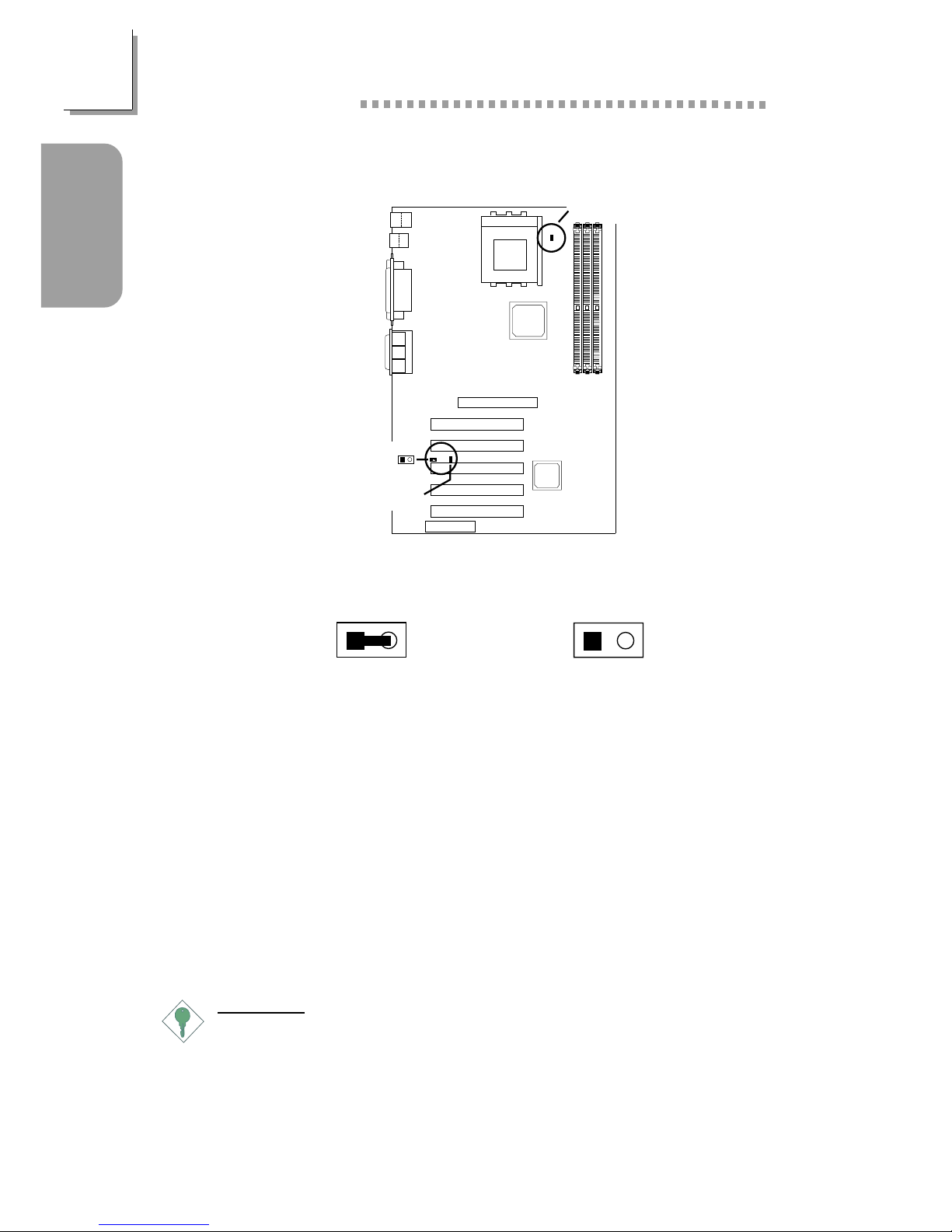
1.1 System Board Layout
J6
KB
Mouse
USB
USB 1
(J7)
USB
COM 1 (J1)
Parallel (J8)
COM 2 (J2)
Game/MIDI (J12)
Line
out
(J3)
Line
in
(J4)
Mic
in
(J5)
CD-in (J13)
AUX-in (J14)
CPU fan
(J16)
Power select
USB 1 (JP4)for
PS/2 power
select (JP3)
Socket 462
(Socket A)
DIMM
standby
power LED
DDR SDRAM
DIMM 1
DDR SDRAM
DIMM 2
DDR SDRAM
DIMM 3
Primary IDE (J22)
Secondary IDE (J23)
VIA
KT-266A
VIA
VT8233ACD
CPU FSB
select (JP8)
Wake-On-Ring
(J26)
FDD (J24)
Wake-On-LAN
J19
Clear CMOS (JP9)
PWR-LED
ATX-SW
G-LED
G-SW
Chassis fan
(J21)
HD-LED
RESET
SPEAKER
USB 2 (J20)
CNR setting (JP6)
Power select
USB 2 (JP7)for
Winbond
W83697HF
BIOS
JP1
JP2
IrDA
(J11)
Onboard audio
codec settings
(JP1 & JP2)
AC’97
PCI standby power LED
3.3VSB standby for PCI (JP5)
AGP Slot
PCI Slot 1
PCI Slot 2
PCI Slot 3
PCI Slot 4
PCI Slot 5
CNR Slot
TAD (J15)
Front audio
(J9)
ATX p ow er
(J17)
Second chassis
fan (J18)
9
10
2
1
1
11
5
15
J25
USB 1
(Black)
Mouse
(Green)
KB
(Purple)
COM 1
COM 2
Parallel
(Burgundy)
Game/MIDI
(Gold)
Line-In
(Light Blue)
Line-Out
(Lime)
Mic-In
(Pink)
USB 2
(Black)
(Teal/Turquoise)
7
1
Quick Setup Guide
Quick Setup
Guide
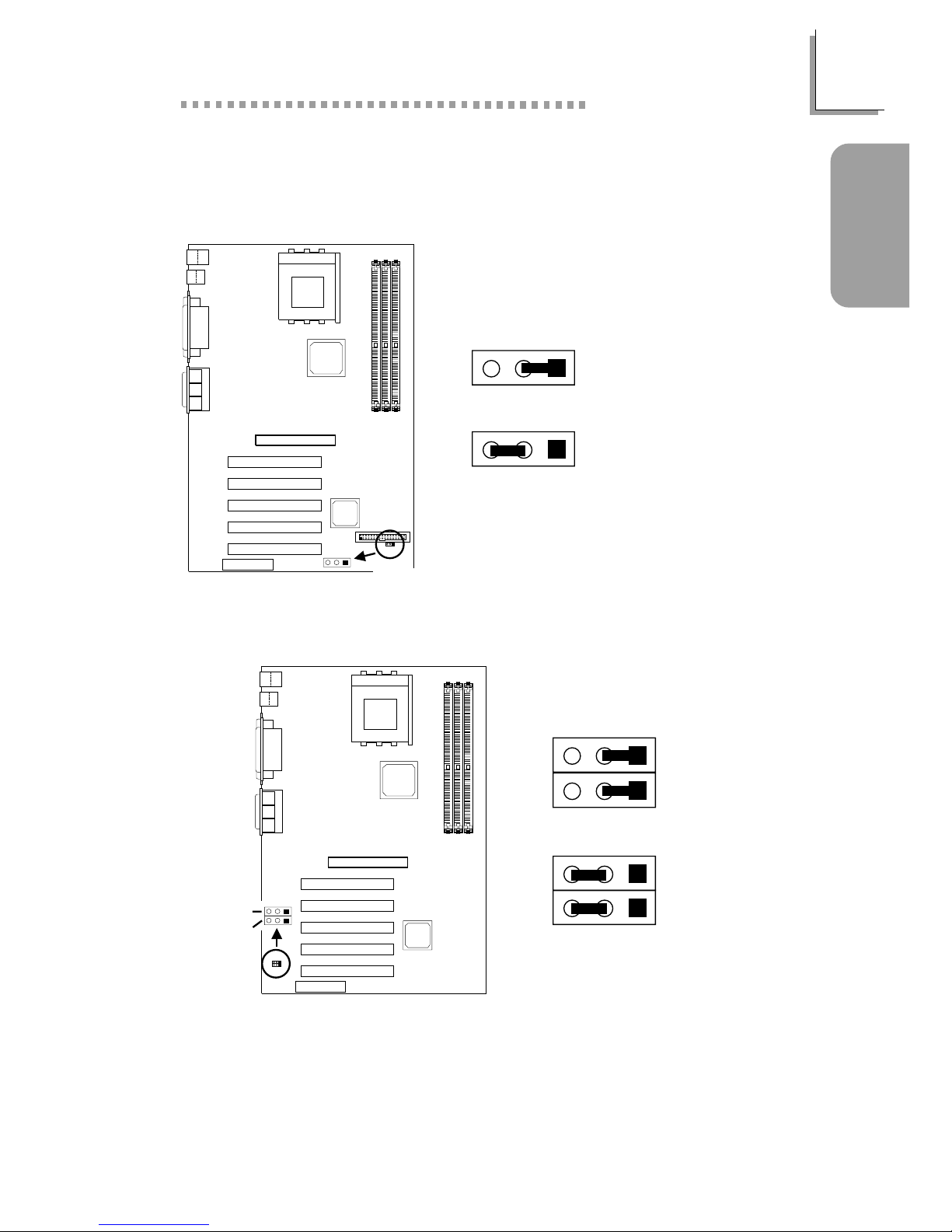
1.2 Jumpers
321
Clear
CMOS (JP9)
1.2.1 Clear CMOS Data - JP9
2-3 On:
Clear CMOS Data
1-2 On:
Normal (default)
321
321
1.2.2 Onboard Audio Codec - JP1 and JP2
1-2 On:
Enable the
Onboard Audio
Codec (default)
2-3 On: Disable
the Onboard
Audio Codec
If you are not using the onboard audio codec, set pins 2 and 3 to On
(Disabled) and set the “VIA-3058 AC97 Audio” (“VIA OnChip PCI
Device” field) in the Integrated Peripherals submenu of the BIOS to
Disabled.
JP1
Onboard audio
codec settings
(JP1 & JP2)
321
JP2
JP1
321
JP2
JP1
JP2
321
8
Quick Setup Guide
1
Quick Setup
Guide
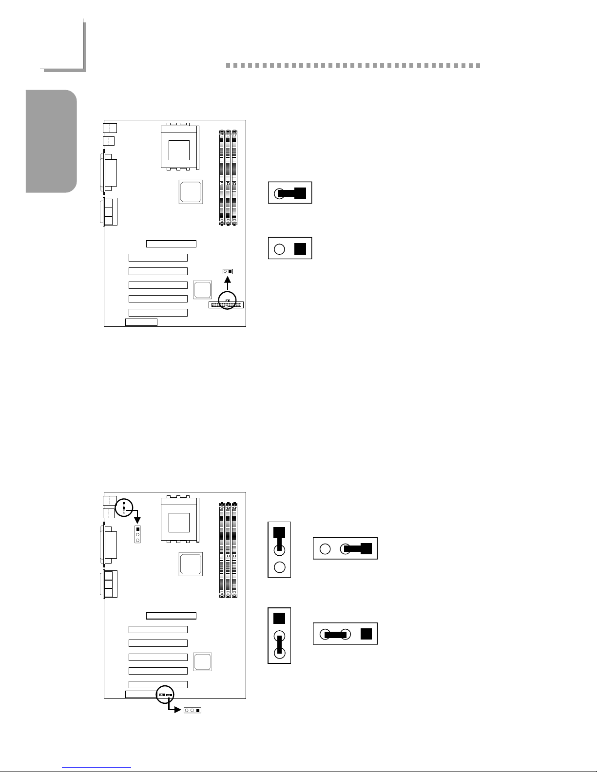
1.2.4 Power Select for USB 1 (JP4) and USB 2 (JP7)
2-3 On:
5VSB
1-2 On:
5V (default)
1.2.3 CPU’s Front Side Bus - JP8
On: 100MHz
(200MHz DDR) CPU
(default)
Off: 133MHz
(266MHz DDR) CPU
To ensure proper boot up and operation of your system, you must poweroff the system then turn off the power supply’s switch or unplug the AC
power cord prior to altering the setting of the jumper.
When using a 1.2GHz CPU under Windows® XP operating system, the
VIA KT-266A chip must be installed with a fan that is connected to the
“second chassis fan” connector.
1
2
CPU FSB
select (JP8)
21
21
Power select
USB 2 (JP7
)
for
Power select
USB 1 (JP4)for
1
2
3
321
1
2
3
JP4
1
2
3
JP4
JP7
JP7
321
3
21
9
1
Quick Setup Guide
Quick Setup
Guide
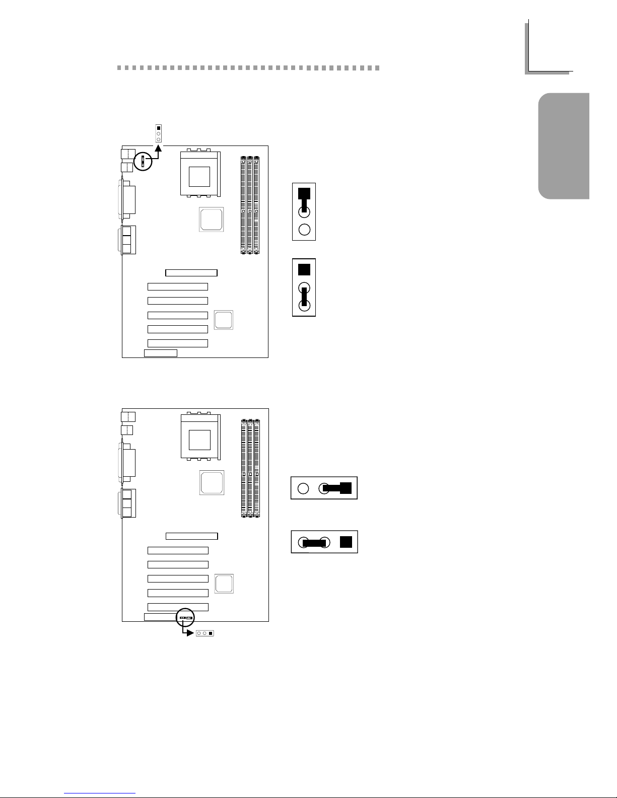
1.2.6 CNR Settings - JP6
2-3 On:
Secondary
1-2 On:
Primary (default)
1.2.5 Power Select for PS/2 Keyboard/Mouse (JP3)
PS/2 power
select (JP3)
1
2
3
1
2
3
1
2
3
2-3 On:
5VSB
1-2 On:
5V (default)
321
CNR setting
(JP6)
321
3
21
10
Quick Setup Guide
1
Quick Setup
Guide
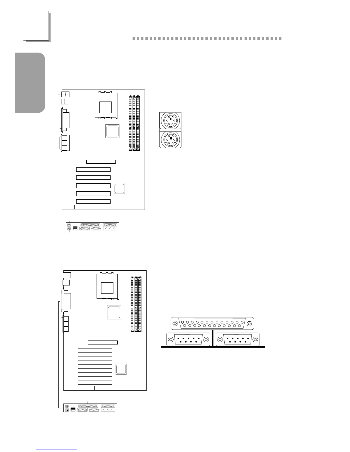
1.3 Ports and Connectors
1.31 PS/2 Mouse and PS/2 Keyboard Ports
Make sure to turn off your computer
prior to connecting or disconnecting a
mouse or keyboard. Failure to do so
may damage the system board.
PS/2 Mouse
PS/2 Keyboard
1.3.2 Parallel Port
Parallel Port
J6
Mouse
(Green)
KB
(Purple)
Parallel
(Burgundy)
J8
11
1
Quick Setup Guide
Quick Setup
Guide
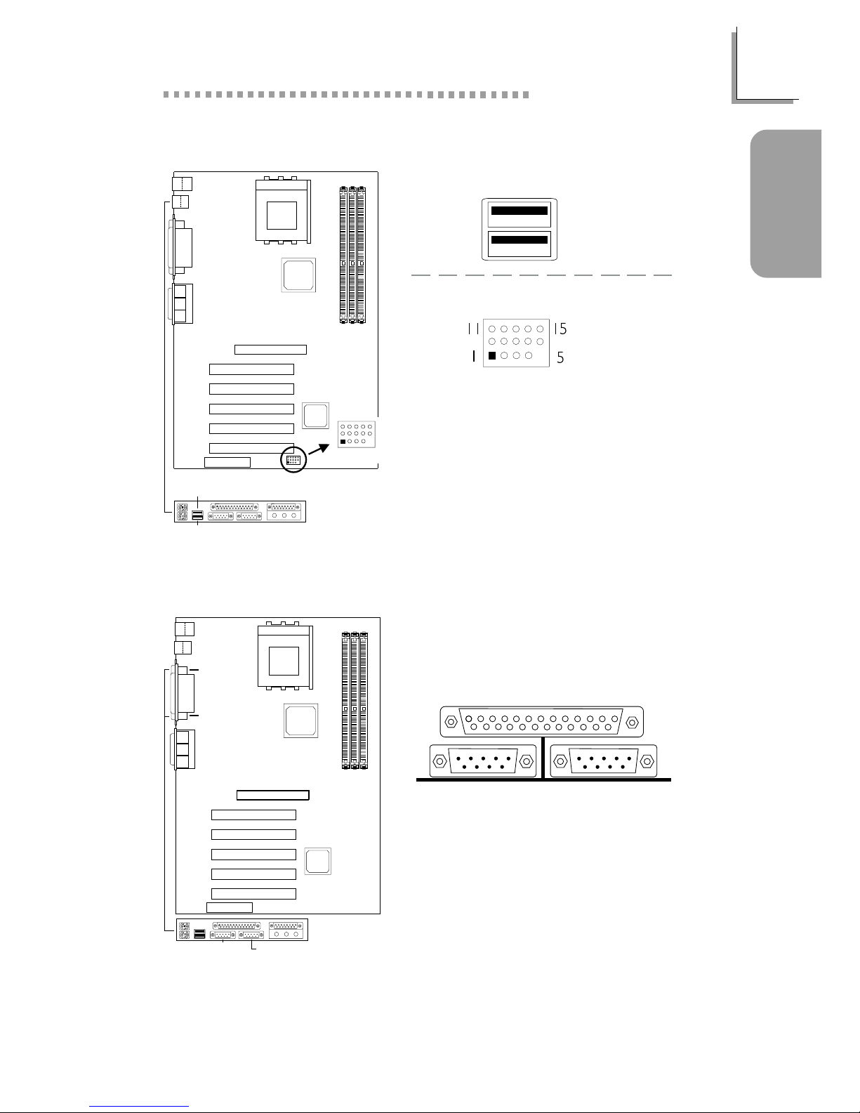
1.3.3 Universal Serial Bus Ports
1.3.4 Serial Ports
COM 1
Serial Port
COM 2
Serial Port
1 VCC
2 UP23 UP2+
4 Ground
5 Key
6 VCC
7 UP38 UP3+
9 Ground
10 Ground
11 Ground
12 Ground
13 UP2+
14 UP215 VCC
Onboard USB Ports (J7)
Additional USB Ports (J20)
J1
COM 1
COM 2
(Teal/Turquoise)
J2
J7
USB 2
(Black)
USB 1
(Black)
1
11
5
15
5
15
11
1
USB 2 (J20)

12
Quick Setup Guide
1
Quick Setup
Guide
1.3.5 Game/MIDI Port and Audio Jacks
1.3.6 Internal Audio Connectors
Game/MIDI Por t
Audio Jacks
Line-out
Line-in
Mic-in
Front Audio (J9)
1 Mic+
2 Ground
3 Mic Power
4 AuD_Vcc (Avcc)
5 AuD_R-Out
6 AuD_R_Return (GND)
7N. C.
8 Key
9 AuD_L_Out
1 0 AuD_L_Return (GND)
1 Left audio channel
2 Ground
3 Ground
4 Right audio channel
AUX-in / CD-in
Onboard Game/MIDI / Audio
J3
J4
J5
Line-in
(Light Blue)
Line-out
(Lime)
Mic-in (Pink)
Front audio
(J9)
9
10
2
1
9
10
1
2
J12
Game/MIDI
(Gold)
CD-in (J13)
AUX-in (J14)
TAD (J15)
4
3
2
1
1 Modem-out (from modem)
2 Ground
3 Ground
4 Modem-in (to modem)
TAD
13
1
Quick Setup Guide
Quick Setup
Guide
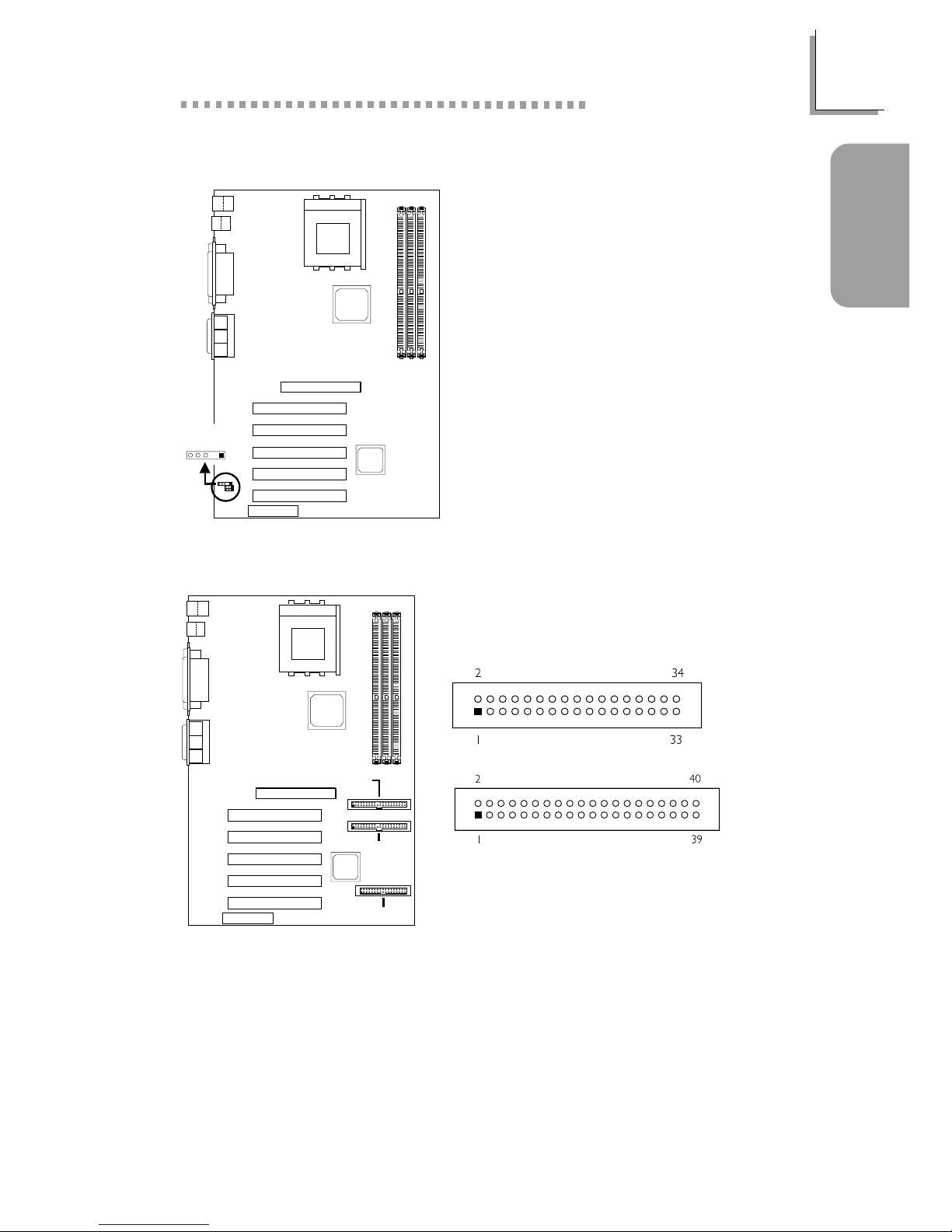
1.3.8 Floppy and IDE Disk Drive Connectors
If you encountered problems while using an ATAPI CD-ROM drive that is
set in Master mode, please set the CD-ROM drive to Slave mode. Some
ATAPI CD-ROMs may not be recognized and cannot be used if
incorrectly set in Master mode.
FDD
IDE
1.3.7 IrDA Connector
1 VCC
2N. C.
3 IRRX
4 Ground
5 IRTX
The sequence of the pin functions on
some IrDA cable may be reversed
from the pin function defined on the
system board. Make sure to connect
the cable to the IrDA connector
according to their pin functions.
Primary IDE
(J22)
Secondary IDE
(J23)
FDD (J24)
54321
IrDA (J11)
14
Quick Setup Guide
1
Quick Setup
Guide
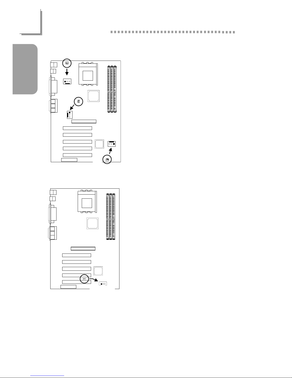
1.3.10 Wake-On-LAN Connector
The 5VSB power source of your power
supply must support ≥720mA.
1 +5VSB
2 Ground
3WOL
1.3.9 Fan Connectors
1On
2 +12V
3 Sense
1 On/Off
2 +12V
3 Sense
1 Ground
2 +12V
3 Ground
CPU Fan
Chassis Fan
Second Chassis Fan
Second chassis
fan (J18)
3
2
1
123
Chassis fan
(J21)
CPU fan
(J16)
321
123
Wake-On-LAN
(J19)
15
1
Quick Setup Guide
Quick Setup
Guide
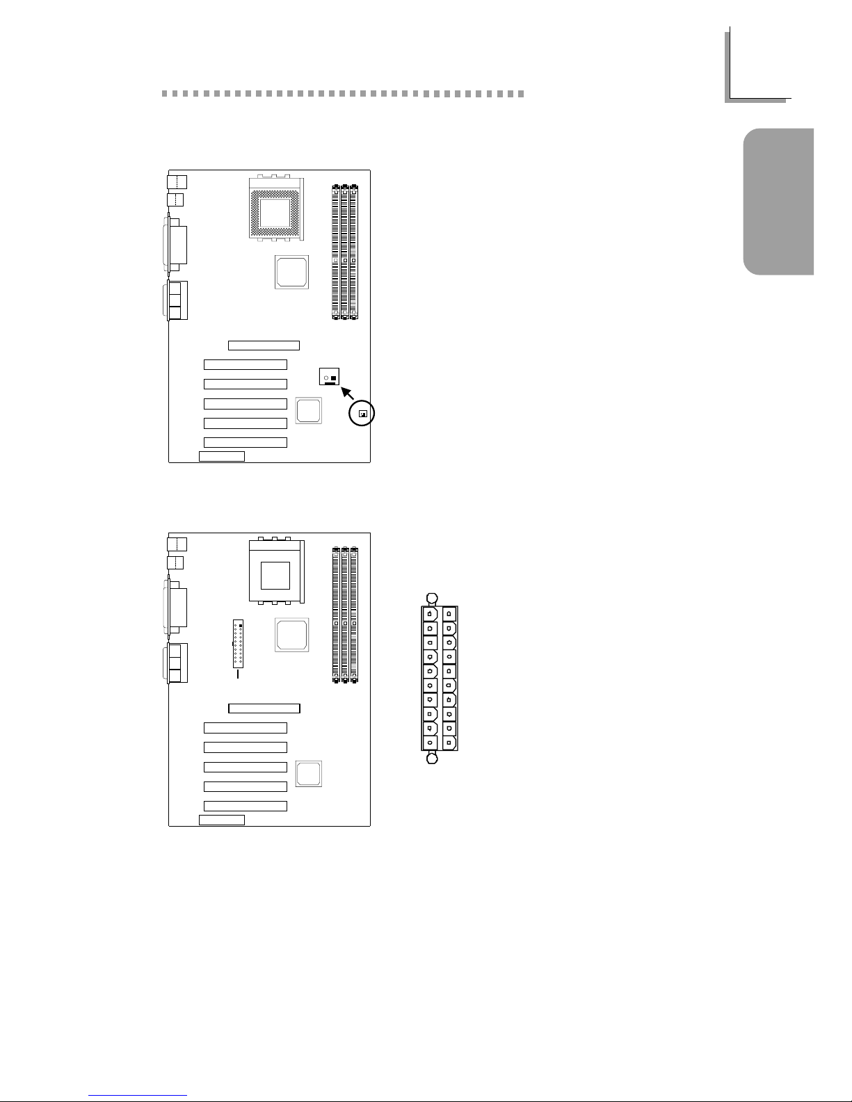
1.3.12 Power Connector
13.3V
23.3V
3 Ground
4+5V
5 Ground
6+5V
7 Ground
8 PW-OK
9 5VSB
10 +12V
11 3.3V
12 -12V
13 Ground
1 4 PS-ON
15 Ground
16 Ground
17 Ground
18 -5V
19 +5V
20 +5V
The system board requires a minimum of 300W electric current.
20
11
10
1
1.3.11 Wake-On-Ring Connector
1 Ground
2RI#
If you are using a modem add-in card,
the 5VSB power source of your power
supply must support ≥720mA.
2
1
Wake-On-Ring
(J26)
ATX power
(J17)
16
Quick Setup Guide
1
Quick Setup
Guide
1.3.13 DIMM and PCI Standby Power LEDs
DIMM Standby Power LED
This LED will turn red when the system’s power is on or when it is in the
Suspend state (Power On Suspend or Suspend to RAM). It will not light
when the system is in the Soft-Off state.
PCI Standby Power LED
This LED will turn red when the system is in the power-on, Soft-Off or
Suspend (Power On Suspend or Suspend to RAM) state.
Important:
Lighted LEDs serve as a reminder that you must power-off the
system then turn off the power supply’s switch or unplug the power
cord prior to installing any memory modules or add-in cards.
3.3VSB Standby for PCI - Jumper JP5
On: Default
3.3VSB Standby Power to
PCI slots - PCI 2.2 spec.
Off:
Non-PCI 2.2 spec.
12
12
DIMM
standby
power LED
2
1
PCI standby
power LED
3.3VSB standby
for PCI (JP5)
17
1
Quick Setup Guide
Quick Setup
Guide
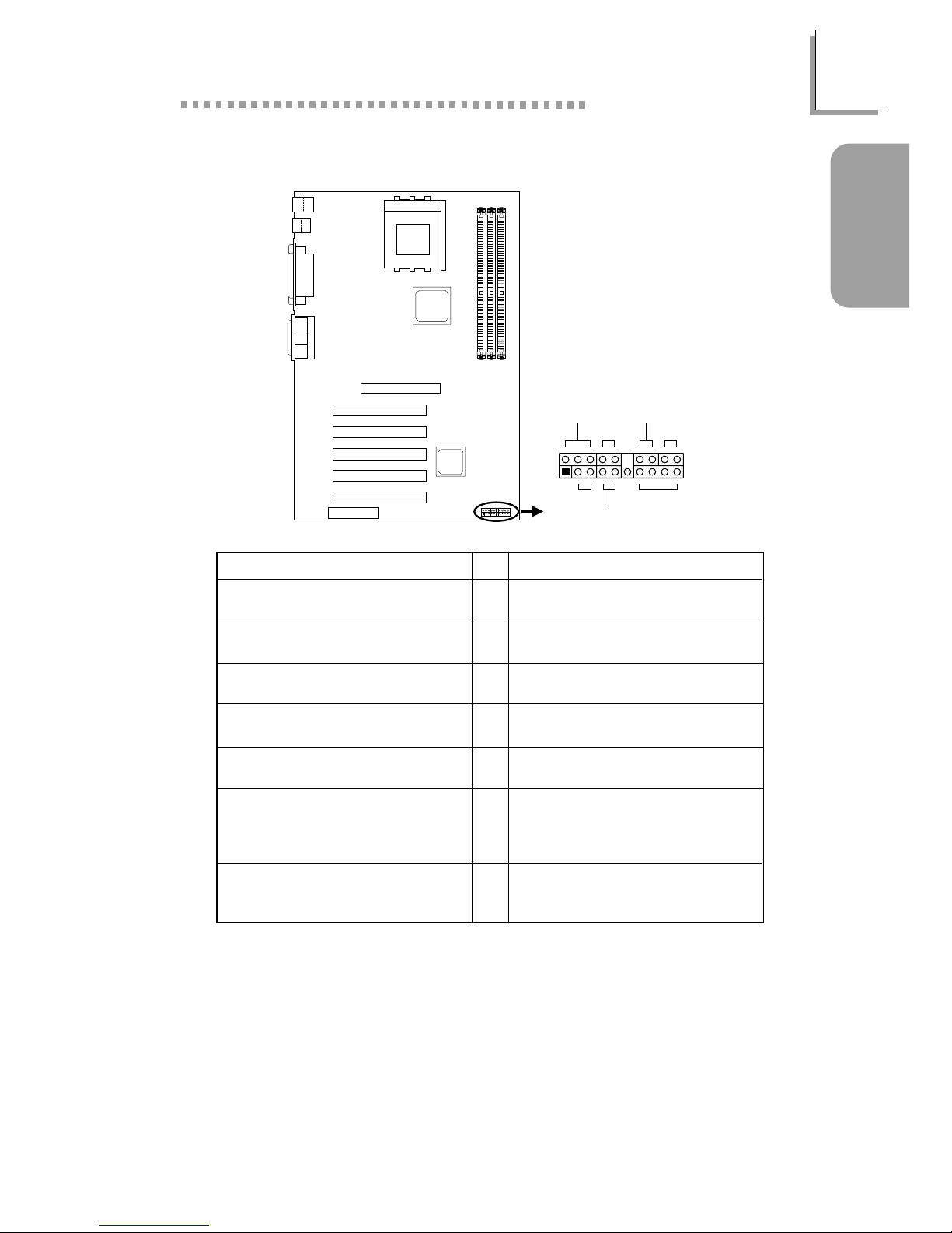
1.3.14 Front Panel Connectors
Pin
3
5
14
16
8
10
18
20
7
9
13
15
17
19
2
4
6
HD-LED
(Primary/Secondary IDE LED)
G-LED
(Green LED)
ATX-SW
(ATX power switch)
G-SW
(Green switch)
RESET
(Reset switch)
SPEAKER
(Speaker connector)
PWR-LED
(Power/Standby LED)
Pin Assignment
HDD LED Power
HDD
Green LED Power
Ground
PWRBT+
PWRBT-
Ground
SMI
Ground
H/W Reset
Speaker Data
N. C.
Ground
Speaker Power
LED Power (+)
LED Power (+)
LED Power (-) or Standby Signal
Front panel
connectors (J25)
PWR-LED
HD-LED
ATX-SW
G-LED
G-SW
RESET
SPEAKER
2
1
20
19
18
Quick Setup Guide
1
Quick Setup
Guide
1.4 Award BIOS Setup Utility
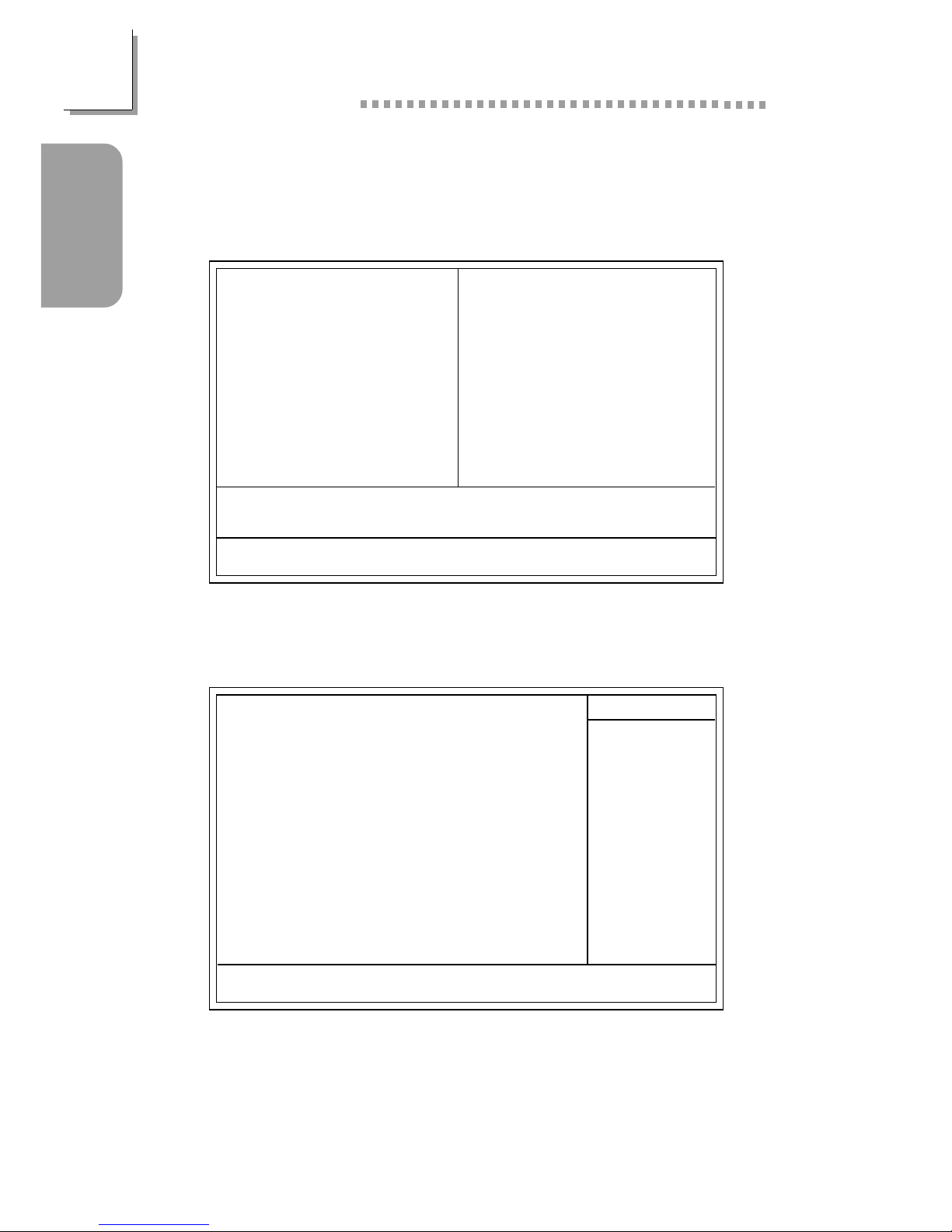
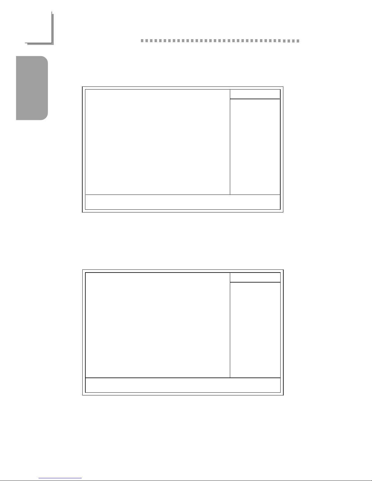
1.4.1 Main Menu
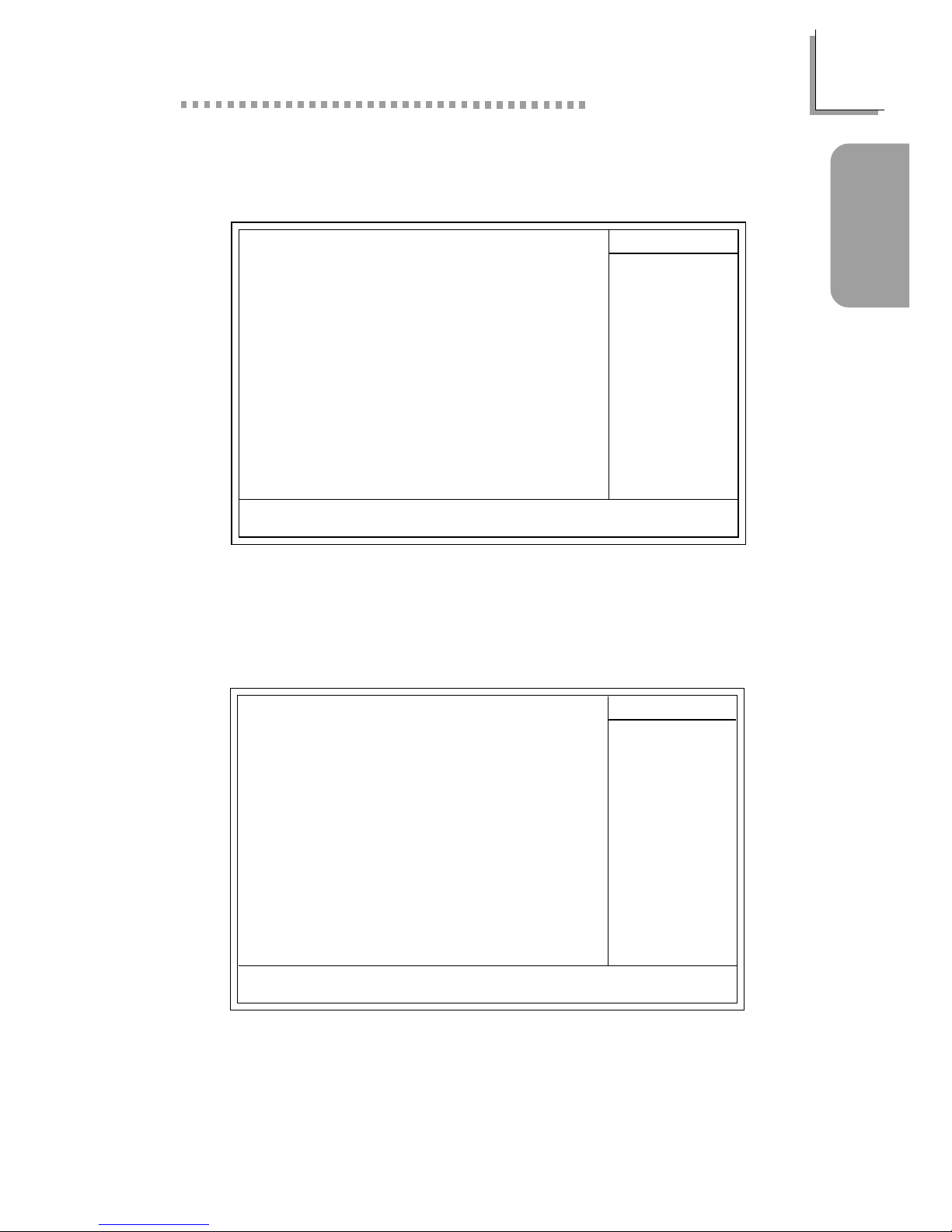
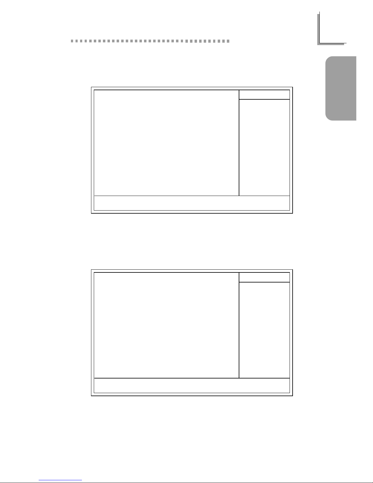
1.4.2 Standard CMOS Features
CMOS Setup Utility - Copyright (C) 1984-2001 Award Software
Standard CMOS Features
Advanced BIOS Features
Advanced Chipset Features
Integrated Peripherals
Power Management Setup
PnP/PCI Configurations
PC Health Status
Frequency/Voltage Control
Load Fail-Safe Defaults
Load Optimized Defaults
Set Supervisor Password
Set User Password
Save & Exit Setup
Exit Without Saving
Esc
F10
: Quit
: Save & Exit Setup
↑↓→←
: Select Item
Time, Date, Hard Disk Type...
The settings on the screen are for reference only. Your version may not be
identical to this one.
↑↓→← :Move
CMOS Setup Utility - Copyright (C) 1984-2001 Award Software
Standard CMOS Features
Date (mm:dd:yy)
Time (hh:mm:ss)
IDE Primary Master
IDE Primary Slave
IDE Secondary Master
IDE Secondary Slave
Drive A
Drive B
Video
Halt On
Base Memory
Extended Memory
Total Memory
F6:Fail-Safe Defaults F7:Optimized Defaults
F1:General Help
Thu, Jan 10 2002
4 : 35 : 5
Press Enter None
Press Enter None
Press Enter None
Press Enter None
1.44M, 3.5 in.
None
EGA/VGA
All, But Keyboard
640K
129024K
130048K
Item Help
Menu Level
Change the day, month,
year and century
Enter:Select
F5:Previous Values
+/-/PU/PD:Value F10:Save ESC:Exit
19
1
Quick Setup Guide
Quick Setup
Guide
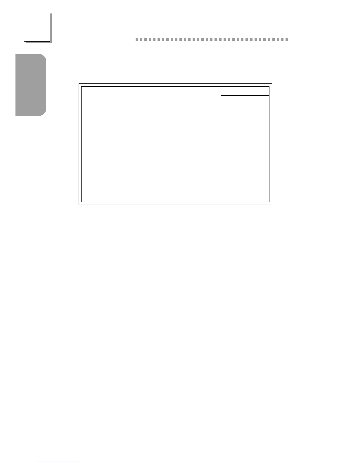
1.4.3 Advanced BIOS Features
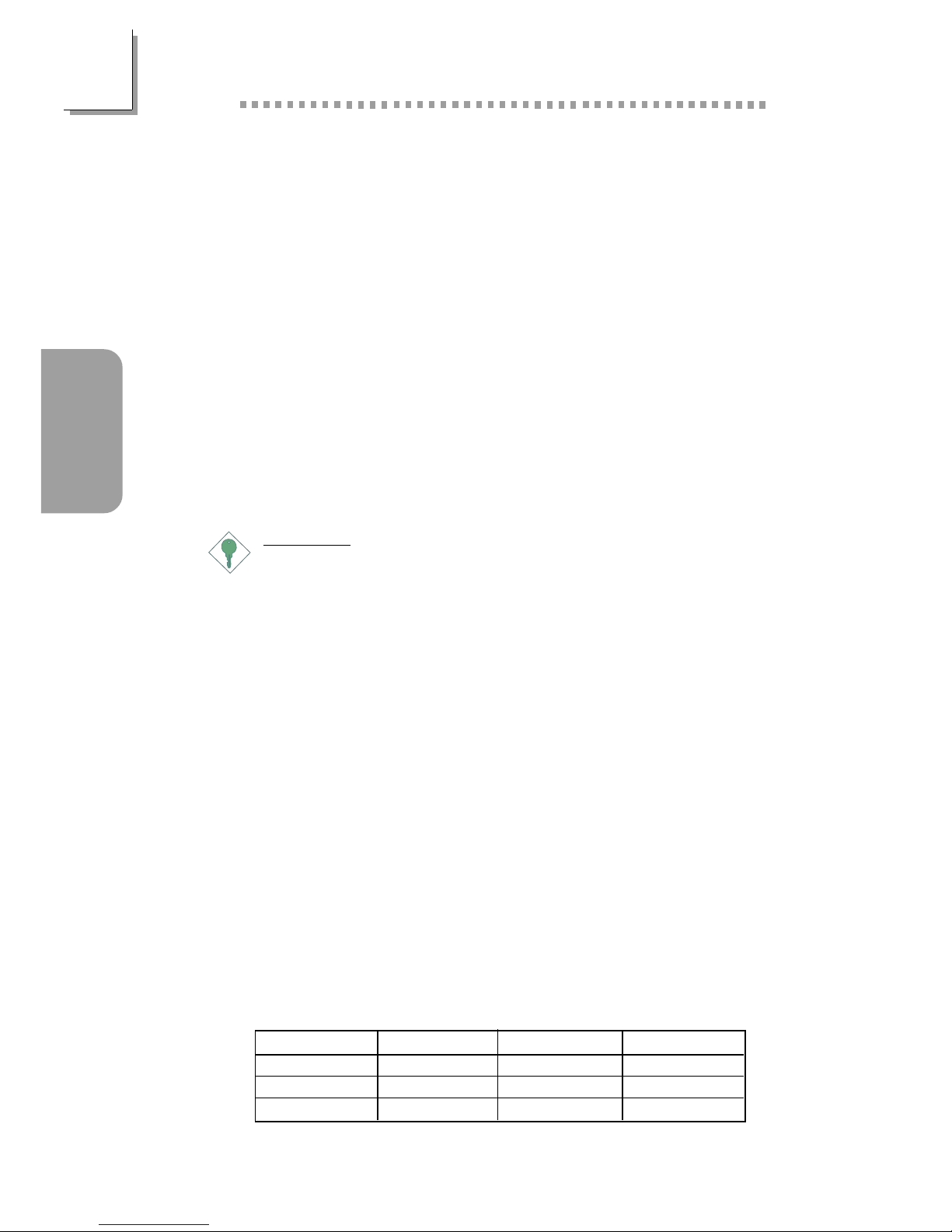
1.4.4 Advanced Chipset Features
CMOS Setup Utility - Copyright (C) 1984-2001 Award Software
Advanced BIOS Features
Item Help
Menu Level
Allows you to choose
the VIRUS warning
feature for IDE Hard
Disk boot sector
protection. If this
function is enabled and
someone attempt to
write data into this
area, BIOS will show a
warning message on
screen and alarm beep
↑↓→← Move F1:General HelpEnter:Select +/-/PU/PD:Value
F10:Save
ESC:Exit
X
X
F6:Fail-Safe Defaults F7:Optimized DefaultsF5:Previous Values
Virus Warning
CPU L1 Cache
CPU L2 Cache
CPU L2 Cache ECC Checking
Quick Power On Self Test
First Boot Device
Second Boot Device
Third Boot Device
Boot Other Device
Swap Floppy Drive
Boot Up Floppy Seek
Boot Up NumLock Status
Typematic Rate Setting
Typematic Rate (Chars/Sec)
Typematic Delay (Msec)
Security Option
OS Select For DRAM > 64MB
HDD S.M.A.R.T. Capability
Small Logo(EPA) Show
Disabled
Enabled
Enabled
Enabled
Enabled
Floppy
HDD-0
LS120
Enabled
Disabled
Disabled
On
Disabled
6
250
Setup
Non-OS2
Disabled
Enabled
The settings on the screen are for reference only. Your version may not be
identical to this one.
CMOS Setup Utility - Copyright (C) 1984-2001 Award Software
Advanced Chipset Features
The settings on the screen are for reference only. Your version ma y not be
identical to this one.
Item Help
Menu Level
↑↓→← Move
F6:Fail-Safe Defaults F7:Optimized Defaults
F1:General HelpEnter:Select
F5:Previous Values
+/-/PU/PD:Value F10:Save ESC:Exit
DRAM Clock/Drive Control
AGP & P2P Bridge Control
CPU & PCI Bus Control
System BIOS Cacheable
Video RAM Cacheable
I/O Recovery Time
Press Enter
Press Enter
Press Enter
Disabled
Disabled
Disabled
20
Quick Setup Guide
1
Quick Setup
Guide
1.4.6 Power Management Setup
1.4.5 Integrated Peripherals
CMOS Setup Utility - Copyright (C) 1984-2001 Award Software
Integrated Peripherals
Item Help
Menu Level
↑↓→← Move
F6:Fail-Safe Defaults F7:Optimized Defaults
F1:General HelpEnter:Select
F5:Previous Values
+/-/PU/PD:Value F10:Save ESC:Exit
VIA OnChip IDE Device
VIA OnChip PCI Device
Super IO Device
Init Display First
OnChip USB Controller
USB Keyboard Support
IDE HDD Block Mode
Press Enter
Press Enter
Press Enter
PCI Slot
All Enabled
Disabled
Disabled
The settings on the screen are for reference only. Your version may not be
identical to this one.
The settings on the screen are for reference only. Your version may not be
identical to this one.
CMOS Setup Utility - Copyright (C) 1984-2001 Award Software
Power Management Setup
ACPI Function
ACPI Suspend Type
Power Management Option
HDD Power Down
Suspend Mode
Video Off Option
Video Off Method
MODEM Use IRQ
Soft-Off By PWRBTN
PWR Lost Resume State
Wake Up Events
Enabled
S1(POS)
User Define
Disabled
Disabled
Suspend -> Off
V/H SYNC+Blank
3
Instant-off
Keep Off
Press Enter
Item Help
Menu Level
↑↓→← Move
F6:Fail-Safe Defaults F7:Optimized Defaults
F1:General HelpEnter:Select
F5:Previous Values
+/-/PU/PD:Value
F10:Save
ESC:Exit
21
1
Quick Setup Guide
Quick Setup
Guide
1.4.7 PnP/PCI Configurations
1.4.8 PC Health Status
The settings on the screen are for reference only. Your version may not be
identical to this one.
X
CMOS Setup Utility - Copyright (C) 1984-2001 Award Software
PnP/PCI Configurations
Reset Configuration Data
Resources Controlled By
IRQ Resources
PCI/VGA Palette Snoop
* PCI IRQ Assignment *
Slot 1,5
Slot 2
Slot 3
Onboard USB/Slot 4
Disabled
Auto(ESCD)
Press Enter
Disabled
Auto
Auto
Auto
Auto
Item Help
Menu Level
Default is Disabled.
Select Enabled to
reset Extended System
Configuration Data
(ESCD) when you exit
Setup if you have
installed a new add-on
and the system
reconfiguration has
caused such a serious
conflict that the OS
cannot boot.
↑↓→← Move
F6:Fail-Safe Defaults F7:Optimized Defaults
F1:General HelpEnter:Select
F5:Previous Values
+/-/PU/PD:Value F10:Save ESC:Exit
The settings on the screen are for reference only. Your version may not be
identical to this one.
CMOS Setup Utility - Copyright (C) 1984-2001 Award Software
PC Health Status
CPU Fan Protection
CPU Temp. Prot. Function
CPU Temp. Prot. Alarm
Current System Temp.
Current CPU Temperature
Current CPU FAN Speed
Current Chassis FAN Speed
CPU(V)
+3.3
+5
+12
-12
-5
VBAT(V)
5VSB(V)
Disabled
Disabled
60
27C/80F
37C/98F
0 RPM
0 RPM
Item Help
Menu Level
↑↓→← Move
F6:Fail-Safe Defaults F7:Optimized Defaults
F1:General HelpEnter:Select
F5:Previous Values
+/-/PU/PD:Value F10:Save ESC:Exit
1.75 V
3.35 V
4.90 V
11.85 V
-11.45 V
-5.14 V
3.24 V
5.37 V
V
V
V
V
V
22
Quick Setup Guide
1
Quick Setup
Guide
1.4.9 Frequency/Voltage Control
The settings on the screen are for reference only. Your version may not be
identical to this one.
CMOS Setup Utility - Copyright (C) 1984-2001 Award Software
Frequency/Voltage Control
CPU Vcore Adjust
Auto Detect DIMM/PCI Clk
Spread Spectrum Modulated
Clock By Slight Adjust
Default
Enabled
Disabled
100
Item Help
Menu Level
↑↓→← Move
F6:Fail-Safe Defaults F7:Optimized Defaults
F1:General HelpEnter:Select
F5:Previous Values
+/-/PU/PD:Value F10:Save ESC:Exit

23
2
English
English
Table of Contents
Chapter 2 - English
Package Checklist
The system board package contains the following items:
The system board
A user’s manual
One IDE cable for ATA/33, ATA/66, ATA/100 or ATA/133 IDE
drives
One 34-pin floppy disk drive cable
One “Main Board Utility” CD
If any of these items are missing or damaged, please contact your
dealer or sales representative for assistance.
2.1 Features and Specifications.....................................................................................
2.2 Using the CPU Temperature Protection Function.............................
2.3 Using the CPU Fan Protection Function...................................................
2.4 Using the Suspend to RAM Function..........................................................
2.5 Supported Softwares...................................................................................................
2.6 Troubleshooting.................................................................................................................
24
30
31
32
34
37
Note:
The user’s manual in the provided CD contains detailed information
about the system board. If, in some cases, some information doesn’t
match those shown in this manual, this manual should always be
regarded as the most updated version.
24
English
2
English
2.1 Features and Specifications
2.1.1 Features
Chipset
• VIA® KT-266A and VT8233ACD
Processor
The system board is equipped with a switching voltage regulator
that automatically detects 1.100V to 1.850V.
• AMD AthlonTM XP 266MHz FSB (1500+ to 2000+)
• AMD Athlon
TM
200/266MHz FSB (up to 1.4GHz)
• AMD DuronTM 200MHz FSB (500MHz to 1.3GHz)
Important:
• To ensure proper boot up and operation of your system,
you must power-off the system then turn off the power
supply’s switch or unplug the AC power cord prior to
replacing the CPU.
• When using a 1.2GHz CPU under Windows® XP operating
system, the VIA KT-266A chip must be installed with a fan
that is connected to the “second chassis fan” connector.
System Memory
• Supports up to 3GB memory
• Uses 2.5V PC1600 (DDR200) / PC2100 (DDR266) DDR
SDRAM DIMM
• Three 184-pin DDR SDRAM DIMM sockets
• L2 cache memory
- Duron
TM
processor: built-in 64KB Level 2 pipelined burst
cache
- Athlon
TM
XP / Athlon
TM
processor: built-in 256KB Level 2
pipelined burst cache
DIMMs
2MBx64
4MBx64
8MBx64
Memory Size
16MB
32MB
64MB
DIMMs
16MBx64
32MBx64
64MBx64
Memory Size
128MB
256MB
512MB

25
2
English
English
Expansion Slots
The system board is equipped with 1 universal AGP slot, 5 PCI
slots (1 shared with CNR slot) and 1 CNR slot.
AGP is an interface designed to support high performance 3D
graphics cards. It utilizes a dedicated pipeline to access system
memory for texturing, z-buffering and alpha blending. The universal
AGP slot supports AGP 2x with up to 533MB/sec. bandwidth and
AGP 4x with up to 1066MB/sec. bandwidth for 3D graphics
applications. AGP in this system board will deliver faster and better
graphics to your PC.
The CNR slot supports modem riser card only.
Onboard Audio Features
• Supports Microsoft® DirectSound/DirectSound 3D
• AC’97 supported with full duplex, independent sample rate converter for audio recording and playback
ATX Double Deck Ports (PC 99 color-coded connectors)
• Two USB ports
• Two NS16C550A-compatible DB-9 serial ports
• One SPP/ECP/EPP DB-25 parallel port
• One mini-DIN-6 PS/2 mouse port
• One mini-DIN-6 PS/2 keyboard por t
• One game/MIDI por t
• Three audio jacks: line-out, line-in and mic-in
Connectors
• One connector for 2 additional external USB ports
• One connector for IrDA interface
• Two IDE connectors
• One floppy drive interface supports up to two 2.88MB floppy
drives
• One ATX power supply connector
• One Wake-On-LAN connector
• One Wake-On-Ring connector
• CPU, chassis and second chassis fan connectors

26
English
2
English
• Three internal audio connectors (AUX-in, CD-in and TAD)
• One connector for external line-out and mic-in jacks
PCI Bus Master IDE Controller
• Two PCI IDE interfaces support up to four IDE devices
• Supports ATA/33, ATA/66, ATA/100 and ATA/133 hard drives
• UDMA Modes 3, 4, 5 and 6 Enhanced IDE (data transfer rate
up to 133MB/sec.)
• Bus mastering reduces CPU utilization during disk transfer
• Supports ATAPI CD-ROM, LS-120 and ZIP
IrDA Interface
The system board is equipped with an IrDA connector for wireless
connectivity between your computer and peripheral devices. It
supports peripheral devices that meet the IrDA and ASKIR standard.
USB Ports
The system board supports 4 USB ports. Two onboard USB ports
are located at the ATX double deck ports of the board. The J20
connector on the system board allow you to connect 2 more
optional USB ports. These optional USB ports, which are mounted
on a card-edge bracket, will be provided as an option. USB allows
data exchange between your computer and a wide range of
simultaneously accessible external Plug and Play peripherals.
BIOS
• Award BIOS, Windows® 95/98/2000/ME/XP Plug and Play
compatible
• Supports SCSI sequential boot-up
• Flash EPROM for easy BIOS upgrades
• Supports DMI 2.0 function
• 2Mbit flash memory
• Vcore and CPU external bus clock selectable in the BIOS
Desktop Management Interface (DMI)
The system board comes with a DMI 2.0 built into the BIOS. The
DMI utility in the BIOS automatically records various information
about your system configuration and stores these information in the

27
2
English
English
DMI pool, which is a part of the system board's Plug and Play
BIOS. DMI, along with the appropriately networked software, is
designed to make inventory, maintenance and troubleshooting of
computer systems easier.
2.1.2 System Health Monitor Functions
The system board is capable of monitoring the following “system
health” conditions.
• Monitors CPU/system temperature
• Monitors ±12V/±5V/3.3V/CPU/VBAT(V)/5VSB(V) voltages
• Monitors CPU/chassis fan speed
• Automatic chassis fan on/off control
• Read back capability that displays temperature, voltage and fan
speed
If you want a warning message to pop-up or a warning alarm to
sound when an abnormal condition occurs, you must install the
“Hardware Monitor” utility. This utility is included in the CD that came
with the system board.
2.1.3 Intelligence
CPU Temperature Protection
The CPU Temperature Protection function has the capability of
monitoring the CPU’s temperature during system boot-up. Once it
has detected that the CPU’s temperature exceeded the CPU
temperature limit defined in the BIOS, the system will automatically
power-off after 5 warning beeps.
CPU Fan Protection
The CPU Fan Protection function has the capability of monitoring the
CPU fan during system boot-up and will automatically power-off the
system once it has detected that the CPU fan did not rotate. This
preventive measure has been added to protect the CPU from
damage and insure a safe computing environment.

28
English
2
English
Over Voltage
The Over Voltage function allows you to manually adjust to a higher
core voltage that is supplied to the CPU. Although this function is
supported, we do not recommend that you use a higher voltage
because unstable current may be supplied to the system board
causing damage.
CPU Overclocking
The CPU Overclocking function allows you to adjust the processor’s
bus clock. However, overclocking may result to the processor’s or
system’s instability and are not guaranteed to provide better system
performance.
Automatic Chassis Fan Off
The chassis fan will automatically turn off once the system enters the
Suspend mode.
Dual Function Power Button
Depending on the setting in the “Soft-Off By PWRBTN” field of the
Power Management Setup, this switch will allow the system to enter
the Soft-Off or Suspend mode.
Wake-On-Ring
This feature allows the system that is in the Suspend mode or Soft
Power Off mode to wake-up/power-on to respond to calls coming
through an internal or external modem.
Important:
If you are using a modem add-in card, the 5VSB power source
of your power supply must support a minimum of ≥720mA.
RTC Timer to Power-on the System
The RTC installed on the system board allows your system to
automatically power-on on the set date and time.
Wake-On-LAN
The Wake-On-LAN function allows the network to remotely wake
up a Soft Power Down (Soft-Off) PC . Your LAN card must support
the remote wakeup function.

29
2
English
English
Important:
The 5VSB power source of your power supply must support a
minimum of ≥720mA.
AC Power Failure Recovery
When power returns after an AC power failure, you may choose to
either power-on the system manually, let the system power-on
automatically or return to the state where you left off before power
failure occurs.
ACPI STR
The system board is designed to meet the ACPI (Advanced
Configuration and Power Interface) specification. ACPI has energy
saving features that enables PCs to implement Power Management
and Plug-and-Play with operating systems that support OS Direct
Power Management. Currently, only Windows® 98/2000/ME/XP
supports the ACPI function allowing you to use the Suspend to
RAM function. The Suspend to RAM function is optional.
With the Suspend to RAM function enabled, you can power-off the
system at once by pressing the power button or selecting “Standby”
when you shut down Windows® 98/2000/ME/XP without having to
go through the sometimes tiresome process of closing files,
applications and operating system. This is because the system is
capable of storing all programs and data files during the entire
operating session into RAM (Random Access Memory) when it
powers-off. The operating session will resume exactly where you left
off the next time you power-on the system.
Important:
The 5VSB power source of your power supply must support
≥
1A.
Virus Protection
Most viruses today destroy data stored in hard drives. The system
board is designed to protect the boot sector and partition table of
your hard disk drive.

30
English
2
English
2.2 Using the CPU Temperature Protection
Function
The CPU Temperature Protection function has the capability of
monitoring the CPU’s temperature during system boot-up. To use this
function, set the “CPU Temp. Prot. Function” field to “Enabled” then
select the desired CPU temperature limit in the “CPU Temp. Prot.
Alarm” field (PC Health Status submenu of the BIOS). Once the
system has detected that the CPU’s temperature exceeded the limit,
5 warning beeps will sound and at the same time, a warning
message will appear on the boot-up screen instructing you to press
<Del> in order to enter the main menu of the BIOS. If you did not
press <Del>, the system will automatically power-off after the 5
warning beeps. You may either:
1. Press <Del> then enter a new CPU temperature limit;
or
2. Allow the system to power-off after the 5 warning beeps then
check whether the heatsink and fan are mounted properly onto
the CPU because high CPU temperature may be due to
incorrect fan/heatsink installation. Now restart the system. If the
same problem persist, it may be that the CPU fan is damaged
or it is not rotating properly. Try replacing it with a new fan. If it
is due to other contributing factors that resulted to high CPU
temperature, you may need to set a lower CPU temperature
limit.
CPU Temperature References
When you power-up a system, the BIOS message appears on the
screen and the memory count begins. After the memory test, the
CPU temperature range is normally between 32oC and 35oC. When
you run an operating system then tried to reboot the system, the
CPU temperature range at this time is between 40oC and 45oC.
These temperature references serve as a guide when you select the
CPU temperature limit.
 Loading...