

DFI 852GME-MGF Pro User Manual

852GME-MGF Pro
System Board User’s Manual
Carte Mère Manuel Pour Utilisateur
System-Platine Benutzerhandbuch
Manual del Usuario de Placas Base
Руководство ПользователяРуководство Пользователя
Руководство Пользователя
Руководство ПользователяРуководство Пользователя
935-852GM2-000
85900512

1
Quick Setup
Quick Setup Guide
Copyright
This publication contains information that is protected by copyright. No part of it
may be reproduced in any form or by any means or used to make any
transformation/adaptation without the prior written permission from the copyright
holders. This publication is provided for informational purposes only. The
manufacturer makes no representations or warranties with respect to the
Guide
contents or use of this manual and specifically disclaims any express or implied
warranties of merchantability or fitness for any particular purpose. The user will
assume the entire risk of the use or the results of the use of this document.
Further, the manufacturer reserves the right to revise this publication and make
changes to its contents at any time, without obligation to notify any person or
entity of such revisions or changes. © 2005. All Rights Reserved.
Trademarks
Product names or trademarks appearing in this manual are for identification
purpose only and are the properties of the respective owners.
Caution
To avoid damage to the system, use the correct AC input voltage range
To reduce the risk of electric shock, unplug the power cord before removing the
system chassis cover for installation or servicing. After installation or servicing,
cover the system chassis before plugging the power cord.
Battery: 1. Danger of explosion if battery incorrectly replaced. 2. Replace only
with the same or equivalent type recommend
used batteries according to the battery manufacturer’s
Notice
The system board and accessories in the package may not come similar to the
information stated in this manual. This may differ in accordance to the sales region
or models in which it was sold. For more information about the standard
package in your region, please contact your dealer or sales representative.
FCC and DOC Statement on Class B
This equipment has been tested and found to comply with the limits for a Class
B digital device, pursuant to Part 15 of the FCC rules. These limits are designed
to provide reasonable protection against harmful interference when the
equipment is operated in a residential installation. This equipment generates, uses
and can radiate radio frequency energy and, if not installed and used in accordance with the instruction manual, may cause harmful interference to radio
communications. However, there is no guarantee that interference will not occur
in a particular installation. If this equipment does cause harmful interference to
radio or television reception, which can be determined by turning the equipment
off and on, the user is encouraged to try to correct the interference by one or
more of the following measures:
• Reorient or relocate the receiving antenna.
• Increase the separation between the equipment and the receiver.
• Connect the equipment into an outlet on a circuit different from that to
• Consult the dealer or an experienced radio TV technician for help.
Notice:
1. The changes or modifications not expressly approved by the party
2. Shielded interface cables must be used in order to comply with the emission
The user’s manual in the provided CD contains detailed information about the system
board. If, in some cases, some information doesn’t match those shown in this manual, this
manual should always be regarded as the most updated version.
..
.
..
by the manufacturer. 3. Dispose of
instructions.
which the receiver is connected.
responsible for compliance could void the user's authority to operate the
equipment.
limits.
2
Quick Setup Guide
1
Guide
According to 47 CFR, Part 15 of the FCC Rules
Declaration of Conformity
Name: Diamond Flower Electric Instrument Co., (U.S.A.) Inc.
Address: 732-C Striker Avenue, Sacramento, CA 95834, U.S.A.
Phone/Fax no: (916) 568-1234
Manufacturer/Importer:
Declares that the product:
852GME-MGF
Product Name: Mother Board
Model Number:
Part 15 of the FCC rules
Class B digital device
Conforms to the following specification:
David Lu, President
March 11, 2005 U.S.A.
Identification of product:
This Class B digital device complies with 47 CFR Part 15 of the FCC rules. Operation is
subject to the following two conditions: (1) This device may not cause harmful interference,
and (2) this device must accept any interference received, including interference that may
cause undesired operation.
Quick Setup
Hsi-Chih City,
Taipei Hsien, Taiwan,
R.O.C.
Declaration of Conformity
Manufacturer’s Name: DFI Inc.
Manufacturer’s Address:100 Huan-Ho St.
Product Name: Mother Board
Declares that the product:
Y. S. Liao, General Manager
March 11, 2005, The Netherlands
IEC 61000-4-2: 1995+A1: 1998+ A2: 2000
IEC 61000-4-3: 1995+A1: 1998+ A2: 2000
IEC 61000-4-4: 1995+A1: 2000, IEC 61000-4-5: 1995+A1: 2000
IEC 61000-4-6: 1996+A1: 2000, IEC 61000-4-8: 1993+A1: 2000
IEC 61000-4-11: 1994+A1: 2000
Model Number: 852GME-MGF
EN 55022: 1998+A1: 2000 + A2: 2003
EN 61000-3-2: 2000
EN 61000-3-3: 1995 + A1:2001
EN 55024: 1998 + A1: 2001 + A2: 2003:
Conforms to the EMC Directive 89/336/EEC as attested by conformity with the
following harmonised standards:
European Contact:
Diamond Flower Information (NL) B.V.
Shannonweg 11
3197 LG Rotterdam / Botlek
Port No. : 5087
The Netherlands
3
1
Quick Setup Guide
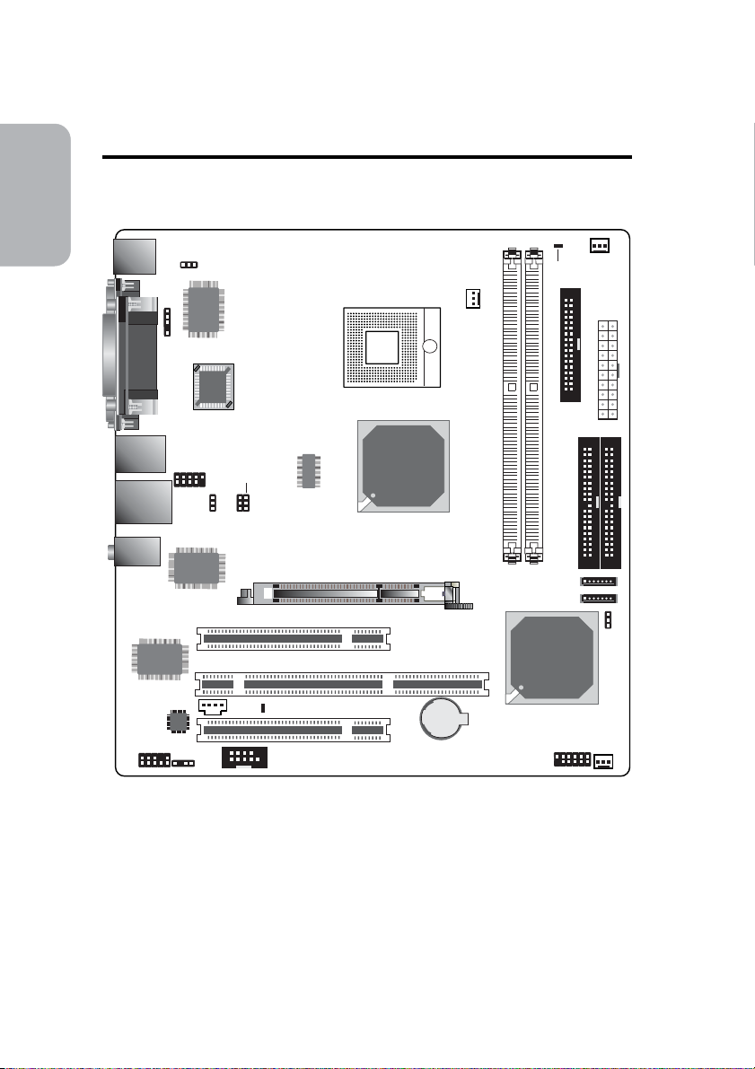
Chapter 1 - Quick Setup Guide
System Board Layout
Guide
Quick Setup
KB
Mouse
1394_2
USB 3-4
LAN
USB 1-2
Mic-in
Line-in
Line-out
COM 1
VGA
Realtek
RTL8110S
Parallel
IrDA
1
1
1394_1
1
VT6307
PS/2 power
select (JP2)
Winbond
BIOS
USB power
select (JP3)
VIA
W83627THF
1
1
J18
J3
1
CPU FSB
select (J3, J18)
IT8266R
AGP
PCI1Slot
PCI-X Slot 1
Intel
852GME
DDR 1 DDR 2
CPU fan
1
Socket
479
6300ESB
DIMM standby
power LED
SATA 2
SATA 1
Intel
FDD
1
2nd fan
ATX po we r
1
1
IDE 21IDE 1
1
1
1
Clear
CMOS
(JP10)
1
1
Front audio
Audio
codec
1
S/PDIF-out
1
1
CD-in
COM 2
PCI standby
power LED
PCI2Slot
Battery
Front panel
1
Chassis
fan
1
4
Jumpers
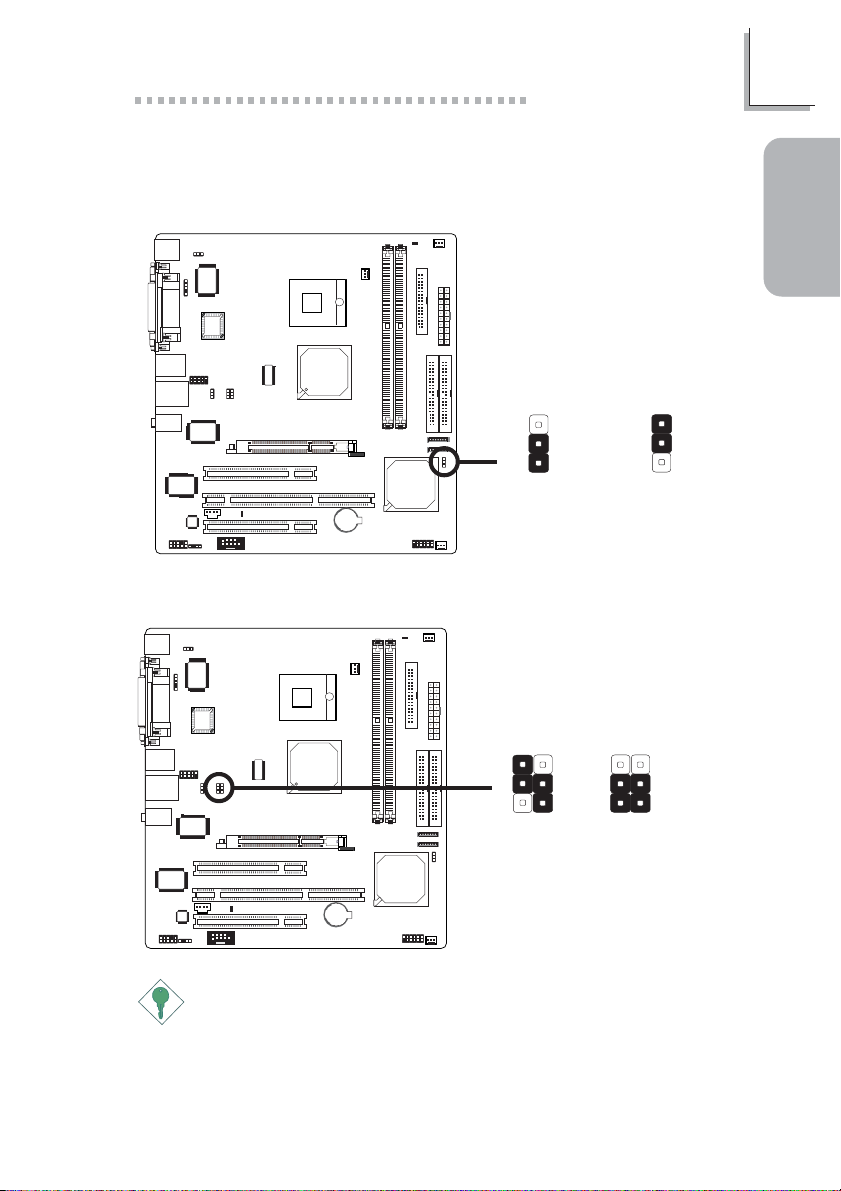
Clear CMOS Data
Quick Setup Guide
1
Guide
Quick Setup
3
JP10
X
1-2 On: Normal
2
1
(default)
CPU FSB Select
J3 J18 J3 J18
J3/J18
X
J3:1-2 On
J18: 2-3 On
Auto (default)
Important:
Overclocking may result to the CPU’s or system’s instability and are
not guaranteed to provide better system performance. If you are
unable to boot your system due to overclocking, make sure to set
these jumpers back to their default settings.
1
2
3
3
2
1
2-3 On:
Clear CMOS Data
1
2
3
2-3 On:
100MHz
5
1
Quick Setup Guide
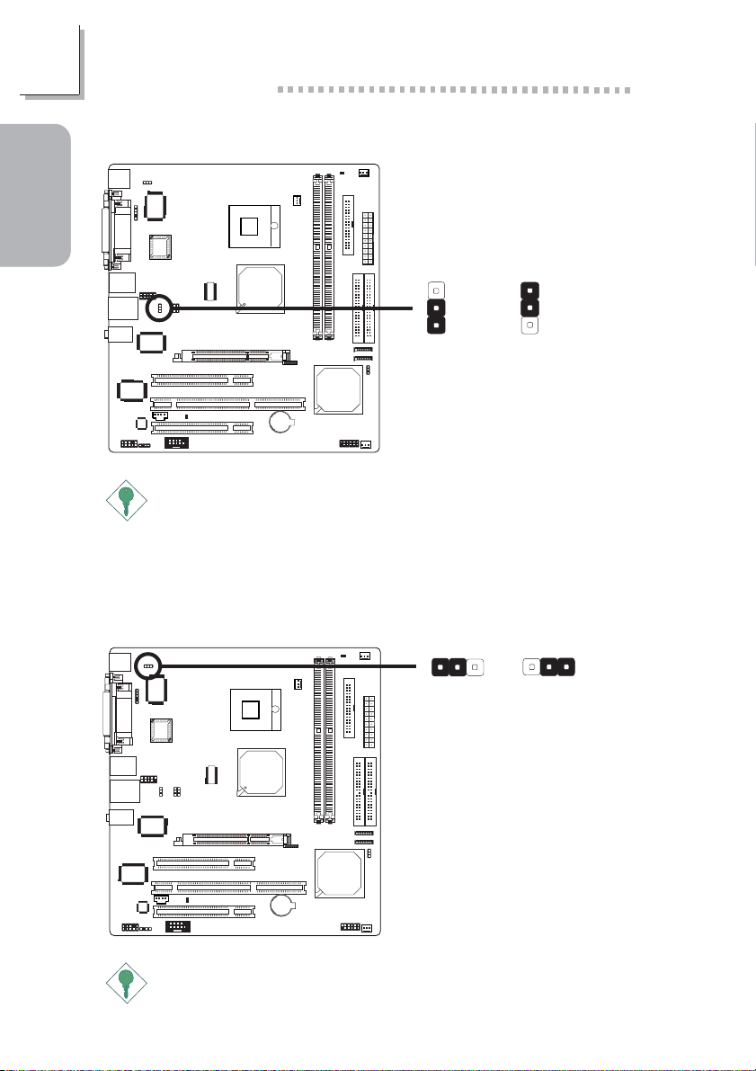
USB Power Select
Guide
Quick Setup
JP3
3
2
X
1
1-2 On: 5V
(default)
2-3 On: 5VSB
Important:
If you are using the Wake-On-USB Keyboard/Mouse function for 2
USB ports, the 5VSB power source of your power supply must
support ≥1.5A. For 3 or more USB ports, the 5VSB power source of
your power supply must support ≥2A.
PS/2 Power Select
JP2
X
312
1-2 On: 5V
(default)
2-3 On: 5VSB
3
2
1
312
Important:
The 5VSB power source of your power supply must support
≥
720mA.
6
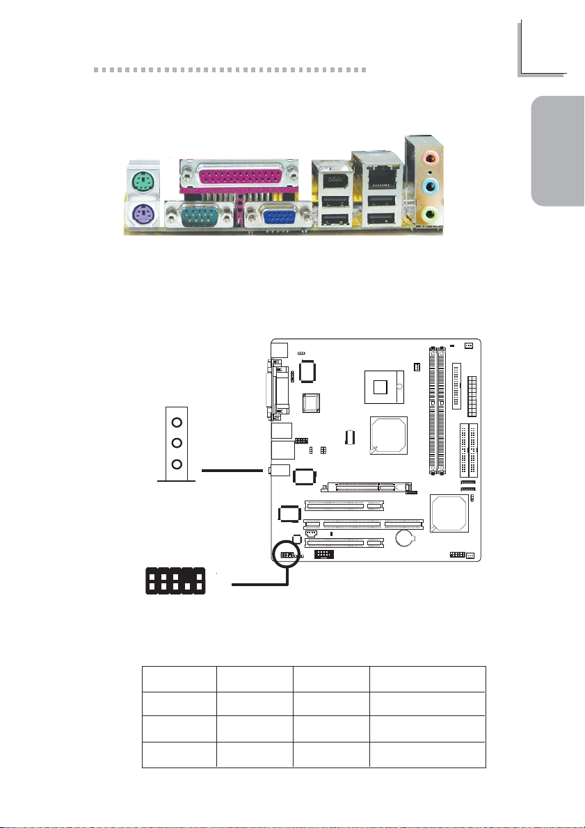
Rear Panel I/O Ports
Quick Setup Guide
1
PS/2
Mouse
COM 1 VGAPS/2 KB
Parallel
1394_2
USB 3-4 USB 1-2
I/O Connectors
Audio (Rear Audio and Front Audio)
Mic-in
Line-in
Line-out
Rear audio
W
LAN
Mic-in
Line-in
Line-out
Guide
Quick Setup
GND
2
1
Mic
Light Blue
Lime
Pink
AuD_Vcc
AuD_R_Return
AuD_L_Return
Key
10
N. C.
Mic Power
AuD_L_Out
AuD_R_Out
W
9
2-channel
Line-in
Line-out
Front
audio
Mic-in
4-channel
Rear R/L
Front R/L
Mic-in
6-channel
Rear R/L
Front R/L
Center/Subwoofer
7

1
Quick Setup Guide
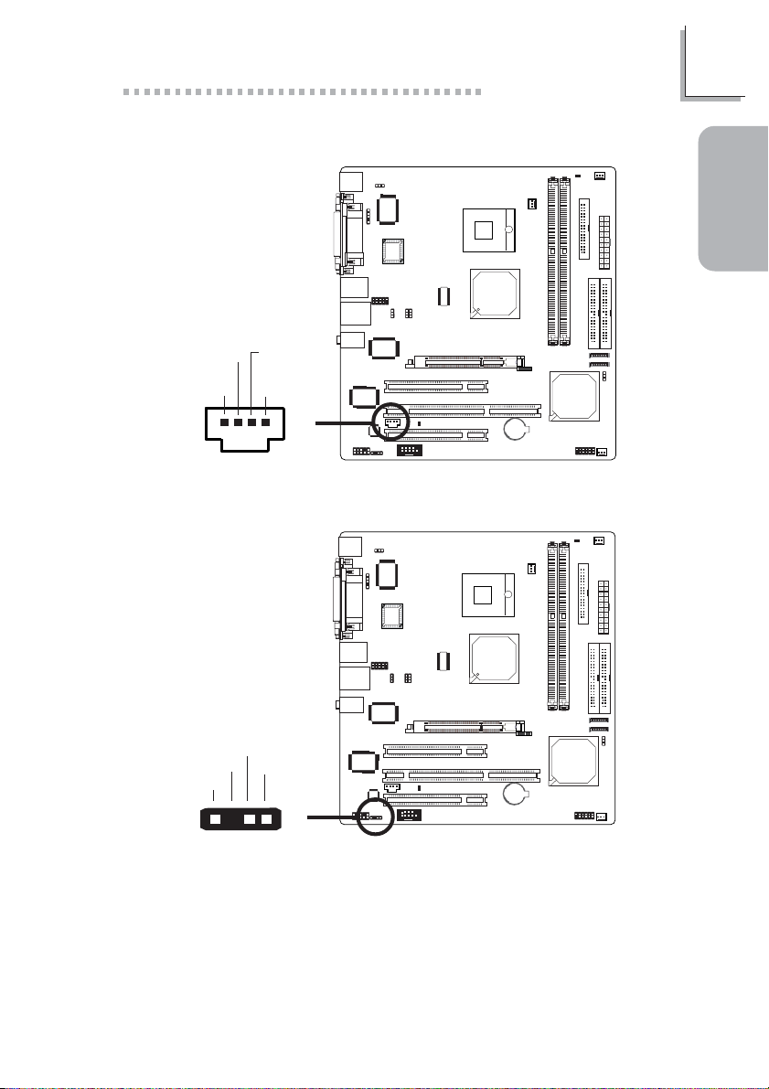
Serial Ports
Guide
Quick Setup
COM 2
IEEE 1394
COM 1
2
1
1394_2
RD
CD
DTR
DSR
TD
GND
CTS
RTS
RI
W
W
9
W
Ground
TPB-
+12V (fused)
TPA-
Ground
TPB+
Ground
+12V (fused)
10
Key
W
9
1394_1
2
1
TPA+
8
CD-in Internal Audio Connector
Ground Ground
Left audio
channel
Right audio
channel
Quick Setup Guide
1
Guide
Quick Setup
14
W
S/PDIF-out Connector
SPDIF out
Key
GND
+5V
1
4
W
9
1
Quick Setup Guide
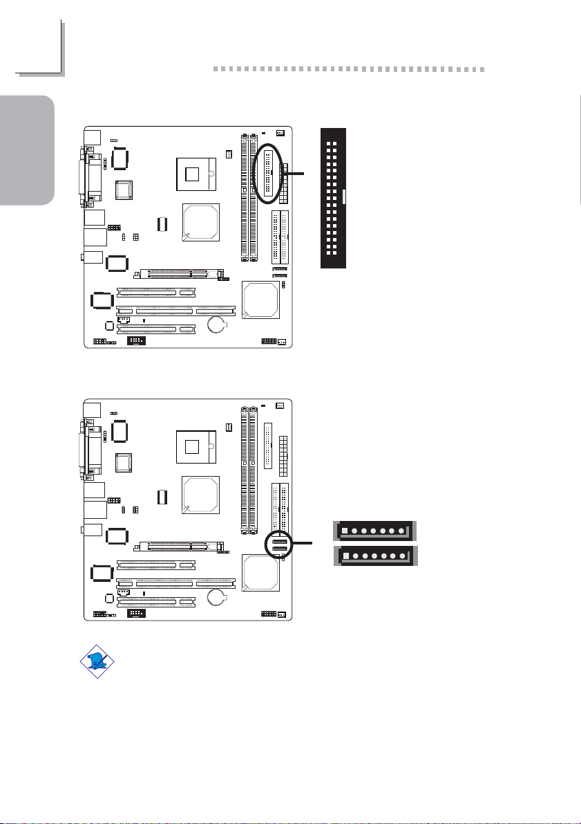
Floppy Disk Drive Connector
Guide
Quick Setup
Serial ATA Connectors
34
33
X
21
17
SATA 2 (J14)
X
17
SATA 1 (J15)
10
RXP
TXP
TXN
RXN
GND
GND
Note:
The Intel 6300ESB south bridge chip allows configuring RAID on
Serial ATA drives. It supports RAID 0 and RAID 1.
GND

IDE Disk Drive Connectors
Quick Setup Guide
1
IrDA Connector
IRTX
Ground
IRRX
N. C.
VCC
40
39
40
39
Guide
Quick Setup
X
21
5
W
1
21
IDE 1IDE 2
Note:
The sequence of the pin functions on some IR cable may be
reversed from the pin function defined on the system board. Make
sure to connect the cable connector to the IR connector according to
their pin functions.
11
1
Quick Setup Guide
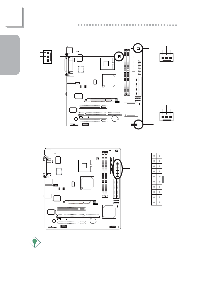
Cooling Fan Connectors
Sense
Power
Ground
Guide
Quick Setup
CPU fan
Power Connector
Power
Ground
3
X
1
X
X
10
+12V
5VSB
PW-OK
X
Ground
+5V
Ground
+5V
Ground
3.3V
3.3V
Sense
13
2nd fan
Power
Ground
Sense
13
Chassis fan
20
+5V
+5V
-5V
Ground
Ground
Ground
PS-ON
Ground
-12V
3.3V
111
12
Important:
To ensure that adequate power is provided, use a 250 Watt (or
greater) power supply.
 Loading...