

DFI 845PE-ML User Manual

845PE-ML
Re v . A+
System Board
User’s Manual
78200350

Copyright
This publication contains information that is protected by copyright. No part of it may be reproduced in any form or by any
means or used to make any transformation/adaptation without
the prior written permission from the copyright holders.
This publication is provided for informational purposes only. The
manufacturer makes no representations or warranties with respect to
the contents or use of this manual and specifically disclaims any
express or implied warranties of merchantability or fitness for any
par ticular pur pose. The user will assume the entire risk of the use or
the results of the use of this document. Further, the manufacturer
reser ves the right to revise this publication and make changes to its
contents at any time, without obligation to notify any person or
entity of such revisions or changes.
© 2004. All Rights Reser ved.
Trademarks
Windows® 98 SE, Windows® ME, Windows® 2000, Windows NT
®
4.0 and Windows® XP are registered trademarks of Microsoft
Corporation. Intel® and Pentium® 4 are registered trademarks of
Intel Corporation. Award is a registered trademark of Award Software, Inc. Other trademarks and registered trademarks of products appearing in this manual are the properties of their respective holders.
Caution
To avoid damage to the system:
• Use the correct AC input voltage range
..
..
.
To reduce the r isk of electric shock:
• Unplug the power cord before removing the system chassis
cover for installation or ser vicing. After installation or servicing,
cover the system chassis before plugging the power cord.

Battery:
• Danger of explosion if batter y incor rectly replaced.
• Replace only with the same or equivalent type recommend
by
the manufacturer.
• Dispose of used batteries according to the battery
manufacturer’s
instructions.
Joystick or MIDI por t:
• Do not use any joystick or MIDI device that requires more than
10A current at 5V DC. There is a risk of fire for devices that
exceed this limit.
FCC and DOC Statement on Class B
This equipment has been tested and found to comply with the limits
for a Class B digital device, pursuant to Part 15 of the FCC rules.
These limits are designed to provide reasonable protection against
harmful interference when the equipment is operated in a residential
installation. This equipment generates, uses and can radiate radio
frequency energy and, if not installed and used in accordance with
the instruction manual, may cause harmful interference to radio
communications. However, there is no guarantee that interference
will not occur in a par ticular installation. If this equipment does cause
harmful interference to radio or television reception, which can be
determined by turning the equipment off and on, the user is
encouraged to try to correct the interference by one or more of the
following measures:
• Reorient or relocate the receiving antenna.
• Increase the separation between the equipment and the receiver.
• Connect the equipment into an outlet on a circuit different from
that to which the receiver is connected.
• Consult the dealer or an experienced radio TV technician for
help.
Notice:
1. The changes or modifications not expressly approved by the
par ty responsible for compliance could void the user's authority
to operate the equipment.
2. Shielded interface cables must be used in order to comply with
the emission limits.

4
Introduction
1
80
83
91
94
Table of Contents
Chapter 1 - Introduction
1.1 Features and Specifications.................................................................................
1.2 Hyper-Threading Technology Functionality Requirements...
1.3 Package Checklist...........................................................................................................
Chapter 2 - Hardware Installation
2.1 System Board Layout ............................................................................................
2.2 System Memor y.............................................................................................................
2.3 CPU..............................................................................................................................................
2.4 Jumper Settings...............................................................................................................
2.5 Rear Panel I/O Por ts................................................................................................
2.6 I/O Connectors.............................................................................................................
Chapter 3 - BIOS Setup
3.1 Award BIOS Setup Utility....................................................................................
3.2 Updating the BIOS.....................................................................................................
Chapter 4 - Supported Softwares
4.1 Desktop Management Interface....................................................................
4.2 Drivers, Utilities and Software Applications....................................
4.3 3D Audio Configuration.........................................................................................
4.4 Installation Notes...........................................................................................................
7
12
12
43
78
13
14
16
21
24
34

5
1
Introduction
95
95
Appendix A - Enabling the Hyper-Threading
Technology
A.1 Enabling the Hyper-Threading Technology.........................................
Appendix B - System Error Messages
B.1 POST Beep............................................................................................................................
B.2 Error Messages..................................................................................................................
Appendix C - Troubleshooting
C .1 Troubleshooting Checklist....................................................................................
97
92

6
Introduction
1
1.1 Features and Specifications
1.1.1 Features
Chipset
• Intel® 845PE chipset
- Intel® 82845PE Memory Controller Hub (MCH)
- Intel® 82801DB I/O Controller Hub (ICH4)
Processor
The system board is equipped with Socket 478 for installing one
of the following suppor ted processor s.
• Intel® Pentium® 4 (Prescott and Northwood) processor up to
3.06GHz
- Intel Hyper-Threading Technology
- FSB: 400MHz and 533MHz
• Intel® Celeron® processor
- 400MHz system data bus
System Memory
• Two 184-pin DDR SDRAM DIMM sockets
• Supports 2.5V unbuffered PC1600 (DDR200), PC2100
(DDR266) and PC2700 (DDR333) DDR SDRAM DIMM
• Supports maximum of 2GB system memory using 64Mbit,
128Mbit, 256Mbit or 512Mbit technology
- Double-sided x16 DDR SDRAM DIMM is not suppor ted
Chapter 1 - Introduction
Density Width
Single/Double
184-pin DDR
64 Mbit
X8
SS/DS
64/128MB
X16
SS/DS
32MB/NA
Density
128 Mbit
X8
SS/DS
128/256MB
X16
SS/DS
64MB/NA
256 Mbit
X8
SS/DS
256/512MB
X16
SS/DS
128MB/NA
512 Mbit
X8
SS/DS
512/1024MB
X16
SS/DS
256MB/NA

7
1
Introduction
Expansion Slots
• 1 AGP slot
• 3 PCI slots
AGP
The AGP slot only supports 1.5V AGP 4x (1066MB/sec. bandwidth) add-in cards. AGP is an interface designed to support high
performance 3D graphics cards for 3D graphics applications. It
handles large amounts of graphics data with the following features:
• Pipelined memory read and write operations that hide
memory access latency.
• Demultiplexing of address and data on the bus for nearly 100
percent efficiency.
Onboard Audio Features
• 20-bit stereo full-duplex codec with independent variable sampling rate
• High quality differential CD input
• True stereo line level outputs
• 6-channel audio output via software
6-Channel Audio Output via Software
The audio jacks at the rear panel will support 6-channel audio
only when the audio utility is configured to support this function.
The mic-in at the rear will be disabled. Use the front audio’s micin jack.
Onboard LAN Features
• Uses Realtek RTL8101L fast ethernet controller
• Integrated IEEE 802.3, 10BASE-T and 100BASE-TX compatible
PHY
• 32-bit PCI master interface
• Integrated power management functions
• Full duplex suppor t at both 10 and 100 Mbps
• Suppor ts IEEE 802.3u auto-negotiation
• Supports wire for management

8
Introduction
1
PCI Bus Master IDE Controller
• Two PCI IDE interfaces suppor t up to four IDE devices
• Supports ATA/33, ATA/66 and ATA/100 hard drives
• PIO Mode 4 Enhanced IDE (data transfer rate up to 14MB/
sec.)
• Bus mastering reduces CPU utilization during disk transfer
• Suppor ts ATAPI CD-ROM, LS-120 and ZIP
IrDA Interface
The system board is equipped with an IrDA connector for wireless
connectivity between your computer and peripheral devices. The
IRDA (Infrared Data Association) specification supports data
transfers of 115K baud at a distance of 1 meter.
USB Ports
The system board supports USB 2.0 and USB 1.1 ports. USB 1.1
suppor ts 12Mb/second bandwidth while USB 2.0 suppor ts 480Mb/
second bandwidth providing a marked improvement in device
transfer speeds between your computer and a wide range of
simultaneously accessible external Plug and Play peripherals.
BIOS
• Award BIOS, Windows® 98SE/2000/ME/XP Plug and Play
compatible
• Suppor ts SCSI sequential boot-up
• Supports DMI 2.0 function
• 2Mbit flash memory
Desktop Management Interface (DMI)
The system board comes with a DMI 2.0 built into the BIOS. The
DMI utility in the BIOS automatically records various information
about your system configuration and stores these information in
the DMI pool, which is a part of the system board's Plug and Play
BIOS. DMI, along with the appropriately networked software, is
designed to make inventory, maintenance and troubleshooting of
computer systems easier. Refer to chapter 4 for instructions on
using the DMI utility.

9
1
Introduction
Compatibility
• PCI 2.2 and AC ’97 compliant
Rear Panel I/O Ports (PC 99 color-coded connectors)
• One mini-DIN-6 PS/2 mouse port
• One mini-DIN-6 PS/2 keyboard port
• One RJ45 LAN port
• Two USB 2.0/1.1 por ts
• Two DB-9 serial por ts
• One DB-25 parallel por t
• One game/MIDI port
• Three audio jacks: line-out, line-in and mic-in
I/O Connectors
• Two connector s for 4 additional external USB 2.0/1.1 por ts
• One front audio connector for external line-out and mic-in jacks
• One CD-in internal audio connector
• One connector for IrDA interface
• Two IDE connector s
• One floppy connector
• Two ATX power supply connectors
• Two fan connectors
1.1.2 Intelligence
Dual Function Power Button
Depending on the setting in the “Soft-Off By PWR-BTTN” field of
the Power Management Setup, this switch will allow the system to
enter the Soft-Off or Suspend mode.

10
Introduction
1
Wake-On-Ring
This feature allows the system that is in the Suspend mode or
Soft Power Off mode to wake-up/power-on to respond to calls
coming from an external modem or respond to calls from a
modem PCI card that uses the PCI PME (Power Management
Event) signal to remotely wake up the PC.
Important:
If you are using a modem add-in card, the 5VSB power source
of your power supply must support ≥720mA.
Wake-On-LAN
This feature allows the network to remotely wake up a Soft
Power Down (Soft-Off) PC. It is supported via the onboard LAN
port or via a PCI LAN card that uses the PCI PME (Power Management Event) signal. However, if your system is in the Suspend
mode, you can power-on the system only through an IRQ or
DMA interr upt.
Important:
The 5VSB power source of your power supply must support
≥
720mA.
Wake-On-PS/2 Keyboard/Mouse
This function allows you to use the PS/2 keyboard or PS/2
mouse to power-on the system.
Important:
The 5VSB power source of your power supply must support
≥
720mA.

11
1
Introduction
Wake-On-USB Keyboard/Mouse
The Wake-On-USB Keyboard/Mouse function allows you to use a
USB keyboard or USB mouse to wake up a system from the S3
(STR - Suspend To RAM) state.
Important:
• If you are using the Wake-On-USB Keyboard/Mouse function for 2 USB ports, the 5VSB power source of your power
supply must support ≥1.5A.
• If you are using the Wake-On-USB Keyboard/Mouse function for 3 or more USB ports, the 5VSB power source of
your power supply must support ≥2A.
RTC Timer to Power-on the System
The RTC installed on the system board allows your system to
automatically power-on on the set date and time.
ACPI
The system board is designed to meet the ACPI (Advanced Configuration and Power Interface) specification. ACPI has energy saving features that enables PCs to implement Power Management
and Plug-and-Play with operating systems that support OS Direct
Power Management. Currently, only Windows
®®
®®
®
98SE/2000/ME/XP
supports the ACPI function. ACPI when enabled in the Power
Management Setup will allow you to use the Suspend to RAM
function.
With the Suspend to RAM function enabled, you can power-off the
system at once by pressing the power button or selecting “Standby”
when you shut down Windows
®®
®®
®
98SE/2000/ME/XP without having to go through the sometimes tiresome process of closing
files, applications and operating system. This is because the system
is capable of storing all programs and data files during the entire
operating session into RAM (Random Access Memory) when it
powers-off. The operating session will resume exactly where you
left off the next time you power-on the system.
Important:
The 5VSB power source of your power supply must support
≥
1A.

12
Introduction
1
AC Power Failure Recovery
When power returns after an AC power failure, you may choose
to either power-on the system manually, let the system power-on
automatically or return to the state where you left off before
power failure occurs.
Virus Protection
Most viruses today destroy data stored in hard drives. The system
board is designed to protect the boot sector and partition table
of your hard disk drive.
1.2 Hyper-Threading Technology Functionality
Requirements
Enabling the functionality of Hyper-Threading Technology for your
computer system requires ALL of the following platforms.
Components:
• CPU - an Intel® Pentium® 4 Processor with HT Technology
• Chipset - an Intel® chipset that suppor ts HT Technology
• BIOS - a BIOS that suppor ts HT Technology and has it enabled
• OS - an operating system that includes optimizations for HT
Technology
Please refer to Appendix A for information about enabling the
functionality of the Hyper-Threading Technology. For more information on Hyper-Threading Technology, go to: www.intel.com/
info/hyperthreading.
1.3 Package Checklist
The system board package contains the following items:
! The system board
! A user’s manual
! One IDE cable for ATA/33/66/100 IDE drives
! One 34-pin floppy disk drive cable
! One “Mainboard Utility” CD
If any of these items are missing or damaged, please contact your
dealer or sales representative for assistance.
13
2
Hardware Installation
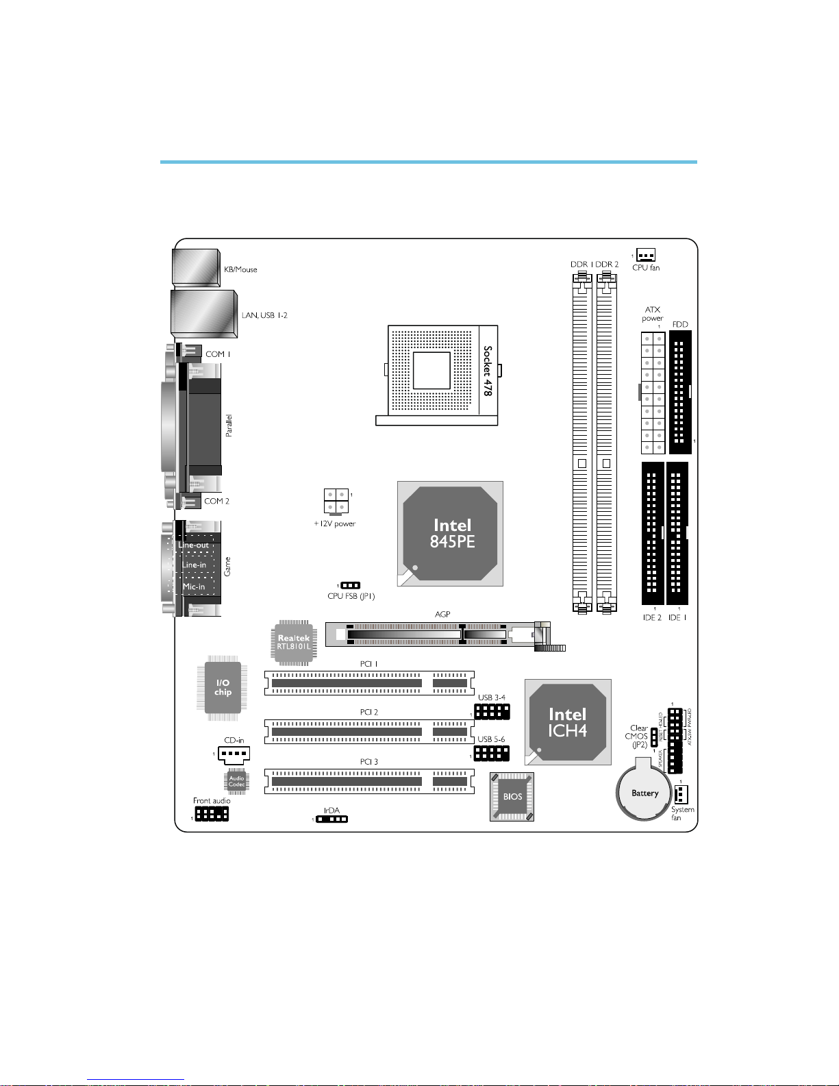
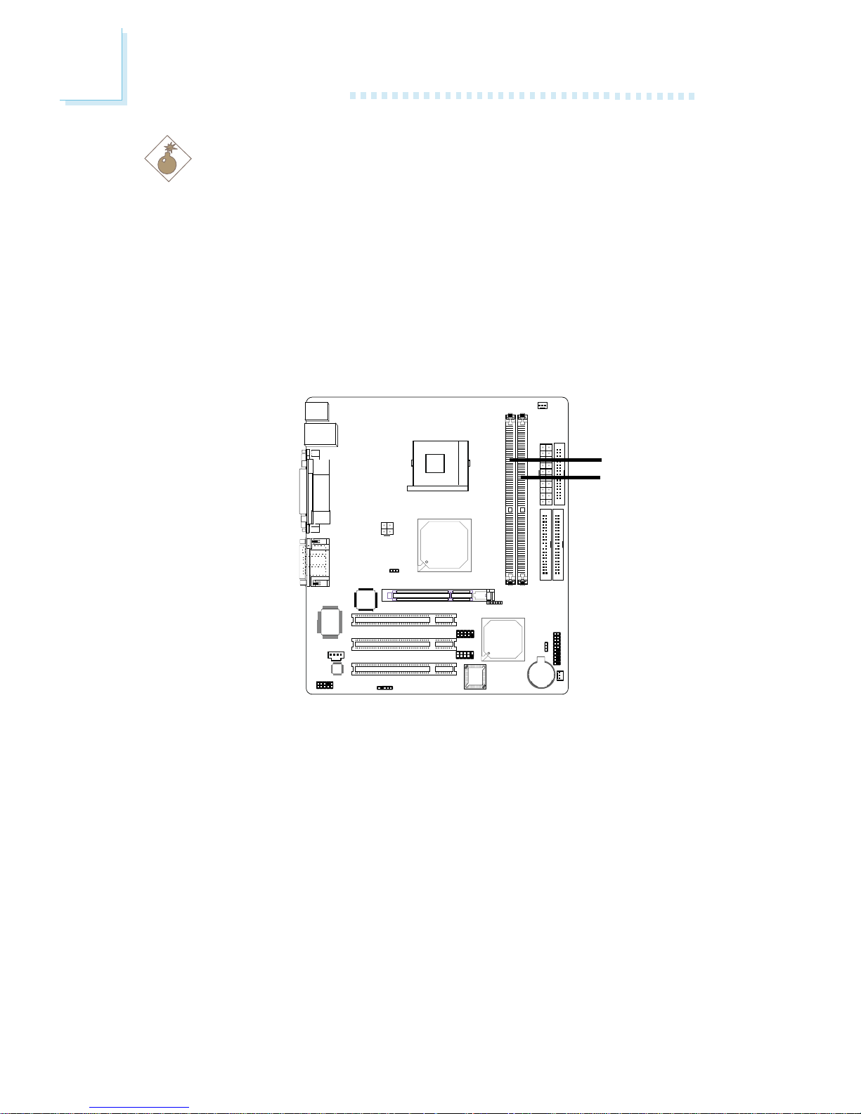
2.1 System Board Layout
Chapter 2 - Hardware Installation
14
2
Hardware Installation
2.2 System Memory
Warning:
Electrostatic discharge (ESD) can damage your system board, processor, disk drives, add-in boards, and other components. Perform the
upgrade instruction procedures described at an ESD workstation only.
If such a station is not available, you can provide some ESD protection
by wearing an antistatic wrist strap and attaching it to a metal part
of the system chassis. If a wrist strap is unavailable, establish and
maintain contact with the system chassis throughout any procedures
requiring ESD protection.
The system board is equipped with two 184-pin DDR SDRAM
DIMM (Dual In-line Memory Module) sockets that support 2.5V
DDR SDRAM DIMM. Double Data Rate SDRAM (DDR SDRAM)
is a type of SDRAM that doubles the data rate through reading
and writing at both the rising and falling edge of each clock. This
effectively doubles the speed of operation therefore doubling the
speed of data transfer.
Refer to chapter 1 (System Memory section) for detailed specification of the memory supported by the system board.
BIOS Setting
Configure the system memory in the Advanced Chipset Features
submenu of the BIOS.
.
.
.
.
.
.
.
.
DDR 1
DDR 2
15
2
Hardware Installation
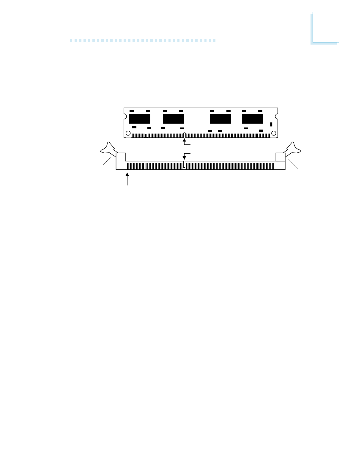
2.2.1 Installing the DIM Module
A DIM module simply snaps into a DIMM socket on the system
board. Pin 1 of the DIM module must correspond with Pin 1 of
the socket.
1. Pull the “tabs” which are at the ends of the socket to the
side.
2. Position the DIMM above the socket with the “notch” in the
module aligned with the “key” on the socket.
3. Seat the module vertically into the socket. Make sure it is
completely seated. The tabs will hold the DIMM in place.
Pin 1
Notch
Key
Tab
Tab
16
2
Hardware Installation
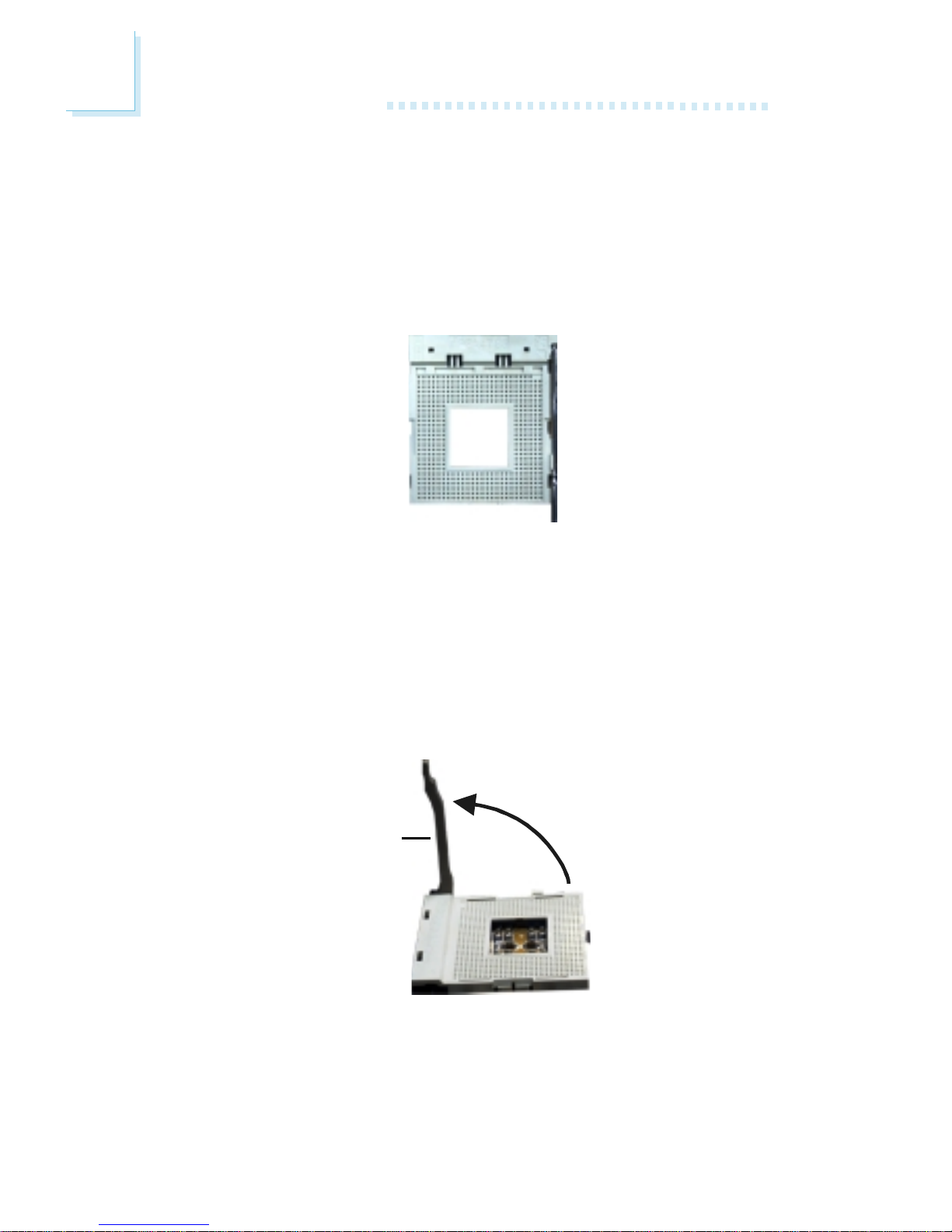
2.3 CPU
2.3.1 Overview
The system board is equipped with a surface mount 478-pin CPU
socket. This socket is exclusively designed for installing an Intel
processor.
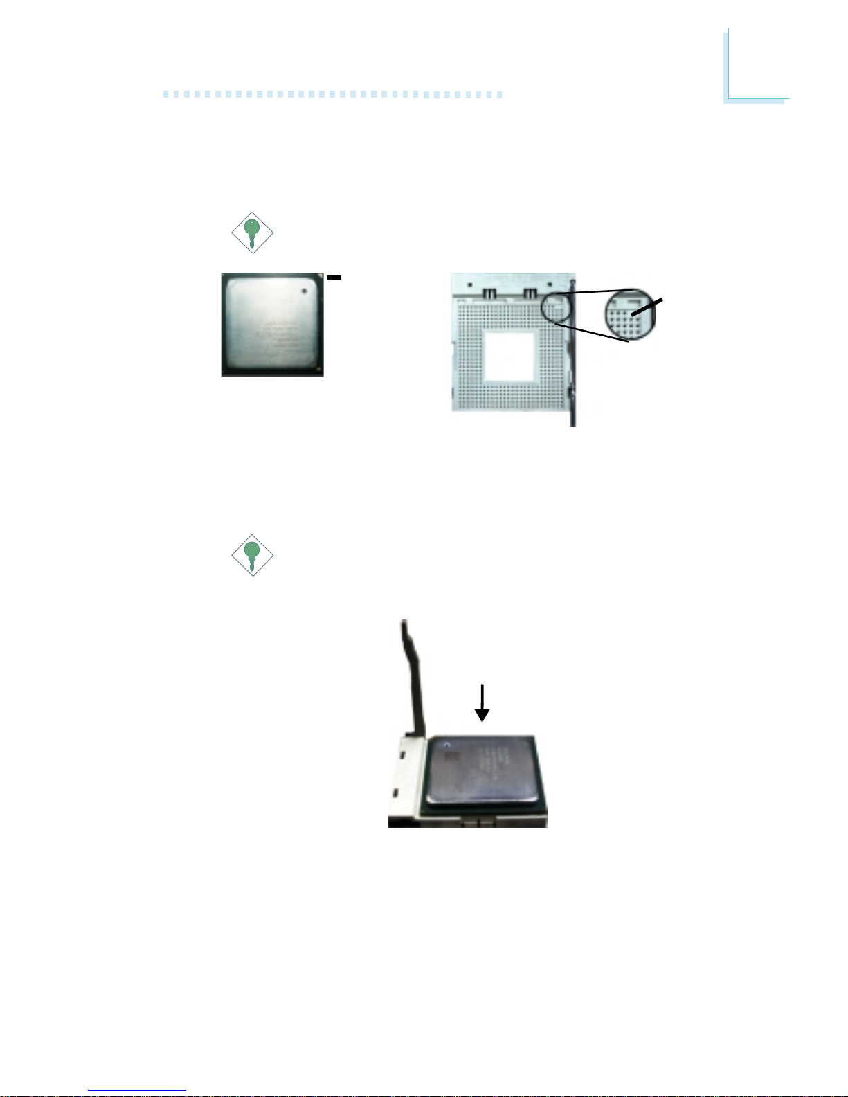
2.3.2 Installing the CPU
1. Locate Socket 478 on the system board.
2. Unlock the socket by pushing the lever sideways, away from the
socket, then lifting it up to a 90o angle. Make sure the socket is
lifted to at least this angle otherwise the CPU will not fit in
properly.
Lever
17
2
Hardware Installation
3. Position the CPU above the socket then align the gold mark
on the corner of the CPU (designated as pin 1) with pin 1 of
the socket.
Important:
Handle the CPU by its edges and avoid touching the pins.
Gold mark
4. Insert the CPU into the socket until it is seated in place. The
CPU will fit in only one orientation and can easily be inserted
without exerting any force.
Important:
Do not force the CPU into the socket. Forcing the CPU into
the socket may bend the pins and damage the CPU.
Pin 1

18
2
Hardware Installation
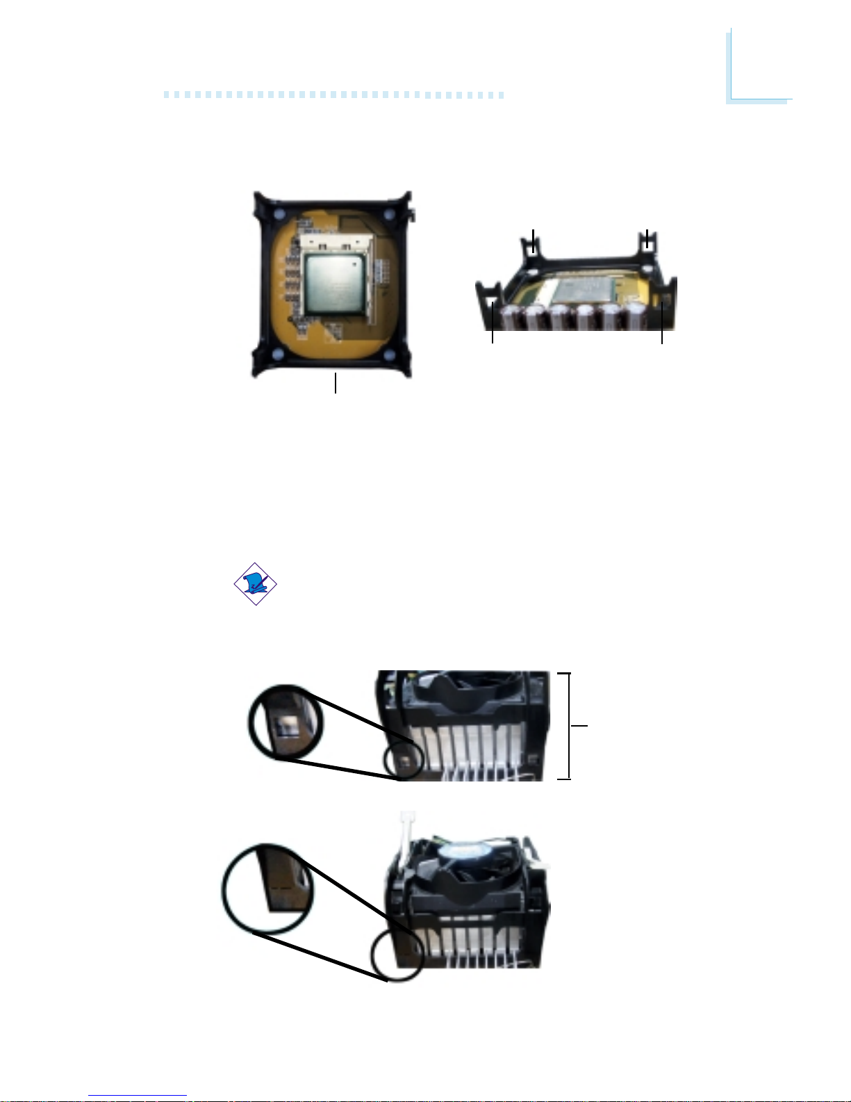
5. Once the CPU is in place, push down the lever to lock the
socket. The lever should click on the side tab to indicate that
the CPU is completely secured in the socket.
2.3.3 Installing the Fan and Heat Sink
The CPU must be kept cool by using a CPU fan with heatsink.
Without sufficient air circulation across the CPU and heat sink,
the CPU will overheat damaging both the CPU and system board.
Note:
• Only use Intel® certified fan and heat sink.
• An Intel® boxed processor package contains a retention
mechanism, heat sink, fan and installation guide. If the installation procedure in the installation guide differs from the one
in this section, please follow the installation guide in the
package.
• If you are installing a non-boxed processor, the heat sink, fan
and retention mechanism assembly may look different from
the one shown in this section but the procedure will more or
less be the same.
19
2
Hardware Installation
1. The system board comes with the retention module base already installed.
Retention
module base
Retention
hole
Retention
hole
Retention
hole
Retention
hole
2. Position the fan / heat sink and retention mechanism assembly
on the CPU, then align and snap the retention legs’ hooks to
the retention holes at the 4 corners of the retention module
base.
Note:
You will not be able to snap the hooks into the holes if the
fan / heat sink and retention mechanism assembly did not
fit properly onto the CPU and retention module base.
Unsnapped
Fan / heat sink
and retention
mechanism
assembly
Snapped
20
2
Hardware Installation
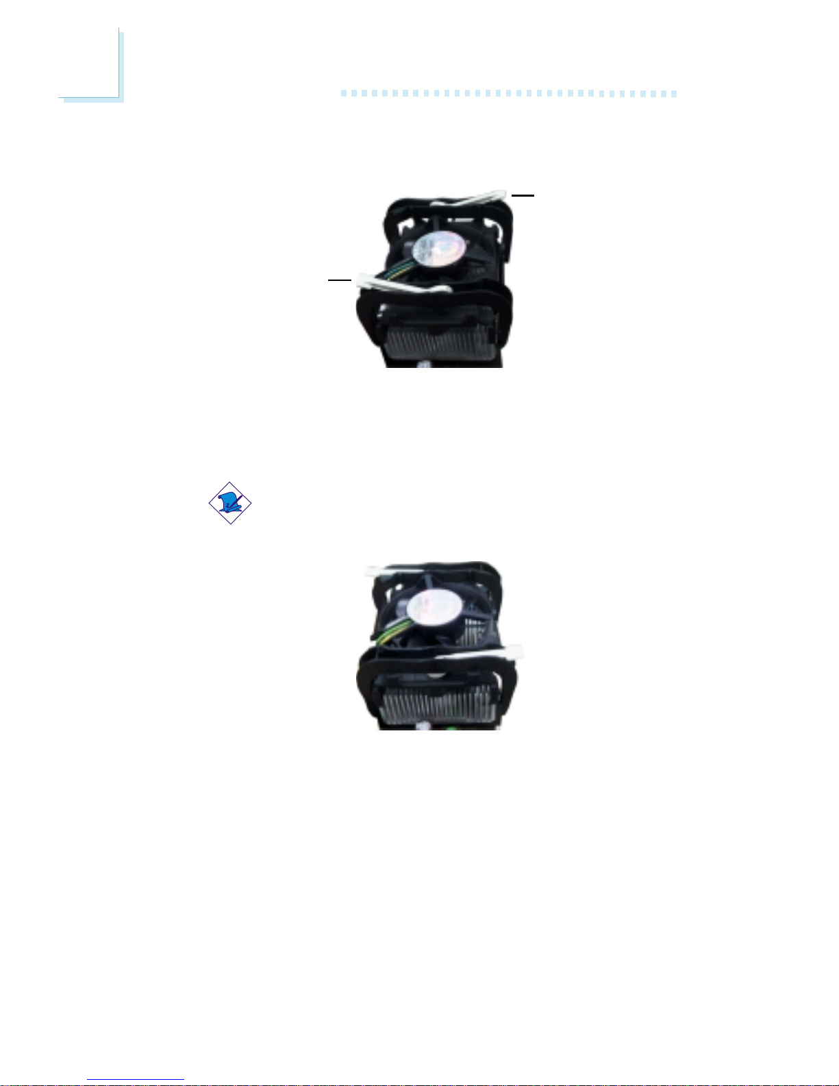
3. The retention levers at this time remains unlocked as shown
in the illustration below.
Retention lever
Retention lever
4. Move the retention levers to their opposite directions then
push them down. This will secure the fan / heat sink and retention mechanism assembly to the retention module base.
Note:
You will not be able to push the lever down if the direction
is incorrect.
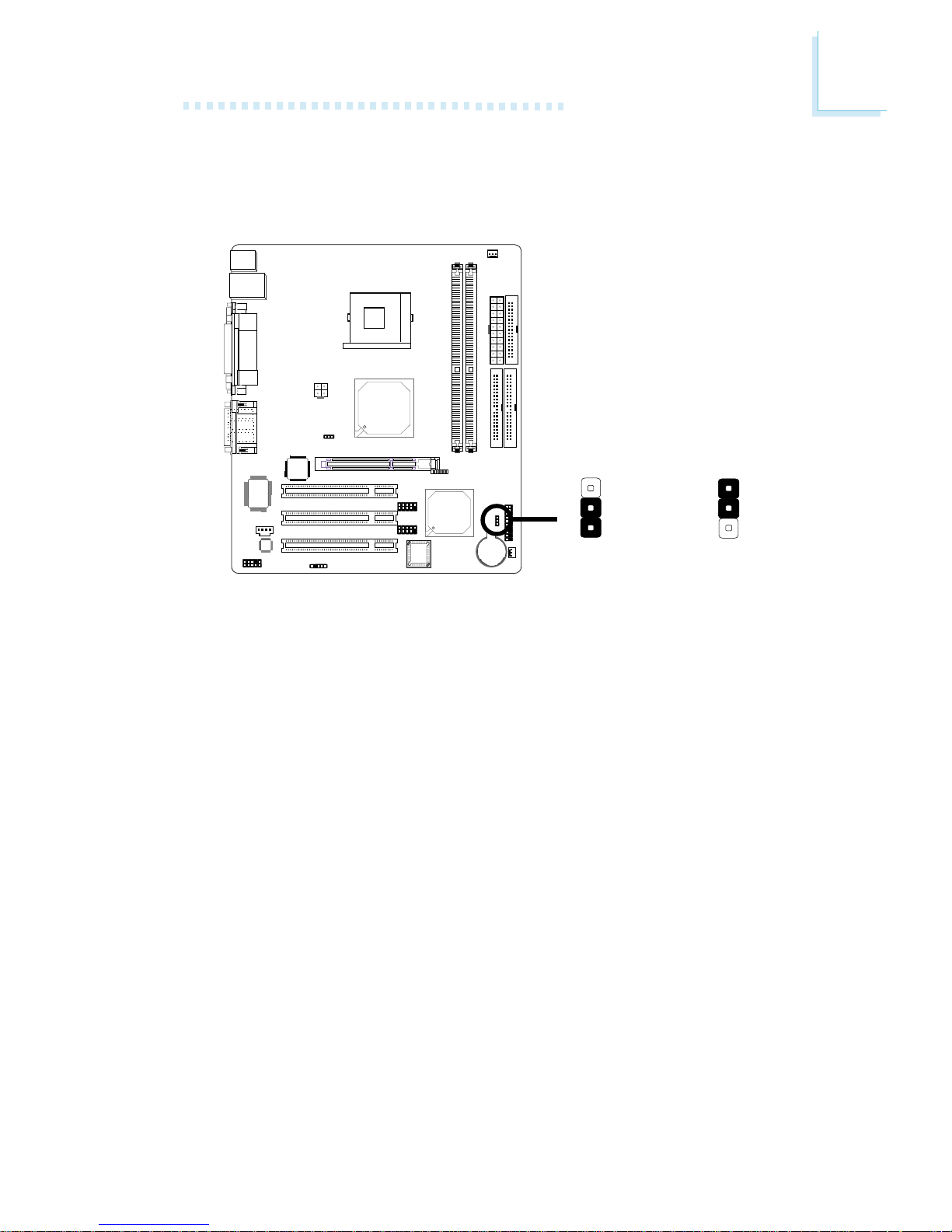
5. Connect the CPU fan’s cable connector to the CPU fan connector on the system board.
21
2
Hardware Installation
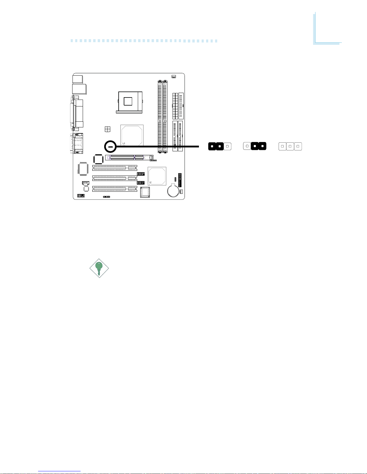
2.4.1 Jumper Settings for Clearing CMOS Data
If you encounter the following,
a) CMOS data becomes corrupted.
b) You for got the supervisor or user password.
c) You are unable to boot-up the computer system because the proc-
essor’s ratio/clock was incorrectly set in the BIOS.
you can reconfigure the system with the default values stored in
the ROM BIOS.
To load the default values stored in the ROM BIOS, please follow
the steps below.
1. Power-off the system.
2. Set JP2 pins 2 and 3 to On. Wait for a few seconds and set
JP2 back to its default setting, pins 1 and 2 On.
3. Now power-on the system.
If your reason for clearing the CMOS data is due to incorrect
setting of the processor’s ratio/clock in the BIOS, please proceed to step 4.
2-3 On:
Clear CMOS Data
1-2 On: Normal
(default)
!
JP2
2.4 Jumper Settings
3
1
2
3
1
2

22
2
Hardware Installation
4. After powering-on the system, press <Del> to enter the main
menu of the BIOS.
5. Select the Frequency/Voltage Control submenu and press
<Enter>.
6. Set the “CPU Clock Ratio” or “CPU Clock” field to its default
setting or an appropriate frequency ratio or bus clock. Refer
to the Frequency/Voltage Control section in chapter 3 for
more information.
7. Press <Esc> to return to the main menu of the BIOS setup
utility. Select “Save & Exit Setup” and press <Enter>.
8. Type <Y> and press <Enter>.
23
2
Hardware Installation
2.4.2 Jumper Settings for Selecting the CPU’s FSB
JP1’s default setting is Auto. The system will run according to the
front side bus of the CPU installed on the system board. You can
also set the FSB fixed at 100MHz or 200MHz by setting JP1 to
2-3 On or All Off.
Important:
• If you are using a CPU whose frequency has been locked
by the manufacturer, overclocking will have no effect.
• Overclocking may result to the CPU’s or system’s instability
and are not guaranteed to provide better system performance. If you are unable to boot your system due to
overclocking, make sure to set this jumper back to its default setting.
2-3 On:
100MHz
All Off:
200MHz
!
JP1
1-2 On: Auto
(default)
312
312
312
24
2
Hardware Installation
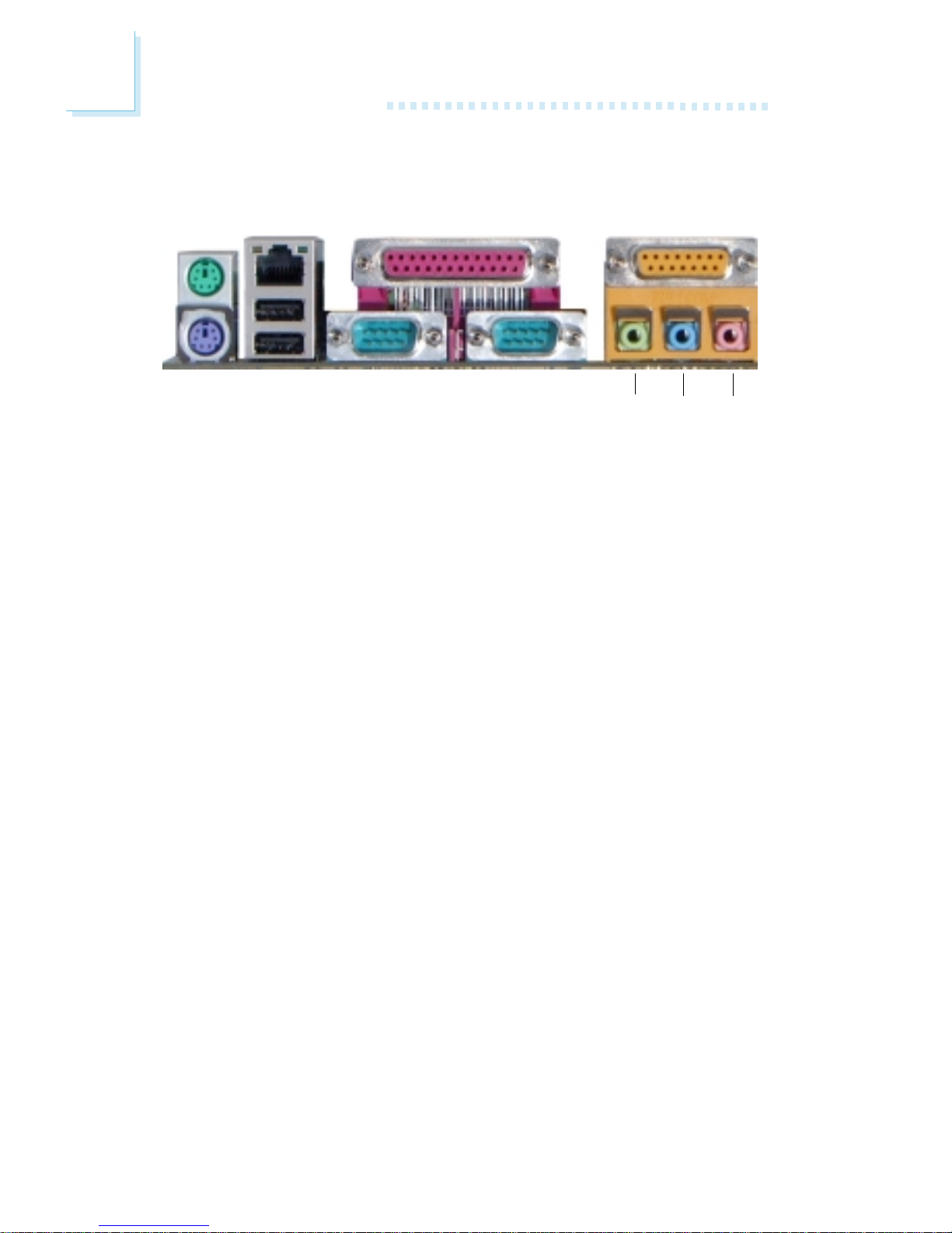
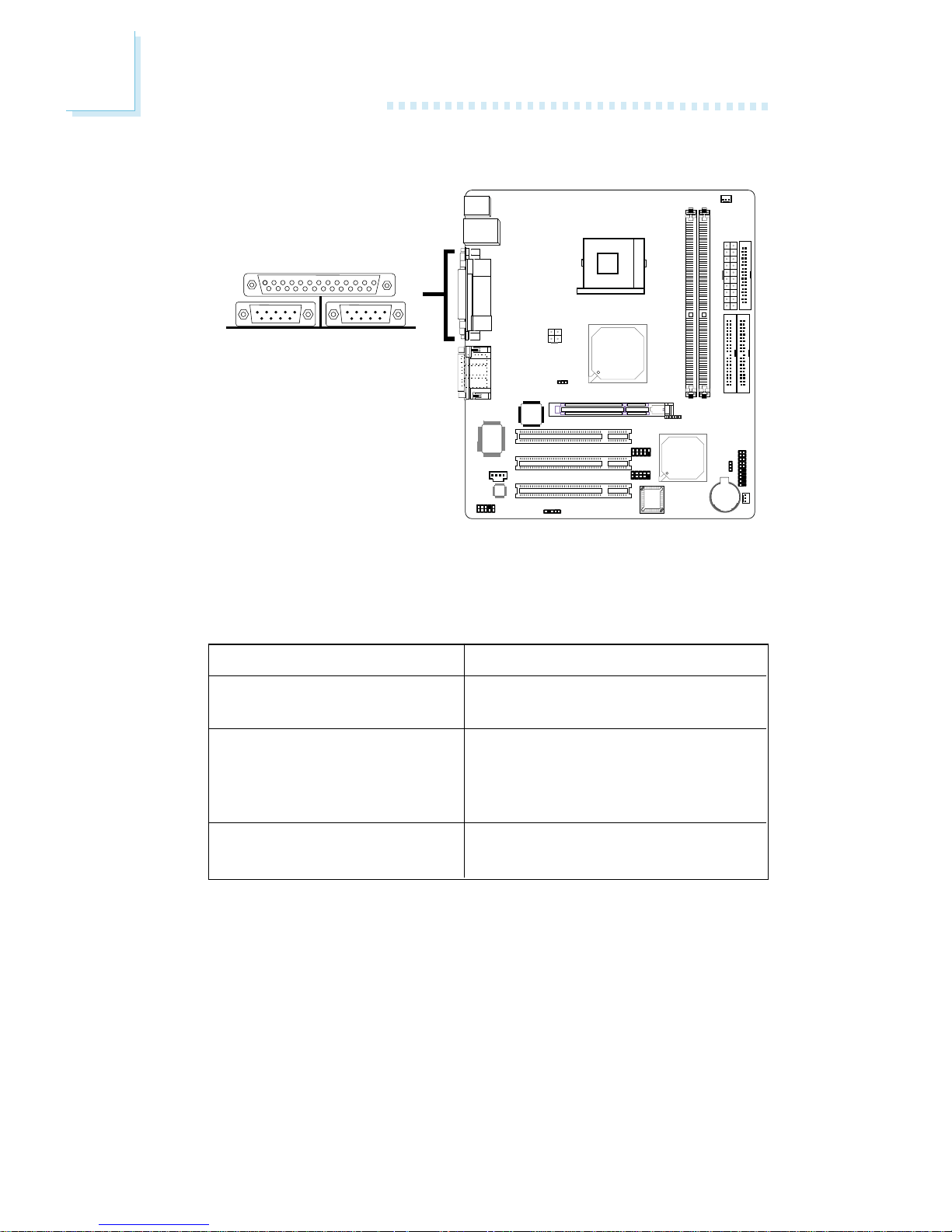
2.5 Rear Panel I/O Ports
The rear panel I/O ports consist of the following:
• PS/2 mouse port
• PS/2 keyboard port
• LAN port
• USB ports
• Parallel port
• COM ports
• Game port
• Line-out jack
• Line-in jack
• Mic-in jack
PS/2
Mouse
PS/2
K/B
RJ45
LAN
USB 1-2
COM 1
Parallel GAME/MIDI
Line-
out
Line-inMic-
in
COM 2

25
2
Hardware Installation
2.5.1 PS/2 Mouse and PS/2 Keyboard Ports
The system board is equipped with an onboard PS/2 mouse
(Green) and PS/2 keyboard (Purple) ports - both at location
CN1 of the system board. The PS/2 mouse port uses IRQ12. If a
mouse is not connected to this port, the system will reserve
IRQ12 for other expansion cards.
Warning:
Make sure to turn off your computer prior to connecting or
disconnecting a mouse or keyboard. Failure to do so may damage the system board.
Wake-On-PS/2 Keyboard/Mouse
The Wake-On-PS/2 Keyboard/Mouse function allows you to use
the PS/2 keyboard or PS/2 mouse to power-on the system. To
use this function:
• BIOS Setting:
Configure the PS/2 wake up function in the Integrated Peripherals submenu of the BIOS. Refer to chapter 3 for more information.
Important:
The 5VSB power source of your power supply must support
≥
720mA.
PS/2 Mouse
PS/2 Keyboard
.
.
.
.
.
.
.
.
"

26
2
Hardware Installation
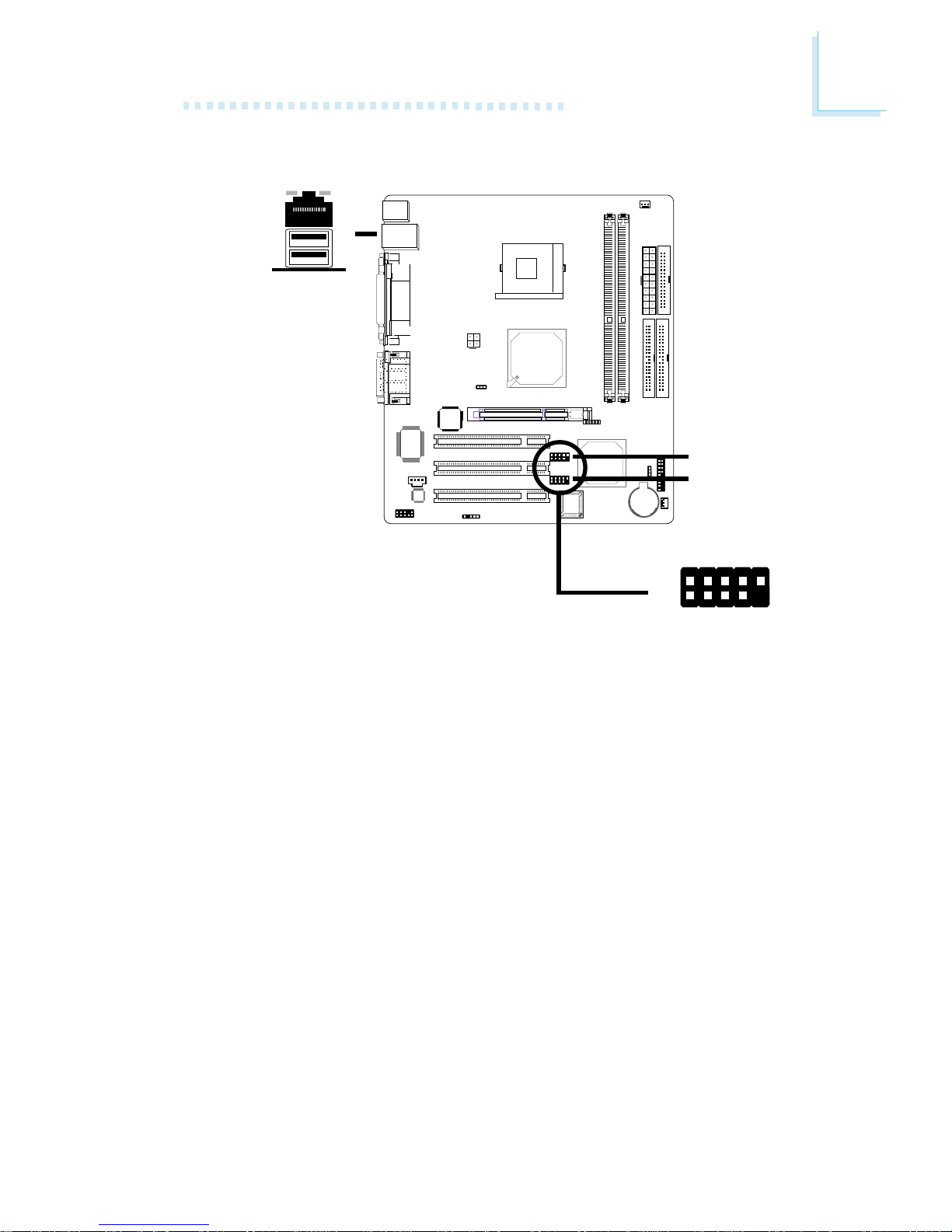
2.5.2 RJ45 Fast-Ethernet Port
The system board is equipped with an onboard RJ45 fastethernet LAN port at location CN7 of the system board. It allows the system board to connect to a local area network by
means of a network hub.
BIOS Setting
Enable or disable the onboard LAN in the Integrated Peripherals
submenu of the BIOS. Refer to chapter 3 for more information.
Driver Installation
Install the “LAN Drivers”. Refer to chapter 4 for more information.
RJ45 LAN
"
27
2
Hardware Installation
2.5.3 Universal Serial Bus Ports
USB 2
USB 1
"
Two onboard USB ports (Black) are at location CN7 of the system board.
The J6 (USB 3-4) and J7 (USB 5-6) connectors allow you to
connect 4 additional USB ports. The additional USB por ts may be
mounted on a card-edge bracket. Install the card-edge bracket to
the system chassis then inser t the cable connector to J6 or J7.
BIOS Setting
Configure the onboard USB in the Integrated Peripherals
submenu of the BIOS. Refer to chapter 3 for more information.
USB 3-4
USB 5-6
1
VCC
-Data
+Data
Ground
Key
VCC
-Data
+Data
Ground
N. C .
2
10
9
"

28
2
Hardware Installation
Driver Installation
You may need to install the proper drivers in your operating
system to use the USB device. Refer to your operating system’s
manual or documentation for more information.
If you are using a USB 2.0 device, install the “Intel USB 2.0 Drivers”. Refer to chapter 4 for more information.
Wake-On-USB Keyboard/Mouse
The system board supports the Wake-On-USB Keyboard/Mouse
function. This function allows you to use a USB keyboard or USB
mouse to wake up a system from the S3 (STR - Suspend To
RAM) state. To use this function:
• BIOS Setting:
“USB KB Wake-Up From S3” in the Power Management Setup
submenu of the BIOS must be set to Enabled. Refer to chapter 3 for more information.
Important:
• If you are using the Wake-On-USB Keyboard/Mouse function for 2 USB ports, the 5VSB power source of your power
supply must support ≥1.5A.
• If you are using the Wake-On-USB Keyboard/Mouse function for 3 or more USB ports, the 5VSB power source of
your power supply must support ≥2A.
29
2
Hardware Installation
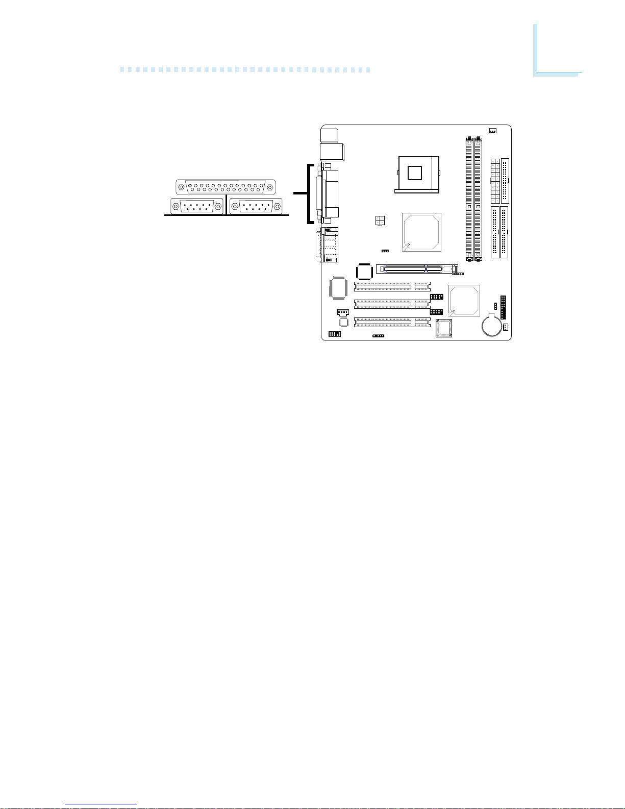
COM 1
COM 2
2.5.4 Serial Ports
The system board is equipped with onboard serial ports (COM
1: CN6 and COM 2: CN5) - both in Teal/Turquoise color.
These ports are RS-232C asynchronous communication ports
with 16C550A-compatible UARTs that can be used with modems,
serial printers, remote display terminals, and other serial devices.
BIOS Setting
Select the serial ports’ I/O address in the Integrated Peripherals
submenu of the BIOS. Refer to chapter 3 for more information.
"
30
2
Hardware Installation
Parallel
2.5.5 Parallel Port
The system board has a standard parallel port (Burgundy) at location CN8 of the system board for interfacing your PC to a
parallel printer. It suppor ts SPP, ECP and EPP modes.
BIOS Setting
Select the parallel port’s mode in the Integrated Peripherals
submenu of the BIOS. Refer to chapter 3 for more information.
Setting
SPP
(Standard Parallel Por t)
ECP
(Extended Capabilities Por t)
EPP
(Enhanced Parallel Port)
Function
Allows normal speed operation
but in one direction only.
Allows parallel port to operate in
bidirectional mode and at a speed
faster than the SPP’s data transfer
rate.
Allows bidirectional parallel por t
operation at maximum speed.
"
 Loading...