

Page 1

661GX-MLV
System Board User’s Manual
Carte Mère Manuel Pour Utilisateur
System-Platine Benutzerhandbuch
Manual del Usuario de Placas Base
Руководство Пользователя
935-661FX3-000
85700511
Page 2

2
Quick Setup Guide
1
Quick Setup
Guide
Copyright
This publication contains information that is protected by copyright. No part of it
may be reproduced in any form or by any means or used to make any
transformation/adaptation without the prior written permission from the copyright
holders. This publication is provided for informational purposes only. The
manufacturer makes no representations or warranties with respect to the
contents or use of this manual and specifically disclaims any express or implied
warranties of merchantability or fitness for any particular purpose. The user will
assume the entire risk of the use or the results of the use of this document.
Further, the manufacturer reserves the right to revise this publication and make
changes to its contents at any time, without obligation to notify any person or
entity of such revisions or changes. © 2004. All Rights Reserved.
Trademarks
Product names or trademarks appearing in this manual are for identification
purpose only and are the properties of the respective owners.
Caution
To avoid damage to the system, use the correct AC input voltage range
..
..
.
To reduce the risk of electric shock, unplug the power cord before removing the
system chassis cover for installation or servicing. After installation or servicing,
cover the system chassis before plugging the power cord.
Battery: 1. Danger of explosion if battery incorrectly replaced. 2. Replace only
with the same or equivalent type recommend
by the manufacturer. 3. Dispose of
used batteries according to the battery manufacturer’s
instructions.
Notice
The system board and accessories in the package may not come similar to the
information stated in this manual. This may differ in accordance to the sales region
or models in which it was sold. For more information about the standard
package in your region, please contact your dealer or sales representative.
FCC and DOC Statement on Class B
This equipment has been tested and found to comply with the limits for a Class
B digital device, pursuant to Part 15 of the FCC rules. These limits are designed
to provide reasonable protection against harmful interference when the
equipment is operated in a residential installation. This equipment generates, uses
and can radiate radio frequency energy and, if not installed and used in accordance with the instruction manual, may cause harmful interference to radio
communications. However, there is no guarantee that interference will not occur
in a particular installation. If this equipment does cause harmful interference to
radio or television reception, which can be determined by turning the equipment
off and on, the user is encouraged to try to correct the interference by one or
more of the following measures:
• Reorient or relocate the receiving antenna.
• Increase the separation between the equipment and the receiver.
• Connect the equipment into an outlet on a circuit different from that to
which the receiver is connected.
• Consult the dealer or an experienced radio TV technician for help.
Notice:
1. The changes or modifications not expressly approved by the party
responsible for compliance could void the user's authority to operate the
equipment.
2. Shielded interface cables must be used in order to comply with the emission
limits.
Page 3

3
1
Quick Setup Guide
Quick Setup
Guide
Table of Contents
Chapter 1
Quick Setup Guide.............................................
Chapter 2
English......................................................................
Chapter 3
Français....................................................................
Chapter 4
Deutsch...............................................................................
Chapter 5
Español............................................................................
Chapter 6
Русский......................................................................
4
11
15
19
23
27
Page 4
4
Quick Setup Guide
1
Quick Setup
Guide
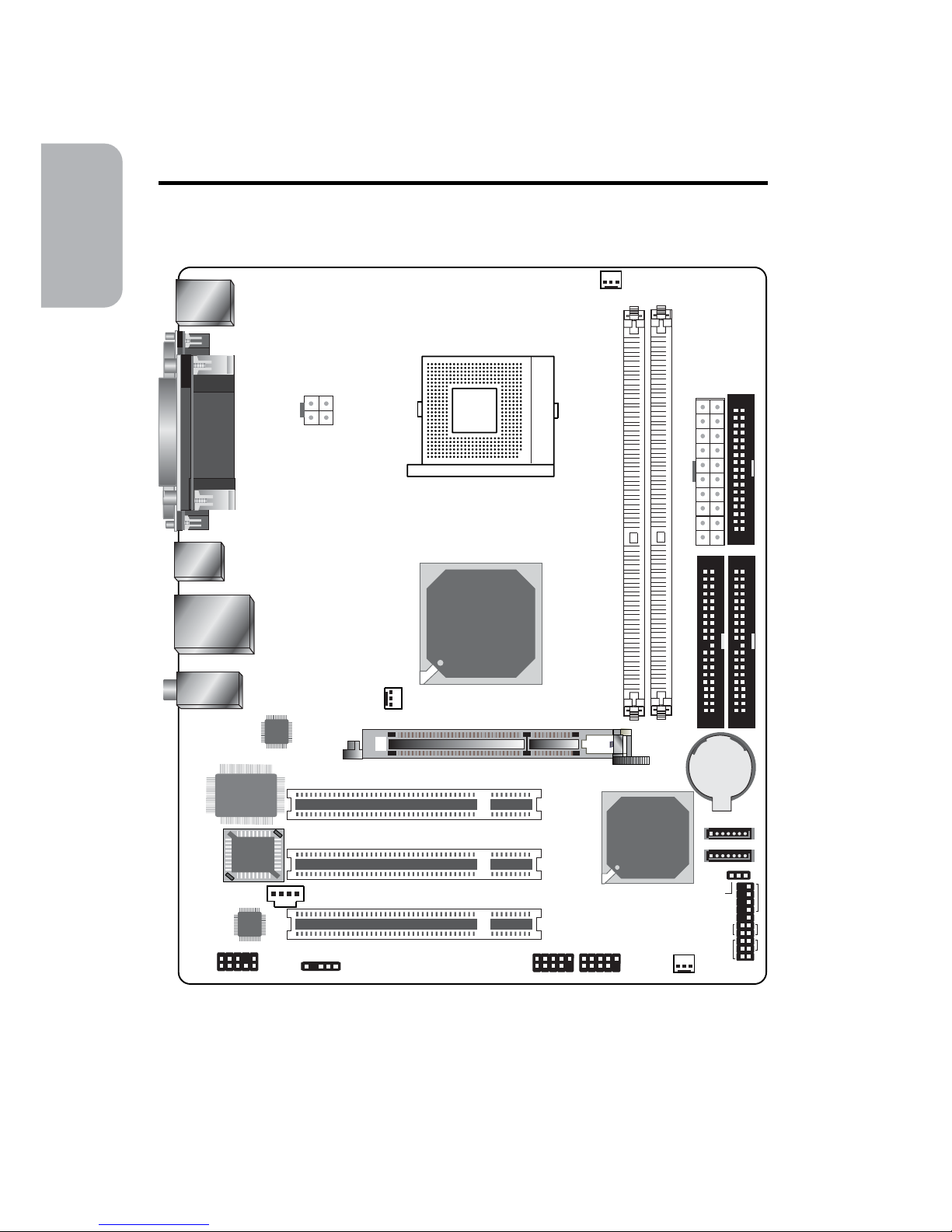
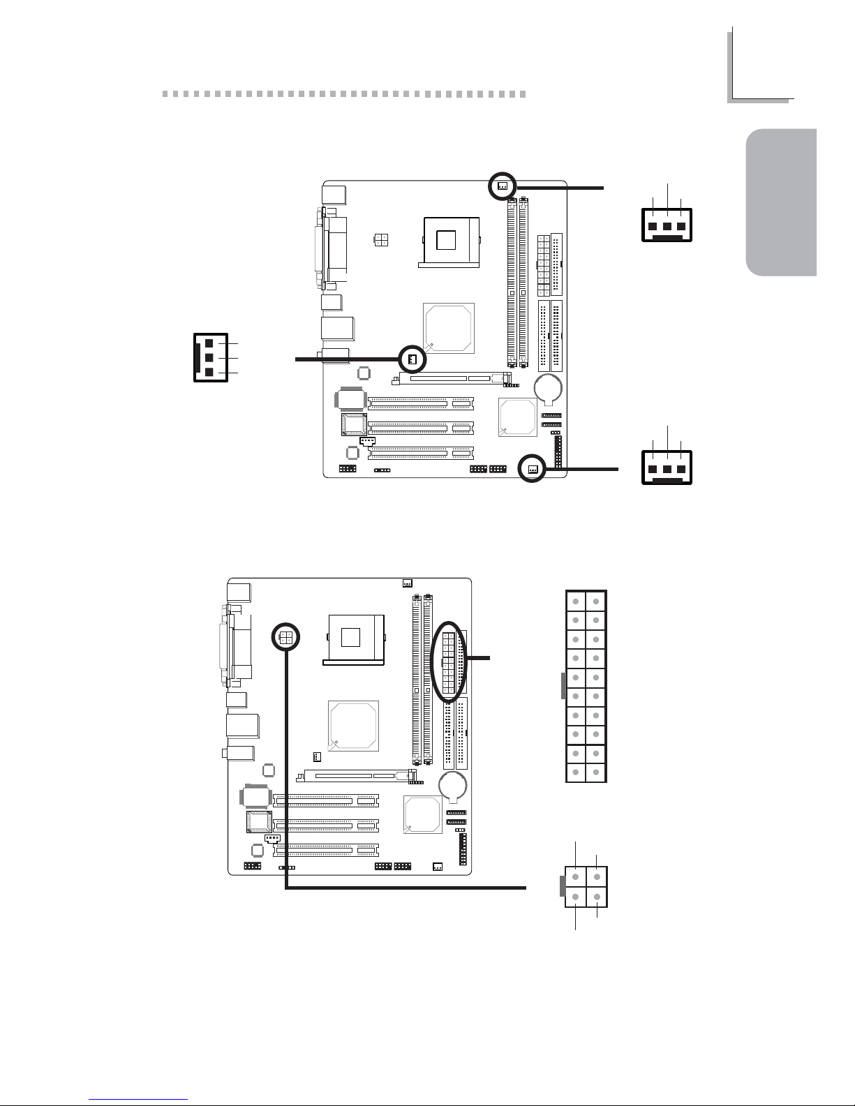
1.1 System Board Layout
Chapter 1 - Quick Setup Guide
KB/Mouse
Parallel
COM
VGA
1
+12V power
Socket 478
USB 1-2
LAN
USB 3-4
Line-out
Line-in
Mic-in
LAN
Phy
I/O
chip
BIOS
1
CD-in
Audio
Codec
1
Front audio
1
S/PDIF
SiS
661GX
SiS
964
1
CPU fan
DDR 2
DDR 1
1
AT X
power
1
FDD
1
Primary IDE
SecondaryIDE
Battery
1
1
SATA 2
S ATA 1
1
Clear CMOS (JP1)
1
NB fan
AGP
1 1
USB 5-6 USB 7-8
1
System fan
1
HD-LED
RESET
SPEAKER
PWR-LED
ATX-SW
PCI 1
PCI 2
PCI 3
Page 5
5
1
Quick Setup Guide
Quick Setup
Guide
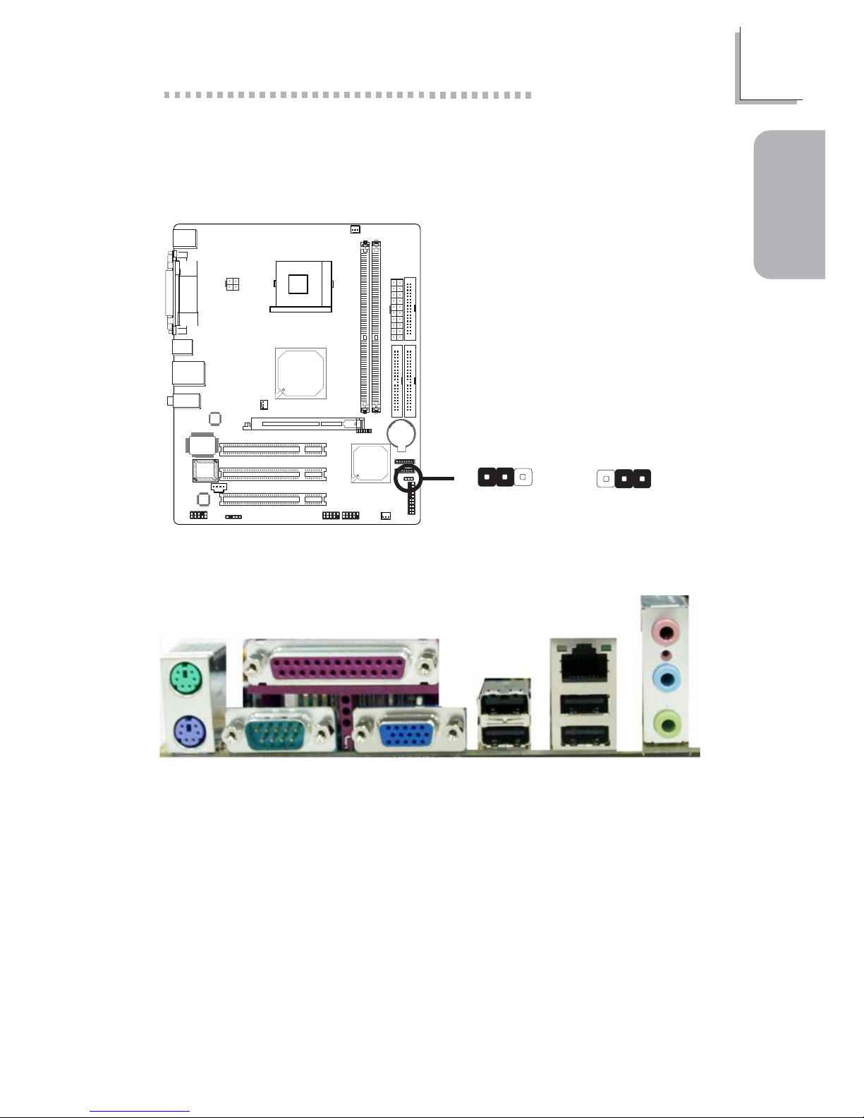
1.2 Jumper
1.2.1 Clear CMOS Data
1.3 Rear Panel I/O Ports
2-3 On:
Clear CMOS Data
1-2 On: Normal
(default)
X
JP1
312
312
PS/2
K/B
PS/2
Mouse
Parallel
RJ45
LAN
USB 3-4COM
VGA
Line-out
Line-in
Mic-in
USB 1
USB 2
Page 6
6
Quick Setup Guide
1
Quick Setup
Guide
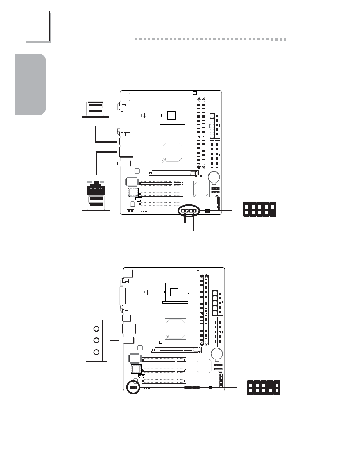
1.4 I/O Connectors
USB 4
USB 3
W
USB 5-6
W
USB 7-8
USB 2
USB 1
W
1
VCC
-Data
+Data
Ground
Key
VCC
-Data
+Data
Ground
N. C.
2
10
9
1.4.1 Universal Serial Bus Ports
1.4.2 Audio
W
Front audio
Mic
Mic Power
AuD_R_Out
N. C.
AuD_L_Out
GND
AuD_Vcc
Key
10
9
AuD_R_Return
AuD_L_Return
1
2
Line-out
Line-in
Mic-in
W
Page 7

7
1
Quick Setup Guide
Quick Setup
Guide
14
Right audio
channel
Left audio
channel
Ground Ground
1.4.3 CD-in and S/PDIF Connectors
W
W
15
VCC
Key
SPDIF out
GND
SPDIF in
CD-in
S/PDIF
1.4.4 Floppy Disk Drive Connector
34
33
21
X
Page 8
8
Quick Setup Guide
1
Quick Setup
Guide
1.4.5 SATA Connectors
17
GND
TXP
TXN
GND
RXN
RXP
GND
SATA 1
SATA 2
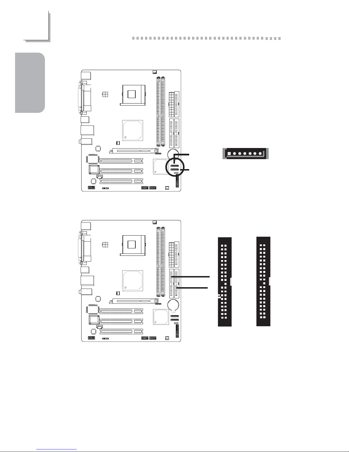
1.4.6 IDE Disk Drive Connectors
40
39
21
40
39
21
X
X
Prim. IDE
Sec. IDE
Page 9
9
1
Quick Setup Guide
Quick Setup
Guide
1.4.7 Cooling Fan Connectors
X
13
Ground
Power
N.C.
X
13
Ground
Power
N.C.
1
3
N. C.
Power
Ground
X
CPU fan
System fan
NB fan
1.4.8 Power Connectors
X
+12V
10
1
20
11
3.3V
3.3V
Ground
+5V
Ground
+5V
Ground
PW-OK
5VSB
+5V
3.3V
-12V
Ground
PS-ON
Ground
Ground
Ground
-5V
+5V
X
4
3
1
2
+12V
Ground
Ground
+12V
Page 10

10
Quick Setup Guide
1
Quick Setup
Guide
1.4.9 Front Panel Connectors
X
J13
PWR-LED
ATX-SW
HD-LED
RESET
SPEAKER
2
1
2019
Pin
3
5
14
16
8
10
18
20
7
9
13
15
17
19
2
4
6
HD-LED
(Primary/Secondary IDE LED)
Reserved
ATX-SW
(ATX power switch)
Reserved
RESET
(Reset switch)
SPEAKER
(Speaker connector)
PWR-LED
(Power/Standby LED)
Pin Assignment
HDD LED Power
HDD
N. C.
N. C.
PWRBT+
PWRBT-
N. C.
N. C.
Ground
H/W Reset
Speaker Data
N. C.
Ground
Speaker Power
LED Power (+)
LED Power (+)
LED Power (-) or Standby Signal
Page 11

11
2
English
English
2.1 Features and Specifications
Processor
• Intel® Pentium® 4 (Prescott and Northwood) processor up to
3.06GHz
- Intel Hyper-Threading Technology
- FSB: 533MHz
• Intel® Celeron® processor
- 400MHz system data bus
Chipset
• SiS® chipset
- Nor th bridge: SiS® 661GX
- South bridge: SiS® 964
System Memory
• Two 184-pin DDR DIMM sockets
• Supports 4 banks up to 2GB using PC1600 (DDR200),
PC2100 (DDR266), PC2700 (DDR333) and PC3200
(DDR400) unbuffered DDR SDRAM DIMM, 2.6V type
• 16Mb, 64Mb, 128Mb, 256Mb and 512Mb SDRAM technology
with page size from 2KB up to 16KB
BIOS
• Award BIOS, Windows® 98SE/2000/ME/XP Plug and Play
compatible
• Supports SCSI sequential boot-up
• Flash EPROM for easy BIOS upgrades
• Supports DMI 2.0 function
• 2Mbit flash memory
Energy Efficient Design
• ACPI STR (Suspend to RAM) function
• Wake-On-PS/2 Keyboard/Mouse
• Wake-On-USB Keyboard/Mouse
Chapter 2 - English
Page 12

12
English
2
English
• Wake-On-Ring (external modem)
• Wake-On-LAN
• RTC timer to power-on the system
• AC power failure recovery
Onboard Graphics Features
• Bi-directional 16-bit data bus
• Performs 1GB/s bandwidth in 133MHz x 4 mode
• 3D graphics accelerator
- Built-in high performance 256-bit 3D engine
- Suppor ts Ultra-AGPIITM up to 2.7GB/s bandwidth
- Up to 166MHz 3D engine clock speed
• 2D graphics accelerator
- Built-in hardware command queue
- Supports memory-mapped, zero wait-state, burst engine
write
- Maximum 128MB frame buffer with linear addressing
Onboard Audio Features
• AC'97 2.2 extension compliant codec
• Supports Microsoft® DirectSound/DirectSound 3D
• AC’97 supported with full duplex, independent sample rate
converter for audio recording and playback
• S/PDIF-in/out interface
• 6-channel audio output
Onboard LAN Features
• Phy fast ethernet controller
• Integrated IEEE 802.3, 10BASE-T and 100BASE-TX compatible
PHY
• 32-bit PCI master interface
• Integrated power management functions
• Full duplex suppor t at both 10 and 100 Mbps
• Supports IEEE 802.3u auto-negotiation
• Supports wire for management
Page 13

13
2
English
English
Serial ATA Interface with RAID
• Supports two SATA (Serial ATA) interfaces which are compliant with SATA 1.0 specification (1.5Gbps interface)
• Suppor ts RAID 0, RAID 1 and JBOD
PCI Bus Master IDE Controller
• Suppor ts ATA/33, ATA/66, ATA/100 and ATA/133 hard dr ives
• UDMA Modes 3, 4, 5 and 6 Enhanced IDE (data transfer rate
up to 133MB/sec.)
• Bus mastering reduces CPU utilization during disk transfer
• Suppor ts ATAPI CD-ROM, LS-120 and ZIP
Processor Socket
• Socket 478
AGP (Accelerated Graphics Port)
• Supports AGP 8x up to 2132MB/sec. and AGP 4x up to
1066MB/sec. bandwidth for 3D graphics applications
Rear Panel I/O Ports (PC 99 color-coded connectors)
• 4 USB 2.0/1.1 por ts
• 1 RJ45 LAN por t
• 1 DB-9 serial por t
• 1 DB-15 VGA por t
• 1 DB-25 parallel por t
• 1 mini-DIN-6 PS/2 mouse port
• 1 mini-DIN-6 PS/2 keyboard port
• 3 audio jacks: line-out, line-in and mic-in
I/O Connectors
• 2 connectors for 4 additional external USB 2.0/1.1 por ts
• 1 front audio connector for external line-out and mic-in jacks
• 1 CD-in internal audio connector
• 1 S/PDIF-in/out connector
• 2 Serial ATA connectors
• 2 IDE connectors
• 1 floppy drive connector
Page 14

14
English
2
English
• 2 ATX power supply connectors
• CPU fan and chassis fan connectors
Expansion Slots
• 1 AGP slot
• 3 PCI slots
PCB
• 4 layers, microATX form factor
• 24.4cm (9.6") x 20cm (7.87")
2.2 Package Checklist
The system board package contains the following items:
! The system board
! A user’s manual
! One Serial ATA cable
! One IDE cable for ATA/33/66/100/133 IDE drives
! One 34-pin floppy disk drive cable
! One SATA RAID floppy diskette
! One “Mainboard Utility” CD
If any of these items are missing or damaged, please contact your
dealer or sales representative for assistance.
Page 15

15
3
Français
Français
3.1 Caractéristiques et Spécifications
Processeur
• Les processeurs Intel® Pentium® 4 (Prescott et Northwood)
suppor te jusqu’à 3.06GHz
- Intel T echnologie Hyper-Threading
- FSB: 533MHz
• Processeur Intel® Celeron
®
- 400MHz vitesse du bus
Chipset
• SiS® chipset
- Pont Nord: SiS® 661GX
- Pont Sud: SiS® 964
Mémoire Système
• 2 sockets DDR DIMM 184 broches
• Supporte 4 bancs de mémoire jusqu’à 2GB en utilisant les
modules PC1600 (DDR200), PC2100 (DDR266), PC2700
(DDR333) et PC3200 (DDR400) non-tamponnés. DDR
SDRAM DIMM, type 2.6V
• Technologie SDRAM 16Mb, 64Mb, 128Mb, 256Mb et 512Mb
avec la page de 2KB à 16KB
BIOS
• Compatible avec Award BIOS, Windows® 98SE/2000/ME/XP
Plug and Play
• Supporte l’amorçage séquentiel SCSI
• EPROM Flash pour une mise à niveau facile du BIOS
• Supporte la fonction DMI 2.0
• Mémoire Flash 2Mbit
Design à Haut Rendement Énergétique
• ACPI STR (Suspend to RAM) fonction
• Réveil-Sur-PS/2 Clavier/Souris
Chapter 3 - Français
Page 16

16
Français
3
Français
Français
• Eveil Clavier/Souris USB
• Eveil Sonnerie
• Réveil Par Le Réseau
• Minuterie RTC pour allumer le système
• Récupération après Défaillance d’Alimentation CA
Fonctions Graphiques Intégrées
• Bus de données de 16 bits bi-directionnel
• Bande passante de 1GB/s dans le mode de 133MHz x 4
• Accélérateur graphique 3D
- Moteur 3D 256 bits de haute perfromance intégré
- Soutien de l’Ultra-AGPIITM jusqu’à 2.7GB/s de bande
passante
- Jusqu’à 166MHZ de vitesse d’horloge du moteur 3D
• Accélérateur graphique 2D
- Queue de commandes intégrée
- Soutien de la mémoire mappée, du moteur d’écriture
rafale sans état d’attente
- Tampon de trame maximal de 128MB à l’adressage linéaire
Caractéristiques Audio sur Carte
• Codec conforme à l’extension AC’97 2.2
• Supporte DirectSound de Microsoft® / DirectSound 3D de
Microsoft
®
• AC’97 supporté avec full duplex, convertisseur de vitesse
d’échantillonnage indépendant pour enregistrement audio et
lecture.
• Interface entrée/sortie S/PDIF
• Sortie audio 6-canaux
Fonctionnalités Onboard LAN
• Utilise le contrôleur Phy
• IEEE 802.3, 10BASE-T et 100BASE-TX intégrés compatibles
PHY
• Interface maître PCI 32 bits
• Fonctions de gestion d’alimentation intégrées
• Suppor t Full duplex à 10 et 100 Mbps
• Supporte l’auto négociation IEEE 802.3u
• Support câble pour la gestion
Page 17

17
3
Français
Français
Interface Serial ATA RAID
• Supportant 2 interface SATA (Serial ATA) compatible avec la
spécification SATA 1.0 (bande passante à 1.5Gbps)
• Suppor te RAID 0, RAID 1 and JBOD
Contrôleur IDE de BUS Maître PCI
• Supporte des disques durs ATA/33, ATA/66, ATA/100 et
ATA/133
• IDE Améliorés Mode 3, 4, 5 et 6 UDMA (vitesse de transfert
de données allant jusqu’à 133Mo/sec.)
• La gestion de Bus réduit l’utilisation du CPU pendant les
transferts sur disque
• Suppor te les CD-ROM ATAPI, LS-120 et ZIP
Socket Processeur
• Socket 478
AGP (Accelerated Graphics Port)
• Supporte 8x AGP avec une bande passante allant jusqu’à
2132Mo/sec et 4x AGP avec une bande passante allant jusqu’à
1066Mo/sec pour les applications graphiques 3D
Le Panneau des Ports Entrée/Sortie en Arrière
(Connecteurs PC 99 avec codes couleur)
• 4 por ts USB 2.0/1.1
• 1 por t RJ45 LAN
• 1 por t série DB-9
• 1 por t VGA DB-15
• 1 por t parallèle DB-25
• 1 port souris PS/2 mini-DIN-6
• 1 port clavier PS/2 mini-DIN-6
• 3 prises audio: ligne de sortie (line-out), ligne d’entrée (linein) et entrée micro (mic-in)
Page 18

18
Français
3
Français
Français
Connecteurs Entrée/Sortie
• 2 connecteurs pour 4 por ts USB 2.0/1.1 supplémentaires
• 1 connecteur audio de l’avant pour la sortie ligne et l’entrée
micro
• 1 connecteur CD-in audio internes
• 1 connecteur entrée/sortie S/PDIF
• 2 connecteur s Serial ATA
• 2 connecteurs IDE
• 1 connecteur de lecteur de disquettes
• 2 connecteurs d’alimentation ATX
• Connecteurs de ventilateurs de CPU et de châssis
Logements d’Extension
• 1 slot AGP
• 3 slots PCI
PCB
• 4 couches, facteur de forme microATX
• 24.4cm (9.6") x 20cm (7.87")
3.2 Liste de Vérification de l’Emballage
L’emballage de la car te système contient les éléments suivants:
! 1 carte système
! 1 manuel utilisateur
! 1 câble série ATA
! 1 câble IDE pour les lecteurs IDE ATA/33/66/100/133
! 1 câble 34 broches pour lecteur de disquette
! 1 disquette SATA RAID
! 1 CD “Mainboard Utility”
Si l’un de ces éléments n’était pas dans l’emballage ou s’il était
endommagé, veuillez contacter votre revendeur ou votre
représentant.
Page 19

19
4
Deutsch
Deutsch
4.1 Leistungsmerkmale und Technische Daten
Prozessor
• Intel® Pentium® 4 (Prescott und Nor thwood) Prozessor von bis
zu 3.06GHz
- Intel Hyper-Threading Technologie
- FSB: 533MHz
• Intel® Celeron® Prozessor
- 400MHz Systemdatenbus
Chipsatz
• SiS® chipset
- Nordbrücke: SiS® 661GX
- Südbrücke: SiS® 964
Systemspeicher
• 2 184-Stift DDR DIMM Buchsen
• Hält 4 Datenbanken des Speichers bis 2GB durch die
Moduln: PC1600 (DDR200), PC2100 (DDR266), PC2700
(DDR333) und PC3200 (DDR400) ohne Dämpfer DDR
SDRAM DIMM, 2.6V-Typ
• 16Mb, 64Mb, 128Mb, 256Mb und 512Mb Technoloqie-SDRAM
mit der Seite bis 2KB zu 16KB
BIOS
• Kompatibilität mit Award BIOS, Windows® 98SE/2000/ME/XP
Plug and Play
• Unterstützung des sequentiellen SCSI-Ladens
• Flash EPROM für ein einfaches Aktualisieren des BIOS
• Unterstützung der DMI-2.0-Funktion
• Flash-Speicher (2Mbit)
Energomisches Design
• ACPI STR (Suspend to RAM) funktion
• Wecken bei Betätigung der PS/2 Tastatur/Maus
Chapter 4 - Deutsch
Page 20

20
Français
4
Deutsch
Deutsch
• Wecken bei USB-Tastatur/Maus
• Wecken bei Klingeln
• Wecken des Systems durch das Netzwerk
• RTC-Taktgeber zum Einschalten des Systems
• Wiederherstellung der Wechselstromversorgung nach einem
Ausfall
Die Einbaufunktionen die Schaubilder
• Bi-richtender 16-bit Reifen
• Die Durchlaßfähigkeit ist 1GB/s im Regime 133MHz x 4
• Die graphische 3D-Beschnigung
- Ein hochleistungsfähiger 256-bit 3D-Einbauschieber
- Halt Ultra-AGPIITM mit der Durchlaßfähigkeit bis 2.7GB/s
- Die Taktfrequenz des 3D-Schebers ist 166MHz
• Die graphische 2D-Beschnigung
- Der einbauen Gerätebefehl
- Hält der Mapped-Speicher, der Nullstillstand, der Schieber
der Spitzenaufnahme
- Der Maximaldämpfer des 128MB-Gstelles mit der
Linienadressierung
Audiomerkmale auf Platine
• Codec für AC’97 2.2-Erweiterung
• Unterstützung der Microsoft DirectSound/DirectSound 3D
• AC’97 Unterstützung des Audiotreiber und Audiowiedergabe
• S/PDIF-In/Aus-Schnittstelle
• 6-Kanal-Audioausgang
Merkmale des LANs auf Platine
• Benutzung des Phy für die Fast-Ethernet-Verbindung
• Integrierter IEEE 802.3, 10BASE-T und 100BASE-TX
kompatibler PHY
• 32-Bit-PCI-Master-Schnittstelle
• Integrierte Power-Management-Funktionen
• Vollduplex-Unterstützung bei 10 und 100 Mbps
• Unterstützung der IEEE-802.3u-Auto-Negotiation
• Unterstützung des Leiters für das Management
Page 21

21
4
Deutsch
Deutsch
Serial ATA RAID Schnittstelle
• Unterstützt 2 SATA (Serielle ATA)-Schnittstelle, die mit SATA
1.0 Spezifikation (1.5Gigabits Schnittstelle) konform is
• RAID 0, RAID 1 und JBOD
PCI-Bus-Master-IDE-Controller
• Unterstützung der Festplatten ATA/33, ATA/66, ATA/100 und
ATA/133
• Erweitertes IDE des UDMA-Modus 3, 4, 5 und 6 (Datenübertragungsgeschwindigkeit von bis zu 133MB/Sek.).
• Verminderte CPU-Benutzung während Diskettenübertragung
dank dem Bus-Master
• Unterstützung des ATAPI CD-ROMs, LS-120 und ZIP
Prozessor Socket
• Buchse 478
AGP (Accelerated Graphics Port)
• Für die 3D-Grafikanwendungen unterstützt die universelle
AGP-Steckfassung einen AGP 8x mit einer Bandweite von bis
zu 2132MB/Sek. sowie einen AGP 4x mit einer Bandweite von
bis zu 1066MB/Sek.
Ein-/Ausgabe-Porte an der Rückwand
(PC 99 mit farbkodierten Steckverbindungen)
• 4 USB 2.0/1.1-Anschlüsse
• 1 RJ45 LAN-Anschlüsse
• 1 serieller DB-9-Anschluß
• 1 VGA DB-15-Anschluß
• 1 DB-25-Parallelanschluß
• 1 Mini-DIN-6-Anschluß für eine PS/2-Maus
• 1 Mini-DIN-6-Anschluß für eine PS/2-Tastatur
• 3 Audio-Anschlußbuchsen: Ausgangsleitung, Eingangsleitung und
Mikrofon-Eingang
Page 22

22
Français
4
Deutsch
Deutsch
Ein-/Ausgabe-Steckverbinder
•2 Anschlußfassung für 4 zusätzliche externe USB 2.0/1.1-
Anschlüsse
• 1 Frontaudioanschluß für die externe Ausgangsleitung und den
Mikrofoneingang
• 1 CD-in interne Audioanschluß
• 1 S/PDIF-in/Aus-Steckverbinder
• 2 Serial ATA-Anschlüsse
• 2 IDE-Anschlüsse
• 1 Floppy-Anschlüsse
• 2 Anschlußstecker für das ATX-Netzgerät
• CPU- und Chassis-ventilator-Anschlüsse
Erweiterungssteckfasssungen
• 1 AGP-Einbauplätzen
• 3 PCI-Einbauplätzen
Die Druckplatte
• 4 Variationen, der Formfaktor microATX
• 24.4cm (9.6") x 20cm (7.87")
4.2 Verpackungsliste
In der Verpackung der Systemplatine sind folgende Artikel
enthalten:
! 1 Systemplatine
! 1 Benutzerhandbuch
! 1 Serial ATA-Kabel
! 1 IDE-Kabel
! 1 Floppy-Kabel
! 1 Diskette SATA RAID
! 1 CD mit “Mainboard Utility”
Fehlt einer dieser Artikel oder weist einer dieser Artikel
Beschädigungen auf, wenden Sie sich an Ihren Händler oder
Ve rtreter.
Page 23

23
5
Español
Español
5.1 Características y Especificaciones
Procesador
• Procesador Intel® Pentium® 4 (Prescott y Nor thwood) máximo
de 3.06GHz
- Intel Tecnología Hyper-Threading
- FSB: 533MHz
• Procesador Intel® Celeron
®
- 400MHz canal de datos del sistema
Chipset
• SiS® chipset
- Puente Nor te: SiS® 661GX
- Puente Sur: SiS® 964
Memoria de Sistema
• 2 enchufes de 184-terminales DDR SDRAM DIMM
• Soporta 4 bancos de memoria hasta 2GB usando los
módulos PC1600 (DDR200), PC2100 (DDR266), PC2700
(DDR333) y PC3200 (DDR400) no de tope DDR SDRAM
DIMM, de 2.6V tipo
• 16Mb, 64Mb, 128Mb, 256Mb y 512Mb SDRAM tecnología con
página de 2KB hasta 16KB
BIOS
• Award BIOS, Windows® 98SE/2000/ME/XP Enchufar y Usar
compatible
• Soporta el incio de secuencia de SCSI
• Parpadea EPROM para fácil actualización de BIOS
• Soporta la función de DMI 2.0
• Memoria Instante (2Mbitios)
Diseño Energia Eficiente
• ACPI STR (Suspend to RAM) función
• PS/2 Teclado/Ratón de Wake-On
Chapter 5 - Español
Page 24

24
5
Español
Español
• Teclado/Ratón de Wake-On-USB
• Wake-On-Ring (external modem)
• Wake-On-LAN
• Temporizador de RTC para encender el sistema
• Recuperación de Fracaso de Energía AC
Funciones Incorporadas de Gráfica
• La barra bi-direccionada de 16 bit
• Capacidad de información 1GB/s en formato de 133MHz x 4
• Acelerador gráfico 3D
- El motor 3D incorporado de gran efectividad de 256 bit
- Soporta Ultra-AGPIITM con capacidad de información hasta
2.7GB/s
- La frecuencia de compás del motor 3D de 166MHz
• Acelerador gráfico 2D
- Mando incorporado de hardware
- Soporta memoria-mapped, estadía de cero, motor de
grabación embarazoso
- Buffer de al máximo 128MB frames con la dirección lineal
Características de Audio En Tablero
• AC’97 2.2 extensión complaciente codec
• Soporta DirectSound de Microsoft® / DirectSound 3D de
Microsoft
®
• AC’97 soporta full duplex, independiente frecuencia de
muestreo convertido por audio recording and playback
• Interfáz de S/PDIF-in/out
• Output auricular de 6-canal
Características de LAN Interno
• Utiliza el rápido controlador Ethernet de Phy
• IEEE 802.3, 10BASE-T y 100BASE-TX integrado de PHY compatible
• Interfaz maestro de 32-bit PCI
• Funciones de administración de energía integrado
• Soporte dúplex completo en ambos 10 y 100 Mbps
• Soporta auto negociación de IEEE 802.3u
• Soporta alambre para la administración
Page 25

25
5
Español
Español
Interfaz Serial ATA RAID
• Permite 2 interfaz SATA (Serie ATA) la cual es compatible
con la especificación SATA 1.0 (interfaz 1.5Gbps)
• RAID 0, RAID 1 y JBOD
Controlador de IDE Maestro de Bus PCI
• Soporta discos duros ATA/33, ATA/66, ATA/100 y ATA/133
• UDMA modo 3, 4, 5 y 6 ensanchado IDE (la transfererncia
de datos es 133MB/sec.)
• Bus mastering reduce la carga a la Unidad Central de
Proceso
• Sopor ta ATAPI CD-ROM, LS-120 y ZIP
Procesador Zócalo
• Zócalo 478
AGP (Accelerated Graphics Port)
• Soporta AGP 8x con 2132MB/sec. y AGP 4x con 1066MB/sec.
para las tearjetas 3D
Panel de Reverso de Conectores de Entrada - Salida
(Conectores de PC 99 color-cifrado)
• 4 puer tos de USB 2.0/1.1
• 1 puer to de RJ45 LAN
• 1 puer to de serie DB-9
• 1 puer to de VGA DB-15
• 1 puer to paralelo de DB-25
• 1 puerto de ratón PS/2 mini-DIN-6
• 1 puerto de teclado mini-DIN-6 PS/2
• 3 enchufes de audio: línea de salida, línea de entrada y mic de
entrada
I/O Conectores
• 2 conectores para 4 puer tos de USB 2.0/1.1 externo adicional
• 1 conectador audio delantero para la salida extrema de linea
y el micro
• 1 conector de CD-in audio interno
• 1 conector de S/PDIF-in/out
Page 26

26
5
Español
Español
• 2 conectores de Serial ATA
• 2 conectores de IDE
• 1 conector de disquete
• 2 conectores de fuente de alimentación de ATX
• 2 conectores de abanicos de CPU y chasis
Ranuras de Expansión
• 1 slot AGP
• 3 slots PCI
La Placa Imprenta
• 4 variaciones, form-factor microATX
• 24.4cm (9.6") x 20cm (7.87")
5.2 Lista de Chequeo del Paquete
El paquete del tablero de sistema contiene los siguientes
artículos:
! 1 tablero de sistema
! 1 manual de usuario
! 1 cable serial ATA
! 1 cable de IDE para las unidades de ATA/33/66/100/133 IDE
! 1 cable de unidad de disquete de 34-terminales
! 1 disquette flojo SATA RAID
! 1 CD de “Mainboard Utility”
Si cualquieres de estos artículos están perdidos o dañados, favor
de ponerse en contacto con su tratante o representantes de
venta para la asistencia.
Page 27

27
6
РусскийРусский
РусскийРусский
Русский
РусскийРусский
РусскийРусский
Русский
6.1 Характеристики и свойства6.1 Характеристики и свойства
6.1 Характеристики и свойства6.1 Характеристики и свойства
6.1 Характеристики и свойства
ПроцессорПроцессор
ПроцессорПроцессор
Процессор
• Процессор Intel® Pentium® 4 (Prescott и Northwood) до
3.06GHz
- Intel технологией Hyper-Threading
- FSB: 533MHz
• Процессор Intel® Celeron
®
- 400MHz системная шина
ЧипсетЧипсет
ЧипсетЧипсет
Чипсет
• SiS® chipset
- Северный Мост: SiS® 661GX
- Южный Мост: SiS® 964
ПамятьПамять
ПамятьПамять
Память
• 2 DIMM гнезда под 184-pin DDR SDRAM
• Поддерживает 4 банков памяти до 2GB модулями
PC1600 (DDR200), PC2100 (DDR266), PC2700
(DDR333) или PC3200 (DDR400) небуф. DDR SDRAM
DIMM, 2.6V типа
• 16Mb, 64Mb, 128Mb, 256Mb и 512Mb SDRAM
технология со страницей от 2KB до 16KB
BIOSBIOS
BIOSBIOS
BIOS
• Award BIOS, Windows
®®
®®
®
98SE/2000/ME/XP Plug and
Play
• Поддерживает загрузку SCSI
• Flash EPROM для обновления BIOS
• Поддерживает функцию DMI 2.0
• 2Mbit Flash Память
Энергомичный ДизайнЭнергомичный Дизайн
Энергомичный ДизайнЭнергомичный Дизайн
Энергомичный Дизайн
• ACPI STR (Suspend to RAM)
• Активизация На Движение Мыши
Глава Глава
Глава Глава
Глава
6 6
6 6
6
- -
- -
-
Русский языкРусский язык
Русский языкРусский язык
Русский язык
Page 28

28
РусскийРусский
РусскийРусский
Русский
6
РусскийРусский
РусскийРусский
Русский
• Активизация На Нажатие Кнопки USB Клавиатуры
• Активизация На Входящий Звонок
• Активизация На Сетевое Событие
• RTC Таймер для Включения Системы
• Скачки Напряжения
Встроенные Функции ГрафикиВстроенные Функции Графики
Встроенные Функции ГрафикиВстроенные Функции Графики
Встроенные Функции Графики
• Би-направленная 16-битная шина
• Пропускная способность 1GB/s в режиме 133MHz x
4
• 3D графический ускоритель
- Встроенный высокопроизводительный 256-
битный 3D движок
- Поддерживает Ultra-AGPIITM с пропускной
способностью до 2.7GB/s
- Тактовая частота 3D движка 166MHz
• 2D графический ускоритель
- Встроенная аппаратная команда
- Поддерживает маппированную память, нулевой
простой, движок пиковой записи
- Максимальный буфер фреймов 128MB с
линейной адресацией
Встроенный ЗвукВстроенный Звук
Встроенный ЗвукВстроенный Звук
Встроенный Звук
• Расширенный кодек AC’97 2.2 S/PDIF
• Поддерживает Microsoft
®®
®®
®
DirectSound / DirectSound 3D
• AC’97 поддерживается с полнодуплексным,
независимым конвертором частоты для записи и
проигрывания звука
• S/PDIF-in/out
• 6-и канальный звуковой выход
Встроенные сетевые функцииВстроенные сетевые функции
Встроенные сетевые функцииВстроенные сетевые функции
Встроенные сетевые функции
• Быстрый Ethernet контроллер Phy
• Встроенный интерфейс IEEE 802.3, 10BASE-T и
100BASE-TX совместимый PHY
• интерфейс мастер 32-bit PCI
• Встроенные функции управления питанием
• Полнодуплексная поддержка на 10 и 100 Mbps
Page 29

29
6
РусскийРусский
РусскийРусский
Русский
РусскийРусский
РусскийРусский
Русский
• Поддерживает IEEE 802.3u auto-negotiation
• Работа через шнур управления
Интерфейс Serial AИнтерфейс Serial A
Интерфейс Serial AИнтерфейс Serial A
Интерфейс Serial A
TT
TT
T
A RAIDA RAID
A RAIDA RAID
A RAID
• Поддерживает один интерфейс SATA (Serial ATA),
совместимый со спецификацией SATA 1.0
• RAID 0, RAID 1 è JBOD
Контроллер PCI IDE Мастер ШиныКонтроллер PCI IDE Мастер Шины
Контроллер PCI IDE Мастер ШиныКонтроллер PCI IDE Мастер Шины
Контроллер PCI IDE Мастер Шины
• Поддерживает жесткие диски ATA/33, ATA/66, ATA/
100 и ATA/133
• UDMA Mode 3, 4, 5 и 6 Расширенный IDE (скорость
передачи данных до 133МБ/сек.)
• Мастеринг шины снижает нагрузку на центральный
процессор
• Поддерживает ATAPI CD-ROM, LS-120 и ZIP
ЧипсетЧипсет
ЧипсетЧипсет
Чипсет
Socket Socket
Socket Socket
Socket
• Socket 478
AGP (Accelerated Graphics Port)AGP (Accelerated Graphics Port)
AGP (Accelerated Graphics Port)AGP (Accelerated Graphics Port)
AGP (Accelerated Graphics Port)
• AGP 8x (2132MB/ñåê) è AGP 4x (1066MB/ñåê)
Порты Ввода/Вывода (I/O) задней панелиПорты Ввода/Вывода (I/O) задней панели
Порты Ввода/Вывода (I/O) задней панелиПорты Ввода/Вывода (I/O) задней панели
Порты Ввода/Вывода (I/O) задней панели
• 4 USB 2.0/1.1 порта
• 1 RJ45 LAN ïîðò
• 1 DB-9 порта
• 1 DB-15 VGA порта
• 1 DB-25 параллельный порт
• 1 ìèíè-DIN-6 PS/2 ïîðò äëÿ ìûøè
• 1 мини-DIN-6 PS/2 порт для клавиатуры
• 3 гнезда для звука: выход, вход и микрофон
Разъемы Ввода/ВыводаРазъемы Ввода/Вывода
Разъемы Ввода/ВыводаРазъемы Ввода/Вывода
Разъемы Ввода/Вывода
• 2 разъем для 4-х дополнительных внешних USB 2.0/
1.1 портов
• 1 разъем для внешнего линейного выхода и
микрофона
Page 30

30
РусскийРусский
РусскийРусский
Русский
6
РусскийРусский
РусскийРусский
Русский
• 1 разъем CD-in
• 1 разъем S/PDIF-in/out
• 2 Serial ATA разъема
• 2 IDE разъема
• 1 floppy разъем
• 2 разъема питания ATX
• Вентилятор процессора и вентилятор корпуса
СлотыСлоты
СлотыСлоты
Слоты
• 1 AGP слотов
• 3 PCI слотов
Печатная платаПечатная плата
Печатная платаПечатная плата
Печатная плата
• 4 вариаций, форм-фактор microATX
• 24.4ñì (9.6") x 20ñì (7.87")
6.2 Комплектация6.2 Комплектация
6.2 Комплектация6.2 Комплектация
6.2 Комплектация
Комплектация поставки материнской платы:
; Материнская плата
; Руководство пользователя
; Два шлейф Serial ATA
; Один IDE шлейф для жестких
; Один 34-pin шлейф для дисковода
; Одна дискета SATA RAID
; Îäèí CD ñ “Mainboard Utility”
Если в комплекте из этого чего-то не хватает или чтото испорчено, пожалуйста, свяжитесь со своим
дилером или продавцом.
 Loading...