

D/F MAC, MAT Instruction Manual
Instruction Manual 653AM
MAC/MAT Long
Revised 06/2014
D/F MACHINE SPECIALTIES, INC.
MIG & TIG Welding Products, Consumables & Accessories
1750 Howard Drive, North Mankato, MN 56003
Phone: (507) 625-6200 Fax: (507) 625-6203
www.dfmachinespecialties.com
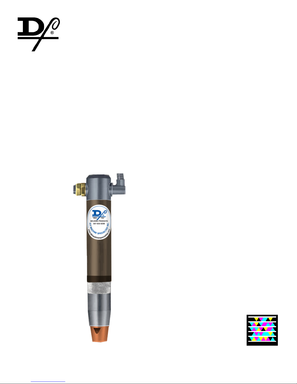
AIR COOLED MIG BARRELS
Model MAC - Collet Action (Slip-In Tip)
Model MAT - Threaded Current Tip
Shielding Gas Connection is in the Vertical
Barrel Length - 8.625”
INSTRUCTIONS, PARTS & SPECIFICATIONS MANUAL
D/F MACHINE SPECIALTIES is a world leader in the design, development, and manufacture of “MIG” (GMAW) & “TIG” (GTAW) weld-
ing products, consumables and accessories. D/F offers several types of manual Air or Water-Cooled “MIG” welding tools, and with the
increased use of automated and robotic welding systems, a demand has been created for welding tools of the highest quality, durability
and interchangeability. For over forty years, D/F welding products have been used extensively on “MIG” and “TIG” welding applications.
This experience, coupled with patented design features, unavailable on any other competitive equipment, has made D/F welding tools
the most advanced “MIG” and “TIG” welding guns and barrels for semi-automatic, automatic or robotic welding applications.
This Catalog is a guide to helping you select the proper tool for a given semi-automatic, automatic or robotic welding application. The following is only a partial listing of available semi-automatic, automatic and robotic guns. For further information on special “MIG” and “TIG”
requirements, please consult the factory.
Customer satisfaction and customer benets are the center
points of all strategic contents
The spirit of the D/F Machine Specialties personnel is to listen to
and to integrate the customer throughout the process, to develop
and design marketable products, to present prototypes, to carry
out pilot tests and to prepare for and be open to new technology
and tasks. We attract and carefully select talented individuals
who share our values. Together we will nurture and sustain a
work environment with two-way communication, training, mentoring, and rewarding career opportunities.
Innovation and quality
Innovation and quality come from being receptive and willing to
learn from others. We encourage our people to be creative and
take risks in the pursuit of excellence. Innovative practices are
deeply rooted in every one of our employees, a philosophy that
leads to continuous product development and industry rsts.
Progress
By remaining condent, focused, and persistent in challenging
times, we will discover opportunity. Commitment to quality and
the pursuit on innovation ensure that D/F Machine Specialties
will remain an industry leader for years to come.
Commitment to excellence
At D/F Machine Specialties we commit to design, build and deliver
premium products and superior customer support to quality driven
welding professionals. Customers still to this day choose D/F
over competitors because of our responsiveness and exibility.
Customers will continue to choose D/F tomorrow for our superior
hand-made products and service. To ensure this, we need creative and competent personnel in all business divisions, an intensive exchange of thoughts and ideas with all users, participation
in working and study groups within the eld of welding technology
and intensive cooperation with institutes and universities.
Teamwork
Striving for excellence is a commitment that is an integral component of the D/F Culture. Our team of skilled and dedicated
employees takes pride in the excellence products they produce.
Each of us willingly accepts personal responsibility for meeting
our commitments and we hold each other to a high standard of
accountability.
Responsibility
We will continually strive to be environmentally responsible and to
support the health and safety of our employees, customers, and
neighbors. We continue to support the communities in which we
operate and the industries in which we participate.
Thank You for Choosing D/F Machine Specialties

TABLE OF CONTENTS
Introduction, Ordering Information .................................................................................5
Required Tools List for Disassembly & Assembly .......................................................6-7
How Do I Cut, Fit, and Install a New Liner?...................................................................8
What is the Proper Use of the Nozzle Thread Chaser Tap? ..........................................9
(Table I) Gas Nozzles, (Tables II) Current Tips ............................................................10
Air-Cooled Machine Barrel Model MAC - Parts ........................................................... 11
Air-Cooled Machine Barrel Model MAT - Parts ............................................................12
(Table 3) Casings, (Table 4) Liners, (Table 5) Recommended Spare Parts ................13
Air-Cooled Machine Barrel - Remote Mounting & Utilities ...........................................14
Utility Station - Air-Cooled Barrels ...............................................................................15
Wire Feeder Adapters & Inlets.....................................................................................16
Troubleshooting ......................................................................................................17-20

SAFETY MEASURES - **PLEASE READ!**
Welding is not particularly hazardous when certain safety practices are followed. Anyone using this equipment should be thoroughly
trained in safe welding practices. Failure to observe safe practices may cause serious injury. Handling welding torches presents no danger if the appropriate safety regulations are strictly adhered to. For example:
• Starting-up procedures must be reserved for those fully conversant with processes relating to arc welding equipment.
• Arc welding can prove damaging to eyes, skin, and hearing! It is therefore imperative that the Accident Prevention Regulations UVV 26.0 and VGB 15 are
fully observed and that all protective clothing, eye and ear protectors specied are worn.
• The load data given are maximum limit gures. Overloading will inevitably damage the torch!
• Before changing wear parts, disconnect for the power supply.
• The operating instructions for the individual welding components - e.g. power source, wire feed and cooling unit must be followed.
• Never pull the cable assembly across sharp edges or set down close to weld spatter or on a hot workpiece.
• Those not involved in the welding process should be protected by curtains or partitions from radiation and the danger of being dazzled.
• When handling gas cylinders, consult the instructions issued by the manufacturers and the suppliers of the pressurized gas.
• Workpieces which have been degreased using chlorinated solvents must be sprayed down with clean water before welding starts to avoid the risk of
phosgene forming. For the same reason, no degreasing baths containing chlorine must be placed close to the welding point.
• All vapors given off by metals can cause harm and a special warning is attached to lead, cadmium, copper, zinc, and beryllium. If necessary, take appropriate precautions (by providing adequate ventilation or an extraction system) to ensure that the legal maximum levels of toxic concentrations are not
exceeded.
For more information, refer to the following standards in their latest revisions and comply as applicable.
• ANSI Standard Z49.1, SAFETY IN WELDING AND CUTTING obtainable from the American Welding Society, 2501 N.W. 7th St., Miami, FL 33125.
• ANSI Standard Z41.1, STANDARD FOR MEN’S SAFETY - TOE FOOTWEAR obtainable from the American National Standards Institute, 1430 Broadway,
New York, NY 10018.
• ANSI Standard Z49.2, FIRE PREVENTION IN THE USE OF CUTTING AND WELDING PROCESSES obtainable from the American National Standards
Institute, 1430 Broadway, New York, NY 10018.
• OSHA, SAFETY AND HEALTH STANDARDS, 29CRF 1910, obtainable from the U.S. Government Printing Ofce, Washington, D.C. 20402.
• AWS Standard A6.0, WELDING AND CUTTING CONTAINERS WHICH HAVE HELD COMBUSTABLES obtainable from the American Welding Society,
2501 N.W. 7th St., Miami, FL 33125.
• NFPA Standard 70-1978, NATIONAL ELECTRICAL CODE obtainable from the National Fire Protection Association, 470 Atlantic Avenue, Boston, MA
02210.
• ANSI Standard Z88.2, “Practice for Respiratory Protection” obtainable from the American National Standards Institute, 1430 Broadway, New York, NY
10018.
• ANSI Standard Z87.1, SAFE PRACTICES FOR OCCUPATION AND EDUCATIONAL EYE AND FACE PROTECTION obtainable from the American
National Standards Institute, 1430 Broadway, New York, NY, 10018.
• NIOSH, SAFETY AND HEALTH IN ARC WELDING AND GAS WELDING AND CUTTING obtainable from the Superintendent of Documents, U.S. Printing
Ofce, Washington, D.C. 20402.
• American Welding Society Standard AWSF4.1 “Recommended Safe Practices for the Preparation for Welding and Cutting of Containers and Piping That
Have Held Hazardous Substances”, obtainable from the American Welding Society, 2501 N.W. 7th St., Miami, FL 33125.

INTRODUCTION
This manual covers the models MAC/MAT Air Cooled Machine Barrels for mechanized MIG welding with a barrel length
of 8.625” and a shielding gas connection in the vertical. Direct mounting is accomplished by utilizing interconnections to
the welding head or wire drive. Remote mounting is accomplished by an insulated mounting bracket and utilizing a casing/
conduit and an adapter to the wire drive.
Two models are available. The model MAC features a slip-in current tip fastened by a collet nut. The wire diameter range
includes .030”-1/16” with a current capacity of 175-275 amperes in CO2.
The model MAT uses a threaded type current tip. Current capacity is 400 amperes in CO2 shielding.
For further information or help with D/F Machine Specialties products, please visit our web site at
www.dfmachinespecialties.com, or consult the factory at 1-507-625-6200.
ORDERING INFORMATION - MAC/MAT
ORDERING INFORMATION - MODELS MAC (SLIP-IN TIP)
DESCRIPTION CODE NO.
MAC-17 Slip-in Tip w/ Nozzle Body 13176
MAC-18 Slip-in Tip w/ Nozzle Body 13177
MAC-36 Slip-in Tip w/ Nozzle Body 16383
12717
12718
12736
ORDERING INFORMATION - MODELS MAT (THREADED TIP)
DESCRIPTION CODE NO.
MAT-03 Th’d Tip w/ Nozzle Body 13176
MAT-04 Th’d Tip w/ Nozzle Body 13177
MAT-40 Th’d Tip w/ Nozzle Body 16383
TABLE 1 - SPARE PARTS
ITEM CODE NO. MIN QTY.
Gas Nozzle
Current Tip
Collet Nut
Body Liner
Insulation Tube
Insulator
To Be Selected
To Be Selected
To Be Selected
To Be Selected
To Be Selected
13163
2
25
1
2
1
1
12703
12704
12740
5

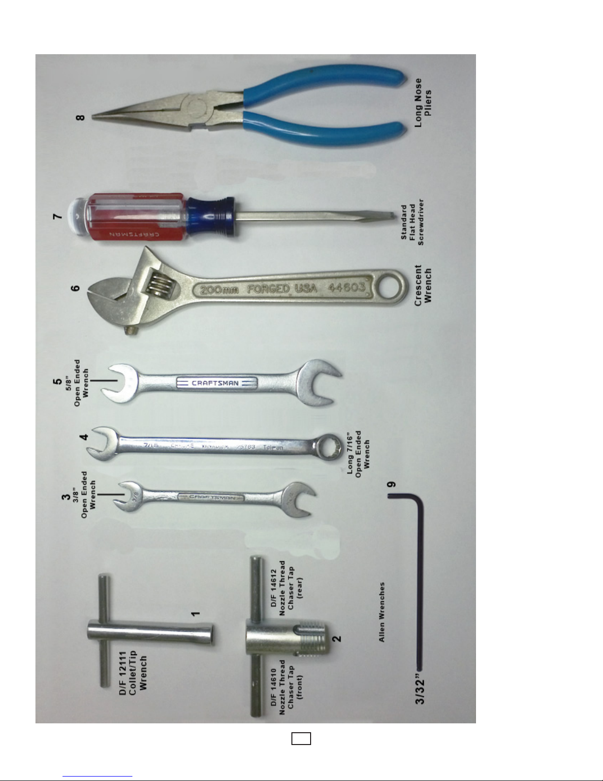
REQUIRED TOOLS LIST FOR DISASSEMBLY & ASSEMBLY
D/F 12111 Collet/Tip Wrench1. - This is the only tool that should ever be used to tighten the collet nut or the tip. Pressure should be 30
lbs., or as snug as hand tightened. Never use another wrench to apply more torque to this wrench.
D/F Nozzle Thread Chaser Taps (Front & Rear)2. - This is used to re-tap damaged threads that have been improperly cleaned or
cross threaded. Always blow out the nozzle and gas nozzle after changing gas cup or re-tapping. For more information on how to use
the nozzle thread chaser tap, use the following link: www.dfmachine.com/taps
3/8” Open Ended Wrench3. - This is used on the inner body’s gas hose tting to secure the gas hose to the torch’s inner body. A
crescent wrench could be used instead, but due to the large size of crescent wrenches, we prefer the smaller size of the open ended
wrenches. You never want to use excessive force by using too large of a wrench. You will use the Long 7/16” Open Ended Wrench for
the tting on the gas hose itself while using the 3/8” wrench to steady the inner body at the tting. (see #4)
Long 7/16” Open Ended Wrench4. - This is used to secure the gas hose to the torch’s inner body. (see #3)
5/8” Open Ended Wrench5. - This wrench is used to secure the adapter and jam nut that hold the current tip to the inner body. In your
left hand hold the inner body, and with your right hand thread up the adapter using the 5/8” Open Ended Wrench until it is tight. Now
place the same wrench on the jam nut and snug it up against the inner body. Keeping that wrench on the jam nut and placing it on
the table for force, take a second 5/8” Open Ended Wrench, place it on the adapter and push it down (counter-clockwise) securing
the adapter to the inner body.
Adjustable Crescent Wrench6. - A medium size adjustable crescent wrench could be used as well. CAUTION: Never use excessive
force with large wrenches, for you could twist or break parts.
Standard Flat Head Screwdriver7. - This is used to tighten or secure the torch’s body screw. Also, the screwdriver can be used to
straighten the contact tip if it is not aligned in the center of the gas cup or water-cooled nozzle CAUTION: This cannot be done unless
the spatter disc has been removed from the torch.
Long Nose Pliers8. - These are very handy when changing a slip-in contact tip.
3/32” Allen Wrench9.
This is used to secure the set screw that holds the casing in the torch’s inner body.A.
This is used on the inner body’s set screws to secure the power cable to the torch’s inner body.B.
6
REQUIRED TOOLS LIST FOR DISASSEMBLY & ASSEMBLY
7
 Loading...