

Page 1
INDUSTRIAL WASHER
MODEL T-900/950 ON-PREMISE
N-SERIES CONTROL
OPERATOR’S MANUAL
INSTALLATION & OPERATION
INSTRUCTIONS
Please read this information and retain for reference.
WARNING: THIS WASHER IS EQUIPPED WITH DEVICES AND FEATURES RELATING TO ITS SAFE
OPERATION. TO AVOID INJURY OR ELECTRICAL SHOCK, DO NOT PERFORM ANY SERVICING UNLESS
QUALIFIED TO DO SO.
IT IS THE RESPONSIBILITY OF THE OWNER TO CHECK THIS EQUIPMENT ON A FREQUENT
BASIS TO ASSURE ITS SAFE OPERATION.
A machine should NOT be allowed to operate if any of the following occur:
- Excessively high water level.
- If machine is not connected to a properly grounded circuit.
- If the door does not remain securely locked during the entire cycle.
- Vibration or shaking from an inadequate mounting or foundation.
WARNING - SAFETY PRECAUTIONS
- Always shut off power and water supply before servicing.
- Do not overload the washer.
- Do not open door when cylinder is in motion or it contains water.
- Do not bypass any safety devices of this washer.
- Do not use volatile or flammable substances in or near this washer.
- Keep all panels in place. They protect against shock and injury and add rigidity to the washer.
PREVENTIVE MAINTENANCE REQUIREMENTS
DAILY
- Check that the loading door remains securely locked and cannot be opened during an entire
cycle.
- Check the water connections for leaks.
- Clean the top, front, and sides of the cabinet to remove residue.
- Clean the soap dispenser and lid and check that all dispenser mounting screws are in-place and
tight.
- Check the drain valve for leaking and that it opens properly.
- Check the loading door for leaks. Clean the door seal of all foreign matter.
- Leave the loading door open to aerate the washer when not in use.
QUARTERLY
- Make sure the washer is inoperative by switching off the main power supply.
- Check the V-belts for wear and proper tension.
- Clean lint and other foreign matter from around motor.
- Check all water connections for leaks.
- Wipe and clean the inside of the washer and check that all electrical components are free of
moisture and dust.
- Remove and clean water inlet hose filters. Replace if necessary.
- Check anchor bolts. Retighten if necessary
IMPORTANT: Replace any and all panels that were removed to perform daily and/or quarterly
maintenance.
8514-244-001 REV PR page 1
Page 2
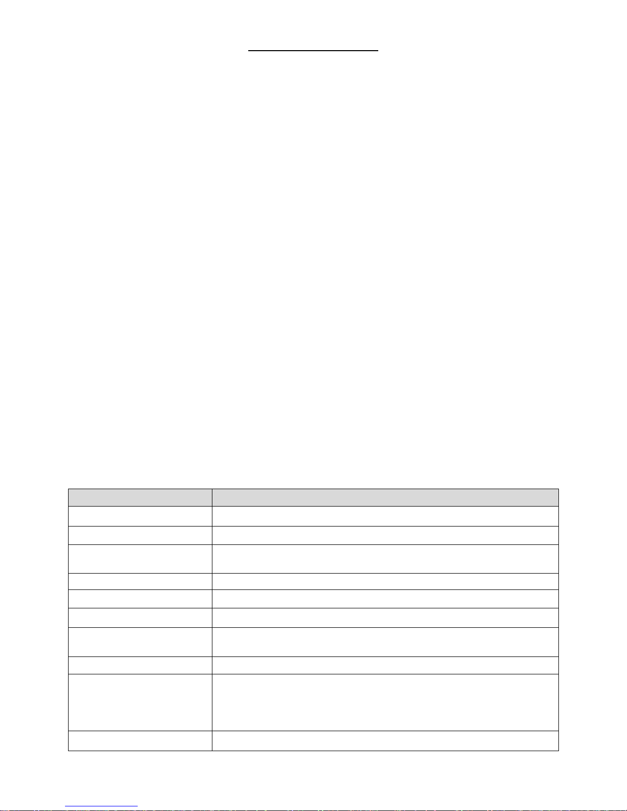
TABLE OF CONTENTS
MODEL
T-900/950 60 LB. WASHER
CAPACITY
60 LBS/9 CUBIC FT. (27.2 kg/255 L)
CYLINDER SIZE
30” DIA X 22” DEEP (76 cm X 55.9 cm)
ELECTRICAL
208-240 VAC, 60 HZ, 1 OR 3 PHASE; OR
208-240 VAC, 60 HZ, 3 PHASE ONLY (ELECTRIC HEAT MODEL)
DRIVE SYSTEM
SOFT START REVERSING INVERTER DRIVE
WASH SPEED
43 RPM
INTERMEDIATE EXTRACT
375 RPM (60 G’S)
FINAL EXTRACT
T-900: 484 RPM (100 G’S)
T-950: 685 RPM (200 G’S)
MACHINE CONTROL
PROGRAMMABLE COMPUTER UP TO 30 CYCLES
WATER INLET
SOLENOID OPERATED VALVES, 30-120 PSI
T-900: 2 VALVES, 9 GAL/MIN (34 L/MIN) EACH
T-950: 2 DUAL VALVES 9 GAL/MIN (34 L/MIN) EACH.
2 SINGLE VALVES 12 GAL/MIN (45 L/MIN) EACH.
DRAIN VALVE
3” (76 mm) DIAMETER
1 INSTALLATION INSTRUCTIONS .......................................................................... 3
1.1 FOUNDATION REQUIREMENTS ...................................................................... 3
1.2 MOUNTING .................................................................................................. 3
1.3 PLUMBING ................................................................................................... 7
1.4 DRAIN ......................................................................................................... 7
1.5 PROTECTIVE FILM ........................................................................................ 7
1.6 ELECTRICAL ................................................................................................. 7
1.6.1 INSTALLING THE ELECTRICAL CONNECTION ........................................... 8
1.6.2 FUSING REQUIREMENTS......................................................................... 8
1.6.3 CONTROLS TRANSFORMER (208-240V models only) ................................ 8
1.6.4 MAXIMUM SPIN SPEED ADJUSTMENT ...................................................... 9
1.7 INJECTION SOURCE CONNECTIONS ............................................................ 10
1.8 OPERATION CHECK .................................................................................... 10
2 WASHER OPERATION ....................................................................................... 11
2.1 CONTROL BUTTONS ................................................................................... 11
2.2 STARTING THE WASHER ............................................................................. 12
2.3 OPTIONAL SOAK ........................................................................................ 13
2.4 END OF CYCLE ........................................................................................... 13
2.5 SAFETY DOOR LOCK ................................................................................... 13
2.6 VARIABLE FREQUENCY DRIVE INDICATORS ................................................ 13
3 MACHINE PROGRAMMING INSTRUCTIONS ........................................................ 15
3.1 EDITING AN EXISTING CYCLE ..................................................................... 15
3.2 PROGRAMMING A NEW CYCLE .................................................................... 17
3.3 DEFAULT WASHER CYCLE PROGRAMS ......................................................... 18
3.4 RAPID ADVANCE MODE .............................................................................. 30
3.5 DIAGNOSTIC TEST CYCLE ........................................................................... 31
4 TROUBLESHOOTING ........................................................................................ 34
5 SERVICE AND PARTS ........................................................................................ 40
8514-244-001 REV PR page 2
Table 1: Washer Specifications
Page 3

1 INSTALLATION INSTRUCTIONS
All washers must be installed in accordance with all local, state and national
building, electrical, plumbing and other codes in effect in the area.
WARNING:
THESE INSTALLATION AND SERVICING INSTRUCTIONS ARE FOR USE
BY QUALIFIED PERSONNEL ONLY. TO AVOID INJURY AND ELECTRICAL
SHOCK, DO NOT PERFORM ANY SERVICING OTHER THAN THAT
CONTAINED IN THE OPERATING INSTRUCTIONS, UNLESS QUALIFIED.
1.1 FOUNDATION REQUIREMENTS
This machine is designed for use on or over bare concrete floor - not to be
used above combustible flooring, such as carpet or wood. The washer
must be securely bolted and grouted to a substantial concrete floor, or
mounted and grouted upon a suitable base that is securely bolted and
grouted to a substantial concrete floor.
CARE MUST BE TAKEN WITH ALL FOUNDATION WORK TO ENSURE A
STABLE UNIT INSTALLATION, ELIMINATING POSSIBILITIES OF
EXCESSIVE VIBRATION.
All installations require concrete floors 8 inches (203 mm) or thicker.
Anchor bolts or expansion anchors must be of a quality grade and a
minimum of 3/4 inch (19 mm) diameter. Six bolts are required to mount
the washer to the steel base or concrete pad. Mounting hardware is not
provided with the machine.
1.2 MOUNTING
A concrete pedestal or steel-mounting base that elevates the machine
approximately 4 inches (102 mm) above the floor level is recommended to
provide easy access to the loading door. Allow a minimum 24 inches (610
mm) of clearance behind the rear of the machine to provide access for
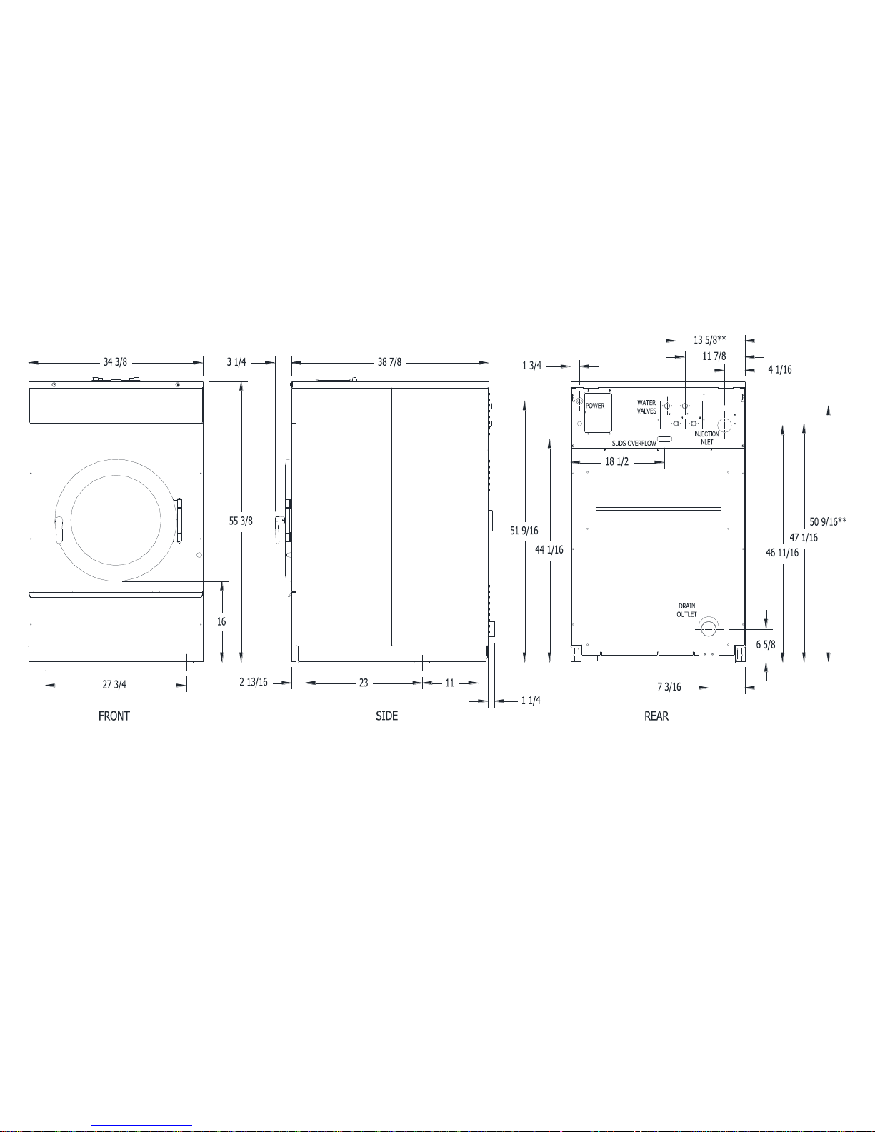
motor service. Refer to Figures Figure 1-1 and Figure 1-2 for machine
bolt-down dimensions. Contact a Dexter laundry equipment distributor for
recommended steel mounting bases.
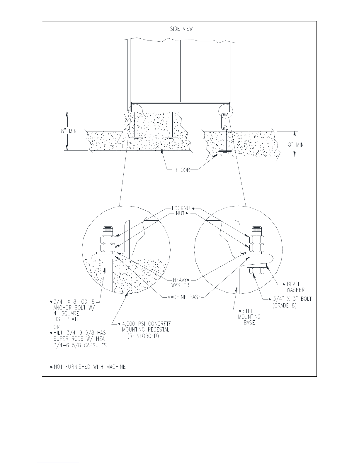
If an elevated concrete pedestal is desired, it should be embedded into
the existing floor. Anchor bolts should be 3/4" x 8" (19 mm x 200 mm),
grade 8 or better, headed by a 4 inch (10 cm) square fish plate and
should protrude 2 1/2” (64 mm) above the finished surface of the
pedestal.
EXPANSION ANCHORS ARE NOT RECOMMENDED FOR USE IN CONCRETE
PEDESTALS BECAUSE THE ANCHORS ARE TOO CLOSE TO AN EDGE,
CAUSING IT TO BREAK OUT.
Refer to Figures Figure 1-1 and Figure 1-3 for recommended concrete
pedestal dimensions. Refer to Figure Figure 1-4 for overall machine
mounting dimensions.
8514-244-001 REV PR page 3
Page 4
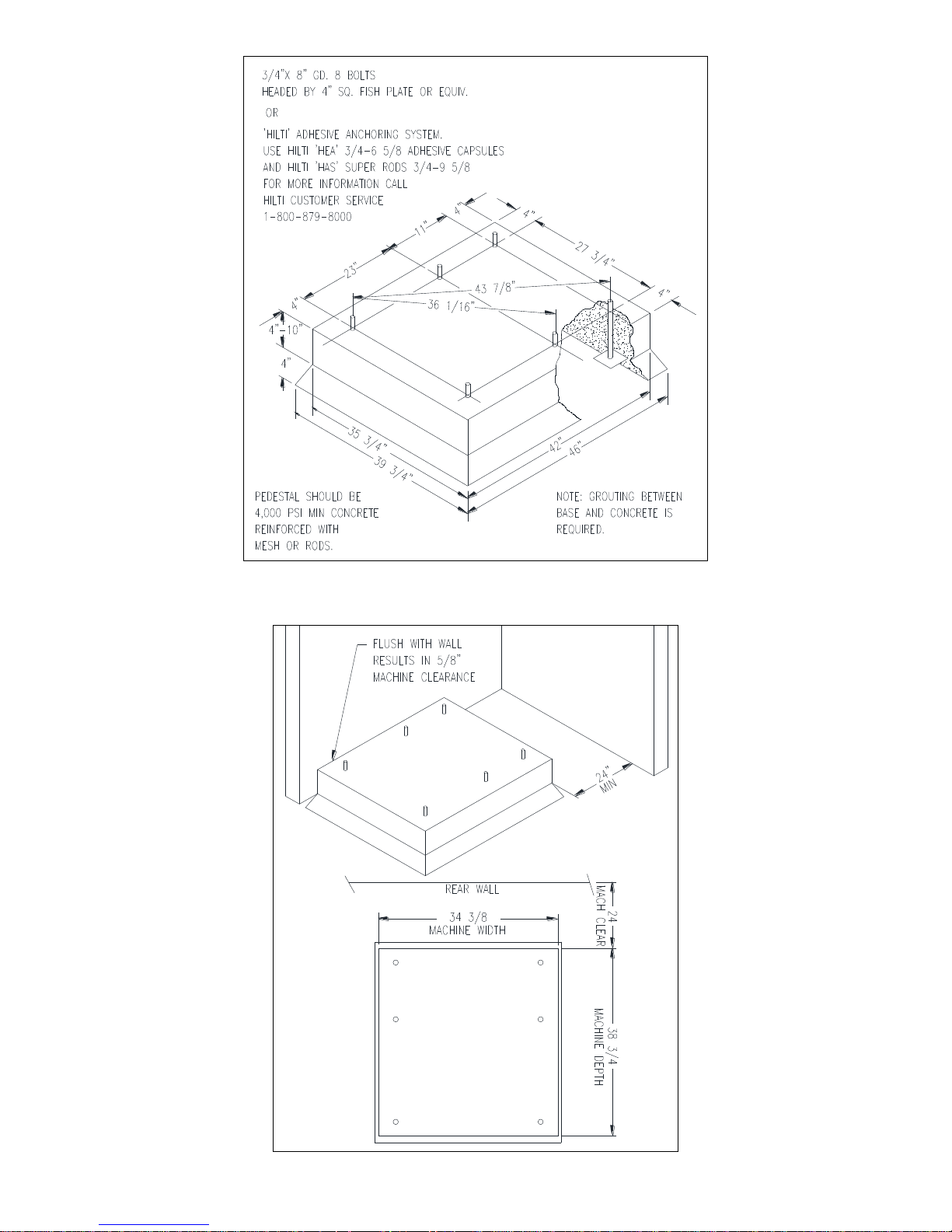
Figure 1-1: Concrete Pedestal Mounting
8514-244-001 REV PR page 4
Figure 1-2: Floor Outline
Page 5
8514-244-001 REV PR page 5
Figure 1-3: Machine Mounting Detail
Page 6
8514-244-001 REV PR page 6
Figure 1-4: T-900/950 Industrial Washer Mounting Diagram
**NOTE: Top water valves shown in Figure 1-4 are only on T-950 model.
Page 7
1.3 PLUMBING
Two (for T-900 models) or four (for T-950 models) 48 inch (1.22 m) water
supply hoses are provided with each machine. The threaded connections
on the hoses are ¾-11 ½ NHT.
Separate hot and cold water lines must be supplied to the machine,
maintaining 30 psi to 120 psi (207 kPa to 827 kPa) water flow pressure. A
140°F (60°C) hot water supply is recommended for best washing results.
Do not exceed 180°F (82°C) water temperature.
1.4 DRAIN
The drain outlet tube at the rear of the machine is 3 inches (76 mm) in
diameter. Any drain hose used must be lower than the drain valve to
assure proper draining.
1.5 PROTECTIVE FILM
The machine may have protective adhesive film on the front control panel
label area and on the front, top, and side stainless steel panels. The film
may be peeled off before putting the machine into service.
1.6 ELECTRICAL
The Dexter T-900/950 single/three-phase 208-240VAC 60 Hz and T900/950 three-phase 208-240VAC 60 Hz (with Electric Heater) washing
machines are intended to be permanently installed appliances. No power
cord is provided. The machine should be connected to an individual
branch circuit not shared by lighting or other equipment. The connection
should be sheathed in liquid tight flexible conduit, or equivalent, with
conductors of the proper size and insulation. A qualified technician should
make such connections in accordance with the wiring diagram with a
minimum 12 gauge wire. Select models with the electric heat option
require a minimum 6 gauge wire.
SHUT OFF POWER AND WATER BEFORE OPENING ANY SERVICE
WARNING:
PANELS.
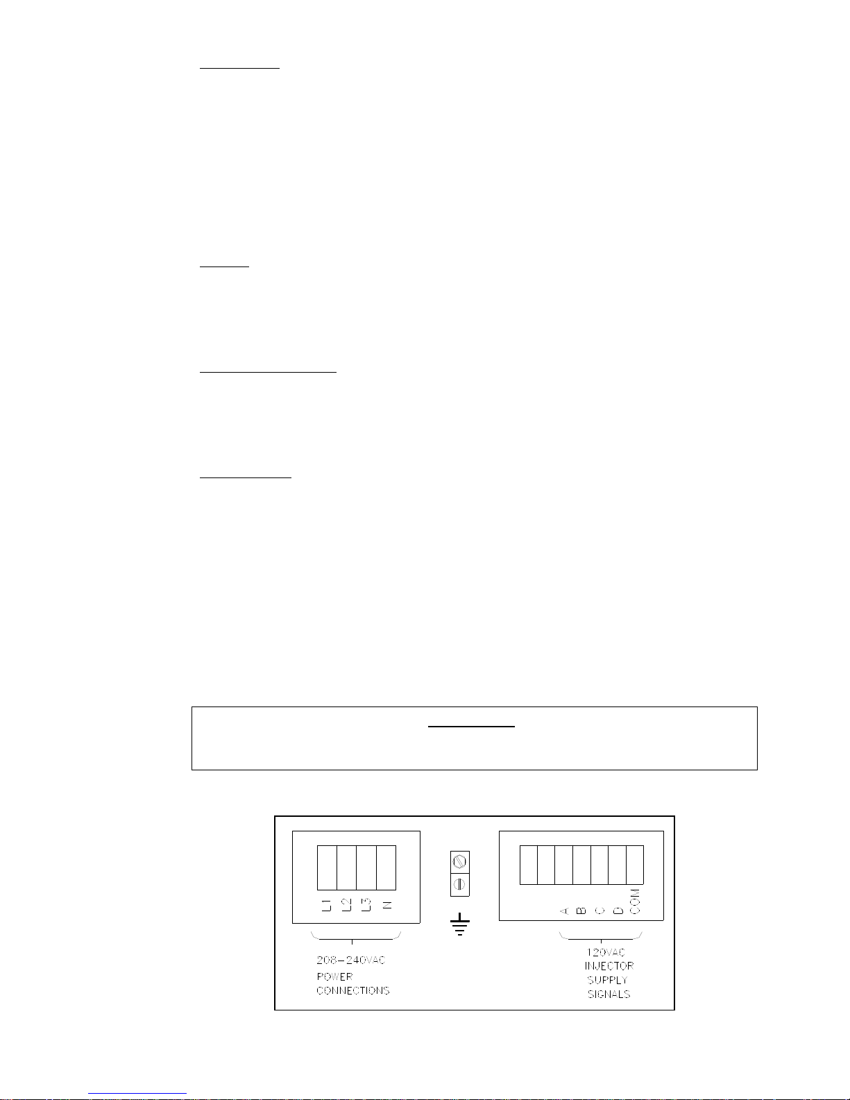
Figure 1-5: Electrical Connections and Chemical Supply Signals
8514-244-001 REV PR page 7
Page 8
1.6.1 INSTALLING THE ELECTRICAL CONNECTION
1.6.1.1 Disconnect all power to the washer.
1.6.1.2 Locate the power terminal block cover in the upper
left corner of the machine when viewed from the
back. Remove the screw and lift out the cover.
Connections are as shown in Figure 1-5.
1.6.1.3 If power is 208-240-3PH-60Hz, connect L1, L2, L3
and Ground. If there is a high leg, it must be
connected to L3.
1.6.1.4 If power is 208-240-1PH-60Hz, connect L1, L2 and
Ground.
NOTE: It is important that the grounding screw next to the power
terminal block TB-1 be connected to a good external ground.
1.6.2 FUSING REQUIREMENTS
Single- and Three -phase 208-240VAC 60 Hz models:
20 AMP TIME-DELAY (DUAL ELEMENT) FUSE (or equivalent circuit
breaker)
Three -phase 208-240VAC 60 Hz models with electric heat source:
60 AMP TIME-DELAY (DUAL ELEMENT) FUSE (or equivalent circuit
breaker)
1.6.3 CONTROLS TRANSFORMER (208-240V models only)
The controls transformer is located inside the control trough and
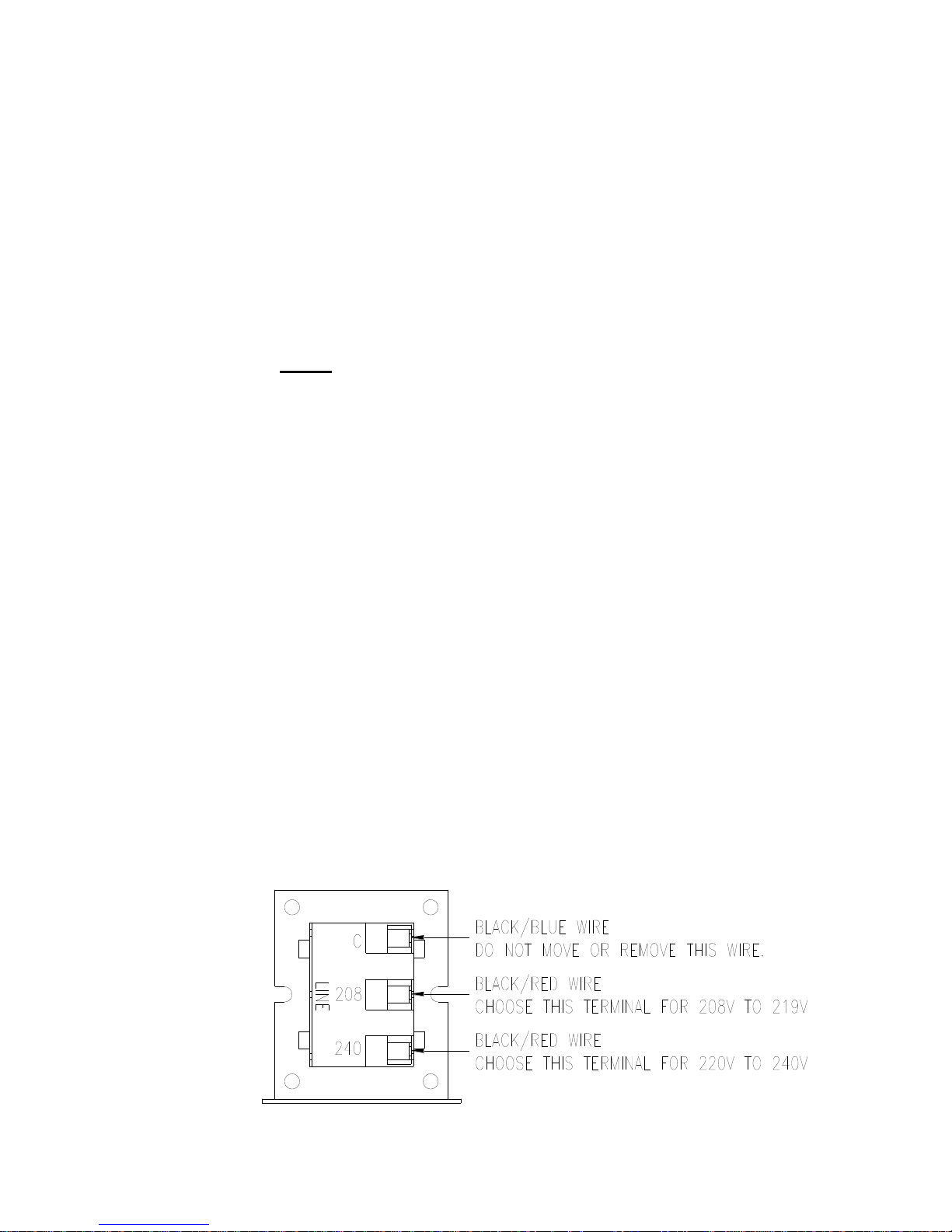
steps a range of 208 to 240 volts down to 115 volts. There are two
terminals on the controls transformer for the primary (incoming)
power. Use the terminal marked “208V” for power supplies
between 208 and 219 volts. Use the terminal marked “240V” for
power supplies between 220 and 240 volts. Refer to Figure 1-6 for
control transformer connections.
8514-244-001 REV PR page 8
Figure 1-6: Control Transformer Connections
Page 9
MI1 MI2 MI3 MI4 MI5 MI6
DCM
(Left)
DCM
(Right)
24V ACM AVI ACI 10V M01
60 G X X
80 G X X
100 G
100 G X X
140 G
200 G
T-600, T-900,
T-1200
Default Setting (No Jumper Required)
T-950, T-1450
REMOVE Brown Jumper between MI6/M01
Default Setting (With Factory Installed Brown Jumper)
N Series Washer
Model
Max Spin
Speed
Jumper Terminal Locations on Variable Frequency Drive (VFD)
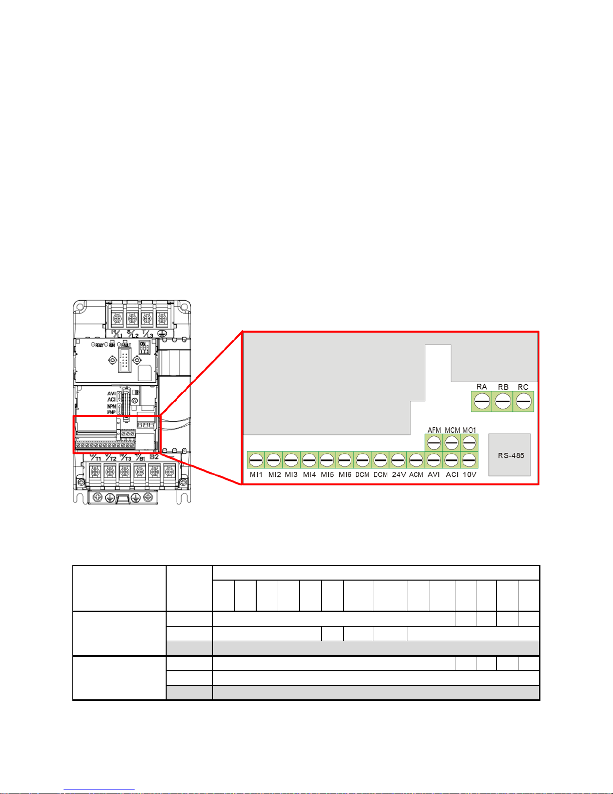
1.6.4 MAXIMUM SPIN SPEED ADJUSTMENT
If desired, the washer can be adjusted to limit the maximum
extract spin speed for all wash cycles.
To make this adjustment, a jumper wire must either be installed or
removed on the Variable Frequency Drive (VFD), depending on the
washer model and desired speed. This Dexter jumper part number
8220-057-036 (qty 1) is factory supplied on terminal points “10V”
and “RC”. Remove this jumper to make new jumper connections if
necessary. Refer to Figure 1-7 for the approximate location of the
control terminations on the Variable Frequency Drive (VFD) and
Table 2 for appropriate jumper connection points indicated with an
“X” for the desired maximum spin speed setting. If no adjustment
to default spin speed is desired, do not remove or add any wires on
VFD.
Figure 1-7: Control Terminations on Variable Frequency Drive
8514-244-001 REV PR page 9
Table 2: Spin Speed Adjustment Jumper Locations
Page 10
1.7 INJECTION SOURCE CONNECTIONS
Dexter
Recommended
Connections
Controller
Programmed
Signals
Injection
Terminal Block
Circuits
Detergent
1
A
Bleach
2 B Starch
3
C
Sour/Softener
4 D
5
A and B
6
C and D
0 None
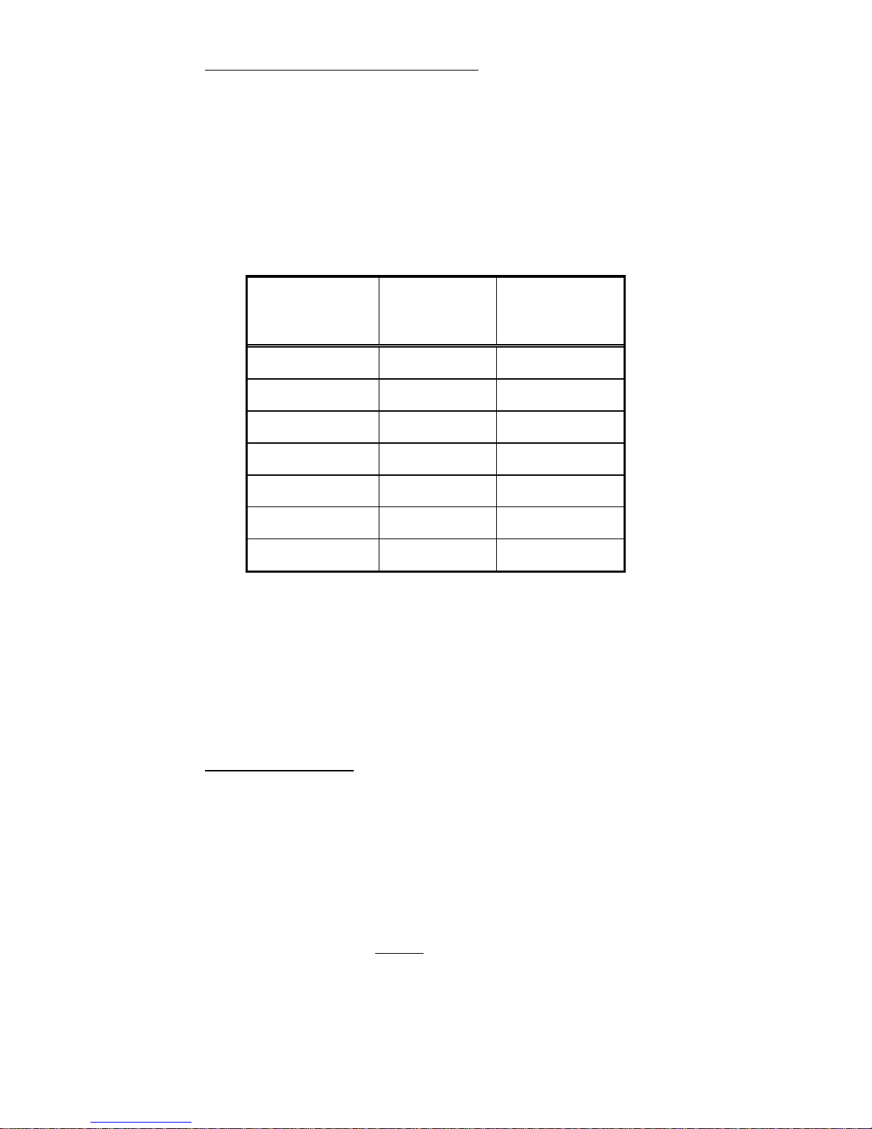
The washer control may be programmed to send six 120V output signals
for a chemical injection system of up to four chemical sources. There are
convenient electrical connection points for the injection pumps in the rear
of the machine, as shown in Figure 1-5. The four independent pumps can
be controlled through the signals A, B, C and D. The COM shown in Figure
1-5 is the common or return for these injection signals. For the injection
sources, program codes 0 through 6 and their respective terminal block
connections and combinations are as shown in Table 3.
Table 3: Injection Signal and Circuit Identification
Chemical Injection hoses are to be inserted into the injection inlet at the
upper right rear of the washer. These hoses should be inserted into the
round PVC pipe a minimum of 14" (35.5 cm) and a maximum of 18" (45.7
cm) to eliminate chemical buildup in the pipe and/or restrict water flow to
the tub. Secure the hoses as required.
1.8 OPERATION CHECK
After all mounting, plumbing and electrical work is completed, run through
each step of the diagnostic cycle (cycle #31), detailed in section 3.5, and
a complete wash cycle. Check for water leaks and verify proper operation.
During intermediate spin and final spin, the cylinder should turn in a
counterclockwise direction when viewed from the front of the machine.
If spin is clockwise, the T1 and T2 motor wires connecting to terminal T1
and T2 on the variable frequency drive should be swapped. Remove
power to the machine before opening service panels and swapping wires.
8514-244-001 REV PR page 10
Page 11
2 WASHER OPERATION
2.1 CONTROL BUTTONS
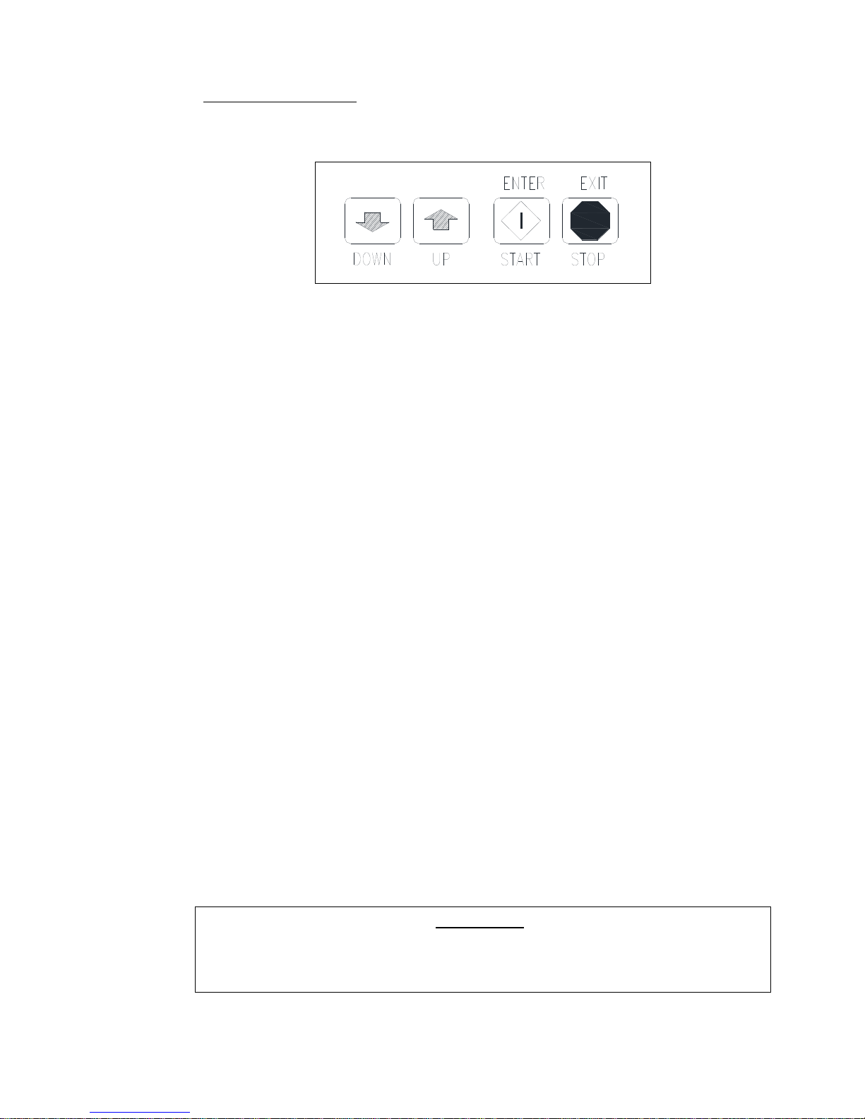
There are four (4) push buttons that control the washer operation. Each
button is shown in Figure 2-1, followed by an explanation of each button.
Figure 2-1: Washer Control Keypad Layout
SCROLL DOWN ARROW: Press momentarily / press and hold.
Scroll Down decreases the cycle number displayed by one each
time the switch is pressed. When the “DOWN” is held, the display
cycle numbers will continue to decrease until cycle #1 is reached at
which time the cycle number displayed will rollover to cycle #30
(cycle #31 while in Programming Mode).
SCROLL UP ARROW: Press momentarily / press and hold.
Scroll Up increases the cycle number displayed by one each time
the switch is pressed. When the “UP” is held, the display cycle
numbers will continue to increase until cycle #30 (cycle #31 while
in Programming Mode) is reached at which time the cycle number
displayed will rollover to cycle #1.
START/ENTER (green diamond): Press momentarily.
Starts the cycle shown on the display. If a wash cycle is
interrupted, pressing the “START” button will resume the cycle
from the point at which the cycle was interrupted.
STOP/EXIT (red octagon):
When pressed momentarily, it pauses the washer during the cycle.
All washer cycle information is retained, the door remains locked,
and the water remains in the tub.
When pressed and held for 3 seconds or longer, it stops the
washer, clears the cycle, drains the water, and unlocks the door
(up to 3 minutes after the washer is stopped). All washer cycle
information is cleared, and it is ready for the next wash cycle.
PRESSING AND HOLDING THE STOP IS AN EMERGENCY STOP
BUTTON. HOWEVER, THIS DOES NOT DISCONNECT THE
8514-244-001 REV PR page 11
WARNING:
MACHINE FROM THE INPUT POWER.
Page 12

2.2 STARTING THE WASHER
2.2.1 Turn on power to the washer.
2.2.2 Ensure washer is in “RUN” mode.
Locate the “ADVANCE/RUN/PROGRAM” key switch and key. The
current mode is indicated by the alignment of the key slot. If
washer is not in “RUN” mode, insert and turn the key to the “RUN”
position.
2.2.3 Load the laundry.
Place laundry loosely into the cylinder and latch the door securely.
Be sure laundry does not get caught between the door gasket and
tub front when closing the door. Maximum load is 60 pounds
clothes, dry weight. Do not load the washer with more than 60
pounds.
NOTE: To begin closing the door, the handle must be in the
horizontal position. After moving the door to the closed position,
the handle must be turned down to the vertical position in order to
latch the door for machine operation.
2.2.4 Select wash cycle.
Select the appropriate cycle number (1 through 30) for the type of
load being washed. See the default cycle descriptions in section
3.3. Use the “UP” and “DOWN” buttons to change the two digit
cycle number on the display to the desired cycle.
2.2.5 Add washing chemicals.
If not using a chemical injection system, add low sudsing powdered
detergent into the “DETERGENT” compartment of the automatic
dispenser on the top of the washer.
If liquid wash products are used in the “DETERGENT”
compartment, they must be added at the beginning of the wash
cycle.
If desired, add fabric softener to the “FABRIC SOFTENER”
compartment. Use the amount of fabric softener as recommended
by the manufacturer. This compartment will be flushed during the
“FINAL RINSE” segment of the cycle.
If the machine is set for pre-wash, washing products can be added
to the round opening of the dispenser or put in with the clothes
when loading the washing machine.
If bleach is desired, DO NOT place into dispenser until step 2.2.7.
2.2.6 Press “START”.
The door will lock and remain locked until the end of the cycle.
The cycle time remaining is displayed throughout the cycle. The
cycle number in operation can be displayed by pressing and holding
“START”, then press “UP”. The cycle number will be displayed as
8514-244-001 REV PR page 12
Page 13

long as these two buttons are pressed.
2.2.7 Add bleach if desired.
If you wish to manually add bleach during the cycle, add bleach in
the “BLEACH” compartment 3 minutes after the start of the
“WASH” cycle.
NOTE: Any additional washing chemicals may be added at the
appropriate time by pouring into the round opening on the top of
the washer.
2.3 OPTIONAL SOAK
At any time during the cycle, the red “STOP” button can be momentarily
pressed to pause the washer. All washer cycle information is retained and
the door remains locked. The washer will soak the load for 15 minutes
then agitate for 30 seconds. This will repeat until the cycle is started
again. This feature allows for an extended soak if required. The washer
cycle will continue when the “START” button is pressed.
NOTE: The selected cycle can be cleared at any time by pressing and
holding the “STOP” button for a minimum of 3 seconds.
2.4 END OF CYCLE
At the end of the cycle, the machine stops, the “END CYCLE” LED
illuminates, the alarm sounds, and the loading door unlocks. The door
can now be opened. Immediately remove contents of washer. Leave the
door open when the machine is not in use.
2.5 SAFETY DOOR LOCK
This machine is equipped with a safety door lock that locks the door when
the cycle is started until the cycle is complete. The door lock prevents
opening the door for up to 3 minutes if the power is interrupted during
the cycle.
2.6 VARIABLE FREQUENCY DRIVE INDICATORS
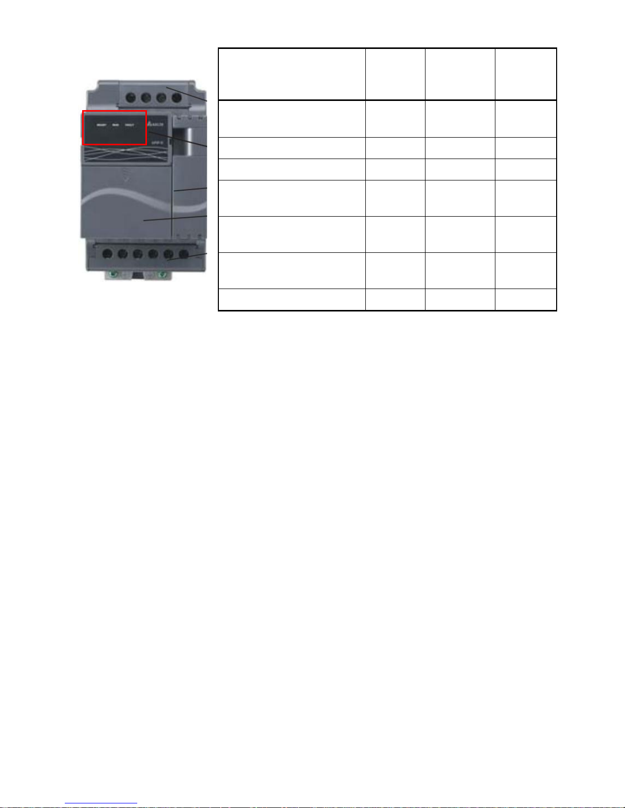
There are three small red LEDs located on the upper Variable Frequency
Drive (VFD) cover. They are labeled as “READY”, “RUN”, and “FAULT”
and can be used for troubleshooting. The definitions of the LEDs are
listed in Table 4 below.
8514-244-001 REV PR page 13
Page 14
Washer Condition
“READY”
LED
Status
“RUN”
LED Status
“FAULT”
LED
Status
Idle Mode
(No Cylinder Movement)
ON
OFF
OFF
Tumbling
ON
ON
OFF
Stop from Tumble
ON
FLASHING
OFF
Ramp to Intermediate or
Final Extract Spin
ON
ON
OFF
Spinning
(Intermediate or Final)
ON
ON
OFF
Stop from Spin
(Intermediate or Final)
ON
FLASHING
OFF
Faulted
ON
OFF
ON
Table 4: Variable Frequency Drive Indicators
8514-244-001 REV PR page 14
Page 15

3 MACHINE PROGRAMMING INSTRUCTIONS
This Dexter T-900/950 computer control OPL machine has 30 different selectable
cycles; 29 of the 30 cycles are preset with the most common industry
applications. See section 3.3 for complete cycle information. If these cycle
settings do not meet the required application, each cycle is reprogrammable by
the user simply and reliably.
Each cycle can have up to 9 baths including Flush, Prewash, Wash, Rinse 1, 2, 3,
4, 5 and Final Rinse/Extract. Each of those baths can be customized with various
defined settings including Cycle Time, Water Temperature, Water Level, Spin
Time, and Injection Source. Programming can be accomplished manually using
the machine controls. Please read below for manual programming instructions.
NOTE: It is recommended when changes are made to one or more of the preset
programs that the cycle number and the changes be documented for later
reference. Blank cycle tables have been provided at the end of section 3.3.
3.1 EDITING AN EXISTING CYCLE
3.1.1 Turn on the power to the washer.
Washer must be in idle mode to program.
3.1.2 Ensure washer is in “PROGRAM” mode.
Locate the “ADVANCE/RUN/PROGRAM” key switch and key. The
current mode is indicated by the alignment of the key slot. If
washer is not in “PROGRAM” mode, insert and turn the key to the
“PROGRAM” position.
The display will show a two digit cycle number. The “PROGRAM
MODE” LED and “SELECT CYCLE” LED illuminate.
3.1.3 Select cycle to alter.
Press the “DOWN” or “UP” buttons on the keypad until the desired
cycle number, 1 through 30, is displayed. Do not select cycle 31.
3.1.4 Press “ENTER” to enter the cycle.
Once pressed, the first of the nine bath LEDs will illuminate. The
“SELECT CYCLE” LED is turned off.
3.1.5 Select a bath to alter.
Press the “UP” and “DOWN” buttons to select a bath. The bath
indicator lights, shown in Figure 3-1, illuminate to indicate which
bath is being selected.
There are 9 available baths to program: FLUSH, PRE WASH, WASH,
RINSE1, RINSE 2, RINSE 3, RINSE 4, RINSE 5 and FINAL RINSE.
8514-244-001 REV PR page 15
Figure 3-1: Bath Indicator Lights
Page 16
3.1.6 Press “ENTER” to display the settings.
SETTING
OPTIONS
Cycle Time1
Two-digit amount of time for bath tumble in minutes.
- 00 to 30 minutes for Flush, Prewash, Wash,
Rinse 1, 2, 3, 4 and 5. If the time is set to 00,
then the bath will be eliminated from the
cycle.
- 01 to 30 minutes for Final Rinse.
Water
Temperature
2
HH for hot water
CH for warm water
CC for cold water
EE for no water3
Water Level
LO for low level
HI for high level
Injection
Source3
Two-digit code indicating injector signal(s), 00 to 06.
Spin Time
Two-digit amount of time for spin in minutes.
- 00 to 10 minutes for Flush, Prewash, Wash,
Rinse 1, 2, 3, 4, and 5
- 01 to 10 minutes for Final Rinse
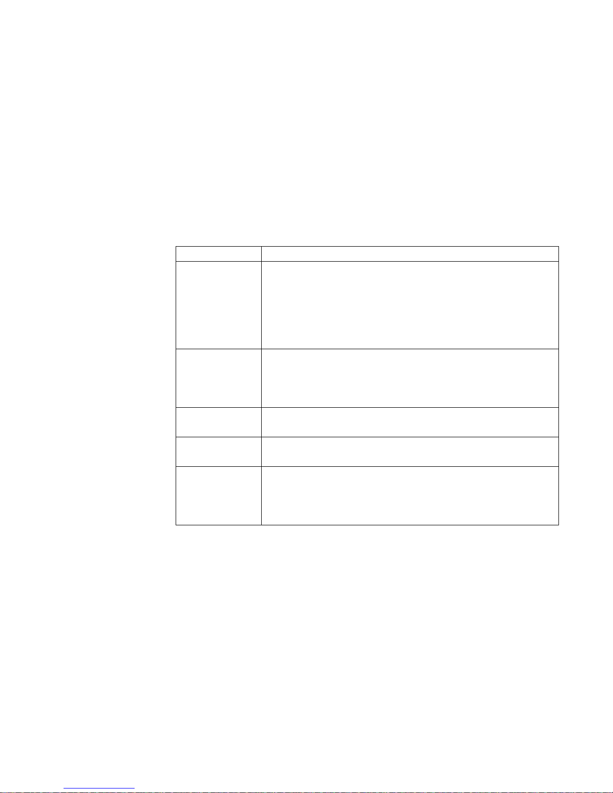
Available settings to alter in each bath are Cycle Time, Water
Temperature, Water Level, Injection Source, and Spin Time.
3.1.7 Input settings.
The first setting to alter is the Cycle Time as indicated by the
“CYCLE TIME” LED. Use the “DOWN” and “UP” keys to set the
desired time in minutes and press “ENTER” to advance to the next
setting. If no change is desired, press “ENTER” to advance to the
next setting.
Repeat process for each setting. Each bath setting can be
programmed with the options shown in Table 5.
Table 5: Bath Program Settings
1
Cycle times are approximate and do not include fill time from empty to low
water level. However, fill time from low to high water level is included as
computer operates during this period.
2
For models with electric heat, entering a temperature value of 20°-90°C will
result in a heated bath if temperature of fill water is less than programmed
temperature.
3
Codes for injections sources are defined in Table 3. When “EE” is selected in
the Water Temperature setting, the electronic controller prohibits injection
signals. The programmed injection source value is ignored.
When the final desired Spin Time setting is selected, press
8514-244-001 REV PR page 16
“ENTER”. The Spin Time is entered, The “SPIN TIME” LED turns
off, and the editing of the selected bath is complete. The next
sequential bath light is immediately illuminated.
Page 17

3.1.8 Program another bath.
If desired, repeat steps 3.1.5 through 3.1.7 to program another
bath. Otherwise, continue to the next step.
3.1.9 Program another cycle.
To program a different cycle when any of the nine bath LEDs are
illuminated, press the “EXIT” button. The “SELECT CYCLE” LED will
immediately illuminate. The programming changes made prior to
the program exit are retained and the cycle is updated.
NOTE: When the “FINAL RINSE” bath programming is complete,
the cycle programming is also complete and the “SELECT CYCLE”
LED will immediately illuminate. Another cycle can be programmed.
If desired, repeat steps 3.1.3 through 3.1.8 to program another
cycle. Otherwise, continue to the next step to end programming.
3.1.10 End programming mode.
When the “SELECT CYCLE” LED is illuminated, turn the key to the
“RUN” position. The “PROGRAM MODE” LED will turn off.
NOTE: The Wash Cycle programming mode will automatically exit and
return to the Idle mode if no buttons are pressed for one minute.
3.2 PROGRAMMING A NEW CYCLE
The instructions for entering a new cycle are the same as the instructions
in section 3.1. To program a new cycle, an existing cycle number
between 1 and 30 must be overridden with a custom program. Cycle 31
cannot be reprogrammed. Only the cycle baths required need to be
programmed. Any baths, except FINAL RINSE, can be skipped by
entering a “00” time value in the Cycle Time for each unused bath.
8514-244-001 REV PR page 17
Page 18
3.3 DEFAULT WASHER CYCLE PROGRAMS
Application
Cycle #
Recommendation Description
Shirt/Laundry
1
Shirts – No Starch
2 Shirts – Starch
Hotel/Motel
3
White Sheets
4 White Pillowcases
5 White Towels, Bath Mats, Wash Cloths
6 Colored Sheets and Towels
7 Delicate Wash
8 Housekeeping Rags and Mops
9 Housekeeping Uniforms
10
Stain Treatment
11
Reclaim Part 1
12
Reclaim Part 2
Health Care
13
Sheets and Pillowcases
14
Towels
15
Diapers and Pads
16
Personals
17
Delicate
Food & Beverage
18
White (Cotton/Blend) Table Linen
19
Colored (Cotton/Blend) Table Linen
20
White 100% Polyester Table Linen
21
Colored 100% Polyester Table Linen
22
White Chef Coats
23
Kitchen and Maintenance Rags
24
White/Colored (Cotton/Blend) Table Linen
25
White/Colored 100% Polyester Table Linen
26
White Chef Coats
27
Kitchen and Maintenance Rags
Other
28
Oxygen Bleach – Terry
29
Oxygen Bleach – Terry (No iron)
Test
30
Test Injection Signals and Pressure Switch
31
Test Diagnostic (not customizable)
The factory default cycles pre-programmed into the washer are listed with
each bath and setting option in this section. All wash cycles can be
reprogrammed, refer to section 3.1 for instructions.
To reset all customized programs back to original factory default settings,
refer to section 3.5 and complete step 14 of the Test Diagnostic Cycle.
Table 6: Default Washer Cycle Programs
8514-244-001 REV PR page 18
Page 19
Cycle 1 Shirts - No Starch (Shirt/Laundry)
Bath
Bath Cycle
Time (min.)
Water
Temp.
Water
Level
Injection Source
Spin Time
(min.)
Flush
Prewash
Wash
12
HH
LO
5 (Detergent/Bleach)
Rinse 1
2
CH
HI
Rinse 2
2
CH
HI
Rinse 3
2
CH
HI
Rinse 4
Rinse 5
Final Rinse
4
CH
LO 3
Bath
Bath Cycle
Time (min.)
Water
Temp.
Water
Level
Injection Source
Spin Time
(min.)
Flush
Prewash
Wash
12
HH
LO
5 (Detergent/Bleach)
Rinse 1
2
CH
HI
Rinse 2
2
CH
HI
Rinse 3
2
CH
HI
Rinse 4
Rinse 5
Final Rinse
7
CH
LO
3 (Starch)
3
Bath
Bath Cycle
Time (min.)
Water
Temp.
Water
Level
Injection Source
Spin Time
(min.)
Flush
Prewash
7
HH
LO
1 (Detergent)
Wash
7
HH
LO
2 (Bleach)
Rinse 1
2
CH
HI 1
Rinse 2
2
CH
HI
Rinse 3
Rinse 4
Rinse 5
Final Rinse
4
CH
LO
4 (Sour/Softener)
4
Cycle 2 Shirts - Starch (Shirt/Laundry)
Cycle 3 White Sheets (Hotel/Motel)
8514-244-001 REV PR page 19
Page 20
Cycle 4 White Pillowcases (Hotel/Motel)
Bath
Bath Cycle
Time (min.)
Water
Temp.
Water
Level
Injection Source
Spin Time
(min.)
Flush
7
HH
LO
1 (Detergent)
Prewash
1
HH
HI
Wash
7
HH
LO
2 (Bleach)
Rinse 1
2
CH
HI 1
Rinse 2
2
CH
HI
Rinse 3
Rinse 4
Rinse 5
Final Rinse
4
CH
LO
4 (Sour/Softener)
4
Bath
Bath Cycle
Time (min.)
Water
Temp.
Water
Level
Injection Source
Spin Time
(min.)
Flush
7
HH
LO
1 (Detergent)
Prewash
1
HH
HI
Wash
7
HH
LO
2 (Bleach)
Rinse 1
2
CH
HI 1
Rinse 2
2
CH
HI
Rinse 3
Rinse 4
Rinse 5
Final Rinse
4
CH
LO
4 (Sour/Softener)
5
Bath
Bath Cycle
Time (min.)
Water
Temp.
Water
Level
Injection Source
Spin Time
(min.)
Flush
Prewash
Wash
7
HH
LO
5 (Detergent/Bleach)
Rinse 1
2
HH
HI
Rinse 2
2
CH
HI 1
Rinse 3
2
CH
HI
Rinse 4
Rinse 5
Final Rinse
4
CH
LO
4 (Sour/Softener)
4
Cycle 5 White Towels (Hotel/Motel)
Cycle 6 Color Sheets (Hotel/Motel)
8514-244-001 REV PR page 20
Page 21
Cycle 7 Delicate (Hotel/Motel)
Bath
Bath Cycle
Time (min.)
Water
Temp.
Water
Level
Injection Source
Spin Time
(min.)
Flush
Prewash
Wash
8
CH
HI
5 (Detergent/Bleach)
Rinse 1
2
HH
HI
Rinse 2
2
CH
HI
Rinse 3
2
CH
HI
Rinse 4
Rinse 5
Final Rinse
4
CH
LO
4 (Sour/Softener)
4
Bath
Bath Cycle
Time (min.)
Water
Temp.
Water
Level
Injection Source
Spin Time
(min.)
Flush
3
CH
HI
Prewash
Wash
2
CH
HI
Rinse 1
2
CH
HI
Rinse 2
7
HH
LO
1 (Detergent)
Rinse 3
2
HH
HI
Rinse 4
7
HH
LO
2 (Bleach)
Rinse 5
2
CH
HI 1
Final Rinse
2
CH
HI 5
Bath
Bath Cycle
Time (min.)
Water
Temp.
Water
Level
Injection Source
Spin Time
(min.)
Flush
2
CH
HI
Prewash
Wash
7
HH
LO
1 (Detergent)
Rinse 1
7
HH
LO
2 (Bleach)
Rinse 2
2
CH
HI 1
Rinse 3
2
CH
HI
Rinse 4
Rinse 5
Final Rinse
4
CH
LO
4 (Sour/Softener)
4
Cycle 8 Rags and Mops (Hotel/Motel)
Cycle 9 Uniforms (Hotel/Motel)
8514-244-001 REV PR page 21
Page 22
Cycle 10 Stain Treatment – Chlorine Bleach (Hotel/Motel)
Bath
Bath Cycle
Time (min.)
Water
Temp.
Water
Level
Injection Source
Spin Time
(min.)
Flush
Prewash
Wash
30
HH
LO
5 (Detergent/Bleach)
Rinse 1
2
HH
HI
Rinse 2
2
HH
HI
Rinse 3
2
CH
HI 1
Rinse 4
Rinse 5
Final Rinse
2
CH
HI 4
Bath
Bath Cycle
Time (min.)
Water
Temp.
Water
Level
Injection Source
Spin Time
(min.)
Flush
Prewash
Wash
20
HH
LO
Manual
Rinse 1
3
HH
HI
Rinse 2
Rinse 3
Rinse 4
Rinse 5
Final Rinse
3
HH
HI 1
Bath
Bath Cycle
Time (min.)
Water
Temp.
Water
Level
Injection Source
Spin Time
(min.)
Flush
Prewash
3
HH
HI
Wash
20
HH
LO
Manual
Rinse 1
3
HH
HI
Rinse 2
3
HH
HI
Rinse 3
10
HH
LO
2 (Bleach)
Rinse 4
3
HH
HI 1
Rinse 5
Final Rinse
3
CH
HI 4
Cycle 11 Reclaim Part 1 (Hotel/Motel)
Cycle 12 Reclaim Part 2 (Hotel/Motel)
8514-244-001 REV PR page 22
Page 23
Cycle 13 Sheets and Pillowcases (Health Care)
Bath
Bath Cycle
Time (min.)
Water
Temp.
Water
Level
Injection Source
Spin Time
(min.)
Flush
3
CH
HI
Prewash
2
CH
HI
Wash
7
HH
LO
1 (Detergent)
Rinse 1
7
HH
LO
2 (Bleach)
Rinse 2
2
CH
HI 1
Rinse 3
2
CH
HI
Rinse 4
Rinse 5
Final Rinse
4
CH
LO
4 (Sour/Softener)
4
Bath
Bath Cycle
Time (min.)
Water
Temp.
Water
Level
Injection Source
Spin Time
(min.)
Flush
3
CH
HI
Prewash
2
CH
HI
Wash
7
HH
LO
1 (Detergent)
Rinse 1
1
HH
HI
Rinse 2
7
HH
LO
2 (Bleach)
Rinse 3
2
CH
HI 1
Rinse 4
2
CH
HI
Rinse 5
Final Rinse
4
CH
LO
4 (Sour/Softener)
5
Bath
Bath Cycle
Time (min.)
Water
Temp.
Water
Level
Injection Source
Spin Time
(min.)
Flush
3
CH
HI
Prewash
2
CH
HI
Wash
2
CH
HI
Rinse 1
7
HH
LO
1 (Detergent)
Rinse 2
2
HH
HI
Rinse 3
7
HH
LO
2 (Bleach)
Rinse 4
2
CH
HI 1
Rinse 5
2
CH
HI
Final Rinse
4
CH
LO
4 (Sour/Softener)
4
Cycle 14 Towels (Health Care)
Cycle 15 Diapers (Health Care)
8514-244-001 REV PR page 23
Page 24
Cycle 16 Personals (Health Care)
Bath
Bath Cycle
Time (min.)
Water
Temp.
Water
Level
Injection Source
Spin Time
(min.)
Flush
3
CH
HI
Prewash
Wash
7
HH
LO
5 (Detergent/Bleach)
Rinse 1
2
HH
HI
Rinse 2
2
CH
HI
Rinse 3
2
CH
HI
Rinse 4
Rinse 5
Final Rinse
4
CH
LO
4 (Sour/Softener)
4
Bath
Bath Cycle
Time (min.)
Water
Temp.
Water
Level
Injection Source
Spin Time
(min.)
Flush
2
CH
HI
Prewash
Wash
7
CH
HI
5 (Detergent/Bleach)
Rinse 1
2
CH
HI
Rinse 2
2
CH
HI
Rinse 3
2
CH
HI
Rinse 4
Rinse 5
Final Rinse
4
CH
HI
4 (Sour/Softener)
3
Bath
Bath Cycle
Time (min.)
Water
Temp.
Water
Level
Injection Source
Spin Time
(min.)
Flush
2
CH
HI
Prewash
Wash
10
HH
LO
1 (Detergent)
Rinse 1
2
HH
HI
Rinse 2
7
HH
LO
2 (Bleach)
Rinse 3
2
CH
HI 1
Rinse 4
2
CH
HI
Rinse 5
Final Rinse
4
CH
LO
6 (Sour/Starch)
4
Cycle 17 Delicate (Health Care)
Cycle 18 White Cotton Table Linen (Food & Beverage)
8514-244-001 REV PR page 24
Page 25
Cycle 19 Colored Cotton Table Linen (Food & Beverage)
Bath
Bath Cycle
Time (min.)
Water
Temp.
Water
Level
Injection Source
Spin Time
(min.)
Flush
2
CH
HI
Prewash
Wash
10
HH
LO
1 (Detergent)
Rinse 1
7
HH
LO
2 (Bleach)
Rinse 2
2
CH
HI 1
Rinse 3
2
CH
HI
Rinse 4
Rinse 5
Final Rinse
4
CH
LO
6 (Sour/Starch)
4
Bath
Bath Cycle
Time (min.)
Water
Temp.
Water
Level
Injection Source
Spin Time
(min.)
Flush
2
CH
HI
Prewash
Wash
10
HH
LO
1 (Detergent)
Rinse 1
2
HH
HI
Rinse 2
7
HH
LO
2 (Bleach)
Rinse 3
2
CH
HI
Rinse 4
2
CH
HI
Rinse 5
Final Rinse
4
CH
LO
6 (Sour/Starch)
4
Bath
Bath Cycle
Time (min.)
Water
Temp.
Water
Level
Injection Source
Spin Time
(min.)
Flush
2
CH
HI
Prewash
Wash
10
HH
LO
1 (Detergent)
Rinse 1
7
HH
LO
2 (Bleach)
Rinse 2
2
CH
HI
Rinse 3
2
CH
HI
Rinse 4
Rinse 5
Final Rinse
4
CH
LO
6 (Sour/Starch)
4
Cycle 20 White 100% Polyester Table Linen (Food & Beverage)
Cycle 21 Colored 100% Polyester Table Linen (Food & Beverage)
8514-244-001 REV PR page 25
Page 26
Cycle 22 White Chef Coats (Food & Beverage)
Bath
Bath Cycle
Time (min.)
Water
Temp.
Water
Level
Injection Source
Spin Time
(min.)
Flush
5
HH
LO
1 (Detergent)
Prewash
1
HH
HI
Wash
8
HH
LO
1 (Detergent)
Rinse 1
2
HH
HI
Rinse 2
7
HH
LO
2 (Bleach)
Rinse 3
2
CH
HI 1
Rinse 4
2
CH
HI
Rinse 5
Final Rinse
4
CH
LO
4 (Sour)
4
Bath
Bath Cycle
Time (min.)
Water
Temp.
Water
Level
Injection Source
Spin Time
(min.)
Flush
5
HH
LO
1 (Detergent)
Prewash
2
HH
HI
Wash
8
HH
LO
1 (Detergent)
Rinse 1
2
HH
HI 1
Rinse 2
7
HH
LO
2 (Bleach)
Rinse 3
2
CH
HI 1
Rinse 4
Rinse 5
Final Rinse
2
CH
HI 5
Bath
Bath Cycle
Time (min.)
Water
Temp.
Water
Level
Injection Source
Spin Time
(min.)
Flush
2
CH
HI
Prewash
Wash
10
HH
LO
5 (Detergent/Bleach)
Rinse 1
1
HH
HI
Rinse 2
2
HH
HI 1
Rinse 3
2
CH
HI
Rinse 4
2
CH
HI
Rinse 5
Final Rinse
4
CH
LO
6 (Sour/Starch)
4
Cycle 23 Kitchen and Maintenance Rags (Food & Beverage)
Cycle 24 White/Colored (Cotton/Blend) Table Linen (Food & Beverage)
8514-244-001 REV PR page 26
Page 27
Cycle 25 White/Colored 100% Polyester Table Linen (Food & Beverage)
Bath
Bath Cycle
Time (min.)
Water
Temp.
Water
Level
Injection Source
Spin Time
(min.)
Flush
2
CH
HI
Prewash
Wash
10
HH
LO
5 (Detergent/Bleach)
Rinse 1
1
HH
HI
Rinse 2
2
HH
LO
Rinse 3
2
CH
HI
Rinse 4
2
CH
HI
Rinse 5
Final Rinse
4
CH
LO
6 (Sour/Starch)
4
Bath
Bath Cycle
Time (min.)
Water
Temp.
Water
Level
Injection Source
Spin Time
(min.)
Flush
5
HH
LO
1 (Detergent)
Prewash
1
HH
HI
Wash
10
HH
LO
5 (Detergent/Bleach)
Rinse 1
2
HH
HI
Rinse 2
2
CH
HI 1
Rinse 3
2
CH
HI
Rinse 4
Rinse 5
Final Rinse
4
CH
HI
4 (Sour/Softener)
4
Bath
Bath Cycle
Time (min.)
Water
Temp.
Water
Level
Injection Source
Spin Time
(min.)
Flush
5
HH
LO
1 (Detergent)
Prewash
2
HH
HI
Wash
10
HH
LO
5 (Detergent/Bleach)
Rinse 1
1
HH
HI
Rinse 2
2
HH
HI 1
Rinse 3
2
CH
HI
Rinse 4
Rinse 5
Final Rinse
2
CH
HI 5
Cycle 26 White Chef Coats (Food & Beverage)
Cycle 27 Kitchen Rags (Food & Beverage)
8514-244-001 REV PR page 27
Page 28
Cycle 28 Oxygen Bleach Terry (Other)
Bath
Bath Cycle
Time (min.)
Water
Temp.
Water
Level
Injection Source
Spin Time
(min.)
Flush
3
CH
HI
Prewash
2
CH
HI
Wash
10
HH
LO
5 (Detergent/Bleach)
Rinse 1
2
HH
HI
Rinse 2
2
CH
HI 1
Rinse 3
2
CH
HI
Rinse 4
Rinse 5
Final Rinse
4
CH
LO
4 (Sour/Softener)
3
Bath
Bath Cycle
Time (min.)
Water
Temp.
Water
Level
Injection Source
Spin Time
(min.)
Flush
3
CH
HI
Prewash
2
CH
HI
Wash
10
HH
LO
5 (Detergent/Bleach)
Rinse 1
2
HH
HI
Rinse 2
2
CH
HI 1
Rinse 3
2
CH
HI
Rinse 4
Rinse 5
Final Rinse
4
CH
LO
4 (Sour/Softener)
5
Bath
Bath Cycle
Time (min.)
Water
Temp.
Water
Level
Injection Source
Spin Time
(min.)
Flush
2
CH
LO
1 (Detergent)
Prewash
Wash
7
HH
HI
2 (Bleach)
Rinse 1
2
CH
HI
3 (Starch)
Rinse 2
2
CH
HI
4 (Sour/Softener)
Rinse 3
2
CH
HI
Rinse 4
Rinse 5
Final Rinse
4
CC
HI 3
Cycle 29 Oxygen Bleach Terry - No Iron (Other)
Cycle 30 Pressure Switch and Injection Signals (Test)
8514-244-001 REV PR page 28
Page 29
Cycle _____ Description _________________________________
Bath
Bath Cycle
Time (min.)
Water
Temp.
Water
Level
Injection Source
Spin Time
(min.)
Flush
Prewash
Wash
Rinse 1
Rinse 2
Rinse 3
Rinse 4
Rinse 5
Final Rinse
Bath
Bath Cycle
Time (min.)
Water
Temp.
Water
Level
Injection Source
Spin Time
(min.)
Flush
Prewash
Wash
Rinse 1
Rinse 2
Rinse 3
Rinse 4
Rinse 5
Final Rinse
Bath
Bath Cycle
Time (min.)
Water
Temp.
Water
Level
Injection Source
Spin Time
(min.)
Flush
Prewash
Wash
Rinse 1
Rinse 2
Rinse 3
Rinse 4
Rinse 5
Final Rinse
Cycle _____ Description _________________________________
Cycle _____ Description _________________________________
8514-244-001 REV PR page 29
Page 30

3.4 RAPID ADVANCE MODE
Rapid Advance mode is a key-controlled override to interrupt the current
cycle, drain the water, and advance to the next mode of the wash cycle,
including Pre Wash, Wash, Rinse 1, Rinse 2, Rinse 3, Rinse 4, Rinse 5, and
Final Rinse. The indicator lights will show to which segment the cycle has
been advanced.
To enter the Rapid Advance mode, insert the key into the Rapid
Advance/Run/Program lock and turn the key counter-clockwise (CCW).
The Rapid Advance mode must be entered during a cycle. If the cycle has
not yet started, press the “DOWN” button or the “UP” button to choose a
cycle and then the “START” button to begin the cycle.
To advance to the next step in the cycle, press both the “UP” and “START”
buttons at the same time. The display will show “Ad” (advance).
If advancing during a bath, all water valves will turn off and the drain will
open until the “open drain” step is completed. The cycle will then
continue to the next bath or to the spin of the current bath if the
programming includes spin time.
If advancing during a chemical injection of a bath or after a chemical
injection of the bath but before the low water level is reached, the injector
will turn off and the hot and the cold water valves to the tub will turn on
until the low water level is reached or for 30 seconds, whichever comes
first. Then the drain will open and proceed to the next step after the
“open drain” step is completed.
If advancing before a chemical injection of the bath, the drain will open
immediately and the cycle will proceed to the next step when the “open
drain” step is completed.
If advancing during a spin, the tumbler will begin to decelerate
immediately. However, the cycle may proceed to the next bath before the
tumbler comes to a complete stop. The cycle cannot be advanced further
while the tumbler is decelerating.
If a temperature PCB is installed in the I/O PCB and the temperature
programmed from 20°C to 90°C, advancing will turn off the heater relay
or steam valve immediately, if either is on, and open the drain after a
three second delay. If the display shows a water temperature from 65°C
to 90°C (may be displayed by pressing the “DOWN” and “START” buttons
together), the drain will close again when the washer indicates empty and
the hot and the cold water valves to the tub will turn on until the low
water level is reached. The cycle will then continue to the next bath, or if
programmed, to the spin of the current bath.
To exit the Rapid Advance mode during the cycle, turn the key to
“RUN”. The cycle will continue normally.
8514-244-001 REV PR page 30
Page 31

Notes:
- The cycle cannot be advanced during the “open drain” step of the
baths.
- The cycle cannot be advanced when the hot and cold water valves
to the tub are on after advancing during or after a chemical
injection.
- The cycle cannot be advanced again while the hot and cold water
valves to the tub are on after advancing when the water
temperature was 65°C to 90°C.
- The Rapid Advance mode may only be entered after a cycle is
started.
- The Rapid Advance mode cannot skip the final three tumbles of the
cycle. The door lock may remain activated for a couple minutes
after the cycle has been completed.
- The chemical injection signals will not turn on if the Rapid Advance
mode is entered before the injection.
To end the cycle without waiting for the time to count down,
press and hold the “STOP” button for 5 seconds or more. The
display will then show the cycle number and be ready to start the
cycle.
3.5 DIAGNOSTIC TEST CYCLE
There is a diagnostic test cycle to assist in both verifying correct operation
of the washer and identifying functional problems with the machine.
The diagnostic program, cycle #31, is an individual function test. This
program tests most of the functions of the machine including water
valves, drive system, door lock, etc.
Two important notes about the diagnostic cycle:
- Cycle Terminate: At any time during the diagnostic cycle, pressing
and holding the stop button for a minimum of 3 seconds terminates
washer activities and clears the cycle.
- Injection Signals: The injection signals are not tested during the
diagnostic cycle.
Cycle 31 Sequence - Short individual function test
3.5.1 Close the washer door.
3.5.2 Turn the control key to the “PROGRAM” mode.
The “PROGRAM MODE” LED will illuminate.
3.5.3 Select Test Cycle 31.
Pressing the “UP” and “DOWN” buttons, scroll through the cycles
8514-244-001 REV PR page 31
Page 32

until the display reads “31”.
3.5.4 Press “START”.
All lights will be on and “00” will be in the display.
From this point, the operator must observe the functions of the washer
with the washer top panel removed to ensure correct operation. Each
step in this test will turn on an output on the I/O interface assembly, and
the corresponding red LED on the I/O interface assembly will light. The
outputs are clearly marked.
3.5.5 Press the “UP” button.
The display will show “01”.
For each number in the test, the function will be active when the “START”
button is pressed and will be inactive when the “START” button is
released. Press the “UP” button to move from one function to the next.
The sequence of operation for the diagnostic cycle is explained below:
Step 01: Door Lock Mechanism (Door Sol. #3 red LED and Green
input LEDs #4 and #5 will be lit.)
Step 02: Door Locking Thermoactuator (Lock Thermo #2 red LED
will be lit.)
Step 03: Door Unlocking Thermoactuator (Unlock Thermo #1 red
LED will be lit.)
Step 04: Close Drain Valve (Drain Valve #4 red LED will be lit.)
Step 05: Cold Water Valve for the tub (Cold Tub #7 red LED will be
lit.) The pressure switch low level setting can be tested at this point. The
drain valve is closed and cold water is on for as long as the “START”
button is pressed. When the water level reaches a low level, the water
valve will turn off and no additional cold water can be added. Green input
LED #13 should now be lit.
Step 06: Cold Water Valve for the dispenser (Cold Dispenser #6 red
LED will be lit.) For models with electric heat only, this provides power to
the heat relay, however the heat relay will not energize due to low level
safety relay. The pressure switch low level setting can also be tested with
this step. See Step 05 for additional details.
Step 07: Hot Water Valve for the tub (Hot Tub #5 red LED will be lit.)
The pressure switch high level setting can be tested at this point. The
drain valve is closed and hot water on for as long as the “START” button is
pressed. When the water level reaches a high level, the water valve will
turn off and no additional hot water can be added. Green input LED #15
should now be lit.
Step 08: Hot Water Valve for the dispenser (Hot Dispenser #8 red
LED will be lit.) The pressure switch high level setting can also be tested
with this step. See Step 07 for additional details.
Step 09: Tumble clockwise (FWD. #13 red LED will be lit)
8514-244-001 REV PR page 32
Page 33

Step 10: Tumble counter clockwise (REV. #14 LED will be lit)
Step 11: Open Drain Valve (ensures that drain valve is open before
spin)
Step 12: Intermediate Extract (Rev. #13 and Speed 1 #15 red LEDs
will be lit.)
Step 13: High Speed Extract (Rev. #13, Speed 1 #15, and Speed 2
#16 red LEDs will be lit.)
IMPORTANT:
Do not use step 14 if you have customized any wash cycles as
this will reset the cycles back to the factory default settings.
Step 14 will delete any changes made to all 30 cycles.
Step 14: Reset all 30 cycles to Factory Settings. Press and hold
“START” and press “UP”. This will reset the 30 preset cycles back to the
factory settings.
Step 15: Calibrate temperature control board (MODELS WITH
ELECTRIC HEAT ONLY). Move cal/run switch on temperature control
board to the calibrate position. Adjust calibration screw so display shows
98.
To end the Test at any time, press “STOP” and the machine will return to
the programming mode with cycle 31 displayed.
To exit the Test mode, turn the “Advance/Run/Program” Key back to the
“RUN” position.
8514-244-001 REV PR page 33
Page 34
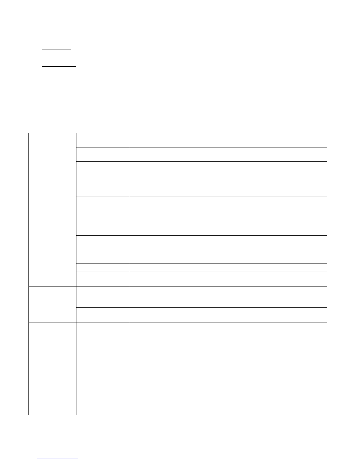
4 TROUBLESHOOTING
Symptom
Probable
Cause
Suggested Remedy
Machine does
not start
Power Supply
Check these areas: Circuit breakers, Voltage, Power leads, Power
connections. Is front display LED lit?
“START” button
Check for green start button light on Input/Output PCB #6 when button is
pressed. If no light, check membrane switch assembly and ribbon cable.
Door Switch
Check for continuity through door switches when door is closed and
locked. Check Input/Output PCB for green door closed light #4 and green
door locked light #3 showing that door switches are functioning correctly.
If no continuity or green light on when door closed and start button
pressed, check door switch and wiring assembly.
Control Breaker
or Fuse
Check 1.5 amp (T-950, T-1200, T-1450 use 2.5amp) breaker or fuse for
continuity. If no continuity, replace breaker or fuse.
Control
Transformer
Check voltage output from control transformer for 120VAC. If voltage is
incorrect, replace transformer.
Check PCB board
Check all wire connections for sure contacts.
CPU board
Single red light should be illuminated. If light is flashing or not on, remove
power from washer for 2 minutes to reset board. Reapply power to
washer and check red light. If on solid, all okay. If still flashing or not on,
replace CPU board.
Check Relay PCB
Check all wire connections for sure contact.
Check Door Lock
Mechanism
Check that 120VAC power is at mechanism after start button is pressed.
Machine
starts then
stops
Door switch
assembly
I/O PCB must have green input lights: DOOR LOCK #3, DOOR CLOSED
#4, TUB EMPTY #14, RUN KEY #1. START #1 will be on when pressed. If
these are not on, check door switches and wiring to/from control panel.
Door locking
mechanism
Check if I/O PCB red output light DOOR SOL. #3 is on. Check that 120VAC
power is at mechanism. Is the linkage rod adjusted properly?
Door does not
lock
CPU Board,
Ribbon Cable or
Input/Output
Board
Check Input/Output PCB for green input door closed light #4 and green
input door locked light. DOOR SOL. #3 light should be illuminated. If light
is flashing or not on, remove power from washer for 2 minutes to reset
CPU. Reapply power to washer and check red CPU light. If on solid, CPU is
okay. If still flashing or not on, replace CPU board. If CPU tests okay,
change Ribbon Cables between CPU and Input/Output PCB. (Check with
Dexter Support for latest testing procedures for I/O PCB.) If no voltage,
replace I/O PCB.
Door lock motor
Check to ensure that door lock motor is receiving 120VAC from
Input/Output PCB. Is I/O PCB red output light #3 on? If 120VAC and
output light is lit, replace door lock motor.
Door Switch
Check for continuity through door latch switch when door closed. If no
continuity, adjust or replace door switch.
CAUTION: Label all wires prior to disconnection when servicing controls. Wiring errors can cause
improper and dangerous operation. Verify proper operation after servicing.
ATTENTION: Lors des opérations d'entretien des commandes, étiqueter tous les fils avant de les déconnecter.
Toute erreur de câblage peut être une source de danger et de panne.
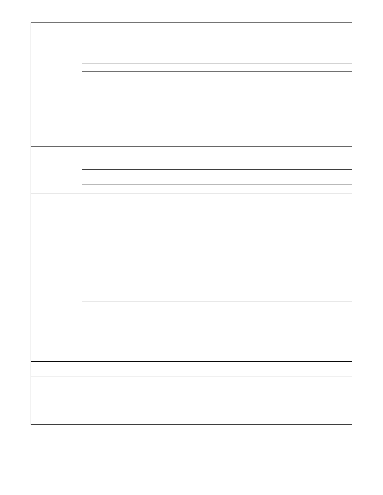
If any of the following symptoms occur on this washer, check the suggested remedies listed below. If all
probable causes have been eliminated and the symptom still exists, contact your local Dexter agent for
further troubleshooting assistance. See contact information at the end of this manual. Parts & Service
Manuals from Dexter are also available for further troubleshooting assistance.
8514-244-001 REV PR page 34
Page 35
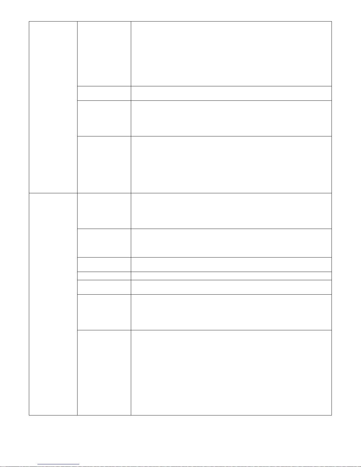
Door will not
open
Thermoactuator
Check to see if thermoactuator(s) and/or its mechanism are stuck or
binding and not allowing the door lock motor to open. Check to be sure
that red light on Input/Output PCB for locking thermoactuator is not
illuminated and that Input/Output PCB is not sending 120VAC power to
the locking thermoactuator during the last 70 seconds of the cycle. Check
to be sure that red light on Input/Output PCB for unlocking
thermoactuator #1 is illuminated and that Input/Output PCB is sending
120VAC to the unlocking thermoactuator during the last 30 seconds of the
cycle.
Door Rod
Check to see that door rod from mechanism to lock assembly is long
enough to allow lock assembly to disengage. If not, adjust rod.
Door locking
mechanism
Check that door lock mechanism is not stuck closed. Check to be sure that
Input/Output PCB is not sending 120VAC power to door locking motor. Be
sure that red light on Input/Output PCB for DOOR SOL #3 is not
illuminated. If door lock motor is receiving 120VAC, check CPU, Ribbon
Cable and Input/Output PCB above.
CPU Board,
Ribbon Cable or
Input/Output
Board
Check red DOOR SOL #3 light on input/output board. If illuminated,
remove power to washer for 2 minutes to reset CPU board. Reapply
power to washer and check red DOOR SOL #3 light. If no light, okay. If
red light is still on, check the CPU board as described above under “Door
does not lock”. If CPU tests okay, change Ribbon Cables between CPU and
input/output board. If red door DOOR SOL #3 light on input/output board
is illuminated, check that 120VAC is going from the input/output board to
the door locking solenoid. If no voltage, replace I/O PCB.
Machine
starts but will
not advance
in the cycle
Water valves
Check to ensure that water valves are operating. If not, check to be sure
that red light on Input/Output PCB for water valves is illuminated (#5, #6,
#7, #8) and that input/output board is sending 120VAC to the water
valve. If 120VAC, change water valve. If no voltage, check Input/Output
PCB.
Drain valve
Check to ensure that drain valve is closing. If not, check for 120VAC to
drain valve from Input/Output PCB red light #4. If 120VAC, change or
clean drain valve. If no voltage, check CPU board, ribbon cable and I/O
PCB.
Fill hose or Water
valve screens
Check all screens for obstructions and clean.
Water
Check to ensure that water is turned on and operating.
Pressure Switch
Hose
Check hose for holes. Be sure the inlet end of the large part of the hose is
lower than the rest of the hose and is free of debris.
Pressure switch
Pressure switch must be in the low or high position to close the circuit to
the input/output board. Either the green low level or high level light on
the input/output board must be lighted. Check pressure switch continuity
between terminals #31 & #22 for low level and #31 and #32 for high
level.
CPU Board,
Ribbon Cable, or
input/output
board
Check if Input/Output PCB for red output LEDs will not light for water
valve and drain valve (#4,5,6,7,8). If no output lights illuminated, check
single red light on CPU board. Single red light should be illuminated. If
light is flashing or not on, remove power from washer for 2 minutes to
reset board. Reapply power to washer and check red CPU light. If on
solid, CPU okay. If still flashing or not on, replace CPU board. If CPU tests
okay, change Ribbon Cables between CPU and input/output board. Check
GREEN input LED #14 tub empty has lit in a drain mode of formula. Make
sure Green input LEDs #13 or #14 are lit if Fill portion of formula is being
called for. If red drain valve or water valve output light on Input/Output
PCB is lit, check to ensure that 120VAC is going from the Input/Output
PCB to the drain valve or water valve. If no voltage, replace I/O PCB.
8514-244-001 REV PR page 35
Page 36
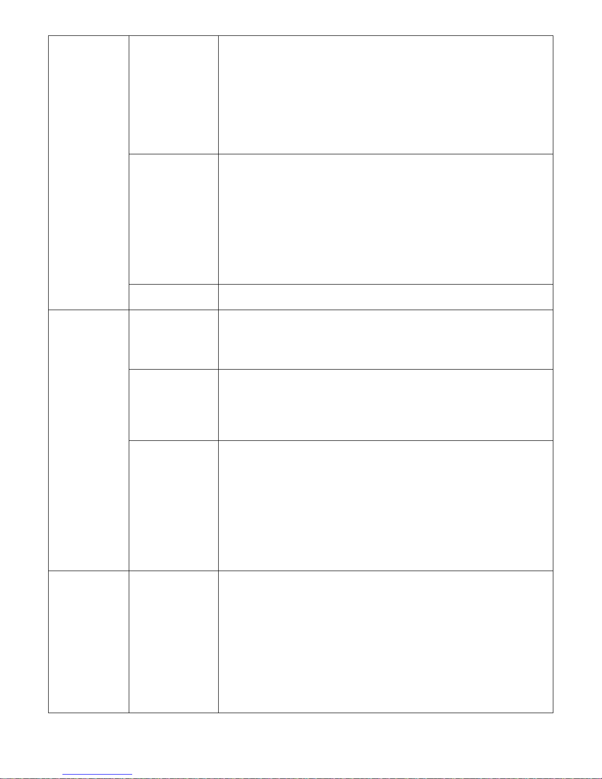
Machine
starts and
advances
through
cycle, but
motor does
not operate
Variable
Frequency Drive
and Motor
Check small green, blue, orange, black, white, red wires (shielded cable)
from the VFD to ensure a good connection at each termination point at
drive or at relays and including all molex connectors.
1. Disconnect power to washer for 2 minutes to reset motor drive.
2. Check incoming power to washer for correct voltage. Line voltage out
of the specified operating range will cause the drive to fault, lighting the
red light.
3. Check motor. Disconnect from power. Disconnect the three wires that
operate the motor from terminals T-1, T-2, T-3 in the drive. Reconnect
power to the washer.
CPU board,
Ribbon Cable
Input/Output
PCB
Check Input/Output PCB for illuminated red motor output lights. If no red
output lights illuminated, check single red light on CPU board. Single red
light should be illuminated. If light is flashing or not on, remove power
from washer for 2 minutes to reset board.
Reapply power to washer and check red CPU light. If on solid, CPU okay.
If still flashing or not on, replace CPU board. If CPU tests okay, change
Ribbon Cables between CPU and Input/Output PCB. (Check with factory
for latest testing procedures for I/O PCB.) If red motor output lights on
Input/Output PCB are illuminated, check to ensure that 0VDC is going
from the input/output board to the variable frequency drive. If no voltage,
replace I/O PCB.
Run Relay
Check to see if there is 12VDC to relay coil. If not, check I/O PCB for
12VDC output. Check if 0VDC through contacts (white wire) to I/O PCB.
Machine
washes but
does not give
intermediate
spin
Pressure Switch
Pressure switch must be in the empty position to does not give close the
circuit to the Input/0utput PCB. The intermediate spin green input tub
empty light #14 on the Input/Output PCB must be lighted. Check pressure
switch for continuity across terminals indicating pressure switch has reset
to empty.
Variable
Frequency Drive
Check Variable Frequency Drive. Check all wires on drive to ensure a good
connection. Check LED display at VFD before powering down
1) Disconnect power to washer for 2 minutes to reset motor drive.
Reconnect to power and check for LED display on VFD.
2) Check incoming power to washer for correct voltage. Line voltage
out of the specified operating range will cause the drive to fault.
CPU board,
Ribbon Cable
Input/Output PCB
Check Input/Output PCB for illuminated red output light for intermediate
spin #15 and #14 for reverse. If no red output light illuminated, check
single red light on CPU board. Single red light should be illuminated. If
light is flashing or not on, remove power from washer for 2 minutes to
reset board. Reapply power to washer and check red CPU light. If on
solid, CPU okay. If still flashing or not on, replace CPU board. If CPU tests
okay, change Ribbon Cables between CPU and Input/Output PCB. (Check
with factory for latest testing procedures for I/O PCB) If red intermediate
spin output light # 15 on the Input/Output PCB is illuminated, check to
ensure that 0VDC is going from the Input/Output PCB to the variable
frequency drive. If no voltage, replace I/O PCB.
Intermediate
speed #1
works, but no
high speed
#2
Variable
Frequency Drive
and Motor
Check small green, black, white wires (shielded cable) from the VFD to
ensure a good connection at each termination point at drive or at relays
and including all molex connectors. Check that green hi speed wire at
drive terminal is giving a 0VDC reading between white and green and
assure that signal is getting to drive.
1. Disconnect power to washer for 2 minutes to reset motor drive.
2. Reconnect to power and check for run light. Run--okay.
3. Check incoming power to washer for correct voltage. Line voltage out
of the specified operating range will cause the drive to fault.
4. Check motor. Disconnect from power. Disconnect the three gray wires
that operate the motor from terminals T-1, T-2, and T-3 in the drive.
5. Reconnect power to the washer.
8514-244-001 REV PR page 36
Page 37
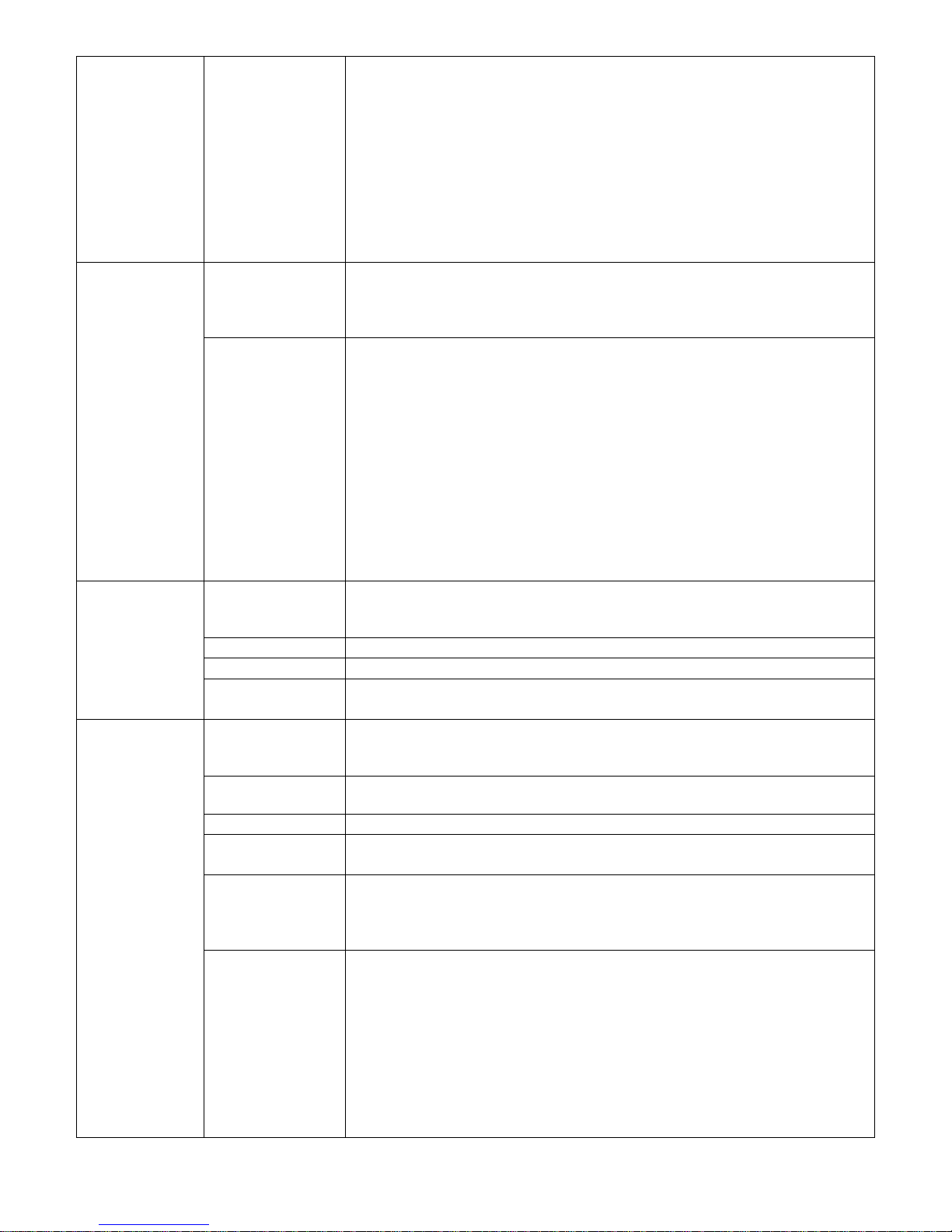
Intermediate
speed #1
works, but no
high speed
#2
(continued)
CPU board,
Ribbon Cable
Input/Output
PCB
Check input/output PCB for illuminated red speed 1 #15 and high speed 2
#16 output lights. If no red output lights illuminated, check single red light
on CPU. Single red light should be illuminated. If light is flashing or not
on, remove power from washer for 2 minutes to reset board. Reapply
power to washer and check red CPU light. If on solid, CPU okay. If still
flashing or not on, replace CPU. If CPU tests okay, change Ribbon Cables
between CPU and input/output PCB. (Check with factory for latest testing
procedures for I/O PCB.) If red intermediate and high extract output lights
on input/output board are illuminated, check to ensure that 0VDC is going
from the Input/Output PCB to the variable frequency drive. If no voltage,
replace I/O PCB.
Machine
tumbles in
only one
direction
Variable
Frequency Drive
Check blue and orange wires on variable frequency drive for alternating
0V to 24 VDC for forward and reverse direction from the Input/Output
PCB. If no voltage, see CPU board, Ribbon Cable or Input/Output PCB
below. Be sure to check wire connections at drive.
CPU Board,
Ribbon Cable, or
input/output
board
Check Input/Output PCB for alternating or Input/Output PCB red output
lights for forward #13 and reverse #14. If no red output lights
illuminated, check single red light on CPU board. Single red light should be
illuminated. If light is flashing or not on, remove power from washer for 2
minutes to reset board. Reapply power to washer and check red CPU light.
If on solid, CPU okay. If still flashing or not on, replace CPU board. If CPU
tests okay, change Ribbon Cables between CPU and Input/Output PCB. If
red forward #13 and reverse #14 output lights on the Input/Output PCB
are illuminated, check to ensure that 0VDC is going from the Input/Output
PCB to the variable frequency drive (only when the lights are on). When
lights are off, check to ensure that 24VDC is going from the Input/Output
PCB to the variable frequency drive. If neither voltage is correct, replace
I/O PCB.
Excessive
vibration
Mounting System
Check these areas:
• Strength of mounting structure, concrete or base.
• Mounting bolts may be loose and need tightening.
Drive Belt
Worn drive belt can cause vibration and noise.
Pulleys
Check for damaged pulleys.
Under loading
Wash recommended load size as specified for washer model (in lb/kg).
Small loads contribute to out of balance loading and increase vibration.
Hot or Cold
water does
not enter the
tub
Water Valves
Check to ensure that water valve is operating. If not, check for 120VAC to
water valve from Input/Output PCB. If 120VAC, change water valve. If no
voltage, check Input/Output PCB as described below.
Fill Hose or Water
Valve screens
Check water inlet screens for blockage and clean if necessary.
Water
Check to ensure that water is turned on and operating.
Pressure Switch
Hose
Check hose for holes. Be sure the inlet end of the large part of the hose is
lower than the rest of the hose and is free of debris.
Pressure Switch
Pressure switch must be in the empty position to close the circuit to the
Input/Output PCB. The green Empty light #14 on the Input/Output PCB
must be lighted. Check pressure switch for continuity across terminals #31
& #22 indicating pressure switch has reset to empty.
CPU board,
Ribbon Cable
Input/Output PCB
Check Input/Output PCB for illuminated red water or Input/Output PCB
valve output light. If no red output light #5 (for Hot) or #7 (for Cold)
illuminated, check single red light on CPU board. Single red light should be
illuminated. If light is flashing or not on, remove power from washer for 2
minutes to reset board. Reapply power to washer and check red CPU light.
If on solid, CPU okay. If still flashing or not on, replace CPU board. If CPU
tests okay, change Ribbon Cables between CPU and Input/Output PCB. If
red water valve output light #5 (for Hot) or #7 (for Cold) on input/output
PCB is illuminated, check to ensure that 120VAC is going from the
Input/Output PCB to the water valve. If no voltage, replace I/O PCB.
8514-244-001 REV PR page 37
Page 38
No hot water
in detergent
dispenser
Water valves
Check to ensure that water valve is operating. If not, check for 120VAC to
water valve from Input/Output PCB. If 120VAC, change water valve. If no
voltage check Input/Output PCB.
Fill hose or Water
valve screens
Check water inlet screens for blockage and clean screens if necessary.
Water
Check to ensure that water is turned on and operating.
CPU board,
Ribbon Cable
Input/Output
PCB
Check Input/Output PCB for illuminated red or Input/Output PCB water
valve output light. If red output light #8 is not illuminated, check single
red light on CPU board. Single red light should be illuminated. If light is
flashing or not on, remove power from washer for 2 minutes to reset
board. Reapply power to washer and check red CPU light. If on solid, CPU
okay. If still flashing or not on, replace CPU board. If CPU tests okay,
change Ribbon Cables between CPU and Input/Output PCB. If red water
valve output light #8 on input/output PCB is illuminated, check to ensure
that 120VAC is going from the Input/Output PCB to the water valve. If no
voltage, replace I/O PCB.
Water does
not flush
softener
compartment
Water Valves
Check to ensure that water valve is operating. If not, check for 120VAC to
water valve from Input/Output PCB. If 120VAC, change water valve. If no
voltage check Input/Output PCB.
Fill hose or Water
valve screens
Check all screens for obstructions and clean.
Water
Check to ensure that water is turned on and operating.
Water comes
in but level
does not rise
Drain Valve
Check these areas:
• Drain valve blockage
• Drain valve motor and gear train. If power but drain valve does not
close, replace valve.
• Power to the drain valve. If no power to drain valve, check
(brown/yellow) circuit for power.
Water Valves
Check or replace water valve diaphragms.
Water level
too high
Pressure Switch
Pressure switch must be in the low or high position to close the circuit to
the Input/Output PCB. Either the green low level #13 or high level light
#15 on the Input/Output PCB must be lighted. Check pressure switch
continuity between terminals #31 & #22 for low level and #31 and #32
for high level.
Pressure Switch
Hose
Check hose for holes. Be sure the inlet end of the large part of the hose is
lower than the rest of the hose and is free of debris.
CPU board,
Ribbon Cable
Input/Output PCB
Check Input/Output PCB for illuminated green low #13 or high level input
light #15. If green input light is illuminated, check single red light on CPU
board. Single red light should be illuminated. If light is flashing or not on,
remove power from washer for 2 minutes to reset board. Reapply power
to washer and check red CPU light. If on solid, CPU okay. If still flashing or
not on, replace CPU board. If CPU tests okay, change Ribbon Cables
between CPU and Input/Output PCB. (Check with factory for latest testing
procedures for I/O PCB.) If still not corrected, change Input/Output PCB.
Water drains
slowly
Drain System
Check hoses and drain valve for blockage. Clean if necessary. Check
building drains for blockage or inadequate size.
Water
leakage
around
loading door
Door Adjustment
Door may need adjustment due to abuse or wear. Check tightness around
perimeter using a dollar bill. Adjust left to right tightness by shims at door
lock or hinge side. It is important to center gasket to tub opening before
tightening door to hinge bolts. Chalk may be used on tub front to show
point of contact with tub. If gasket is deformed, worn, or damaged,
replace.
8514-244-001 REV PR page 38
Page 39

IMPORTANT
TRANSIENT VOLTAGE SURGE SUPPRESSORS
Like most electrical equipment your new machine can be damaged or have its life
shortened by voltage surges due to lightning strikes which are not covered by factory
warranty. Local power distribution problems also can be detrimental to the life of
electrical components. We recommend the installation of transient voltage surge
suppressors for your new equipment. These devices may be placed at the power
supply panel for the complete installation and don’t require an individual device for each
machine.
These surge protectors help to protect equipment from large spikes and also from small
ongoing spikes in the power that occur on a day to day basis. These smaller surges can
shorten overall life of electrical components of all types and cause their failure at a later
date. Although they can’t protect against all events, these protective devices have a
good reputation for significantly lengthening the useful life of electronic components.
Electronic components are helped to have a longer useful life when they are supplied
with the clean stable electrical power they like.
We are including the following names and phone numbers of a few suppliers of these
devices for those who don’t currently have a source.
MANUFACTURER CONTACT PHONE
Innovative Technology, Inc Distributor 1-800-809-2772 or
(Part of Eaton Corporation) www.itvss.com
EFI Electronics Corporation Factory 1-800-877-1174
(Part of Schneider Electric)
MCG Surge Protection Factory 1-800-851-1508 or
www.mcgsurge.com
Advanced Protection Factory 1-800-237-4567 or
Technologies Inc. www.aptsurge.com
8514-244-001 REV PR page 39
Page 40

5 SERVICE AND PARTS
The following parts are provided with each machine for use in installation.
Dexter Part Number Description Quantity (T-900/T-950)
9990-027-013 Hose, Water Supply 2 or 4
8641-242-000 Washer, Inlet Hose 2 or 4
9565-003-001 Strainer, Inlet Hose 4 or 8
Contact distributor or Dexter Laundry, Inc. if a steel-mounting base is required.
For service and parts information, contact your local Dexter agent. To find your
local Dexter agent, use the Distributor Locator at the website shown below. If a
Dexter agent is not available, contact Dexter Laundry, Inc. directly as listed
below:
Mailing Address: 2211 West Grimes Avenue Phone: 1-800-524-2954
Fairfield, IA 52556
USA
Website: www.dexter.com
8514-244-001 REV PR page 40
 Loading...