

Dexter Laundry T-400 On-Premise, T-350 SWD, T-450 SWD, T-750 SWD, T-300 Operator's Manual
...
INDUSTRIAL WASHER
MODEL T-400 ON-PREMISE
V-SERIES CONTROL
OPERATOR’S MANUAL
INSTALLATION & OPERATION
INSTRUCTIONS
Please read this information and retain for reference.
WARNING - THIS WASHER IS EQUIPPED WITH DEVICES AND FEATURES RELATING TO ITS SAFE
OPERATION. TO AVOID INJURY OR ELECTRICAL SHOCK, DO NOT PERFORM ANY SERVICING UNLESS
QUALIFIED TO DO SO.
IT IS THE RESPONSIBILITY OF THE OWNER TO CHECK THIS EQUIPMENT ON A FREQUENT
BASIS TO ASSURE ITS SAFE OPERATION.
A machine should NOT be allowed to operate if any of the following occur:
- Excessively high water level.
- If machine is not connected to a properly grounded circuit.
- If the door does not remain securely locked during the entire cycle.
- Vibration or shaking from an inadequate mounting or foundation.
WARNING - SAFETY PRECAUTIONS
- Always shut off power and water supply before servicing.
- Do not overload the washer.
- Do not open door when cylinder is in motion or it contains water.
- Do not bypass any safety devices of this washer.
- Do not use volatile or flammable substances in or near this washer.
- Keep all panels in place. They protect against shock and injury and add rigidity to the washer.
PREVENTIVE MAINTENANCE REQUIREMENTS
DAILY
- Check that the loading door remains securely locked and cannot be opened during an entire
cycle.
- Check the water connections for leaks.
- Clean the top, front, and sides of the cabinet to remove residue.
- Clean the soap dispenser and lid and check that all dispenser mounting screws are in-place and
tight.
- Check the drain valve for leaking and that it opens properly.
- Check the loading door for leaks. Clean the door seal of all foreign matter.
- Leave the loading door open to aerate the washer when not in use.
QUARTERLY
- Make sure the washer is inoperative by switching off the main power supply.
- Check the V-belts for wear and proper tension.
- Clean lint and other foreign matter from around motor.
- Check all water connections for leaks.
- Wipe and clean the inside of the washer and check that all electrical components are free of
moisture and dust.
- Remove and clean water inlet hose filters. Replace if necessary.
- Check anchor bolts. Retighten if necessary
IMPORTANT: Replace any and all panels that were removed to perform daily and/or quarterly
maintenance.
8514-238-001 REV PR page 1

TABLE OF CONTENTS
MODEL
T-400 30 LB. WASHER
CAPACITY
30 LBS/4 CUBIC FT. (13.6 kg/113 L)
CYLINDER SIZE
25” DIA X 14 1/8” DEEP (63.5cm X 36cm)
ELECTRICAL
208-240 VAC, 60 HZ, 1 OR 3 PHASE
DRIVE SYSTEM
SOFT START REVERSING INVERTER DRIVE, 2 HP MOTOR
WASH SPEED
50 RPM
INTERMEDIATE
EXTRACT
411 RPM (60 G’S)
FINAL EXTRACT
531 RPM (100 G’S)
MACHINE CONTROL
PROGRAMMABLE COMPUTER UP TO 6 CYCLES
WATER INLET
2 SOLENOID OPERATED VALVES
FLOW RATE: 9 GAL/MIN (34 L/MIN) EACH, 30-120 PSI
DRAIN VALVE
3” (76 mm) DIAMETER
1 INSTALLATION INSTRUCTIONS .......................................................................... 3
1.1 FOUNDATION REQUIREMENTS ...................................................................... 3
1.2 MOUNTING .................................................................................................. 3
1.3 PLUMBING ................................................................................................... 7
1.4 DRAIN ......................................................................................................... 7
1.5 PROTECTIVE FILM ........................................................................................ 7
1.6 ELECTRICAL ................................................................................................. 7
1.6.1 INSTALLING THE ELECTRICAL CONNECTION ........................................... 7
1.6.2 FUSING REQUIREMENTS......................................................................... 8
1.6.3 CONTROLS TRANSFORMER (208-240V models only) ................................ 8
1.6.4 MAXIMUM SPIN SPEED ADJUSTMENT ...................................................... 9
1.7 INJECTION SOURCE CONNECTIONS ............................................................ 10
1.8 OPERATION CHECK .................................................................................... 10
2 OPERATING INSTRUCTIONS ............................................................................. 11
2.1 STARTING THE WASHER ............................................................................. 11
2.2 END OF CYCLE ........................................................................................... 12
2.3 SAFETY DOOR LOCK ................................................................................... 12
2.4 VARIABLE FREQUENCY DRIVE INDICATORS ................................................ 12
3 MACHINE PROGRAMMING INSTRUCTIONS ........................................................ 13
3.1 EDITING AN EXISTING CYCLE ..................................................................... 13
3.2 DEFAULT WASHER CYCLE PROGRAMS ......................................................... 15
3.3 RAPID ADVANCE MODE .............................................................................. 19
4 WASHER ERROR CODES ................................................................................... 20
5 TROUBLESHOOTING ........................................................................................ 22
6 SERVICE AND PARTS ........................................................................................ 26
Table 1: Washer Specifications
8514-238-001 REV PR page 2

1 INSTALLATION INSTRUCTIONS
All washers must be installed in accordance with all local, state and national
building, electrical, plumbing and other codes in effect in the area.
WARNING:
THESE INSTALLATION AND SERVICING INSTRUCTIONS ARE FOR USE
BY QUALIFIED PERSONNEL ONLY. TO AVOID INJURY AND ELECTRICAL
SHOCK, DO NOT PERFORM ANY SERVICING OTHER THAN THAT
CONTAINED IN THE OPERATING INSTRUCTIONS, UNLESS QUALIFIED.
1.1 FOUNDATION REQUIREMENTS
This machine is designed for use on or over bare concrete floor - not to be
used above combustible flooring, such as carpet or wood. The washer
must be securely bolted to a substantial concrete floor, or mounted upon
a suitable base that is securely bolted to a substantial concrete floor.
CARE MUST BE TAKEN WITH ALL FOUNDATION WORK TO ENSURE A
STABLE UNIT INSTALLATION, ELIMINATING POSSIBILITIES OF
EXCESSIVE VIBRATION.
All installations require concrete floors 6 inches (150mm) or thicker.
Anchor bolts or expansion anchors must be of a quality grade and a
minimum of 1/2 inch (14 mm) diameter. Mounting hardware is not
provided with the machine.
1.2 MOUNTING
A concrete pedestal or steel-mounting base that elevates the machine
approximately 6 inches (150 mm) above the floor level is recommended to
provide easy access to the loading door. Allow a minimum 24 inches
(600mm) of clearance behind the rear of the machine to provide access
for motor service. Refer to Figures Figure 1-1 and Figure 1-2 for machine
bolt-down dimensions. Contact a Dexter laundry equipment distributor for
recommended steel mounting bases.
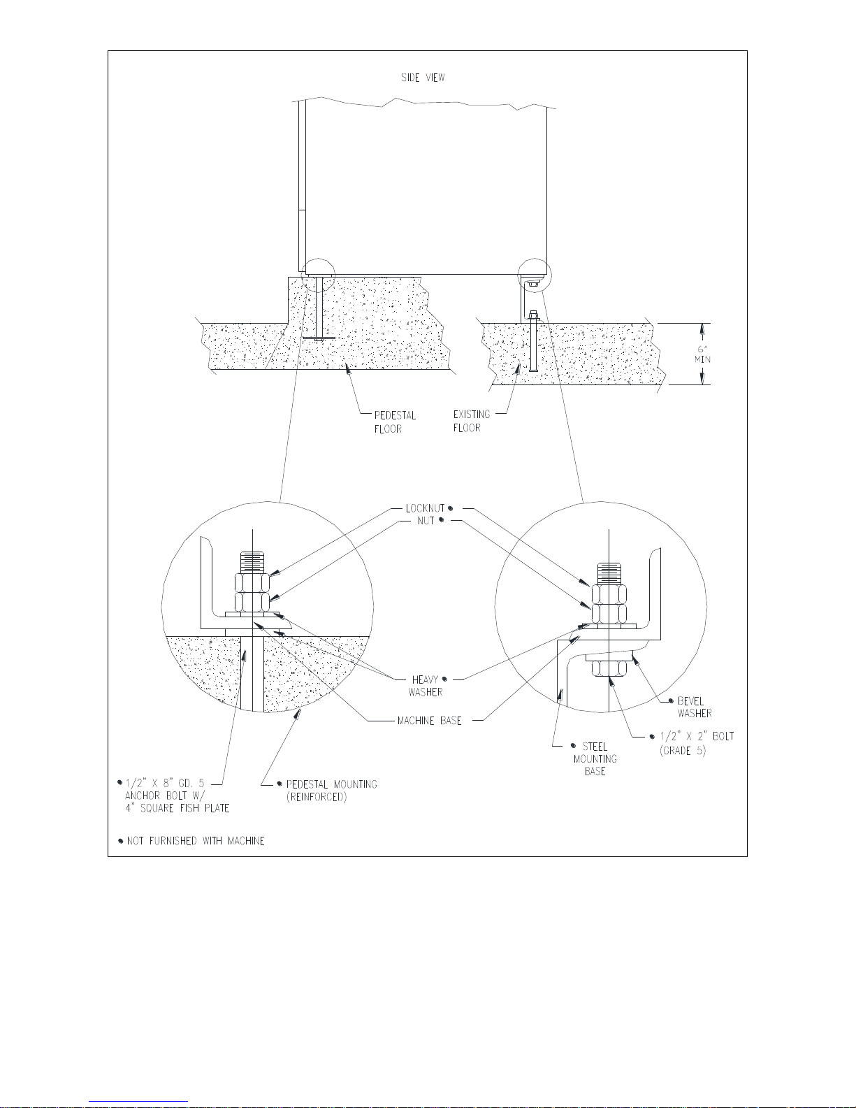
If an elevated concrete pedestal is desired, it should be embedded into
the existing floor. Anchor bolts should be 1/2" x 8" (14 mm x 200 mm),
grade 5 or better, headed by a 4 inch (10 cm) square fish plate and
should protrude 1 7/8” (48 mm) above the finished surface of the
pedestal.
EXPANSION ANCHORS ARE NOT RECOMMENDED FOR USE IN CONCRETE
PEDESTALS BECAUSE THE ANCHORS ARE TOO CLOSE TO AN EDGE,
CAUSING IT TO BREAK OUT.
Refer to Figures Figure 1-1 and Figure 1-3 for recommended concrete
pedestal dimensions. Refer to Figure Figure 1-4 for overall machine
mounting dimensions.
8514-238-001 REV PR page 3
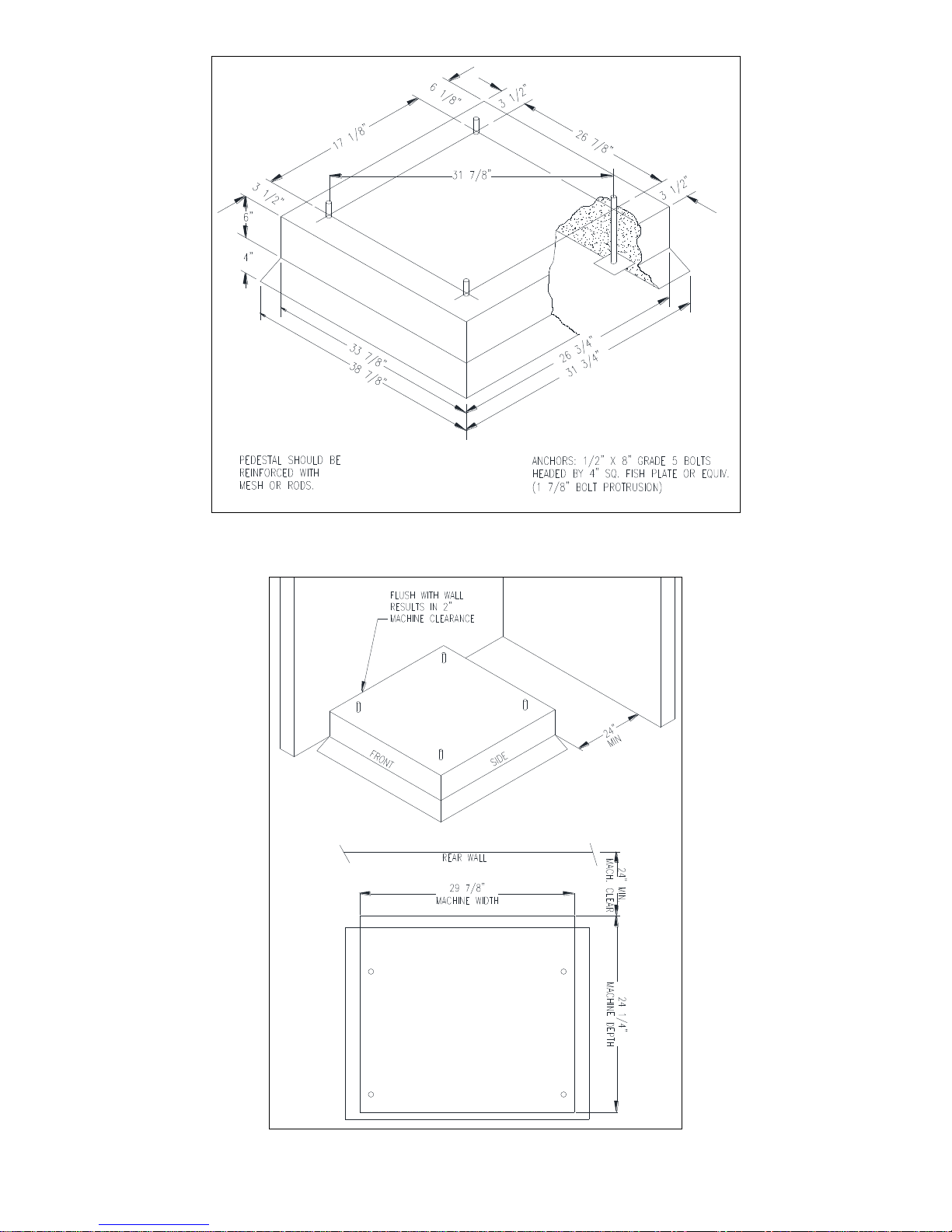
Figure 1-1: Concrete Pedestal Mounting
8514-238-001 REV PR page 4
Figure 1-2: Floor Outline
8514-238-001 REV PR page 5
Figure 1-3: Machine Mounting Detail
8514-238-001 REV PR page 6
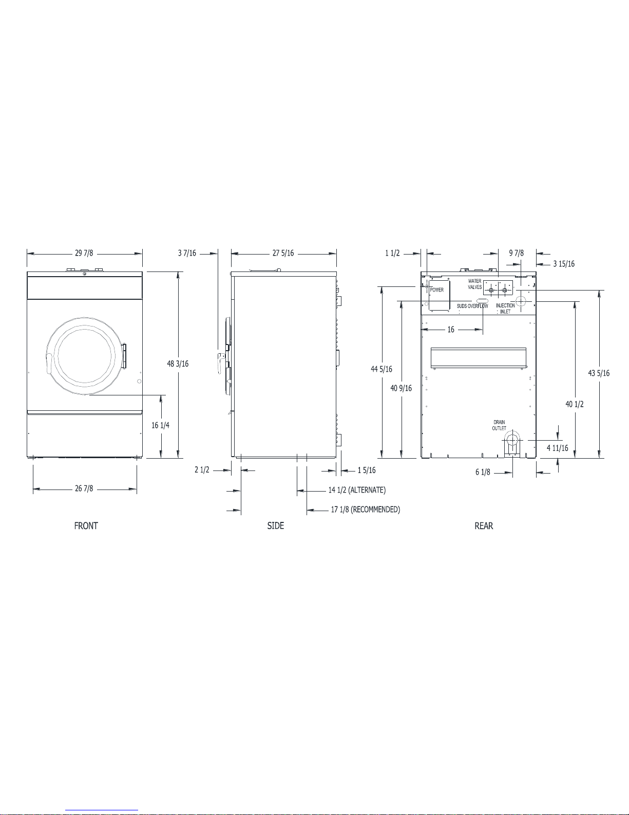
Figure 1-4: T-400 Industrial Washer Mounting Diagram

1.3 PLUMBING
Two 48 inch (1.22 m) water supply hoses are provided with each machine.
The threaded connections on the hoses are ¾-11 ½ NHT.
Separate hot and cold water lines must be supplied to the machine,
maintaining 30 psi to 120 psi (207 kPa to 827 kPa) water flow pressure. A
140°F (60°C) hot water supply is recommended for best washing results.
Do not exceed 180°F (82°C) water temperature.
1.4 DRAIN
The drain outlet tube at the rear of the machine is 3” (76 mm) in
diameter. Any drain hose used must be lower than the drain valve to
assure proper draining.
1.5 PROTECTIVE FILM
The machine may have protective adhesive film on the front control panel
label area and on the front, top, and side stainless steel panels. The film
may be peeled off before putting the machine into service.
1.6 ELECTRICAL
The Dexter T-400 single/three-phase 208-240VAC 60 Hz washing
machines are intended to be permanently installed appliances. No power
cord is provided. The machine should be connected to an individual
branch circuit not shared by lighting or other equipment. The connection
should be sheathed in liquid tight flexible conduit, or equivalent, with
conductors of the proper size and insulation. A qualified technician should
make such connections in accordance with the wiring diagram with a
minimum 12 gauge wire.
WARNING:
SHUT OFF POWER AND WATER BEFORE OPENING ANY SERVICE
PANELS.
1.6.1 INSTALLING THE ELECTRICAL CONNECTION
1.6.1.1 Disconnect all power to the washer.
1.6.1.2 Remove the top panel of the washer and locate the
power terminal block near the back of the control
compartment.
1.6.1.3 If power is 208-240-3PH-60Hz, connect L1, L2, L3
1.6.1.4 If power is 208-240-1PH-60Hz, connect L1, L2 and
NOTE: It is important that the grounding screw next to the power
terminal block TB-1 be connected to a good external ground.
8514-238-001 REV PR page 7
and Ground. If there is a high leg, it must be
connected to L3.
Ground.
1.6.2 FUSING REQUIREMENTS
Single- and Three -phase 208-240VAC models:
15 AMP TIME-DELAY (DUAL ELEMENT) FUSE (or equivalent circuit
breaker)
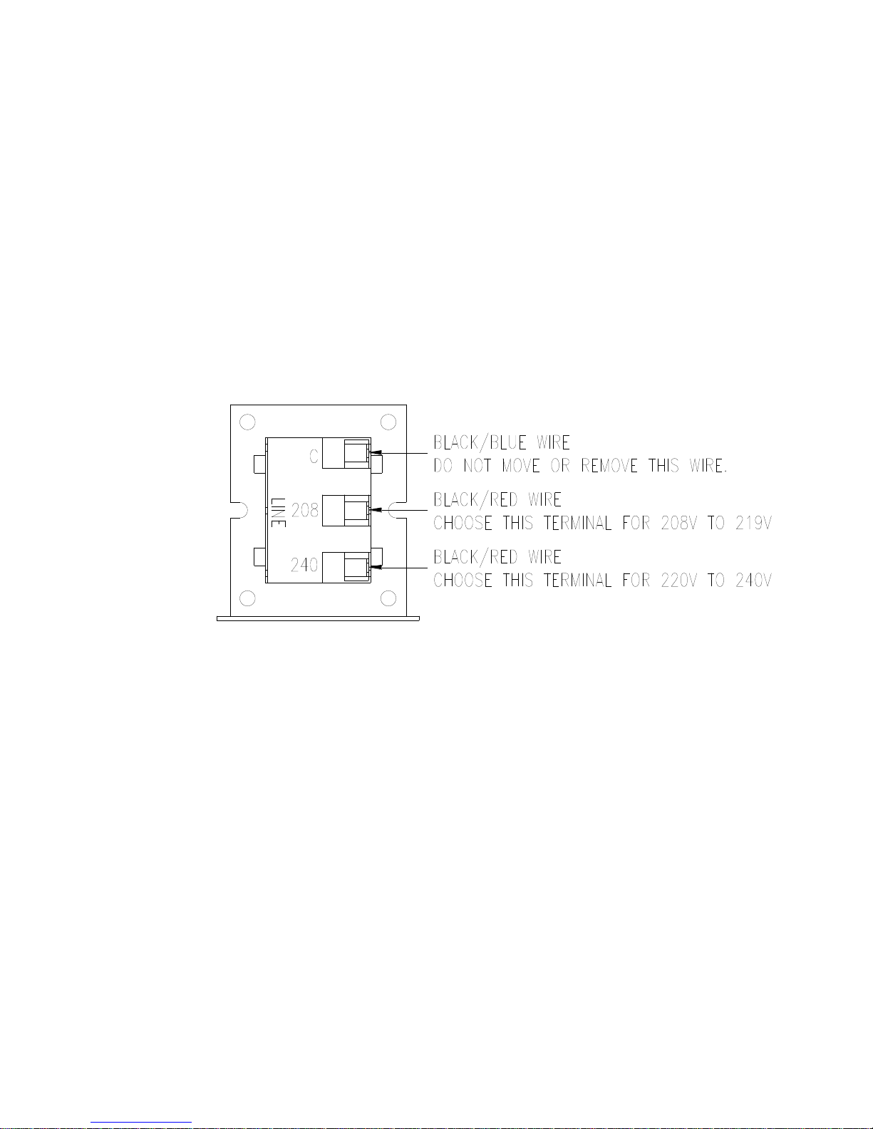
1.6.3 CONTROLS TRANSFORMER (208-240V models only)
The controls transformer is located inside the control trough and
steps a range of 208 to 240 volts down to 115 volts. There are two
terminals on the controls transformer for the primary (incoming)
power. Use the terminal marked “208V” for power supplies
between 208 and 219 volts. Use the terminal marked “240V” for
power supplies between 220 and 240 volts. Refer to Figure 1-5 for
control transformer connections.
Figure 1-5: Control Transformer Connections
8514-238-001 REV PR page 8
 Loading...