

Dexter Laundry HIGH SPEED 25LB WASHER Installation & Operation Instructions

`P/N 8514-064-001 Rev A
HIGH EXTRACT WASHER
25 LB (11.4 KG) CAPACITY
STACKABLE
ON-PREMISE LAUNDRY
COMPUTER CONTROL
THE
DEXTER
COMPANY
OWNER'S BOOKLET
INSTALLATION & OPERATION
INSTRUCTIONS
Please read this information and retain for reference.
WARNING - THIS WASHER IS EQUIPPED WITH DEVICES AND FEATURES RELATING TO ITS SAFE
OPERATION. TO AVOID INJURY OR ELECTRICAL SHOCK, DO NOT PERFORM ANY SERVICING
UNLESS QUALIFIED TO DO SO.
IT IS THE RESPONSIBILITY OF THE OWNER TO CHECK THIS EQUIPMENT ON A FREQUENT
BASIS TO ASSURE ITS SAFE OPERATION.
A machine should not be allowed to operate if any of the following occur:
- Excessively high water level.
- If machine is not connected to a properly grounded circuit.
- If the door does not remain securely locked during the entire cycle.
- Vibration or shaking from an inadequate mounting or foundation.
WARNING - FOR SAFETY
1. Always shut off power and water supply before servicing.
2. Do not overload the washer.
3. Do not open door when cylinder is in motion or it contains water.
4. Do not bypass any safety devices of this washer.
5. Do not use volatile or flammable substances in or near this washer.
6. Keep all panels in place. They protect against shock and injury and add rigidity to the washer.
PREVENTIVE MAINTENANCE REQUIREMENTS
DAILY
- Check that the loading door remains securely locked and cannot be opened during the entire cycle.
- Check the water connections for leaks.
- Clean the top and sides of the cabinet to remove residue.
- Clean the soap dispenser and lid and check that all dispenser mounting screws are in-place and tight.
- Check the drain valve for leaking and that it opens properly.
- Check the loading door for leaks. Clean the door seal of all foreign matter.
- Leave the loading door open to aerate the washer when not in use.
QUARTERLY
- Make sure the washer is inoperative by switching off the main power supply.
- Check the V-belts for wear and proper tension.
- Clean lint and other foreign matter from around motor.
- Check all water connections for leaks.
- Wipe and clean the inside of the washer and check that all electrical components are free of moisture and dust.
- Remove and clean water inlet hose filters. Replace if necessary.
- Check anchor bolts - retighten if necessary
IMPORTANT: Replace any and all panels that were removed to perform daily and/or quarterly maintenance.

25 LB HIGH EXTRACT WASHER
THE
DEXTER
COMPANY
INSTALLATION INSTRUCTIONS
This washer may have been purchased as part of a stacked washer/dryer. In addition to thesr
instructions, please also refer to the installation instructions that accompany the dryer when
installing this product.
All washers must be installed in accordance with all local, state and national building, electrical,
plumbing and other codes in effect in the area.
WARNING - THESE INSTALLATION AND SERVICING INSTRUCTIONS
ARE FOR USE BY QUALIFIED PERSONNEL ONLY. TO AVOID INJURY
AND ELECTRICAL SHOCK DO NOT PERFORM ANY SERVICING
OTHER THAN THAT CONTAINED IN THE OPERATING
INSTRUCTIONS, UNLESS QUALIFIED.
FOUNDATION REQUIREMENTS
WARNING: This machine is designed for use on or over bare concrete floor - not to be used
above combustible flooring. The washer must be securely bolted and grouted to a substantial
concrete floor, or mounted and grouted upon a suitable base, which is in turn, securely bolted
and grouted to a substantial concrete floor. CARE MUST BE STRESSED WITH ALL
FOUNDATION WORK TO INSURE A STABLE UNIT INSTALLATION, ELIMINATING
POSSIBILITIES OF EXCESSIVE VIBRATION. All installations must be made on sound
concrete floors, 6 inches (152 mm) or thicker. Anchor bolts or expansion anchors must be of a
quality grade and a minimum of 5/8-inch (16 mm) diameter.
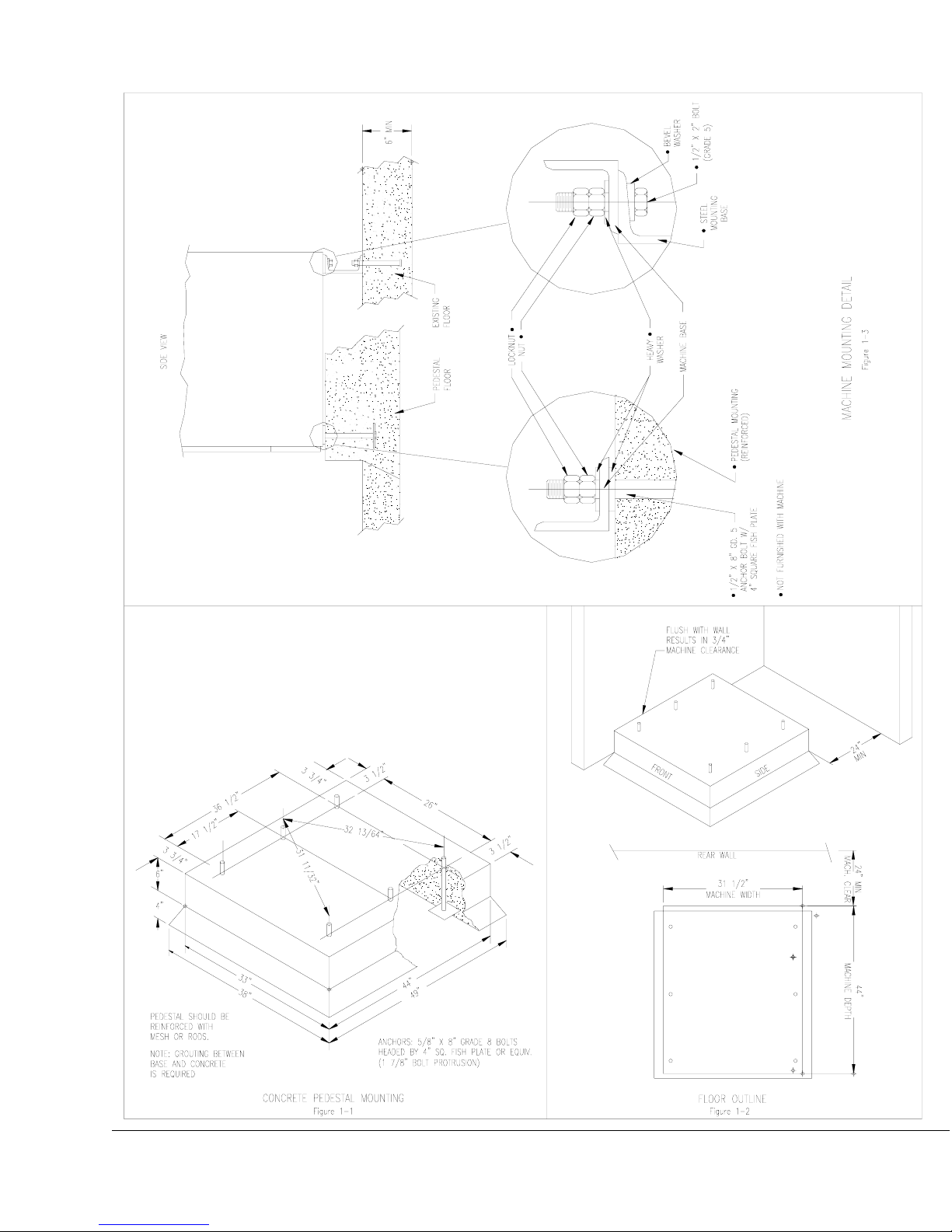
MOUNTING
A concrete pedestal or steel-mounting base that elevates the machine approximately 6 inches
(152 mm) above the floor level is recommended to provide easy access to the loading door.
Allow a minimum of 24 inches (610mm) of clearance behind the rear of the machine, to provide
access for motor removal. Refer to Fig. 1-1 and 1-2 for machine bolt-down dimensions.
If an elevated concrete pedestal is desired, it should be embedded into the existing floor. Anchor
bolts should be 5/8" x 8" (16 mm x 200 mm), grade 8 or better, headed by a 4 inch (10 cm)
square fish plate and should protrude 1 7/8 inches (48 mm) above the finished surface of the
pedestal. EXPANSION ANCHORS ARE NOT RECOMMENDED FOR USE IN CONCRETE
PEDESTALS, BECAUSE THE ANCHORS ARE TOO CLOSE TO AN EDGE, CAUSING IT
TO BREAK OUT. (See Fig. 1-1 and 1-3.)

PLUMBING
Water supply hoses are furnished with each machine. Separate hot and cold water lines must be
provided, maintaining 30 P.S.I . (207 kPa) to 120 P.S.I. (818 kPa) water flow pressure. A 140F
(60C) degree hot water supply is recommended for best washing results.
DRAIN
The drain outlet tube at the rear of the machine is 3 inches (76 mm) in diameter. A flexible hose
material (Pt. #9242-417-003) is available to extend this draining system. Any drain hose used must
be lower than the drain valve to assure proper draining.
ELECTRICAL 208-240V/1PH/60HZ OR 208-240/3PH/60HZ
WARNING
SHUT OFF POWER AND WATER BEFORE OPENING ANY SERVICE PANELS.
This Dexter washing machine is intended to be a permanently installed appliance. No power cord is
provided. The machine should be connected to an individual branch circuit not shared by lighting or
other equipment. Where required, a means for disconnection with a contact separation distance of at
least 3mm must be provided. The connection should be sheathed in liquid-tight flexible conduit, or
equivalent, with conductors of the proper size and insulation.
TO MAKE ELECTRICAL CONNECTIONS: Disconnect all power to the washer. Remove screw and
lift out the cover located in the upper left corner of the machine (as viewed from the back).
If power is 208-240-3PH-60Hz, connect L1, L2, L3 and ground. If there is a high leg it must be
connected to L3.
If power is 208-240-1PH-60Hz, connect L1, L2 and Ground.
NOTE: It is important that the grounding screw next to the power terminal block TB-1 be
connected to a good external ground.
FUSING REQUIREMENTS
:
SINGLE- or THREE -PHASE POWER - 20 AMP TIME-DELAY (DUAL ELEMENT) FUSE
(or equivalent circuit breaker)
CONTROLS TRANSFORMER
The controls transformer is mounted at the back of the control trough and has two voltage range
settings. One terminal is provided for the range of 208 to 220 volts and the other is for the range of
221 to 240 volts. Make sure the transformer is wired to match the intended supply voltage.
INJECTION SOURCE DETAILS

The washer control may be programmed to send 120V output signals for a chemical injection
system. The signals are not intended as a power source and must be limited to less than 100
milliamps of current. There is a separate terminal block for connection of the external injection
signals. For the injection sources, program codes 0 through 6 are as shown in the table below.
Dexter
Recommended
Connections
Detergent
Bleach
Starch
Sour/Softener
Controller
Programmed
Signals
1
2
3
4
5
6
0
Injection
Terminal Block
Circuits
A
B
C
D
A and B
C and D
None
CHECKOUT
After all mounting, plumbing and electrical work is completed, the washer should be run through a
cycle and checked for water leaks and proper functioning.
 Loading...