

Page 1
WARNING: For your safety the
information in this manual must be
followed to minimize the risk of fire
or explosion or to prevent property
damage, personal injury or loss of
life.
Ne pas entreposer ni utiliser d'essence ni d'autres
vapeurs ou liquides inflammables dans le voisinage
de cet appareil ou de tout autre appareil.
– QUE FAIRE SI VOUS SENTEZ UNE ODEUR DE
GAZ:
• Ne pas tenter d'allumer d'appareil.
• Ne touchez à aucun interrupteur. Ne pas
vous servir des téléphones se trouvant
dans le bâtiment où vous vous trouvez.
• Évacuez la pièce, le bâtiment ou la zone.
• Appelez immédiatement votre
fournisseour de gaz depuis un voisin.
Suivez les instructions du fournisseur.
• Si vous ne pouvez rejoindre le fournisseur
de gaz, appelez le service des incendies.
– L'installation et l'entretien doivent être assurés par
un installateur ou un service d'entretien qualifié
POUR VOTRE SÉCURITÉ
Ne pas enteposer ni utiliser d'essence ni d'autres
vapeurs ou liquides inflammables dans le voisinage
de cet appareil ou de tout autre appareil.
You, the purchaser, must post in a prominent location instructions to be followed in the event the user
smells gas. Consult your local gas supplier for
procedure to be followed if the odor of gas is
present.
AVERTISSEMENT. Assurez-vouz
de bien suivre les instructions
données dans cette notice pour
réduire au minimum le risque
d'incendie ou d'explosion ou pour
éviter tout dommage matérial,
toute blessure ou la mort.
COMMERCIAL DRYER
Do not store or use gasoline or other flammable
vapors and liquids in the vicinity of this or any
other appliance.
– WHAT TO DO IF YOU SMELL GAS
• Do not try to light any appliance.
• Do not touch any electrical switch; do
not use any phone in your building.
• Clear the room, building or area of all
occupants.
• Immediately call your gas supplier from
a neighbor’s phone. Follow the gas
supplier’s instructions.
• If you cannot reach your gas supplier,
call the fire department.
– Installation and service must be performed by
a qualified installer, service agency or the
gas supplier.
FOR YOUR SAFETY
Do not store or use gasoline or other flammable
vapors or liquids in the vicinity of this or any other
appliance.
MODEL T-30, T-50, T-80 VENDED
C-SERIES CONTROL, NATURAL GAS/LP HEATED
INSTALLATION & OPERATION INSTRUCTIONS
The dryer must not be stored or installed where it will be exposed to water and/or weather.
Post the following “For Your Safety” caution in a
prominent location:
It is important that you read this Manual and retain it
for future reference. For service or replacement parts,
contact the distributor in your area or the
manufacturer.
8514-234-001 rev. A page 1
OPERATOR’S MANUAL
Dexter Laundry, Inc.
2211 W. Grimes
Fairfield, Iowa 52556
Page 2
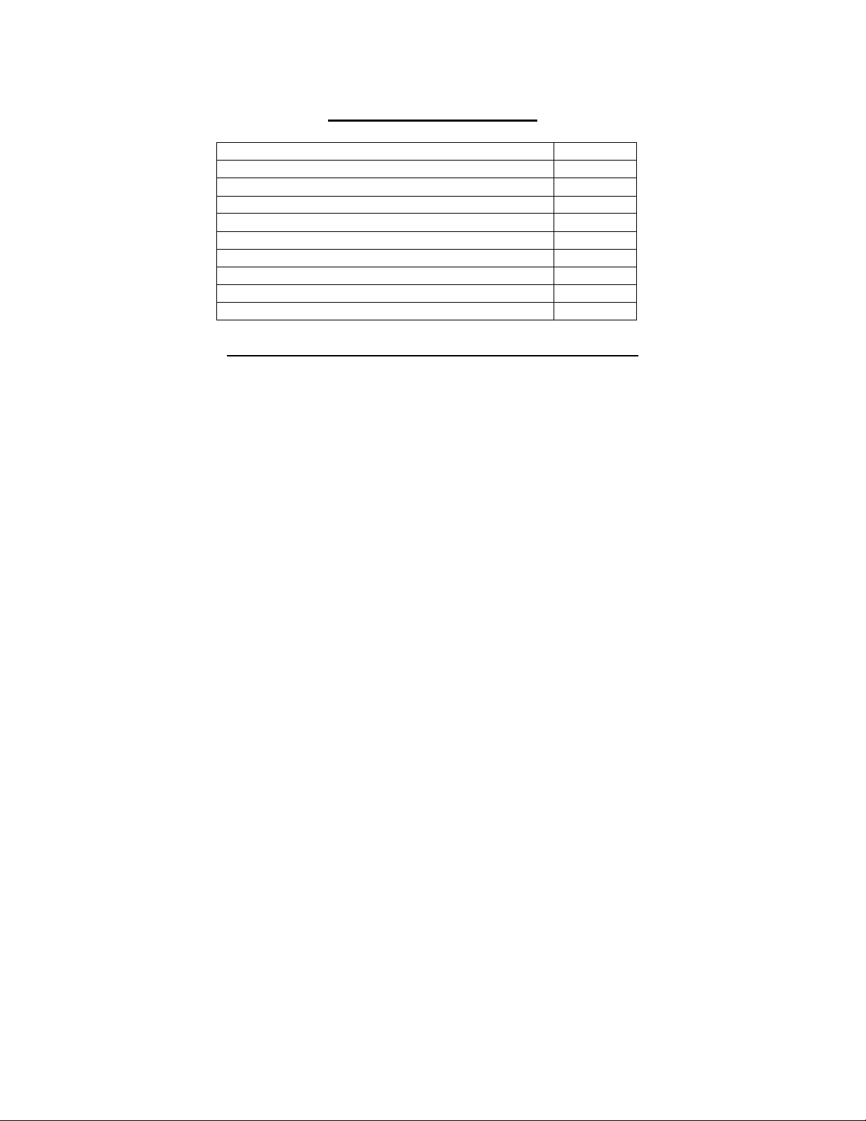
Page No.
Warnings about use and operation
2
Dryer Specifications
3- 5
Dryer Dimensions
6- 8
Installation and Operating Instructions
9- 12
Dryer Shutdown
13
Operating Instructions
13
Programming the Dryer Control
14- 24
Servicing and Troubleshooting
25
Preventative Maintenance Instructions
26- 27
TABLE OF CONTENTS
WARNINGS ABOUT USE AND OPERATION
DO NOT MODIFY THIS APPLIANCE. KEEP SHIELDS, GUARDS, AND COVERS IN PLACE. These
safety devices are provided to protect everyone from injury.
It is ABSOLUTELY ESSENTIAL that the dryer be grounded to a known earth (zero) ground in accordance
with local codes or, in the absence of local codes, with the latest editions of the National Electric Code, ANSI//NFPA
70 or Standard CSA C22.1 Canadian Electrical Code Part 1. This is not only for personal safety, but is necessary
for proper operation of the controller. Failure to do so will void the warranty of the controller.
A DRYER SHOULD BE CONNECTED TO POWER FOR THREE (3) MINUTES before it is operated or
before a program change is made. Operation or program changes, which occur during this "power up" period, are
subject to loss in case of power interruption. After the initial three minutes, all programmed data is protected
from power interruptions of any length and the customer's individual cycle is protected up to 3 seconds. This is
done without batteries.
LEAVE THE ELECTRICAL POWER TO THE DRYER ON AT ALL TIMES except when necessary for service
or other similar activities. The hour meter function adds only full hours to its reading. If the power is shut off every night,
any fraction of an hour of time that is on the machine at that time will be lost. Turning the power off every night
could also have some effect on the long-term life of the memory after a number of years. Turning power off
occasionally won’t affect the unit.
THIS DRYER IS EQUIPPED WITH AN OVER-TEMPERATURE THERMOSTAT located to the right of
the motor on the rear of the cabinet. If the dryer ceases to operate, refer to your “Service Procedure and Parts
Data” book for instructions.
rough handling in shipment, may trip the thermostat. It may be reset by inserting a wooden pencil or dowel
through the bushing in the cover.
DO NOT SPRAY AEROSOLS IN THE VICINITY OF THIS APPLIANCE while in operation.
THIS APPLIANCE SHALL NOT BE USED TO DRY OFF SOLVENTS OR DRY-CLEANING FLUIDS.
CHECK THIS THERMOSTAT WHEN INSTALLING DRYER to assure it is not tripped. Impacts such as
8514-234-001 rev. A page 2
Page 3

SPECIFICATIONS
30 lb. Commercial Dryer: T-30 – DC0030NB-10EC1X (60 Hz), DC0030NB-39AC1X (50 Hz)
Cabinet Height 72 1/4” 1835 mm.
(Assumes minimum leveling leg adjustment)
Cabinet Width 31 1/2” 800 mm.
Overall Depth 42” 1067 mm.
Floor to Door Center 41 1/4” 1048 mm.
Door Opening 22 5/8” 575 mm.
Dry Wt. Capacity 30 lbs. 13.6 kg.
Cylinder Diameter 30” 762 mm.
Cylinder Depth 27 1/2” 699 mm.
Cylinder Volume 11.25 cu. ft. 319 liters
Lint Screen Area 515 sq. in. 3323 sq. cm.
Gas Input (60 hz) 90,000 Btu/hr 26.4 kW
Gas Input (50 hz) 72,000 Btu/hr 21.1 kW
Gas Supply Connection 1/2” 12.7 mm.
Natural Gas Supply (Water Column) 5-10” 127 mm. - 254 mm.
Natural Burner Manifold 3 1/2” 88.9 mm.
L.P. Supply (Water Column) 11 ½ -14” 292 mm. - 356 mm.
L.P. Burner Manifold 11” 279 mm.
Exhaust Size 8” 203 mm.
Make-up Air 1.0 sq. ft. 929 sq. cm.
Example: 1.0 sq. ft = 1 ft. long X 1 ft. wide
Motor Size 1/2 H.P. .373 kW
Airflow (60 hz) 830 CFM 23.5 m^3/min
Airflow (50 hz) 690 CFM 19.5 m^3/min
Electrical Specifications - 120/60/1
Voltage/Hz/Phase 120V/60Hz/1Phase
Running Amps 9.6
Circuit Protection Amps 15
Wire Size 12 gauge
Electrical Service 2 wire + ground
Electrical Specifications - 220-240/50/1
Voltage/Hz/Phase 220-240V/50Hz/1Phase
Running Amps 5.1
Circuit Protection Amps 10
Wire Size 14 gauge
Electrical Service 2 wire + ground
Shipping Weight 507 lbs. 231 kg.
Net Weight 463 lbs. 210 kg.
Clearance Behind Machines (min.) 18” 457 mm.
8514-234-001 rev. A page 3
Page 4

50 lb. Commercial Dryer: T-50 – DC0050NB-10EC1X (60 Hz), DC0050NB-39AC1X (50 Hz)
Cabinet Height 72 1/4” 1835 mm.
(Assumes minimum leveling leg adjustment)
Cabinet Width 34 1/2” 875 mm.
Overall Depth 48” 1219 mm.
Floor to Door Center 41” 1041 mm.
Door Opening 25 5/8” 653 mm.
Dry Wt. Capacity 50 lbs. 24.9 kg.
Cylinder Diameter 32.5” 826 mm.
Cylinder Depth 33” 845 mm.
Cylinder Volume 15.84 cu. ft. 449.5 liters
Lint Screen Area 708 sq. in. 4568 sq. cm.
Gas Input (60 hz) 145,000 Btu/hr 42.5 kW
Gas Input (50 hz) 120,000 Btu/hr 35.2 kW
Gas Supply Connection 1/2” 12.7 mm.
Natural Gas Supply (Water Column) 5-10” 127 mm. - 254 mm.
Natural Burner Manifold 3 1/2” 88.9 mm.
L.P. Supply (Water Column) 11 ½ -14” 292 mm. - 356 mm.
L.P. Burner Manifold 11” 279 mm.
Exhaust Size 8” 203 mm.
Make-up Air 1.25 sq. ft. 1161 sq. cm.
Example: 1.25 sq. ft = 1.25 ft. long X 1 ft. wide
Motor Size (60 Hz) 1 H.P. .746 kW
Motor Size (50 Hz) 3/4 H.P. .560 kW
Airflow (60 hz) 910 CFM 25.8 m^3/min
Airflow (50 hz) 760 CFM 21.5 m^3/min
Electrical Specifications - 120/60/1
Voltage/Hz/Phase 120V/60Hz/1Phase
Running Amps 9.6
Circuit Protection Amps 15
Wire Size 12 gauge
Electrical Service 2 wire + ground
Electrical Specifications - 220-240/50/1
Voltage/Hz/Phase 220-240V/50Hz/1Phase
Running Amps 5.1
Circuit Protection Amps 10
Wire Size 14 gauge
Electrical Service 2 wire + ground
Shipping Weight 611 lbs. 277 kg.
Net Weight 579 lbs. 263 kg.
Clearance Behind Machines (min.) 18” 457 mm.
8514-234-001 rev. A page 4
Page 5

80 lb. Commercial Dryer: T-80 – DC0080NB-10EC1X (60 Hz), DC0080NB-39AC1X (50 Hz)
Cabinet Height 75 3/4” 1924 mm.
(Assumes minimum leveling leg adjustment)
Cabinet Width 38 3/8” 975 mm.
Overall Depth 51 3/4” 1315 mm.
Floor to Door Center 43” 1092 mm.
Door Opening 25 5/8” 653 mm.
Dry Wt. Capacity 80 lbs. 36.3 kg.
Cylinder Diameter 36.5” 927 mm.
Cylinder Depth 38” 965 mm.
Cylinder Volume 23.0 cu. ft. 651.3 liters
Lint Screen Area 823 sq. in. 5310 sq. cm.
Gas Input (60 hz) 215,000 Btu/hr 63.0 kW
Gas Input (50 hz) 195,000 Btu/hr 57.1 kW
Gas Supply Connection 1/2” 12.7 mm.
Natural Gas Supply (Water Column) 5-10” 127 mm. - 254 mm.
Natural Burner Manifold 3 1/2” 88.9 mm.
L.P. Supply (Water Column) 11 ½ -14” 292 mm. - 356 mm.
L.P. Burner Manifold 11” 279 mm.
Exhaust Size 8” 203 mm.
Make-up Air 1.5 sq. ft. 1394 sq. cm.
Example: 1.5 sq. ft = 1.5 ft. long X 1 ft. wide
Motor Size (60 Hz) 1 H.P. .746 kW
Motor Size (50 Hz) 3/4 H.P. .560 kW
Airflow (60 hz) 1200 CFM 34.0 m^3/min
Airflow (50 hz) 1000 CFM 28.3 m^3/min
Electrical Specifications - 120/60/1
Voltage/Hz/Phase 120V/60Hz/1Phase
Running Amps 10.4
Circuit Protection Amps 15
Wire Size 12 gauge
Electrical Service 2 wire + ground
Electrical Specifications - 220-240/50/1
Voltage/Hz/Phase 220-240V/50Hz/1Phase
Running Amps 5.2
Circuit Protection Amps 10
Wire Size 14 gauge
Electrical Service 2 wire + ground
Shipping Weight 729 lbs. 331.2 kg.
Net Weight 699 lbs. 291.2 kg.
Clearance Behind Machines (min.) 18” 457 mm.
8514-234-001 rev. A page 5
Page 6
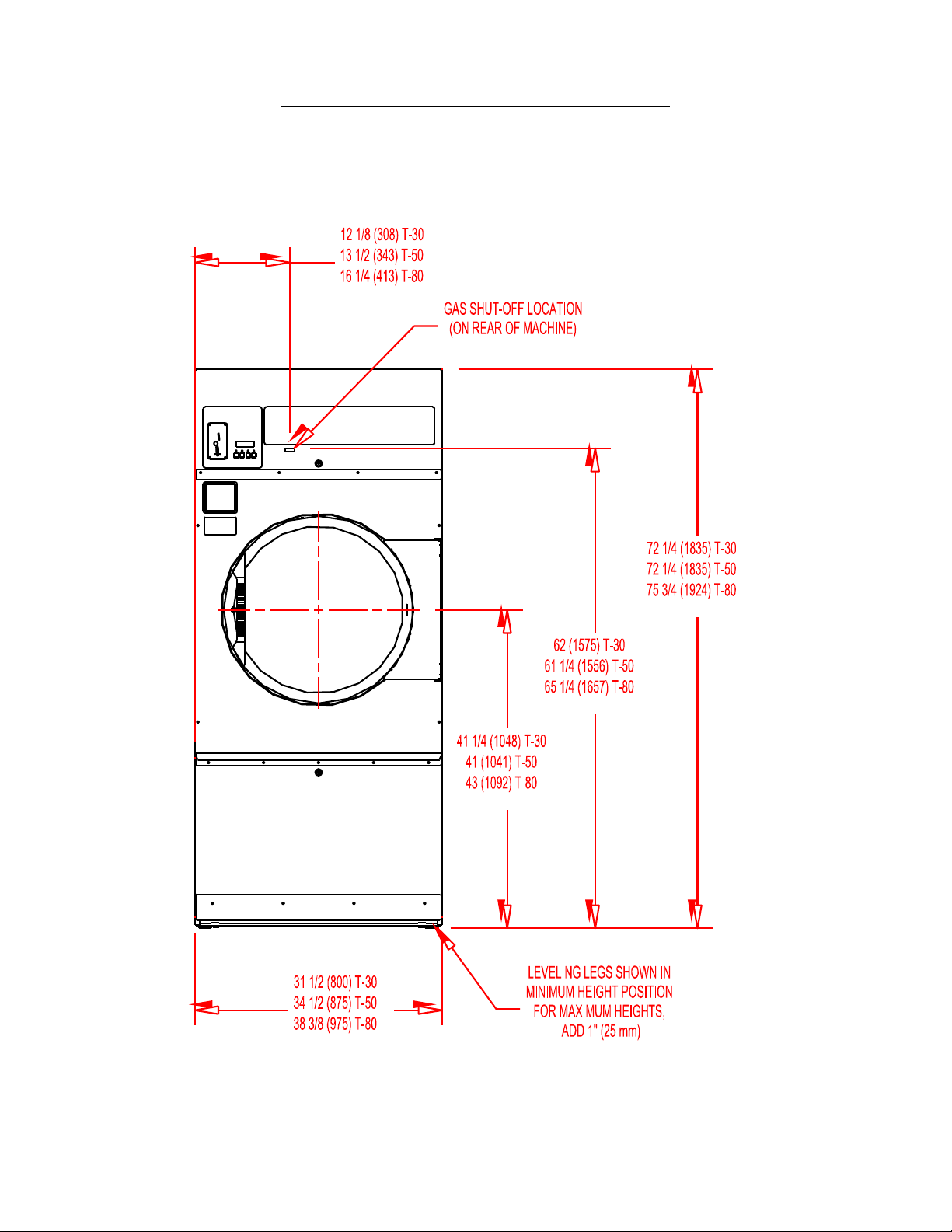
DRYER DIMENSIONS- FRONT VIEW
8514-234-001 rev. A page 6
Page 7
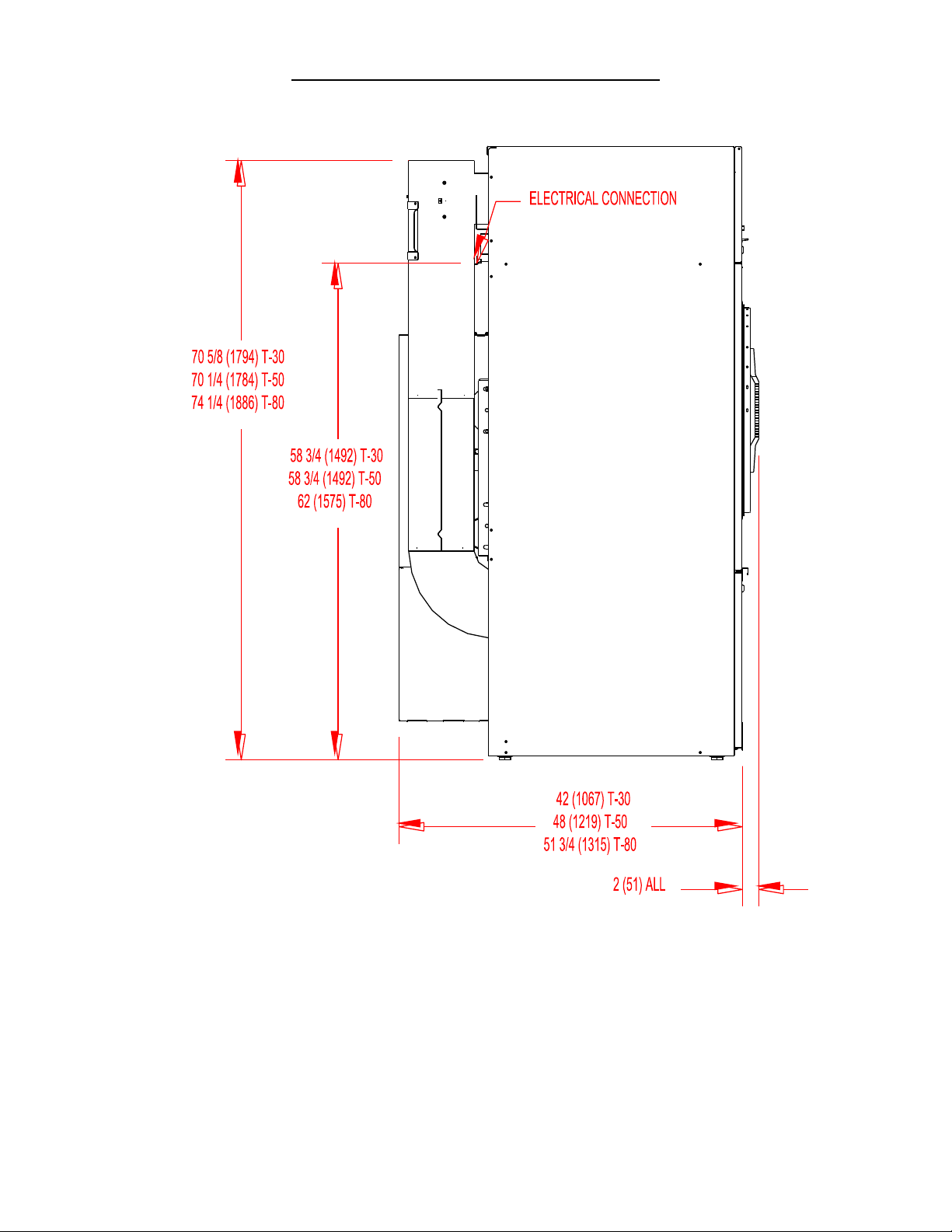
DRYER DIMENSIONS- SIDE VIEW
8514-234-001 rev. A page 7
Page 8
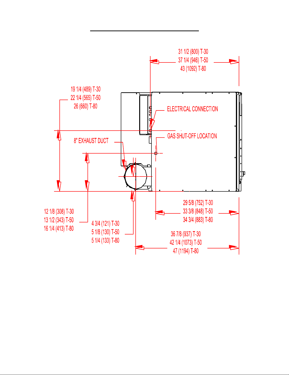
DRYER DIMENSIONS- TOP VIEW
8514-234-001 rev. A page 8
Page 9

INSTALLATION AND OPERATING INSTRUCTIONS
UNCRATING AND PLACING DRYER
Tools Required: 3/4" (19 mm) hex socket & ratchet driver, wood block 4" (100 mm) or 5" (125 mm) thick, a knife
and a groove joint pliers, which will open to 1 3/8" (35 mm).
1. Remove and discard packaging.
2. The crate base is attached to the dryer by (4) cap screws driven upward from below the crate base. Remove
crate base from dryer, by tipping dryer sidewise and place block under crate base rail in center of dryer.
Using a ratchet and 3/4" hex socket, remove and discard (2) crating bolts from side, which is raised.
Remove block from under crate base. Repeat for other side. Save the bolts for use if the dryer is ever
moved again.
3. With a walking motion move dryer completely off crate base. Save the crate base for use if the dryer is
ever moved again.
4. Slide unit into position where it will be installed. Adjust leveling legs, using the groove joint pliers, to level and
align dryer with adjacent units.
Note: If the dryer is ever moved again, the dryer should be re-mounted on its crate base and its crating bolts reinserted and tightened, in the reverse order as above.
DRYER INSTALLATION
1. CODE CONFORMITY: All commercial dryer installations must conform with local codes, or in the absence of
local codes, with the latest edition of the National Fuel Gas Code ANSI Z223.1. Canadian installations must
comply with the current Standard CAN/CGA-B149 (.1 or .2) Installation Code for Gas Burning Appliances or
Equipment, and local codes if applicable. Australian installations must meet installation requirements and pipe
sizing requirements of AS/NZA 5601. The appliance, when installed, must be electrically grounded in
accordance with the latest edition of the National Electric Code, ANSI/NFPA70, or, when installed in
Canada, with Standard CSA C22.1 Canadian Electrical Code Part 1.
2. INSTALLATION CLEARANCES: This unit may be installed at the following alcove clearances:
I. Left Side 0"
II. Right Side 0"
III. Back 18" (457 mm) (Certified for 6" (150 mm) clearance; however, 18" (457 mm) clearance is
necessary behind the motors to allow servicing and maintenance.)
IV. Front 48" (1220 mm) (to allow use of dryer)
V. Top Refer to figure labeled “Vertical Clearance Dimensions”.
AB. Certification allows 0" clearance at the top 4" (100 mm) back from the front.
However, a 1/4" (6 mm) clearance should be allowed so that the upper service door
can be opened.
C. A 10" (250 mm) clearance is required from top at all other points.
VI. Floor This unit may be installed upon a combustible floor.
Do not obstruct the flow of combustion and ventilation air.
Maintain minimum of 1" (25 mm) clearance between duct and combustible material.
Refer to the label attached to the Belt Guard on the rear of the dryer for other installation information and
start-up instructions.
8514-234-001 rev. A page 9
Page 10
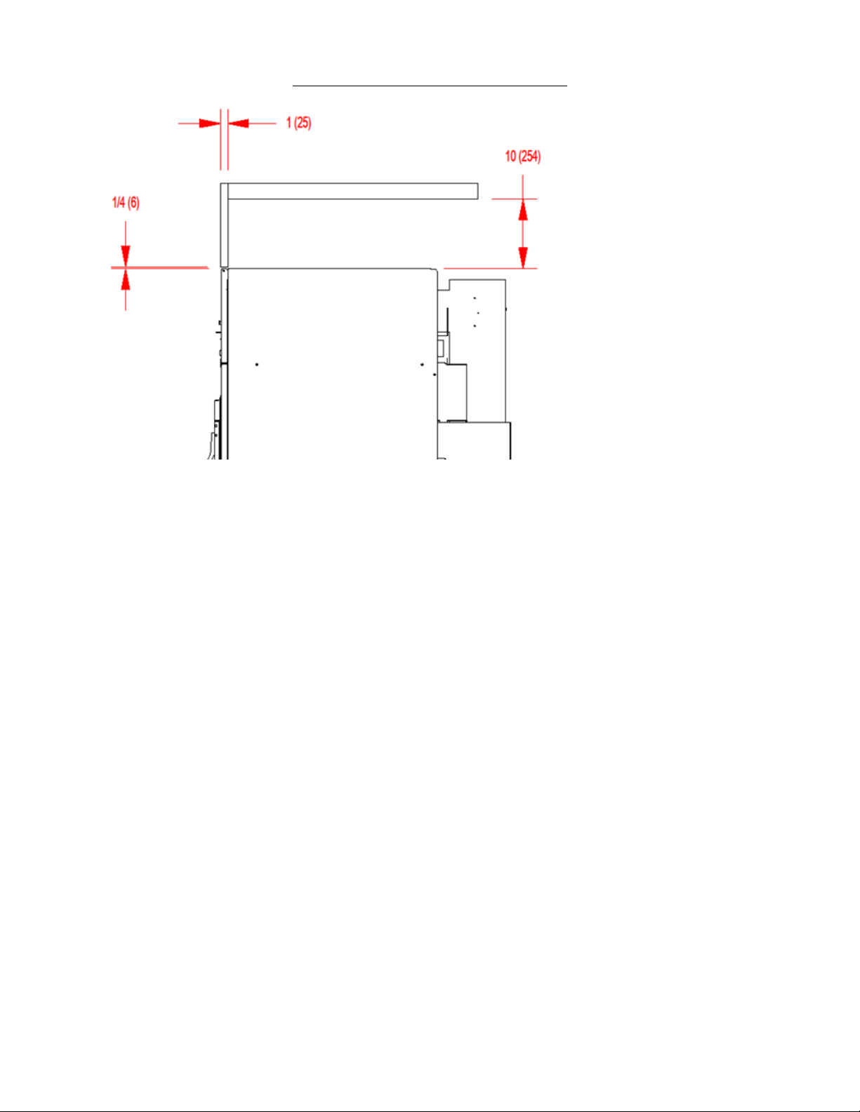
VERTICAL CLEARANCE DIMENSIONS
3. MAKE-UP AIR: Adequate make-up air must be supplied to replace air exhausted by dryers on all types of
installations. Refer to specifications for the minimum amount of make-up air opening to outside for each dryer.
This is a net requirement of effective area. Screens, grills or louvers, which will restrict the flow of air, must be
considered. Consult the supplier to determine the free area equivalent for the grill being used. The source of
make-up air should be located sufficiently away from the dryers to allow an even airflow to the air intakes
of all dryers. Multiple openings should be provided.
The sources of all make-up air and room ventilation air movement to all dryers must be located away
from any dry cleaners. This is necessary so that solvent vapors will not be drawn into the dryer inlet
ducts. Dry cleaner solvent vapors will decompose in contact with open flame such as the gas flame present
in clothes dryers. The decomposition products are highly corrosive and will cause damage to the dryer(s)
ducts and clothes loads.
4. ELECTRICAL REQUIREMENTS. The electrical power requirements necessary to operate the unit satisfactorily
are listed on the serial plate located on the back panel of each dryer and in the specifications section of
this manual. The electrical connection should be made to the terminal board, on the rear of the unit. It is
absolutely necessary that the dryer be grounded to a known ground. Individual circuit breakers for each
dryer are required.
5. GAS REQUIREMENTS. The complete gas requirements necessary to operate the dryer satisfactorily are
listed on the serial plate located on the back panel of the dryer and in the specifications section of this
manual. The inlet gas connection to the unit is 1/2-inch pipe thread. However, the size of the piping to supply
the dryer should be determined by reference to the National Fuel Gas Code ANSI Z223.1A and consultation
with the local gas supplier.
A joint compound resistant to the action of liquefied petroleum gases should be employed in making pipe
connections.
A 1/8-inch NPT plugged tapping, accessible for test gage connection, must be installed immediately
upstream of the gas supply connection to the dryer.
8514-234-001 rev. A page 10
Page 11

A drip tee is provided in the unit gas piping to catch dirt and other foreign articles.
All pipe connections should be checked for leakage with soap solution. Never check with an open flame.
For altitudes above 2,000 feet (610m), it is necessary to derate the BTU input. Contact your local
distributor for instructions.
L.P. gas conversion kits are available for this dryer. Contact your local distributor.
CAUTION: The dryer and its individual shutoff valve must be disconnected from the gas supply piping
system during any pressure testing of that system at test pressures in excess of 1/2 psig (34.5 mbar).
The dryer must be isolated from the gas supply piping system by closing its individual manual shutoff
valve during any pressure testing of the gas supply piping system at test pressures equal to or less than
1/2 psig (34.5 mbar).
6. EXHAUST INSTALLATION. (Refer to Figure 3) Exhausting of the dryer(s) should be planned and
constructed so that no air restrictions occur. Any restriction due to pipe size or type of installation can
cause slow drying time, excessive heat, and lint in the room.
From an operational standpoint, incorrect or inadequate exhausting can cause a cycling of the high limit
thermostat, which shuts off the main burners and results in inefficient drying.
The exhaust duct connection near the top of the dryer will accept an 8” (200 mm) round duct. Individual
exhausting of the dryers is recommended. All heat, moisture, and lint should be exhausted outside by
attaching a pipe of the proper diameter to the dryer adapter collars and extending it out through an
outside wall. This pipe must be very smooth on the inside, as rough surfaces tend to collect lint, which
will eventually clog the duct and prevent the dryer from exhausting properly. All elbows must be
smooth on the inside. All joints must be made so the exhaust end of one pipe is inside the next one
downstream. The addition of an exhaust pipe tends to reduce the amount of air the blower can exhaust.
This does not affect the dryer operation if held within practical limits. For the most efficient operation, it
is recommended that no more than 14 ft. (4.25 m) of straight 8 in. diameter pipe with two right angle
elbows be used for each cylinder.
Maintain a minimum of 1” (25mm) clearance between duct and combustible material.
If the exhaust pipe passes through a wall, a metal sleeve of slightly larger diameter should be set in the
wall and the exhaust pipe passed through this sleeve. This practice is required by some local codes and is
recommended in all cases to protect the wall.
This type of installation should have a means provided to prevent rain and high winds from entering the
exhaust when the dryer is not in use. A hood with a hinged damper can be used for this purpose.
Another method would be to point the outlet end of the pipe downward to prevent entrance of wind
and rain. In either case, the outlet should be kept clear, by at least 24 in. (610 mm) of any objects,
which would cause air restriction.
Never install a protective screen over the exhaust outlet.
When exhausting a dryer straight up through a roof, the overall length of the duct has the same limits as
exhausting through a wall. A rain cap must be placed on top of the exhaust and must be of such a type
as to be free from clogging. The type using a cone shaped “roof” over the pipe is suitable for this
application.
Exhausting the dryer into a chimney or under a building is not permitted. In either case there is a danger
of lint buildup, which can be highly combustible.
Installation of several dryers, where a main discharge duct is necessary, will need the following
considerations for installation (see Figure 3). Individual 8” (200 mm) exhaust ducts from each dryer
should enter main discharge duct at a 45-degree angle in the direction of discharge airflow.
8514-234-001 rev. A page 11
Page 12
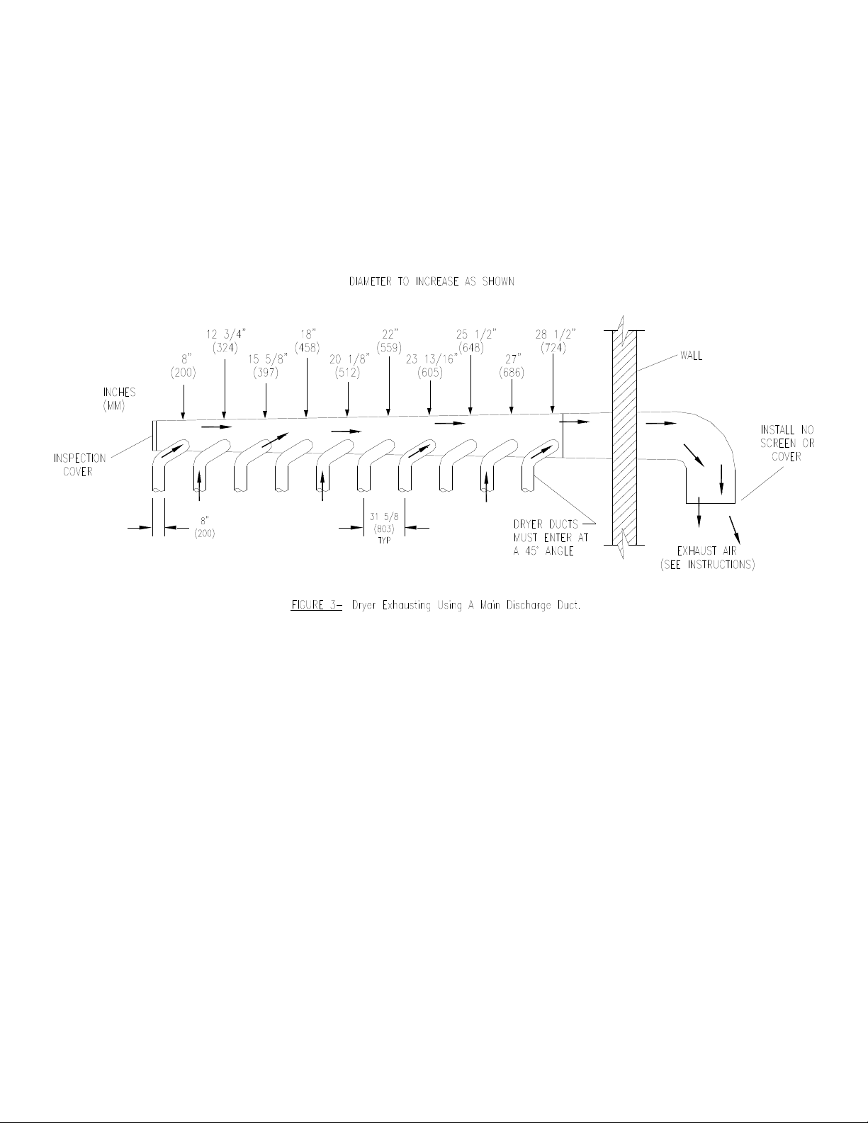
NOTE: Never install the individual ducts at a right angle into the main discharge duct.
The individual ducts from the dryers can enter at the sides or bottom of the main discharge
duct. Figure 3 indicates the various round main duct diameters to use with the individual
dryer ducts. The main duct can be rectangular or round, provided adequate airflow is
maintained. The total exhausting (main discharge duct plus duct outlet from the dryer)
should not exceed the equivalent of 14 ft. (4.25 m) and two elbows. The diameter of the
main discharge duct at the last dryer must be maintained to exhaust end.
NOTE: A small diameter duct will restrict airflow; a large diameter duct will reduce air
velocity - both contributing to lint build up. An inspection door should be provided for
periodic clean out of the main duct.
7. DRYER IGNITION (SOLID STATE IGNITION): The solid-state ignition system lights the main burner gas by spark.
The gas is ignited and burns only when the gas-relay (in the electronic controller) calls for heat. The procedure for
first-time starting of a dryer is as follows.
i. First review and comply with the "Warnings About Use and Operation" found on the inside front cover
of this manual. Be sure electrical power is connected correctly. The dryer must be properly grounded.
ii. Make sure all gas supply lines are purged of air. Close the main gas shut-off valve and wait for five
minutes before turning it back on.
iii. Turn on the main electrical power switch. The dryer may be started by following the "Operating
Instructions" found later in this manual.
iv. Natural gas and LPG fired dryers operate in the same manner. When the gas valve relay contacts are
closed (indicating a demand for heat), the solid-state ignition control will automatically supply energy to the
redundant gas valve. Sparking will continue until a flame is detected by the sensing probe, but not longer than
ten seconds. If the gas fails to ignite in 10 seconds, the gas valve closes and the gas system pauses to allow gas to
purge from the inside of the dryer. After the pause, the ignition control repeats the ignition trial cycle twice more.
If the gas system fails to detect ignition after the three attempts, the system will "lock out". No further attempts
will be performed automatically. To reset the ignition control electrical power to the ignition control must be
interrupted. This can be done by opening the dryer door (stopping the dryer) for 15 seconds. Closing the door and
pushing the "Start" button will repeat the ignition trial cycle.
8514-234-001 rev. A page 12
Page 13
DRYER SHUTDOWN
To render the dryer inoperative, turn off the main gas shut off valve and disconnect the electrical supply to the
dryer.
NOTE: It is recommended that the installer test the dryer for operation and instruct the
user before leaving the installation.
OPERATING INSTRUCTIONS
STARTING THE DRYER
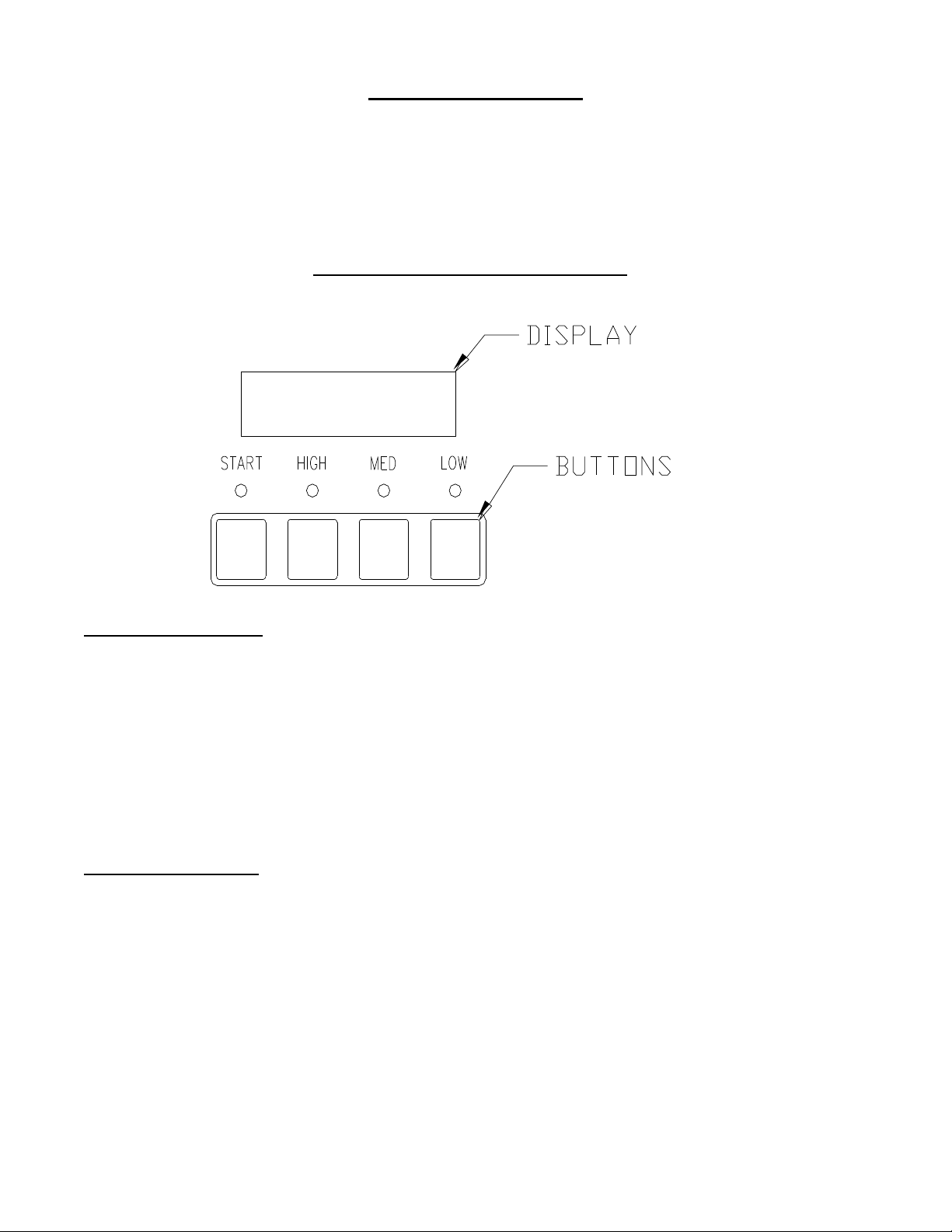
1. The display on the dryer control will show the required vend amount when in i dle mode. Once the door is
opened it will prompt the user to add money. Load clothes into the dryer. Close the door completely.
2. Deposit coins equal to or greater than the displayed vend price. The display on the control will prompt the user to
choose a drying temperature.
3. Select the drying temperature by pressing the appropriate button for “high”, “med” (medium) or “low”. This will
turn on the red indicator light showing the selected temperature.
4. Press the “start” button to start dryer. This will turn on the green indicator light. The drying time purchased is
now displayed. The colon begins flashing to indicate that the timer is counting down.
RUNNING THE DRYER
-Opening the door will stop the dryer, but the timer will continue to count down. The dryer will restart, if time
has not expired, upon closing the door and pressing the “start” button.
-Selected temperature may be changed at any time (unless Temperature Pricing feature is activated).
-Running time may be extended by depositing coins and pressing the “start” button. Unless time has expired,
the controller will accept coins whether or not the original vend price is equaled.
-If time has run out, the dryer must be restarted as if it was at the beginning of drying the load, which requires
meeting or exceeding the vend price.
-Clothes should be removed promptly after the cycle is completed to prevent excessive wrinkling.
8514-234-001 rev. A page 13
Page 14
-Cool-down time (owner programmable) is always part of the cycle time purchased by the customer. For example,
if the cool-down time is 2 minutes, then the last 2 minutes of the cycle will have no heat.
PROGRAMMING THE DRYER CONTROL
The dryer control can be programmed to prompt the user for alternate vend prices, change dryer cycle times,
temperatures and many other options. This can be accomplished in two ways:
1. Manual programming utilizing the “Start”, “High”, “Medium” and “Low” buttons.
2. USB download of a pre-programmed User File. For instructions on using the USB download feature,
please contact your local Dexter distributor.
MANUAL PROGRAMMING:
The dryer must be in idle mode for the manual programming menus to be accessed. Idle mode is when the dryer
is not actively running a drying cycle and the vend price is displayed on the screen.
To enter the manual programming mode, the upper service door on the dryer must be unlocked and lifted to
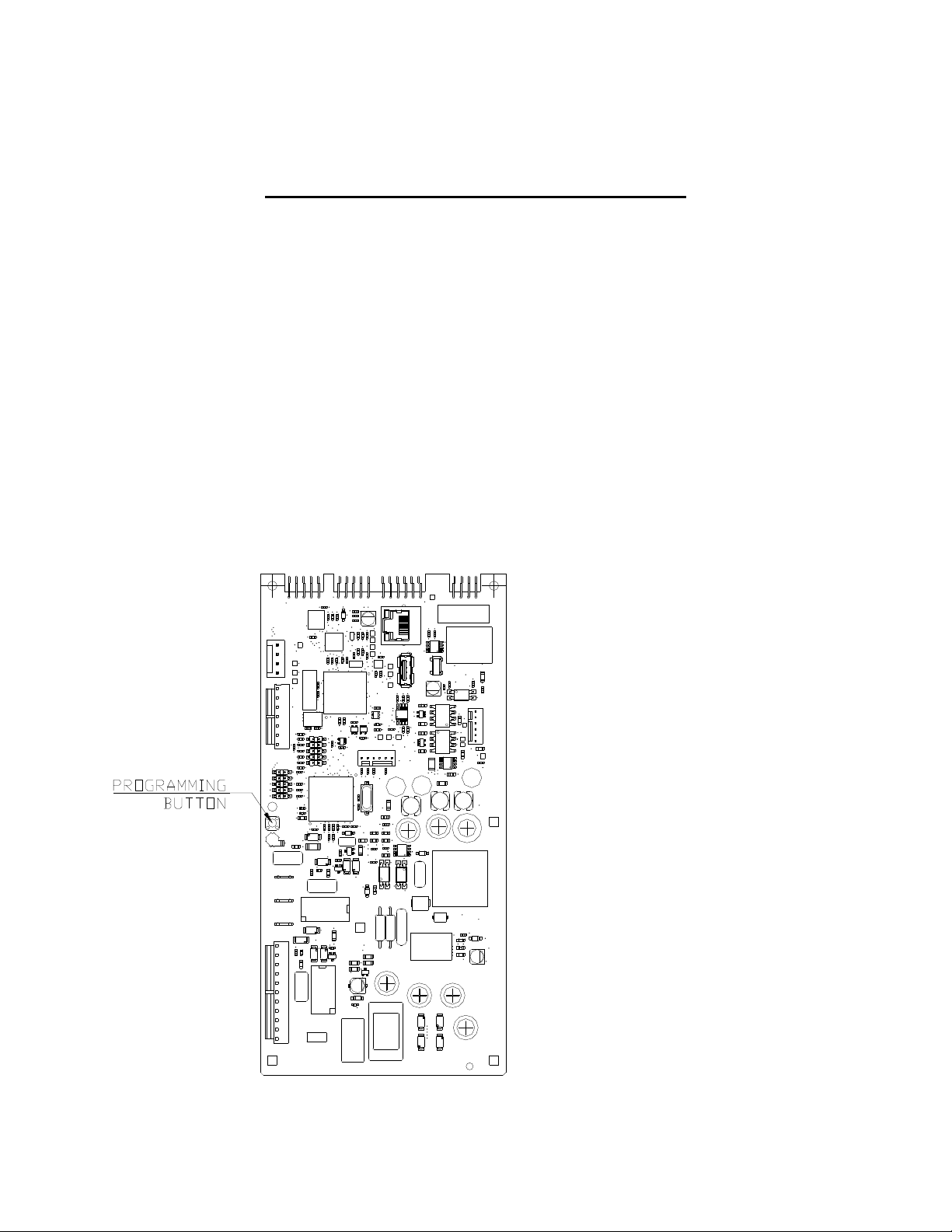
reveal the back side of the control. The programming button is found in the location shown below. The
programming button is then pressed for 1 second. The control should display “DRYER PROGRAMMING”.
See the figure below for the location of the programming button on the dryer control. Please note, this is the
control as viewed from the underside of the lifted service door.
8514-234-001 rev. A page 14
Page 15
Button Name
Alternate Function in Programming Mode
Start
Becomes the action to accept the displayed option or the “Enter”
key
High
Becomes the action to move UP through displayed options (Press
& hold for accelerated scrolling)
Medium
Becomes the action to move DOWN through displayed options
(Press & hold for accelerated scrolling)
Low
Becomes the action to move back a step (1 press) or EXIT from
programming mode (press for 3 seconds)
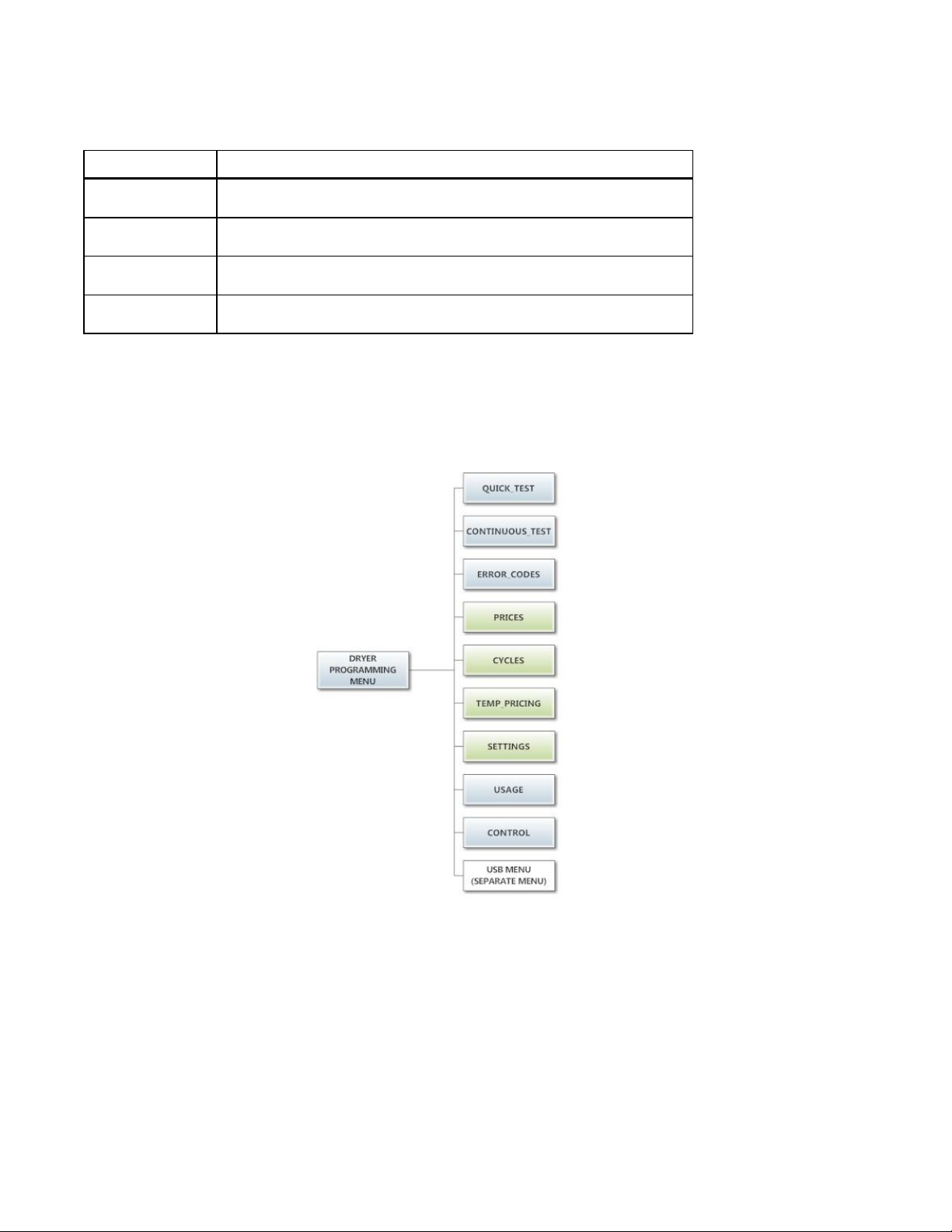
When manual programming mode is entered, the “Start”, “High”, “Medium” and “Low” buttons perform alternate
functions.
These alternate functions allow the user to move through a menu of options to choose various programmable
settings. The figure below shows the top level menu. Choosing an option from the top level menu will then
display the next level of options (the sub menu).
Quick Test Option:
When the Quick Test Option is chosen, the dryer will begin a shortened dry cycle without the displayed vend
price being met. The purpose of this shortened cycle is to test all major components for proper operation.
Error Codes should all function normally during this test. The display will show customer prompts in a similar way
to a normal dry cycle.
Continuous Test Option:
Similar to the Quick Test, when the Continuous Test Option is chosen, the dryer will begin a dry cycle without the
displayed vend price being met. However, in this case, it will be a continuously-running cycle. It will not time out
after any designated amount of time.
8514-234-001 rev. A page 15
Page 16
CAUTION: This option is meant for factory use only. Do not operate the dryer with this cycle active without
Base Vend Price
$1.00
Base Vend Time
30 minutes
Extend Dry Price
$.25
Extend Dry Time
8 minutes
factory authorization.
Error Code Historical Log:
The last five occurring error codes will be stored in the control with a time and date stamp. The purpose of this
option is only to observe the history of these code occurrences (no changes can be made).
The time is based off the Real Time Clock, but potentially shifted by the user’s manual programming changes
(Shift Hours option) and/or network time override. As additional error codes occur, the oldest of the five logged
codes is cleared from memory.
Prices Option:
This option allows the user to set values for coin acceptor inputs, vend price & time and extend dry price & time.
It also allows the user to return the values to factory defaults. After changing prices using the “Up” or “Down”
buttons, the “Enter” button must be pressed again for the control to store the changes that have been made.
Note that, in general, time values are set in 1 minute increments. This can be changed to 30 second increments,
by changing the “Display Time” to “MIN+SEC” (refer to the “Settings” section”).
1. “RIGHT COIN” and “LEFT COIN” are the two possible inputs from coin acceptors.
2. “PRICE SET VEND” is the actual Base Vend Price (or Vend Price A) that is shown on the control display.
The value can be increased or reduced even down to “0”. In this case, the displays will prompt “FREE”
and the cycle will start as soon is the “Start’ button is pressed (without any vend price being met).
3. “TIME SET VEND” is the cycle time that the customer has available once they’ve met the Base Vend
Price.
4. “FREE SET TIME” is the cycle time that the customer has available if the Base Vend Price is set to “FREE”.
5. “EXTEND DRY” sets the price and time for additional drying time that becomes available after the
customer has already met the Base Vend Price.
To reset either the coin acceptor inputs or the vend price to factory default, press “Enter” when the “DEFAULT”
prompt is shown. Press “Enter” again when the “RESET” prompt is shown to confirm the action.
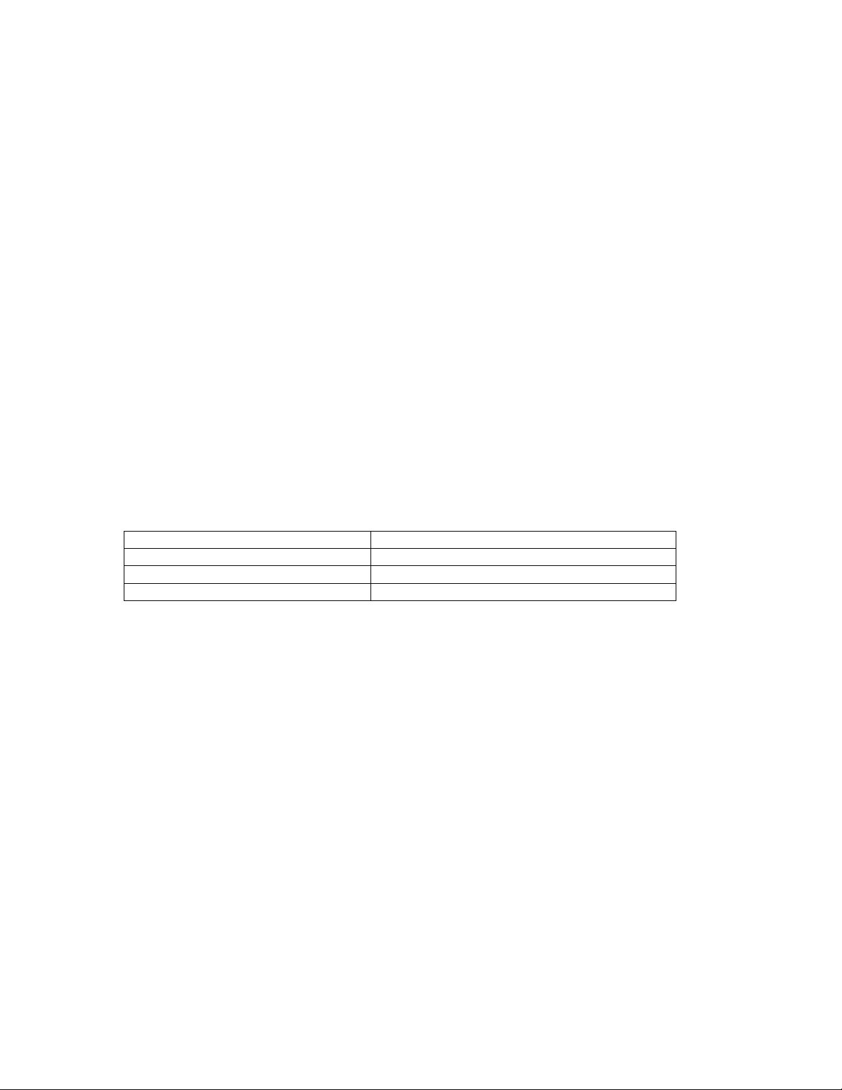
Example- A store owner has programmed the control for the following values:
In this case, the customer adds 4 quarters to satisfy the $1.00 Vend Price. The display shows 30 minutes
of drying time. At this point, if an additional quarter is added, the customer display shows an additional 8
minutes of drying time (38 minutes total) as per the Extend Dry Price & Time.
The customer starts the drying cycle and at 25 minutes into the cycle (13 minutes displayed), they add
an additional quarter. The controller adds 8 minutes to the displayed time again (21 minutes total) as per
the Extend Dry Price & Time.
“AFTER CYCLE” allows the user to choose whether a customer is allowed to add “EXTEND DRY” time for up to 30
seconds after the dryer door is opened after a completed cycle.
8514-234-001 rev. A page 16
Page 17
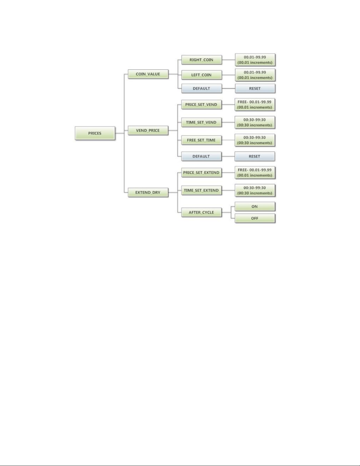
The figure below shows the sub menu options for Prices:
8514-234-001 rev. A page 17
Page 18

Cycles Option:
This option allows the user to set temperature and cooldown information for the drying cycle. It also allows the
user to return the values to factory defaults.
1. “TEMP SETTINGS” allows the user to make adjustments, within a designated range, to the cycling
temperature for each of the “Low”, “Medium” and “High” customer choices.
2. In addition, on the “Low” setting, the user can reduce the cycling temperature below 110 degrees F. In
this case, when the customer chooses the “Low” setting, the dryer will not turn on the gas valve. When
checked, the displayed temperature will read “NO HEAT”.
3. “COOLDOWN” allows the user to change the designated time at the end of a cycle where the gas valve
relay is turned off. On “High” and “Medium” temperature settings, the designated time cannot be reduced
to less than 2 minutes.
4. “DEFAULT TEMP” allows the user to choose which general temperature setting, “High”, “Medium” or
“Low”, the control will default to at the beginning of each cycle if the customer does not make a choice.
5. “ANTI WRINKLE” is a feature that periodically rotates the dryers after a cycle is complete. If the door was
closed at the end of the cycle, and is left closed for 5 minutes, the enunciator will sound and the display
begins scrolling “ANTI WRINKLE”. 5 seconds later, the dryer motor will turn on for 60 seconds and then
turn off. The gas valves will not be turned on. The “ANTI WRINKLE” message will continue throughout
the time that the motor is turned on. The user can choose to enable or disable this feature.
To reset all values in the Cycles option to factory default, press “Enter” when the “DEFAULT” prompt is shown.
Press “Enter” again when the “RESET” prompt is shown to confirm the action.
8514-234-001 rev. A page 18
Page 19
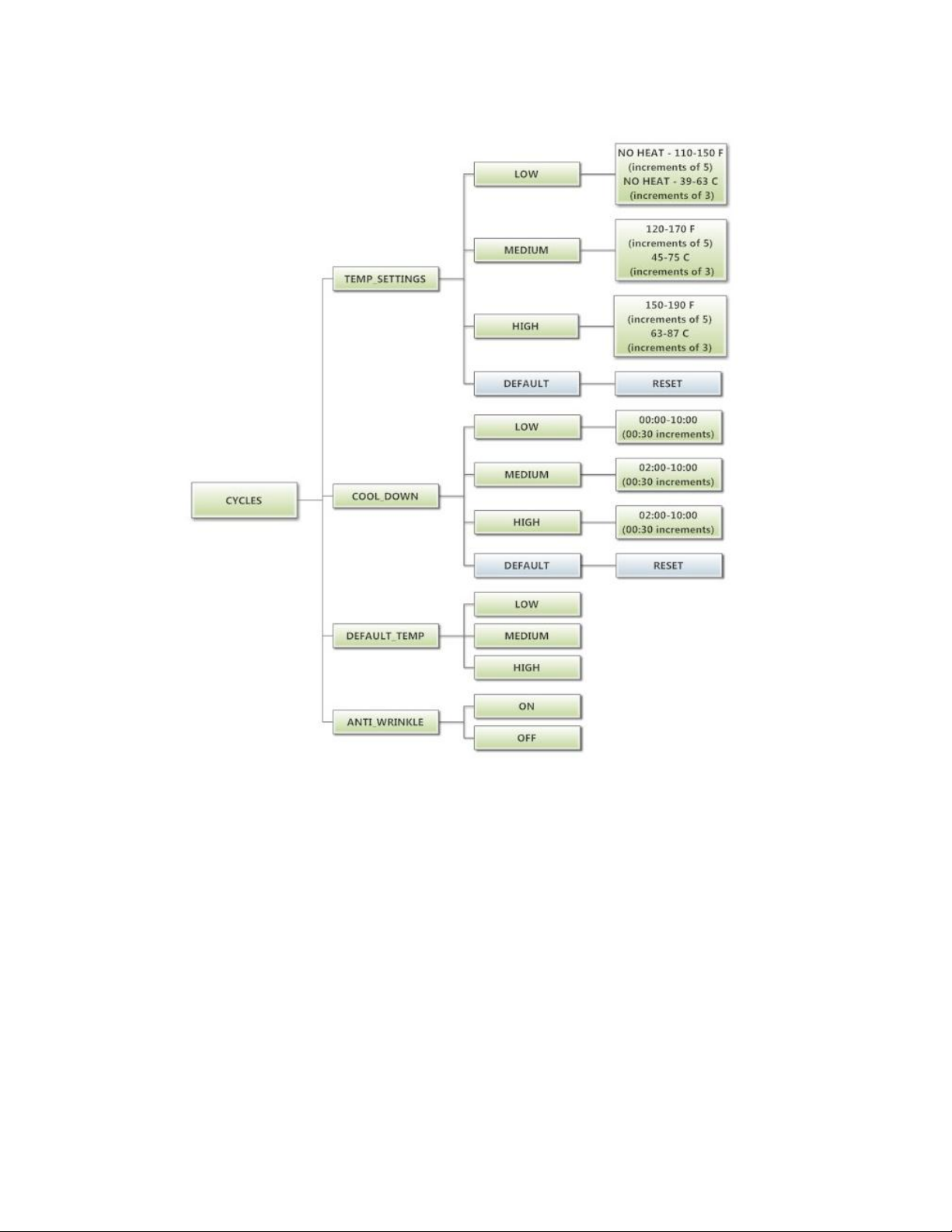
The figure below shows the sub menu options for Cycles:
8514-234-001 rev. A page 19
Page 20
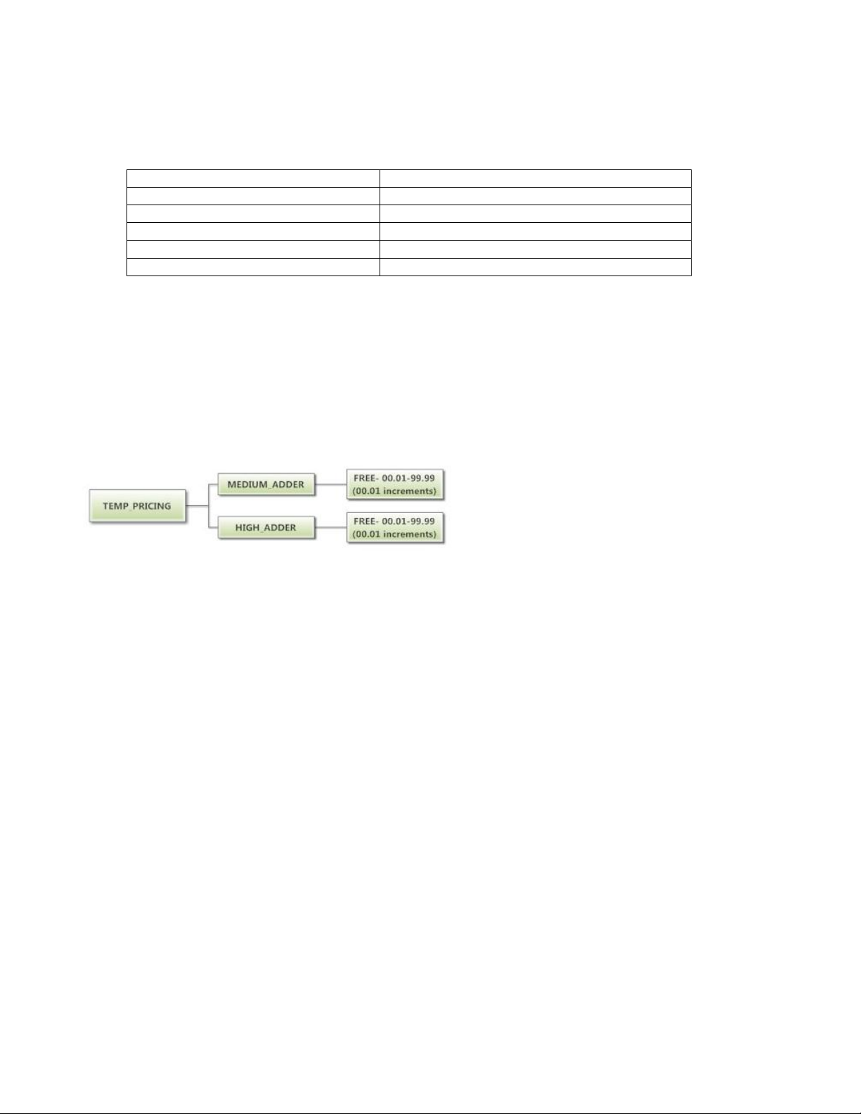
Vend Price
$1.00
Vend Time
30 minutes
Extend Dry Price
$.25
Extend Dry Time
8 minutes
Medium Adder
$.25
Hot Adder
$.50
Temperature Pricing Option:
This option allows the user to require additional vend amounts be added based on the drying
temperature chosen by the customer. This pricing adder is effective only for the Base Vend Price (it does not
affect the Extend Dry Price). It allows a pricing adder separate for “Medium” and “Hot” temperature settings.
Example- A store owner has programmed the control for the following:
In this case, the Vend Price is displayed as:
$1.00 if Low Temperature is chosen
$1.25 if Medium Temperature is chosen
$1.50 if Hot Temperature is chosen
When Temperature Pricing Adders are in place (user has chosen a higher value than $0.00), if the customer
attempts to change their temperature selection from a lower temperature to a higher one during a drying cycle,
there will be no change in the temperature selection. The higher temperature buttons are disabled until the
drying cycle is complete and a new Vend Price is required.
The figure below shows the sub menu options for Temperature Pricing:
8514-234-001 rev. A page 20
Page 21
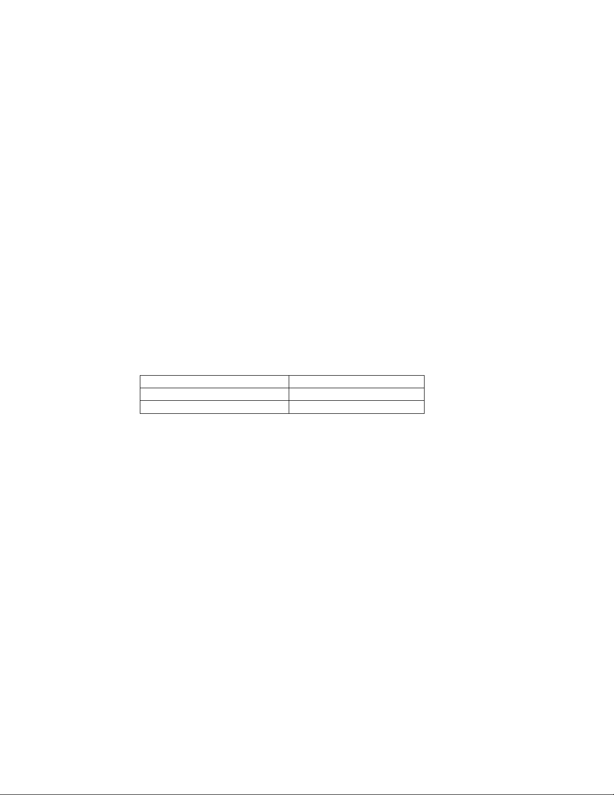
Central Pay “OFF”
Central Pay “ON”
Left Coin Input
Upper Dryer Input
Right Coin Input
Lower Dryer Input
Settings Options:
The Settings options allow for the user to make various programming changes to change how the control
operation affects the customer. See below for detailed information on each next level option.
1. “Decimal Point”: If the user programs the Decimal Point to “OFF”, control display will not show a decimal
point on any vend price values. The factory default is “ON”.
2. “Display Time”: If the user programs this value to “MIN”, then minutes only will be shown for the cycle
time. If it is programmed to “MIN+SEC”, then minutes and seconds will be shown. This also allows other
programming changes, involving time, to be made in either minute increments or minutes & seconds
increments, as desired.
3. “Temp Scale”: If the user programs this value to “F”, then the temperatures will be displayed in
Fahrenheit units. If it is programmed to “C”, then the temperature will be in Celsius units.
4. “Sounds”: If the user programs the Sounds to “OFF”, the control will not sound the enunciator at the end
of a dry cycle. The factory default is “ON”.
5. “Password”: If the user programs the password to any value other then 0000, the control will prompt the
user to enter a password (the programmed value) before manual programming can be accessed. The
factory default is “0000” (no password).
a. Note that if the user forgets the Password, it can be reset to factory default (no password), by
performing a hard reset on the control. Please refer to the appropriate section of this manual to
understand how to perform a hard reset.
b. The individual digits of the Password can be set by using the “Up” or “Down” buttons to change
the number that is flashing. Once the desired number is chosen for a single digit, press the
“Enter” button to move to the next one. Once all four desired digits are chosen, the “Enter”
button must be held down for 3 seconds to confirm that the complete password should be set.
6. “Central Pay”: This feature is used primarily for Stack Dryers. If the user programs this value to “ON”, the
left and right coin inputs become upper and lower dryer coin inputs.
A system can then be installed that will register coin inputs per individual dryer remotely from a Central
Pay kiosk. The left and right coin prices must be appropriately programmed. When this option is enabled,
the controller will only display customer prompts for a designated dryer. This designated dryer is
determined when coins are inserted at the Central Pay kiosk.
7. “Language”: The control uses English for the default language of the customer prompts. Alternatively, the
user can choose Spanish or French for the customer display prompts. However, all other prompts, such
as Manual Programming, USB Programming and any Error Codes will still display in English.
8. “Shift Hours”: This feature allows the user to shift the time used by the control from the time kept
internally by the control. The control uses a Real Time Clock (RTC) to internally track the time and date.
The RTC continues operation even if the control loses external power. The RTC is set for Central
Standard Time and no daylight savings. Because the machine may be located in another time zone, the
user can choose to create an alternate time & date that tracks in parallel to the RTC. When this alternate
time is chosen, or shifted from the RTC, the alternate time will be used to, for example, track error code
occurrences and set time-of-day pricing changes.
a. The hours in “SHIFT HOURS” can be set by using the “Up” or “Down” buttons to change the
number that is flashing. Once the desired hour shift is chosen, press the “Enter” button to move
to the minutes. Once the hours and minute shift are both chosen, the “Enter” button must be
held down for 3 seconds to confirm that the complete shifted time is set.
9. “Time”: The control uses a Real Time Clock (RTC) to internally track the time and date. The RTC
continues operation even if the control loses external power. The RTC is set for Central Standard Time
and no daylight savings. However, if a problem occurs and the RTC time is not accurate, it can be reset
to the current time using this option.
a. The hours in “TIME” can be set by using the “Up” or “Down” buttons to change the number that
is flashing. Once the desired hour is chosen, press the “Enter” button to move to the minutes.
Once the hours and minute are both chosen, the “Enter” button must be held down for 3 seconds
to confirm that RTC is meant to be reset to the complete entry.
8514-234-001 rev. A page 21
Page 22
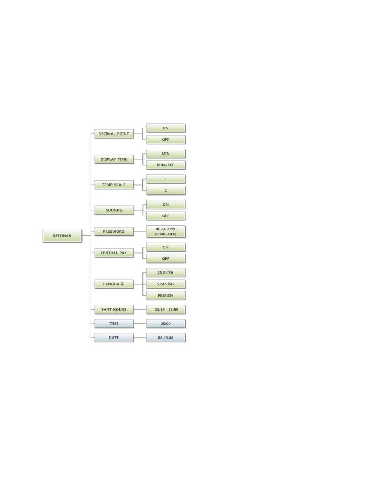
10. “Date”: Similar to “Time”, if a problem occurs and the RTC date is not accurate, it can be reset to the
current date using this option.
a. The day of the month in “DATE” can be set by using the “Up” or “Down” buttons to change the
number that is flashing. Once the desired day of the month is chosen, press the “Enter” button to
move to the month of the year. Once the desired month of the year is chosen, press the “Enter”
button to move to the year. Once the day, month and year are all chosen, the “Enter” button
must be held down for 3 seconds to confirm that RTC is meant to be reset to the complete entry.
To reset all values in the Settings options to factory default, press “Enter” when the “DEFAULT” prompt is shown.
Press “Enter” again when the “RESET” prompt is shown to confirm the action.
The figure below shows the sub menu options for Settings:
8514-234-001 rev. A page 22
Page 23
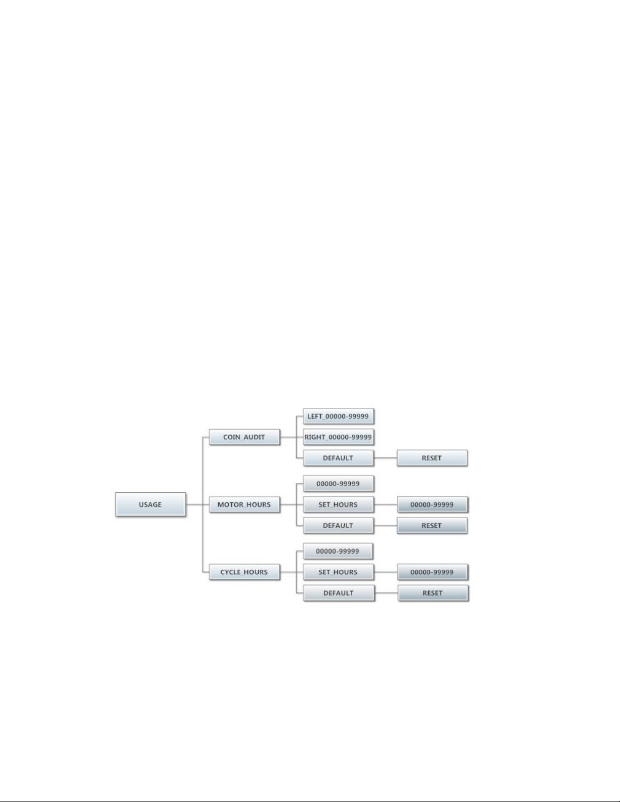
Usage Menu:
The Usage menu allows for the user to track data about machine usage. See below for detailed information on
each sub menu option.
1. “Coin Audit”: The coin audit field shows the accumulation of coin pulses that were sent to the control
over each of the left and right coin inputs. Note that this is a count of coin pulses, not an accumulated
report of vend value.
a. The user can also return the coin audit amounts to the factory default setting (zero). To reset all
coin audit values, press “Enter” when the “DEFAULT” prompt is shown. Press “Enter” again when
the “RESET” prompt is shown to confirm the action.
2. “Motor Hours”: The motor hours field shows the accumulated hours of operation for the dryer motor. In
many cases, it will match the cycle hours of the machine. However, separate fields are provided in the
event that a motor is replaced on a machine. The user can set the motor hours to a designated number.
For example, if it is necessary to replace the control on a machine, the new control could be programmed
to show the motor hours that were recorded by the previously installed control. The individual digits of
the hours count can be set by using the “Up” or “Down” buttons to change the number that is flashing.
Once the desired digit of the hours is chosen, press the “Enter” button to move to the next digit. Once
the complete hours are chosen, the “Enter” button must be held down for 3 seconds to confirm the
action.
a. The user can also return the motor hours to the factory default setting (zero). To reset the motor
hours, press “Enter” when the “DEFAULT” prompt is shown. Press “Enter” again when the
“RESET” prompt is shown to confirm the action.
3. “Cycle Hours”: The cycle hours field shows the accumulated hours of operation for the dryer. In many
cases, it will match the motor hours of the machine. However, separate fields are provided in the event
that a motor is replaced on a machine. See the Motor Hours description for more information.
The figure below shows the sub menu options for Usage:
8514-234-001 rev. A page 23
Page 24
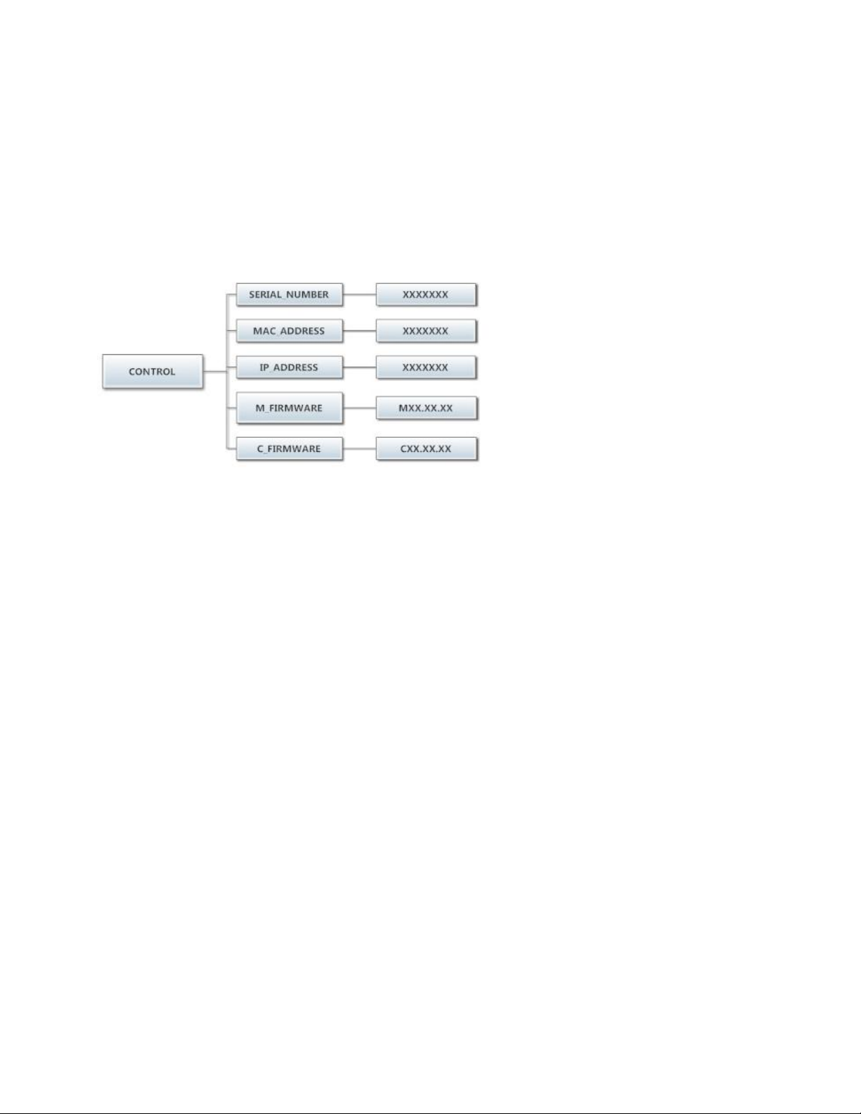
Control Menu:
The Control menu allows for the user to observe important technical information for the control. No changes can
be made at this menu. See below for detailed information on each sub menu.
1. “Serial Number”: This is the control serial number.
2. “MAC Address”: The MAC Address is a unique identifier designated to the control by the manufacturer. It
allows the control to be recognized by network routers.
3. “IP Address”: The IP Address is the identifier given to the control by a network system.
4. “M Firmware”: The M Firmware is the Main Firmware currently loaded onto the control.
5. “C Firmware”: The C Firmware is the Communications Firmware currently loaded onto the control.
The figure below shows the sub menu options for Control:
8514-234-001 rev. A page 24
Page 25
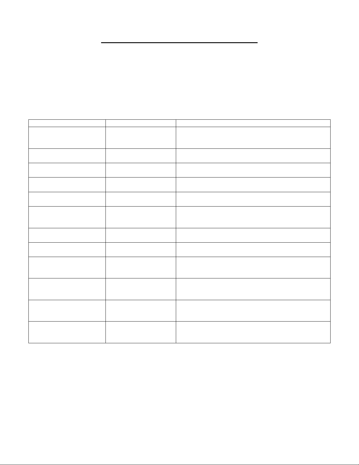
Symptom
Probable Cause
Suggested Remedy
Tumbler Does not turn
Control
Check that Control Display shows time available for
drying. If not, deposit money as needed.
Loading Door
Check that Loading Door is completely closed
Lint Compartment Door
Check that Lint Compartment Door is completely closed.
Drive Belts
Check drive belts for excessive wear. Replace as needed.
Tumbler Turns, but no
burner flame is present
Gas shut-off valve
Make sure gas shut-off valve is in the open position
Ignition Module
Follow the procedure for checking the ignition cycle
listed in Dryer Ignition section of this manual.
Slow Drying
Control
Check that proper Temperature setting is chosen.
Lint Screen
Clean Lint Screen
Air flow Restrictions/
Make-up Air
Follow installation guidelines for static back pressure and
make-up air
Exhaust
Check exhaust for obstructions, follow installation
guidelines
“Temp Sensor Short” or
“Temp Sensor Open” Error
Code displayed on control
Temperature Sensor
Press programming button to clear Error Code. If Error
code persists, contact Dexter agent for assistance
“PCB Error” or “Comm
Error” code displayed on
control
Control Error
Cycle power to dryer to clear Error Code. If Error Code
persists, contact Dexter Agent for Assistance
SERVICING AND TROUBLESHOOTING
CAUTION: Label all wires prior to disconnection when servicing controls. Wiring errors can cause improper and
dangerous operation. Verify proper operation after servicing.
ATTENTION. Lors des opérations d'entretien des commandes, étiqueter tous les fils avant de les déconnecter. Toute
erreur de câblage peut être une source de danger et de panne.
If any of the following symptoms occur on this dryer, check the suggested remedies listed below. If all probable
causes have been eliminated and the symptom still exists, contact your local Dexter agent for further
troubleshooting assistance. See contact information in Preventative Maintenance section. Parts & Service Manuals
from Dexter are also available for further troubleshooting assistance.
8514-234-001 rev. A page 25
Page 26

PREVENTIVE MAINTENANCE INSTRUCTIONS
DAILY
1. Clean the lint screen. Use a soft brush if necessary.
2. Check the lint screen for tears. Replace if necessary.
3. Clean lint from the lint screen compartment.
MONTHLY
1. Remove lint accumulation from the end bells of the motor.
2. Remove lint accumulation from front control area.
3. Remove lint and dirt accumulation from the top of the dryer and all areas above, below, and around the
burners and burner housing. Failure to keep this portion of the dryer clean can lead to a build-up of lint
creating a fire hazard.
4. Place a few drops of light oil on the clothes door hinge.
5. Grease the bearings and the shaft of the intermediate drive pulley. Use an Alemite grease gun and
Molykote BR2-S grease.
QUARTERLY
1. Check the belts for looseness, wear, or fraying.
2. Inspect the gasket of the door glass for excessive wear.
3. Check tightness of all fasteners holding parts to support channel.
4. Check tightness of all set screws.
5. Inspect the impeller for tightness of the blades to hub.
6. Check the tightness of the tumbler shaft retaining bolt.
7. Remove the air flow switch assembly and check the tumbler thru-bolts for tightness.
8. Remove lint accumulation from the primary air ports in the burners.
9. Apply a few drops of oil to each spacer tube on the tension arm assembly.
10. Grease the pivot pins and the tension arms where in contact with each other.
SEMI-ANNUALLY
1. Remove and clean the main burners.
2. Remove all orifices and examine for dirt and hole obstruction.
3. Remove all lint accumulation. Remove the front panel and the lint screen housing and remove lint
accumulation.
ANNUALLY
1. Check the intermediate pulley bearings for wear.
2. Check and remove any lint accumulation from the exhaust system.
8514-234-001 rev. A page 26
Page 27

SERVICE PARTS ____________PART NUMBER _______________
T-30 T-50 T-80
DRIVE BELT, MOTOR 9040-076-003 9040-076-006 9040-076-011
DRIVE BELT, TUMBLER 9040-073-009 9040-073-011 9040-073-012
LINT SCREEN FILTER 9822-026-002 9822-026-001 9822-031-002
For service and parts information, contact your local Dexter agent. To find your local Dexter agent, use the
Distributor Locator at the website shown below. If a Dexter agent is not available, contact Dexter Laundry,
Inc. directly as listed below:
Mailing Address: 2211 West Grimes Avenue Phone: 1-800-524-2954
Fairfield, IA 52556
USA
Website: www.dexter.com
8514-234-001 rev. A page 27
 Loading...