

Page 1
Model P2201 Cat. No. DDF211022P
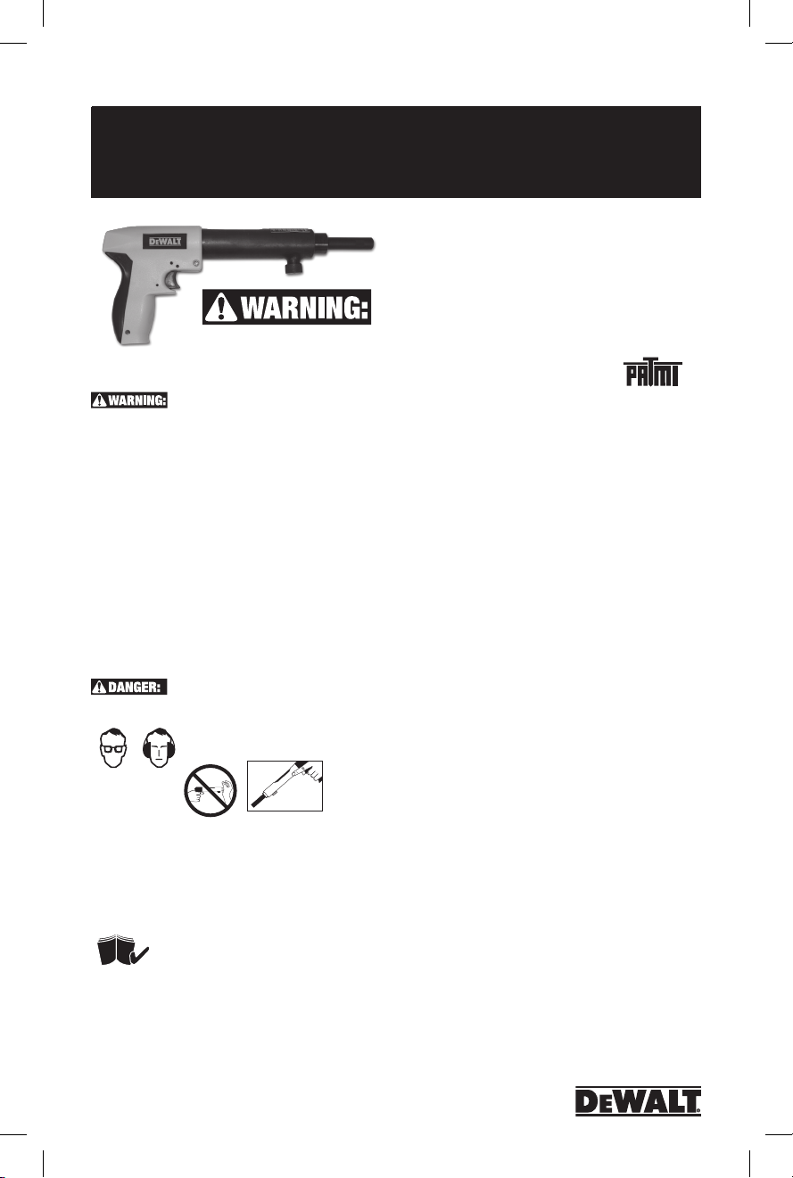
P2201
R2200
P2201
OPERATING INSTRUCTION MANUAL
Low Velocity Powder
Actuated Fastening Tool
DO NOT OPERATE THE P2201 TOOL UNTIL
YOU HAVE READ THIS MANUAL AND RECEIVED THE PROPER TRAINING
ACCORDING TO ANSI STANDARD A 10.3-1995.
STUDY THIS MANUAL CAREFULLY AND DEVELOP A THOROUGH
UNDERSTANDING OF THE CONTENTS.
PROPER TRAINING ACCORDING TO THE CURRENT ANSI
STANDARD A 10.3, SAFETY REQUIREMENTS FOR POWDER
ACTUATED FASTENING SYSTEMS MUST BE COMPLETED AND
A D
EWALT QUALIFIED OPERATOR CARD MUST BE OBTAINED
PRIOR TO OPERATION OF THE TOOL. STATE, LOCAL, OR
OTHER REGULATIONS SHOULD ALSO BE FOLLOWED. LAWS,
REGULATIONS, AND STANDARDS REGARDING THE USE
OF POWDER ACTUATED TOOLS MAY PERIODICALLY BE
REVISED. ANY SUCH REVISIONS MAY CHANGE THE SAFETY
AND OPERATING PROCEDURES DESCRIBED IN THIS MANUAL.
D
EWALT, INC. IS NOT RESPONSIBLE FOR ANY SUCH REVISIONS
WHICH OCCUR AFTER PUBLICATION OF THIS MANUAL. IT IS THE
RESPONSIBILITY OF THE USER TO MAINTAIN FAMILIARITY WITH
THE CURRENT LAWS, REGULATIONS, AND STANDARDS THAT
APPLY TO THE POWDER ACTUATED TOOL.
NEVER CLOSE TOOL WITH ANY PART OF HAND OVER MUZZLE END.
TOOL IS LOADED.
DO NOT PLACE A
FINGER ON THE
TRIGGER
OF LOADED TOOL UNTIL MUZZLE END IS AGAINST WORK
SURFACE AND YOU ARE READY TO MAKE A FASTENING. NEVER
PLACE YOUR HAND OVER THE MUZZLE WITH A POWDER LOAD IN
THE TOOL. IF THE TOOL ACCIDENTALLY DISCHARGES THE PISTON
OR FASTENER MAY PENETRATE YOUR HAND RESULTING IN
SERIOUS INJURY.
TOOL WARRANTY WILL NOT BE VALID UNTIL THE TEST IS
RECEIVED, WITH A COPY OF YOUR RECEIPT, AND REVIEWED
BY D
EWALT, INC.
PRIOR TO OPERATING THE P2201 TOOL,
TO AVOID SERIOUS INJURY OR DEATH:
OPERATORS AND BYSTANDERS MUST WEAR
EYE AND HEARING PROTECTION.
TOOL OPERATION MUST READ AND UNDERSTAND
THE ENTIRE TOOL MANUAL AND MUST COMPLETE
THE OPERATOR’S EXAM ON THE LAST PAGE. THE
R2200
ALWAYS
ASSUME
Warranty
Three Year Limited Warranty
D
EWALT will repair, without charge, any defects due to faulty
materials or workmanship for three years from the date of
purchase. This warranty does not cover part failure due to
normal wear or tool abuse. For further detail of warranty
coverage and warranty repair information, visit www.dewalt.
com or call 1-800-4-DEWALT (1-800-433-9258). This
warranty does not apply to accessories or damage caused
where repairs have been made or attempted by others. This
warranty gives you specific legal rights any you may have
other rights which vary in certain states or provinces.
In addition to the warranty, D
D
EWALT will maintain the tool and replace worn parts caused
by normal use, for free, any time during the first year after
purchase.
If you are not completely satisfied with the performance of
your D
return it within 90 days from the date of purchase with a
receipt for a full refund – no questions asked.
FREE WARNING LABEL REPLACEMENT:
If your warning labels become illegible or are missing call
1-800-4-DEWALT (1-800-433-9258) for a free replacement.
90 DAY MONEY BACK GUARANTEE
EWALT Powder Actuated Tool for any reason, you can
EWALT tools are covered by our:
1 YEAR FREE SERVICE
Introduction
Thank you for purchasing the DEWALT P2201 low velocity
powder actuated tool. This tool will provide you with excellent
performance provided the steps for proper operation and
maintenance are followed. Powder actuated fastening
systems can provide a cost effective method of attaching
fixtures for light duty, static load conditions. The systems
provided by D
installation tools, and powder loads which are designed to
function in combination to provide optimum performance.
While powder actuated tools can provide one of the fastest
and economical means of fastening, they can also be
dangerous if they are not operated properly.
Prior to operating the P2201 tool, you must be properly
trained in the operation and maintenance of this tool and be
issued a D
tool, you must have this card in your possession. As part
of the training process, you should read and understand
the contents of this instruction manual especially the safety
EWALT consist of specially designed fasteners,
EWALT Qualified Operator Card. When using the
™
1
POW2273_manual_P2201_dewalt.indd 1 3/10/14 12:41 PM
Page 2
P2201
Model P2201 Cat. No. DDF211022P
precautions.
Stop
Spall
Powder actuated tools may be operated only by properly
trained operators as described in ANSI Standard A 10.3,
Safety Requirements for Powder Actuated Fastening
Systems. For complete tool operation details, contact your
local D
EWALT Branch office or distributor for training.
Remember, safety begins with you! It is your primary
responsibility when operating this tool. Failure to follow the
proper operating, maintenance, and safety procedures can
result in serious injury or death to yourself or bystanders.
In addition to the training provided, you should be familiar
with any local, state, and federal regulations. If you have any
questions which are not covered in this manual, contact your
local D
EWALT Branch office or distributor.
Size Range
1/2” to 3” pin lengths, .22 caliber
Tool Description
The P2201 is a low velocity, single shot, .22 caliber tool
which can be used to install .300 head drive pins, 8mm
head drive pins and 1/4”-20 threaded studs, up to 3” in total
length. The P2201 is designed for maintenance or residential
contractors.
Technical Data
TOOL BODY PIN LENGTH TOOL LENGTH
Engineered Plastic 1/2” to 3” Total Length 12-1/2”
LOAD TYPE TOOL WEIGHT POWER LEVEL
.22 Caliber in 4.3 lbs. Gray (1), Brown (2)
Crimped “A” Load Green (3), Yellow (4)
PIN TYPE
Ballistic Point Drive Pin, .300 Head Drive Pin, 8mm Head Drive Pin,
1/4”-20 Threaded Stud
P2201 Selection Guide
CAT NO. DESCRIPTION STD CTN.
DFC211022D P2201 Tool (Blister Pack) 1
52522 Piston 1
52510 Nose Piece 1
52512 Piston Reset Pin 1
Fastener Functioning
Prior to learning the safe operating
procedures for this tool, it is important
to understand how a powder actuated
fastener works. A powder actuated
fastener is considered to be a direct
drive or forced entry type of fastener
because it is driven directly into the
base material. The driving action causes tremendous forces
to be applied to the fastener. D
EWALT powder actuated
fasteners are specially designed and manufactured using
an austempering process to withstand the forces imposed
during the driving operation. Only fasteners manufactured or
supplied by D
EWALT should be used in this tool.
Functioning In Concrete
The performance of a powder actuated fastener when
installed into concrete or masonry base materials is based on
the following factors:
1. Strength of the base material
2. Hardness and concentration of the aggregate
3. Shank diameter of the fastener
4. Depth of embedment into the base material
5. Fastener spacing and edge distance
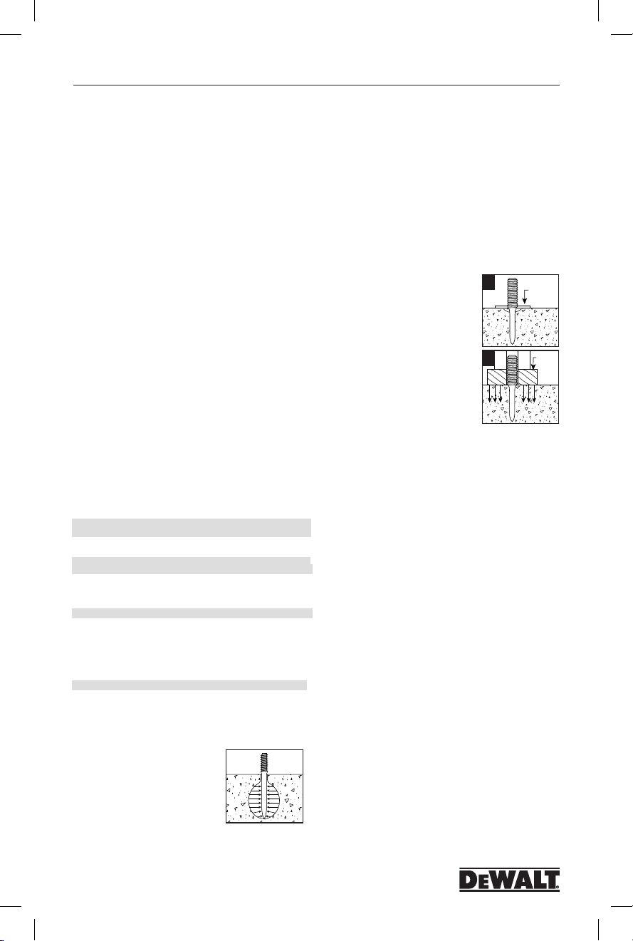
In addition to these factors, installation
tool accessories such as a stop
1
spall which reduces the tendency of
the concrete surface to spall during
the driving action can increase the
performance of the fastener.
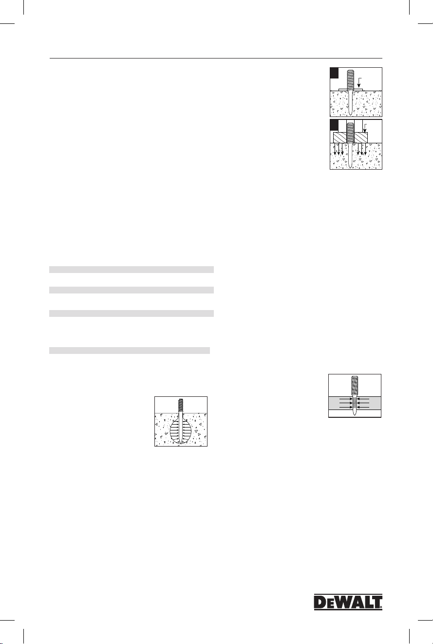
When a powder actuated fastener
is driven into concrete, it displaces the
2
volume of concrete around the embedded
area of the fastener shank. As this
occurs, the concrete directly surrounding
the fastener is compressed and in turn
presses back against the shank of the
fastener. Additionally, the driving action
generates heat which causes particles within the concrete
to fuse to the shank of the fastener. This combination of
compression and fusion holds the fastener in the concrete
base material. A similar action occurs when fastening into
block masonry.
Generally, the performance of the fastener in a given
concrete strength will increase with greater embedment
depths in a certain range. Depending on the fastener style
and base material strength, embedment depths range from
5/8” to 1-1/2”. For depths greater than this range, there is
the possibility of fastener bending or fishhooking which may
decrease expected load capacities and create a safety hazard.
During the driving action, some localized surface spalling
of the
concrete may occur. Normally, this is a surface effect which
does not effect the performance of the fastener. However,
it may pose an aesthetic problem for exposed applications
where a fixture is not used. In cases such as this, two
methods can be used to improve the appearance of the
fastening. A stop spall adapter mounted on the powder
actuated tool can help to reduce surface spalling. Another
method used is to drive the fastener through a steel washer
to improve the appearance of the application.
Functioning In Steel
The load performance of a powder
actuated fastener when installed into
steel base materials is based on the
following factors:
1. Thickness of the steel
2. Tensile strength of the steel
3. Shank diameter of the fastener
4. Depth of point penetration through the steel
5. Fastener spacing and edge distance.
When a powder actuated fastener is driven into steel, it
displaces the steel laterally 360˚ around the shank of the
fastener. Since steel is an elastic material, it presses back
against the shank of the fastener to hold it in place. As the
diameter of the fastener shank is increased, the load capacity
obtained will generally increase provided the steel thickness
is sufficient to accept the fastener. To further increase
fastener performance in steel, some fasteners have a knurled
shank which allows the steel to form a key lock into the
grooves to provide higher capacities than those obtained with
a smooth shank. For optimum performance, the fastener
point should completely penetrate the steel. Normally, a
minimum of 1/4” is allowed for the point length. An increase
in performance can be expected until the fastener no longer
completely penetrates through the steel. At this point, the
elastic properties of the steel cause a compression force to
be developed at an angle against the fastener point which
2
Washer
Stop
Spall
POW2273_manual_P2201_dewalt.indd 2 3/10/14 12:41 PM
Page 3

Model P2201 Cat. No. DDF211022P
P2201
reduces load capacity. In thicker steel base materials,
adequate load capacities may be obtained for applications in
which the point of the fastener does not fully penetrate the
steel. Job site performance tests are recommended.
Fasteners should not be used in areas that have been
welded or cut with a torch as these procedures may have
caused local hardening of the steel. Over driving of the fastener should be avoided as the rebound created may reduce
the load capacity or cause damage to the fastener. When
fastening into unsupported long steel members, it may be
necessary to provide support in the area of the fastening to
prevent spring action which can cause inconsistent penetration and a reduction in load capacity.
Suitable Base Material
While powder actuated fasteners can be used successfully in
concrete, certain masonry materials, and A 36 steel, some
materials are completely unsuitable. Fasteners should never
be fired into hard or brittle materials such as cast iron, tile,
glass, or rock. These materials can shatter easily resulting in
a potential safety hazard. In addition, soft base materials
such as wallboard, plaster, or wood are
Point
Flattens
1
not appropriate as the fastener could
pass completely through these
materials. The user should never guess
when fastening into any base material.
Failure to follow the recommended
No
Indent
Surface
Shatters
2
installation and safety guidelines can
result in severe injury or death to the
tool operator and/or bystanders.
Center Punch Test
A center punch test should always be
performed to determine the suitability
of the base material for a powder
actuated fastening. This test is relatively
Material
Cracks
simple and can help to insure a safe,
successful fastening. Be sure to wear
the appropriate eye protection when
3
performing this test. To begin, select
the fastener to be used for the job.
Then, place the point of the fastener
Fastener Sinks in
with Average
Hammer Blow
against the proposed base material.
Strike the fastener with a single
hammer blow, then examine the point.
If the point of the fastener is not blunted and the base
material has a clear point indentation, it is acceptable to
proceed with the first test installation.
Use of a powder actuated system is not recommended if
the following occurs during the center punch test:
1. The fastener point has been blunted. This indicates that the
base material is too hard.
2. The base material cracks or shatters. This indicates that
the base material is too brittle.
3. When using an average hammer blow, the fastener
penetrates the base material easily. This indicates that the
base material is too soft.
Fastener Installation Requirements
It is important to understand the required minimum base
material thickness requirements along with the minimum
spacing and edge distance requirements. Failure to follow
these requirements can result in an unsuccessful fastening
and create a safety hazard.
Base Material Thickness
Concrete base material should be at
least three (3) times as thick as the
fastener embedment penetration. If the
Penetration
concrete is too thin, the compressive
forces forming at the fasteners point can
cause the free face of the concrete to
break away. This can create a dangerous
condition from flying concrete and/
or the fastener and also results in a reduction of fastener
holding power. For applications in the face shell of concrete
masonry block, select a fastener length which will not
exceed the thickness of the face shell.
Fastener Penetration Guide
The following table lists typical embedment or penetration
depths expected in the base materials listed. The
penetration will vary depending on the density of the
material. This table should be used as a guide since the
consistency of these materials varies. When in doubt, a job
site performance test should be conducted.
DENSITY TYPICAL BASE MATERIAL PENETRATION
Soft Masonry Concrete block 1” -1-1/4”
Average Concrete Poured concrete 3/4” - 1”
Dense Concrete Pre-stressed/ 5/8” - 3/4”
pre-cast concrete
Edge Distance
Do not fasten closer than 3” from
the edge of concrete. If the concrete
cracks, the fastener may not hold.
Closer edge distances for applications
such as sill plates may be permitted
if specific fastener testing has been
conducted.
Spacing
Setting fasteners too close together
in concrete or masonry can cause
cracking. The recommended minimum
distance between fasteners is 3” center to center.
Fastener Length Selection In Concrete
For permanent applications using pins in concrete, first
determine the thickness of the fixture to be fastened. To this,
add the required embedment or penetration into the base
material. This will be the fastener shank length required.
For applications in the face shell of masonry block, select a
fastener length which will not exceed the thickness of the
face shell.
For removable applications with threaded studs, the
shank length required is equal to the embedment depth
required. To determine the minimum threaded length, add
the thickness of the fixture and the nut / washer thickness.
The nut and washer thickness is equal to the nominal thread
diameter. Do not over tighten threaded
parts. Maximum tightening torque
values are listed in the table below.
Use of a nut setter is recommended to
reduce the possibility of over tightening
the fasteners. For critical applications,
perform a job site test.
MAXIMUM TORQUE FOR 1/4” STUD MAXIMUM TORQUE FOR 3/8” STUD
(FT.-LBS.) (FT.-LBS)
2 4
Penetration
3"
3"
3x
Fixture
Embedment
3
POW2273_manual_P2201_dewalt.indd 3 3/10/14 12:41 PM
Page 4

P2201
Model P2201 Cat. No. DDF211022P
Installation In Steel
The following guidelines are based on the installation of a
fastener in ASTM A 36 structural steel with the point fully
penetrating the steel member. Recommended steel material
thickness ranges from a minimum of 1/8” to a maximum of
3/8”. For use in higher strength structural steel, applications
where the point does not penetrate the steel member, or a
thickness of steel greater than 3/8”, job site performance
tests are recommended.
Base Material Thickness
Steel base materials should be a
minimum of 1/8” in thickness.
Edge Distance
For installations in A 36 steel, 1/2”
is the recommended minimum edge
1/2"
distance.
Spacing
The recommended minimum distance
1-1/2"
Fastener Selection Guide
.300 Head Diameter Drive Pins
CAT. SHANK STD. STD. HEAD SHANK WT./
NO. LENGTH BOX CTN. DIA. DIA. 100
DDF3011000
1/2” K 100 5000 .300 .143 .5
DDF3011050
5/8” K 100 5000 .300 .143 .5
DDF3001100
3/4” 100 5000 .300 .143 .5
DDF3001150
1” 100 5000 .300 .143 .6
DDF3001200
1-1/8” 100 1000 .300 .143 .7
DDF3001250
1-1/4” 100 1000 .300 .143 .8
DDF3001300
1/8"
1-1/2” 100 1000 .300 .143 .9
DDF3001350
1-3/4” 100 1000 .300 .143 1.1
DDF3001400
2” 100 1000 .300 .143 1.2
DDF3001450
2-1/4” 100 1000 .300 .143 1.2
DDF3001500
2-3/8” 100 1000 .300 .143 1.3
DDF3001550
2-1/2” 100 1000 .300 .143 1.4
DDF3001600
2-3/4” 100 1000 .300 .143 1.6
DDF3001650
3” 100 1000 .300 .143 1.9
between fastenings is 1-1/2” center
to center for installations in ASTM A
36 steel.
Fastener Length Selection In Steel
For permanent applications when using pins in steel, first
determine the thickness of the fixture to be fastened. To this,
add the thickness of the steel base material plus a minimum
of 1/4” to allow for proper point penetration. This will be the
minimum fastener shank length required. Do not select a
fastener length longer than that required for the application.
An excessively long shank can burnish or polish the hole
created in the steel resulting in a reduction in load capacity.
For removable applications with threaded studs, the
shank length required is equal to the thickness of the steel
base material plus a minimum of 1/4” to allow for proper
point penetration. This will be the minimum fastener shank
length required. Do not select a shank length longer than
that required for the application. An excessively long shank
can burnish or polish the hole created in the steel resulting
in a reduction in load capacity. To determine the minimum
threaded length, add the thickness of the fixture and the nut
/ washer thickness. The nut and washer thickness is equal to
the nominal thread diameter.
Do not over tighten threaded studs, the maximum
tightening torque is listed in the table below. Use of a nut
setter is recommended to reduce the possibility of over
tightening the fasteners. For critical applications, perform a
job site test.
.300 Head Diameter Drive Pins with Top Hat
CAT. SHANK STD. STD. HEAD SHANK WT./
NO. LENGTH BOX CTN. DIA. DIA. 100
DDF3031000
1/2” K 100 5000 .300 .143 .5
DDF3031050
5/8” K 100 5000 .300 .143 .5
DDF3031100
3/4” 100 5000 .300 .143 .5
DDF3031150
1” 100 5000 .300 .143 .6
.300 Head Diameter Step Shank Pins
CAT. SHANK STD. STD. HEAD SHANK WT./
NO. LENGTH BOX CTN. DIA. DIA. 100
DDF3041000
3/4” Step Shank 100 1000 .300 .143/130 .5
DDF3041050
1” Step Shank 100 1000 .300 .143/130 .6
.300 Head Diameter Drive Pins - Master Pack
CAT. SHANK STD. STD. HEAD SHANK WT./
NO. LENGTH BOX CTN. DIA. DIA. 100
DDF301100M
1/2” K 1000 5000 .300 .143 .5
DDF301105M
5/8” K 1000 5000 .300 .143 .5
DDF300110M
3/4” 1000 5000 .300 .143 .5
DDF300115M
1” 1000 5000 .300 .143 .6
DDF300125M
1-1/4” 1000 5000 .300 .143 .8
DDF303100M
1/2” K TH 1000 5000 .300 .143 .5
DDF303105M
5/8” K TH 1000 5000 .300 .143 .5
DDF303110M
3/4” TH 1000 5000 .300 .143 .5
DDF303115M
1” TH 1000 5000 .300 .143 .6
.300 Head Diameter Drive Pins with 3/4” Washer
CAT. SHANK STD. STD. HEAD SHANK WT./
NO. LENGTH BOX CTN. DIA. DIA. 100
DDF3051100
3/4” 100 1000 .300 .143 1.6
DDF3051200
2-1/2” 100 1000 .300 .143 2.5
.300 Head Diameter Drive Pins with 7/8” Washer
CAT. SHANK STD. STD. HEAD SHANK WT./
NO. LENGTH BOX CTN. DIA. DIA. 100
DDF3061150
1” 100 1000 .300 .143 1.9
DDF3061250
1-1/4” 100 1000 .300 .143 2.0
DDF3061300
1-1/2” 100 1000 .300 .143 2.1
DDF3061400
2” 100 1000 .300 .143 2.4
DDF3061550
2-1/2” 100 1000 .300 .143 2.7
DDF3061650
3” 100 1000 .300 .143 3.0
.300 Head Diameter Drive Pins with 1” Washer
CAT. SHANK STD. STD. HEAD SHANK WT./
NO. LENGTH BOX CTN. DIA. DIA. 100
DDF3071000
1-1/4” 100 1000 .300 .143 2.2
DDF3071050
1-1/2” 100 1000 .300 .143 2.3
DDF3071250
2” 100 1000 .300 .143 2.6
DDF3071150
2-1/2” 100 1000 .300 .143 2.9
DDF3071200
3” 100 1000 .300 .143 3.2
4
POW2273_manual_P2201_dewalt.indd 4 3/10/14 12:41 PM
Page 5

Model P2201 Cat. No. DDF211022P
P2201
.300 Head Diameter Drive Pins with 1-7/8” Insulation Washer
CAT. SHANK STD. STD. HEAD SHANK WT./
NO. LENGTH BOX CTN. DIA. DIA. 100
DDF3081000
1-1/2” 100 1000 .300 .143 2.1
DDF3081050
2-1/2” 50 500 .300 .143 2.7
1/4”-20 Threaded Studs
CAT. THREAD SHANK STD. STD. HEAD SHANK WT./
NO. LENGTH LENGTH BOX CTN. DIA. DIA. 100
DDF3811020
1/2” 1/2”K 100 5000 1/4” .143 .8
DDF3811000
3/4” 1/2”K 100 1000 1/4” .143 1.1
DDF3811050
3/4” 3/4” 100 1000 1/4” .143 1.2
DDF3811100
1/2” 1” 100 1000 1/4” .143 1.2
DDF3811150
3/4” 1” 100 1000 1/4” .143 1.4
DDF3811180
1/2” 1-1/4” 100 1000 1/4” .143 1.4
DDF3811200
3/4” 1-1/4” 100 1000 1/4” .143 1.5
DDF3811250
1-1/4” 1-1/4” 100 1000 1/4” .143 1.7
.300 Head Diameter Pins with Ceiling Clips
CAT. SHANK STD. STD. HEAD SHANK WIRE WT./
NO. LENGTH BOX CTN. DIA. DIA. HOLE 100
DDF4111050
1” 100 1000 .300 .143 0.278” 3.5
DDF4151000
1” 100 1000 .300 .143 0.278” 3.0
DDF4111100
1-1/4” 100 1000 .300 .143 0.278” 3.7
DDF4111150
1-1/4” 100 1000 .300 .143 0.278” 3.2
.300 Head Diameter Drive Pins with
BX Cable Straps and Conduit Clips
CAT. STD. STD. HEAD SHANK WT./
NO. SHANK LENGTH BOX CTN. DIA. DIA. 100
DDF4111150
1” 100 1000 .300 .143 3.5
DDF4131050
1-1/4” 100 1000 .300 .143 3.7
DDF4121000
1/2” EMT 1” pin 100 1000 .300 .143 3.3
DDF4121050 3/4” EMT 1-1/4”pin
DDF4121100
DDF4121150
DDF4121200 1” EMT 1” pin TH
K=Knurled TH=Top Hat
.300 Head Diameter Pins with Rebar Basket Clip
CAT. STD. STD. HEAD SHANK WT./
NO. DESCRIPTION BOX CTN. DIA. DIA. 100
DDF4251000
DDF4251050
DDF4251150
DDF4252000
DDF4252500
Forming Pins
CAT. STD. STD. HEAD SHANK WT./
NO. DESCRIPTION BOX CTN. DIA. DIA. 100
DDF3951050
DDF3951000
3/4” EMT 1” pin TH
3/4” EMT 1” pin 100 1000 .300 .143 3.3
32mm w/ basket clip 100 100 8mm .143 4.0
37mm w/ basket clip 100 100 8mm .143 4.1
37mm w/ basket clip 100 100 8mm .143 4.4
37mm w/ basket clip 100 100 8mm .143 4.6
37mm w/ basket clip 100 100 8mm .143 4.8
62mm - 2-1/2” 100 1000 .205 .143 1.4
44mm - 1-5/8” 100 1000 .205 .143 1.2
Powder Load Selection Guide
CAT. POWER LOAD STD. STD. MASTER WT./
NO. LEVEL COLOR SIZE BOX CTN. CTN. 100
DDF1111100
1 Grey .22A 100 1000 20000 .33
DDF1111200
2 Brown .22A 100 1000 20000 .33
DDF1111300
3 Green .22A 100 1000 20000 .33
DDF1111400
4 Yellow .22A 100 1000 20000 .33
100 1000 .300 .143 3.5
100 500 .300 .143 3.4
25 250 .300 143 3.2
FETY INSTRUCTIONS
SAFETY INSTRUCTIONS
Safety is your primary responsibility when operating
any powder actuated tool. You must read and understand
the contents of this manual. You must be familiar with all
functional and safety requirements of the tool. It is your
responsibility to obtain proper training and a D
EWALT operator
card prior to using this tool in compliance with the current
American National Standard A10.3 Safety Requirements
for Powder Actuated Fastening Systems and the Federal
Occupational Safety and Health Administration Standards
(OSHA). Existing state or local regulations should also be
followed. When using this tool, you must have the qualified
operators card in your possession.
Revocation of card - Failure to comply with any of the rules and
regulations for safe operation of powder actuated tools shall be
cause for the immediate revocation of your qualified operator card.
Failure to following safety instructions
can result in serious injury or death to operators or
bystanders.
Prior to Operating the Tool
1. Warning signs should always be posted within the area in
which a powder actuated tool is to be used. These signs
should be at least 8” x 10” in size with boldface type that
is not less than 1” in height. The sign should state
“Powder Actuated Tool In Use”.
2. Approved eye protection should always be worn by operator or bystander, to protect their eyes from flying particles.
Hearing protection should always be worn by the operator
and bystanders when using a powder actuated tool. Other
personal safety protection as required should also be used.
3. Never modify or fabricate parts for use in your D
tool. Use only D
EWALT fasteners, loads, and tool parts.
4. Hands or other body parts must never be placed in front
of muzzle/barrel. Accidental discharge can cause piston
and/or fastener to pass through the operator’s hand.
5. Never compress the tool against any part of the body.
Serious injury or death may result in the event of an
accidental discharge.
6. Always point tool in a safe direction at all times.
Intended Purpose
7. Keep all other people, especially children, away from the
work area.
8. Use only in a well-lit, well-ventilated work area.
Preparation for Loading the Tool
1. Tools must be checked prior to operating to make sure
they are not fully or partially loaded with a powder load or
fastener.
2. To insure safe operation, perform the daily function test
described in this manual. Be sure the tool is not loaded
prior to performing this test.
3. Do not operate this tool unless all its parts are in place
and operating appropriately. Never attempt to use a
malfunctioning tool. Call 1-800-4-DEWALT for assistance.
4. Never guess about the suitability of a base material. If
you are uncertain about the suitability of a base material,
perform a center punch test.
5. Do not operate the tool until you learn and understand the
color code / numbering system used to identify the power
level of powder loads.
Operating the Tool
1. Only use fasteners and powder loads designed for this
tool as supplied by D
EWALT.
2. Do not use powder actuated tools in the presence of
flammable fumes or vapor or an explosive atmosphere.
3. Do not fire a tool without a fastener. The piston will
EWALT
5
POW2273_manual_P2201_dewalt.indd 5 3/10/14 12:41 PM
Page 6
P2201
Model P2201 Cat. No. DDF211022P
R2200
impact the work surface possibly causing serious injury to
the operator or bystanders along with damage to the tool.
4. Do not load the tool until you are ready to make a
fastening. Check the power load level before inserting it into
the tool chamber.
5. Fastener must be loaded prior to loading the powder load,
to prevent injury to operator or bystander in the event of
an accidental discharge.
6. Do not close tool against work surface. The tool should be
manually closed, with hand away from muzzle/barrel to
prevent accidental discharge.
7. Hold the tool perpendicular to the work surface at all
times. Use a spall guard (part # 52166) wherever possible.
This will limit the possibility of fastener ricochet which
could cause serious injury or death to the operator or
bystanders. To order optional spall guard at no charge call
1-800-4-DEWALT.
8. Always perform a test fastening with the lightest load level
designed for use in the tool. If the lightest load fails to set
the fastener, try the next highest load until the proper level
is attained. Failure to follow this procedure may cause the
fastener to be overpowered. If this occurs, the fastener
may fully penetrate the base material causing serious
injury or death to someone. Overpowering the fastener can
also damage the tool, creating a safety hazard to both the
operator or bystanders.
9. Do not fasten into cast iron, tile, glass, or other types of
brittle materials. These materials can shatter and create
sharp fragments which may cause injury.
10. Do not fire tool within 3” (three inches) of the edge of a
concrete base material or within 1/2” (one-half inch) of
the edge of a steel base material.
11. Do not attempt to install a fastener closer than 3” (three
inches) to another previously inserted fastener in concrete
or 1-1/2” (one and one-half inch) in steel.
12. Do not fasten into a concrete base material less than 3
times as thick as the fastener penetration or into a steel
base material thinner than 1/8”.
13. Never attempt to install a fastener in a cracked or spalled
area in concrete. Place fastener at least 3” (three inches)
away from a spalled area to prevent the possibility of the
fastener bending and striking an operator or bystander.
14. Do not attempt to install fasteners in areas that have been
welded or cut with a torch as these procedures may have
caused local hardening of the steel.
15. Do not fasten through a pre-drilled hole unless proper
guidance is provided.
16. If you decide not to make a fastening after the tool has
been loaded, you must always remove the powder load first
followed by the fastener.
17. Never attempt to override the safety features of this tool.
18. Stay Alert, watch what you are doing, and use common
sense. Do not use tool when you are tired or under the
influence of drugs or alcohol.
19.Maintain proper footing and balance. Do not over reach.
20. Check that no one is present directly behind or below the
work surface.
Handling the Tool And Powder Loads
1. Never leave a loaded tool unattended. Once the tool is
loaded, make the fastening immediately or unload the tool.
2. Always unload the tool before work breaks, changing parts,
cleaning or servicing, and when storing.
3. To prevent accidental discharge of loads, never carry the
powder loads in the same container as the fasteners or
other hard objects.
4. Always store the powder loads in the containers provided
or in an enclosure provided for them. Never intermix the
various power levels. Keep them segregated in clearly
identified containers.
5.
Powder loads should never be used in firearms. They are normally
more powerful that the cartridges supplied with the firearms.
6.
Powder actuated tools and powder loads should always be stored
under lock and key. Tools must be unloaded when not in use.
Tool Malfunction
1. In the event that a load fails to discharge after the trigger
is pulled, the tool must be kept depressed against the
work surface for a minimum of 30 (thirty) seconds in case
of a delayed load discharge. Then carefully remove the
entire load strip. and dispose of it in a can of water or
other nonflammable liquid. Never attempt to force or pry a
load out of a tool chamber.
2. Never discard unfired powder loads into a trash container.
3. Do not attempt to unload or disassemble a jammed,
stuck or broken tool as improper handling may cause
it to discharge and strike operator and/or bystander. A
jammed tool must be pointed in a safe direction at all
times. Tag the tool and lock it up. Call your D
representative for proper assistance.
Tool Operation
the safety precautions and training in this manual before
attempting to operate the tool. (Check to be sure the tool is
not loaded, the piston moves freely within the barrel, and no
foreign objects or fasteners are in the barrel.) Perform the
daily function test before using the tool.
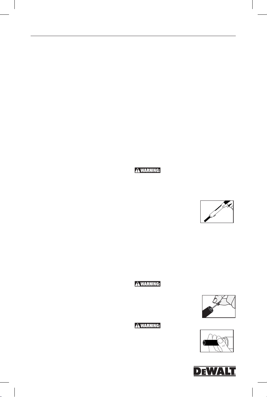
Operation
1. Always point the tool in a safe
direction away from bystanders
and the operator. Slide the barrel
forward. This can be done by
snapping your wrist. The barrel should be pulled fully
forward to reset the piston for the next fastening. Loss of
power may result from an im properly positioned piston.
2. Always load the fastener before inserting powder load to
prevent injury to the operator or bystanders in the event of
an accidental discharge. Place the fastener, point out, into
the end of the nose piece until the fluted tip fits inside.
Do not use excessive force when inserting the fastener. If
excessive force is required, stop and determine why the
fastener can not be inserted. Correct the problem before
proceeding.
listed in the fastener selection section of this manual.
3. Make sure the breech is clear. Insert
the powder load starting with the
lowest power level. If this Load does
not fully set the fastener, try the next
higher power level until the proper
level is found.
cause a safety hazard.
4. Pull the barrel all the way back to
close the tool. Do not attempt to
close the tool by exerting force on
the front of the nose piece. Never
place your fingers or hands over
muzzle bushing. The safe position for hands and fingers
Be sure to read and understand all of
Do not use fasteners longer than 3” as
Over driving or over powering a fastener can
6
EWALT
POW2273_manual_P2201_dewalt.indd 6 3/10/14 12:41 PM
Page 7

Model P2201 Cat. No. DDF211022P
P2201
are as shown in the diagram. Hands must never be
placed in front of the tool muzzle or nose piece. In the
event of an accidental discharge, the piston and/or
fastener can pass through the operators hand.
5. Once the tool is in the closed
position, place it against the work
surface. Hold the tool firmly with
two hands and completely depress
the barrel. Then squeeze the
trigger. Always hold the tool perpendicular to the work
surface. Hold the tool firmly against the work surface to
avoid excessive recoil. Never depress the tool against
anything except the work surface.
In the event that the load does not discharge
after the trigger is pulled, continue to hold the tool depressed
against the work surface for at least 30 (thirty) seconds in
case of a delayed load discharge. Then carefully remove the
entire load strip and dispose of it in a can of water or other
non flammable liquid. Never attempt to force or pry a load
out of a tool chamber. Do not discard unfired loads into a
trash container.
6. To prepare for the next fastening, point the tool in a safe
direction. Snap the barrel forward as described in step 1.
This action will eject the spent powder load and properly
reset the piston. Always insert a new fastener before
loading powder load in the chamber. Do not attempt to
unload or disassemble a jammed, stuck or broken tool
as improper handling may cause it to discharge and
strike operator and/or bystander. A jammed tool must be
pointed in a safe direction at all times. Tag the tool and
lock it up. Call your D
proper assistance.
EWALT Fasteners representative for
Maintenance & Cleaning
MAKE SURE THE TOOL IS NOT LOADED.
BE SURE THE TOOL IS NOT HOT PRIOR TO ATTEMPTING
DISASSEMBLY OR CLEANING.
Daily Function Test
Check the functioning of the tool, without a powder load
or fastener in the tool, by pushing down against the work
surface, pulling the trigger, and releasing the tool from the
work surface. Function the unloaded tool several times and
insure that the breech parts and firing mechanism operate
freely before fastening with the tool.
Your D
EWALT Authorized representative should be asked
to assist the first time you disassemble and clean your tool.
If you ever have any trouble reassembling the tool, or have
any doubt about worn parts, call your D
Powder Distributor.
Cleaning
AIl parts should be cleaned with detergent oil and the wire
brushes supplied with your tool kit. Remove heavy dirt buildup with the brush. After cleaning with oil, all parts should be
wiped thoroughly dry. Excess oil will tend to collect dirt and
dust. Wear eye protection when cleaning the tool. The piston
rod, barrel assembly, and receiver should all be cleaned of
excess dirt on a daily basis. Check the condition of the piston
for damage from wear and deformation.
To maintain this tool in good working condition, it is
necessary to disas semble and clean the entire tool if dirt
EWALT Authorized
is evident in the breech face, or if the tool appears to lose
power. All parts should be cleaned with oil and wire brushes.
Remove heavy dirt. All parts should be wiped thoroughly dry
after cleaning with oil.
General tool mainte nance should be performed at six
month intervals or more frequently as required by the
frequency of tool use.
Replacing or Repairing the Piston
The piston is an expendable part and must be replaced
periodically. Typical signs of a worn out piston are: breaking,
bending or mushrooming. Prior to
servicing the tool make sure there is no
powder load in the tool. Use caution and
do not lose or damage any tool parts.
1. Loosen the cap on the reset pin by
turning it counter clockwise. Remove the
reset pin cap.
2. Hold the barrel in place, then remove
the reset pin spring and reset pin.
3. Slide the barrel from the receiver by
pulling it forward. If excessive dirt is built
up inside the receiver, clean it with a wire
brush.
4. Unthread the nose piece from the
barrel by turning it counter clockwise.
Pull the piston forward out of the barrel.
If a vise clamp is used
to hold the barrel, protect the bar rel from
damage.
5. Clean the piston using a wire brush.
Inspect it for worn or damaged piston ring,
chipped end, or bending. Apply lubricant to
the piston shank to minimize piston sticking
from an overdrive con dition. Wipe the piston
dry.
6. If a piston tip is damaged, it can be
shortened a maximum of 0.20 inches.
The tip of the piston should be grooved
flat and at 90 degrees to the shank of
the piston. The cham fer of the piston
must also be reground as shown. Piston
grinding should be performed by qualified per sonnel using
the proper equipment.
Reassembly:
7. Press the piston into the barrel.
Thread the nose piece into the barrel
and tighten it clockwise until finger tight.
Be sure the nose piece is fully seated.
8. Align the slot in the barrel with the
reset pin opening in the bottom of
the receiver. Insert the barrel into the
receiver. Insert the reset pin, and reset
pin spring. Tighten the reset pin cap
clockwise until it is finger tight and fully seated.
Upon reassembly of the tool perform the following test.
Depress the tool against a flat, hard surface and pull the
trigger. The barrel assembly should slide smoothly inside the
tool receiver. The firing pin should release after the trigger has
been pulled.
1
2
3
4
5
6
7
8
THIS TEST SHOULD BE PERFORMED
WITHOUT A PIN OR POWDER LOAD IN THE TOOL.
10°
0.120"
7
POW2273_manual_P2201_dewalt.indd 7 3/10/14 12:41 PM
Page 8

P2201
Model P2201 Cat. No. DDF211022P
#
Troubleshooting
ALWAYS CHECK INSTRUCTION MANUAL FOR PROPER ASSEMBLY OF PARTS
PROBLEM POSSIBLE CAUSE SOLUTION
Fastener Overdriving Power level too high / Pin too short Use a lower powder load level number or a longer pin
Tool does not fire Tool not depressed completely See “Tool does not depress completely” section below
Tool does not depress completely Damaged firing pin parts, ejector, etc. Parts
Power reduction or inconsistent
fastener penetra tion
Load strip cannot be
inserted into tool
Load strip will not advance Worn advance lever guide Replace advance lever guide. This should be performed
Load will not fire when
trigger is pulled
Load will not fire when tool is fully
depressed and trigger is pulled
Tool cannot be opened
or cycled
Piston stuck in the forward
position
Chipped or damaged piston Tool not held on work surface squarely.
Piston guide will not open easily Bent shear clip Remove and replace shear clip
Piston guide opens too easily Annular ball spring or steel annular ball
Soft base material Check base material suitability section
Firing pin damaged Replace damaged part(s)
assembled improperly
Barrel is not pulled fully forward when
cycling tool.
Worn or damaged piston Replace piston or piston ring
Improper loading Insert strip from the bottom of the tool handle
Wrong caliber strip Use proper strip
Tool is not fully depressed Follow safety procedure for misfired load then attempt to
Load is already fired Cycle tool
Load misfire Follow safety procedure
Broken firing pin Replace firing pin nut. This should be performed by
Broken or missing Replace firing pin nut. This firing pin nut should be
Lack of proper cleaning Clean tool thoroughly
Damaged or bent piston Remove and replace piston
Broken or damaged parts Tag tool with warning “Defective - Do Not Use” place in
Piston has been overdriven and is jammed
against piston reset pin
This allows the piston to slip off the head of
the pin and cause damage to the piston
Excessive build-up of dirt Disassemble and clean tool
Piston stop is damaged Replace piston stop
Foreign material jammed between the
piston guide and steel liner assembly
have worn
Check the parts for damage or improper assembly
Barrel must be pulled out completely to properly reset
the piston
by qualified individuals
fully depress tool before pulling trigger
qualified individuals
locked container and contact your D
representative for service
Tap the piston against a hard surface
Machine piston as shown on page 11. Piston regrinding
may be performed only by
qualified individuals
Disassemble and remove foreign particles
Remove and replace with a new spring and/or ball
EWALT Authorized
8
POW2273_manual_P2201_dewalt.indd 8 3/10/14 12:41 PM
Page 9

Model P2201 Cat. No. DDF211022P
P2201
COMPANY NAME
COMPANY PHONE
QUALIFIED TOOL OPERATOR EXAMINATION
#
OPERATOR’S NAME
HOME ADDRESS
AGE DATE OF BIRTH
3
☐
Check the correct answer
1 It is necessary to read the Operator’s Manual prior
to operating a D
☐
2 When fastening into concrete, the base material
should be greater than the shank penetration by at
least:
3 When operating a powder actuated tool, your hand
should never be placed:
☐
☐
☐
4 To determine the suitability of a base material, use
the fastener as a center punch.
• Ifthefastenerisblunted,donotfasten;thematerial
is too:
☐
• Ifthefastenerpenetrateseasily,donotfasten;the
material is too:
☐
• Ifthematerialcracksorshatters,donotfasten;the
material is too:
☐
5 Unsafe applications for powder actuated tools may
be caused by which of the following?
☐
☐
☐
☐
☐
☐
☐
6 Which one of the following building materials is not
suitable as a receiving material (base material) for
powder actuated fasteners?
☐
☐
EWALT low velocity tool.
True ☐ False
☐
1 time ☐2 times ☐3 times
around the tool body
in front of the tool muzzle
over the tool handle
soft
☐
hard ☐brittle
soft ☐hard ☐brittle
soft ☐hard ☐brittle
a soft base material
improper powder load
fastening too close to an unsupported edge
a malfunctioning tool
fastening into a spalled area
fastening through a pre-existing hole
all of the above
sheet rock ☐ wood ☐fiberglass
sheet metal ☐all of the above
7 When considering the safety of a particular
application, the operator must think about:
☐
the base material
☐
the powder load power level
☐
the operator’s safety
☐
the safety of bystanders and fellow workers
☐
all of the above
8 The proper loading procedure is: insert fastener first,
powder load second. The fastener should always be
placed in the tool prior to the load.
☐
True ☐False
9 Which one of the following materials is usually
suitable for powder actuated fastenings?
☐
poured concrete ☐hollow tile
☐
surface hardened steel ☐glazed brick
10 In concrete, a fastener should be driven no closer to
an unsupported edge than:
☐
1/2” ☐1-1/2” ☐3”
11 Fishhooking is a condition which can occur when
a powder actuated fastener strikes a piece of hard
aggregate or very hard concrete, bends and comes
out of the work surface. A fishhook can cause a
serious injury or death.
☐
True ☐False
12 Placing a hand over the muzzle bushing of a
loaded tool can result in serious injury from piston
overdrive or an escaping fastener if the tool is
discharged accidentally.
☐
True ☐False
13 Piston overdrive is caused by overpowering of
the tool or by discharging the tool against a soft
surface.
☐
True ☐False
14 Malfunctioning tools cannot be used and must be
removed from service immediately.
☐
True ☐False
COMPANY ADDRESS
SIGNATURE DATE
15 After conducting a Center Punch Test,the best
way to check the base material is to set several
fasteners using the least powerful load.
☐
True ☐False False
16 Eye protection and hearing protection should not be
worn by the operator and any necessary bystanders
when using the tool.
☐
True ☐False
17 A powder actuated tool cannot be safely used in an
explosive or flammable atmosphere.
☐
True ☐False
18 List the proper powder load level number
(1-6) next to each color listed.
Red ___ Brown ___ Green ___
Yellow ___ Gray ___ Purple ___
19 The weakest power level should be used when
making the first fastening.
☐
True ☐False
20 You can fasten into welded areas of steel.
☐
True ☐False
P2201
• Theproperprocedureifapowderloadfailstoignite
is to hold the tool against the work surface and wait
30 seconds, then proceed exactly as directed in the
Operator’s Manual.
☐
True ☐False
• D
EWALT powder loads for the P2100 are .22
caliber, “A” tapered, neck down, rim fire, short
crimped cartridges. No other powder load may be
used in this tool.
• OperatorsshouldnevercompresstheP2201orany
other powder actuated tool against any part of their
body.
• IfapistonbufferfortheP2201becomesdeformed,
simply remove it, and use the tool without the
buffer?
☐
True ☐False
☐
True ☐False
☐
True ☐False
LICENSE AND WARRANTY ACTIVATION
THE P2201 TOOL IS WARRANTED FOR 3 YEARS FROM DATE OF PURCHASE ON MANUFACTURERS DEFECTS.
I certify that I have read and understand the P2201 Tool Operating Instruction Manual and have taken the Operator’s exam. I understand the
TRIM ALONG DOTTED LINE, PLACE IN ENVELOPE, ADDRESS AS SHOWN AND AFFIX POSTAGE
importance of following all safety procedures and that failure to read, comprehend, and follow the detailed rules and warnings regarding the
safe operation of powder actuated tools can result in serious injury or death to the tool operator or bystanders. I agree to conform to all the
rules and regulations regarding the use of powder actuated tools.
THE SERIAL NUMBER ON MY TOOL IS:
PLEASE SEND MY TOOL LICENSE TO:
NAME
ADDRESS
CITY STATE ZIP PHONE
(Please print clearly)
MAIL TO: Tool License Coordinator • D
EWALT, Inc.• 2 Powers Lane, Brewster, NY 10509
9
POW2273_manual_P2201_dewalt.indd 9 3/10/14 12:41 PM
Page 10
P2201
Modelo P2201 N.˚ de Cat. DDF211022P
R2200
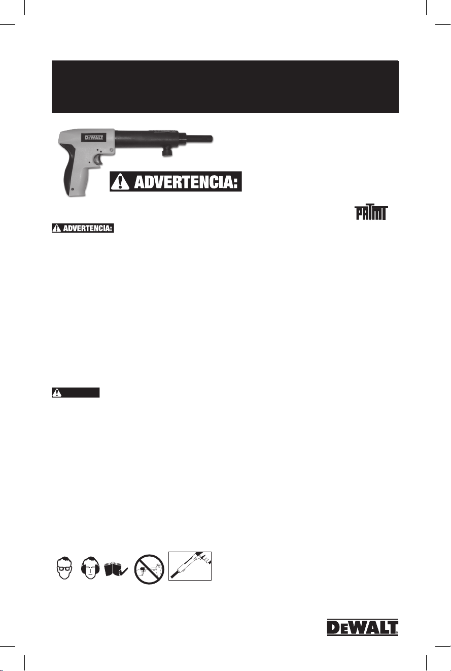
P2201
MANUAL DE INSTRUCCIONES
PARA OPERAR LA HERRAMIENTA
Herramienta de sujeción
accionada por pólvora de
baja velocidad
DO NOT OPERATE THE P2201
TOOL UNTIL YOU HAVE READ THIS MANUAL AND RECEIVED THE
PROPER TRAINING ACCORDING TO ANSI STANDARD A 10.3-1995.
P3500, LEA ATENTAMENTE ESTE MANUAL Y ASEGÚRESE DE
ENTENDER COMPLETAMENTE EL CONTENIDO.
DEBE RECIBIR UNA CAPACITACIÓN ADECUADA SEGÚN LO INDICA
LA NORMA A 10.3 VIGENTE DE ANSI, RESPETAR LOS REQUISITOS
DE SEGURIDAD PARA LOS SISTEMAS DE SUJECIÓN ACCIONADOS
POR PÓLVORA Y OBTENER LA TARJETA DE OPERADOR CALIFICADO
DE DEWALT ANTES DE OPERAR LA HERRAMIENTA. TAMBIÉN DEBE
CUMPLIR CON LAS REGULACIONES ESTATALES, LOCALES, ENTRE
OTRAS. ES POSIBLE QUE LAS LEYES, REGULACIONES Y NORMAS
RESPECTO DEL USO DE LAS HERRAMIENTAS ACCIONADAS POR
PÓLVORA SE REVISEN PERIÓDICAMENTE. CUALQUIER REVISIÓN
PUEDE MODIFICAR LOS PROCEDIMIENTOS DE SEGURIDAD Y
OPERACIÓN DESCRITOS EN ESTE MANUAL. D
SE HACE RESPONSABLE DE NINGUNA REVISIÓN POSTERIOR A
LA PUBLICACIÓN DE ESTE MANUAL. ES RESPONSABILIDAD DEL
USUARIO MANTENERSE ACTUALIZADO RESPECTO DE LAS LEYES,
REGULACIONES Y NORMAS VIGENTES QUE SE APLIQUEN A LA
HERRAMIENTA ACCIONADA POR PÓLVORA.
PELIGRO:
E INCLUSO LA MUERTE: NUNCA CIERRE LA HERRAMIENTA
COLOCANDO ALGUNA PARTE DE LA MANO SOBRE EL EXTREMO
DE LA BOCA DEL CAÑÓN.
LOS OPERADORES Y DEMÁS PERSONAS QUE SE ENCUENTREN EN
EL LUGAR DEBEN UTILIZAR PROTECCIÓN OCULAR Y AUDITIVA.
SIEMPRE ASUMA QUE LA HERRAMIENTA ESTÁ CARGADA. NO
COLOQUE LOS DEDOS EN EL GATILLO DE LA HERRAMIENTA
CARGADA HASTA QUE EL EXTREMO DE LA BOCA DEL CAÑÓN
ESTÉ CONTRA LA SUPERFICIE DE TRABAJO Y USTED ESTÉ LISTO
PARA REALIZAR UNA SUJECIÓN. NUNCA COLOQUE LA MANO
SOBRE LA BOCA DEL CAÑÓN CON UNA CARGA DE PÓLVORA
EN LA HERRAMIENTA. SI LA HERRAMIENTA SE DISPARA
ACCIDENTALMENTE, EL PISTÓN O SUJETADOR PUEDE PENETRAR
EN LA MANO Y OCASIONAR LESIONES GRAVES.
OPERACIÓN DE LA HERRAMIENTA DEBE LEER Y COMPRENDER EL
MANUAL DE LA HERRAMIENTA Y DEBE COMPLETAR EXAMEN DEL
OPERADOR EN LA ÚLTIMA PÁGINA. LA HERRAMIENTA GARANTÍA
NO SERÁ VÁLIDA HASTA QUE SE RECIBA LA PRUEBA, CON UNA
COPIA DE SU RECIBO, Y REVISADO POR D
ANTES DE OPERAR LA HERRAMIENTA
EWALT, INC. NO
A FIN DE EVITAR LESIONES GRAVES
EWALT, INC.
R2200
Garantía
Tres años de garantía limitada
D
EWALT reparará, sin cargo, cualquier defecto ocasionado
por materiales defectuosos o mano de obra durante
tres años a partir de la fecha de compra. Esta garantía
no cubre fallas de las piezas causadas por su desgaste
normal o abuso a la herramienta. Para mayores detalles
sobre la cobertura de la garantía e información de
reparación en garantía, visite www.dewalt.com o llame al
1-800-4-DEWALT (1-800-433-9258). Esta garantía no
aplica a accesorios oa daños causados se han hecho o
intentado hacer reparaciones por otros. Esta garantía le
otorga derechos legales específicos cualquiera puede tener
otros derechos que varían de estado a estado.
Además de la garantía, las herramientas DEWALT están cubiertas por:
D
EWALT mantendrá la herramienta y reemplazará las
piezas gastadas por su uso normal, sin cobro, en cualquier
momento durante el primer año después de la compra.
Si usted no está completamente satisfecho con el desempeño
de su máquina herramienta accionadas por pólvora D
por cualquier motivo, puede devolverla dentro de los 90 días
a partir de la fecha de compra con su recibo y obtener el
reembolso completo - sin hacer preguntas.
ETIQUETAS DE ADVERTENCIA GRATUITO DE REEMPLAZO:
Si sus etiquetas de advertencia se vuelven ilegibles o se
pierden, llame al 1-800-4-DEWALT (1-800-433-9258) para
obtener un reemplazo gratis.
1 AÑO DE SERVICIO GRATUITO
90 DíAS GARANTíA DE REEMBOLSO
Introducción
Gracias por comprar la herramienta accionada DEWALT
P2201 polvo de baja velocidad de usted. Esta herramienta
le ofrecerá un excelente rendimiento siempre que se sigan
los pasos para la operación y el mantenimiento adecuado.
Sistemas de fijación accionadas por pólvora pueden
proporcionar un método rentable de adjuntar accesorios para
trabajo liviano, condiciones de carga estática. Los sistemas
proporcionados por D
de fijación especialmente diseñados, herramientas de
instalación, y cargas de pólvora que están diseñados para
funcionar en combinación para proporcionar un rendimiento
óptimo. Mientras que las herramientas accionadas por
pólvora pueden proporcionar uno de los medios más rápidos
y económicos de la atadura, sino que también pueden ser
peligrosos si no se operan correctamente.
EWALT consisten de elementos
™
EWALT
10
POW2273_manual_P2201_dewalt.indd 10 3/10/14 12:41 PM
Page 11
Modelo P2201 N.˚ de Cat. DDF211022P
P2201
Antes de operar la herramienta P2201, debe estar
Stop
Spall
debidamente capacitado en la operación y mantenimiento de
esta herramienta y emitirá una Tarjeta Operador Calificado
D
EWALT. Al utilizar la herramienta, debe tener esta tarjeta
en su posesión. Como parte del proceso de formación,
debe leer y comprender el contenido de este manual de
instrucciones en especial las medidas de seguridad.
Herramientas accionadas por pólvora solamente debe
ser utilizado por los operadores debidamente capacitados
como se describe en la norma ANSI A 10.3, Requisitos de
seguridad para Polvo Sistemas de sujetadores accionados.
Para detalles completos de la operación de la herramienta,
póngase en contacto con su oficina sucursal DEWALT o
distribuidor local para la formación.
Recuerde, la seguridad comienza con usted! Es su
responsabilidad principal cuando utilice esta herramienta.
Si no se siguen los procedimientos de operación,
mantenimiento y seguridad adecuadas, pueden producirse
lesiones graves o la muerte a usted oa otras personas.
Además de la formación impartida, usted debe estar
familiarizado con cualquier, estatales y federales locales.
Si usted tiene alguna pregunta que no se incluyen en
este manual, póngase en contacto con su oficina sucursal
D
EWALT o distribuidor local.
Size Range
Longitudesdelpasadorde1/2”a3”;calibre0,22
Tool Description
La P2201 es una velocidad baja, un solo disparo, calibre .22
herramienta que puede utilizarse para instalar pasadores de
arrastre 0.300 la cabeza, pasadores de arrastre con cabeza
de 8 mm y 1/4 “-20 espárragos roscados, de hasta 3” de
longitud total. El P2201 está diseñado para el mantenimiento
o contratistas residenciales.
DATOS TÉCNICOS
CUERPO DE LA LONGITUD LONGITUD DE LA
HERRAMIENTA DEL PASADOR HERRAMIENTA
plástico de ingeniería 1/2 “a 3” Longitud total 12-1/2”
TIPO DE CARGA PESO DE LA NIVEL DE
HERRAMIENTA POTENCIA
Calibre 0,22 en 4,3 libras. Gris (1), Marrón (2),
Crimped “A” Load
TIPO DE PASADOR
Pasador de arrastre Ballistic Point, pasador de arrastre con cabeza
de 0,300”, pasador de arrastre con cabeza de 8 mm, espárrago roscado
de 1/4”-20
Verde (3), Amarillo (4)
P2201 Selection Guide
CAT NO. DESCRIPTION STD CTN.
DFC211022D P2201 Tool (Blister Pack) 1
52522 Piston 1
52510 Nose Piece 1
52512 Piston Reset Pin 1
Funcionamiento del sujetador
Antes de aprender los procedimientos
seguros de operación para esta
herramienta, es importante entender
cómo funciona un sujetador accionado
en el material de base. La acción de conducción provoca
tremendas fuerzas que han de aplicarse al elemento de
sujeción. Sujetadores accionados polvo DEWALT están
especialmente diseñados y fabricados utilizando un proceso
austempering para soportar las fuerzas impuestas durante
la operación de conducción. Sólo los elementos de fijación
fabricados o suministrados por DEWALT deben ser utilizados
en esta herramienta.
Funcionamiento En Concreto
El rendimiento de un elemento de fijación accionado en polvo
cuando se instala en los materiales de base de hormigón o
mampostería se basa en los siguientes factores:
1. Fuerza del material de base
2. La dureza y la concentración del agregado
3. Diámetro del vástago del elemento de
fijación
4. Profundidad de empotramiento en el
1
material de base
5. Espaciamiento de sujetadores y
distancia al borde
Además de estos factores, accesorios
de la herramienta de instalación como por
ejemplo un esquirlas parada que reduce
2
la tendencia de la superficie de hormigón
a astillarse durante la acción de conducir
pueden aumentar el rendimiento del
elemento de fijación.
Cuando un elemento de fijación
accionado en polvo es impulsado en el hormigón, que
desplaza el volumen de hormigón alrededor de la zona
incrustada del vástago del sujetador. Mientras esto ocurre,
el hormigón que rodea directamente el elemento de fijación
es comprimido y, a su vez presiona contra el vástago del
sujetador. Además, la acción de conducción genera calor
que hace que las partículas dentro del hormigón se fusionen
al vástago del elemento de fijación. Esta combinación de
compresión y de fusión mantiene el elemento de fijación en el
material de base de hormigón. Una acción similar se produce
cuando la fijación en el bloque de mampostería.
En general, el rendimiento del elemento de fijación en
una determinada resistencia del hormigón aumentará con
mayores profundidades de empotramiento en un cierto rango.
Dependiendo del estilo de sujetador y la resistencia del
material base, profundidades de empotramiento van desde
5/8 “a 1-1/2”. Para profundidades superiores a este rango,
existe la posibilidad de flexión sujetador o fishhooking que
puede disminuir la capacidad de carga esperadas y crear un
peligro de seguridad.
Durante la acción de conducir, se puede producir algún
desprendimiento localizada en la superficie del hormigón.
Normalmente, este es un efecto de superficie que no afecta el
rendimiento del elemento de fijación. Sin embargo, se puede
plantear un problema estético para aplicaciones expuestas
en los que no se utiliza un accesorio. En casos como este,
dos métodos se pueden utilizar para mejorar la apariencia
de la fijación. Un adaptador de parada spall montado en la
herramienta accionada por pólvora puede ayudar a reducir el
desconchado de la superficie. Otro método utilizado es para
accionar el sujetador a través de una arandela de acero para
mejorar la apariencia de la aplicación.
por pólvora. Un elemento de fijación
accionado en polvo se considera que
es un accionamiento directo o tipo de entrada forzada de
elemento de fijación, ya que es impulsado directamente
Washer
Stop
Spall
11
POW2273_manual_P2201_dewalt.indd 11 3/10/14 12:41 PM
Page 12

P2201
Modelo P2201 N.˚ de Cat. DDF211022P
Funcionamiento En Acero
El rendimiento de la carga de un
sujetador accionado polvo cuando se
instala en materiales base de acero se
basa en los siguientes factores:
1. Espesor del acero
2. Resistencia a la tracción del acero
3. Diámetro del vástago del elemento de fijación
4. La profundidad del punto de penetración a través del acero
5. Espaciamiento de sujetadores y distancia al borde.
Cuando un elemento de fijación accionado en polvo es
impulsado en acero , que desplaza el acero lateralmente
360 ˚ alrededor del vástago del elemento de fijación .
Dado que el acero es un material elástico , que presiona
hacia atrás contra el vástago del elemento de fijación para
mantenerlo en su lugar . A medida que aumenta el diámetro
del vástago del sujetador , la capacidad de carga obtenido
generalmente aumentará siempre que el espesor del acero
es suficiente para aceptar el elemento de fijación . Para
aumentar aún más el rendimiento de fijación de acero ,
algunos elementos de fijación tienen un vástago moleteado
que permite que el acero para formar un bloqueo de llave
en los surcos para proporcionar capacidades más altos que
los obtenidos con un vástago liso . Para un rendimiento
óptimo , el punto de fijación debe penetrar completamente
el acero . Normalmente , se permite un mínimo de 1/ 4 “
para la longitud de punto . Un aumento en el rendimiento
se puede esperar hasta que el elemento de fijación ya no
penetra completamente a través del acero . En este punto
, las propiedades elásticas del acero causan una fuerza
de compresión a ser desarrollado en un ángulo contra el
punto de sujeción que reduce la capacidad de carga . En
materiales de base de acero más gruesas , capacidades de
carga adecuados se pueden obtener para aplicaciones en las
que el punto del elemento de sujeción no penetra totalmente
el acero . Se recomiendan las pruebas de rendimiento del
sitio de trabajo .
soldadas o cortadas con una antorcha ya que estos
procedimientos pueden haber causado el endurecimiento
local de la de acero. Durante la conducción del elemento
de fijación se debe evitar el rebote creado puede reducir
la capacidad de carga o causar daños al elemento de
sujeción. Cuando la fijación en miembros de acero largos no
compatibles, puede ser necesario para proporcionar soporte
en la zona de la fijación para evitar la acción del resorte que
puede causar la penetración inconsistente y una reducción
en la capacidad de carga.
Centro de pruebas de perforación
Una prueba de punzón siempre se debe realizar para
determinar la idoneidad del material de base para fijar por
este medio. Esta prueba es relativamente simple y puede
ayudar a asegurar una, de fijación seguro y exitoso.
Asegúrese de usar la protección adecuada para los ojos
cuando se realiza esta prueba. Para comenzar, selecciona el
dispositivo de fijación que se utilizará para el trabajo. A
continuación, coloque el punto de la fijación contra el
material de base propuesta. Golpee el elemento con un solo
golpe de martillo, a continuación, examinar la cuestión. Si el
punto del elemento de fijación
no está embotado y el material de
1
base tiene un punto de indentación
claro, es aceptable para proceder con
la primera instalación de prueba.
El uso de un sistema de
accionamiento de polvo, no se
recomienda si ocurre lo siguiente
durante la prueba de punzón:
1. El punto de fijación se ha mitigado.
2
Esto indica que el material de base
es demasiado duro.
2. Las grietas del material base o se
rompe. Esto indica que el material
de base es demasiado frágil.
3. Cuando se utiliza un golpe promedio
de martillo, el sujetador penetra en
el material base con facilidad. Esto
3
indica que el material de base es
demasiado suave.
Fastener Sinks in
with Average
Hammer Blow
Requisitos de instalación de fijaciones
Es importante entender los requisitos de espesor de material
de base mínimos requeridos, junto con la separación mínima
y requisitos de distancia del borde. El incumplimiento de estos
requisitos puede dar lugar a una fijación sin éxito y crear
un peligro de seguridad.
Base Material Espesor
Material de base de concreto debe
ser por lo menos tres (3) veces
más grueso que la penetración
Penetration
de empotramiento sujetador. Si el
concreto es muy delgada, las fuerzas
de compresión que forman en el
Adecuado Base Material
Mientras que los sujetadores accionadas por pólvora
pueden ser utilizados con éxito en concreto, ciertos materiales
de mampostería, y A de acero 36, algunos materiales son
totalmente inadecuados. Los sujetadores no deben ser des
pedidos en materiales duros y frágiles como el hierro fundido,
cerámica, vidrio o roca. Estos materiales pueden romperse
fácilmente dando lugar a un riesgo de seguridad potencial.
Además, los materiales de base blandos tales como paneles
de yeso, yeso o madera no son apropiados como el elemento
de fijación puede pasar completamente a través de estos
materiales. El usuario nunca debe adivinar cuándo la fijación
en un material base. Si no sigue las pautas de instalación y
seguridad recomendadas puede provocar lesiones graves o la
muerte del operador y / o los espectadores de la herramienta.
punto sujetadores pueden causar la
cara libre del hormigón para romper.
Esto puede crear una condición peligrosa de hormigón de
vuelo y / o el elemento de fijación y también se traduce en
una reducción de la potencia de sujeción que sostiene. Para
aplicaciones en la cáscara cara del bloque de mampostería
de hormigón, seleccione una longitud de sujeción que no
excederá el espesor de la cáscara de la cara.
Guía de sujetadores Penetración
La siguiente tabla muestra típicos de empotramiento o
de penetración de profundidad que se esperan de los
materiales de base enumerados. La penetración variará
dependiendo de la densidad del material. Esta tabla debe
ser utilizado como una guía ya que la consistencia de estos
materiales varía. En caso de duda, deberá realizarse una
prueba de rendimiento del sitio de trabajo.
Point
Flattens
No
Indent
Surface
Shatters
Material
Cracks
3x
Penetration
12
POW2273_manual_P2201_dewalt.indd 12 3/10/14 12:41 PM
Page 13

Modelo P2201 N.˚ de Cat. DDF211022P
P2201
DENSIDAD MATERIAL BASE TÍPICO PENETRACIÓN
Albañilería Soft Bloque de concreto 1”-1-1/4”
Concreto Normal Concreto vertido 3/4” - 1”
hormigón denso Concreto pretensado/ premoldeado 5/8”- 3/4”
DENSITY TYPICAL BASE MATERIAL PENETRATION
Soft Masonry Concrete block 1” -1-1/4”
Concreto Normal Poured concrete 3/4” - 1”
hormigón denso Pre-stressed/ 5/8” - 3/4”
pre-cast concrete
Distancia del borde
No sujete a una distancia menor
que 3” del borde de concreto. Si el
concreto se agrieta, es posible que el
sujetador no se fije. Se pueden permitir
3"
distancias más cercanas al borde
para aplicaciones de, por ejemplo,
durmientes si se le han realizado al
sujetador las pruebas específicas.
Separación
3"
Fijar los sujetadores demasiado cerca
en concreto o mampostería puede producir grietas. La
distancia mínima recomendada entre los sujetadores es de
3” de centro a centro.
Selección de la longitud del
sujetador en concreto
Para aplicaciones permanentes que
utilizan pasadores en concreto,
primero determine el espesor del
accesorio que se va a sujetar. Para hacerlo, agregue el
empotramiento o la penetración requeridos al material base.
Esto será la longitud requerida de la espiga del sujetador.
Para aplicaciones en el revestimiento de bloques de
mampostería, seleccione una longitud del sujetador que no
exceda el espesor del revestimiento. .
Para aplicaciones desmontables con espárragos
roscados, la longitud de la espiga requerida es igual a la
profundidad de empotramiento requerida. Para determinar
la longitud mínima de los espárragos roscados, sume el
espesor del accesorio y el espesor de la tuerca/arandela.
El espesor de la tuerca y arandela es igual al diámetro
nominal del espárrago roscado. No ajuste demasiado las
piezas roscadas. Los valores máximos de la torsión de ajuste
se enumeran en la tabla a continuación. Se recomienda
el uso de un destornillador para tuercas para disminuir
la posibilidad de ajustar demasiado los sujetadores. Para
aplicaciones críticas, realice una prueba en el lugar de
trabajo.
TORSIÓN MÁXIMA PARA UN TORSIÓN MÁXIMA PARA UN
ESPÁRRAGO DE 1/4” (LIBRAS-PIE) ESPÁRRAGO DE 3/8” (LIBRAS-PIE)
2 4
Instalación en acero
Las siguientes pautas se basan en la instalación de un
sujetador en acero estructural conforme a la norma A 36
de la ASTM con una penetración completa de la punta en
la pieza de acero. El espesor recomendado de la pieza de
acero varía de un mínimo de 1/8” a un máximo de 3/8”.
Para utilizarlo en acero estructural de mayor resistencia y
aplicaciones donde la punta no penetra en la pieza de acero
o el espesor del acero es mayor a 3/8”, se recomienda
realizar pruebas de rendimiento en el lugar de trabajo.
Espesor del material base
Los materiales base de acero deben tener 1/8” de espesor
como mínimo.
Distancia del borde
Para instalaciones en acero A 36, la distancia del borde
mínima recomendada es de 1/2”.
Separación
La distancia mínima recomendada entre las sujeciones es
de 1-1/2” de centro a centro para las instalaciones en acero
conforme a la norma A 36 de la ASTM.
Selección de la longitud del
sujetador en acero
1/8"
Para aplicaciones permanentes que
1/2"
utilizan pasadores en acero, primero
determine el espesor del accesorio que
se va a sujetar. Para hacerlo, sume el
espesor del material base de acero más
1-1/2"
un mínimo de 1/4” para permitir una
penetración adecuada de la punta. Esto
será la longitud mínima requerida de la
espiga del sujetador. No seleccione una
longitud de sujetador más larga que la
requerida para la aplicación. Una espiga excesivamente larga
puede bruñir o lustrar el orificio creado en el acero, lo que
producirá una reducción de la capacidad de carga.
Fixture
Para aplicaciones desmontables con espárragos
roscados, la longitud requerida de la espiga es igual al
Embedment
espesor del material base de acero más un mínimo de 1/4”
para permitir la penetración adecuada de la punta. Esto será
la longitud mínima requerida de la espiga del sujetador. No
seleccione una longitud de espiga más larga que la requerida
para la aplicación. Una espiga excesivamente larga puede
bruñir o lustrar el orificio creado en el acero, lo que producirá
una reducción de la capacidad de carga. Para determinar
la longitud mínima de los espárragos roscados, sume el
espesor del accesorio y el espesor de la tuerca/arandela. El
espesor de la tuerca y arandela es igual al diámetro nominal
del espárrago roscado.
No ajuste demasiado los espárragos roscados, la torsión
máxima de ajuste se enumera en la tabla a continuación.
Se recomienda el uso de un destornillador para tuercas para
disminuir la posibilidad de ajustar demasiado los sujetadores. Para
aplicaciones críticas, realice una prueba en el lugar de trabajo.
Guía de selección del sujetador
Pasadores de arrastre con cabeza
de 0,300” de diámetro
N.˚ LONGITUD CAJA CARTÓN DÍAM. DÍAM. PESO/
DE CAT. DE ESPIGA EST. EST. DE CABEZA DE ESPIGA 100
DDF3011000
1/2” K 100 5000 0,300 0,143 0,5
DDF3011050
5/8” K 100 5000 0,300 0,143 0,5
DDF3011100
3/4” 100 5000 0,300 0,143 0,5
DDF3011150
1” 100 5000 0,300 0,143 0,6
DDF3011200
1-1/8” 100 1000 0,300 0,143 0,7
DDF3011250
1-1/4” 100 1000 0,300 0,143 0,8
DDF3011300
1-1/2” 100 1000 0,300 0,143 0,9
DDF3011350
1-3/4” 100 1000 0,300 0,143 1,1
DDF3011400
2” 100 1000 0,300 0,143 1,2
DDF3011450
2-1/4” 100 1000 0,300 0,143 1,2
DDF3011500
2-3/8” 100 1000 0,300 0,143 1,3
DDF3011550
2-1/2” 100 1000 0,300 0,143 1,4
DDF3011600
2-3/4” 100 1000 0,300 0,143 1,6
DDF3011650
3” 100 1000 0,300 0,143 1,9
13
POW2273_manual_P2201_dewalt.indd 13 3/10/14 12:41 PM
Page 14

P2201
Modelo P2201 N.˚ de Cat. DDF211022P
Pasadores de arrastre con cabeza de 0,300” de
diámetro y casquete
N.˚ LONGITUD CAJA CARTÓN DÍAM. DÍAM. PESO/
DE CAT. DE ESPIGA EST. EST. DE CABEZA DE ESPIGA 100
DDF3031000
1/2” K 100 5000 0,300 0,143 0,5
DDF3031050
5/8” K 100 5000 0,300 0,143 0,5
DDF3031100
3/4” 100 5000 0,300 0,143 0,5
DDF3031150
1” 100 5000 0,300 0,143 0,6
Pasadores de espiga escalonada con cabeza de
0,300” de diámetro
N.˚ LONGITUD CAJA CARTÓN DÍAM. DÍAM. PESO/
DE CAT. DE ESPIGA EST. EST. DE CABEZA DE ESPIGA 100
DDF3041000 Espiga escalonada de 3/4”
DDF3041050 Espiga escalonada de 1”
100 1000 0,300 0,143/130 0,5
100 1000 0,300 0,143/130 0,6
Pasadores de arrastre con cabeza de 0,300” de
diámetro - Paquete maestro
N.˚ LONGITUD CAJA CARTÓN DÍAM. DÍAM. PESO/
DE CAT. DE ESPIGA EST. EST. DE CABEZA DE ESPIGA 100
DDF301100M
1/2” K 1000 5000 .300 .143 .5
DDF301105M
5/8” K 1000 5000 .300 .143 .5
DDF301110M
3/4” 1000 5000 .300 .143 .5
DDF301115M
1” 1000 5000 .300 .143 .6
DDF301125M
1-1/4” 1000 5000 .300 .143 .8
DDF303100M
1/2” M c/casq. 1000 5000 .300 .143 .5
DDF303105M
5/8” M c/casq. 1000 5000 .300 .143 .5
DDF303110M
3/4” c/casq. 1000 5000 .300 .143 .5
DDF303115M
1” c/casq. 1000 5000 .300 .143 .6
Pasadores de arrastre con cabeza de 0,300” de
diámetro y arandela de 3/4”
N.˚ LONGITUD CAJA CARTÓN DÍAM. DÍAM. PESO/
DE CAT. DE ESPIGA EST. EST. DE CABEZA DE ESPIGA 100
DDF3051100
3/4” 100 1000 0,300 0,143 1,6
DDF3051200
2-1/2” 100 1000 0,300 0,143 2,5
Pasadores de arrastre con cabeza de 0,300” de
diámetro y arandela de 7/8”
N.˚ LONGITUD CAJA CARTÓN DÍAM. DÍAM. PESO/
DE CAT. DE ESPIGA EST. EST. DE CABEZA DE ESPIGA 100
DDF3061150
1” 100 1000 0,300 0,143 1,9
DDF3061250
1-1/4” 100 1000 0,300 0,143 2,0
DDF3061300
1-1/2” 100 1000 0,300 0,143 2,1
DDF3061400
2” 100 1000 0,300 0,143 2,4
DDF3061550
2-1/2” 100 1000 0,300 0,143 2,7
DDF3061650
3” 100 1000 0,300 0,143 3,0
Pasadores de arrastre con cabeza de 0,300” de
diámetro y arandela de 1”
N.˚ LONGITUD CAJA CARTÓN DÍAM. DÍAM. PESO/
DE CAT. DE ESPIGA EST. EST. DE CABEZA DE ESPIGA 100
DDF3071000
1-1/4” 100 1000 0,300 0,143 2,2
DDF3071050
1-1/2” 100 1000 0,300 0,143 2,3
DDF3071250
2” 100 1000 0,300 0,143 2,6
DDF3071150
2-1/2” 100 1000 0,300 0,143 2,9
DDF3071200
3” 100 1000 0,300 0,143 3,2
Pasadores de arrastre con cabeza de 0,300” de
diámetro y arandela de 1-7/16”
N.˚ LONGITUD CAJA CARTÓN DÍAM. DÍAM. PESO/
DE CAT. DE ESPIGA EST. EST. DE CABEZA DE ESPIGA 100
DDF3081000
1-1/2” 100 1000 0,300 0,143 2,1
DDF3081050
2-1/2” 50 500 0,300 0,143 2,7
Espárragos roscados de 1/4”-20
N.˚
LONGITUD DE
DE. CAT
ESPARRAGO LONGITUD EST. EST. DE DE
ROSCADO DE ESPIGA
DDF3811020
1/2” 1/2”K 100 5000 1/4” 0,143 0,8
DDF3811000
3/4” 1/2”K 100 1000 1/4” 0,143 1,1
DDF3811050
3/4” 3/4” 100 1000 1/4” 0,143 1,2
DDF3811100
1/2” 1” 100 1000 1/4” 0,143 1,2
DDF3811150
3/4” 1” 100 1000 1/4” 0,143 1,4
DDF3811180
1/2” 1-1/4” 100 1000 1/4” 0,143 1,4
DDF3811200
3/4” 1-1/4” 100 1000 1/4” 0,143 1,5
DDF3811250
1-1/4” 1-1/4” 100 1000 1/4” 0,143 1,7
P
asadores con cabeza de 0,300” de diámetro con
abrazaderas para cielorraso
N.˚ LONGITUD CAJA CARTÓN DÍAM. DÍAM. ORIFICIO PESO/
DE CAT. DE ESPIGA EST. EST. DE CABEZA DE ESPIGA P/ALAMBRES 100
DDF4111050
1” 100 1000 0,300 0,143 0,278” 3,5
DDF4151000
1” 100 1000 0,300 0,143 0,278” 3,0
DDF4111100
1-1/4” 100 1000 0,300 0,143 0,278” 3,7
DDF4111150
1-1/4” 100 1000 0,300 0,143 0,278” 3,2
P
asadores de arrastre con cabeza con 0,300” de
CAJA CARTÓN. DÍAM. DÍAM.
CABEZA ESPIGA
diámetro con tiras cable bx y abrazaderas para
conductos
N.˚ DESCRIPCIÓN CAJA CARTÓN DÍAM. DE DÍAM. DE PESO/
DE CAT. EST. EST. CABEZA ESPIGA 100
DDF4111150
1” 100 1000 0,300 0,143 3,5
DDF4131050
1-1/4” 100 1000 0,300 0,143 3,7
DDF4121000 pasad. 1” EMT 1/2”
DDF4121050 pasad. 1-1/4” EMT 3/4”
DDF4121100 pasad. 1” c/casq. EMT 3/4” 100 500 0,300 0,143 3,4
DDF4121150 pasad. 1” EMT 3/4”
DDF4121200 pasad. 1” c/casq. EMT 1”
100 1000 0,300 0,143 3,3
100 1000 0,300 0,143 3,5
100 1000 0,300 0,143 3,3
25 250 0,300 0,143 3,2
Pasadores con cabeza con 0,300” de diámetro con
abrazadera para armazones de barras de refuerzo
N.˚ DESCRIPCIÓN CAJA CARTÓN DÍAM. DE DÍAM. DE PESO/
DE CAT. EST. EST. CABEZA ESPIGA 100
DDF4251000 32mm c/abraz. p/armaz.
DDF4251050
37
DDF4251150
DDF4252000
DDF4252500
Pasadores para encofrado
N.˚ DESCRIPCIÓN CAJA CARTÓN DÍAM. DE DÍAM. DE PESO/
DE CAT. EST. EST. CABEZA ESPIGA 100
DDF3951050
DDF3951000
K = Moleteado TH = Casquete
mm c/abraz. p/armaz.
37
mm c/abraz. p/armaz.
37
mm c/abraz. p/armaz.
37
mm c/abraz. p/armaz.
62mm - 2-1/2” 100 1000 .205 0,143 1,4
44mm - 1-5/8” 100 1000 .205 0,143 1,2
100 100 8mm 0,143 4,0
100 100 8mm 0,143 4,1
100 100 8mm 0,143 4,4
100 100 8mm 0,143 4,6
100 100 8mm 0,143 4,8
Guía de selección de cargas de pólvora
N.˚ NIVEL DE COLOR DE CAJA CARTÓN CARTÓN PESO/
DE CAT. POTENCIA CARGA TAMAÑO EST. EST. MAESTRO 100
DDF1111100
1 Gris 0,22A 100 1000 20000 0,33
DDF1111200
2 Marrón 0,22A 100 1000 20000 0,33
DDF1111300
3 Verde 0,22A 100 1000 20000 0,33
DDF1111400
4 Armarillo 0,22A 100 1000 20000 0,33
PESO/
. 100
14
POW2273_manual_P2201_dewalt.indd 14 3/10/14 12:41 PM
Page 15

Modelo P2201 N.˚ de Cat. DDF211022P
P2201
INSTRUCCIONES DE SEGURIDAD
La seguridad es su principal responsabilidad al operar
cualquier herramienta accionada por pólvora. Debe
leer y comprender el contenido de este manual. Debe
familiarizarse con todos los requisitos de funcionamiento
y seguridad de la herramienta. Usted es responsable
de obtener la capacitación adecuada y una tarjeta de
operador de D
conformidad con los Requisitos de Seguridad para Sistemas
de Sujeción Accionados por Pólvora de la Norma Nacional
Estadounidense vigente A10.3 y las Normas Federales de la
Administración de Seguridad y Salud Ocupacional (OSHA).
También debe cumplir con las regulaciones estatales o
locales. Al utilizar esta herramienta, debe tener esta tarjeta
de operador calificado.
Revocación de la tarjeta: La falta de cumplimiento con
las reglas y regulaciones para un funcionamiento seguro de
las herramientas accionadas por pólvora será una causa de
revocación inmediata de su tarjeta de operador calificado.
precaución puede causar lesiones graves o la muerte
a los operadores o transeúntes.
EWALT antes de utilizar esta herramienta en
La falta de indicación de
Antes de operar la herramienta
1. Siempre se deben colocar avisos de advertencia en el
área donde se utilizará una herramienta accionada por
pólvora. Estos avisos deben ser de, al menos, 8” x 10”,
en letra negrita que no sea menor a 1” de altura. El aviso
debe indicar “Herramienta accionada por pólvora en uso”.
2. Los operadores o las personas que se encuentren en
el lugar siempre deben utilizar protección para los ojos
aprobadas, a fin de proteger los ojos de partículas
despedidas. Los operadores o las personas que se
encuentren en el lugar siempre deben usar una protección
auditiva al utilizar una herramienta accionada por pólvora.
También se debe usar cualquier otra protección de
seguridad personal, según sea requerida.
3. Nunca modifique ni fabrique piezas para utilizar en su
herramienta D
las cargas y las piezas D
4. Nunca coloque las manos ni ninguna otra parte del
cuerpo delante de la boca del cañón/cilindro. Un disparo
accidental puede ocasionar que el pistón o el sujetador
atraviese la mano del operador.
5. Nunca presione la herramienta contra ninguna parte del
cuerpo. Podrían producirse lesiones graves e incluso la
muerte en el caso de un disparo accidental.
6. Siempre apunte la herramienta hacia una dirección
segura.
Propósito del
7. Mantenga todo otra persona, especialmente los niños,
lejos de la zona de trabajo.
8. Use solamente en un área de trabajo bien ventilada y bien
iluminado.
Preparación para cargar la herramienta
1. Se deben verificar las herramientas antes de operarlas
para asegurarse de que no estén cargadas completa ni
parcialmente con un sujetador o una carga de pólvora.
2. Para garantizar un funcionamiento seguro, realice la
prueba de funcionamiento diaria que se describe en
este manual. Asegúrese de que la herramienta no esté
cargada antes de realizar esta prueba.
EWALT. Utilice únicamente los sujetadores,
EWALT.
3. No opere esta herramienta hasta que todas sus piezas
estén colocadas en su lugar y funcionen de manera
adecuada. Nunca intente utilizar una herramienta que no
funcione correctamente. Llame al 1-800-4-DEWALT para
obtener ayuda.
4. Nunca suponga que un material base es apto para una
sujeción. Si no está seguro de la aptitud de un material
base, realice la prueba del punzón de marcar.
5. No opere la herramienta hasta que haya aprendido y
comprendido el código de colores/sistema de numeración
utilizado para identificar el nivel de potencia de las cargas
de pólvora.
Operating the Tool
1. Sólo utilice los sujetadores y cargas de pólvora diseñados
para esta herramienta suministrada por D
2. No use herramientas activadas con pólvora en presencia
de vapores inflamables o vapor o una atmósfera
explosiva.
3. No dispare una herramienta sin un sujetador. El pistón
impactará la superficie de trabajo y causar lesiones
graves al operador oa los espectadores, junto con daños
a la herramienta.
4. No cargue la herramienta hasta que esté listo para hacer
una fijación. Compruebe el nivel de carga de la energía
antes de insertarla en la cámara de la herramienta.
5. Sujetador se debe cargar antes de cargar la carga de
pólvora, para evitar lesiones al operador o los peatones
en caso de una descarga accidental.
6. No cierre la herramienta contra la superficie de trabajo.
La herramienta debe ser cerrada de forma manual,
con la mano de la boca / barril para evitar la descarga
accidental.
7. Mantenga la herramienta perpendicular a la superficie de
trabajo en todo momento. Use un protector contra astillas
(parte # 52166) siempre que sea posible. Esto limitará la
posibilidad de rebote sujetador que podría causar lesiones
graves o la muerte del operador o los espectadores. Para
pedir opcional guardia spall sin convocatoria cargo de
1-800-4-DEWALT.
8. Sujete la herramienta perpendicular a la superficie de
trabajo en todo momento. Para pedir guardia contra
esquirlas. Esto limitará la posibilidad de rebote sujetador
que podría causar lesiones graves o la muerte del operador
o los espectadores.
9. No apriete en hierro fundido, cerámica, vidrio, u otros
tipos de materiales frágiles. Estos materiales pueden
romperse y crear fragmentos afilados que puedan causar
lesiones.
10. No dispare herramienta dentro de 3 “(tres pulgadas) del
borde de un material de base de hormigón o dentro de
1/2” (media pulgada) del borde de un material base de
acero.
11. No intente instalar un cierre de cerca de 3 “(tres
pulgadas) a otro elemento de sujeción insertada
previamente en concreto o 1-1/2” (una y media pulgada)
de acero.
12. No apriete en un material de base de hormigón de menos
de 3 veces más grueso que la penetración de cierre o en
un material base de acero delgado que 1/8 “.
13. Nunca trate de instalar un cierre en una zona agrietada
o astillado en el concreto. Coloque sujetador al menos 3
“(tres pulgadas) de distancia de un área astillada para evitar
la posibilidad de que el cierre de la flexión y golpear a un
operador oa un observador.
EWALT.
15
POW2273_manual_P2201_dewalt.indd 15 3/10/14 12:41 PM
Page 16

P2201
Modelo P2201 N.˚ de Cat. DDF211022P
14. No intente instalar sujetadores en áreas que han sido
R2200
soldadas o cortadas con un soplete, ya que estos
procedimientos pueden haber provocado el endurecimiento
local del acero.
15. No apriete a través de un agujero previamente taladrado
menos que se proporcione la debida orientación.
16. Si usted decide no hacer una fijación después de la
herramienta se ha cargado, siempre hay que quitar la carga
de polvo en primer lugar seguido por el sujetador.
17.Nunca intente anular los dispositivos
de seguridad de esta herramienta.
18. Manténgase alerta, fíjese en lo que está haciendo y use
el sentido común. No utilice la herramienta cuando esté
cansado o bajo la influencia de drogas o alcohol.
19.Mantener un buen equilibrio. No se estire demasiado.
20. Compruebe que no hay nadie presente directamente detrás
o por debajo de la superficie de trabajo.
Manejo de las cargas en la herramienta y en polvo
1. Nunca deje una herramienta cargada desatendida. Una vez
cargada la herramienta, realizar la fijación de inmediato o
descargar la herramienta.
2. Descargue siempre la herramienta antes de las pausas, el
cambio de las piezas, la limpieza o el mantenimiento, y la hora
de almacenar.
3. Para evitar la descarga accidental de cargas, nunca lleve las
cargas de pólvora en el mismo recipiente que los elementos de
sujeción u otros objetos duros.
4. Guarde siempre las cargas de pólvora en los contenedores
proporcionados o en un recinto provisto para ellos. Nunca se
deben mezclar los diferentes niveles de potencia. Mantenerlos
separados en contenedores claramente identificados.
5. Las cargas de pólvora nunca deben ser utilizados en las armas
de fuego. Normalmente son más poderosos que los cartuchos
suministrados con las armas de fuego.
6.
Accionada por pólvora herramientas y cargas de pólvora
siempre se deben guardar bajo llave. Las herramientas deben
estar descargadas cuando no esté en uso.
Herramienta de Avería
1. En el caso de que una carga no cumpla después de que se
aprieta el gatillo, la herramienta se debe mantener presionado
contra la superficie de trabajo durante un mínimo de 30
(treinta) segundos en el caso de una descarga de carga
diferida. A continuación, retire con cuidado toda la franja de
carga. y disponer de ella en una lata de agua u otro líquido
inflamable. Nunca trate de forzar o hacer palanca una carga
fuera de una cámara de la herramienta.
2
. Nunca tire las cargas de pólvora sin cocer en un recipiente de basura.
3. No intente descargar o desmontar una herramienta atascado o
roto atascado como un manejo inadecuado puede causar que
se descargue y el operador de huelga y / oa un observador.
Una herramienta atascada debe ser apuntada en una dirección
segura en todo momento. Tag la herramienta y encerrarlo.
Llame a su representante de D
adecuada.
EWALT para la asistencia
Herramienta de Operación
las precauciones de seguridad y la formación en este manual
antes de poner en funcionamiento la herramienta. (Revise
para asegurarse de que la herramienta no esté cargada, el
pistón se mueve libremente en el barril, y ningún objeto o
sujetadores extranjeros están en el barril.) Realizar la prueba
de funcionamiento al día antes de usar la herramienta.
Asegúrese de leer y entender todas
Operation
1. Siempre apunte la herramienta
en una dirección segura, lejos de los
transeúntes y el operador. Deslice el
barril hacia adelante. Esto se puede
hacer mediante el ajuste de su muñeca. El barril debe tirar
completamente hacia adelante para restablecer el pistón
para la siguiente operación de fijación. La pérdida de energía
puede resultar de un pistón mal colocado.
2. Utilice siempre el sujetador antes de introducir la carga de
polvo para evitar lesiones al operador oa otras personas
en caso de una descarga accidental. Coloque el sujetador,
señalar, en el extremo de la pieza de la nariz hasta la
punta acanalada cabe dentro. No use fuerza excesiva al
insertar el sujetador. Si se requiere una fuerza excesiva,
parar y determinar por qué el elemento de fijación no se
puede insertar. Corrija el problema antes de continuar.
No use sujetadores de más de 3
“que se enumeran en la sección de selección de cierre del
presente manual.
3. Asegúrese de que la recámara está claro.
Inserte la partida carga de pólvora con el nivel de potencia
más bajo. Si este La carga no
totalmente configurado el elemento
de fijación, pruebe el siguiente nivel
de potencia más alto hasta
el nivel adecuado se encuentra.
Durante la
conducción o sobre la alimentación de un sujetador puede
producir riesgos para la seguridad.
4. Tire del cañón todo el camino
de vuelta para cerrar la
herramienta. No intente cerrar
la herramienta ejerciendo una
fuerza sobre la parte delantera
de la pieza de la nariz. Nunca coloque sus dedos o
manos sobre el buje bozal. La posición de seguridad
para las manos y los dedos son como se muestra en el
diagrama. Las manos nunca deben colocarse en frente
de la boca del cañón herramienta o pieza de la nariz.
En el caso de una descarga accidental, el pistón y / o
elemento de fijación pueden pasar a través de la mano
del operador.
5. Una vez que la herramienta está en la posición cerrada,
colocarlo contra la superficie de
trabajo. Sujete la herramienta
firmemente con las dos manos y
presione por completo el barril.
Luego apriete el gatillo. Sujete
siempre la herramienta
perpendicular a la superficie de trabajo. Sostenga
firmemente la herramienta contra la superficie de trabajo
para evitar el retroceso excesivo. Nunca presione la
herramienta contra nada, excepto la superficie de
trabajo.
En el caso de que la carga no se
descarga después de que se aprieta el gatillo, continúe
sosteniendo la herramienta deprimido contra la superficie de
trabajo durante al menos 30 (treinta) segundos en el caso
de una descarga de carga diferida. A continuación, retire
con cuidado toda la franja de carga y disponer de ella en
16
POW2273_manual_P2201_dewalt.indd 16 3/10/14 12:41 PM
Page 17
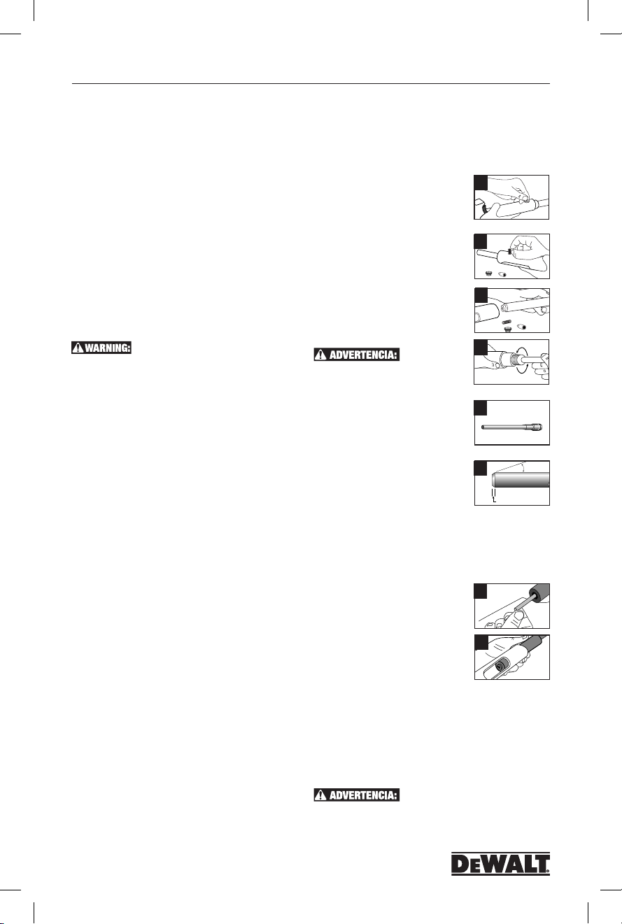
Modelo P2201 N.˚ de Cat. DDF211022P
P2201
una lata de agua u otro líquido no inflamable. Nunca trate
de forzar o hacer palanca una carga fuera de una cámara
de la herramienta. No se deshaga de cargas sin cocer en un
recipiente de basura.
6. Para prepararse para la siguiente operación de fijación,
apunte la herramienta en una dirección segura. Encaje
el barril hacia adelante tal como se describe en el
paso 1. Esta acción se puede extraer la carga de polvo
gastado y reponer adecuadamente el pistón. Siempre
inserte un nuevo sujetador antes de cargar la carga de
polvo en la cámara. No intente descargar o desmontar
una herramienta atascado o roto atascado como un
manejo inadecuado puede causar que se descargue
y el operador de huelga y / oa un observador. Una
herramienta atascada debe ser apuntada en una
dirección segura en todo momento. Tag la herramienta y
encerrarlo. Llame a su representante Fasteners D
para la asistencia adecuada.
Mantenimiento y limpieza
ASEGÚRESE DE QUE LA HERRAMIENTA
NO ESTÉ CARGADA. ASEGÚRESE DE QUE LA
HERRAMIENTA NO ESTÁ CALIENTE ANTES DE INTENTAR
EL DESARME O LA LIMPIEZA.
Prueba de funcionamiento diario
Compruebe el funcionamiento de la herramienta, sin una
carga de polvo o de fijación de la herramienta, empujando
hacia abajo contra la superficie de trabajo, apretar el gatillo,
y la liberación de la herramienta de la superficie de trabajo.
Función de la herramienta sin carga varias veces y aseguran
que las piezas que vienen de nalgas y mecanismo de disparo
operan libremente antes de la fijación con la herramienta.
Su representante autorizado D
que ayudará la primera vez de desmontar y limpiar su
herramienta. Si alguna vez tienen ningún problema de volver
a montar la herramienta, o si tiene alguna duda sobre las
piezas desgastadas, llame a su D
Distribuidor.
liLimpieza
Todas las piezas deben limpiarse con el aceite detergente
y los cepillos de alambre suministrados con el juego de
herramientas. Quite con el cepillo la suciedad gruesa
acumulada. Luego de la limpieza con aceite, se deben secar
completamente todas las piezas. El exceso de aceite tenderá
a acumular suciedad y polvo. Utilice la protección ocular
cuando limpie la herramienta. El exceso de suciedad en la
varilla del pistón, el montaje del cilindro y el receptor debe
limpiarse diariamente. Verifique la condición del pistón para
detectar daños por uso y deformaciones.
Para mantener esta herramienta en buenas condiciones
de funcionamiento, es necesario desensamblar y limpiar
toda la herramienta si hay evidencia de suciedad en el lado
de la recámara o si la herramienta parece perder potencia.
Se deben limpiar todas las piezas con aceite y cepillos de
alambre. Quite la acumulación de suciedad. Luego de la
limpieza con aceite, se deben secar completamente todas
las piezas.
El mantenimiento general de la herramienta se debe
realizar en intervalos de seis meses o más a menudo, según
lo requiera la frecuencia de uso de la herramienta.
EWALT debe pedir
EWALT autorizado Powder
Cómo reemplazar o reparar el pistón
El pistón es una pieza de desgaste y debe reemplazarse
periódicamente. Los signos típicos de un pistón desgastado
figuran: romper, doblar o recogida de setas. Para la revisión
de la herramienta asegúrese de que no hay carga de polvo
en la herramienta. Tenga cuidado y no perder o dañar los
componentes de la herramienta.
1. Afloje la tapa en el pin de reset
girando en sentido antihorario. Retire la
tapa de pasador de reposición.
2. Sostenga el cilindro en su lugar, a
continuación, quitar el muelle pin de
reset y reset pin.
3. Deslice el barril desde el receptor
tirando de él hacia delante. Si el exceso
de suciedad se acumula en el interior
del receptor, límpielo con un cepillo de
EWALT
alambre.
4. Desenrosque la pieza de la nariz
desde el cañón girando en sentido
contrario a las agujas del reloj. Tire del
émbolo hacia adelante fuera del cañón.
de tornillo de banco se utiliza para
mantener el barril, proteger el barril de
daños.
5. Limpiar el pistón con un cepillo de
alambre. Inspeccione para anillo de pistón
desgastados o dañados, extremo astillado
o flexión. Aplique lubricante al vástago
del pistón para reducir al mínimo la
adherencia de pistón de una condición de
sobreexcitación. Limpie el pistón seco.
6.
Si una punta del pistón está dañado,
se puede acortar un máximo de 0,20
pulgadas. La punta del pistón debe ser
plana y ranurada en 90 grados en el
vástago del pistón. El chaflán del pistón también debe reafilan
como se muestra. Pistón de molienda debe ser realizada por
personal cualificado, utilizando el equipo adecuado.
Rearmado:
7. Presione el pistón en el cilindro.
Enrosque la pieza de la nariz en el
barril y apriete hacia la derecha hasta
que quede firme dedo. Asegúrese de que
la pieza de la nariz esté completamente
asentada.
8. Alinear la ranura en el cañón con la
abertura del pasador de restablecimiento
en la parte inferior del receptor. Inserte
el cañón en la carcasa. Inserte el pin
de reset, y restablecer la primavera pin. Apriete la tapa
de pasador de restablecimiento del reloj hasta que quede
apretado y completamente acoplados.
Durante la instalación de la herramienta realice la siguiente
prueba. Presione la herramienta contra una superficie plana,
dura y apretar el gatillo. El conjunto de cuerpo debe deslizarse
suavemente dentro del receptor de la herramienta. El percutor
debe poner en libertad después de que el gatillo se ha tirado.
Si una abrazadera
ESTA PRUEBA DEBE REALIZARSE
SIN UN ALFILER O CARGA DE PÓLVORA EN LA
HERRAMIENTA.
1
2
3
4
5
6
7
8
10°
0.120"
17
POW2273_manual_P2201_dewalt.indd 17 3/10/14 12:41 PM
Page 18

P2201
Modelo P2201 N.˚ de Cat. DDF211022P
Solución de problemas
Siempre consulte el manual de instrucciones para realizar un ensamblaje adecuado de las piezas
PROBLEMA CAUSA POSIBLE SOLUIÓN
Penetración excesiva del sujetador
en el material
La herramienta no dispara No se presionó completamente la
Tool does not depress completely
completamente
Reducción de la potencia o
penetración insuficiente del
sujetador
La tira de la carga no puede
insertarse en la herramienta
La tira de carga no avanza Guía de la palanca de avance gastada Reemplace la guía de la palanca de avance. Esto debe ser
La carga no se dispara cuando
se aprieta el gatillo
La carga no se dispara cuando
la herramienta está presionada
completamente contra la
superficie de trabajo y se apretó
el gatillo
No se puede abrir la herramienta
ni realizar su ciclo
Pistón atascado en la posición
avance
Nivel de potencia demasiado alto/ Pasador
demasiado corto
Material base blando Consulte la sección de aptitud del material base
herramienta
Percutor dañado
Piezas del percutor, eyector, etc. dañadas
Piezas no ensambladas correctamente
No se empujó completamente el cilindro hacia
adelante al realizar el ciclo de la herramienta.
Pistón o aro del pistón gastados o dañados
Carga incorrecta Inserte la tira desde la parte inferior del mango de la
Tira de calibre incorrecto Utilice la tira adecuada
La herramienta no está completamente
presionada contra la superficie de trabajo
La carga ya se disparó Realice el ciclo de la herramienta
La carga se dispara de manera incorrecta Siga el procedimiento de seguridad
Percutor roto Reemplace la tuerca del percutor. Esto debe ser
Carga rota o falta de carga Reemplace la tuerca del percutor. Esta tuerca del
Falta de limpieza adecuada
Pistón dañado o doblado
Piezas rotas o dañadas Coloque una etiqueta en la herramienta con una
de
El pistón se ha colocado demasiado adentro y
está atascado contra el pasador
de reajuste del pistón
Reemplace las piezas dañadas
Utilice un nivel de carga de pólvora más bajo o un
pasador más largo
Consulte la sección “La herramienta no se presiona
completamente” a continuación
Verifique las piezas para detectar daños o un
ensamblaje inadecuado
El cilindro debe empujarse completamente hacia afuera
reajustar correctamente el pistón
Reemplace el pistón o el aro del pistón
herramienta
realizado por personas calificadas
Siga el procedimiento de seguridad para cargas mal
disparadas y luego intente presionar completamente la
herramienta contra la superficie de trabajo antes de
apretar el gatillo
realizado por personas calificadas
percutor debe ser reemplazada por personas calificadas
Limpie la herramienta completamente
Quite o reemplace el pistón
advertencia que diga “Defectuosa. No utilizar” en el
recipiente bloqueado y comuníquese con un representante
Autorizado de D
servicio
Golpee suavemente el pistón contra una superficie dura
EWALT para que le realice el
para
Pistón cortado o dañado La herramienta no se sostiene en la
La guía del pistón no se
abre fácilmente
La guía del pistón se abre El resorte de la bola anular o
superficie de trabajo directamente. Esto permite
que el pistón se deslice de la cabeza del
pasador y cause daños
al pistón
Abrazadera cortante doblada Quite y reemplace la abrazadera cortante
Acumulación excesiva de suciedad Desensamble y limpie la herramienta
El tope del pistón está dañado Reemplace el tope del pistón
Material extraño atascado Desensamble la herramienta y quite las partículas
bola anular de acero se ha gastado
have worn la
Pistón de la máquina como se muestra en la página 11.
nuevo pulido del pistón debe ser realizado únicamente por
personas calificadas
extrañas entre la guía del pistón y el montaje del
revestimiento de acero
Quite y reemplace por un resorte o una bola nuevos
El
18
POW2273_manual_P2201_dewalt.indd 18 3/10/14 12:41 PM
Page 19

Modelo P2201 N.˚ de Cat. DDF211022P
P2201
COMPANY NAME
EXAMEN DE OPERADOR CALIFICADO DE LA HERRAMIENTA
EL NUMERO DE SERIE MI HERRAMIENTA ES:
NOMBRE
DIRECCIÓN
NOMBRE DEL OPERADOR FECHA
DOMICILIO
EDAD FEDHA DE NACIMIENTO
3
☐ Marque la respuesta correcta.
1 Es necesario leer el Manual del operador antes de
operar una herramienta de baja velocidad
DEWALT. ☐Verdadero ☐Falso
2 Al aplicar sujetadores en concreto, el material
base debe ser mayor que la penetración de la
espiga, como mínimo: ☐1 vez ☐2 veces ☐3 veces
3 Al operar una herramienta accionada por pólvora,
nunca deberá colocar la mano:
☐ alrededor del cuerpo de la herramienta
☐ delante de la boca del cañón de la herramienta
☐ sobre el mango de la herramienta
4 Para determinar la aptitud de un material base,
utilice el sujetador como un punzón de marcar.
•Sielsujetadorseachata,norealicelasujeción;el
material es demasiado:
☐ blando ☐ duro ☐quebradizo
•Sielsujetadorpenetrafácilmente,norealicela
sujeción;elmaterialesdemasiado::
☐ blando ☐duro ☐ quebradizo
•Sielmaterialseagrietaosequiebra,norealicela
sujeción;elmaterialesdemasiado:
☐ blando ☐ duro ☐ quebradizo
5 ¿Cuál de las siguientes condiciones puede ser la
causa de aplicaciones no seguras de herramientas
accionadas por pólvora?
☐un material base blando
☐carga de pólvora inadecuada
☐sujeción demasiado cercana a un borde sin apoyo
☐una herramienta que funciona incorrectamente
☐sujeción en un área con desprendimiento
☐sujeción a través de un orificio preexistente
☐todas las anterioreo
6 ¿Cuál de los siguientes materiales de construcción
no es adecuado como material receptor (material base)
para los sujetadores acciona dos por pólvora?
☐roca laminada ☐ madera ☐ fibra de vidrio
☐ metal laminado ☐ todos los anteriores
ACTIVACIÓN DE LA LICENCIA Y LA GARANTÍA
LA HERRAMIENTA P2201 CUENTA CON UNA GARANTÍA DE 3 AÑOS A PARTIR DE LA FECHA DE COMPRA A LOS FABRICANTES DEFECTOS.
Certifico que he leído y comprendido el Manual de instrucciones para operar la herramienta P3500 y he realizado el examen del operador. Comprendo la importancia
de seguir todos los procedimientos de seguridad y que la falta de lectura, comprensión y cumplimiento con las reglas y advertencias detalladas respecto de la
operación segura de las herramientas accionadas por pólvora pueden ocasionar lesiones graves e incluso la muerte del operador de la herramienta o de las personas
que se encuentren en el lugar. Acepto cumplir con todas las reglas y regulaciones respecto del uso de las herramientas accionadas por pólvora.
(Escriba en letra de molde con claridad)
CORTE A LO LARGO DE LA LÍNEA DE PUNTOS, COLOQUE EN UN SOBRE, ESCRIBA LA DIRECCIÓN COMO SE MUESTRA Y ADJUNTE EL FRANQUEO
EnvíE mi licEncia para opErar la hErramiEnta a:
7 Al evaluar la seguridad de una aplicación en particular,
el operador debe pensar en:
☐ el material base
☐ el nivel de potencia de la carga de pólvora
☐ la seguridad del operador
☐ la seguridad de las personas que se encuentran en
el lugar y compañeros de trabajo
☐ todas las anteriores
8 El procedimiento de carga correcto consiste en:
insertar primero el sujetador y luego la carga de
pólvora. El sujetador siempre debe ser colo
cado en la herramienta antes que la carga.
☐Verdadero ☐Falso
9 ¿Cuál de los siguientes materiales generalmente es
adecuado para las sujeciones accionadas por
pólvora? ☐concreto vertido ☐teja hueca
☐ superficie de acero cementado ☐ladrillo vidriado
10 En concreto, un sujetador debe ser colocado en
un borde sin apoyo a una distancia no menor a:
☐ 1/2” ☐ 1-1/2” ☐3”
11 Fishhooking es una condición que puede ocur rir
cuando un sujetador accionado por pólvora golpea
una pieza de material agregado duro o concreto
muy duro, se dobla y sale de la superficie de trabajo.
Una circunstancia de Fishhooking puede ocasionar
lesiones graves e incluso la muerte. ☐Verdadero
☐Falso
12 Colocar una mano sobre el casquillo de la boca del
cañón de una herramienta cargada puede ocasionar
lesiones graves ya sea porque el pistón se coloque
demasiado adentro del material o porque se escape
un sujetador si la herramienta se dispara accidentalmente. ☐Verdadero ☐Falso
13 La aplicación excesiva de potencia en la herramienta
o el disparo de la herramienta contra una superficie
blanda hace que el pistón se coloque demasiado
adentro del material sobre el que se realiza la sujeción.
☐Verdadero ☐Falso
14 Las herramientas que no funcionan correctamente no
se deben utilizar y se deben eliminar inmediatamente
del servicio. ☐Verdadero ☐Falso
DIRECCIÓN DE LA COMPAÑA
NÚMERO TELEFÓNICO DE LA COMPAÑA
FIRMA FECHA
15 Luego de realizar la Prueba del punzón de marcar, la
mejor manera de verificar el material base consiste
en colocar varios sujetadores utilizando la carga de
menor potencia. ☐Verdadero ☐Falso
16 Las protección para los ojos y la protección auditiva
no deben ser utilizadas por el operador ni por ningún
transeúnte cuya presencia en los alrededores sea
necesaria al operar la herramienta.
☐Verdadero ☐Falso
17 Una herramienta accionada por pólvora no puede ser
utilizada de manera segura en un ambiente explosivo
o inflamable. ☐Verdadero ☐Falso
18 Escriba el número correcto del nivel de lacarga de
pólvora (1 a 6) junto a cada color enumerado.
Rojo ___ Marrón ___Verde ___Amarillo__
Gris ___ Violeta ___
19 Se debe utilizar el nivel de potencia más bajo al
realizar la primera sujeción. ☐Verdadero ☐Falso
20 Puede sujetar áreas de acero soldadas.
☐Verdadero ☐Falso
P2201
•Elprocedimientocorrectoenloscasosenquenose
produzca la ignición de la carga de pólvora consiste en
sostener la herramienta contra la superficie de trabajo
y esperar 30 segundos, y luego continuar exactamente
como lo indica el Manual del operador.
☐Verdadero ☐Falso
•LascargasdepólvoraD
P2201 son los cartuchos de pliegue corto, con ignición
en anillo y cuello hacia abajo, cónicos “A”, calibre 0,22.
No sepuede utilizar ninguna otra carga de pólvora en
esta herramienta. ☐Verdadero ☐Falso
•Losoperadoresnuncadebenpresionarlaunidad
P2201 ni ninguna otra herramienta accionada por
pólvora contra ninguna parte del cuerpo.
☐Verdadero ☐Falso
•Sieldispositivointermediodeunpistóndela
herramienta P2201 se deforma, simplemente
quítelo y utilice la herramienta sin el dispositivo.
☐Verdadero ☐Falso
EWALT para la herramienta
#
CIUDAD ESTADO CÓDIGO POSTAL NÚMERO TELEFÓNICO
ENVIAR POR CORREO A: Tool License Coordinator • DEWALT, Inc.• 2 Powers Lane, Brewster, NY 10509
19
POW2273_manual_P2201_dewalt.indd 19 3/10/14 12:41 PM
Page 20

P2201
ModÈlE P2201 No dE Cat. DDF211022P
R2200
P2201
MANUEL D’INSTRUCTIONS
Pistolet de
scellement
LU CE MANUEL ET AVANT D’AVOIR REÇU LA FORMATION CORRESPONDANT À LA
NORME ANSI A 10.3-1995.
VEUILLEZ LIRE ATTENTIVEMENT LE MANUEL D’INSTRUCTIONS
AFIN D’EN COMPRENDRE LE FONCTIONNEMENT DANS SON
INTÉGRALITÉ.
UNE FORMATION ADÉQUATE SUIVANT LA NORME ANSI A 10.3
« EXIGENCES DE SÉCURITÉ CONCERNANT LES DISPOSITIFS DE
SCELLEMENT AU PISTOLET » DOIT ÊTRE SUIVIE ET UNE CARTE
D’OPÉRATEUR QUALIFIÉ PAR D
AVANT DE POUVOIR UTILISER CET OUTIL. LES RÉGLEMENTATIONS
LOCALES, PROVINCIALES ET NATIONALES DOIVENT ÉGALEMENT
ÊTRE SUIVIES. LES LOIS, RÉGLEMENTATIONS ET STANDARDS
CONCERNANT L’UTILISATION DES OUTILS DE SCELLEMENT
AU PISTOLET SONT SUSCEPTIBLES D’ÊTRE RÉVISÉS
PÉRIODIQUEMENT. DE TELLES RÉVISIONS PEUVENT DONC
AVOIR UN IMPACT SUR LES PROCÉDURES DE SÉCURITÉ ET DE
FONCTIONNEMENT DÉCRITES DANS CE MANUEL. DEWALT INC.
N’EST PAS RESPONSABLE DES MODIFICATIONS APPORTÉES
APRÈS LA PUBLICATION DE CE MANUEL. IL EST DE LA
RESPONSABILITÉ DE L’UTILISATEUR DE SE MAINTENIR INFORMÉ
DES LOIS, RÉGLEMENTATIONS ET STANDARDS EN COURS QUI
S’APPLIQUENT AU PISTOLET DE SCELLEMENT.
: Ne mettez jamais la main sur la bouche du canon du pistolet.
R2200
CANON N’EST PAS POSÉ CONTRE LA SURFACE DE TRAVAIL ET
QUE VOUS ÊTES PRÊT À INSTALLER UNE ATTACHE. NE PLACEZ
JAMAIS LA MAIN SUR LA BOUCHE DU CANON LORSQU’IL EST
CHARGÉ. SI L’OUTIL SE DÉCHARGE ACCIDENTELLEMENT, LE
PISTON OU L’ATTACHE POURRAIT S’ENFONCER DANS VOTRE MAIN
ET VOUS BLESSER GRAVEMEN.
IFONCTIONNEMENT DE L’OUTIL DOIT LIRE ET
COMPRENDRE LE MANUEL DE L’OUTIL ENSEMBLE
ET DOIT COMPLÉTER L’EXAMEN DE L’OPÉRATEUR
SUR LA DERNIÈRE PAGE. L’OUTIL DE GARANTIE NE SERA PAS
VALIDE JUSQU’À CE QUE LE TEST EST REÇU, AVEC UNE COPIE DE
VOTRE REÇU, ET A PASSÉ EN REVUE PAR D
AVANT D’UTILISER LE P3500,
EWALT DOIT ÊTRE OBTENUE
Pour éviter toute blessure grave ou mortelle
Les utilisateurs et personnes à proximité
doivent porter des lunettes de protection ainsi
qu’une protection anti-bruit.
FAITES COMME
SI L’OUTIL EST TOUJOURS
CHARGÉ. NE PLACEZ PAS
LE DOIGT SUR LA DÉTENTE
DE L’OUTIL TANT QUE LE
EWALT, INC.
à basse vélocité
N’UTILISEZ PAS LE P3500 AVANT D’AVOIR
Garantie
Trois ans de garantie limitée
D
EWALT réparera, sans frais, tous les défauts dus aux
matériaux ou de fabrication pendant trois ans à compter de
la date d’achat. Cette garantie ne couvre pas les défaillances
de pièce dues à une usure normale ou abusive de l’outil.
Pour plus de détails de la garantie et de l’information
de réparation sous garantie, visitez www.dewalt.com ou
composez le 1-800-4-DEWALT (1-800-433-9258). Cette
garantie ne s’applique pas aux accessoires ni aux dommages
causés par des réparations ont été effectuées ou tentées par
d’autres. Cette garantie vous donne des droits spécifiques
tout vous pouvez avoir d’autres droits qui varient dans
certains états ou provinces.
En plus de la garantie, les outils DEWALT sont couverts par notre:
D
EWALT entretiendra l ‘outil et remplacera les pièces usées
par une utilisation normale, gratuitement, en tout temps au
cours de la première année suivant l’achat.
Si vous n’êtes pas complètement satisfait de la performance
de votre outil D
quelconque, vous pouvez le retourner dans les 90 jours
à compter de la date d’achat avec une réception pour un
remboursement complet - sans poser de questions.
GRATUIT DE LABEL DE REMPLACEMENT:
Si vos étiquettes d ‘avertissement deviennent illisibles ou
sont manquantes, composez le 1-800-4-DEWALT (1-800433-9258) pour un remplacement gratuit
1 AN DE SERVICE GRATUIT
REMBOURSEMENT DE 90 JOURS GARANTIE
EWALT charge explosive pour une raison
Introduction
Merci pour l’achat de l’outil actionné DEWALT P2201
de poudre à faible vitesse. Cet outil vous donnera
d’excellentes performances à condition que les étapes pour
le fonctionnement et l’entretien sont respectées. Systèmes
de fixation à charge explosive peuvent fournir une méthode
rentable de fixation pour appareils légers, des conditions
de charge statique. Les systèmes fournis par D
composent d’éléments de fixation spécialement conçus,
des outils d’installation, et les charges de poudre qui sont
conçus pour fonctionner en combinaison pour fournir
une performance optimale. Alors que les outils à charge
explosive peuvent fournir l’un des moyens les plus rapides
et économiques de fixation, ils peuvent aussi être dangereux
EWALT se
™
20
POW2273_manual_P2201_dewalt.indd 20 3/10/14 12:41 PM
Page 21

ModÈlE P2201 No dE Cat. DDF211022P
P2201
s’ils ne sont pas exploités correctement.
Stop
Spall
Avant d’utiliser l’outil de P2201, vous devez être
correctement formé à l’exploitation et la maintenance de cet
outil et délivrera une carte de conducteur qualifié de D
Lors de l’utilisation de l’outil, vous devez avoir cette carte en
votre possession. Dans le cadre du processus de formation,
vous devez lire et comprendre le contenu de ce manuel
d’instruction surtout les consignes de sécurité.
Pistolets de scellement peuvent être utilisés que par des
opérateurs correctement formés comme décrit dans la norme
ANSI A 10.3, Règles de sécurité pour systèmes de fixation à
charge explosive. Pour les détails complets de fonctionnement
de l’outil, communiquez avec votre bureau de la Direction
générale de D
EWALT ou distributeur local pour la formation.
Rappelez-vous, la sécurité commence avec vous! Il est de
votre responsabilité principale lors de l’utilisation de cet outil.
Le non-respect des procédures d’exploitation, de maintenance
et de sécurité appropriées peut entraîner des blessures graves
ou la mort pour vous ou des tiers. En plus de la formation
offerte, vous devez être familier avec les règlements locaux,
étatiques et fédéraux. Si vous avez des questions qui ne sont
pas couverts dans ce manuel, contactez votre bureau de la
Direction de D
EWALT ou distributeur local.
Fourchette de dimensions
Clous de 1/2 à 3 po de long et de calibre .22
Description de l’outil
Le P2201 est un faible vitesse, tir simple, 0,22 outil de
calibre qui peut être utilisé pour installer 0,300 broches
d’entraînement de la tête, 8mm broches d’entraînement
de la tête et 1/4 “-20 tiges filetées, jusqu’à 3” de longueur
totale. Le P2201 est conçu pour un entretien ou des
entrepreneurs résidentiels.
DONNÉES TECHNIQUES
CORPS DE L’OUTIL LONGUER DU CLOU LONGUER DE L’OUTIL
Conçu en plastique Longuer totale de 12-1/2”
1/2 po à 3 po
TYPE DE CARTOUCHE POIDS DE L”OUTIL NIVEAU DE CHARGE
.22 Caliber à 4.3 lb Gris (1), Brun (2),
serti “A” Charger Vert (3), Jaune (4)
TYPE DE CLOU
Clou à pointe balistique, clou à tête de 0,300 po, clou à tête de 8 mm,
goujon fileté de 1/4 po-20
Fonctionnement dans le béton
La performance d’une attache à
Washer
scellement à cartouche, une fois
EWALT.
installée dans le béton ou dans les
matériaux de maçonnerie, est établie en
fonction des facteurs suivants :
1. La résistance du matériau de base
2. La dureté et la concentration des
Stop
Spall
agrégats
3. Le diamètre de la tige de l’attache
4. La profondeur d’enrobage dans le
matériau de base
5. L’espacement entre les attaches et
la marge de bordure
En plus de ces facteurs, l’utilisation
d’accessoires comme un pare-éclats qui, posé sur du
béton, permet de réduire sa tendance à éclater pendant
l’enfoncement, peuvent augmenter la performance de
l’attache.
Lorsqu’une attache à scellement à cartouche est
enfoncée dans le béton, elle déloge le volume de béton
autour de la zone dans laquelle la tige est enrobée. Ainsi,
le béton qui entoure directement l’attache est comprimé
puis reprend sa place autour du corps de l’attache. De
plus, l’enfoncement génère une chaleur faisant fondre
les particules du béton sur le corps de l’attache. Cette
combinaison de compression et de fusion fait en sorte de
retenir l’attache dans le matériau en béton. Une action
semblable se produit lorsque vous enfoncez une attache
dans un bloc de maçonnerie.
En règle générale, la performance de l’attache dans une
résistance donnée de béton augmentera dans une certaine
gamme avec la profondeur d’enrobage. Selon le type
d’attache et la résistance du matériau de base, la gamme
de profondeurs d’enrobage varie de 5/8 po à 1-1/2 po. Pour
des profondeurs plus importantes, l’attache risque de plier
et de prendre une forme d’hameçon. Cela risque donc de
diminuer les capacités de charge attendues et de provoquer
des risques d’accident.
Pendant l’enfoncement, quelques éclatements localisés
peuvent se produire dans le béton. Normalement, il s’agit
d’un effet de surface qui n’a aucune incidence sur la
performance de l’attache. Toutefois, cet effet pourrait poser
un problème esthétique pour les applications exposées où
P2201 Guide de sélection
NO. DE CAT DESCRIPTION CARTON STANDARD.
DFC211022D P2201 Outil (Blister) 1
52522 Piston 1
52510 Nez Piece 1
52512 Piston Réinitialiser Pin 1
Fonctionnement de l’outil
aucun accessoire n’est utilisé. Dans de tels cas, il existe
deux méthodes pour améliorer l’apparence de l’attache. Une
méthode consiste à utiliser un adaptateur pare-éclats fixé
sur le pistolet de scellement afin d’aider à réduire les éclats
en surface. L’autre méthode consiste à enfoncer l’attache à
travers une rondelle d’acier pour améliorer l’apparence de
l’application.
Avant d’apprendre les procédures de sécurité pour cet outil,
il est important de comprendre comment un pistolet de
scellement fonctionne. Une attache à scellement à cartouche
est considérée comme une attache à enfoncement direct ou
à pénétration forcée car elle est directement enfoncée dans
le matériau de base. Cette action nécessite l’application
d’une force énorme sur l’attache. Les attaches à scellement
à cartouche de D
EWALTsont spécialement fabriquées en
suivant un processus de trempe étagée bainitique pour
supporter les forces imposées durant l’enfoncement. Seules
les attaches fabriquées ou fournies par D
EWALT devraient
être utilisées dans cet outil.
Fonctionnement dans l’acier
acité de charge d’une attache à
scellement à cartouche est établie en
fonction des facteurs suivants :
1. L’épaisseur de l’acier
2. La force de résistance à la traction de l’acier
3. Le diamètre de la tige de l’attache
4. La profondeur d’enrobage de la pointe de l’attache
dans l’acier
5. L’espacement entre les attaches et la marge de bordure.
Lorsqu’une attache à scellement à cartouche est
enfoncée dans l’acier, elle déplace latéralement l’acier à 360
21
POW2273_manual_P2201_dewalt.indd 21 3/10/14 12:41 PM
Page 22

P2201
ModÈlE P2201 No dE Cat. DDF211022P
degrés autour de la tige de l’attache. Puisque l’acier est un
matériau élastique, il exerce une pression contre le corps
de l’attache pour la maintenir en place. Lorsque le diamètre
de la tige de l’attache est augmenté, la capacité de la
charge obtenue s’accroît de façon générale, à condition que
l’épaisseur de l’acier soit suffisante pour accepter l’attache.
Pour augmenter la performance de l’attache dans l’acier,
certaines attaches sont dotées d’une tige moletée qui permet
à l’acier de former un verrouillage par blocage dans les
rainures afin de fournir des capacités plus élevées que celles
obtenues par une tige lisse. Pour une performance optimale,
la pointe de l’attache doit être complètement enfoncée dans
l’acier. Normalement, une longueur minimum de 1/4 po est
autorisée pour la pointe. On peut s’attendre à une hausse de
la performance jusqu’à ce que l’attache cesse de s’enfoncer
L’utilisation d’un pistolet de
scellement n’est pas recommandé si
vous observez les points suivants au
cours du test au pointeau :
1. La pointe de l’attache est émoussée.
Cela indique que le matériau de base
est trop rigide.
2. Le matériau de base se fissure ou
éclate. Cela indique que le matériau
de base est trop cassant.
3. Lorsque vous donnez un coup de
marteau moyen, l’attache pénètre
facilement dans le matériau de base.
Cela indique que le matériau de base
est trop mou.
1
2
complètement dans l’acier. À ce moment, les propriétés
élastiques de l’acier développent une force de compression
en angle contre la pointe de l’attache, ce qui réduit sa
capacité de charge. Dans les matériaux d’acier plus épais,
on peut obtenir des capacités adéquates de charge pour
des applications où la pointe de l’attache ne pénètre pas
complètement l’acier. Des tests de performance sur le terrain
sont recommandés.
Les attaches ne devraient pas être installées dans des
endroits qui ont été soudés ou coupés à la torche car ces
procédures peuvent avoir causé un durcissement local de
l’acier. Il vaut mieux éviter de trop enfoncer l’attache car
le rebondissement créé peut réduire la capacité de charge
ou endommager l’attache. Lors d’une installation dans de
longues pièces d’acier non soutenues, il peut être nécessaire
de prévoir un soutien autour de l’attache afin de prévenir le
rebondissement qui pourrait causer une pénétration inégale
et une diminution de la capacité de charge.
Matériau de base adapté
Bien que les attaches à scellement peuvent être utilisées
avec succès dans le béton, dans certains matériaux de
maçonnerie et dans l’acier A 36, d’autres matériaux de
base ne conviennent pas du tout. Les attaches ne devraient
jamais être installées dans des matériaux solides ou cassants
tels que la fonte, la céramique, le verre ou la pierre. Ces
matériaux peuvent éclater facilement entraînant ainsi des
risques potentiels d’accident. De plus, les matériaux mous
tels que le panneau mural, le plâtre, ou les bois ne sont pas
appropriés, car l’attache peut traverser complètement ces
matériaux. L’utilisateur ne devrait jamais courir de risques
lorsqu’il installe une attache dans un matériau de base. Le
non-respect des instructions d’installation et de sécurité
risque de provoquer des blessures graves ou mortelles à
l’opérateur et/ou aux personnes à proximité.
Test au pointeau
Un test au pointeau doit toujours être effectué afin de
déterminer la compatibilité du matériau de base destiné
à recevoir l’attache à scellement à cartouche. Ce test est
Exigences d’installation de
l’attache
Il est important de comprendre les
exigences relatives à l’épaisseur
minimum du matériau de base ainsi que
les exigences concernant l’espacement
et la marge de bordure minimum. Le non-respect de ces
instructions peut provoquer des problèmes au niveau de
l’attache et entraîner des risques potentiels d’accident.
Épaisseur du matériau de base
Le matériau en béton devrait être au moins trois (3) fois plus
épais que la profondeur d’enrobage de l’attache. Si le béton
est trop mince, les forces de compression qui pèsent sur les
pointes des attaches peuvent provoquer une rupture de la
face libre du béton. Les morceaux de béton ou d’attache qui
tombent peuvent être dangereux et entraîner une diminution
de la résistance à l’arrachement de
l’attache. Pour les applications dans
la paroi de face du bloc de béton,
choisissez une attache dont la longueur
ne dépasse pas l’épaisseur de la paroi.
Guide de pénétration des attaches
Le tableau qui suit indique les profondeurs
de pénétration ou d’enrobage typiques pour
chaque matériau de base. La pénétration
varie selon la densité du matériau. Ce
tableau doit donc être utilisé comme un guide puisque la densité
de ces matériaux peut varier. Lorsque vous avez un doute, nous
vous recommandons d’effectuer des essais de performance sur
le terrain.
DENSITÉ
Matérau mou de maçonnerie Bloc de béton 1 po -1-1/4 po
Béton de densité moyenne Béton coulé 3/4 po - 1 po
Béton dense Béton précontraint 5/8 po - 3/4 po
préfabriqué
BASE DE MATÉRIAU TYPIQUE
3
Penetration
PÉNÉTRATION
relativement simple et peut aider à assurer un attachement
efficace et sécuritaire. Assurez-vous de porter des lunettes
de protection lorsque vous effectuez ce test. Avant de
commencer, sélectionnez l’attache à utiliser pour le travail.
Placez ensuite la pointe de l’attache sur le matériau de base
à tester. Frappez l’attache d’un seul coup de marteau, puis
examinez la pointe de l’attache. Si la pointe de l’attache
n’est pas émoussée et que le matériau de base présente un
point d’indentation clair, il est acceptable de procéder à la
première installation d’essai
Marge de bordure
N’installez pas d’attache à moins de 3
po de la bordure du béton. Si le béton
se fissure, il se peut que l’attache
ne résiste pas. Il est possible de
diminuer la marge de bordure pour des
applications comme les bas de porte si un essai d’attache a
été exécuté.
Point
Flattens
No
Indent
Surface
Shatters
Material
Cracks
Fastener Sinks in
with Average
Hammer Blow
3x
Penetration
3"
22
POW2273_manual_P2201_dewalt.indd 22 3/10/14 12:41 PM
Page 23

ModÈlE P2201 No dE Cat. DDF211022P
P2201
Espacement
Le positionnement des attaches trop
près l’une de l’autre dans le béton ou
dans la maçonnerie peut provoquer
des fissures. La distance minimale
3"
recommandée entre les attaches est de
3 po d’entraxe.
Sélection de la longueur de
Fixture
l’attache dans du béton
Avant d’installer des tiges pour un
Embedment
montage permanent dans le béton,
déterminez d’abord l’épaisseur du
montage qui doit être installé. À
ce résultat, ajoutez la profondeur
d’enrobage ou de la pénétration requise dans le matériau de
base. Vous obtiendrez la longueur nécessaire pour la tige de
l’attache. Pour des applications dans la paroi de face d’un
bloc de béton, sélectionnez une attache dont la longueur ne
dépasse pas l’épaisseur de la paroi de face.
Pour des applications amovibles avec goujons filetés,
la longueur de la tige nécessaire est égale à la profondeur
d’enrobage requise. Pour déterminer la longueur minimale du
filetage, additionnez l’épaisseur du montage avec l’épaisseur
obtiendrez la longueur minimale de la tige de l’attache à
utiliser. Ne choisissez pas une attache plus longue que celle
requise pour l’application. Une tige excessivement longue
peut brunir ou polir le trou créé dans l’acier et provoquer une
diminution de la capacité de charge.
Pour ce qui est des applications amovibles avec goujons
filetés, la longueur de la tige requise est égale à l’épaisseur
du matériau de base en acier plus un minimum de 1/4 po
pour permettre la pénétration de la pointe de l’attache. Vous
obtiendrez la longueur minimale de la tige de l’attache à
utiliser. Ne choisissez pas une tige plus longue que celle
requise pour l’application. Une tige excessivement longue
peut brunir ou polir le trou créé dans l’acier et provoquer
une diminution de la capacité de charge. Pour déterminer
la longueur minimale du filetage, additionnez l’épaisseur
du montage avec l’épaisseur de l’écrou et de la rondelle.
L’épaisseur de l’écrou et de la rondelle est égale au diamètre
nominal du filetage.
Ne serrez pas trop les goujons filetés, les valeurs
maximales de couple de serrage sont énumérées dans le
tableau ci-dessous. L’utilisation d’une noix de serrage est
recommandée pour réduire le risque de trop serrer les attaches.
Pour les applications critiques, effectuez un essai sur le terrain.
de l’écrou et de la rondelle. L’épaisseur de l’écrou et de la
rondelle est égale au diamètre nominal du filetage. Ne serrez
pas trop les pièces filetées. Les valeurs maximales de couple
de serrage sont énumérées dans le tableau ci-dessous.
L’utilisation d’une noix de serrage est recommandée pour
réduire le risque de trop serrer les attaches. Pour les
applications critiques, effectuez un essai sur le terrain.
COUPLE MAXIMUM POUR GOUJON COUPLE MAXIMUM POUR GOUJON
DE 1/4 PO (PI-LB) DE 3/8 PO (PI-LB)
2 4
Installation dans l’acier
Les indications suivantes sont basées sur l’installation d’une
attache dans de l’acier de construction de type ASTM A
36 et dont la pointe pénètre entièrement dans la pièce
d’acier. L’épaisseur recommandée pour les matériaux en
acier s’étend de 1/8 po au minimum à 3/8 po au maximum.
Pour des applications dans de l’acier de construction plus
dense dans lequel la pointe de l’attache ne pénètre pas
complètement, ou dans de l’acier dont l’épaisseur est
supérieure à 3/8 po, nous recommandons d’effectuer des
tests sur le terrain.
Épaisseur du matériau de base
Les matériaux de base en acier devraient avoir une épaisseur
minimale de 1/8 po.
Marge de bordure
Pour les installations dans de l’acier A 36, la marge de
bordure minimum recommandée est de 1/2 po.
Espacement
La distance minimale recommandée entre les attaches est
de 1-1/2 po d’entraxe pour les installations dans de l’acier
ASTM A 36 steel.
Sélection de la longueur de
l’attache dans de l’acier
1/8"
Avant d’installer des clous pour un
1/2"
montage permanent dans l’acier,
déterminez d’abord l’épaisseur du
Guide de sélection des cartouches
Clous à tête de 0,300 po
NO DE LONGUEUR BOÎTE CARTON DIAMÉTRE DIAMÈTRE POIDS/
CAT. DE LA STANDARD STANDARD DE LA DE LA 100
TIGE TÊTE TIGE
DDF3011000
1/2 PO M 100 5000 0,300 0,143 0,5
DDF3011050
5/8 PO M 100 5000 0,300 0,143 0,5
DDF3011100
3/4 PO 100 5000 0,300 0,143 0,5
DDF3011150
1 PO 100 5000 0,300 0,143 0,6
DDF3011200
1-1/8 PO 100 1000 0,300 0,143 0,7
DDF3011250
1-1/4 PO 100 1000 0,300 0,143 0,8
DDF3011300
1-1/2 PO 100 1000 0,300 0,143 0,9
DDF3011350
1-3/4 PO 100 1000 0,300 0,143 1,1
DDF3011400
2 PO 100 1000 0,300 0,143 1,2
DDF3011450
2-1/4 PO 100 1000 0,300 0,143 1,2
DDF3011500
2-3/8 PO 100 1000 0,300 0,143 1,3
DDF3011550
2-1/2 PO 100 1000 0,300 0,143 1,4
DDF3011600
2-3/4 PO 100 1000 0,300 0,143 1,6
DDF3011650
3 PO 100 1000 0,300 0,143 1,9
Clous à tête de 0,300 po à chapeau métallique
NO DE LONGUEUR BOÎTE CARTON DIAMÉTRE DIAMÈTRE POIDS/
CAT. DE LA STANDARD STANDARD DE LA DE LA 100
TIGE TÊTE TIGE
DDF3031000
1/2” K 100 5000 0,300 0,143 0,5
DDF3031050
5/8” K 100 5000 0,300 0,143 0,5
DDF3031100
3/4” 100 5000 0,300 0,143 0,5
DDF3031150
1” 100 5000 0,300 0,143 0,6
Clous à tige grossissante et à tête de 0,300 pl
NO DE LONGUEUR BOÎTE CARTON DIAMÉTRE DIAMÈTRE POIDS/
CAT. DE LA STANDARD STANDARD DE LA DE LA 100
TIGE TÊTE TIGE
DDF3041000
Clou à tige 100 1000 0,300 0,143/130 0,5
grossissante de 3/4 po
DDF3041050
Clou à tige 100 1000 0,300 0,143/130 0,6
grossissante de 1 po
montage qui doit être installé. À ce
résultat, ajoutez l’épaisseur du matériau
1-1/2"
de base en acier plus un minimum de
1/4 po pour permettre la pénétration
adéquate de la pointe de l’attache. Vous
23
POW2273_manual_P2201_dewalt.indd 23 3/10/14 12:41 PM
Page 24

P2201
ModÈlE P2201 No dE Cat. DDF211022P
Clous à tête de 0,300 po de diamètre - Carton maître
NO DE LONGUEUR BOÎTE CARTON DIAMÉTRE DIAMÈTRE POIDS/
CAT. DE LA STANDARD STANDARD DE LA DE LA 100
TIGE TÊTE TIGE
DDF301100M
1/2 po M 1000 5000 0,300 0,143 0,5
DDF301105M
5/8 po M 1000 5000 0,300 0,143 0,5
DDF301110M
3/4 po 1000 5000 0,300 0,143 0,5
DDF301115M
1 po 1000 5000 0,300 0,143 0,6
DDF301125M
1-1/4 po 1000 5000 0,300 0,143 0,8
DDF303100M
1/2 po M CM 1000 5000 0,300 0,143 0,5
DDF303105M
5/8 po M CM 1000 5000 0,300 0,143 0,5
DDF303110M
3/4 po CM 1000 5000 0,300 0,143 0,5
DDF303115M
1 po CM 1000 5000 0,300 0,143 0,6
M=Moleté C=Chapeau Métallique
Clous à tête de 0,300 po avec rondelle de 3/4 po
NO DE LONGUEUR BOÎTE CARTON DIAMÉTRE DIAMÈTRE POIDS/
CAT. DE LA STANDARD STANDARD DE LA DE LA 100
TIGE TÊTE TIGE
DDF3051100
3/4 po 100 1000 0,300 0,143 1,6
DDF3051200
2-1/2 po 100 1000 0,300 0,143 2,5
Clous à tête de 0,300 po avec rondelle de 7/8 po
NO DE LONGUEUR BOÎTE CARTON DIAMÉTRE DIAMÈTRE POIDS/
CAT. DE LA STANDARD STANDARD DE LA DE LA 100
TIGE TÊTE TIGE
DDF3061150
1 po 100 1000 0,300 0,143 1,9
DDF3061250
1-1/4 po 100 1000 0,300 0,143 2,0
DDF3061300
1-1/2” po 100 1000 0,300 0,143 2,1
DDF3061400
2 po 100 1000 0,300 0,143 2,4
DDF3061550
2-1/2 po 100 1000 0,300 0,143 2,7
DDF3061650
3 po 100 1000 0,300 0,143 3,0
Clous à tête de 0,300 po avec rondelle de 1 po
NO DE LONGUEUR BOÎTE CARTON DIAMÉTRE DIAMÈTRE POIDS/
CAT. DE LA STANDARD STANDARD DE LA DE LA 100
TIGE TÊTE TIGE
DDF3071000
1-1/4 po 100 1000 0,300 0,143 2,2
DDF3071050
1-1/2 po 100 1000 0,300 0,143 2,3
DDF3071250
2 po 100 1000 0,300 0,143 2,6
DDF3071150
2-1/2 po 100 1000 0,300 0,143 2,9
DDF3071200
3 po 100 1000 0,300 0,143 3,2
Clous à tête de 0,300 po avec Attaches à plafond
BX câble bretelles and Conduit Clips
NO DE LONGUEUR BOÎTE. CARTON
CAT. DE LA STD. STD. DE LA. DE LA. 100
TÊTE
DDF4111150
1 po 100 1000 0,300 0,143 3,5
DDF4131050
1-1/4 po 100 1000 0,300 0,143 3,7
DDF4121000
DDF4121050 3/4 po EMT 1-1/4 po pin
DDF4121100
DDF4121150
DDF4121200 1 po EMT 1 po pin TH
K=moletée TH= chapeau haut de forme
Clous à tête de 0,300 po avec clip
NO DE BOÎT. CARTON
CAT. DESCRIPTION STD. STD. DE LA DE LA 100
TÊTE TIGE
DDF4251000
DDF4251050
DDF4251150
DDF4252000
DDF4252500
Clous pour coffrage
NO DE BOÎTE CARTON.
CAT. DESCRIPTION STD. STD. DE LA DE LA 100
TÊTE TIGE
DDF3951050
DDF3951000
1/2 po EMT 1 po pin
3/4 po EMT 1 po pin TH
3/4 po EMT 1 po pin 100 1000 0,300 0,143 3,3
32mm/c. de r. 100 100 8mm 0,143 4,0
37mm/c. de r. 100 100 8mm 0.143 4,1
37mm/c. de r. 100 100 8mm 0,143 4,4
37mm/c. de r. 100 100 8mm 0,143 4,6
37mm/c. de r. 100 100 8mm 0,143 4,8
62mm - 2-1/2 po 100 1000 0,205 0,143 1,4
44mm - 1-5/8 po 100 1000 0,205 0,143 1,2
100 1000 0,300 0,143 3,3
100 1000 0,300 0,143 3,5
100 500 0,300 0,143 3,4
25 250 0,300 0,143 3,2
DIAMÉTRE DIAMÉTRE
DIAMÉTRE DIAMÉTRE
DIAMÉTRE DIAMÉTRE POIDS
Guide de sélection des cartouches
NO. DE NIVEAU COULEUR BOÎTE CARTON CARTON POIDS/
DE DE LA TAILLE STD. STD. MAÎTRE 100
CHARGE CARTOUCHE
DDF1111100
1 Gris 0,22A 100 1000 20000 0,33
DDF1111200
2 Brun 0,22A 100 1000 20000 0,33
DDF1111300
3 Vert 0,22A 100 1000 20000 0,33
DDF1111400
4 Jaune 0,22A 100 1000 20000 0,33
Clous à tête de 0,300 po avec rondelle d’étanchéité
de 1-7/16 po
NO DE LONGUEUR BOÎTE CARTON DIAMÉTRE DIAMÈTRE POIDS/
CAT. DE LA STANDARD STANDARD DE LA DE LA 100
TIGE TÊTE TIGE
DDF3081000
1-1/2 po 100 1000 0,300 0,143 2,1
DDF3081050
2-1/2 po 50 500 0,300 0,143 2,7
Goujons filetés de 1/4 po-20
NO DE LONGUEUR LONGUER BOÎTE CARTON DIAMÉTRE DIAMÈTRE POIDS/
CAT. DU DE LA STANDARD STANDARD DE LA DE LA 100
FILETAGE TIGE TÊTE TIGE
DDF3811020
1/2 po 1/2 po K 100 5000 1/4 po 0,143 0,8
DDF3811000
3/4 po 1/2 po K 100 1000 1/4 po 0,143 1,1
DDF3811050
3/4po 3/4 po K 100 1000 1/4 po 0,143 1,2
DDF3811100
1/2 po 1 po K 100 1000 1/4 po 0,143 1,2
DDF3811150
3/4 po 1 po K 100 1000 1/4 po 0,143 1,4
DDF3811180
1/2 po
1-1/4 K po
DDF3811200
3/4 po
DDF3811250
1-1/4 K 1-1/4 K po
Clous à tête de 0,300 po avec Attaches à plafond
NO DE LONGUEUR BOÎTE. CARTON.
CAT. DE LA STD. STD. DE LA. DE LA. FIL 100
TÊTE
DDF4111050
1 po 100 1000 0,300 0,143 0,278 po 3,5
DDF4151000
1 po 100 1000 0,300 0,143 0,278 po 3,0
DDF4111100
1-1/4 po 100 1000 0,300 0,143 0,278 po 3,7
DDF4111150
1-1/4 po 100 1000 0,300 0,143 0,278 po 3,2
100 1000 1/4 po 0,143 1,4
1-1/4 K po
100 1000 1/4 po 0,143 1,5
100 1000 1/4 po 0,143 1,7
DIAMÉTRE
DIAMÉTRE
TIGE
TROU POIDS/
TY INSTRUCTIONS
CONSIGNES DE SÉCURITÉ
Vous êtes responsable de la sécurité lorsque vous utilisez
un pistolet de scellement. Vous devez lire et comprendre
l’intégralité de ce manuel. Vous devez vous familiariser avec
toutes les fonctions et règles de sécurité reliées à l’outil. Il
est de votre responsabilité de suivre la formation adéquate
afin d’obtenir la carte d’opérateur D
outil en suivant la norme actuelle ANSI A10.3 « Exigences de
sécurité concernant les dispositifs de scellement au pistolet »
ainsi que les normes nationales de sécurité et de santé au
travail. Les réglementations locales, provinciales et
nationales doivent également être suivies. Lorsque vous
utilisez cet outil, vous devez avoir en votre possession la
carte d’opérateur qualifié.
Annulation de la carte - Le non-respect de l’un des
règlements liés à la sécurité des pistolets de scellement
cause l’annulation immédiate de votre carte d’opérateur
qualifié.
instructions de sécurité peut entraîner des blessures
graves ou la mort à des opérateurs ou des passants.
EWALT avant d’utiliser cet
Le défaut de suivre les
24
POIDS/
TIGE
POIDS
/
/
POW2273_manual_P2201_dewalt.indd 24 3/10/14 12:41 PM
Page 25

ModÈlE P2201 No dE Cat. DDF211022P
P2201
Avant d’utiliser l’outil
1. Des panneaux de mise en garde doivent toujours être
affichés dans la zone dans laquelle vous utilisez un
pistolet de scellement. Ces panneaux doivent avec une
taille minimale de 8 po x 10 po et l’inscription doit être
en caractères gras d’au moins 1 po de haut. Le panneau
doit indiquer la mention « Pistolet de scellement en cours
d’utilisation.
2. Des lunettes protection approuvées doivent toujours être
portées par l’opérateur et par les personnes à proximité
afin de protéger leurs yeux des particules volantes. Des
protections anti-bruit doivent également être portées
par l’opérateur et les personnes à proximité lors de
l’utilisation d’un pistolet de scellement. Tout autre
protection adéquate doit également être utilisée.
3. Ne jamais modifier ou fabriquer de pièce pour votre
outil D
EWALT. Utilisez uniquement des attaches, des
cartouches et des pièces de la marque D
4. Ne jamais poser la main ou toute autre partie du corps
sur la bouche du canon ou sur le canon de l’outil. Une
décharge accidentelle peut envoyer le piston et/ou
l’attache à travers la main de l’opérateur.
5. Ne comprimez jamais l’outil contre vous. Vous risqueriez
de vous blesser gravement ou mortellement si l’outil se
décharge accidentellement.
6. Pointez toujours l’outil vers un endroit non dangereux.
EWALT.
Usage Prévu
7. Gardez toutes les autres personnes, en particulier les
enfants, à l’écart de la zone de travail.
8. Utiliser uniquement dans un espace de travail bien ventilé
et bien éclairé.
Préparation en vue de charger l’outil
1. Avant l’utilisation, il est nécessaire de vérifier que l’outil
n’est pas chargé entièrement ou partiellement avec une
cartouche ou une attache.
2. Pour vous assurer que l’outil fonctionne en toute
sécurité, effectuez quotidiennement le test décrit dans ce
manuel. Assurez-vous que l’outil n’est pas chargé avant
d’effectuer ce test.
3. N’utilisez pas cet outil à moins qu’il ne soit entièrement
monté et que toutes les pièces fonctionnent correctement.
N’utilisez jamais un outil défectueux. Appelez le
1-800-4-DEWALT pour obtenir de l’aide.
4. Ne supposez jamais qu’un matériau de base est adéquat.
Si vous n’êtes pas certain qu’il est adéquat, effectuez un
test au pointeau.
5. N’utilisez pas l’outil sans avoir appris et compris le code
des couleurs et le système de numérotation utilisé pour
identifier le niveau de charge des cartouches.
Utiliser l’outil
1. N’utilisez que les fixations et les charges de poudre
conçus pour cet outil, tel que fourni par D
2. Do not use powder actuated tools in the presence of
flammable fumes or vapor or an explosive atmosphere.
3. Ne pas utiliser des outils à charge explosive, en présence
de vapeurs inflammables ou de la vapeur ou une
atmosphère explosive.
4. Ne pas charger l’outil jusqu’à ce que vous êtes prêt
à faire une fixation. Vérifiez le niveau de charge de
puissance avant de l’insérer dans la chambre de l’outil.
5. Fixation doit être chargé avant le chargement de la
charge de poudre, pour éviter de blesser l’opérateur ou
spectateur dans le cas d’un déversement accidentel.
EWALT.
6. Ne fermez pas l’outil contre la surface de travail. L’outil
doit être fermé manuellement, avec la main loin de la
bouche / baril pour éviter une décharge accidentelle.
7. Tenez l’outil perpendiculaire à la surface de travail à tout
moment. Utilisez une garde d’éclats (pièce n ° 52166)
la mesure du possible. Cela permettra de limiter la
possibilité de fixation ricochet qui pourrait causer des
blessures graves ou la mort à l’opérateur ou des tiers.
Pour commander garde éclats option sans appel de
charge 1-800-4-DEWALT.
8. Toujours effectuer un test de fixation du niveau de charge
le plus léger conçu pour être utilisé dans l’outil. Si la charge
la plus faible ne définit pas la fixation, essayez la prochaine
charge la plus élevée jusqu’à ce que le niveau correct soit
atteint. Le non respect de cette procédure peut entraîner
la fixation à maîtrisé. Si cela se produit, la fixation peut
pénétrer complètement le matériau de base et causer des
blessures graves ou la mort à quelqu’un. Accablante la
fixation peut également endommager l’outil, la création
d’un danger pour la sécurité à la fois l’opérateur ou des
tiers.
9. Ne serrez pas en fonte, carrelage, verre, ou d’autres
types de matériaux fragiles. Ces matériaux peuvent se
briser et créer des fragments tranchants qui peuvent
causer des blessures.
10. Ne pas déclencher l’outil à l’intérieur de 3 “(trois pouces)
du bord d’un matériau de base de béton ou à l’intérieur
de 1/2” (un demi-pouce) du bord d’un matériau de base
en acier.
11. Ne pas essayer d’installer un dispositif de fixation à
moins de 3 “(trois pouces) à un autre élément de fixation
préalablement introduit dans le béton ou 1-1/2” (un et un
demi-pouce) en acier.
12. Ne pas fixer dans un matériau de base en béton moins 3
fois plus épaisse que la pénétration de fixation ou dans
un matériau de base en acier plus mince que 1/8 “.
13. Ne jamais essayer d’installer une attache dans une zone
fissurée ou écaillée dans le béton. Placez fixation au moins
3 “(trois pouces) à partir d’un secteur écaillé pour éviter la
possibilité de la fermeture de flexion et de la suppression
d’un opérateur ou spectateur.
14. Ne pas essayer d’installer les fixations dans les zones qui
ont été soudés ou coupés avec une torche comme ces
procédures peuvent avoir causé un durcissement locale de
l’acier.
15. Ne serrez pas à travers un pré-perçage moins bon
encadrement est fourni.
16. Si vous décidez de ne pas faire une fixation après que
l’outil a été chargé, vous devez toujours retirer la charge de
poudre en premier, suivi par la fermeture.
17. Ne jamais tenter de remplacer les caractéristiques de
sécurité de cet outil.
18. Restez alerte, regarder ce que vous faites, et de bon sens.
Ne pas utiliser un outil lorsque vous êtes fatigué ou sous
l’influence de drogues ou d’alcool.
19.Maintenir un bon équilibre. Ne pas se précipiter.
20. Assurez-vous que personne n’est présent directement
derrière ou en dessous de la surface de travail.
Manipulation de l’outil et des cartouches
1. Never leave a loaded tool unattended. Once the tool is
loaded, make the fastening immediately or unload the tool.
2. Always unload the tool before work breaks, changing parts,
cleaning or servicing, and when storing.
3. To prevent accidental discharge of loads, never carry the
25
POW2273_manual_P2201_dewalt.indd 25 3/10/14 12:41 PM
Page 26
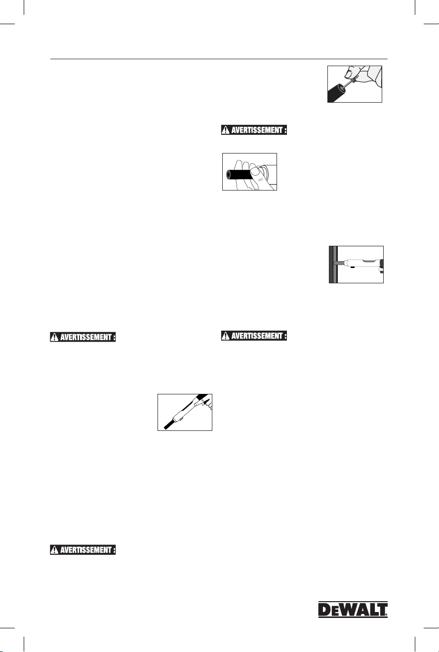
P2201
ModÈlE P2201 No dE Cat. DDF211022P
R2200
powder loads in the same container as the fasteners or
other hard objects.
4. Always store the powder loads in the containers provided
or in an enclosure provided for them. Never intermix the
various power levels. Keep them segregated in clearly
identified containers.
5.
Powder loads should never be used in firearms. They are normally
more powerful that the cartridges supplied with the firearms.
6.
Powder actuated tools and powder loads should always be stored
under lock and key. Tools must be unloaded when not in use.
Défaut de fonctionnement de l’outil
1. Si une cartouche ne se déchargeait pas au moment où
la détente de l’outil est enfoncée, il est nécessaire de
garder l’outil posé contre la surface de travail pendant
au moins 30 (trente) secondes au cas où la cartouche
se déchargerait en retard. Puis retirez lentement toute
la bande de cartouches puis jetez-la dans un pot rempli
d’eau ou rempli de tout autre liquide ininflammable. Ne
tentez jamais de forcer une cartouche hors de la chambre
de l’outil.
2. Ne disposez jamais d’une cartouche qui n’a pas été tirée
par l’outil en la jetant dans une poubelle.
3. Ne tentez jamais de décharger ou de démonter un outil
bloqué, coincé ou abîmé car une mauvaise manipulation
pourrait le décharger et toucher l’opérateur et/ou les
personnes à proximité. Un outil bloqué doit toujours être
dirigé vers un endroit non dangereux. Identifiez l’outil
endommagé et verrouillez-le. Appelez votre représentant
D
EWALT pour obtenir de l’aide.
Fonctionnement de
l’outil
comprendre l’ensemble des mesures de sécurité et de
formation dans ce manuel avant de commencer à utiliser
l’outil. (Vérifiez que l’outil n’est pas chargé, que le piston se
déplace librement dans le canon et qu’aucun objet étranger
ou attache ne se situe dans le canon.) Effectuez le test
quotidiennement avant d’utiliser l’outil.
Fonctionnement
1. Toujours pointer l’outil dans une
direction sûre loin de spectateurs
et l’opérateur. Faites glisser le
canon vers l’avant. Cela peut
être fait en claquant votre poignet. Le canon doit être tirée
complètement vers l’avant pour réinitialiser le piston de
la prochaine fixation. Perte de puissance peut résulter d’un
piston mal positionné.
2. Toujours charger la fixation avant de l’insérer charge de
poudre pour éviter les blessures à l’opérateur ou des tiers
en cas d’un déversement accidentel. Placez l’attache,
souligner, dans l’extrémité de la pièce de nez jusqu’à
ce que la douille cannelée s’adapte à l’intérieur. Ne pas
utiliser une force excessive lors de l’insertion de la fixation.
Si une force excessive est nécessaire, d’arrêter et de
déterminer pourquoi l’attache ne peut pas être insérée.
Corrigez le problème avant de poursuivre.
Assurez-vous de lire et de bien
3. Assurez-vous que la culasse est
clair. Insérer la charge de poudre
de départ avec le niveau de
puissance le plus bas. Si cette
charge n’a pas entièrement réglé la
fermeture, essayer le prochain niveau de puissance plus
élevé que le niveau approprié est trouvé.
attache accablante peut causer un danger pour la sécurité.
sécurité pour les mains et les doigts sont comme indiqué
dans le schéma. Les mains doivent jamais être placés à
l’avant de la bouche de l’outil ou la pièce de nez. Dans le
cas d’un déversement accidentel, le piston et / ou l’élément
de fixation peut passer à travers la main des opérateurs.
5. Une fois que l’outil est dans la
position fermée, la placer contre
la surface de travail. Tenez votre
outil fermement à deux mains et
appuyer complètement le baril.
Ensuite, appuyez sur la gâchette. Tenez toujours l’outil
perpendiculairement à la surface de travail. Tenez votre
outil fermement contre la surface de travail pour éviter le
recul excessif. Ne jamais appuyer sur l’outil contre tout,
sauf la surface de travail.
Au cours de conduite ou une
4. Tirez le canon tout le chemin du
retour pour fermer l’outil. Ne tentez pas
de fermer l’outil par exercer une force
sur le devant de la pièce de nez. Ne
placez jamais vos doigts ou les mains
sur la bouche douille. La position de
Dans le cas où la charge ne se
déclenche pas après la gâchette, continuer à tenir l’outil
enfoncé contre la surface de travail pendant au moins
trente (30) secondes dans le cas d’une décharge de charge
retardée. Puis retirez soigneusement la bande de charge
entière et la jeter dans un bidon d’eau ou un autre liquide
non inflammable. Ne jamais tenter de forcer ou soulever
une charge hors d’une chambre de l’outil. Ne jetez pas les
charges non cuites dans une poubelle.
6. Pour se préparer à la prochaine fixation, pointer l’outil
dans une direction sûre. Enclenchez le canon vers l’avant
comme à l’étape 1. Cette action sera éjecter la charge
de poudre passé et bien remettre le piston. Toujours
insérer une nouvelle fixation avant de charger la charge
de poudre dans la chambre. N’essayez pas de décharger
ou de démonter, un outil coincé ou cassé coincé comme
une mauvaise manipulation peut causer de s’acquitter et
l’opérateur et / ou spectateur grève. Un outil coincé doit
être pointée dans une direction sécuritaire en tout temps.
Marquer l’outil et l’enfermer. Appelez votre représentant
D
EWALT attaches pour une assistance appropriée.
Ne pas utiliser des attaches plus
de 3 po comme indiqué dans la section de sélection de
fermeture de ce manuel.
26
POW2273_manual_P2201_dewalt.indd 26 3/10/14 12:41 PM
Page 27
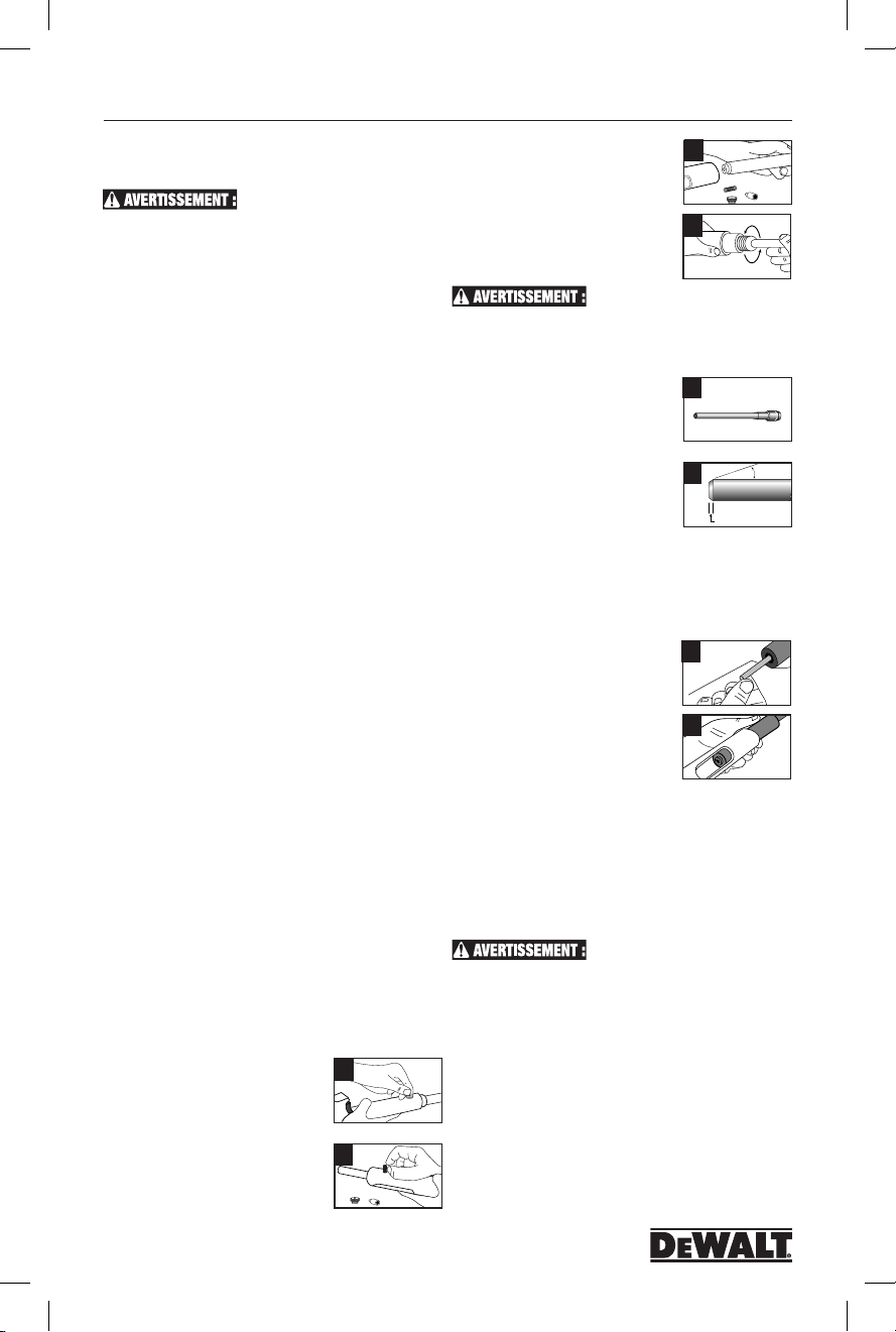
ModÈlE P2201 No dE Cat. DDF211022P
P2201
Maintenance et nettoyage
adéquats
N’EST PAS CHARGÉ. VÉRIFIEZ QUE L’OUTIL N’EST
PAS CHAUD AVANT DE LE DÉMONTER OU DE LE
NETTOYER.
Test de fonctionnement quotidie.
Vérifiez le fonctionnement de l’outil sans charger de
cartouche ou d’attache, en poussant l’outil contre la surface
de travail, en pressant sur la détente puis en relâchant la
pression sur l’outil. Faites ce même test à vide plusieurs fois
et vérifiez que les pièces de la culasse et du mécanisme de
mise à feu fonctionnent sans contrainte avant d’installer des
attaches avec l’outil.
Votre représentant autorisé DEWALT peut vous
aider lorsque vous démontez et nettoyez votre outil pour la
première fois.
Si vous rencontrez un problème lors du remontage de
l’outil, ou si vous avez un doute concernant l’usure d’une
pièce, appelez votre distributeur autorisé DEWALT.
Nettoyage
Toutes les pièces doivent être nettoyées à l’huile détergente
et avec les brosses métalliques fournies avec votre outil.
Nettoyez les accumulations de poussière à la brosse.
Après le nettoyage à l’huile, toutes les pièces doivent être
soigneusement séchées. Un excès d’huile attire la poussière
et la saleté. Portez des lunettes de protection lorsque vous
nettoyez l’outil. Le piston, le canon et la chambre à piston
doivent être soigneusement nettoyés quotidiennement pour
enlever tout excès de poussières. Vérifiez l’état du piston,
s’il est endommagé ou porte des traces d’usure ou de
déformation.
Pour garder cet outil en bon état, il est nécessaire de
le démonter entièrement et de le nettoyer si vous voyez
des résidus de poussières sur la culasse, ou si l’outil
semble manquer de puissance. Toutes les pièces doivent
être nettoyées à l’aide de pinceaux à huile et de brosses
métalliques. Enlevez toute trace de poussière et de débris.
Toutes les pièces doivent être soigneusement séchées après
les avoir nettoyées à l’huile.
Un entretien général doit être effectué tous les six mois ou
plus fréquemment selon la fréquence d’utilisation de l’outil.
Replacing or Repairing the Piston
Le piston est une pièce d’usure et doivent être
remplacées périodiquement. Les signes typiques d’un piston
usés sont: la rupture, de flexion ou poussent comme des
champignons. Avant l’entretien de l’outil assurez-vous qu’il
n’y a pas de charge de poudre dans l’outil. Faites preuve de
prudence et ne pas perdre ou endommager les parties de
l’outil.
1. Desserrer le bouchon sur la broche de remise à zéro
en tournant dans le sens antihoraire.
Retirer le bouchon de broche de
réinitialisation.
2. Tenir le corps en place, puis retirez
le ressort de broche de
réinitialisation et broches.
ASSUREZ-VOUS QUE L’OUTIL
1
2
3. Faites glisser le canon du récepteur
en le tirant vers l’avant. Si de la
saleté excessive est construit à
l’intérieur du récepteur, le nettoyer
avec une brosse métallique.
4. Dévisser la pièce de canon de nez
en tournant dans le sens
antihoraire. Tirer le piston vers
l’avant hors du canon.
Si un dispositif de serrage de l’étau
est utilisé pour retenir le canon, le canon protéger contre les
dommages.
5. Nettoyez le piston à l’aide d’une brosse métallique. Inspecter
pour bague usée ou endommagée piston, fin ébréchée,
ou de flexion. Appliquer du lubrifiant
sur la tige de piston pour minimiser
piston collage d’une condition
overdrive. Essuyez le piston sec.
6. Si une pointe de piston est
endommagé, il peut être raccourci
au maximum de 0,20 cm. L’extrémité
du piston doit être rainurée à plat et
à 90 degrés par rapport à la tige du
piston. Le chanfrein du piston doit également être réaffûté
comme indiqué. Piston broyage doit être effectué par du
personnel qualifié en utilisant l’équipement approprié.
Remontage:
7. Appuyer sur le piston dans le cylindre. Enfilez le nez dans
le canon et le serrer dans le sens
horaire jusqu’à ce que la main.
Assurez-vous que le nez est bien en
place.
8. Aligner la fente dans le cylindre, avec
l’ouverture de broche de remise à
zéro dans le fond du récepteur.
Insérez le canon dans le récepteur.
Insérez la broche de remise à zéro, et
réinitialiser broches printemps. Serrer
la réinitialisation bouchon de broche dans le sens horaire
jusqu’à ce qu’elle soit bien serrée et bien en place.
Lors du remontage de l’outil effectuez le test suivant.
Appuyer sur l’outil sur une surface plane, rigide et appuyer
sur la gâchette. L’ensemble de baril devrait glisser facilement
à l’intérieur du récepteur de l’outil. Le percuteur doit libérer
après que la gâchette a été tiré.
CE TEST DOIT ÊTRE EFFECTUÉ
SANS UNE BROCHE OU DE LA CHARGE DE POUDRE
DANS L’OUTIL.
3
4
5
6
7
8
10°
0.120"
27
POW2273_manual_P2201_dewalt.indd 27 3/10/14 12:41 PM
Page 28

P2201
ModÈlE P2201 No dE Cat. DDF211022P
#
Dépannage
Vérifiez toujours le manuel d’instructions pour savoir comment assembler correctement les différentes pièces
PROBLÊME CAUSE POSSIBLE SOLUTION
L’attache est trop enfoncée Le niveau de charge est trop élevé /
L’outil ne fonctionne pas L’outil ne s’enfonce pas complètement Voir la section ci-dessous « L’outil ne s’enfonce pas
L’outil ne s’enfonce pas
complètement
La puissance est réduite ou la
pénétration de l’attache est iné gale
Impossible d’insérer la bande
de cartouche dans l’outil
La bande de cartouches
n’avance pas qualifiée
La cartouche n’est pas tirée une
fois la détente pressée
La cartouche n’est pas tirée une
fois l’outil bien enfoncé et la
détente pressée
Impossible d’ouvrir l’outil ou
de l’utiliser
Le piston est bloqué en position
avancée
Le piston est ébréché ou
endommagé
Le guide du piston ne s’ouvre
pas facilement
Le guide du piston s’ouvre trop
facilement
le clou est trop court
Le matériau de base est mou Vérifiez la compatibilité du matériau de base
Le percuteur est endommagé Remplacez les pièces endommagées
L’éjecteur ou d’autres pièces de mise à feu
sont endommagées, les pièces sont mal
assemblées
Le canon n’est pas complètement tiré en avant
lorsque l’outil est actionné.
Le piston ou la rondelle de rétention du
piston sont usés ou endommagés
Chargement mal fait Insérez la bande en entrant sous la poignée de l’outil
Bande du mauvais calibre Utilisez la bande de cartouches adéquate
Guide du levier d’avancement usé Remplacez le guide du levier d’avancement. Cette tâche
L’outil n’est pas bien enfoncé Suivez la procédure de sécurité concernant les
La charge est déjà tirée Faites fonctionner l’outil
Cartouche non tirée Suivez la procédure de sécurité
Percuteur brisé Remplacez l’écrou du percuteur. Cette tâche doit être
Percuteur manquant ou brisé Remplacez l’écrou du percuteur. Cette opération doit
Nettoyage non adéquat Enlevez et remplacez le piston
Piston endommagé ou tordu Nettoyez soigneusement l’outil
Pièces brisées ou endommagées Identifiez l’outil avec l’avertissement « Outil défectueux - ne
Le piston a été poussé trop fort et est bloqué
contre l’axe de réinitialisation du piston
L’outil n’a pas été tenu perpendiculairement
à la surface de travail. Cela laisse le piston
s’éloigner de la tête du clou et finit par
endommager le piston
Le clip de retenue est tordu Enlevez et remplacez le clip de retenue
Accumulation de poussières Démontez et nettoyez l’outil
La butée de piston est endommagée Remplacez la butée de piston
Des matières étrangères sont coincées
entre le guide du piston et la
chambre à piston
Le ressort de la bille annulaire ou
annulaire en acier sont usés
Utilisez une cartouche de niveau de charge inférieur ou
un clou plus long
complètement »
Vérifiez l’état des pièces et vérifiez que l’assemblage
est bien fait
Le canon doit être complètement tiré pour bien réinitialiser
le piston
Remplacez le piston ou la rondelle de rétention du piston
doit être effectuée par une personne.
cartouches non tirées puis essayez d’enfoncer à nouveau
l’outil avant de presser sur la détente
effectuée par des personnes qualifiées.
être effectuée par des personnes qualifiée.
pas utiliser ». Placez-le dans un endroit fermé et contactez
votre représentant autorisé D
de l’assistance
Tapez le piston contre une surface dure
Réusinez le piston tel qu’illustré en page 11. Un réusinage
du piston ne peut être effectué que par des personnes
qualifiées.
Disassemble and remove foreign particles
Démontez et retirez les matières étrangères
EWALT pour obtenir
28
POW2273_manual_P2201_dewalt.indd 28 3/10/14 12:41 PM
Page 29

ModÈlE P2201 No dE Cat. DDF211022P
P2201
EXAMEN DE QUALIFICATION D’OPÉRATEUR DE L’OUTIL
#
NOM DE L’OPÉRATEUR DATE
ADRESSE PERSONNELLE
AGE DATE DE NAISSANCE
3
☐
Cochez la bonne réponse
Il est nécessaire de lire le manuel d’instructions avant
1
d’utiliser un pistolet de scellement à basse vélocité
de DEWALT.
Pour installer une attache dans du béton, quel est le
2
rapport entre la pénétration de l’attache et l’épaisseur
minimale du matériau de base?
☐1 fois ☐2 fois ☐3 fois
Lorsque vous utilisez un pistolet de scellement, vous
3
ne devez jamais poser la main :
☐ sur le corps de l’outil
☐ devant la bouche du canon de l’outil
☐ sur la poignée de l’outil
4 Pour déterminer la compatibilité d’un matériau de base,
utilisez l’attache comme un poinçon.
•Sil’attacheestémoussée,nel’installezpas;lematériau
est trop : ☐ mou ☐ dur ☐friable
•Sil’attachepénètrefacilement,nel’installezpas;le
matériau est trop : ☐ mou ☐ dur ☐friable
•Si l’attache se fissure ou se brise en éclats, ne
l’installezpas;lematériauesttrop:
☐ mou ☐ dur ☐friable
5 Pour quelle(s) raison(s) une application peut-elle être
non sécuritaire pour un pistolet de scellement
☐ le matériau de base est mou
☐ la cartouche n’est pas adaptée
☐ l’attache est posée trop proche d’une
bordure non soutenue
☐ l’outil est dysfonctionnel
☐ l’attache est installée dans une partie fissurée
☐ fissurée trou pré-percé
☐ toutes les réponses ci-dessus
6 Parmi les matériaux de construction suivants, quels
sont ceux qui ne sont pas adaptés pour une attache à
scellement à cartouche?
☐ plaque de plâtre ☐ bois ☐ fibre de verre
☐ tôle ☐ toutes les réponses ci-dessus
.
☐Vrai ☐ Faux
7 Lorsque vous réfléchissez à la sécurité dans une
application particulière, vous devez réfléchir :
☐ au matériau de base
☐ au niveau de charge de la cartouche
☐ à la sécurité de l’opérateur
☐ là la sécurité des personnes à proximité et à celle
des compagnons de travail
☐ toutes les réponses ci-dessus
8 La procédure adéquate pour charger l’outil est
d’insérer d’abord l’attache, puis la cartouche. L’attache
doit toujours être insérée dans l’outil avant la cartouche
☐ Vrai ☐ Faux
9 Parmi ces matériaux, lequel peut être utilisé pour in-
staller une attache à l’aide d’un pistolet de scellement?
☐ béton coulé ☐ bloc creux
☐ acier trempé ☐ brique vernissée
10 Dans du béton, quelle est la distance de bordure
minimale à laquelle une attache ne doit jamais être
installée si la bordure n’est pas soutenue :
☐ 1/2po ☐ 1-1/2po ☐3po
11 La déformation en forme d’hameçon est un cas
qui peut arriver lorsqu’une attache à scellement à
cartouche frappe un morceau d’agrégat dur ou du béton
trèsdur;l’attacheseplieetressortdumatériau.Un
tel cas peut causer des blessures graves ou mortelles.
☐Vrai ☐Faux
12 Placer la main sur la bouche du canon d’un outil
chargé est dangereux car cela peut provoquer des
blessures graves si le piston est percuté trop
fortement ou si l’attache est éjectée de l’outil en cas
d’une décharge accidentelle. ☐Vrai ☐Faux
13 Un piston frappé trop fortement est dû à une charge
trop forte ou à un déchargement de l’outil contre une
surface molle. ☐Vrai ☐Faux
14 Les outils dysfonctionnels ne doivent pas être utilisés
et doivent être immédiatement mis hors service.
☐Vrai ☐Faux
NOM DE L’ENTERPRISE
ADRESSE DE L’ENTREPRISE
NUMÉRO DE TÉLÉPHONE DE L’ENTREPRISE
SIGNATURE DATE
15 Après avoir effectué un test au pointeau, la meilleure
méthode pour vérifier le matériau de base est
d’installer plusieurs attaches en utilisant le niveau de
charge le plus faible. ☐Vrai ☐Faux
16 L’opérateur et les personnes situées à proximité n’ont
pas besoin de porter des lunettes de sécurité et des
casques anti-bruit lorsque l’outil est en fonction.
☐Vrai ☐Faux
17 Un pistolet de scellement ne peut pas être utilisé en
toute sécurité dans une atmosphère explosive ou
inflammable. ☐Vrai ☐Faux
18 Indiquez le niveau de charge (1-6) correspondant à
chaque couleur de cartouche.
Rouge___ Brun ___ Vert ___ Jaune___
Gris ___ Violet ___
19 Le niveau de charge le plus faible doit être utilisé
pour installer la première attache. ☐Vrai ☐Faux
20 Il est possible d’installer des attaches dans des
surfaces d’acier soudées. ☐Vrai ☐Faux
P2201
•La procédure adéquate si une cartouche n’est pas
éjectée est de tenir l’outil contre la surface de travail
et d’attendre 30 secondes, puis de procéder comme
indiqué dans le manuel d’instructions. ☐Vrai ☐Faux
•Les cartouches de D
ment P2201 sont des cartouches cannelées courtes
de calibre .22, de conicité A, à percussion annulaire.
Aucune autre cartouche ne peut être utilisée dans cet
outil ☐Vrai ☐Faux
•L’opérateur ne devrait jamais comprimer le pistolet de
scellement P2201 ou tout autre pistolet de scellement
contre son corps. ☐Vrai ☐Faux
•Si l’amortisseur de recul du piston est déformé, il est
possible de le retirer et d’utiliser le pistolet de scellement P2201 sans aucun amortisseur de recul.
☐Vrai ☐Faux
EWALT pour le pistolet de scelle-
LICENCE ET ACTIVATION DE LA GARANTIE
LE PISTOLET DE SCELLEMENT P2201 SET GARANTI POUR 3 ANS à PARTIR DE LA DATE D’ACHAT SUR LES DÉFAUTS DE FABRICATION.
Je certifie avoir lu et compris l’intégralité du manuel d’instructions du pistolet de scellement P3500 et avoir passé l’examen de l’opérateur. Je comprends
l’importance des procédures de sécurité et je comprends que le fait de ne pas lire, comprendre ou suivre adéquatement tous les règlements et tous les
avertissements liés à l’utilisation sécuritaire des pistolets de scellement peut provoquer des blessures graves ou mortelles à l’opérateur de l’outil ainsi qu’aux
personnes situées à proximité. J’accepte de suivre tous les règlements et toutes les règles concernant l’utilisation des pistolets de scellement.
(Ecrire en caractères d’imprimerie)
GARNITURE LONG DES POINTILLÉS, METTRE DANS UNE ENVELOPPE, ADRESSE ET COMME INDIQUE AFFRANCHIR
LE NUMÉRO DE SÉRIE DE MON OUTIL EST LE :
VEUILLEZ ENVOYER MA LICENCE D’OPÉRATEUR À L’ADRESSE SUIVANTE :
NOM :
ADDRESSE :
VILLE : PROVINCE CODE POSTAL TÉLÉPHONE
ENVOYER À L’ADRESSE : Tool License Coordinator • DEWA LT, Inc.• 2 Powers Lane, Brewster, NY 10509
29
POW2273_manual_P2201_dewalt.indd 29 3/10/14 12:41 PM
Page 30

P2201
Model P2201 Modelo P2201 ModÈle P2201
30
POW2273_manual_P2201_dewalt.indd 30 3/10/14 12:41 PM
Page 31

P2201
Model P2201 Modelo P2201 ModÈle P2201
31
POW2273_manual_P2201_dewalt.indd 31 3/10/14 12:41 PM
Page 32

P2201
Model P2201 Modelo P2201 ModÈle P2201
32
POW2273_manual_P2201_dewalt.indd 32 3/10/14 12:41 PM
 Loading...