

Page 1

(OCTOBER16) Part No. 200-2894-B DXCMPA1982054 Copyright © 2012, 2013, 2014, 2015,
If you have questions or comments, contact us.
Pour toute question ou tout commentaire, nous contacter.
Si tiene dudas o comentarios, contáctenos.
1-888-895-4549 • www.dewalt.com
INSTRUCTION MANUAL
MAT Industries, LLC, Long Grove, IL 60047
GUIDE D'UTILISATION
MANUAL DE INSTRUCCIONES
2016 DEWALT
INSTRUCTIVO DE OPERACIÓN, CENTROS DE SERVICIO Y
PÓLIZA DE GARANTÍA. ADVERNTENCIA: LÉASE ESTE
INSTRUCTIVO ANTES DE USAR EL PRODUCTO.
DXCMPA1982054
Single Stage, Belt Drive, Electric Air Compressors
Compresseurs d’air électriques à un étage à entraînement par courroie
Compresores eléctricos de aire, de una sola etapa y accionamiento por correa
Page 2
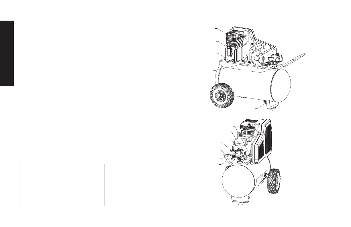
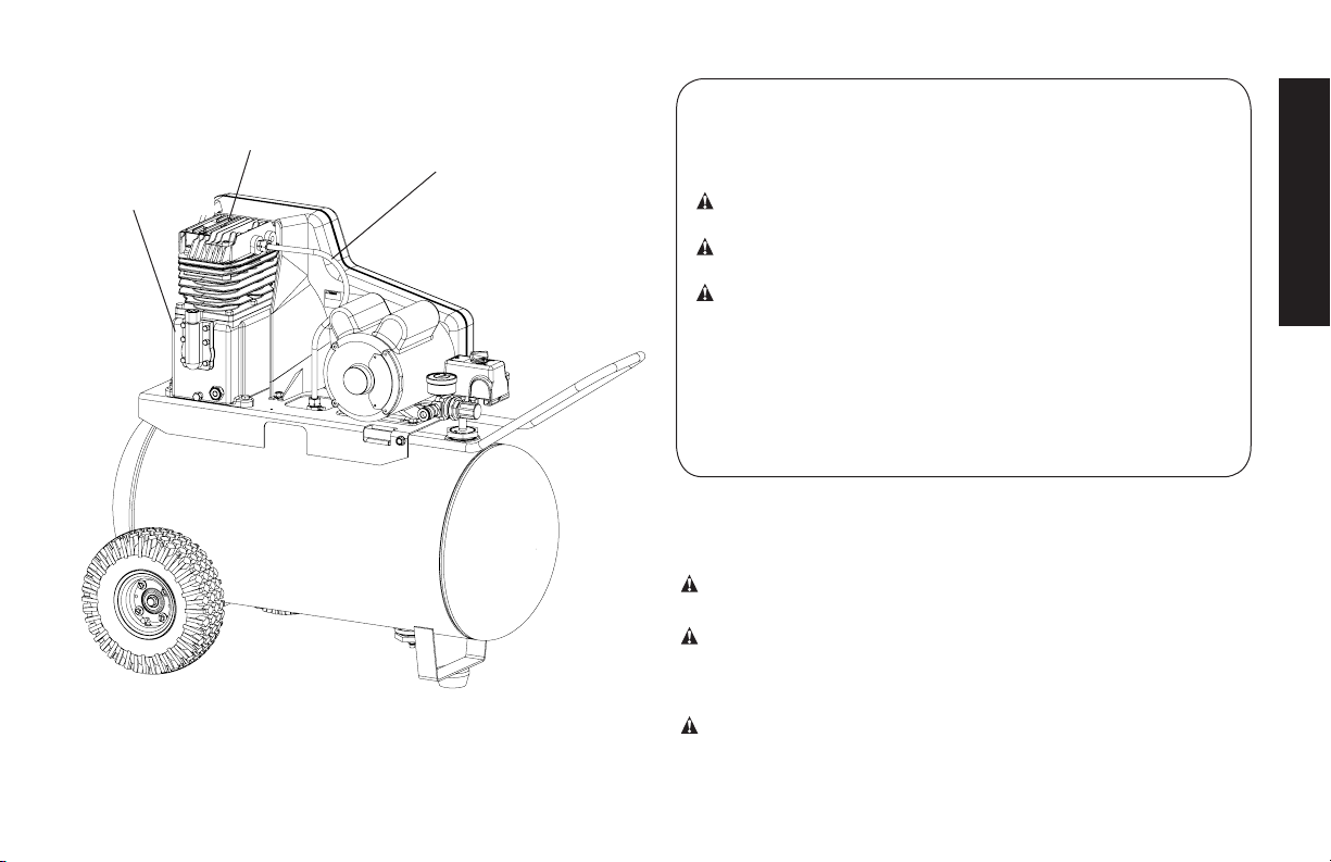
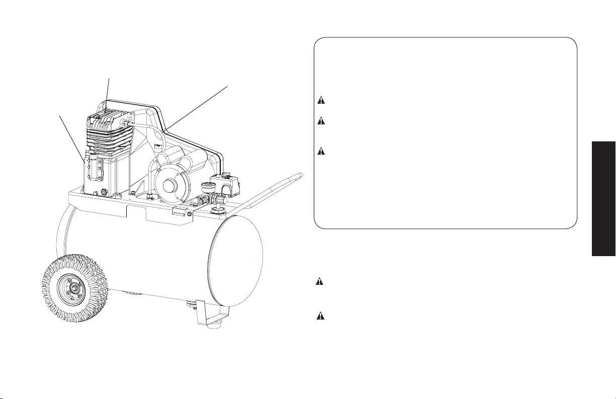
Air Compressor
A. Pump Air Intake Filter
B. Auto(-)/Off(O) Switch
C. Air Tank Pressure Gauge
D. Regulated Pressure Gauge
E. Pressure Regulator
F. Air Outlet
English
G. Safety Valve
H. Air Tank Drain Valve
I. Pump Oil Fill Plug
J. Pump Oil Drain Plug
K. Check Valve
L. Quick Connect
Pump Specications
2 Cylinder
Single Stage
Oil Lubricated
Cast iron crankcase, cylinder, and aluminum head
Weight: 41 lbs. (18.6 kg.)
Oil Capacity: 16 oz. (473 mL)
A
I
J
K
H
C
G
B
D
F
FIG. 1
Specications
MODEL DXCMPA1982054
WEIGHT 165 lbs. (75 kg)
HEIGHT 33.625”
WIDTH 34.188”
AIR TANK CAPACITY 20 gallons (75,7 liters)
APPROX. BLOW OFF PRESSURE
175 psi
L
E
2
Page 3
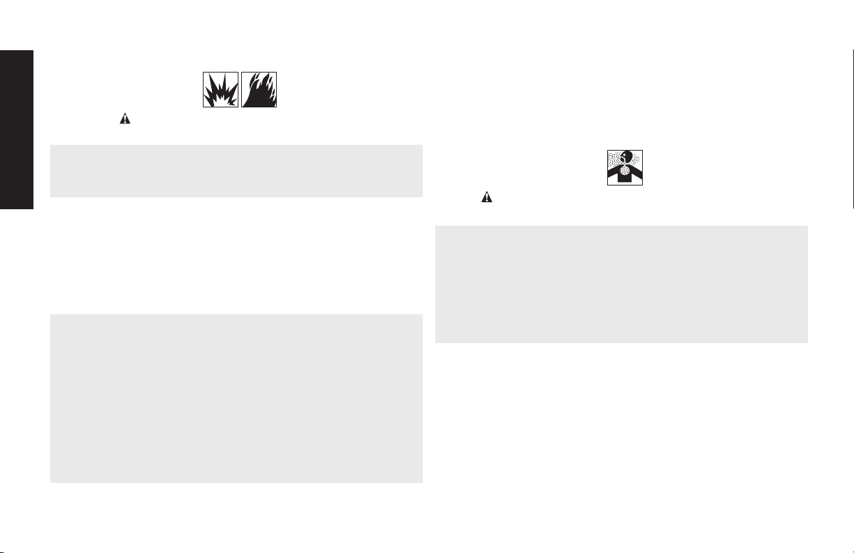
Hot Surfaces
COMPRESSOR CYLINDER
& HEAD
PUMP
CRANKCASE
OUTLET TUBE
FIG. 2
Denitions: Safety Guidelines
The definitions below describe the level of severity
for each signal word. Please read the manual and pay attention
to these symbols.
DANGER: Indicates an imminently hazardous situation
which, if not avoided, will result in death or serious injury.
WARNING: Indicates a potentially hazardous situation
which, if not avoided, could result in death or serious injury.
CAUTION: Indicates a potentially hazardous situation which,
if not avoided, may result in minor or moderate injury.
NOTICE: Indicates a practice not related to personal injury
which, if not avoided, may result in property damage.
IF YOU HAVE ANY QUESTIONS OR COMMENTS ABOUT
THIS OR ANY DeWALT TOOL, CALL US TOLL FREE AT:
1-888-895-4549
Important Safety Instructions
WARNING: Do not operate this unit until you read this instruction
manual for safety, operation and maintenance instructions.
WARNING: CALIFORNIA PROPOSITION 65 WARNING: This
product contains chemicals known to the State of California to cause
cancer, and birth defects or other reproductive harm. Wash hands
after handling.
WARNING: Some dust contains chemicals known to the State of
California to cause cancer, birth defects or other reproductive harm
such as asbestos and lead in lead based paint.
English
3
Page 4
SAVE THESE INSTRUCTIONS
DANGER: RISK OF EXPLOSION OR FIRE
WHAT CAN HAPPEN HOW TO PREVENT IT
• It is normal for electrical con-
English
tacts within the motor and
pressure switch to spark.
• If electrical sparks from compressor come into contact
with flammable vapors, they
may ignite, causing fire or
explosion.
• Restricting any of the compressor ventilation openings
will cause serious overheating and could cause fire.
• Always operate the compressor in a well ventilated area
free of combustible materials,
gasoline, or solvent vapors.
• If spraying flammable materials, locate compressor at
least 20' (6.1m) away from
spray area. An additional
length of air hose may be
required.
• Store flammable materials in
a secure location away from
compressor.
• Never place objects against
or on top of compressor.
• Operate compressor in an
open area at least 12”
(30.5 cm) away from any wall
or obstruction that would
restrict the flow of fresh air to
the ventilation openings.
• Operate compressor in a
clean, dry well ventilated
area. Do not operate unit in
any confined area. Store
indoors.
• Unattended operation of this
product could result in personal injury or property damage. To reduce the risk of
fire, do no allow the compressor to operator unattended
DANGER: RISK TO BREATHING (ASPHYXIATION)
WHAT CAN HAPPEN HOW TO PREVENT IT
• The compressed air directly
from your compressor is not
safe for breathing. The air
stream may contain carbon
monoxide, toxic vapors,
or solid particles from the
air tank. Breathing these
contaminants can cause
serious injury or death.
• Exposure to chemicals
in dust created by
power sanding, sawing,
grinding, drilling and other
construction activities may
be harmful.
• Sprayed materials such as
paint, paint solvents, paint
remover, insecticides, weed
killers, may contain harmful
vapors and poisons.
• Always remain in attendance
with the product when it is
operating.
• Always turn off and unplug
unit when not in use.
• Never use air obtained directly
from the compressor to supply
air for human consumption.
The compressor is not
equipped with suitable filters
and in-line safety equipment
for human consumption.
• Work in an area with good
cross ventilation. Read and
follow the safety instructions
provided on the label or
safety data sheets for the
materials you are spraying.
Always use certified safety
equipment: NIOSH/OSHA
respiratory protection or
properly fit ting face mask
designed for use with your
specific application.
4
Page 5

DANGER: RISK OF BURSTING
Air Tank: On February 26, 2002, the U.S. Consumer Product Safety
Commission published Release # 02-108 concerning air compressor tank safety:
Air compressor receiver tanks do not have an infinite life. Tank life is
dependent upon several factors, some of which include operating
conditions, ambient conditions, proper installations, field modifications, and the level of maintenance. The exact effect of these factors on air receiver life is difficult to predict.
If proper maintenance procedures are not followed, internal corrosion to the inner wall of the air receiver tank can cause the air tank
to unexpectedly rupture allowing pressurized air to suddenly and
forcefully escape, posing risk of injury to consumers.
Your compressor air tank must be removed from service by the end
of the year shown on your tank warning label.
The following conditions could lead to a weakening of the air tank,
and result in a violent air tank explosion:
WHAT CAN HAPPEN HOW TO PREVENT IT
• Failure to properly drain
condensed water from air
tank, causing rust and thinning
of the steel air tank.
• Modifications or attempted
repairs to the air tank.
• Drain air tank daily or after each
use. If air tank develops a leak,
replace it immediately with
a new air tank or replace the
entire compressor.
• Never drill into, weld or make
any modifications to the air
tank or its attachments. Never
attempt to repair a damaged or
leaking air tank. Replace with a
new air tank.
• Unauthorized modifications to
the safety valve, or any other
components which control air
tank pressure.
Attachments & Accessories:
• Exceeding the pressure rating
of air tools, spray guns, air
operated accessories, tires
and other inflatables can
cause them to explode or
fly apart, and could result in
serious injury.
Tires:
• Over inflation of tires could
result in serious injury and
property damage.
• The air tank is designed
to withstand specific
operating pressures. Never
make adjustments or parts
substitutions to alter the factory
set operating pressures.
• Follow the equipment
manufacturers
recommendation and never
exceed the maximum allowable
pressure rating of attachments.
Never use compressor to
inflate small low pressure
objects such as children’s toys,
footballs, basketballs, etc.
• Use a tire pressure gauge to
check the tires pressure before
each use and while inflating
tires; see the tire sidewall for
the correct tire pressure.
NOTE: Air tanks, compressors
and similar equipment used to
inflate tires can fill small tires
very rapidly. Adjust pressure
regulator on air supply to no
more than the rating of the
tire pressure. Add air in small
increments and frequently use
the tire gauge to prevent over
inflation.
English
5
Page 6

DANGER: RISK OF INJURY OR PROP ER TY DAMAGE WHEN
WHAT CAN HAPPEN HOW TO PREVENT IT
• Oil can leak or spill and could
English
result in fire or breathing
hazard; serious injury or
death can result. Oil leaks will
damage carpet, paint or other
surfaces in vehicles or trailers.
TRANSPORTING OR STORING
• Always place compressor
on a protective mat when
transporting to protect against
damage to vehicle from leaks.
Remove compressor from
vehicle immediately upon
arrival at your destination.
Always keep compressor level
and never lie on its side.
6
Page 7

WARNING: RISK OF HOT SURFACES
WHAT CAN HAPPEN HOW TO PREVENT IT
• Touching exposed metal such
as the compressor head or
outlet tubes, can result in
serious burns.
WARNING: RISK OF ELECTRICAL SHOCK
WHAT CAN HAPPEN HOW TO PREVENT IT
• Your compressor is powered
by electricity. Like any other
electrically powered device,
if it is not used properly it
may cause electric shock.
• Never touch any exposed
metal parts on compressor
during or immediately after
operation. Compressor will
remain hot for several minutes
after operation
• Do not reach around
protective shrouds or attempt
maintenance until unit has
been allowed to cool.
• Never operate the compressor outdoors when it is raining or in wet conditions.
• Never operate compressor with protective covers
removed or damaged.
• Repairs attempted by
unqualified personnel can
result in serious injury or
death by electrocution.
• Electrical Grounding:
Failure to provide adequate
grounding to this product
could result in serious injury
or death from electrocution. Refer to Grounding
Instructions paragraph in
the Installation section.
• Any electrical wiring or
repairs required on this
product should be performed by authorized service center personnel in
accordance with national
and local electrical codes.
• Make certain that the electrical circuit to which the
compressor is connected
provides proper electrical
grounding, correct voltage
and adequate fuse protection.
English
7
Page 8
WARNING: RISK OF UNSAFE OPERATION
WHAT CAN HAPPEN HOW TO PREVENT IT
• Unsafe op er a tion of your air
English
compressor could lead to se rious in ju ry or death to you or
others.
• Review and understand all
instructions and warnings in
this manual.
• Be come fa mil iar with the op era tion and con trols of the air
compressor.
• Keep operating area clear of all
persons, pets, and obstacles.
• Keep chil dren away from the air
compressor at all times.
• Do not operate the product
when fatigued or under the
influence of alcohol or drugs.
Stay alert at all times.
• Never defeat the safety fea tures
of this prod uct.
• Equip area of operation with a
fire extinguisher.
• Do not op er ate machine with
missing, broken, or un au thorized parts.
• Never stand on the
compressor.
WARNING: RISK FROM MOVING PARTS
WHAT CAN HAPPEN HOW TO PREVENT IT
• Moving parts such as the
pulley, flywheel, and belt can
cause serious injury if they
come into contact with you or
your clothing.
• Attempting to operate
compressor with damaged or
missing parts or attempting
to repair compressor with
protective shrouds removed
can expose you to moving
parts and can result in serious
injury.
• Never operate the compressor
with guards or covers which are
damaged or removed.
• Keep your hair, clothing and
gloves away from moving parts.
Loose clothes, jewelry or long
hair can be caught in moving
parts.
• Air vents may cover moving
parts and should be avoided as
well.
• Any repairs required on this
product should be performed
by a DeWALT factory service
center or a DeWALT authorized
service center.
8
Page 9
WARNING: RISK OF
WHAT CAN HAPPEN HOW TO PREVENT IT
• Serious injury can result from
attempting to lift too heavy an
object.
CAUTION: RISK FROM NOISE
WHAT CAN HAPPEN HOW TO PREVENT IT
• Under some conditions and
duration of use, noise from
this product may contribute to
hearing loss.
INJURY FROM LIFTING
• The compressor is too heavy
to be lifted by one person.
Obtain assistance from others
before lifting.
• Always wear certified safety
equipment: ANSI S12.6
(S3.19) hearing protection.
SAVE THESE INSTRUCTIONS FOR FUTURE
USE
Know Your Air Compressor
READ THIS OWNER’S MANUAL AND SAFETY RULES BEFORE
OPERATING YOUR UNIT. Compare the illustrations with your
unit to familiarize yourself with the location of various controls
and adjustments. Save this manual for future reference.
FEATURES
AUTO (-) / OFF (O) SWITCH
Place this switch (B) in the AUTO (-) position to
provide automatic power to the pressure switch
and OFF(O) to remove power at the end of each
use. NOTE: ALWAYS ensure the switch (B) is in the
OFF (O) position before removing or replacing
pressure switch cover.
PRESSURE SWITCH
The pressure switch (B) automatically starts the motor when the air
tank pressure drops below the factory set cut-in pressure. It stops
the motor when the air tank pressure reaches the factory set cut-out
pressure.
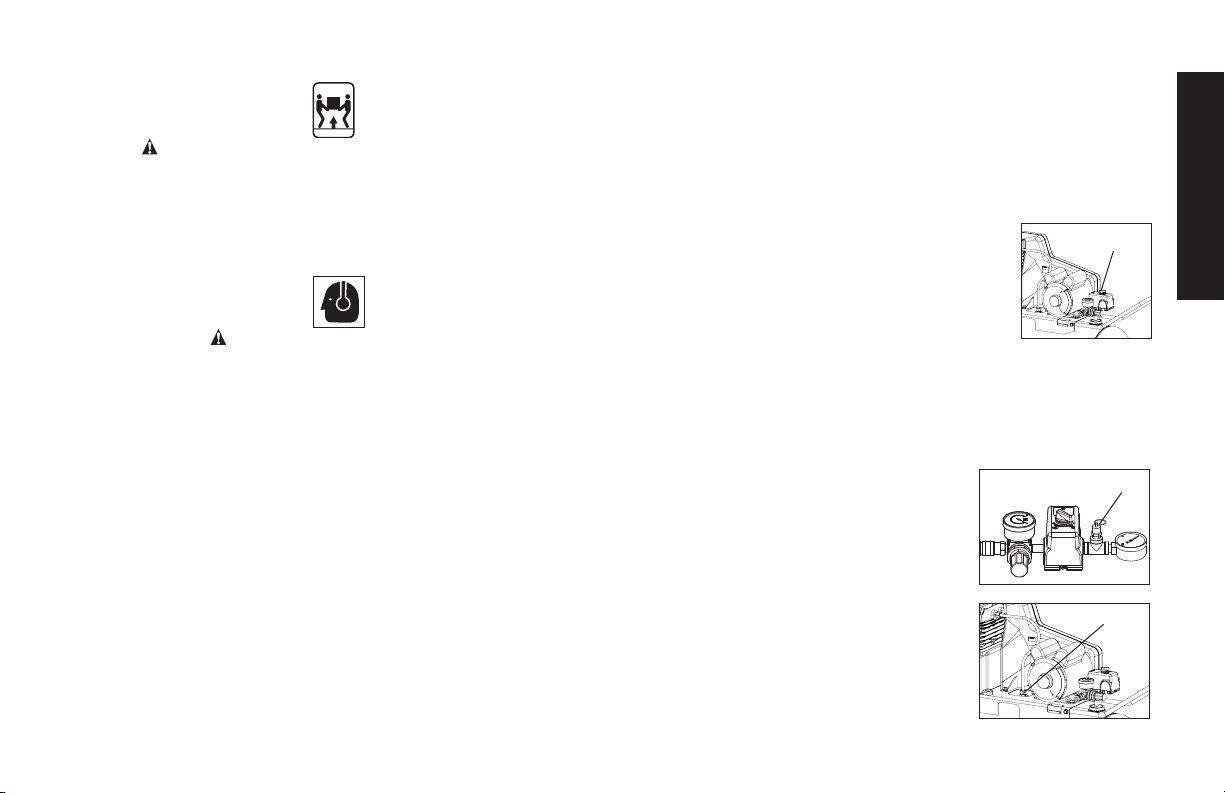
SAFETY VALVE
This valve (G) is designed to prevent system
failures by relieving pressure from the system
when the compressed air reaches a predetermined level. The valve is preset by the manufacturer and must not be removed or modified
in any way.
CHECK VALVE
When the air compressor is operating, the
check valve (K) is open, allowing compressed
air to enter the air tank. When the air compressor
B
G
K
English
9
Page 10
reaches cut-out pressure, the check valve closes, allowing air
pressure to remain inside the air tank.
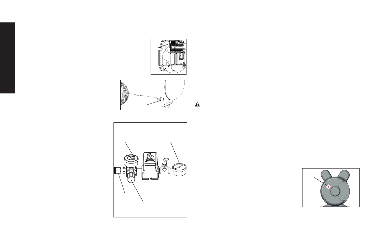
AIR INTAKE FILTER
The filter (A) is designed to clean air entering the
A
pump. To ensure the pump continually receives a
clean, cool, and dry air supply the filter must always
be clean and the filter intake must be free from
English
obstructions.
AIR TANK DRAIN VALVE
The drain valve (H) is located at the base
of the air tank and is used to drain
condensation at the end of each use.
See Draining Air Tank under
H
Maintenance.
REGULATED PRESSURE GAUGE
The regulated pressure gauge (D)
indicates the air pressure available at
the outlet side of the regulator. This
D
pressure is controlled by the regulator
and is always less or equal to the air
tank pressure.
TANK PRESSURE GAUGE
The tank pressure gauge (C) indicates
the reserve air pressure in the tank.
UNIVERSAL QUICK CONNECT
BODY
The universal quick connect body (L)
L
E
accepts the three most popular styles
of quick connect plugs: Industrial,
automotive, and ARO. One hand push-to-connect operation makes
connections simple and easy.
REGULATOR
The regulator knob (E) controls the air pressure coming from the air
tank.
To Adjust Regulator:
1. Pull regulator knob (E) out.
2. Turn knob clockwise to increase regulated pressure and
counter-clockwise to decrease regulated pressure.
3. When desired pressure is shown on the regulated pressure
gauge push knob in to lock.
WARNING: Risk of Bursting. Too much air pressure causes a
hazardous risk of bursting. Check the manufacturer’s maximum
pressure rating for air tools and accessories. The regulator outlet
pressure must never exceed the maximum pressure rating.
AIR COMPRESSOR PUMP
C
The pump compresses air into the air tank. Working air is not available
until the compressor has raised the air tank pressure above that
required at the air outlet.
MOTOR OVERLOAD PROTECTOR
The motor has a thermal overload protector.
If the motor overheats for any reason, the
overload protector will shut off the motor. The
M
motor must be allowed to cool down before
restarting. To restart:
1. Set the Auto/Off switch to OFF (O)
and unplug unit.
2. Allow the motor to cool.
3. Depress the red reset button (M) on the motor.
10
Page 11
4. Plug the power cord into the correct branch circuit receptacle.
5. Set the Auto/Off switch to AUTO (-).
INSTALLATION
Assembly (Fig. 1)
Unpack the air compressor. Inspect the unit for damage. If the
unit has been damaged in transit, contact the carrier and
complete a damage claim. Do this immediately because there
are time limitations to damage claims.
The carton should contain:
• air compressor
• operator and parts manuals
Check the compressor’s serial label to ensure that you have
received the model ordered, and that it has the required pressure
rating for its intended use.
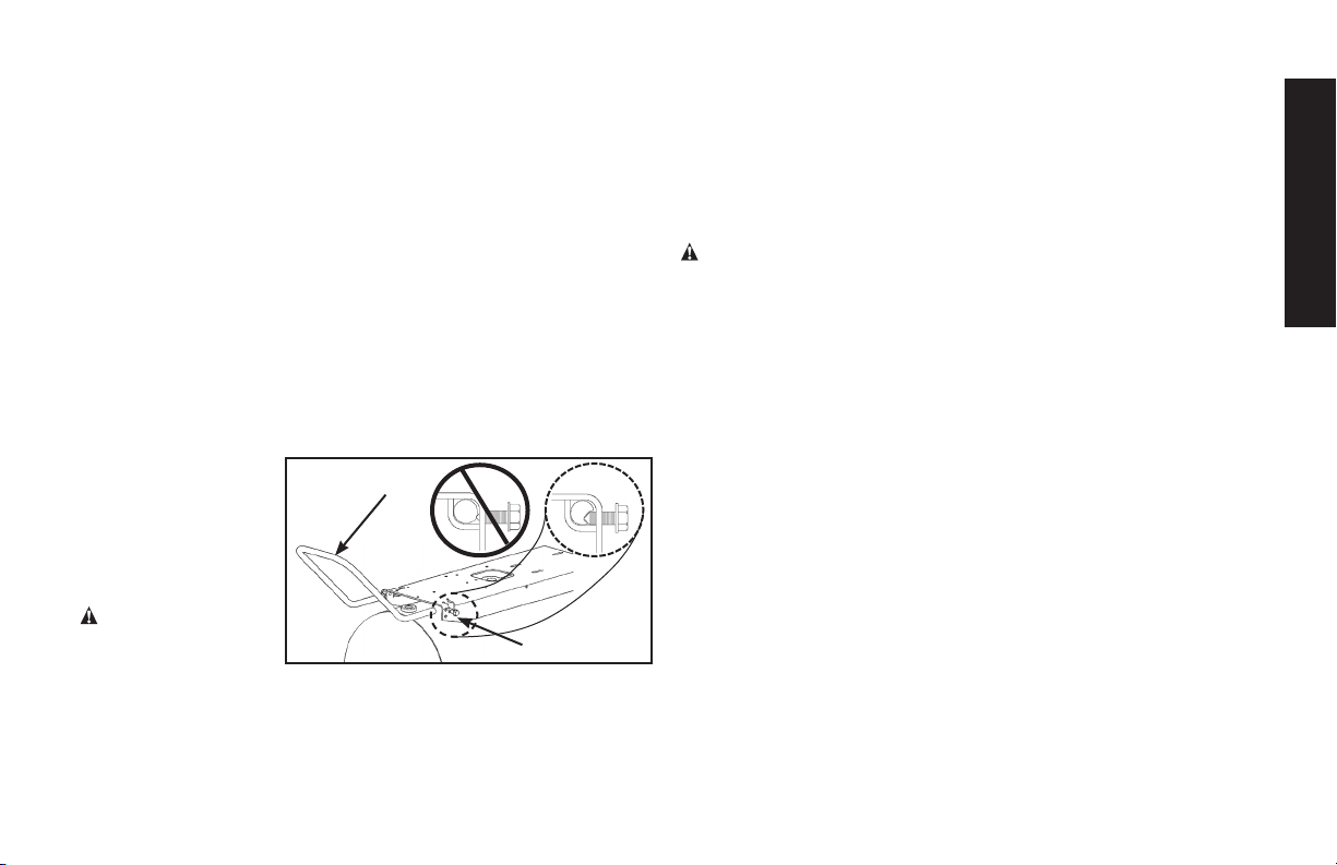
INSTALLING HANDLE
1. Insert end of handle
(N) into the base.
2. Tighten the bolts
(O)(provided)
against the base.
INSTALLING HOSES
WARNING: Risk
of unsafe operation.
Firmly grasp hose in
hand when installing or disconnecting to prevent hose whip.
1. Ensure regulated pressure gauge reads 0 psi.
2. Apply sealant tape to hose threads.
3. Assemble hose to air outlet (F). IMPORTANT: Do not assemble
N
O
splitters directly to the air outlet (F).
NOTE: Assembling quick connect bodies (L) to air outlet (F)
and quick connect plugs to hose ends make connecting and
disconnecting hoses simple and easy. Quick connect bodies and
plugs are available for purchase from your local dealer or authorized
service center.
DISCONNECTING HOSES
WARNING: Risk of unsafe operation. Firmly grasp hose in hand
when installing or disconnecting to prevent hose whip.
1. Ensure regulated pressure gauge reads 0 psi.
2. Remove hose from air outlet (F).
Lubrication and Oil
AIR COMPRESSOR
The air compressor pump was filled WITH oil at the manufacturer.
Check air compressor pump oil level before operating unit. See
Compressor Pump Oil under Maintenance.
Compatibility
Air tools and accessories that are run off the compressor must be
compatible with petroleum based products. If you suspect that a
material is not compatible with petroleum products, an air line filter
for removal of moisture and oil vapor in compressed air is required.
NOTE: Always use an air line filter to remove moisture and oil vapor
when spraying paint.
Location
• Locate the air compressor in a clean, dry, and well ventilated
area.
• Located the air compressor at least 12” (30.5 cm) away from
the wall or other obstructions that will interfere with the flow of
air.
English
11
Page 12
• Locate the air compressor as close to the main power supply
as possible to avoid using long lengths of electrical wiring.
NOTE: Long lengths of electrical wiring could cause power loss
to the motor.
• The air filter must be kept clear of obstructions which could
reduce air flow to the air compressor.
HUMID AREAS
English
In frequently humid areas, moisture may form in the pump and
produce sludge in the oil, causing running parts to wear out
prematurely. Excessive moisture is especially likely to occur if
the unit is located in an unheated area that is subject to large
temperature changes. Two signs of excessive humidity are external
condensation on the pump when it cools down and a “milky”
appearance in compressor oil. You may be able to prevent
moisture from forming in the pump by increasing ventilation or
operating for longer intervals.
Wiring Instructions
WARNING: Improper electrical installation of this product
may void its warranty and your fire insurance. Have circuit wiring
performed by qualified personnel such as a licensed electrician who
is familiar with the current national electrical code and any prevailing
local electrical codes.
WARNING: Risk of electrical shock. Improper electrical grounding
can result in electrical shock. The wiring should be done by a
qualified electrician.
A qualified electrician needs to knows the following before wiring:
1. The amperage rating of the electrical box should be adequate.
Refer to the Specifications, in the parts manual, for this
information.
2. The supply line should have the same electrical characteristics
(voltage, cycle, phase) as the motor. Refer to the motor
nameplate, on side of motor, for this information.
NOTE: The wiring used must be rated for the motor nameplate
voltage, plus or minus 10%. Refer to local codes for recommended
wire sizes, correct wire size, and maximum wire run; undersize wire
causes high amp draw and overheating to the motor.
WARNING: Risk of electrical shock. Electrical wiring must
be located away from hot surfaces such as manifold assembly,
compressor outlet tubes, heads, or cylinders.
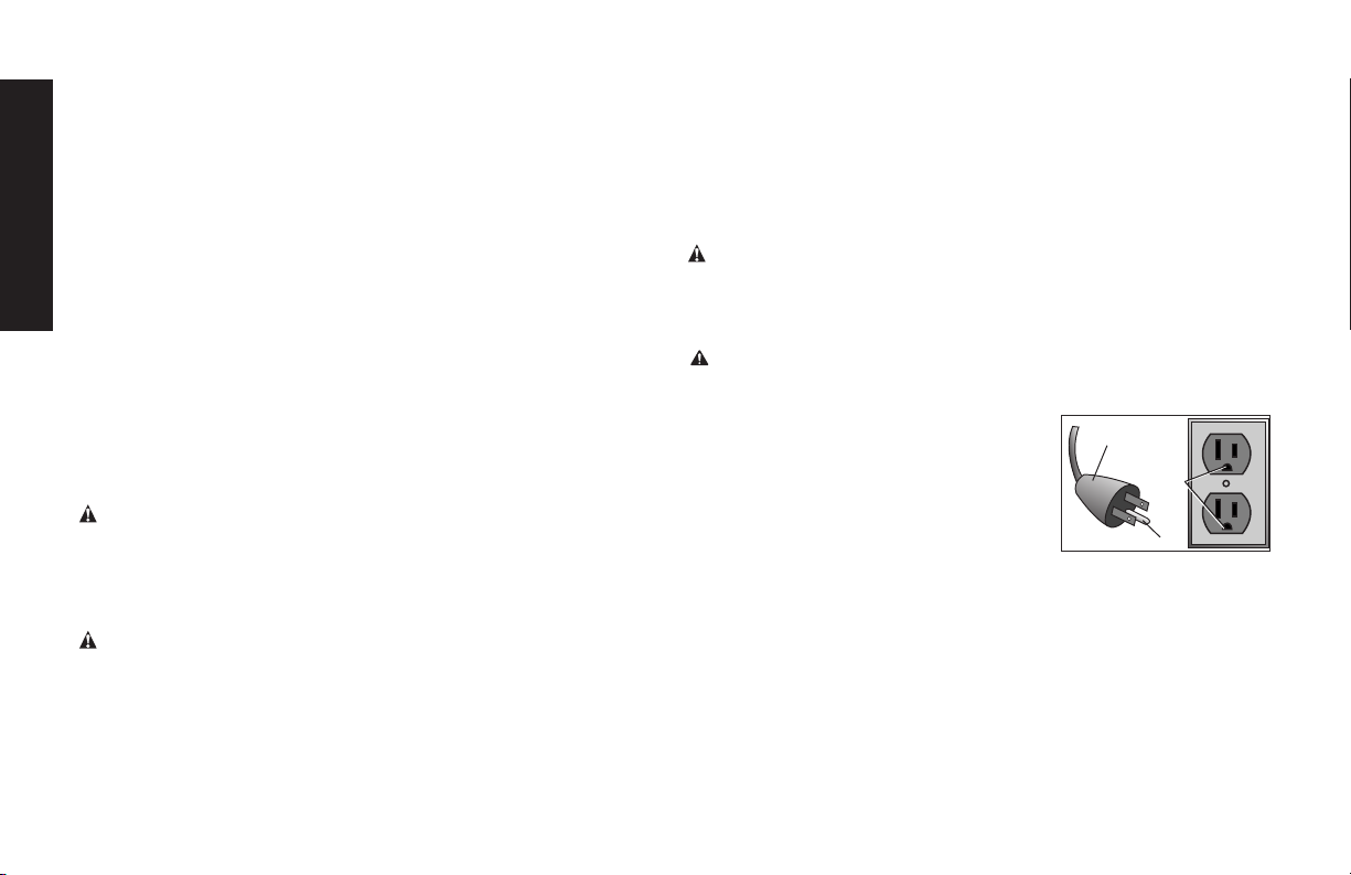
Grounding Instructions
WARNING: Risk of electrical shock. In the event of a short circuit,
grounding reduces the risk of shock by providing an escape wire for
the electric current. This air compressor must be properly grounded.
The portable air compressor is equipped
with a cord having a grounding wire with an
appropriate grounding plug.
1. The cord set and plug (R) with this
unit contains a grounding pin (P). This
plug MUST be used with a grounded
outlet (Q).
IMPORTANT: The outlet being used must be installed and grounded
in accordance with all local codes and ordinances.
2. Ensure the outlet being used has the same configuration as the
grounded plug. DO NOT USE AN ADAPTER.
3. Inspect the plug and cord before each use. Do not use if there
are signs of damage.
4. If these grounding instructions are not completely understood,
or if in doubt as to whether the compressor is properly grounded,
have the installation checked by a qualified electrician.
R
Q
P
12
Page 13

DANGER: Risk of electrical shock. IMPROPER GROUNDING
CAN RESULT IN ELECTRICAL SHOCK.
• Do not modify the plug provided. If it does not fit the available
outlet, a correct outlet should be installed by a qualified
electrician.
• Repairs to the cord set or plug MUST be made by a qualified
electrician.
Extension Cords
If an extension cord must be used, be sure it is:
• a 3-wire extension cord that has a 3-blade grounding plug, and
a 3-slot receptacle that will accept the plug on the product
• in good condition
• plug is not worn
• no longer than 50 feet (15.2 m)
• 12 gauge (AWG) or larger. (Wire size increases as gauge number
decreases. 10 AWG and 8 AWG may also be used. DO NOT
USE 14 OR 16 AWG.)
NOTICE: The use of an undersized extension cord will cause voltage to drop resulting in power loss to the motor and overheating.
Instead of using an extension cord, increase the working reach of
the air hose by attaching another length of hose to its end. Attach
additional lengths of hose as needed. Always use a minimum 3/8”
(9.5 mm) or greater air hose rated at 300 psi.
Voltage and Circuit Protection
Refer to the Voltage and Minimum Branch Circuit Requirements
under Specifications.
CAUTION: Certain air compressors can be operated on a
15 amp circuit if the following conditions are met.
• Voltage supply to circuit must comply with the National
Electrical Code.
• Circuit is not used to supply any other electrical needs.
• Extension cords comply with specifications.
• Circuit is equipped with a 15 amp circuit breaker or 15 amp
time delay fuse. NOTE: If compressor is connected to a circuit
protected by fuses, use only time delay fuses. Time delay
fuses should be marked “D” in Canada and “T” in the U.S.
If any of the above conditions cannot be met, or if operation of the
compressor repeatedly causes interruption of the power, it may be
necessary to operate it from a 20 amp circuit. It is not necessary to
change the cord set.
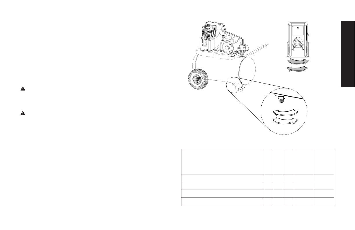
How to Use Your Unit (Fig 3)
How to Stop:
Set the Auto/Off switch to “Off”.
Before Starting
WARNING: Do not operate this unit until you read this instruction
manual for safety, operation and maintenance instructions.
Break-in Procedure
NOTICE: Risk of property damage. Serious damage may result if
the following break-in instructions are not closely followed.
This procedure is required before the air compressor is put into
service and when the check valve or a complete compressor pump
has been replaced.
1. Make sure the Auto/Off switch is in the “Off” position.
2. Check oil level in pump. See Oil paragraph in the Maintenance
section for instructions.
3. Plug the power cord into the correct branch circuit receptacle.
(Refer to Voltage and Circuit Protection paragraph in the
English
13
Page 14

installation section of this manual.)
4. Open the drain valve (counterclockwise) fully to permit air to
escape and prevent air pressure build up in the air tank during
the break-in period.
5. Move the Auto/Off switch to “Auto” position. The compressor
will start.
6. Run the compressor for 30 minutes. Make sure the drain valve
English
and all air lines are open so there is only a minimal air pressure
build-up in tank.
NOTE: After about 30 minutes, If the unit does not operate
properly, SHUT DOWN IMMEDIATELY, and contact
Product Service.
7. Check all air line fittings and connections/piping for air leaks
by applying a soap solution. Correct if necessary. NOTE: Minor
leaks can cause the air compressor to overwork, resulting in
premature breakdown or inadequate performance.
8. Check for excessive vibration. Readjust or shim air compressor feet, if necessary.
9. After 30 minutes, turn the Auto/Off switch to the “Off” position.
10. Close the drain valve.
11. Turn the Auto/Off switch to the “Auto” position. The air receiver
will fill to “cut-out” pressure and the motor will stop.
The compressor is now ready for use.
Before Each Start-Up
1. Place Auto/Off switch to “Off”.
2. Close the drain valve.
3. Visually inspect air lines and fittings for leaks.
4. Check safety valve. See To Check Safety Valve under
Maintenance.
5. Pull the regulator knob out and turn counterclockwise to set
the outlet pressure to zero.
6. Attach hose and accessories.
WARNING: Risk of unsafe operation. Firmly grasp air hose in
hand when installing or disconnecting to prevent hose whip.
WARNING: Risk of unsafe operation. Do not use damaged or
worn accessories.
NOTE: The hose or accessory will require a quick connect plug if
the air outlet is equipped with a quick connect socket.
WARNING: Risk of bursting. Too much air pressure causes a
hazardous risk of bursting. Check the manufacturer’s maximum
pressure rating for air tools and accessories. The regulator outlet
pressure must never exceed the maximum pressure rating.
CAUTION: Risk of unsafe operation. Compressed air from the
unit may contain wa ter condensation and oil mist. Do not spray un filtered air at an item that could be damaged by moisture. Some air
tools and accessories may require filtered air. Read the in struc tions
for the air tools and accessories.
How to Start
1. Turn the Auto/Off switch to “Auto” and allow tank pressure to
build. Motor will stop when tank pressure reaches “cut-out”
pressure.
2. Pull the regulator knob out and turn clockwise to increase pressure. When the desired pressure is reached push knob in to
lock in place.
IMPORTANT: When using regulator and other accessories refer to
the manufacturers instructions.
WARNING: Risk of bursting. If any unusual noise or vibration is
14
Page 15
noticed, stop the compressor immediately and have it checked by a
trained service technician.
The compressor is ready for use.
Shut-down (Fig. 1)
1. Move Auto/Off switch to the OFF position. NOTE: If finished
using compressor, follow Steps 2 - 6.
2. Pull the regulator knob out and turn counterclockwise until fully
closed. Ensure regulated pressure gauge reads 0 psi. Push
knob in to lock in place.
3. Remove hose and accessory.
WARNING: Risk of unsafe operation. Firmly grasp air hose in hand
when installing or disconnecting to prevent hose whip.
4. Drain the air tank,
Ensure air tank pressure gauge reads 0 psi.
WARNING: Risk of bursting. Drain air tank daily. Water will
condense in air tank. If not drained, water will corrode and weaken
the air tank causing a risk of air tank rupture.
5. Allow the compressor to cool down.
6. Wipe air compressor clean and store in a safe, non-freezing
area.
see Draining Air Tank under Maintenance
FIG. 3
English
OFF
AUTO
.
OPEN
CLOSE
MAINTENANCE
Maintenance Chart
Procedure
Check safety valve
Inspect air filter
Drain air tank
Check pump oil level
15
Daily
X
X
X
Weekly
+
X
1 year
Monthly
or 100
Hours
See tank
warning
label
Page 16
Change pump oil
Oil leak inspection
Inspect drive belt
Check drive belt tension
Check pulley/flywheel alignment
Check for unusual noise/vibration
Check for air leaks
English
Clean compressor exterior
Remove tank from service
* To check for air leaks apply a solution of soapy water around joints.
While compressor is pumping to pressure and after pressure cuts out,
look for air bubbles to form.
** The pump oil must be changed after the first 20 hours or operation.
Thereafter, when using
oil, change oil every 100 hours of operation or once a year, whichever
comes first.
+ Perform more frequent in dusty or humid conditions.
++
For more information, call 1-888-895-4549 .
synth
etic blend non-detergent air compressor
X
X
X
X
X*
X
+
X
**
X
WARNING: Risk of unsafe operation. Unit cycles automati-
cally when power is on. When performing maintenance, you may
be exposed to voltage sources, compressed air, or moving parts.
Personal injuries can occur. Before performing any maintenance or
repair, disconnect power source from the compressor and bleed off
all air pressure.
To ensure efficient operation and longer life of the air compressor
outfit, a routine maintenance schedule should be prepared and followed. The following routine maintenance schedule is geared to an
outfit in a normal working environment operating on a daily basis.
If necessary, the schedule should be modified to suit the conditions under which your compressor is used. The modifications will
depend upon the hours of operation and the working environment.
Compressor outfits in an extremely dirty and/or hostile environment
will require a greater frequency of all maintenance checks.
NOTE: See Operation section for the location of controls.
Checking Safety Valve (Fig. 1)
WARNING: Hot surfaces. Risk of burn. Tubes, pump head, and
surrounding parts are very hot, do not touch (see the Hot Surfaces
identified in Fig. 2). Allow compressor to cool prior to servicing.
++
X
WARNING: Risk of bursting. If the safety valve does not work
properly, over-pressurization may occur, causing air tank rupture or
an explosion.
WARNING: Risk from flying objects. Always wear certified safety
equipment: ANSI Z87.1 eye protection (CAN/CSA Z94.3) with side
shields.
Before starting compressor, pull the ring on the safety valve to
make sure that the safety valve operates freely. If the valve is stuck
or does not operate smoothly, it must be replaced with the same
type of valve.
Checking Air Filter (Fig. 1)
WARNING: Hot surfaces. Risk of burn. Tubes, pump head, and
surrounding parts are very hot, do not touch (see the Hot Surfaces
identified in Fig. 2). Allow compressor to cool prior to servicing.
A dirty air filter will not allow the compressor to operate at full
capacity. Keep the air filter clean at all times.
1. Ensure Auto/Off switch (B) is in the OFF Position.
2. Allow unit to cool.
3. Remove the 3 phillips screws and washers from the pump
head.
4. Remove the small plate, being careful not to drop anything
on the exposed valves.
16
Page 17

5. Carefully lift out the air filter and screens. NOTE: The screen
edges are sharp.
6. Place cleaned or new air filter between the screens and
insert back into grooves. Refer to the Replacement Parts
under Service.
7. Place the plate back onto the pump head, insert the screws
and washers, tighten the screws.
CAUTION: Risk of unsafe operation. Do not operate without air
filter.
Draining Air Tank (Fig. 3)
WARNING: Risk of unsafe operation. Air tanks contain high
pressure air. Keep face and other body parts away from outlet of
drain. Use eye protection [ANSI Z87.1 (CAN/CSA Z94.3)] when
draining as debris can be kicked up into face.
WARNING: Risk from noise. Use ear protection (ANSI S12.6
(S3.19) as air flow noise is loud when draining.
NOTE: All compressed air systems generate condensation that accumulates in any drain point (e.g., tanks, filter, aftercoolers, dryers). This
condensate contains lubricating oil and/or substances which may be
regulated and must be disposed of in accordance with local, state,
and federal laws and regulations.
1. Set the Auto/Off switch to “Off”.
2. Pull the regulator knob out and turn counterclockwise to set
the outlet pressure to zero.
3. Remove the air tool or accessory.
4. Pull ring on safety valve allowing air to bleed from the tank until
tank pressure is approximately 20 psi. Release safety valve
ring.
5. Drain water from air tank by opening drain valve (counterclockwise) on bottom of tank.
WARNING: Risk of bursting. Water will condense in the air tank.
If not drained, water will corrode and weaken the air tank causing a
risk of air tank rupture.
NOTICE: Risk of property damage. Drain water from air tank may
contain oil and rust which can cause stains.
6. After the water has been drained, close the drain valve (clockwise). The air compressor can now be stored.
NOTE: If drain valve is plugged, release all air pressure. The valve
can then be removed, cleaned, then reinstalled.
Compressor Pump Oil (Fig. 4)
NOTICE: Risk of property damage. Use air compressor oil only.
Multi-weight automotive engine oils like 10W30 should not be used
in air compressors. They leave carbon deposits on critical components, thus reducing performance and compressor life.
NOTE: Use synthetic blend, nondetergent
air compressor oil.
NOTE: Crankcase oil capacity is approximately 16 fluid ounces
(473,2 ml).
Checking
1. The oil level should be to the middle of the sight glass (T).
2. If needed remove oil fill plug (R) and slowly add oil until it
reaches the middle of the sight glass.
Changing
WARNING: Drain tank to release air pressure before removing the
oil fill cap or oil drain plug.
1. Remove the oil fill plug (U).
2. Remove the oil drain plug (S) and drain oil into a suitable con-
17
English
Page 18
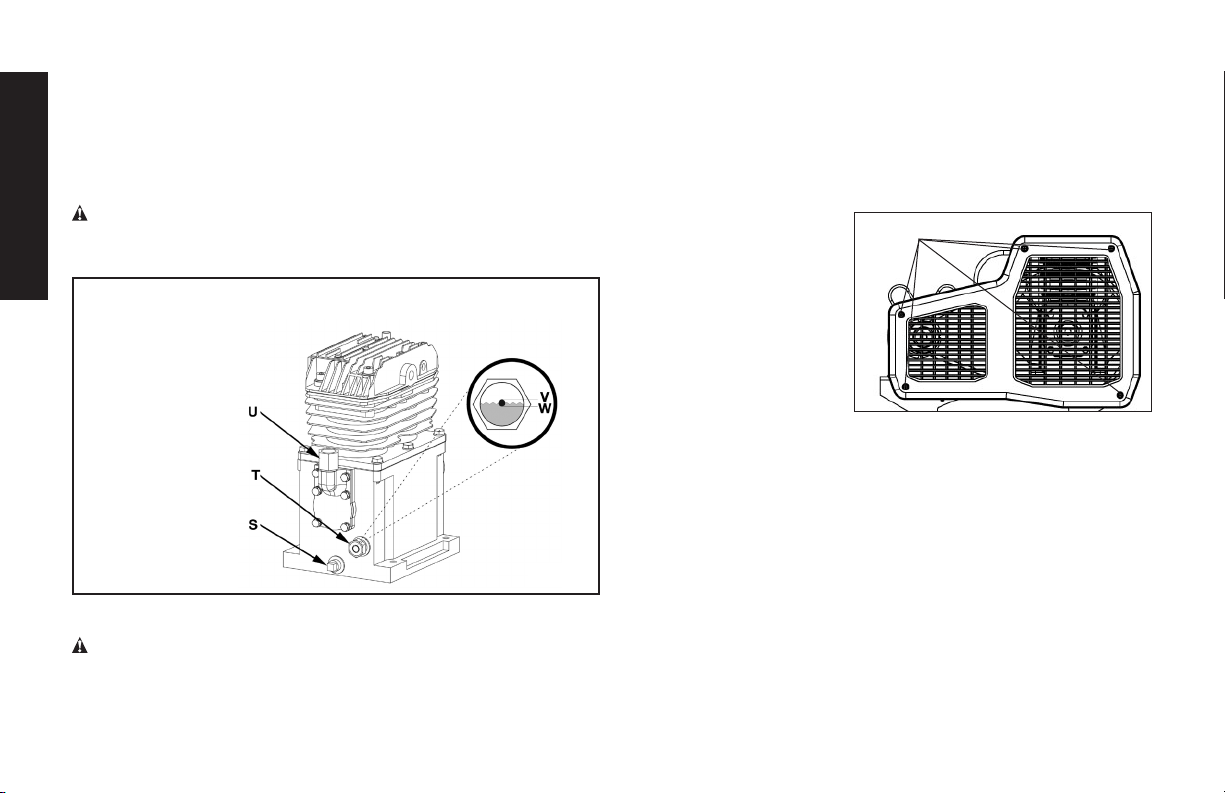
tainer.
3. Replace the oil drain plug (S) and tighten securely
4. Slowly add compressor oil until it reaches the middle of the
sight glass (T). NOTE: When filling the crankcase, the oil
flows very slowly into the pump. If the oil is added too quickly,
it will overflow and appear to be full.
CAUTION: Overfilling with oil will cause premature compressor
English
failure. Do not overfill.
5. Replace oil fill plug (U) and tighten securely.
V = Full
W = Add
S = Oil drain plug
T = Oil level sight glass
U = Oil fill plug
Belt Replacement
WARNING: This unit starts automatically. ALWAYS shut off
and unplug the compressor, and bleed all pressure from the
system before servicing the compressor, and when the
Fig. 4
compressor is not in use. Do not use the unit with the shrouds
or belt guard removed. Serious injury could occur from contact
with moving parts. Hot surfaces. Risk of burn. Pump head, and
surrounding parts are very hot, do not touch (see the Hot
Surfaces identified in Fig. 2). Allow compressor to cool prior to
servicing.
1. Set the Auto/Off lever to
“Off”, unplug the unit,
X
and relieve all air pressure from the air tank.
2. Remove the belt guard
by removing the 5 screws
(X) using a Phillips head
screwdriver.
3. Mark pump position on
saddle.
4. Loosen the motor mounting screws and slide the motor toward
the air compressor.
5. Remove the belt and replace with a new one.
6. See the Adjusting Belt Tension before tightening motor
mounting screws.
Adjusting Belt Tension
1. Slide motor into original position, line the motor up with the
mark made earlier on saddle.
2. Tighten two outside motor mounting screws enough to hold
the motor in place for checking pulley and flywheel alignment.
3. The belt should deflect 1/2” (13 mm)at midway between the
pulley and the flywheel when a 5 pound (2.26 kg.) weight is
applied at the midway point.
3. When proper belt tension is achieved, tighten all
18
Page 19
four motor mounting screws. Torque to 20-25 ft-lbs
(27.1–33.9 Nm).
NOTE: Once the engine
pulley has been moved
from its factory set location, the grooves of the flywheel and pulley must be
aligned to within 1/16”
(1.6mm) to prevent excessive belt wear. Verify the
alignment by performing
the following Motor Pulley/
Flywheel - Alignment.
Downward Force
Deflection
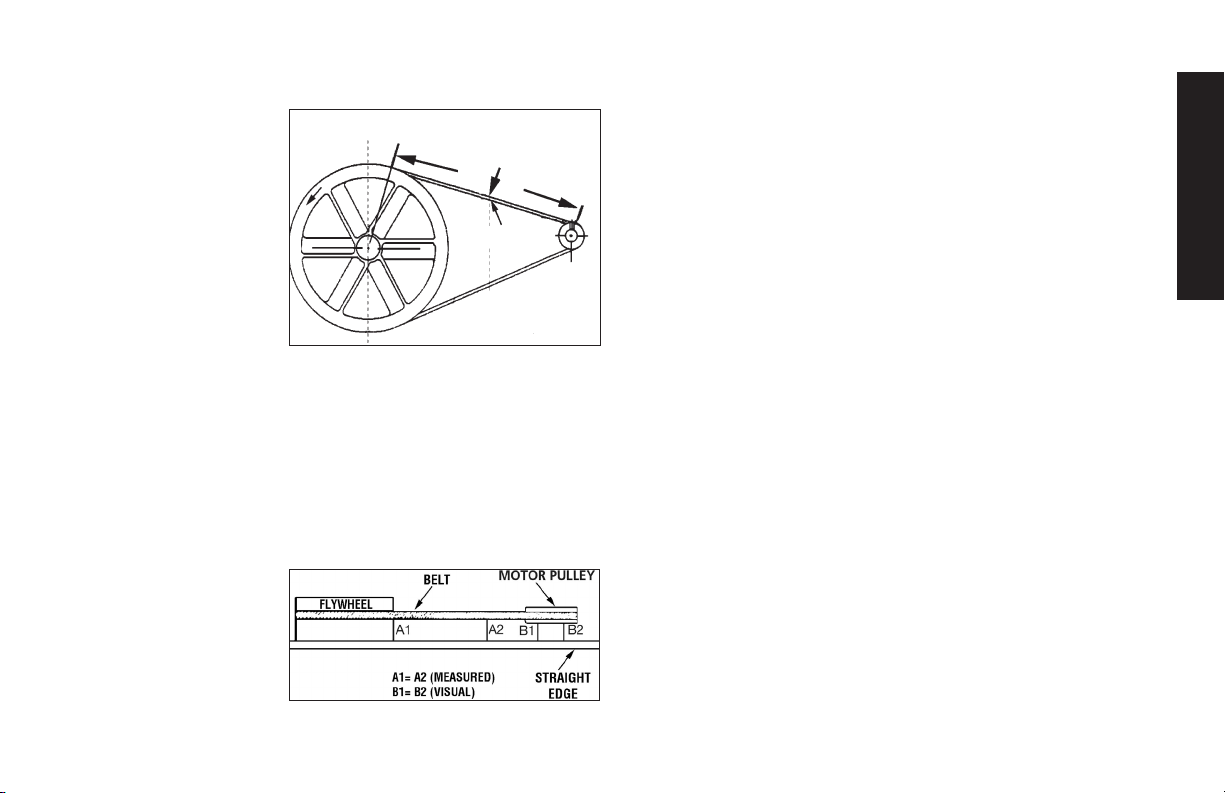
Motor Pulley/Flywheel Alignment
NOTE: Once the motor pulley has been moved from its factory set
location, the grooves of the flywheel and pulley must be aligned to
within 1/16” (1.6 mm) to prevent excessive belt wear.
The air compressor flywheel and motor pulley must be in-line (in the
same plane) within 1/16” (1.6 mm) to assure belt retention within
flywheel belt grooves. To check alignment, perform the following
steps:
1. Set the Auto/Off lever to “Off”, unplug the unit, and relieve all
air pressure from the air tank.
2. Remove belt guard.
3. Place a straightedge
against the outside of
the flywheel and the
motor drive pulley.
4. Measure the distance
between the edge of
the belt and the straightedge at points A1 and A2 in figure.
The difference between measurements should be no more than
1/16” (1.6 mm).
5. If the difference is greater than 1/16” (1.6 mm) loosen the set
screw holding the motor drive pulley to the shaft and adjust
the pulley’s position on the shaft until the A1 and A2 measurements are within 1/16” (1.6 mm) of each other.
6. Tighten the motor drive pulley set screw.
7. Visually inspect the motor drive pulley to verify that it is perpendicular to the drive motor shaft. Points B1 and B2 of Figure
should appear to be equal. If they are not, loosen the setscrew
of the motor drive pulley and equalize B1 and B2, using care
not to disturb the belt alignment performed in step 2.
8. Retighten the motor drive pulley setscrew. Torque to 145–165 in lbs
(16.4–20.3Nm).
9. Reinstall belt guard.
Air Compressor Pump Intake and Exhaust
Valves
Once a year have a Trained Service Technician check the air compressor pump intake and exhaust valves.
Inspect Air Lines and Fittings for Leaks
1. Set the Auto/Off lever to “Off”, unplug the unit, and relieve all
air pressure from the air tank.
2. Apply a soap solution to all air line fittings and connections/
piping.
3. Correct any leaks found.
IMPORTANT: Even minor leaks can cause the air compressor
to overwork, resulting in premature breakdown or inadequate
English
19
Page 20
performance.
Air compressor Head Bolts - Torquing
The air compressor pump head bolts should be kept properly
torqued. Check the torques of the head bolts after the first five
hours of operation. Torque to 14-16ft.-lbs. (18.9–21.7 Nm).
English
Service and Adjustments
ALL MAINTENANCE AND REPAIR OPERATIONS NOT LISTED
MUST BE PERFORMED BY TRAINED SERVICE TECHNICIAN.
Risk of unsafe operation. Unit cycles automatically when power is on. When servicing, you may be exposed
to voltage sources, compressed air, or moving parts. Before
servicing unit unplug or disconnect electrical supply to the air
compressor, bleed tank of pressure, and allow the air compressor to cool.
To Replace or Clean Check Valve
1. Release all air pressure from air tank. See Draining Air Tank in
the Maintenance section.
2. Set the Auto/Off lever to “Off”, unplug the unit, and relieve all
air pressure from the air tank.
3. Using an adjustable
wrench loosen outlet
tube nut at air tank
and pump. Carefully
move outlet tube
away from check
valve.
4. Using an adjustable
wrench loosen pres-
In open
position
nothing is
visible.
Screwdriver
In closed position
disc is visible.
sure relief tube nut at air tank. Carefully move pressure relief
tube away from check valve.
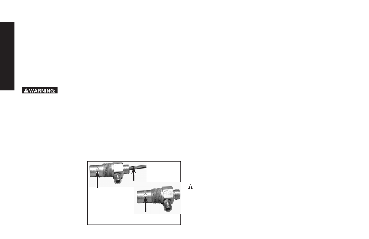
5. Unscrew the check valve (turn counterclockwise) using a 7/8”
open end wrench. NOTE the orientation for reassembly.
6. Using a screwdriver, carefully push the valve disc up and
down. NOTE: The valve disc should move freely up and down
on a spring which holds the valve disc in the closed position, if
not the check valve needs to be cleaned or replaced.
7. Clean or replace the check valve. A solvent, such as paint or
varnish remover can be used to clean the check valve.
8. Apply sealant to the check valve threads. Reinstall the check
valve (turn clockwise).
9. Replace the pressure release tube. Tighten nuts.
10. Replace the outlet tube and tighten nuts.
11. Perform the Break-in Procedure. See Break-in Procedure in
the Operation section.
Additional Service
Disassembly or service of the air compressor beyond what is covered in this manual is not recommended. If additional service is
required, contact your nearest Authorized Warranty Service Center.
Accessories
Recommended accessories for use with your tool are available for
purchase from your local dealer or authorized service center. If you
need assistance in locating any accessory for your tool, please call
1-888-895-4549 or visit our website www.dewalt.com.
WARNING: The use of any other accessory not recommended
for use with this tool could be hazardous. Use only accessories
rated equal to or higher than the rating of the air compressor.
20
Page 21

Service Information
Please have the following information available for all service calls:
Model Number ____________ Serial Number ___________
Date and Place of Purchase ____________________________
Repairs
To assure product SAFETY and RELIABILITY, repairs, maintenance
and adjustment should be performed by a DeWALT factory service
center, a DeWALT authorized service center or other qualified
service personnel. Always use identical replacement parts.
Limited Warranty
DEWALT Industrial Tools are warranted from date of purchase.
2 Year – Limited warranty on oil-lubricated air compressor
pumps.
1 Year – Limited warranty on all other air compressor
components. This warranty is not transferable to
subsequent owners.
DEWALT will repair or replace, without charge, at DEWALT’s
option, any defects due to faulty materials or workmanship.
For further detail of warranty coverage and warranty repair
information, call 1-(888)-895-4549 or visit dewalt.com. This
warranty does not apply to accessories or damage caused where
repairs have been made or attempted by others. This warranty
also does not apply to merchandise sold by DEWALT which has
been manufactured by and identied as the product of another
company, such as gasoline engines. Such manufacturer’s
warranty, if any, will apply. ANY INCIDENTAL, INDIRECT OR
CONSEQUENTIAL LOSS, DAMAGE OR EXPENSE THAT MAY
RESULT FROM ANY DEFECT, FAILURE OR MALFUNCTION OF
THE PRODUCT IS NOT COVERED BY THIS WARRANTY. Some
states do not allow the exclusion of limitation of incidental or
consequential damages, so the above limitation or exclusion may
not apply to you. IMPLIED WARRANTIES, INCLUDING THOSE
OF MERCHANTABILITY OR FITNESS FOR A PARTICULAR
PURPOSE, ARE LIMITED TO ONE YEAR FROM THE DATE OF
ORIGINAL PURCHASE. Some states do not allow limitations on
how long an implied warranty lasts, so the above limitations may
not apply to you.
What the Company Will Do: (the company) will cover parts
and labor to remedy substantial defects due to materials
and workmanship during the rst year of ownership, with the
exceptions noted below. Parts used in repair of whole goods or
accessories are warranted for the balance of the original warranty
period.
What is not covered Under This Warranty? Failures by the
original retail purchaser to install, maintain, and operate said
equipment in accordance with standard industry practices.
Modications to the product, or tampering with components,
or failure to comply with the specic recommendations of the
Company set forth in the owner’s manual, will render this warranty
null and void. The Company shall not be liable for any repairs,
replacements, or adjustments to the equipment, or any costs for
labor performed by the purchaser without the Company’s prior
written approval. The effects of corrosion, erosion, surrounding
environmental conditions, cosmetic defects, and routine
maintenance items, are specically excluded from this warranty.
Routine maintenance items such as: oil, lubricants, and air lters,
as well as changing oil, air lters, belt tensioning, etc… fall under
the owner’s responsibility. Additional exclusions include: freight
damage, failures resulting from neglect, accident, or abuse,
induction motors when operated from a generator, oil leaks, air
leaks, oil consumption, leaky ttings, hoses, petcocks, bleeder
English
21
Page 22

tubes, and transfer tubes.
• The following components are considered normal wear
items and are not covered after the rst year of
ownership: Belts, sheaves, ywheels, check valves,
pressure switches, air unloaders, throttle controls,
electric motors, brushes, regulators, o-rings, pressure
gauges, tubing, piping, ttings, fasteners, wheels, quick
English
couplers, gaskets, seals, air lter housings, piston rings,
connecting rods, and piston seals.
• Labor, service calls, and travel charges, are not covered
after the rst year of ownership on stationary
compressors (compressors without handles, or wheels).
Repairs requiring overtime, weekend rates, or any other
charges beyond the standard shop labor rate are not
covered.
• Time required for orientation training for the service
center to gain access to the product, or additional time
due to inadequate egress.
• Damage caused by incorrect voltage, improperly wired,
or failure to have a certied licensed electrician install
the compressor, will render this warranty null and void.
• Damage caused from inadequate lter maintenance.
• Pump wear or valve damage caused by using oil not
specied.
• Pump wear or damage caused by any oil contamination.
• Pump wear or valve damage caused by failure to follow
proper maintenance guidelines.
• Operation below proper oil level or operation without oil.
• Gas Engines, if product is equipped with a gas engine,
see engine manual for specic engine manufacturer’s
warranty coverage.
Parts purchased separately: The warranty for parts purchased
separately such as: pumps, motors, etc., are as follows:
From Date of Purchase
• All single & two stage pumps 1 year
• Electric motors 90 days
• Universal motor/pump 30 days
• All other parts 30 days
• No return authorization will be issued for electrical
components once items are installed.
How do You Get Service? In order to be eligible for service
under this warranty you must be the original retail purchaser,
and provide proof of purchase from one of the Company’s
dealers, distributors, or retail outlet stores. Portable compressors
or components must be delivered, or shipped, to the nearest
Authorized Service Center. All associated freight costs and travel
charges must be borne by the consumer. Please call our toll free
number 1-888-895-4549 for assistance.
THIS WARRANTY GIVES YOU SPECIFIC LEGAL RIGHTS, AND
YOU MAY ALSO HAVE OTHER RIGHTS WHICH VARY FROM
STATE TO STATE.
THE COMPANY MAKES NO OTHER WARRANTY OR
REPRESENTATION OF ANY KIND WHATSOEVER,
EXPRESSED OR IMPLIED, EXCEPT THAT OF TITLE. ALL
IMPLIED WARRANTIES, INCLUDING ANY WARRANTY
OF MERCHANTABILITY AND FITNESS FOR PARTICULAR
PURPOSE ARE HEREBY DISCLAIMED. LIABILITY FOR
22
Page 23
CONSEQUENTIAL AND INCIDENTAL DAMAGES UNDER ANY
AND ALL WARRANTIES, OTHER CONTRACTS, NEGLEGENCE,
OR OTHER TORTS IS EXCLUDED TO THE EXTENT EXCLUSION
IS PERMITTED BY LAW.
FREE WARNING LABEL REPLACEMENT: If your warning labels
become illegible or are missing, call 1-888-895-4549 for a free
replacement.
GLOSSARY
CFM: Cubic feet per minute.
SCFM: Standard cubic feet per minute; a unit of measure of air
delivery.
PSI: Pounds per square inch; a unit of measure of pressure.
Cut-in pressure: Factory set low pressure point that starts the
compressor to repressurize the tank to a higher pressure.
Cut-out pressure: Factory set high pressure point that stops
the compressor from increasing the pressure in the tank above a
certain level.
Well-ventilated: A means of providing fresh air in exchange for
dangerous exhaust or vapors.
Dedicated circuit: An electrical circuit reserved for the exclusive
use of the air compressor.
ASME: American Society of Mechanical Engineers. Indicates that
the components are manufactured, tested and inspected to the
specifications set by ASME.
CSA: Canadian Standards Association
Indicates that the products that have this marking have
been manufactured, tested and inspected to standards
that are set by CSA.
Canadian Standards Association (USA): Indicates that the
products that have this marking have been
manufactured, tested and inspected to standards that
are set by CSA. These products also conform to U.L.
standard 1450.
California Code: Unit may comply with California Code 462 (l) (2)/
(M) (2). Specification/model label is on the side of the air tank on
units that comply with California Code.
English
23
Page 24

Troubleshooting Guide
This section provides a list of the more frequently encountered malfunctions, their causes and corrective actions. The operator or
maintenance personnel can perform some corrective actions, and others may require the assistance of a qualified DeWALT technician or
your dealer.
Problem Code
English
Air leaks .................................................................................................................................... 1
Air leaks in air tank or at air tank welds .................................................................................... 2
Air leaks between head and valve plate ....................................................................................3
Air leaks from safety valve .........................................................................................................4
Compressor is not supplying enough air to operate accessories ............................................ 1, 5, 6, 7, 9, 10
Restricted air intake. .................................................................................................................. 9
Oil in discharge air ..................................................................................................................... 9, 19, 31
Knocking Noise ......................................................................................................................... 4, 10, 11, 12, 13, 14
Excessive belt wear ................................................................................................................... 10, 11, 14, 15
Squealing sound ........................................................................................................................ 10
Moisture in pump crankcase ..................................................................................................... 1, 3, 8, 17, 18, 19, 20, 21, 22
Excessive current draw ............................................................................................................. 14, 26, 27
Compressor won’t start in cold temperatures ..........................................................................17, 34, 35
Pressure reading on the regulated pressure gauge drops when and accessory is used ......... 23
Regulator knob has continuous air leak .................................................................................... 24
Regulator will not shut off air outlet .......................................................................................... 24
Air tank pressure will not build .................................................................................................. 25
Compressor stalls ...................................................................................................................... 28, 29, 30
Overheating ...............................................................................................................................27, 32, 33
24
Page 25

Troubleshooting Codes
CODE POSSIBLE CAUSE POSSIBLE SOLUTION
1 Fittings are not tight Tighten fittings where air can be heard escaping. Check fittings
with soapy water solution. DO NOT OVERTIGHTEN.
2 Defective air tank Air tank must be replaced. Do not repair the leak.
WARNING: Risk of bursting. Do not drill into, weld or otherwise
modify air tank or it will weaken. The air tank can rupture or
explode.
3 Leaking seals Contact a DeWALT factory service center or a DeWALT authorized
service center.
4 Defective safety valve Operate safety valve manually by pulling on ring. If valve still
leaks, it must be replaced.
5 Prolonged excessive use of air Decrease amount of air usage.
6 Compressor is not large enough for accessory Check the accessory air requirement. If it is higher than the SCFM
or pressure supplied by your air compressor, a larger compressor
is needed to operate accessory.
7 Hole in air hose Check and replace air hose, if required.
8 Unit operating in damp or humid conditions Move unit to a dry well ventilated area.
9 Restricted air intake filter Clean or replace air intake filter.
10 Loose belt Check belt tension, see Adjusting Belt Tension under
Maintenance.
11
12
13
Loose pulley Tighten pulley set screw, torque to 85-90 in.-lbs. (9.6–10.2Nm).
Loose flywheel Tighten flywheel screw, torque to 14–18 ft.-lbs.
(20.0–24.4 Nm).
Carbon build-up in pump Contact a DeWALT factory service center or a DeWALT authorized
service center.
English
25
Page 26

CODE POSSIBLE CAUSE POSSIBLE SOLUTION
14
Belt to tight Check belt tension, see Adjusting Belt Tension under
Maintenance.
15
16
English
17
Pulley misalignment See Motor Pulley/Flywheel Alignment under Maintenance.
Pump oil is low Add synthetic blend, non-detergent air compressor oil to pump.
See Compressor Pump Oil under Maintenance.
Detergent type oil being used in pump Drain oil and refill pump with synthetic blend non-detergent air
compressor oil.
18
Extremely light duty cycles Run unit for longer duty cycles. It is recommended to run at high
throttle 50-75% of the run time and idle for 25% of the run time.
19
Piston rings damaged or worn Contact a DeWALT factory service center or a DeWALT authorized
service center.
20
Cylinder or piston damaged or worn Contact a DeWALT factory service center or a DeWALT authorized
service center.
21
Compressor cylinder finish worn Contact a DeWALT factory service center or a DeWALT authorized
service center.
22
Water in pump oil Drain oil and refill pump with synthetic blend non-detergent air
compressor oil.
23
Regulator is not adjusted correctly for accessory
being used.
It is normal for some pressure drop to occur when and acces-
sory is used, adjust the regulator as instructed in Regulator under
Features if pressure drop is excessive.
NOTE: Adjust the regulated pressure under flow conditions while
the accessory is being used.
24
25
Damaged regulator Replace
Regulator open Roate the regulator knob counter-clockwise to its built-in stop and
push knob in to lock in place.
26
Page 27

CODE POSSIBLE CAUSE POSSIBLE SOLUTION
26
Low voltage/motor overload Check that power supply is adequate and that compressor is
on a dedicated circuit. If using extension cord, try using without.
If compressor is connected to a circut protected by a fuse, use
dual element time delay fuses (Buss Fusetron type “T” only).
27
Restricted air passages Inspect and replace transfer tubes or check valve, as
required.
28
29
30
Low voltage motor Furnish adequate powder.
Bad check valve Replace check valve.
Seized pump Contact a DeWALT factory service center or a DeWALT authorized
service center.
31
Oil level too high Reduce to proper level. See Compressor Pump Oil under
Maintenance.
32
Poor ventilation Relocate compressor to an area with cool, dry, well circulated
air, at least 12 in. from nearest wall.
33
34
35
Dirty cooling surfaces Clean all cooling surfaces thoroughly.
Too much back pressure in tank. Open drain valve when starting motor.
Compressor too cold Move compressor to a warmer location.
English
27
Page 28

Compresseur d’air
A. Filtre d’admission d’air de la pompe
B. Interrupteur Auto [AUTO(-)] / Off (ARRÉT(O)]
C. Manomètre du réservoir d’air
D. Manomètre régulé
E. Régulateur de pression
F. Sortie d’air
G. Soupape de sûreté
H. Soupape de purge du réservoir d’air
I. Jauge graduée de l’huile de la pompe/Bouchon de
remplissage d’huile
J. Bouchon de vidange d’huile de la pompe
K. Clapet
L. Branchements rapides
Caractéristiques techniques de la pompe
Deux Cylindres
Mono-étagée
Français
Lubrifiée à l’huile
Carter en fonte et piston et culasse en aluminium
Poids : 18,6 kg (41 lb)
Capacité en huile : 473 ml (16 onces)
Fiche technique
MODÈLE
POIDS
HAUTEUR
LARGEUR
CAPACITÉ DU RÉSERVOIR D’AIR
ENV. PRESSION DE ÉCLENCHEMENT
DXCMPA1982054
75 kg (165 livres)
33.625”
34.188”
75,5 liters (20 gallons)
175 psi
A
I
J
K
H
C
G
B
D
F
L
E
FIG. 1
28
Page 29
Surfaces chaudes
TÊTE DE POMPE ET
CYLINDRE
CARTER DE
LA POMPE
TUBE DE SORTIE
FIG. 2
Dénitions : lignes directrices en matière
de sécurité
Les définitions ci-dessous décrivent le niveau de gravité pour
chaque symbole. Veuillez lire le mode d’emploi et porter une
attention particulière à ces symboles.
DANGER : Indique une situation dangereuse imminente qui, si
elle n’est pas évitée, causera la mort ou des blessures graves.
AVERTISSEMENT :
dangereuse qui, si elle n’est pas évitée, pourrait se solder par un
décès ou des blessures graves.
ATTENTION : Indique une situation potentiellement dangereuse
qui, si elle n’est pas évitée pourrait se solder par des blessures
mineures ou modérées.
AVIS : Indique une pratique ne posant aucun risque de
dommages corporels mais qui par contre, si rien n’est fait pour
l’éviter, pourrait poser des risques de dommages matériels.
POUR TOUTES QUESTIONS OU COMMENTAIRES RELATIFS(VES)
À L’OUTIL OU À PROPOS DE TOUT AUTRE OUTIL DEWALT,
COMPOSER SANS FRAIS LE : 1-888-895-4549
Indique une situation potentiellement
Directives de sécurité importantes
AVERTISSEMENT : Ne pas utiliser l’appareil avant d’avoir lu le
mode d’emploi, ainsi que l’intégralité des directives de sécurité, et
d’entretien.
AVERTISSEMENT: CALIFORNIE PROPOSITION 65
AVERTISSEMENT:
reconnus par l’État de Californie comme étant cancérigènes et pouvant entraîner des anomalies congénitales et d’autres dangers relatifs
à la reproduction.
Ce produit contient des produits chimiques,
Se laver les mains après toute manipulation.
Français
29
Page 30

AVERTISSEMENT :
reconnus par l’État de la Californie comme étant cancérigènes et
pouvant entraîner des anomalies congénitales ou d’autres problèmes liés aux fonctions reproductrices. Se laver les mains après
toute manipulation.
Ce produit contient des produits chimiques
CONSERVER CES DIRECTIVES
DANGER :
CE QUI PEUT SE PRODUIRE COMMENT L’ÉVITER
• Ilestnormalquedes
contacts électriques
dans le moteur et le
manocontacteur fassent
une étincelle.
Français
• Siuneétincelleélectrique
provenant du compresseur
entre en contact avec des
vapeurs inflammables,
elle peut s’enflammer et
causer un incendie ou une
explosion.
RISQUE D’EXPLOSION OU D’INCENDIE
• Faitestoujoursfonctionner
le compresseur dans une
zone bien aérée sans matière
combustible, essence ou
vapeur de solvant.
• Sivousaspergezdes
matériaux inflammables,
placez le compresseur à
au moins 6,1 m (20 pieds)
de la zone pulvérisée. Il est
possible que vous ayez
besoin d’une longueur de
tuyau additionnelle.
• Entreposezlesmatières
inflammables dans un
endroit sécuritaire, éloigné du
compresseur.
• Lefaitdelimiterles
ouvertures d’aération de
compresseur causera une
importante surchauffe et
pourrait causer un incendie.
• Lefonctionnementdece
produit sans surveillance
pourrait se solder par des
blessures personnelles
ou des dommages à la
propriété. Afin de réduire
le risque d’incendie, ne
pas laisser le compresseur
fonctionner sans
surveillance.
•Nejamaisplacerd’objets
contre la pompe du
compresseur ou sur celle-ci.
• Faitesfonctionnerle
compresseur dans un
endroit aéré à au moins
30,5 cm (12 po) du mur ou
de l’obstruction qui pourrait
limiter le débit d’air frais dans
les ouvertures d’aération.
• Faitesfonctionnerle
compresseur dans un endroit
propre, sec et bien aéré.
Ne pas utiliser l’appareil à
l’intérieur ou dans un endroit
exigu.
• Êtretoujoursprésentlorsque
le produit est en marche.
• Toujourséteindreet
débrancher l’appareil si non
utilisé.
30
Page 31

DANGER : RISQUE REPIRATOIRE (ASPHYXIE)
CE QUI PEUT SE PRODUIRE COMMENT L’ÉVITER
• Ilestdangereuxderespirer
l’air comprimé sortant du
compresseur.Lefluxd’air
peut contenir du monoxyde
de carbone, des vapeurs
toxiques ou des particules
solides provenant du
réservoird’air.Larespiration
de ces contaminants
peut causer de sérieuses
blessures, voire la mort.
Une exposition aux produits
•
chimiques présents dans
la poussière générée par
les activités de ponçage,
sciage, meulage, perçage et
autres, peut être nocive
•
Lesmatériauxvaporisés
comme la peinture, les
solvants de peinture, les
décapants, les insecticides,
les herbicides, pourraient
contenir des vapeurs
nocives et du poison.
• Nejamaisutiliserl’airobtenu
directement du compresseur
pour l’alimentation en air
destinée à la consommation
humaine.Lecompresseur
n’est pas muni de filtres et
d’équipement de sécurité
en ligne qui conviennent à la
consommation humaine.
•
Travailler dans un endroit
ayant une bonne aération
transversale.Lireetrespecter
les directives en matière
de sécurité imprimées sur
l’étiquette ou les fiches
signalétiques des matériaux
quisontpulvérisés.Toujours
utiliser un équipement de
sécurité homologué : une
protection respiratoire
conforme aux normes
NIOSH/OSHA, ou un masque
facialbienajusté,conçus
spécifiquement pour votre
utilisation particulière.
Réservoir d’air comprimé: Le 26 février 2002, la U.S. Consumer
DANGER : RISQUE D’ÉCLATEMENT
Product Safety Commission américaine a publié la règle nº 02-108
portant sur la sécurité en matière de réservoir d’air comprimé des
compresseurs:
Les réservoirs d’air comprimé des compresseurs n’ont pas une
durée de vie illimitée. La durée de vie des réservoirs dépend de
plusieurs facteurs, qui comprennent entre autres : les conditions
d’utilisation, les conditions ambiantes, une installation adéquate,
les modifications sur site, et le niveau de maintenance. L’effet exact
que peut avoir ces facteurs sur la durée de vie des réservoirs d’air
est difficilement prévisible.
Si les procédures adéquates de maintenance ne sont pas suivies,
la corrosion sur la paroi interne du réservoir d’air comprimé peut
faire que celui-ci éclate de façon inopinée laissant soudainement
l’air pressurisé s’échapper avec force, posant ainsi des risques de
dommages corporels à l’utilisateur.
Le réservoir d’air de votre compresseur doit être mis hors service à
la fin de l’année mentionnée sur l’étiquette d’avertissement apposée sur le réservoir.
Les conditions suivantes peuvent amener la dégradation du réservoir d’air, et faire que ce dernier explose violemment:
Français
31
Page 32

CE QUI PEUT SE PRODUIRE COMMENT L’ÉVITER
• L’eau condensée n’est pas
correctement vidangée du
réservoir d’air provoquant
ainsi la formation de rouille et
un amincissement du réservoir
d’air en acier.
• Modifications apportées au
réservoir d’air ou tentatives de
réparation.
Français
• Des modifications non
autorisées de la soupape
de décompression, ou de
tous autres composants
qui régissent la pression du
réservoir d’air.
• Vidanger le réservoir d’air
quotidiennement ou après
chaque utilisation. Si le réservoir
présente une fuite, le remplacer
immédiatement par un nouveau
réservoir d’air ou par un
nouveau compresseur.
• Ne jamais percer un trou
dans le réservoir d’air ou
ses accessoires, y faire de la
soudure ou y apporter quelque
modification que ce soit. Ne
jamais essayer de réparer un
réservoir d’air endommagé ou
avec des fuites. Le remplacer
par un nouveau réservoir d’air.
• Le réservoir d’air a été conçu
pour supporter des pressions
spécifiques de fonctionnement.
Ne faites jamais effectuer de
réglages ou de substitutions de
pièces en vue de modifier les
pressions de fonctionnement
réglées en usine.
Attachements et accessoires :
• Lorsqu’on excède la
pression nominale des
outils pneumatiques, des
pistolets pulvérisateurs, des
accessoires à commande
pneumatique, des pneus
et d’autres dispositifs
pneumatiques, on risque de
les faire exploser ou de les
projeter et ainsi entraîner des
blessures graves.
Pneus :
• Des pneus surgonflés
pourraient provoquer des
blessures graves et des
dommages à la propriété.
• Respecter les
recommandations du fabricant
de l’équipement et ne jamais
dépasser la pression nominale
maximale permise des
accessoires. Ne jamais utiliser
le compresseur pour gonfler de
petits objets à basse pression
comme des jouets d’enfant,
des ballons de football et de
basketball, etc.
• Utiliser un manomètre pour
vérifier la pression des pneus
avant chaque utilisation et
lors du gonflage; consulter le
flanc de pneu pour obtenir la
pression correcte.
REMARQUE: Les réservoirs
d’air comprimé, compresseurs
et autres équipements similaires
utilisés pour gonfler les pneus
peuvent remplir ces derniers
très rapidement. Régler le
régulateur de pression d’air à
une pression moindre que celle
indiquée sur le pneu. Ajouter de
l’air par petite quantité et utiliser
fréquemment le manomètre
pour empêcher un surgonflage.
32
Page 33

DANGER : RISQUE DE BLESSURES OU DE DOMMAGES À LA
PROPRIÉTÉ LORS DU TRANSPORT OU DU RANGEMENT
CE QUI PEUT SE PRODUIRE COMMENT L’ÉVITER
• L’huile peut fuire ou se
déverser. Cela pourrait se
solder par un incendie ou
un danger d’inhalation; des
blessures graves ou un
décès. Les fuites d’huile
endommageront le tapis,
la peinture ou toutes autres
surfaces de véhicules ou de
remorques.
• Toujours installer le
compresseur sur un revêtement
protecteur lors du transport
pour protéger le véhicule de
tous dommages associés aux
fuites. Retirer immédiatement le
compresseur du véhicule dès
l’arrivée à destination. Toujours
tenir le compresseur à niveau
et ne jamais le déposer sur son
côté.
Français
33
Page 34

AVERTISSEMENT : ATTENTION SURFACES CHAUDES
CE QUI PEUT SE PRODUIRE COMMENT L’ÉVITER
• Toucher à du métal
exposé comme la tête du
compresseur ou de sortie,
peut se solder en de sérieuses
brûlures.
• Ne jamais toucher à des
pièces métalliques exposées
sur le compresseur pendant
ou immédiatement après son
utilisation. Le compresseur
restera chaud pendant
plusieurs minutes après son
utilisation.
• Ne pas toucher ni effectuer
des réparations aux coiffes de
protection avant que l’appareil
n’ait refroidi.
Français
AVERTISSEMENT : RISQUE DE CHOC ÉLECTRIQUE
CE QUI PEUT SE PRODUIRE COMMENT L’ÉVITER
• Votrecompresseurd’airest
alimenté à l’électricité. Tout
comme n’importe quel autre
dispositif alimenté de façon
électrique, s’il n’est pas
utilisé correctement, il peut
causer un choc électrique.
• Nefaitesjamaisfonctionner
le compresseur à l’extérieur
lorsqu’il pleut ou dans des
conditions humides.
• Nefaitesjamaisfonctionner
le compresseur avec les
couvercles de protection
enlevés ou endommagés.
• Lestentativesderéparation
par un personnel non
qualifié peuvent résulter en
de graves blessures, voire
la mort par électrocution.
•
Mise à la terre
électrique :
le fait de ne
pas faire une mise à la terre
adéquate de ce produit
pourrait résulter en des
blessures graves voire la
mort par électrocution.
Consulter
les directives
relatives à la mise à la
terre
sous
Installation.
34
• Toutcâblageélectriqueou
toute réparation nécessaire
pour ce produit doit être
pris en charge par un centre
de réparation en usine
autorisé DeWALTouun
centre de réparation DeWALT
conformément aux codes
électriques nationaux et
locaux.
• Assurez-vousquele
circuit électrique auquel le
compresseur est branché
fournit une mise à la terre
électrique adéquate, une
tension appropriée et une
bonne protection des
fusibles.
Page 35

AVERTISSEMENT : RISQUE ASSOCIÉ À UTILISATION
DANGEREUSE
CE QUI PEUT SE PRODUIRE COMMENT L’ÉVITER
• Une utilisation dangereuse
de votre compresseur d’air
pourrait provoquer de graves
blessures, voire votre décès
ou celle d’autres personnes.
• Revoir et comprendre toutes les
directives et les avertissements
contenus dans le présent mode
d’emploi.
• Se familiariser avec le
fonctionnement et les
commandes du compresseur
d’air.
• Dégager la zone de travail de
toutes personnes, animaux et
obstacles.
• Tenir les enfants hors de portée
du compresseur d’air en tout
temps.
• Ne pas utiliser le produit en cas
de fatigue ou sous l’emprise
d’alcool ou de drogues. Rester
vigilant en tout temps.
• Ne jamais rendre inopérant les
fonctionnalités de sécurité du
produit.
• Installer un extincteur dans la
zone de travail.
• Ne pas utiliser l’appareil lorsqu’il
manque des pièces ou que
des pièces sont brisées ou non
autorisées.
• Ne jamais se tenir debout sur le
compresseur.
AVERTISSEMENT : RISQUE ASSOCIÉ AUX PIÈCES MOBILES
CE QUI PEUT SE PRODUIRE COMMENT L’ÉVITER
• Les pièces mobiles comme
une poulie, un volant ou une
courroie peuvent provoquer
de graves blessures si elles
entrent en contact avec vous
ou vos vêtements.
• Utiliser le compresseur avec
des pièces endommagées
ou manquantes ou le réparer
sans coiffes de protection
risque de vous exposer à
des pièces mobiles et peut
se solder par de graves
blessures.
35
• Ne jamais utiliser le
compresseur si les protecteurs
ou les couvercles sont
endommagés ou retirés.
• Garder les cheveux, les
vêtements et les gants à
l’écart des pièces mobiles.
Les vêtements amples, bijoux
ou cheveux longs peuvent
s’enchevêtrer dans les pièces
mobiles.
• S’éloigner des évents car ces
derniers pourraient camoufler
des pièces mobiles.
• Toutes les réparations requises
pour ce produit devraient être
effectuées par un centre de
réparation de l’usine DeWALT
ou un centre de réparation
agréé DeWA LT.
Français
Page 36

AVERTISSEMENT : RISQUE DE BLESSURE
EN SOULEVANT LE PRODUIT
CE QUI PEUT SE PRODUIRE COMMENT L’ÉVITER
• Soulever un objet trop lourd
peut se solder par de graves
blessures.
ATTENTION : RISQUES CAUSÉS PAR LE BRUIT
CE QUI PEUT SE PRODUIRE COMMENT L’ÉVITER
• Dans certaines conditions et
Français
selon la durée d’utilisation, le
bruit provoqué par ce produit
peut contribuer à une perte
auditive.
• Le compresseur est trop lourd
pour être soulevé par une
seule personne. Demander de
l’aide avant de le soulever.
• Toujours utiliser un équipement
de sécurité homologué : protection auditive conforme à la
norme ANSI S12.6 (S3.19).
CONSERVER CES CONSIGNES
POUR UTILISATION ULTÉRIEURE
FAMILIARISEZ-VOUS AVEC VOTRE
COMPRESSEUR D’AIR
LISEZ CE GUIDE DE L’UTILISATEUR ET TOUTES LES MESURES
DE SÉCURITÉ AVANT D’UTILISER CET APPAREIL. Comparez
les illustrations à votre appareil pour vous familiariser avec
l’emplacement des commandes et boutons de réglage. Conservez
ce guide pour références ultérieures.
CARACTÉRISTIQUES (Fig. 1)
INTERRUPTEUR AUTO (-)/ARRÊT (OFF) (O)
Mettre cet interrupteur (B) sur la position AUTO
(-) pour avoir une alimentation automatique au
manocontacteuretsur lapositionARRÊT(OFF)
(O) pour la mise hors tension à la fin de chaque
utilisation. REMARQUE : Avant de retirer ou de
replacer le capot du manocontacteur, s’assurer
de TOUJOURS mettre l’interrupteur (B) à laposition d’ARRÊT
(OFF) (O).
MANOCONTACTEUR
Le manocontacteur (B) démarre automatiquement le moteur
lorsque la pression du réservoir d’air chute sous la pression
d’enclenchement réglée en usine. Il arrête le moteur lorsque la
pression du réservoir d’air atteint la pression de déclenchement
réglée en usine.
SOUPAPE DE SÛRETÉ
Lasoupape(G)estconçuepourprévenirdes
défaillances système en décompressant
celui-ci lorsque le compresseur d’air atteint
un niveau préétabli. La soupape est réglée
par le fabricant et ne doit pas être retirée ou
modifiée de quelque manière que ce soit.
CLAPET
Lorsque le compresseur d’air fonctionne, le
clapet (K) est ouvert, ce qui permet à l’air
comprimé d’entrer dans le réservoir d’air.
Lorsque le compresseur d’air atteint la
pression de déclenchement, le clapet se
ferme, ce qui permet à la pression d’air de
B
G
K
36
Page 37

rester dans le réservoir d’air.
FILTRE D’ADMISSION D’AIR
Lefiltre(A)sertàpurifierl’airquientedansla
A
pompe. Pour que la pompe reçoive un flux d’air
constantpropre,froidetsec,lefiltredoittoujours
être propre et l’entrée d’air doit être exempte
d’obstructions.
ROBINET DE PURGE
Lerobinetdepurge(H)setrouveàla
base du réservoir d’air et est utilisé
pour vidanger la condensation à la fin
de chaque utilisation.
chapitre Vidange du réservoir sous
Consulter le
H
Entretien.
MANOMÈTRE RÉGULÉ
Lemanomètredeprise(D)indique
la pression d’air disponible du
D
C
côté de la prise du régulateur.
Cette pression est contrôlée par le
régulateuretesttoujours
inférieure ou égale à la pression
du réservoir.
MANOMÈTRE DE RÉSERVOIR
Le manomètre de réservoir (C)
indique la pression d’air de réserve
dans le réservoir. .
CORPS DE BRANCHEMENT
L
E
RAPIDE UNIVERSELS
Lecorps de branchementrapideuniversel (L)accepteles trois
styles de prises de branchement rapide les plus populaires :
industrielle, automobile, et ARO. Il suffit tout simplement d’appuyer
une seule fois pour connecter le corps de branchement rapide à
la prise.
RÉGULATEUR
Le bouton du régulateur (E) contrôle la pression provenant du réservoir
d’air.
Réglage du régulateur :
1. Tirer le bouton du régulateur (E) vers l’extérieur.
2. Tourner le bouton en sens horaire pour réguler la pression et en
sens antihoraire pour la réduire.
3. Une fois la pression souhaitée affichée sur le manomètre régulé,
enfoncer le bouton pour le verrouiller.
AVERTISSEMENT : Risque d’éclatement. Une pression d’air
trop élevée conduit à un risque dangereux d’éclatement. Vérifiez
la pression nominale maximum du fabricant pour tous les outils
pneumatiques et accessoires utilisés. La pression de sortie du
régulateur ne doit jamais excéder la pression nominale maximum.
POMPE DE COMPRESSEUR D’AIR
Lapompecompressel’airdansleréservoird’air.L’airdetravail
n’est pas disponible avant que le compresseur ait augmenté la
pression du réservoir d’air au-dessus de ce qui est requis à la
sortie d’air.
PROTECTEUR DE SURCHARGE DU MOTEUR
Le moteur dispose d’un protecteur de
surcharge thermique. Si le moteur sur-
M
chauffe, peu importe la raison, le protecteur de surcharge met le moteur hors
tension. Il faut donner au moteur le temps
de refroidir avant de le redémarrer.
Français
37
Page 38

Redémarrage:
1. Mettre le levier Auto/Off en positon «OFF» (O), puis débrancher
l’appareil.
2.Laisserlemoteurrefroidir.
3. Enfoncez le bouton rouge (M) de remise sur le moteur.
4. Brancher le cordon d’alimentation dans le bon réceptacle de
circuit de dérivation.
5. Mettre le levier Auto/Off en position de «AUTO»(-).
INSTALLATION
Assemblage (Fig. 1)
Sortez le compresseur d’airde sa boîte. Inspectez–le pour vous
assurer qu’il n’est pas endommagé. S’i a été endommagé pendant le transport, référez–vous à l’étiquette de transport et
déclarez les dommages aux transporteur. Faites cette démarche
immédiatement étant donné les délais limites des demandes
Français
d’indemnisation.
Lecartondoitcontenir:
•compresseurd’air
•manueldel’opérateuretmanueldepièces
Vérifiezl’étiquettedunumérodesérieducompresseurpourvous
assurer qu’il s’agit bien du modèle commandé et que la pression
nominale est conforme à l’utilisation prévue.
INSTALLATION DE LA
POIGNÉE
1. Insérer l’extrémité
de la poignée (N)
dans la base.
2. Serrer les boulons
(O) (fournis) contre
la base.
INSTALLING HOSES
RACCORDEMENT DES TUYAUX
A
VERTISSEMENT : Risque d’utilisation dangereuse. Saisir
fermement le tuyau en main lors du raccordement ou de la déconnexion
pour empêcher un à-coup du tuyau.
1. S’assurer que le manomètre régulé indique 0 psi.
2. Enrouler un ruban d’étanchéité sur le filetage de tuyau.
3. Raccorder le ou le tuyau à la ou aux sortie d’air (F).
IMPORTANT : Ne pas assembler de distributeurs directement sur la
ou le sortie d’air (F).
REMARQUE : La fixation de pièces à dégagement rapide aux sortie
d’air (F) et de bouchons à dégagement rapide aux embouts de tuyau
(L) facilite la connexion et la déconnexion des tuyau. Les pièces et
les embouts à dégagement rapide sont disponibles auprès de votre
distributeur ou centre de réparation agréé régional.
DÉCONNEXION DES TUYAUX
AVERTISSEMENT : Risque d’utilisation dangereuse. Saisir ferme-
ment le tuyau en main lors du raccordement ou de la déconnexion
pour empêcher un à-coup du tuyau.
1. S’assurer que le manomètre régulé indique 0 psi.
2. Retirer le ou les tuyau de la ou de sortie d’air (F).
N
O
38
Page 39

Lubrication et huile
COMPRESSEUR D’AIR
Le fabricant a fait le plein d’huile de pompe EN usine. Vérifier le niveau
d’huile de la pompe avant de l’utiliser. Consulter la rubrique Huile de
la pompe du compresseur sous Entretien.
Compatibilité
Les outils pneumatiques et les accessoires utilisés avec le compresseur doivent être compatibles avec des produits dérivés du pétrole.
En cas d’incompatibilité probable avec des dérivés du pétrole, utiliser
un filtre de canalisation d’air pour retirer l’humidité et les vapeurs
d’huile du compresseur d’air.
REMARQUE : Toujours utiliser un filtre de canalisation d’air pour retirer l’humidité et les vapeurs d’huile lors de la pulvérisation de peinture.
Emplacement
• Placez le compresseur d’air dans un endroit propre, sec et
bien ventilé.
• Le compresseur d’air devrait être placé à au moins 30,5 cm (12
po) de distance d’un mur ou d’autres obstructions qui pourraient nuire au débit d’air.
• Le compresseur d’air doit être situé aussi près de la source
d’alimentation électrique principale que possible pour éviter
l’utilisation de câbles électriques trop longs. REMARQUE : Les
câbles électriques trop longs peuvent entraîner une perte de
puissance au moteur.
• Le filtre à air doit être propre et sans obstructions qui
pourraient réduire le débit d’air au compresseur d’air.
Environnements frais
Dans les environnements souvent frais, il y a risque de formation d’humidité dans la pompe et de boue dans l’huile. Ceux-ci provoquent une
usure prématurée des pièces mobiles. Un excès d’humidité survient
principalement dans les environnements non chauffés où l’appareil est
soumis à de grandes variations thermiques. On reconnaît l’humidité
excessive en présence de deux signes : la formation condensation
externe sur la pompe lorsqu’elle refroidit et de l’apparence « laiteuse »
de l’huile du compresseur. Il est possible d’empêcher la formation
d’humidité dans la pompe en augmentant la circulation d’air ou en
utilisant le compresseur d’air plus longtemps.
Directives de câblage
AVERTISSEMENT : Une mauvaise connexion électrique de ce
produit pourrait annuler la garantie et votre assurance contre les
incendies. Faire câbler le circuit par un professionnel, comme un
électricien agréé, familier avec le code électrique national actuel,
ainsi qu’avec tout autre code électrique local en vigueur.
AVERTISSEMENT : Risque de chocs électriques. Une mise à la
terre électrique inappropriée peut causer des chocs électriques. Le
câblage devrait être effectué par un électricien qualifié.
L’électricien qualifié doit savoir ce qui suit avant de commencer
le câblage :
1. Si l’ampérage de la boîte de distribution électrique est suffisant. Voir le Spécifications du guide des pièces pour obtenir
ces renseignements.
2. Si les câbles d’alimentation électriques ont les mêmes caractéristiques électriques (tension, cycle, phase) que le moteur. Voir
la plaque signalétique située sur la surface latérale du moteur
pour obtenir ces renseignements.
REMARQUE : Le câblage doit être de la même tension que celle
Français
39
Page 40

indiqué sur la plaque signalétique du moteur, plus ou moins 10%.
Consultez les codes locaux pour connaître les calibres de fils
recommandés, la dimension des fils et la longueur maximum des
fils. Des fils de dimensions trop petites créent une intensité trop
élevée et une surchauffe du moteur.
AVERTISSEMENT : Le câblage électrique doit être éloigné des
surfaces chaudes, telles que le collecteur, les tubes de sortie du
compresseur, les têtes et les cylindres.
Directives relatives à la mise à la terre
AVERTISSEMENT : Risque de choc électrique. Au cas où un
court-circuit se produirait, la mise à la terre réduit le risque de choc
électrique en fournissant un fil d’échappement pour le courant électrique. Le compresseur d’air doit être correctement mis à la terre.
Le compresseur d’air portatif est muni d’un cordon ayant un fil de
mise à terre avec une prise de mise à la terre.
1.Lecordonquisefixeetsebranche(R)
Français
avec cet appareil contient une
goupille de mise à la terre (P). Cette
prise DOIT être utilisée avec une
prise correctement mise à la terre
(Q).
IMPORTANT : La prise utilisée doit être
installée et mise à la terre en fonction de tous les codes et de toutes
les ordonnances à l’échelle locale.
2. Assurez-vous que la prise utilisée a la même configuration
quelafichemiseàlaterre.N’UTILISEZPASUNADAPTATEUR
3. Inspectez la fiche et le cordon avant chaque utilisation. Ne les
utilisez pas s’ils présentent des signes de dommages.
4. Si ces directives sur la mise à la terre ne sont pas entièrement
comprises, ou si vous n’êtes pas certain que le compresseur
R
Q
P
a correctement été mis à la terre, faites vérifier l’installation
par un électricien qualifié.
DANGER : Risque de choc électrique. UNE MISE À LA TERRE
INADÉQUATE PEUT PROVOQUER UN CHOC ÉLECTRIQUE.
• Ne modifiez pas la fiche fournie. Si elle ne s’incère pas dans
la prise disponible, une prise adéquate doit être installée par
un électricien qualifié.
• Les réparations au cordon ou à la fiche DOIVENT être faites
par un électricien qualifié.
Rallonges
Si une rallonge doit être utilisée, s’assurer :
• d’utiliser une rallonge àtrois fils, munie d’une ficheà trois
lames avec mise à la terre et une prise de courant à trois
fentes qui accepte la fiche de la rallonge;
• qu’elleestenbonétat;
• prisen’estpasusée;
• qu’ellen’excèdepas15,2m(50pi);
• quelesfilssontd’uncalibreminimumde12AWG.(Lagros-
seur du fil augmente comme le numéro de calibre diminue.
Lesfilsdecalibre10AWGet8AWGpeuventégalementêtre
utilisés. NE PASUTILISER UN FIL DE CALIBRE 14 OU 16
AWG.)
AVIS :
L’utilisation d’une rallonge produira une chute de tension
qui entraînera une perte de puissance au moteur ainsi qu’une
surchauffe. Au lieu d’utiliser une rallonge électrique, augmentez
plutôt la longueur du boyau d’air en connectant un autre boyau
à l’extrémité. Connectez des boyaux supplémentaires au besoin.
Toujours utiliser un tuyau d’air de 9,5 mm (3/8 po) ou plus prévu
pour une pression de 300 psi.
40
Page 41

Protection de la tension et du circuit
Consulter les Exigences en matière de tension et de circuit
de dérivation minimales sous Fiche technique de la pompe/du
moteur.
ATTENTION : Certains compresseurs d’air peuvent fonctionner
sur un circuit de 15 A si les conditions suivantes sont réunies.
• L’alimentationentensiondoitseconformerauCodeélectrique national.
• Lecircuitn’estpasutilisépouralimenterd’autresbesoins
en électricité.
• Lesrallongesdoiventseconformerauxspécifications.
• Lecircuitestéquipéd’undisjoncteurde15Aauminimum
ou d’un fusible à temporisation de 15 A. REMARQUE : si
le compresseur est branché à un circuit protégé par des
fusibles,utiliserseulementdescircuitsàtemporisation.Les
fusibles de temporisation devraient avoir l’inscription « D »
au Canada et « T » aux É.-U.
Si une des conditions ci-dessus n’est pas satisfaite, ou si le
fonctionnement du compresseur cause des interruptions du
courant électrique, il peut s’avérer nécessaire de faire fonctionner l’appareil à partir d’un circuit à 20 A. Il n’est pas nécessaire
de changer les cordons.
UTILISATION DE L’APPAREIL (FIG. 3)
Arrêt de l’appareil
Réglez le levier marche/automatique/arrêt Auto/Off à la position
d’arrêt «Off».
Avant le démarrage
AVERTISSEMENT : Ne pas utiliser cet appareil avant d’avoir lu
et compris le mode d’emploi ainsi que l’intégralité des directives de
sécurité, d’utilisation et d’entretien.
Procédures de rodage
AVIS :
Risque de dommages à la propriété. Le compresseur d’air
peut subir d’importants dom-mages si les procédures de rodage ne
sont pas suivies à la lettre.
Cette procédure doit être exécutée avant d’utiliser le compresseur
d’air pour la première fois et après le remplacement de la soupape
de retenue ou de la pompe complète du compresseur.
1. Assurez-vous que le levier marche/automatique/arrêt Auto/
Off est en position d’arrêt «Off».
2. Vérifiezleniveaud’huiledanslapompe.Pourlesinstructions,
consultez les paragraphes Huile dans la section intitulée
Entretien.
3. Vérifieztoutle câblage. Assurez-vousque lesfils sontbien
fixés à toutes les connexions à bornes. Assurez-vous que
tous les contacts se déplacent librement et qu’ils ne sont pas
obstrués.
4. Ouvrez complètement le robinet de purge pour éliminer l’air
et empêcher toute accumulation de pression d’air dans le
réservoir d’air au cours de la période de rodage.
5. PlacezlelevierAuto/Offàlaposition«Auto».Lecompresseur
se mettra en marche.
6. Faire fonctionner le compresseur pendant 30 minutes.
Assurez-vous que le robinet de purge et toutes les conduites
d’air sont ouverts pour qu’il y ait un minimum d’accumulation
de pression d’air dans le réservoir.
REMARQUE : Si après 30 minutes l’appareil ne fonctionne pas
correctement, ARRETEZ-LE IMMÉDIATEMENT et contactez le
service après-vente.
7. Assurez-vous qu’il n’y a pas de fuites d’air aux raccords des
conduites d’air ni aux connexions/tuyaux en y appliquant
une solution savonneuse. Corrigez tout problème, s’il y a
41
Français
Page 42

lieu. REMARQUE: Des fuites mineures peuvent forcer le
compresseur d’air à travailler trop fort, entraînant ainsi une
panne prématurée ou un rendement médiocre.
8. Vérifiezs’ilyadesvibrationsexcessives.Réglezlahauteur
despiedsducompresseurouajoutez-ydescalesaubesoin.
9. Au bout de 30 minutes, Placez le levier Auto/Off à la position
« Off ».
10. Fermez le robinet de vidange en le tournant en sens horaire.
11. Déplacezl’interrupteurAuto/Offàlapositionde«Auto».Le
récepteurd’airseremplirajusqu’àcequel’appareilatteigne
la pression « de rupture » et le moteur s’arrêtera ensuite.
Lecompresseurd’airestmaintenantprêtpourl’utilisation.
Avant chaque mise en marche
1. Placez le levier Auto/Off à la position « Off ».
2. Fermez le robinet à soupape/la sortie de décharge d’air.
3. Vérifiezvisuellementqu’iln’yaaucunefuiteauniveaudes
Français
conduites et raccords.
4. Vérifiezlasoupapedesûreté.Sereporteràlarubrique
Vérification de la soupape de sûreté sous Entretien.
5. Tirez le bouton du régulateur et tournez-le dans le sens
contrairedesaiguillesd’unemontrejusqu’àcequ’ils’arrête.
Poussez le bouton pour le verrouiller.
6. Raccordez le boyau et les accessoires.
AVERTISSEMENT : Risque d’utilisation dangereuse. Saisir
fermement le tuyau en main lors du raccordement ou de la
déconnexion pour empêcher un à-coup du tuyau.
AVERTISSEMENT : Risque d’utilisation dangereuse. N’utilisez
pas les accessoires endommagés ou portés.
REMARQUE : Le boyau ou l’accessoire doit être muni d’une fiche
à connexion rapide si la sortie d’air est équipée d’une douille à
connexion rapide.
AVERTISSEMENT : Risque d’éclatement. Une pression d’air
trop élevée conduit à un risque dangereux d’éclatement. Vérifiez
la pression nominale maximum du fabricant pour tous les outils
pneumatiques et accessoires utilisés. La pression de sortie du
régulateur ne doit jamais excéder la pression nominale maximum.
ATTENTION : Risque d’utilisation dangereuse. L’air comprimé
de l’appareil pourrait contenir de l’eau condensée et des brumes
d’huile. Ne pas vaporiser de l’air non filtré sur un article que
l’humidité pourrait endommager. Certains outils ou dispositifs
pneumatiques pourraient requérir de l’air filtré. Lire les directives
pour l’outil ou le dispositif pneumatique.
Mise en marche
1. Placez le levier Auto/Off à la position « Auto » et attendez
jusqu’àce quela pressionaugmente.Le moteurs’arrêtera
lorsque la pression dans le réservoir atteint la «pression de
rupture».
2. Tirez le bouton du régulateur et tournez-le dans le sens des
aiguilles d’une montre pour augmenter la pression. Une fois
que la pression désirée est atteinte, poussez le bouton pour
le verrouiller.
IMPORTANT : Lorsque vous utilisez un régulateur ou tout autre
accessoire, consultez toujours les directives du abriquant.
AVERTISSEMENT : Risque d’éclatement. Si n’importe quel
bruit ou vibration peu commun est noté, arrêtez le compresseur
immédiatement et faites-vérifier le par un technicien qualifié de
service.
Lecompresseurd’airestmaintenantprêtpourl’utilisation.
42
Page 43

Arrêt (Fig. 1)
1.Mettre l’interrupteur Auto/Arrêt (L) en position d’ARRÊT.
REMARQUE : Si l’utilisation du compresseur est terminée,
suivre les étapes 2 à 6.
2. Tirez le bouton du régulateur et tourner le bouton du
régulateur(F) en sens antihorairejusqu’àfermeturecomplète.
S’assurer que le manomètre régulé indique 0 psi. Poussez le
bouton pour le verrouiller.
3. Retirer le tuyau et l’accessoire.
FIG. 3
OFF
AUTO
OUVERT
FERMÉ
AVERTISSEMENT : Risque d’utilisation dangereuse. Saisir
fermement le tuyau en main lors du raccordement ou de la
déconnexion pour empêcher un à-coup du tuyau.
4. Purger le réservoir d’air,
réservoir d’air sous Entretien
consulter la rubrique Purger le
. S’assurer que le manomètre du
réservoir d’air affiche 0 psi.
AVERTISSEMENT : Risque d’éclatement. Purger le réservoir
d’air quotidiennement. L’eau se condensera dans le réservoir d’air.
Si l’eau n’est pas vidangée, elle corrodera et affaiblira le réservoir
d’air, provoquant ainsi un risque de rupture du réservoir d’air.
5.Laisserrefroidirlecompresseur.
6. Nettoyer le compresseur d’air avec un chiffon et le ranger dans
unendroitsûrsansrisquedegel.
e démarrer, attendre dix secondes avant le prochain essai. Le nonrespect de ces directives pourrait endommager le démarreur du
moteur en raison d’une surchauffe.
c. Dès que le moteur démarre, relâcher le commutateur du
moteur pour qu’il revienne à la position RUN (marche).
REMARQUE : Ne pas essayer de tourner le commutateur du
moteur à la position START (démarrage) alors que le moteur fonctionne.
Entretien
Suivre les procédures suivantes lors de l’entretien ou des réparations
du compresseur d’air.
1. S’assurer que le commutateur START (démarrage)/RUN (marche)/
OFF (arrêt) (C) du moteur est en position OFF (arrêt).
2. Débrancher le fil de la bougie.
3. Purger le réservoir d’air.
4. Laisser refroidir le compresseur d’air avant de débuter une
réparation
REMARQUE : Tous les systèmes de compression d’air comprennent
des pièces (par ex., huile, filtres, séparateurs) qui sont régulièrement
remplacées. Ces pièces usées pourraient contenir des substances
43
Français
Page 44

contrôlées et doivent être mises au rebut conformément aux lois et
règlements municipaux, provinciaux, territoriaux et fédéraux.
REMARQUE : Noter la position et l’emplacement des pièces au
démontage pour faciliter le remontage subséquent.
REMARQUE : Toute réparation non décrite dans cette rubrique
devrait être exécutée À un centre de réparation de l’usine DeWALT ou
un centre de réparation agréé DeWALT.
Programme d’entretien
Procédure
100
heures
1 an ou
X
Hebdomadaire
+
Mensuelle
X
**
X
X
+
Vérification de la soupape de sûreté
Inspecter le filtre à air
Vidange du réservoir d’air
Français
Vérification du niveau d’huile de la
pompe
Vidange de l’huile de la pompe
Inspection de fuite d’huile
Inspection de la courroie
d’entraînement
Vérification de la tension de la
courroie d’entraînement
Vérification de l’alignement de la
poulie/volant
Recherche de bruits ou de
vibrations inhabituels
Vérification des fuites d’air
Quotidienne
X
X
X
X
X
X
X
*
Procédure
100
heures
1 an ou
X
Hebdomadaire
Mensuelle
Quotidienne
Nettoyage de la partie externe du
compresseur
Mettre le réservoir hors service
* Pour trouver des fuites d’air, appliquer une solution d’eau savonneuse
autour des joints. Alors que le compresseur développe la pression
et que l’accumulation de pression cesse, rechercher toute trace de
bulles d’air.
Se reporter
à l’étiquette
d’avertissement
** Veuillez vidanger l’huile de la pompe après les 20 premières heures
sur le réservoir
de fonctionnement. Par la suite, vidanger l’huile à tous les 100
heures de fonctionnement ou une fois l’an selon la première
éventualité et utiliser synthétique mélangée non détergente pour
compresseur d’air Huile.
+ Vidange plus fréquente sous conditions poussiéreuses ou humides
++ Pour plus d’informations, composer le 1-888-895-4549.
Se reporter
à l’étiquette
sur le réservoir
d’avertissement
++
X
AVERTISSEMENT :Risque d’utilisation dangereuse. L’appareil
commence automatiquement à fonctionner lorsqu’il est mis en
marche. Lors de l’entretien, vous pourriez vous exposer à des
sources de tension, d’air comprimé ou à des pièces en mouvement.
Des blessures pourraient ainsi survenir. Avant de faire tout entretien
ou toute réparation, débranchez la source d’alimentation du
compresseur et laissez s’échapper toute la pression d’air.
Pour assurer au compresseur d’air une opération efficace et
une durée de vie plus longue, un horaire d’entretien périodique
devrait être élaboré et suivi. L’horaire d’entretien périodique
suivant s’applique à un appareil dans des conditions normales
d’utilisation et étant utilisé quotidiennement. Au besoin, cet horai-
44
Page 45

re peut être modifié pour convenir aux conditions d’utilisation de
votre compresseur. Ces modifications dépendront du nombre
d’heuresd’opération et de l’environnementdetravail.Lescompresseurs placés dans des environnements très sales et(ou) très
hostiles exigeront que toutes les vérifications d’entretien soient
effectuées plus fréquemment.
REMARQUE : Pour voir l’emplacement des commandes, voir la
section Utilisation.
Vérication de la soupape de sûreté
(g. 1)
AVERTISSEMENT : Surfaces chaudes. Risque de brûlure. Le la
tête de pompe et les pièces contiguës sont très chaudes – ne pas
les toucher (consulter la rubrique Surfaces chaudes de la figure 2).
Laisser refroidir le compresseur avant d’effectuer des réparations sur
l’appareil.
AVERTISSEMENT : Risque d’éclatement. Si la soupape de sûreté
ne fonctionne pas correctement, il peut se produire une surpressurisation, causant ainsi la rupture du réservoir d’air ou une explosion.
AVERTISSEMENT : Risque provenant des objets projetés en
l’air. Toujours utiliser de l’équipement de sécurité homologué :
protection oculaire conforme à la norme ANSI Z87.1 (CAN/CSA
Z94.3) munie d’écrans latéraux lors.
Avant de mettre en marche le compresseur, tirez sur la bague de
la soupape de sûreté pour vous assurer que la soupape fonctionne librement. Si la soupape est coincée ou ne fonctionne pas
bien, il faut la remplacer par une soupape du même type.
Vérication des éléments du ltre d’air
AVERTISSEMENT : Surfaces chaudes. Risque de brûlure. Le
postrefroidisseur, la tête de pompe et les pièces contiguës sont très
(g. 1)
chaudes – ne pas les toucher (consulter la rubrique Surfaces chaudes
de la figure 2). Laisser refroidir le compresseur avant d’effectuer des
réparations sur l’appareil.
Un filtre à air encrassé ne permettra pas au compresseur de
fonctionner à sa pleine capacité. Assurez-vous que le filtre à air
est propre en tout temps.
1. Assurez-vous que le levier marche/automatique/arrêt Auto/Off
est en position d’arrêt «Off».
2. Laisser refroidir l’appareil.
3. Retirer les 3 vis cruciformes et les 3 rondelles de la tête de
pompe.
4. Retirer la plaquette, en veillant à ne rien laisser tomber sur les
soupapes découvertes.
5. Soulever délicatement le filtre à air et les tamis. REMARQUE :
les bords des tamis sont coupants.
6. Placer le filtre à air nettoyé ou le nouveau filtre entre les tamis
et le réinsérer dans les rainures. Se référer aux Pièces de
remplacement, dans la section Service.
7. Replacer la plaquette sur la tête de pompe, insérer les vis et les
rondelles et serrer les vis.
ATTENTION : Risque d’utilisation dangereuse. Ne pas utiliser sans
le filtre d’admission d’air.
Vidange du réservoir d’air (g. 1)
AVERTISSEMENT : Risque d’utilisation dangereuse. Risque
associé au bruit. Les réservoirs d’air contiennent de l’air sous haute
pression. Éloigner le visage [ANSI Z87.1 (CAN/CSA Z94.3)] et toutes
autres parties du corps de l’orifice de vidange. Porter des lunettes
de sécurité lors de la vidange car il y a risque de projection de débris
au visage.
AVERTISSEMENT : Risque associé au bruit. Utiliser une
Français
45
Page 46

protection auditive [ANSI S12.6 (S3.19)] car le flux d’air sortant est
strident en cours de vidange.
REMARQUE : Tous les systèmes de compression d’air génèrent des
condensats qui s’accumulent à un point de vidange (par ex., réservoir,
filtre, dispositifs de postrefroidissement ou sécheur). Le condensat
contient de l’huile lubrifiante ou des substances contrôlées, ou les
deux, et doivent être éliminés conformément aux lois et règlements
municipaux, provinciaux, territoriaux et fédéraux.
1. Placez le levier Auto/Off à la position « Off » et débranchez
l’unité.
2. Tirez le bouton du régulateur et tournez-le dans le sens contraire des aiguilles d’une montre jusqu’à ce qu’il s’arrête. Poussez
le bouton pour le verrouiller.
3. Enlevez l’outil pneumatique ou l’accessoire.
4. Tirez l’anneau de la soupape de sûreté pour permettre à l’air de
purger du réservoir jusqu’à ce que la pression dans le réservoir
se situe à environ 20 lb/po2. Relâchez l’anneau de la soupape
Français
de sûreté.
5. Vidangez l’eau du réservoir en ouvrant le robinet de vidange.
(Tournez dans le sens contraire des aiguilles d’une montre)
situé en bas du réservoir.
AVERTISSEMENT : Risque d’éclatement. L’eau dans le réservoir
d’air peut condenser. Si l’eau n’est pas vidangée, cela risque de
corroder et d’affaiblir le réservoir d’air, produisant ainsi un risque de
rupture du réservoir d’air.
AVIS : Risque de dommages à la propriété. L’eau qui est purgée
du réservoir d’air pourrait contenir de l’huile et de la rouille. Ces
derniers risquent de tacher.
6. Une fois la vidange de l’eau terminée, fermez le robinet de
vidange (tournez dans le sens des aiguilles d’une montre). Le
compresseur d’air peut maintenant être rangé.
REMARQUE : Si le robinet de vidange à l’égout est obstrue, laissez
s’échapper complètement la pression d’air. Le robinet de vidange
pourra alors être retirée, nettoyée et remise en place.
Huile de la pompe du compresseur (g. 1)
AVIS : Risque de dommages à la propriété. Utiliser uniquement
de l’huile pour compresseur d’air. Ne pas utiliser d’huiles moteur
multigrades dans les compresseurs d’air comme le 10W30. Elles
laissent des dépôts de carbone dans des composants essentiels,
réduisant ainsi les performances et la durée de vie du compresseur.
REMARQUE : Huile synthétique mélangée non détergente pour
compresseur d’air.
REMARQUE : Remplissez lentement le carter jusqu’au haut du
trou de remplissage. La capacité du carter est de 16 onces fluides
(0,47 L).
Vérification
1. Le niveau d’huile devrait se situer au milieu du voyant (T).
2. Retirez le bouchon de remplissage d’huile (U) et, si nécessaire,
ajoutez lentement de l’huile jusqu’à ce que le niveau se situe
au milieu du voyant.
Changement
AVERTISSEMENT : Purgez le réservoir pour libérer la pression
d’air avant de retirer le bouchon de remplissage d’huile ou le
bouchon de vidange d’huile.
1. Retirez le culot du trou de remplissage d’huile (U).
2. Retirez le culot de vidange de l’huile (S) et vidangez l’huile dans un
contenant approprié.
46
Page 47

V = Plein
W = Ajoutez
S = Bouchon
T = Verre de vue de niveau
d’huille
U = Bouchon de l’orifice de
remplissage d’huille
Fig. 4
3. Remettez en place le culot de vidange d’huile (S) et resserrez-le.
4. Ajoutez lentement de l’huile pour compresseurs jusqu’à ce
que le niveau se situe au milieu du voyant (T). REMARQUE :
En remplissant le carter, l’huile circule très lentement dans
la pompe. Si elle est versée trop rapidement, elle semblera
déborder et le carter semblera plein alors qu’il ne l’est pas.
AVIS : Risque de dommages à la propriété. Un réservoir trop plein
d’huile provoquera une défaillance prématurée du compresseur. Ne
pas remplir plus que nécessaire.
5. Replacer la jauge graduée/bouchon (U) du réservoir d’huile de la
pompe et serrer solidement.
Remplacement de la courroie
AVERTISSEMENT : Cet appareil démarre de manière automatique.
TOUJOURS éteindre et débrancher le compresseur et purger toute
(Fig. 1)
pression du système avant d’effectuer des réparations sur le compresseur, ainsi que lorsque le compresseur n’est pas utilisé. Ne pas
utiliser l’appareil sans ses carénages et sa protection de courroie. Le
contact avec des pièces en mouvement peut causer de graves blessures. Surfaces chaudes. Risque de brûlure. La tête de pompe et les
pièces contiguës sont très chaudes – ne pas les toucher (consulter la
rubrique Surfaces chaudes de la figure 2). Laisser refroidir le compresseur avant d’effectuer des réparations sur l’appareil.
1. Placez le levier Auto/Off à la position « Off » , débranchez
l’unité et libérez tout l’air
pressurisé du réservoir
X
d’air.
2. Enlever l'avant de l'écran
de protection de la
courroie en dévissant les
5 vis (X) en utilisant un
tournevis à tête étoilée.
3. Marquez la position de la
pompe sur la selle.
4. Desserrez les vis de
fixation du moteur et glissez le moteur vers le compresseur
d’air.
5. Enlevez la courroie et remplacez-la par une courroie neuve.
6. Voir Réglage de la tension de la courroie avant de serrer
les pièces de fixation du moteur.
Réglage la tension de la courroie
1. Glissez le moteur à la position originale et alignez-le avec la
marque que vous avez faite auparavant sur la selle.
Français
47
Page 48
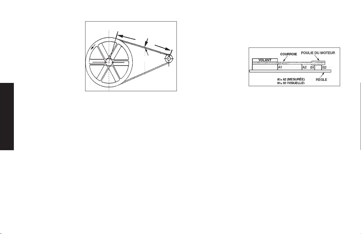
2. Serrez les deux vis de
fixation externes du
moteur juste assez
pour maintenir le
moteur en place et
pour permettre la
vérification de
l’alignement de la
poulie et du volant.
3. La courroie devrait
avoir une déflexion de
4,8 mm (3/16 po) au
milieu, entre la poulie et le volant, quand un poids de 2,26 kg
(5 lb) est appliqué au point de mi-chemin.
4. Une fois que la bonne tension de courroie est obtenue,
serrez les quatre vis de fixation du moteur. Couple à 27,1–
33,9Nm (20–25 livres-pied.).
REMARQUE : Une fois que la poulie du moteur a été déplacée
Français
de sa position d’origine réglée à l’usine, les rainures du volant et
de la poulie doivent être alignées jusqu’à 1,6 mm (1/16 po) pour
éviter une usure excessive de la courroie. Vérifiez l’alignement en
exécutant la procédure suivant d’alignement de la poulie et du
volant-moteur.
Force descendante
Déflexion
Alignement de la poulie et du volant-moteur
Une fois que la poulie du moteur a été déplacée de sa position
d’origine réglée à l’usine, les rainures du volant et de la poulie
doivent être alignées jusqu’à 1,6mm (1/16 po) pour éviter une usure
excessive de la courroie.
Le volant et la poulie du compresseur d’air doivent être alignés
(sur un même plan) jusqu’à 1,6 mm (1/16 po pour assurer que
la courroie repose bien dans les rainures du volant. Pour vérifier
l’alignement, suivez les étapes suivantes :
1. Placez le levier Auto/Off à la position « Off » , débranchez l’unité
et libérez tout l’air pressurisé du réservoir d’air.
2. Retirez le garde-courroie.
3. Placez une règle sur
l’extérieur du volant et
de la poulie du moteur.
4. Mesurez la distance
entre le rebord de la
courroie et la règle
aux points A1 et A2
de l’illustration. La différence entre les mesures ne doit pas
dépasser 1,6mm (1/16 po).
5. Si la différence est supérieure ou inférieure à 1,6mm (1/16 po),
desserrez la vis de fixation fixant la poulie du moteur à l’arbre
et réglez la position de la poulie sur l’arbre jusqu’à ce que les
mesures A1 et A2 ne soient plus qu’à 1,6mm (1/16 po) l’une de
l’autre.
6. Resserrez la vis de fixation de la poulie du moteur.
7. Effectuez une inspection visuelle de la poulie du moteur pour
vous assurer qu’elle est bien perpendiculaire à l’arbre moteur.
Les points B1 et B2 de l’illustration devraient sembler égaux.
S’ils ne le sont pas, desserrez la vis de fixation de la poulie du
moteur et égalisez les points B1 et B2 en vous assurant de ne
pas nuire à l’alignement de la courroie que vous avez effectué
à l’étape2.
8. Resserrez la vis de fixation de la poulie du moteur. Couple à
7,9-11,3Nm (70-100 in-lbs).
9. Remettez en place le garde-courroie.
48
Page 49

Soupapes d’admission et d’échappement de
la pompe du compresseur d’air
Une fois par année, faites appel à un technicien qualifié pour vérifier
les soupapes d’admission et d’échappement de la pompe du
compresseur d’air.
Inspection des conduites d’air et des
raccords pour des fuites
1. Placez le levier Auto/Off à la position « Off » , débranchez l’unité
et libérez tout l’air pressurisé du réservoir d’air.
2. Appliquez une solution savonneuse à tous les raccords,
connexions et tuyaux des conduites d’air.
3. Éliminez toutes les fuites trouvées.
IMPORTANT: Même des fuites mineures peuvent forcer le
compresseur d’air à travailler trop fort, entraînant ainsi une panne
prématurée ou un rendement médiocre.
Boulons de la tête du compresseur - serrage
Les boulons de la tête du compresseur doivent être maintenus à
un couple de serrage approprié. Vérifiez le couple de serrage des
boulons après les cinq premières heures d’utilisation. Resserrez au
besoin. Couple à 18,9-21,7Nm (14-16pi-lbs.).
Réparations et Réglages
TOUT ENTRETIEN OU TOUTE RÉPARATION NONMENTIONNÉS
ICI DOIVENT ÊTRE EFFECTUÉS PAR UN TECHNICIEN QUALIFIÉ.
AVERTISSEMENT : Risque d’utilisation dangereuse. L’appareil
commence automatiquement à fonctionner lorsqu’il est mis en
marche. Lors de l’entretien, vous pourriez vous exposer à des
sources de tension, d’air comprimé ou à des pièces en mouvement.
Des blessures pourraient ainsi survenir. Avant de faire tout entretien
ou toute réparation, débranchez la source d’alimentation du
compresseur et laissez s’échapper toute la pression d’air.
Remplacement ou nettoyage de la soupape de
retenue
1. Laissez s’échapper toute la pression du réservoir. Voir Vidange
du réservoir dans la section Entretien.
2. Placez le levier Auto/Off à la position « Off » , débranchez
l’unité et libérez tout l’air pressurisé du réservoir d’air.
3. À l’aide d’une clé réglable, desserrez l’écrou du tube de
sortie au niveau du réservoir d’air et de la pompe. Éloignez
soigneusement le tube de sortie de la soupape de retenue.
4. À l’aide d’une clé réglable, desserrez l’écrou du tube de
décharge de pression au niveau du réservoir d’air. Éloignez
soigneusement le tube de décharge de pression de la soupape
de retenue.
5. À l’aide d’une clé ouverte
de 7/8 po, dévissez la
soupape de retenue (en
tournant dans le sens
contraire des aiguilles
d’une montre). Notez
l’orientation pour
l’assemblage plus tard.
6. À l’aide d’un tournevis,
poussez doucement le
disque de soupape vers
le haut et vers le bas.
REMARQUE : Le disque
de soupape devrait se déplacer librement vers le haut et vers le
bas sur un ressort qui retient le disque de soupape en position
En position ouverte, rien n'est
En position fermée, le disque est
Tournevis
visible.
visible.
Français
49
Page 50

fermée. Si cela n’est pas le cas, la soupape de retenue doit être
nettoyée ou remplacée.
7. Nettoyez ou remplacez la soupape de retenue. Utilisez un
solvant, tel qu’un décapant de peinture ou de verni, pour
nettoyer la soupape de retenue.
8. Appliquez un produit d’étanchéité sur les filets de la soupape
de retenue. Réinstaller la soupape (en tournant dans le sens
des aiguilles d’une montre).
9. Remettez en place le tube de décharge de pression et serrez
les écrou.
10. Remettez en place le tube de sortie et serrez les écrous.
11. Effectuez la procédure de rodage. Voir la partie intitulée
Procédures de rodage de la section sur l’utilisation.
Service d’entretien additionnel
Le démontage ou un entretien du compresseur d’air au-delà de
ce qui est indiqué dans ce guide ne sont pas recommandés. Si un
entretien plus poussé est requis, communiquez avec le Centre de
Français
service sous garantie autorisé le plus proche.
Accessoires
Les accessoires recommandés pour votre outil peuvent être achetés
auprès du distributeur local ou d’un centre de réparation agréé. Si
vous avez besoin d’assistance pour trouver un accessoire pour votre
outil, veuillez composer le 1-888-895-4549 ou visiter notre site Web
à www.dewalt.com.
AVERTISSEMENT : l’utilisation de tout autre accessoire non
recommandé avec cet outil pourrait s’avérer dangereuse. Utiliser uniquement des accessoires de classement égal ou supérieur à celui de
la compresseur d’air.
Information sur les réparations
Veuillez recueillir les informations suivantes pour tous les appels au
Service à la clientèle :
Numéro du modèle ____________ Numéro de série _____________
Date et lieu de l’achat _____________________________________
Réparations
Pour assurer la SÉCURITÉ et la FIABILITÉ du produit, les réparations, l’entretien et les réglages doivent être réalisés par un centre de
réparation en usine DeWALT, un centre de réparation agréé DeWA LT
ou par d’autres techniciens qualifiés. Toujours utiliser des pièces de
rechange identiques.
Garantie limitée
Les outils industriels DEWALT sont garantis à partir de la date
d’achat.
Garantie limitée de DEUX (2) ANS sur tous les compresseurs
lubriés à l’huile
Garantie limitée d’UN (1) AN sur tous les compresseurs sans
huile. Cette garantie n’est pas transférable à une tierce partie.
DEWALT réparera ou remplacera, à ses frais, à la discrétion de
DEWALT, tout défaut pour vice de matière ou de fabrication. Pour
toute information complémentaire relative à la couverture de la
garantie et aux réparations prises en charge par celle-ci, veuillez
appeler le 1-(888)-895-4549 ou vous rendre sur le site dewalt.
com. Cette garantie ne s’applique pas aux accessoires, ou à tout
dommage causé par des réparations effectuées ou tentées par un
tiers. Cette garantie ne s’applique pas aux marchandises vendues
par DEWALT qui ont été fabriquées par une autre compagnie, et
identiées comme telles, comme l’essence pour les moteurs. La
garantie de son fabricant, si existante, sera alors applicable. TOUT
DOMMAGE, PERTE OU DÉPENSE ACCESSOIRE, INDIRECT
50
Page 51

OU IMMATÉRIEL POUVANT RÉSULTER DE TOUT DÉFAUT,
DÉFAILLANCE OU DYSFONCTIONNEMENT DU PRODUIT
N’EST PAS COUVERT PAR CETTE GARANTIE. Certains états
n’autorisent aucune exclusion ou limitation de garantie contre tout
préjudice accessoire ou indirect, aussi il se peut que la limitation ou
l’exclusion susdite ne vous soit pas applicable. TOUTE GARANTIE
IMPLICITE, Y COMPRIS DE QUALITÉ MARCHANDE OU
D’ADÉQUATION DANS UN BUT PARTICULIER, EST LIMITÉE À
UN AN À COMPTER DE LA DATE D’ACHAT.
Certains états n’autorisent aucune limitation quant à la durée de
toute garantie implicite, aussi il se peut que l’exclusion susdite ne
vous soit pas applicable. Cette garantie confère des droits légaux
particuliers à l’acheteur, mais celui-ci pourrait aussi bénécier
d’autres droits variant d’un territoire à l’autre.
Ce à quoi la Société s’engage : (la société) s’engage à couvrir les
pièces et la main-d’œuvre requises an de remédier aux défauts
importants constatés dans les matériaux ou dans la main-d’œuvre
au cours de la première année suivant l’acquisition, sous réserve de
ce qui suit. Les pièces utilisées pour la réparation des unités complètes ou des accessoires sont garanties pendant ce qui reste de la
période de garantie initiale.
Qu’est-ce qui n’est pas couvert par cette garantie? L’incapacité
de l’acheteur au détail initial d’installer, d’entretenir et d’exploiter cet
équipement conformément aux pratiques industrielles normales. Les
modications apportées au produit ou le bricolage effectué sur ses
composants, ou le manquement à se conformer aux recommandations spéciques de la Société énoncées dans le manuel de l’utilisateur, rendront cette garantie nulle et non avenue. La Société rejette
toute responsabilité pour les réparations, remplacements ou ajustements à l’équipement ou pour tous coûts reliés au travail effectués
sur l’équipement par l’acheteur sans l’autorisation préalable écrite
de la Société. Les effets de la corrosion, de l’érosion, des conditions
environnementales ambiantes, des défauts de nature supercielle et
les matériaux requis pour la maintenance de routine sont expressément exclus de cette garantie. Les matériaux requis pour la maintenance de routine tels que l’huile, les lubriants et les ltres à air, ainsi
que les changements d’huile, de ltres à air, de tension de courroie,
etc. font partie de la responsabilité de l’utilisateur. Parmi les exclusions supplémentaires, il faut ajouter les dommages liés au transport,
les défaillances liées à la négligence, aux accidents ou à une mauvaise utilisation, les moteurs à induction alimentés par un alternateur, les
fuites d’huile, les fuites d’air, la consommation d’huile, les raccords
qui fuient, les boyaux, les robinets d’évacuation d’air, les soupapes
de purge et les tuyaux de transfert.
• Les composants suivants sont considérés comme des
équipements sujets à usure normale et ne sont donc
couverts que pendant un an après leur vente : courroies,
faisceaux, volants, clapets de non-retour, manostats,
déchargeurs à air, manettes d’accélération, moteurs
électriques, balais, régulateurs, joints toriques,
manomètres, tubes, conduits, raccords, attaches, roues,
porte-outils à attache rapide, garnitures, joints
d’étanchéité, logements de ltre à air, segments de piston,
biellettes de liaison et joints de piston.
• Les charges de main-d’œuvre, d’appels de service et de
déplacements ne sont pas couvertes au-delà de la
première année suivant l’acquisition pour les compresseurs
xes (compresseurs sans poignées et sans roues). Les
réparations nécessitant des heures supplémentaires, des
taux et tarifs de n de semaine ou toute autre charge excé
dant le tarif standard de travail en atelier ne sont pas
couvertes.
• Temps requis pour la formation d’orientation an de
permettre au centre de service d’obtenir accès au produit,
Français
51
Page 52

ou du temps supplémentaire pour cause de sortie
inadéquate.
• Les dommages causés par une tension incorrecte, un
câblage inapproprié ou l’installation du compresseur par
quelqu’un d’autre qu’un électricien professionnel agréé
rendront la garantie nulle et non avenue.
• Les dommages causés par un entretien inadéquat du ltre.
• L’usure de la pompe ou l’endommagement d’une valve
causé par l’emploi d’un lubriant contre-indiqué.
• L’usure de la pompe ou un dommage causé par une
contamination d'huile.
• L’usure de la pompe ou l’endommagement d’une valve
causé par le non-respect des directives d’entretien
correctes.
• L’utilisation sans huile ou avec un niveau d’huile insufsant.
• Les moteurs à essence, si le produit est équipé d’un tel
moteur : se reporter au manuel d’utilisation du moteur pour
la couverture de la garantie spécique du fabricant du
Français
moteur.
Pièces achetées séparément : la garantie pour les pièces achetées
séparément, telles que les pompes, les moteurs, etc. s’applique
comme suit :
À compter de la date d’achat
• Toutes les pompes à un étage ou à deux étages 1 an
• Moteurs électriques 90 jours
• Moteur/pompe universel(le) 30 jours
• Toute autre pièce 30 jours
• Aucune autorisation de retour ne sera accordée pour les
composants électriques une fois qu’ils sont installés.
Comment obtenir du service? An d'être admissible au service
sous garantie, vous devez être l'acheteur original au détail, et de
fournir une preuve d'achat de l'un des concessionnaires de la société, des distributeurs ou magasins de vente au détail. Compresseurs
portatifs ou des pièces doivent être livrées, ou expédiés, au Centre
de service agréé le plus proche. Tous les frais de transport et les
frais associés de voyage doivent être pris en charge par le consommateur. S'il vous plaît appelez notre numéro sans frais 1-888-8954549 pour une assistance.
CETTE GARANTIE VOUS ACCORDE DES DROITS LÉGAUX
SPÉCIFIQUES ET VOUS POUVEZ BÉNÉFICIER D’AUTRES DROITS
EN FONCTION DE L’ÉTAT OÙ CELLE-CI S’APPLIQUE.
LA SOCIÉTÉ N’OFFRE AUCUNE AUTRE GARANTIE NI
REPRÉSENTATION DE QUELQUE SORTE QUE CE SOIT,
EXPRESSE OU IMPLICITE, EXCEPTION FAITE DE LA PROPRIÉTÉ.
TOUTES LES GARANTIES IMPLICITES, EN PARTICULIER TOUTE
GARANTIE DE COMMERCIALISATION ET D’ADÉQUATION À UN
USAGE PARTICULIER, SONT REJETÉES PAR LA PRÉSENTE.
TOUTE RESPONSABILITÉ POUR DES DOMMAGES INDIRECTS
ET CORRESPONDANT À L’UNE QUELCONQUE DES GARANTIES
ET À L’ENSEMBLE DE CELLES-CI, À D’AUTRES CONTRATS, À
LA NÉGLIGENCE OU À D’AUTRES DÉLITS CIVILS, EST EXCLUE
CONFORMÉMENT AUX CLAUSES D’EXCLUSION DE LA LOI.
52
Page 53

REMPLACEMENT GRATUIT DES ÉTIQUETTES
D’AVERTISSEMENT : si les étiquettes d’avertissement deviennent
illisibles ou sont manquantes, composer le 1-888-895-4549 pour en
obtenir le remplacement gratuit.
Glossaire
CFM : Pieds cubes par minute ; une unité de mesure de débit d’air.
SCFM : pied cube par minute (standard), une unité de mesure du
soufflage.
PSI : livres par pouce carré, une unité de mesure de pression.
Pression d’enclenchement: Point de pression bas réglé en usine
qui met en marche le moteur de la pompe pour remettre sous
pression l’air dans le réservoir.
Pression de déclenchement: Point de pression haut réglé en
usine qui arrête le moteur de la pompe et la hausse de pression
dans le réservoir au-delà d’un certain niveau.
Bien aéré: Qualifie un endroit où les gaz d’échappement ou les
vapeurs sont remplacés par de l’air frais.
Circuit réservé: Circuit électrique réservé exclusivement au compresseur d’air.
ASME: American Society of Mechanical Engineers (Société américaine des ingénieurs mécaniciens). Indique que les composants
sont fabriqués, testés et examinés selon les normes définies par
l’ASME.
CSA: L’association canadienne de normes
Indique que les produits qui font avoir examinée cette inscription avoir été fabriquée, testée et aux normes qui sont
fixées par CSA.
L’association canadienne de normes (Etats-Unis) Indique
que les produits qui font avoir fabriqué cette inscription,
testé et examiné aux normes qui sont fixées par CSA.
Ces produits se conforment également à la norme 1450
d’cU.l..
Code Californien : l’appareil pourrait être conforme au code de la
Californie462(l)(2)/(M) (2). L’étiquettedespécifications/modèle
est apposée sur le côté du réservoir d’air des appareils qui sont
conformes au code californien.
Français
53
Page 54

Guide de dépannage
Cette section énumère les défaillances les plus communes, leurs causes et les mesures correctives. L’opérateur ou le personnel d’entretien peut
exécuter certaines mesures correctives, d’autres exigent l’assistance d’un technicien DeWALT qualifié ou du distributeur.
Problème Code
Fuites d’air .............................................................................................................................................. 1
Fuites d’air dans le réservoir d’air ou dans les soudures du réservoir d’air .......................................2
Fuites d’air entre la tête et la plaque porte-soupapes .........................................................................3
Fuites d’air à la soupape de sûreté .......................................................................................................4
Le compresseur ne fournit pas la quantité d’air requise pour le fonctionnement d’accessoires .....1, 5, 6, 7, 9, 10
Admission d’air restreinte. ....................................................................................................................9
Huile dans l’air évacué ............................................................................................................................9, 19, 31
Cliquetis ................................................................................................................................................... 4, 10, 11, 12, 13, 14
Usure excessive de la courroie ............................................................................................................ 10, 11, 14, 15
Sifflement ................................................................................................................................................ 10
Humidité présente dans le carter de la pompe ..................................................................................1, 3, 8, 17, 18, 19, 20, 21, 22
Français
Appel de courant excessif ......................................................................................................................14, 26, 27
Le compresseur ne démarre pas quand il fait froid..............................................................................17, 34, 35
Le relevé de pression sur le manomètre réglementé chute lorsque l’accessoire est utilisé ..............23
Fuite d’air continuelle au bouton du régulateur .................................................................................... 24
Le régulateur ne parvient pas à fermer la sortie d’air ........................................................................... 24
Pression du réservoir d’air ne se développe pas ............................................................................... 25
Le compresseur cale .............................................................................................................................. 28, 29, 30
Surchauffe ...............................................................................................................................................27, 32, 33
54
Page 55

Codes de dépannage
CODE CAUSE POSSIBLE POSSIBLE SOLUTION
1 Les raccords de tube ne sont pas assez serrés Serrer les raccords qui émettent un sifflement de fuite
d’air. Contrôler les raccords avec une solution d’eau
savonneuse. NE SERREZ PAS TROP.
2 Réservoir d’air défectueux Le réservoir d’air doit être remplacé. Ne pas réparer la
fuite.
AVERTISSEMENT : Risque d’éclatement. Ne pas percer
le réservoir d’air, ni le souder ou le modifier de quelque
manière qui soit. Ces interventions l’affaibliront. Le réservoir risque de rompre ou d’exploser.
3 Joints d’étanchéité fuyants Communiquer avec un centre de réparation en usine de
DeWALT ou un centre de réparation agréé DeWALT.
4 Soupape de sûreté défectueuse Faites fonctionner la soupape manuellement en tirant sur
la bague. Si la soupape fuit toujours, la remplacer.
5 Utilisation excessive prolongée de l’air Diminuer la quantité d’air utilisée.
6 Le compresseur ne dispose pas de la capacité adéquate
pour l’utilisation d’accessoires
7 Trou dans le boyau Vérifiez et remplacez-le au besoin.
8 L’appareil fonctionne dans des conditions humides ou
fraîches
9 Filtre d’admission d’air obstrué Nettoyer ou remplacer le filtre d’admission d’air.
10 Courroie lâche Contrôler la tension de la courroie, consulter la rubrique
Vérifier les exigences d’air de l’accessoire. Si elles sont
supérieures au CFM ou à la pression fournie par le com-
presseur d’air, un compresseur de plus grande capacité
est requis pour l’utilisation de l’accessoire.
Déplacer l’appareil dans un endroit sec bien aéré.
Réglage de la tension de la courroie sous Entretien.
Français
55
Page 56

CODE CAUSE POSSIBLE POSSIBLE SOLUTION
Français
11 Poulie lâche Serrer les vis de calage de la poulie à un couple de
9,6 à
10,2 Nm (85 à 90 po-lb).
12 Volant lâche Serrer la vis du volant à un couple de 20,0 à 24,4 Nm
(14 à 18 pi-lb).
13
Accumulation de carbone dans la pompe Communiquer avec un centre de réparation en usine de
DeWALT ou un centre de réparation agréé DeWALT.
14
Courroie trop serrée Contrôler la tension de la courroie, consulter la rubrique
Réglage de la tension de la courroie sous Entretien.
15
Mauvais alignement de la poulie Consulter la rubrique Alignement de la poulie-moteur/
volant sous Entretien.
16
Huile de la pompe est faible Ajouter à la pompe un mélange d’huiles synthétiques sans
détergent pour compresseur d’air. Consulter la rubrique
Huile de la pompe du compresseur sous Entretien.
17
Utilisation d’huile détergente dans la pompe Vidanger l’huile et recharger la pompe avec un mélange
d’huiles synthétiques sans détergent pour compresseur
d’air.
18
Cycles de travail extrêmement léger Utiliser l’appareil pour des cycles de travail plus prolongés.
On recommande de l’utiliser à plein régime de 50 % à 75 %
de son temps de fonctionnement et au ralenti pour les
autres 25 %.
19
Segments de pistons endommagés ou usés Communiquer avec un centre de réparation en usine de
DeWALT ou un centre de réparation agréé DeWALT.
20
Cylindre ou piston endommagé ou usé Communiquer avec un centre de réparation en usine de
DeWALT ou un centre de réparation agréé DeWALT.
56
Page 57

CODE CAUSE POSSIBLE POSSIBLE SOLUTION
21
Fini du cylindre du compresseur est usé Communiquer avec un centre de réparation en usine de
DeWALT ou un centre de réparation agréé DeWALT.
22
Eau présente dans l’huile de la pompe Vidanger l’huile et recharger la pompe avec un mélange
d’huiles synthétiques sans détergent pour compresseur
d’air.
23
Le régulateur n’est pas réglé correctement pour
l’accessoire utilisé
Il est normal que la pression chute lorsqu’un accessoire
est utilisé, ajuster le régulateur comme indiqué sous
Caractéristiques si la pression chute trop.
REMARQUE : Régler la pression régulée sous des condi-
tions de travail avec l’utilisation de l’accessoire.
24 Le régulateur est endommagé Le remplacer.
26
Tension insuffisante/surcharge
du moteur
Vérifiez que l’alimentation est adéquate et que le
compresseur est
branché sur un circuit séparé. Vérifiez que le compresseur
est
branché sur son propre circuit. Si une rallonge est utilisée,
essayez sans utiliser la rallonge. Si le compresseur est
branché sur un circuit protégé par un fusible, utilisez des
fusibles temporisés à double élément (Buss Fusetron de
type «T» seulement).
27
Passages d’air colmatés Inspectez et remplacez les tubes de transfert ou la soupape
d’arrêt, selon les besoins.
28
29
30
Tension insuffisante vers le moteur Fournissez une puissance adéquate.
Soupape d’arrêt défectueuse Remplacez la soupape d’arrêt.
Grippage de la pompe Communiquer avec un centre de réparation en usine de
DeWALT ou un centre de réparation agréé DeWALT.
Français
57
Page 58

CODE CAUSE POSSIBLE POSSIBLE SOLUTION
31
Niveau d’huile trop élevé Ramenez au niveau correct. Consulter la rubrique Huile de
la pompe du compresseur sous Entretien.
32
Mauvaise aération Placez le compresseur dans un endroit frais, sec et bien
aéré, à une distance de 30 cm (12 po.) du mur le plus
proche.
33
34
Surfaces de refroidissement sales Nettoyez entièrement toutes les surfaces de refroidissement.
Trop de pression de refoulement dans le réservoir Ouvrez le robinet de purge quand vous mettez en marche
le moteur.
35
Le compresseur est trop froid Placez le compresseur dans un endroit plus chaud.
Français
58
Page 59
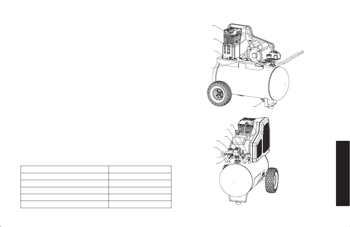
Compresor de aire
A.
Filtro de entrada de aire de la bomba
B. Interruptor ENCENDIDO [AUTO(-)] / Off (APAGADO(O)]
C.
Manómetro del tanque de aire
D.
Manómetro regulado
E. Pressure Regulator
F.
Regulador de presión
G.
Válvula de seguridad
H.
Válvula de drenaje del tanque de aire
I.
Varilla para medición del nivel de aceite de la bomba/Tapón de
llenado de aceite
J.
Tapón de drenaje de aceite de la bomba
K. Válvula reguladora
L. Conexión rápida
Especicaciones de la bomba
2 Cilindros
Etapa sencilla
Lubricación con aceite
Cilindro de la caja del motor de hierro fundido y cabezal de
aluminio
Peso: 18,6 kg (41 lbs.)
Capacidad de aceite: 887 ml (16 onzas)
Especicaciones
MODELO
PESO
ALTURA
ANCHO
CAPACIDAD DEL TANQUE DE AIRE
PRESIÓN APROXIMADA DE ALIVIO
DXCMPA1982054
165 lbs. (75 kg)
33.625” (854.1 mm)
34.188” (868.4 mm)
20 gallons (75,7 liters)
175 psi
59
A
I
J
K
H
C
G
B
D
F
L
E
Español
Page 60
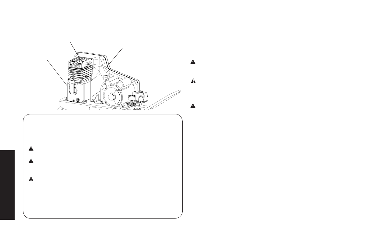
Supercies calientes
CILINDROYCABEZALDE
LABOMBA
CAJADELMOTOR
DELABOMBA
Definiciones: Normas de seguridad
Las siguientes definiciones describen el nivel de gravedad de
cada advertencia. Lea el manual y preste atención a estos
símbolos.
PELIGRO: Indica una situación de peligro inminente que,
si no se evita, provocará la muerte o lesiones graves.
ADVERTENCIA: Indica una situación de peligro potencial
que, si no se evita, podría provocar la muerte o lesiones
graves.
ATENCIÓN: Indica una situación de peligro potencial que,
si no se evita, puede provocar lesiones leves o moderadas.
AVISO: Se refiere a una práctica no relacionada a lesiones
Español
corporales que de no evitarse puede resultar en daños a la
propiedad.
TUBODESALIDA
FIG. 2
SI TIENE ALGUNA PREGUNTA O ALGÚN COMENTARIO
QUE HACER CON RESPECTO A ESTA O CUALQUIER
OTRA HERRAMIENTA DeWALT, LLÁMENOS SIN CARGO AL:
1-888-895-4549
Instrucciones de seguridad importantes
ADVERTENCIA: No opere esta unidad hasta que haya leído y
comprendido este manual de instrucciones de seguridad, operación
y mantenimiento.
ADVERTENCIA: Este producto contiene sustancias químicas,
reconocidas por el Estado de California como causantes de cáncer,
defectos de nacimiento u otros problemas reproductivos. Lávese
las manos después de utilizarlo.
ADVERTENCIA: Algunos tipos de polvo contienen sustancias
químicas, como el amianto y el plomo de las pinturas de base
plomo, reconocidas por el Estado de California como causantes de
cáncer, defectos de nacimiento u otros problemas reproductivos.
60
Page 61

GUARDE ESTAS INSTRUCCIONES
PELIGRO: RIESGO DE EXPLOSIÓN O INCENDIO
¿QUÉ PUEDE SUCEDER? CÓMO EVITARLO
• Es normal que los contactos
eléctricos dentro del motor y el
interruptor de presión
produzcan chispas.
• Si las chispas eléctricas del
compresor entran en contacto
con vapores inflamables,
pueden encenderse,
provocando un incendio o una
explosión.
• Restringir cualquiera de las
aberturas de ventilación del
compresor puede producir un
sobrecalentamiento grave y
podría provocar un incendio.
• Opere siempre el compresor en
un área bien ventilada libre de
materiales combustibles,
gasolina o vapores de
solventes.
• Si se pulverizan materiales
inflamables, ubique el
compresor al menos a 6,1 m
(20 pies) del área de
pulverización. Se puede
necesitar manguera adicional.
• Guarde los materiales
inflamables en lugar seguro lejos
del compresor.
• Nunca coloque objetos contra o
sobre la bomba del compresor.
• Opere el compresor en un lugar
abierto con una distancia de
al menos 30,5 cm (12 pulg.) a
cualquier pared u obstrucción
que pudiera restringir el flujo de
aire fresco a las aberturas de
ventilación.
• Opere el compresor en un área
limpia, seca y bien ventilada.
No opere la unidad dentro de la
casa o en un área muy cerrada.
• El funcionamiento sin atención
de este producto podría
provocar lesiones personales
o daños a la propiedad. Para
disminuir el riesgo de incendio,
no permita que el compresor
funcione sin que alguien lo
controle.
• Permanezca siempre
controlando el producto cuando
está en funcionamiento.
• Siempre apague y desenchufe
la unidad cuando no esté en
uso.
PELIGRO: RIESGO RESPIRATORIO (ASFIXIA)
¿QUÉ PUEDE SUCEDER? CÓMO EVITARLO
• El aire comprimido que sale
de su compresor no es seguro
para respirarlo. El flujo de aire
puede contener monóxido
de carbono, vapores tóxicos
o partículas sólidas del
tanque de aire. Respirar
estos contaminantes puede
• El aire que se obtiene
directamente del compresor
no se debe usar nunca
para consumo humano. El
compresor no incluye equipo
de seguridad en línea y filtros
adecuados para consumo
humano.
provocar lesiones graves o la
muerte.
Español
61
Page 62

•
La exposición a productos
químicos en el polvo
producido por las
herramientas eléctricas
al lijar, aserrar, esmerilar,
taladrar y otras actividades
de la construcción puede ser
peligrosa.
•
Los materiales pulverizados
como pintura, solventes
para pinturas, removedor
de pintura, insecticidas y
herbicidas pueden contener
vapores dañinos y venenos.
Español
•
Trabaje en un área con buena
ventilación cruzada. Lea y siga
las instrucciones de seguridad
que se proveen en la etiqueta
o en la ficha técnica de los
materiales que está utilizando.
Siempre utilice equipamiento
de seguridad certificado:
protección respiratoria
aprobada por NIOSH/OSHA o
una mascarilla facial adecuada
diseñada para usar para los
fines que usted requiere.
PELIGRO: RIESGO DE EXPLOSIÓN
Tanque de aire: El 26 de febrero de 2002, la Comisión de Seguridad para
Productos de Consumo delos Estados Unidos publicó el Comunicado
# 02-108 sobre la seguridad en los tanques de compresores de aire:
Los tanques receptores de los compresores de aire no tienen
una vida útil infinita. La vida útil del tanque depende de diversos
factores, incluyendo las condiciones de operación, las condiciones
ambientales, la instalación debida del mismo, modificaciones
realizadas en el campo y el nivel de mantenimiento que reciba. Es
difícil prever cuál será el efecto exacto de estos factores sobre la vida
útil del tanque receptor de aire.
Si no se siguen procedimientos de mantenimiento debidos, la
corrosión interna de la pared interior del tanque receptor de aire
puede causar una ruptura imprevista en el tanque de aire, lo que
hará que el aire presurizado escape con fuerza y repentinamente,
pudiendo lesionar al usuario.
El tanque de su compresor de aire debe ser dado de baja al final del
año que aparece en la etiqueta de advertencia de su tanque.
Las siguientes condiciones pueden llevar a debilitar el tanque de aire
y ocasionar la explosión violenta del mismo:
¿QUÉ PUEDE SUCEDER? CÓMO EVITARLO
• No drenar correctamente el
agua condensada del tanque
de aire, que provoca óxido y
adelgazamiento del tanque de
aire de acero.
• Drene el tanque diariamente o
luego de cada uso. Si un tanque
de aire presenta una pérdida,
reemplácelo inmediatamente con
un tanque nuevo o reemplace
todo el compresor.
62
Page 63

• Modificaciones o intento de
reparación del tanque de aire.
• Las modificaciones no
autorizadas de la válvula de
seguridad o cualquier otro
componente que controle la
presión del tanque.
Elementos y accesorios:
• Exceder las indicaciones de
presión para las herramientas
neumáticas, las pistolas
pulverizadoras, los accesorios
neumáticos, los neumáticos y
otros artículos inflables puede
hacer que exploten o revienten,
y puede provocar lesiones
graves.
• Nunca perfore, suelde o haga
ninguna modificación al tanque
de aire o a sus elementos. Nunca
intente reparar un tanque de
aire dañado o con pérdidas.
Reemplácelo con un tanque de
aire nuevo.
• El tanque está diseñado para
soportar determinadas presiones
de operación. Nunca realice
ajustes ni sustituya piezas
para cambiar las presiones de
operación fijadas en la fábrica.
• Siga la recomendación del
fabricante del equipo y nunca
exceda el nivel máximo de
presión aceptable para los
elementos. Nunca utilice el
compresor para inflar objetos
pequeños de baja presión, tales
como juguetes de niños, pelotas
de fútbol o de basquetbol, etc.
Neumáticos:
• El inflado excesivo de los
neumáticos podría causar
lesiones graves y daño a la
propiedad.
• Utilice un medidor de presión
de neumáticos para controlar la
presión de éstos antes de cada
uso y mientras los infla; observe
el flanco para ver la presión
correcta del neumático.
NOTA:
Los tanques de aire, los
compresores y el equipo similar
que se usa para inflar neumáticos
pueden llenar neumáticos
pequeños como éstos con mucha
rapidez. Ajuste el regulador de
presión en el suministro de aire
a un valor que no supere el de la
presión del neumático. Agregue
aire en forma gradual y use
con frecuencia el medidor de
presión de neumáticos para evitar
inflarlos.
Español
63
Page 64
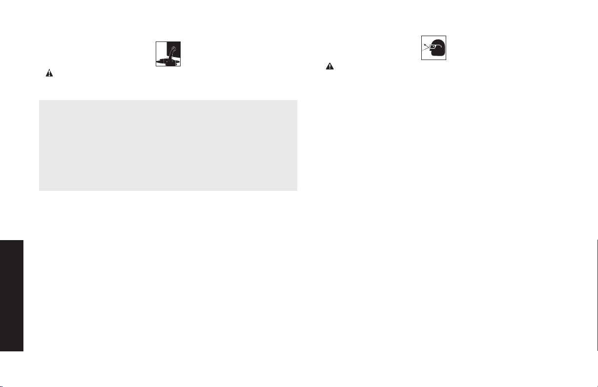
PELIGRO: RIESGO DE LESIÓN O DAÑO A LA PROPIEDAD AL
TRANSPORTAR O ALMACENAR LA UNIDAD
¿QUÉ PUEDE SUCEDER? CÓMO EVITARLO
• Se puede producir una pérdida
o derrame de aceite, lo que
podría provocar peligro de
incendio o inhalación, lesiones
graves o la muerte. Los
derrames de aceite dañarán
alfombras, pintura u otras
superficies de vehículos o
remolques.
Español
• Coloque siempre el compresor
en un tapete protector cuando
lo transporte, para proteger al
vehículo de daños por pérdidas.
Retire inmediatamente el
compresor del vehículo una
vez que haya llegado a destino.
Mantenga siempre el compresor
nivelado y nunca lo coloque de
costado.
ADVERTENCIA: RIESGO DE OBJETOS DESPEDIDOS
¿QUÉ PUEDE SUCEDER? CÓMO EVITARLO
• La corriente de aire comprimido
puede provocar lesiones en
los tejidos blandos de la piel
expuesta y puede impulsar
suciedad, astillas, partículas
sueltas y objetos pequeños a
gran velocidad, que pueden
producir daños en la propiedad
y lesiones personales.
• Utilice siempre equipo de
seguridad certificado: anteojos
de seguridad ANSI Z87.1(CAN/
CSA Z94.3) con protección lateral
al usar el compresor.
• Nunca apunte ninguna boquilla
ni pulverizador a ninguna parte
del cuerpo o a otras personas o
animales.
• Apague siempre el compresor y
drene la presión de la manguera
de aire y del tanque de aire antes
de intentar hacer mantenimiento,
conectar herramientas o
accesorios.
64
Page 65

ADVERTENCIA: RIESGO DE SUPERFICIES CALIENTES
¿QUÉ PUEDE SUCEDER? CÓMO EVITARLO
• Tocar metal expuesto como
el cabezal del compresor, el
cabezal del motor, el escape
del motor, o los tubos de salida
puede provocar quemaduras
graves.
• Nunca toque ninguna
parte metálica expuesta
del compresor durante o
inmediatamente después de su
funcionamiento. El compresor
continuará caliente durante
varios minutos después de su
funcionamiento.
• No toque las cubiertas
protectoras ni intente realizar
mantenimiento hasta que la
unidad se haya enfriado.
ADVERTENCIA: RIESGO DE DESCARGA ELÉCTRICA
¿QUÉ PUEDE SUCEDER? CÓMO EVITARLO
• Su compresor de aire funciona
con electricidad. Como
cualquier otro mecanismo que
funciona con electricidad, si
no se lo utiliza correctamente
puede provocar descargas
eléctricas.
• Nunca haga funcionar el
compresor al aire libre cuando
está lloviendo o en condiciones
de humedad.
• Nunca haga funcionar el
compresor sin las cubiertas de
protección o si están dañadas.
• Que personal no calificado
intente realizar reparaciones
puede provocar lesiones
graves o muerte por
electrocución.
• Puesta a tierra: La no
colocación de la puesta a
tierra adecuada para este
producto puede provocar
lesiones graves o muerte por
electrocución. Consulte las
Instrucciones de Conexión a
tierra en Instalación.
• Cualquier cableado eléctrico
o las reparaciones requeridas
para este producto deben ser
realizadas por un centro de
servicio de fábrica o un centro
de mantenimiento autorizado
de acuerdo con los códigos
eléctricos nacionales y locales.
• Asegúrese de que el circuito
eléctrico al que se conecta
el compresor suministre la
conexión a tierra adecuada, el
voltaje adecuado y el fusible de
protección adecuado.
Español
65
Page 66
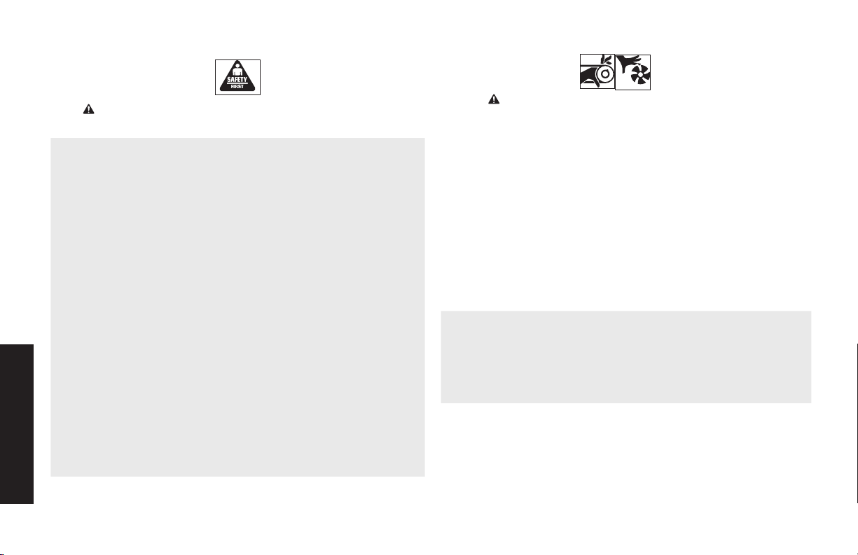
ADVERTENCIA: RIESGO DE OPERACIÓN INSEGURA
¿QUÉ PUEDE SUCEDER? CÓMO EVITARLO
• La operación insegura de
su compresor de aire podría
producir lesiones graves o la
muerte, a usted mismo o a otras
personas.
Español
• Revise y comprenda todas las
instrucciones y advertencias de
este manual.
• Familiarícese con la operación y
los controles del compresor de
aire.
• Mantenga el área de operaciones
libre de personas, mascotas y
obstáculos.
• Mantenga a los niños alejados
del compresor de aire en todo
momento.
• No opere el producto cuando
esté cansado o bajo la influencia
de alcohol o drogas. Manténgase
alerta en todo momento.
• Nunca anule las características
de seguridad de este producto.
• Equipe el área de operaciones
con un extintor de incendios.
• No opere la máquina si faltan
piezas, si éstas están rotas o si
no son las autorizadas.
• Nunca se pare sobre el
compresor.
ADVERTENCIA: RIESGO POR PIEZAS MÓVILES
¿QUÉ PUEDE SUCEDER? CÓMO EVITARLO
• Las piezas móviles como la
polea, el volante y la correa
pueden provocar lesiones
graves si entran en contacto
con usted o con sus ropas.
• Intentar hacer funcionar el
compresor con partes dañadas
o faltantes, o intentar reparar
el compresor sin las cubiertas
protectoras puede exponerlo
a piezas móviles lo que puede
provocar lesiones graves.
• Nunca haga funcionar el
compresor sin los protectores o
cubiertas o si los mismos están
dañados.
• Mantenga el cabello, la ropa y los
guantes alejados de las piezas en
movimiento. Las ropas holgadas,
las joyas o el cabello largo
pueden quedar atrapados en las
piezas móviles.
• Los orificios de ventilación
pueden cubrir piezas en
movimiento, por lo que también
se deben evitar.
• Cualquier reparación requerida
por este producto debe ser
realizada por un centro de
servicio de fábrica DeWALT o
un centro de servicio autorizado
DeWALT.
66
Page 67
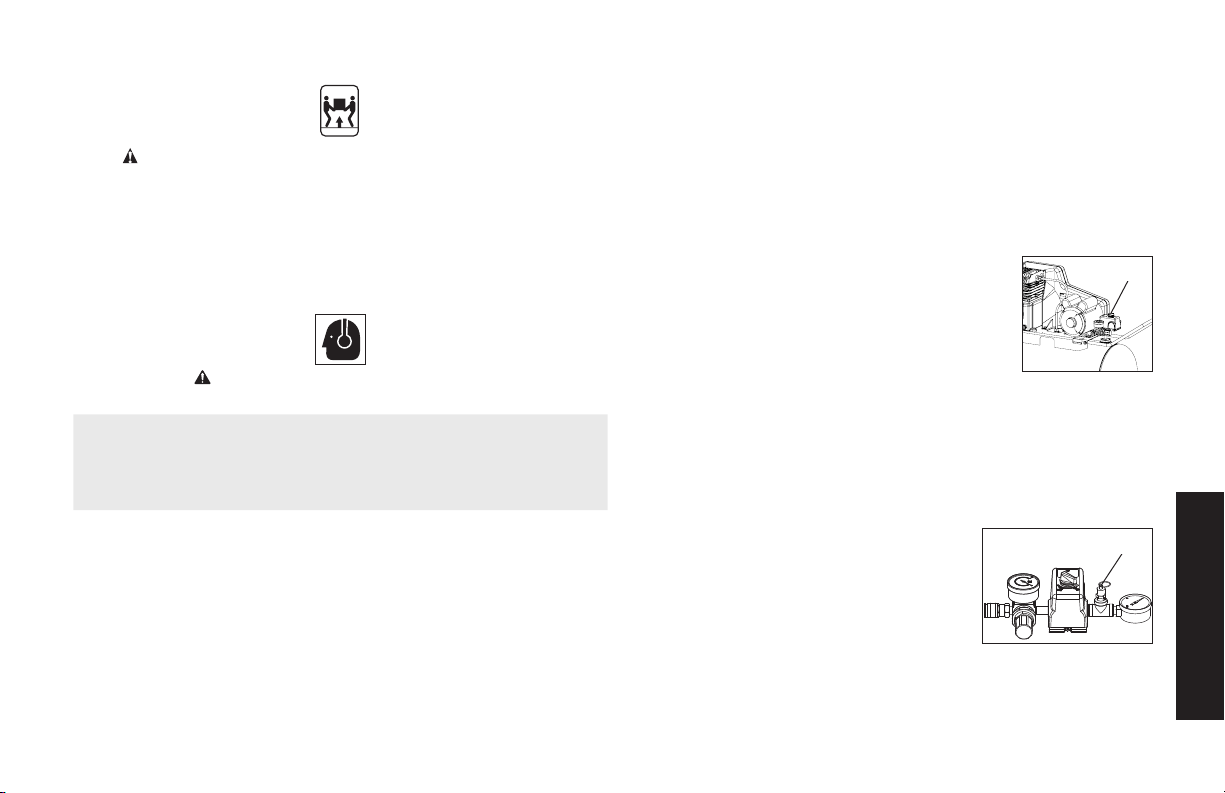
ADVERTENCIA: RIESGO DE LESIÓN POR LEVANTAR
¿QUÉ PUEDE SUCEDER? CÓMO EVITARLO
• El intento de levantar un objeto
muy pesado puede provocar
lesiones graves.
ATENCIÓN: RIESGO POR RUIDOS
¿QUÉ PUEDE SUCEDER? CÓMO EVITARLO
• En determinadas condiciones
y según el período de uso,
el ruido provocado por este
producto puede originar
pérdida de audición.
MUCHO PESO
• El compresor es demasiado
pesado como para que lo
levante una sola persona.
Consiga ayuda de otras personas para levantarlo.
• Utilice siempre equipo
de seguridad certificado:
protección auditiva ANSI S12.6
(S3.19).
SAVE THESE INSTRUCTIONS FOR FUTURE
USE
CONOZCA SU COMPRESOR DE AIRE
LEA ESTE MANUAL DEL PROPIETARIO Y SUS NORMAS DE
SEGURIDAD ANTES DE OPERAR LA UNIDAD. Compare las
ilustraciones contra su unidad a fin de familiarizarse con la ubicación
de los distintos controles y regulaciones. Conserve este manual
para referencias futuras.
CARACTERÍSTICAS (Fig. 1)
NTERRUPTOR DE AUTO (-) / APAGADO (O)
Coloque este interruptor (B) en la posición Encendido
(AUTO) (-) para suministrar energía automática al
interruptor de presión y en Apagado (OFF) (O) para
cortar la energía al final de cada uso. NOTA:
SIEMPRE asegúrese de que el interruptor (B) esté en
la posición de apagado (OFF) (O) antes de retirar o
reemplazar la cubierta del interruptor de presión.
INTERRUPTOR DE PRESIÓN
El interruptor de presión (B) arranca automáticamente el motor
cuando la presión del tanque de aire cae por debajo de la presión
de arranque fijada en fábrica. Detiene el motor cuando la presión del
tanque de aire alcanza la presión de corte fijada en fábrica.
VÁLVULA DE SEGURIDAD
Esta válvula (G) está diseñada para prevenir
fallas del sistema aliviando la presión cuando
el aire comprimido alcanza un nivel
predeterminado. La válvula está calibrada
desde fábrica y no se debe quitar ni modificar
de ninguna forma.
VÁLVULA DE CONTROL
Cuando el compresor de aire está funcionando, la válvula de control
B
G
Español
67
Page 68

(K) está abierta, permitiendo al aire comprimido
entrar al tanque de aire. Cuando el compresor de
aire alcanza la presión de corte, la válvula de control
se cierra, permitiendo que la presión de aire se
conserve dentro del tanque de aire.
FILTRO DE ENTRADA DE AIRE
El filtro (A) está diseñado para limpiar el aire que
ingresa a la bomba. Para asegurar que la bomba
reciba continuamente un suministro de aire limpio,
fresco y seco, el filtro debe estar siempre limpio y la
entrada del filtro libre de obstrucciones.
VÁLVULA DE DRENAJE DEL TANQUE DE AIRE
La válvula de drenaje (H) está ubicada en la
base del tanque de aire y se utiliza para
drenar la condensación al terminar cada
etapa de uso.
Consulte Drenar el tanque
de aire en la sección Mantenimiento.
MANÓMETRO (MEDIDOR DE PRESIÓN) DE SALIDA
El manómetro (medidor de presión) de
D
salida (D) indica la presión del aire
disponible en la salida del regulador.
Esta presión la controla el regulador y
es siempre menor que o igual a la
presión del tanque.
MANÓMETRO (MEDIDOR DE
PRESIÓN) DEL TANQUE
Español
El manómetro (medidor de presión)
del tanque (C) indica la presión de aire
L
de reserva en el tanque.
CONECTORES RÁPIDOS UNIVERSALES
K
El conector rápido universal (L) acepta los tres estilos más
populares de enchufes de conexión rápida: Industrial, para
automóviles y ARO. “Empujar para conectar” con una sola mano,
esta operación hace que las conexiones sean más simples y fáciles.
REGULADOR
A
La perilla del regulador (E) controla la presión de aire proveniente del
tanque de aire.
Ajuste del regulador:
1. Tire la perilla del regulador (E) hacia afuera.
2. Gire la perilla en sentido de las agujas del reloj para aumentar
la presión regulada y en sentido contrario a las agujas del reloj
para disminuirla.
3. Cuando la presión deseada aparezca en el manómetro regulado, empuje la perilla hacia adentro para bloquearla.
H
ADVERTENCIA:
Risque d’éclatement. Une pression d’air
trop élevée conduit à un risque dangereux d’éclatement. Vérifiez
C
la pression nominale maximum du fabricant pour tous les outils
pneumatiques et accessoires utilisés. La pression de sortie du
régulateur ne doit jamais excéder la pression nominale maximum.
BOMBA DE COMPRESIÓN DEL AIRE
Comprime el aire dentro del tanque. El aire de trabajo no se
encuentra disponible hasta que el compresor haya alcanzado a
llenar el tanque hasta un nivel de presión por encima del requerido
para la salida del aire.
PROTECTOR DE SOBRECARGA DEL MOTOR:
El motor tiene un protector de sobrecargatérmica. Si el motor se
E
recalienta por alguna razón, el protector de sobrecarga apagará
68
Page 69

el motor. Se debe permitir que el motor se enfríe antes de volver a
encenderlo. Para volver a encenderlo:
1. Coloque la palanca Auto/Off en la
posición “Off” y desenchufe la unidad.
2. Espere que el motor se enfríe.
3. Presione el botón rojo del reajuste en el
motor (M).
4. Enchufe el cable eléctrico en el
receptáculo apropiado del circuito de derivación.
5. Coloque la palanca Auto/Off en la posición “Auto”.
M
Instalación
Ensamblaje (Fig. 1)
Desembale el compresor de aire. Inspeccione la unidad
para verificar que no sufrió daños. Si la unidad ha sido
dañada durante el transporte, comuníquese con la
empresa transportadora y complete una reclamación por
daños. Haga esto de inmediato porque existen
limitaciones de tiempo respecto a las reclamaciones por
daños.
La caja debe contener los elementos siguientes:
• compresor de aire
• manual del operador y manual de piezas
Verifique el rótulo del número de serie del compresor para
asegurarse de que haya recibido el modelo que pidió
y que el mismo tenga la presión nominal requerida para el
uso deseado.
INSTALACIÓN DEL
MANGO
1. Inserte el extremo
del mango (N) en
la base.
2. Apriete los
pernos (O)
(proporcionados)
contra la base.
INSTALLING HOSES
INSTALACIÓN DE LAS MANGUERAS
ADVERTENCIA: Riesgo de operación insegura. Sostenga la
manguera firmemente con las manos al instalarla o desconectarla
para evitar la desconexión repentina de la manguera.
1. Asegúrese de que el manómetro regulado marque 0 psi.
2. Coloque cinta selladora en las roscas de la manguera.
3. Ensamble la manguera a la salida de aire (F). IMPORTANTE: No
ensamble los separadores directamente a la salida de aire (F).
NOTA: Ensamblar conectores rápidos (L) a las salidas de aire (F) y
enchufes de conexión rápida a los extremos de la manguera hace
que la conexión y la desconexión de las mangueras sea más simple
y fácil. Los conectores rápidos y los enchufes de conexión rápida se
pueden comprar en un comercio minorista o en un centro de mantenimiento autorizado.
DESCONEXIÓN DE LAS MANGUERAS
ADVERTENCIA: Riesgo de operación insegura. Sostenga la
manguera firmemente con las manos al instalarla o desconectarla
para evitar la desconexión repentina de la manguera.
1. Asegúrese de que el manómetro regulado marque 0 psi.
N
O
Español
69
Page 70

2. Retire la manguera de la salida de aire (F).
Lubricación y aceite
COMPRESOR DE AIRE
La bomba del compresor de aire se llenó CON aceite en la fábrica.
Controle el nivel de aceite de la bomba del compresor de aire antes
de operar la unidad. Consulte Aceite de la bomba del compresor
en la sección Mantenimiento.
Compatibilidad
Las herramientas neumáticas y los accesorios que funcionan
con el compresor deben ser compatibles con productos a base de
petróleo. Si sospecha que un material no es compatible con productos del petróleo se requiere un filtro de línea de aire que elimine
la humedad y el vapor de aceite en el aire comprimido.
NOTA: Utilice siempre un filtro de línea de aire para eliminar la
humedad y el vapor de aceite al pulverizar pintura.
Lugar
• Instale el compresor de aire en una zona limpia, seca y bien
ventilada.
• Instale el compresor de aire a una distancia no menor de 30,5
cm (12pulg.) de la pared u otras obstrucciones que pudiesen
interferir con el flujo del aire.
• Instale el compresor de aire lo más cerca posible del sitio
de alimentación eléctrica, a fin de evitar el uso de largas
extensiones de cableado eléctrico. Las extensiones eléctricas
demasiado largas pueden causar una caída de tensión
Español
perjudicial para la alimentación del motor.
• El filtro de aire debe mantenerse libre de obstrucciones que
pudiesen reducir el flujo del aire al compresor.
ÁREAS HÚMEDAS
En áreas frecuentemente húmedas, se puede formar humedad en
la bomba y sedimentos en el aceite, provocando que las piezas se
desgasten en forma prematura. Es muy probable que se produzca
humedad excesiva si la unidad se ubica en un área sin calefacción,
sujeta a grandes cambios de temperatura. Dos signos de humedad excesiva son la condensación externa en la bomba cuando
se enfría y un aspecto “lechoso” del aceite del compresor. Puede
prevenir la formación de humedad en la bomba aumentando la
ventilación u operando la unidad durante intervalos más largos.
Instrucciones para la conexión eléctrica
ADVERTENCIA: La instalación eléctrica indebida de este
producto puede anular la garantía y su seguro contra incendios.
El cableado de circuitos debe estar a cargo de personal calificado,
como electricistas matriculados, que esté familiarizado con los
códigos nacionales actuales y los códigos eléctricos locales en
vigencia.
ADVERTENCIA: Riesgo de choque eléctrico. Una conexión a
tierra inadecuada puede ocasionar electrocución. Las conexiones
eléctricas deben ser efectuadas por un electricista calificado.
Antes de efectuar las conexiones, un electricista calificado debe
conocer lo siguiente:
1. Que el valor promedio del amperaje en la caja eléctrica sea el
adecuado. Para obtener dicha información deberá referirse a
la hoja de Especificaciones.
2. Que la línea de suministro eléctrico tenga idénticas
características eléctricas (voltaje, ciclos, fases) que las del
motor. Para obtener dicha información deberá referirse a la
placa de identificación del motor, ubicada sobre el lateral del
70
Page 71

mismo.
NOTA: La conexión eléctrica debe corresponder al mismo voltaje
indicado sobre la placa de identificación del motor mas o menos
10%. Para informarse acerca de las extensiones y calibres de cable
recomendadas y máxima extensión del circuito, deberá referirse a
los códigos locales; un circuito subdimensionado origina una caída
elevada del amperaje y un recalentamiento del motor.
ADVERTENCIA: Riesgo de choque eléctrico. La conexión
eléctrica debe estar ubicada fuera de superficies calientes, tales
como silenciadores de escape, tubos de salida de compresores de
aire, cabezales o cilindros.
Instrucciones de conexión a tierra
ADVERTENCIA: Riesgo de descarga eléctrica. En el caso de cor-
tocircuito, la puesta a tierra reduce el riesgo de descarga eléctrica al
proveer un cable de escape para la corriente eléctrica. Este compresor
de aire debe estar correctamente conectado a tierra.
El compresor de aire portátil está equipado con un cable que tiene un
cable a tierra con el enchufe a tierra apropiado.
1. El juego de cable y enchufe (R) de esta
unidad tiene una pata a tierra (P). Este
enchufe SE DEBE usar con un
tomacorriente con puesta a tierra (Q).
IMPORTANTE: El tomacorriente que se
utiliza debe estar instalado y puesto a
tierra de acuerdo con todos los códigos y
ordenanzas locales.
2. Asegúrese de que el tomacorriente que se utiliza tenga la
misma configuración que el enchufe a tierra. NO UTILICE UN
ADAPTADOR.
3. Inspeccione el enchufe y el cable cada vez que vaya a utilizarlo.
R
Q
P
No lo utilice si hay señales de daño.
4. Si no se comprenden completamente estas instrucciones de
puesta a tierra, o si tiene dudas sobre si el compresor está puesto
a tierra correctamente, haga que un electricista calificado controle
la instalación.
PELIGRO: Riesgo de descarga eléctrica. UNA PUESTA A TIERRA
INCORRECTA PUEDE PROVOCAR UNA DESCARGA ELÉCTRICA.
• No modifique el enchufe provisto. Si no coincide con el tomacor-
riente disponible, un electricista calificado debe instalar un tomacorriente apropiado.
• Las reparaciones del cable o del enchufe deben ser realizadas por
un electricista calificado.
Cables prolongadores
Si – no obstante – debe utilizarse una extensión de cable,
asegúrese de que:
• La extensión eléctrica de 3 conductores, tenga un enchufe de
conexión a tierra de 3 hojas, y que exista un receptáculo que
acepte el enchufe del producto.
• Esté en buenas condiciones.
• El enchufe no está desgastado
• No más largo que 15,2 m (50 pies).
• Calibre 12 (AWG) o mayor. (La medida de los cables se incrementa a medida que su número ordinal decrece. 10 y 8 AWG
pueden ser usados también. NO USE 14 NI 16 AWG).
Español
71
Page 72

AVISO: El uso de cables de extensión eléctrica originará una caída
de tensión, lo que determinará una pérdida de potencia del motor
así como su recalentamiento. En lugar de utilizar un cable de
extensión eléctrica, incremente el alcance de la manguera de aire
dentro de la zona de trabajo, añadiéndole otro largo de manguera
a su extremo. Conecte los largos adicionales de manguera de
acuerdo a su necesidad. Use siempre una manguera de aire de un
mínimo de 9,5 mm (3/8 pulg.) o mayor con una capacidad nominal
de 300 psi.
Cómo utilizar su unidad (Fig 3)
Cómo detenerla
Coloque la posición de la llave interruptora Auto/Off en la posición
“Off”
Antes de ponerlo en marcha
ADVERTENCIA: No opere esta unidad hasta que haya leído este
manual de instrucciones de seguridad, operación y mantenimiento.
Voltaje y protección del circuito
Consulte el Voltaje y los requisitos mínimos del circuito de derivación en la sección Especificaciones de la Bomba y el Motor.
ATENCIÓN: Ciertos compresores de aire se pueden operar
mediante un circuito de 15 A si se cumplen las siguientes condiciones.
• El suministro de voltaje al circuito debe cumplir con el Código
de Electricidad Nacional.
• El circuito no se utiliza para cubrir ninguna otra necesidad de
electricidad.
• Los cables prolongadores cumplen con las especificaciones.
• El circuito está equipado con un disyuntor de 15 A mínimo
o un fusible de acción retardada de 15 A. NOTA: Si el compresor está conectado a un circuito protegido con fusibles,
utilice únicamente fusibles de acción retardada. Los fusibles
de acción retardada deben estar marcados “D” en Canadá y
“T” en EE.UU.
Si no se puede cumplir alguna de las condiciones indicadas anteriormente, o si el funcionamiento del compresor provoca repetidas interrupciones de energía, puede ser necesario hacerlo funcionar con un
Español
circuito de 20 A. No es necesario cambiar el cable.
Procedimiento de asentamiento
AVISO: Riesgo de daño a la propiedad. Riesgo daño a la propiedad.
Si las siguientes instrucciones no fuesen seguidas estrictamente,
podrán ocurrir serios daños.
Este procedimiento es necesario antes de poner en servicio el
compresor de aire y cuando la válvula reguladora o la bomba
completa del compresor hayan sido reemplazadas.
1. Asegúrese que la palanca Auto/Off se encuentra en la posición
“Off”.
2. Verifique el nivel de aceite en la bomba. Para recibir
instrucciones, lea al párrafo Aceite en la sección Mantenimiento
3. Enchufe el cable de alimentación en el tomacorriente del
ramal del circuito correcto. (Referirse al párrafo Protección
del voltaje y del circuito en la sección Instalación de este
manual).
4. Abra la válvula de drenaje completamente para permitir que el
aire se escape y para impedir que la presión de aire se acumule
en el tanque de aire durante el procedimiento de asentamiento.
5. Mueva la palanca Auto/Off a la posición “Auto”. El compresor
se pondrá en marcha.
6. Haga funcionar el compresor durante 30 minutos. Asegúrese
72
Page 73

que la válvula de drenaje y todas las cañerías de aire estén
abiertas para que se acumule un mínimo de presión de aire
dentro del tanque.
NOTA: Si después de 30 minutos la unidad no opera
correctamente, APÁGUELA INMEDIATAMENTE y
póngase en contacto con el Centro de Servicio.
7. Aplicando una solución jabonosa, verifique todas las
conexiones / cañerías, a fin detectar fugas de aire. Corrija si
fuese necesario. NOTA: Pérdidas menores pueden ocasionar
una carga adicional de trabajo al compresor, dando como
resultado su rotura prematura o una desempeño inadecuada.
8. Verifique la existencia de vibración excesiva. Reajuste o acuñe
el pie del compresor, si ello fuese necesario.
9. Después de 30 minutos, coloque el que la palanca Auto/Off to
“Off”.
10. Cierre la válvula de drenaje.
11. Mueva el botón de Encendido/Apagado (Auto/Off) a la posición
“Encendido” (AUTO) y permita que se acumule presión en el
tanque. El motor se detendrá cuando la presión del tanque
alcance la presión de corte.
Ahora el compresor está listo para usarse.
Antes de cada puesta en marcha
1. Asegúrese que la palanca Auto/Off se encuentra en la posición
“Off”.
2. Verifique el nivel de aceite en la bomba. Para recibir
instrucciones, lea al párrafo Aceite en la sección Mantenimiento
3. Enchufe el cable de alimentación en el tomacorriente del
ramal del circuito correcto. (Referirse al párrafo Protección
del voltaje y del circuito en la sección Instalación de este
manual).
4. Cierre la válvula de drenaje.
5. Inspeccione visualmente las conexiones y cañerías de aire para
ver si hay una fuga.
6. Verifique la sección válvula de seguridad. Consulte el punto
Cómo verificar la válvula de seguridad en la sección
Mantenimiento.
7. Tire de la perilla del reguladory gire la perilla en sentido en sentido
contrario hasta que esté completamente cerrada. Asegúrese de
que el manómetro regulado marque 0 psi. Presione la perilla para
bloquearla.
8. Conecte la manguera y los accesorios.
ADVERTENCIA: Riesgo de operación insegura. Sostenga
la manguera firmemente con las manos al instalarla o
desconectarla para evitar la desconexión repentina de la
manguera
ADVERTENCIA: Riesgo de operación insegura. No utilice los
accesorios dañados o usados.
NOTA: Tanto la manguera como los accesorios requerirán un
enchufe de conexión rápida si la salida del aire está equipada con
un zócalo de conexión rápida.
ADVERTENCIA: Riesgo de explosión. Demasiada presión de
aire podrá ser la causa de riesgo de explosión. Verifique los valores
de máxima presión dados por el fabricante de las herramientas
neumáticas y los accesorios. La presión de salida del regulador
jamás debe exceder los valores de máxima presión especificados.
ATENCIÓN: Riesgo de operación insegura. El aire comprimido
de la unidad puede contener condensación de agua y emanación
de aceite. No pulverice aire no filtrado sobre un artículo que podría
dañarse con la humedad. Algunos dispositivos o herramientas
neumáticas pueden requerir aire filtrado. Lea las instrucciones del
Español
73
Page 74

dispositivo o la herramienta neumática.
Cómo poner en marcha
1. Coloque la posición de la llave interruptora Auto/Off en la
posición “Off” y deje que se incremente la presión del tanque.
El motor se detendrá una vez alcanzado el valor de presión de
“corte” del tanque.
2. Tire de la perilla y gírela en sentido horario para incrementar la
presión, y hágalo en sentido inverso para disminuirla. Cuando se
logre la presión deseada, presione la perilla para bloquearla.
AVISO: al utilizar un regulador y otros accesorios, refiérase a las
instrucciones del fabricante.
ADVERTENCIA: Risk of bursting. If any unusual noise or vibration
is noticed, stop the compressor immediately and have it checked by
a trained service technician.
Ahora el compresor está listo para usarse.
Apagado (Fig. 1)
1. Mueva el interruptor Encendido/Apagado (Auto/Off) (L) hacia
la posición Apagado (OFF). NOTA: Si terminó de utilizar el
compresor, siga los pasos 2 a 6.
2. Tire de la perilla del regulador (F) et gire en sentido contrario
a las agujas del reloj hasta que esté completamente cerrada.
Asegúrese de que el manómetro regulado marque 0 psi. Presione
la perilla para bloquearla.
3. Retire la manguera y los accesorios.
Español
ADVERTENCIA: Riesgo de operación insegura. Sostenga la
manguera firmemente con las manos al instalarla o desconectarla
para evitar la desconexión repentina de la manguera.
4. Drene el tanque de aire,
consulte Drenar el tanque de aire
FIG. 3
OFF
AUTO
ABIERTO
SE CIERRAN
en la sección Mantenimiento
. Asegúrese de que el
manómetro regulado marque 0 psi.
ADVERTENCIA: Riesgo de explosión. Drene el tanque de aire
diariamente. El agua se condensará en el tanque de aire. Si no se
drena, el agua corroerá y debilitará al tanque de aire provocando el
riesgo de rotura del mismo.
5. Deje enfriar el compresor.
6. Limpie el compresor de aire y guárdelo en un área segura, que no
se congele.
74
Page 75
MANTENIMIENTO
Tabla de mantenimiento
Procedimiento
Controlar la válvula de seguridad
Inspeccionar el filtro de aire
Drenar el tanque de aire
Controlar el nivel de aceite de la
bomba
Cambiar el aceite de la bomba
Inspeccionar si hay pérdidas de aceite
Inspeccionar la correa impulsora
Controlar la tensión de la correa
impulsora
Controlar la alineación de la polea y el
volante
Controlar ruidos o vibraciones inusuales
Verificar si hay pérdidas de aire
Limpiar el exterior del compresor
El tanque debe ser dado de baja
Diariamente
Semanalmente
X
+
X
X
X
X
X
X
X*
X
1 vez al año
Mensualmente
o cada 200 horas
+
X
**
X
X
* Para verificar si hay pérdidas de aire aplique una solución de agua
jabonosaalrededordelasjuntas.Mientraselcompresorbombea
para generar presión y luego de que la presión se corte, vea si se
formanburbujasdeaire.
** El aceite de la bomba se debe cambiar luego de las primeras 20
horas de funcionamiento. De allí en adelante, cuando utilice para
aceite compresores de mezcla sintética sin detergentes aceite
eta de
tanque
advertencia del
Remítase a la etiqu-
para, cambie el aceite cada 100 horas de funcionamiento o una
vez al año, lo que ocurra primero.
+Másfrecuenteenlugaresconhumedadopolvo
++Paramayorinformación,llameal1-888-895-4549.
ADVERTENCIA: Riesgo de operación Insegura. La unidad arran-
ca automáticamente cuando está enchufada. Al hacer el mantenimiento, el operador puede quedar expuesto a fuentes de corriente
y de aire comprimido o a piezas movibles. Antes de intentar hacer
reparaciones, desconectar el compresor del tomacorriente, drenar
la presión de aire del tanque y esperar a que el compresor se enfríe.
Para asegurar una operación eficiente y una vida útil más prolongada
del compresor de aire, debe prepararse y seguirse un programa de
mantenimiento rutinario. El programa de mantenimiento rutinario
precedente está diseñado para un equipo que funciona diariamente
en un ambiente normal de trabajo. Si fuese necesario, debe
modificarse el programa para adaptarlo a las condiciones bajo las
Español
cuales se usa su compresor. Las modificaciones dependerán de las
horas de operación y del ambiente de trabajo. Los compresores que
++
X
funcionan en un ambiente sumamente sucio y/u hostil requerirán
que hagan todas las inspecciones de mantenimiento con mayor
frecuencia.
NOTA: Vea en la sección Operación para la ubicación de los
controles.
75
Page 76

Controlar la válvula de seguridad (Fig. 1)
ADVERTENCIA: Superficies calientes. Riesgo de quemaduras. El
posenfriador, el cabezal de la bomba y las piezas circundantes están
muy calientes, no los toque (vea las Superficies calientes identificadas en la Fig. 2). Espere hasta que el compresor se enfríe antes de
realizar el mantenimiento.
ADVERTENCIA: Riesgo de explosión. Si la válvula de seguridad
no trabaja correctamente, puede haber sobrepresurización, provocando la rotura del tanque de aire o una explosión.
ADVERTENCIA: Riesgo de objetos despedidos. Utilice siempre
equipo de seguridad certificado: anteojos de seguridad ANSI Z87.1
(CAN/CSA Z94.3) con protección lateral.
Antes de arrancar el compresor, tire del anillo de la válvula de
seguridad para asegurarse de que la válvula de seguridad trabaja
libremente. Si la válvula está atascada o no opera con facilidad, se
la debe reemplazar con el mismo tipo de válvula.
FILTRO DE AIRE - INSPECCIÓN Y
REEMPLAZO (Fig. 1)
ADVERTENCIA: Riesgo de quemaduras. Superficies calientes. El
cabezal de la bomba y las piezas circundantes están muy calientes,
no los toque (vea las Superficies calientes identificadas en la Fig.
2). Espere hasta que el compresor se enfríe antes de realizar el
mantenimiento.
Un filtro de aire sucio no permitirá que la bomba compresora
funcione correctamente a su capacidad plena. Antes de utilizar la
bomba compresora, verifique el filtro de aire para asegurarse de
que se encuentre limpio y en su sitio.
Español
Si se encontrase sucio, sustitúyalo por un filtro nuevo.
1. Mueva el interruptor Encendido/Apagado (Auto/Off) (L) hacia la
posición Apagado (OFF).
2. Deje que se enfríe la unidad.
3. Retire los 3 tornillos Phillips y las arandelas del cabezal de la
bomba.
4. Retire la placa pequeña cuidando de no dejar caer nada sobre
las válvulas expuestas.
5. Con cuidado, levante y quite el filtro de aire y las rejillas. NOTA:
Los bordes de las rejillas son filosos.
6. Coloque el filtro de aire limpio o nuevo entre las rejillas y vuelva
a insertarlo en las ranuras. Consulte Piezas de refacción en
Mantenimiento.
7. Coloque la placa nuevamente en el cabezal de la bomba,
inserte los tornillos y las arandelas, y apriete los tornillos.
IMPORTANTE: No opere el compresor sin su filtro de aire.
CÓMO DRENAR EL TANQUE (Fig. 3)
ADVERTENCIA: Riesgo de operación insegura. Los tanques
de aire contienen aire de alta presión. Mantenga la cara y otras
partes del cuerpo lejos de la salida del drenaje. Utilice anteojos
de seguridad [ANSI Z87.1 (CAN/CSA Z94.3)], ya que al drenar se
pueden desprender residuos hacia la cara.
ADVERTENCIA: Riesgo por ruidos. Utilice protección auditiva
[ANSI S12.6(S3.19)], ya que el ruido del flujo de aire es alto durante
el drenaje.
NOTA: Todos los sistemas de aire comprimido generan condensación
que se acumula en cualquier punto de drenaje (por ejemplo, tanques,
filtro, posenfriadores, secadores). Esta condensación contiene aceite
lubricante y/o sustancias que pueden estar reguladas y que se deben
desechar conforme a las leyes y reglamentaciones locales, estatales
y federales.
76
Page 77

1. Coloque la palanca Auto/Off en la posición “Off” y desenchufe
el equipo.
2. Tire de la perilla del regulador y gire en sentido contrario a las
agujas de reloj para establecer la salida de presión en cero.
3. Remueva la herramienta neumática o el accesorio.
4. Tire del aro de la válvula de seguridad dejando purgar el aire del
tanque hasta que este reduzca su presión aproximadamente a
20 PSI. Suelte el aro de la válvula de seguridad.
5. Drene el agua contenida en el tanque de aire, abriendo la
válvula de drenaje (sentido antihorario) ubicada en la base del
tanque.
ADVERTENCIA: Riesgo de explosión. El agua se condensa
dentro del tanque de aire. Si no se la drena, lo corroerá debilitando
sus paredes, poniendo en riesgo la ruptura del tanque de aire.
AVISO: Riesgo de daño a la propiedad. Drene el agua del tanque
de aire puede contener aceite y óxido, lo que puede provocar
manchas.
6. Una vez drenar el agua, cierre la válvula de drenaje (en sentido
horario). Ahora el compresor de aire podrá ser guardado.
NOTA: Si la válvula de drenaje fuera del tipo enchufe, elimine toda
la presión de aire. La válvula podrá entonces ser extraída, limpiada
y finalmente reinstalada.
Aceite de la bomba del compresor
(Fig. 4)
AVISO: Riesgo de daño a la propiedad. Sólo utilice aceite espe-
cífico para compresores de aire. Los aceites para automóviles de
diversos pesos como 10W30 no deben utilizarse para los compresores de aire. Dejan depósitos de carbono en componentes
críticos, disminuyendo de esa forma el rendimiento y la vida útil del
compresor life.
NOTA: Utilice aceite para compresores de aire de mezcla sintética
sin detergentes.
NOTA: La capacidad de aceite del cárter del cigüeñal es de aproximadamente 16 onzas fluidas (0,47 litros).
Verificación
1. El nivel de aceite deberá llegar a la mitad del visor de vidrio (T).
2. En caso de necesidad quite el tapón de llenado de aceite (R) y
agregue lentamente aceite hasta alcanzar la mitad del visor de
vidrio.
Cambio
ADVERTENCIA: Drene el tanque a fin de liberar la presión de aire
antes de extraer la tapa para el relleno de aceite, o el tapón para
drenaje del aceite.
1. Extraiga el tapón del aceite (U).
2. Extraiga del tapón de drenaje del aceite (S) y drene el aceite en
un recipiente adecuado.
3. Reponga el tapón de drenaje del aceite (S) y ajústelo firmemente.
4.
Agregue aceite lentamente al compresor hasta que el nivel
alcance la mitad del visor de vidrio (T). NOTA: Al llenar el
cárter del cigüeñal, el aceite fluye muy lentamente dentro de
la bomba. Si el aceite fuese agregado rápidamente rebalsará
y aparentará haberse llenado.
AVISO: Riesgo de daño a la propiedad. Sobrepasar el nivel de
aceite causará la falla prematura del compresor. No exceda su
llenado.
5. Reponga el tapón del aceite (U) y ajústelo firmemente.
Español
77
Page 78

V = Lleno
W = Agregar
S = Tapón
T = Cristal de la vista del
nivel de aceite
U = Tapon de llenado de
aceite
Correa - Reemplazo
ADVERTENCIA: Esta unidad se enciende automáticamente.
SIEMPRE apague y desenchufe el compresor, y purgue toda
la presión del sistema antes de realizar el mantenimiento del
compresor, y cuando el compresor no esté en uso. No utilice
la unidad si se le han retirado las cubiertas o el protector de la
correa. Existe riesgo de lesión grave por contacto con partes
móviles. Superficies calientes. Riesgo de quemadura. El cabezal
de la bomba y las piezas circundantes están muy calientes: no
los toque. (Consulte las Superficies calientes identificadas en la
Español
Fig. 2). Espere hasta que el compresor se enfríe antes de realizar
el mantenimiento.
1. Mueva la palanca Auto/Off a la posición “Off”, desconectar el
Fig. 4
suministro eléctrico, y
liberar toda presión de
X
aire dentro del tanque.
2. Retire la parte frontal del
protector de la correa
quitando los 5 tornillos
(X) con un destornillador
de estrella (Phillips).
3. Marque la posición de
la bomba sobre el montante.
4. Afloje los tornillos montantes del motor y deslice éste hacia el
compresor.
5. Retire la correa y reemplácela por una nueva.
6. Vea Regulación de la tensión de la correa antes de ajustar
los tornillos montantes del motor.
.
Regulación de la Tensión de la Correa
1. Deslice el motor a su posición original; alinéelo con la marca
efectuada antes
sobre el montante.
2. Ajuste los dos
tornillos exteriores del
motor, lo suficiente
para sostener a éste
en posición hasta
verificar la alineación
de la polea y el
volante.
3. La correa debe
flexionarse 4,8 mm (3/16 pulg.) en el punto medio de la
78
Fuerza hacia abajo
Deflexión
Page 79

distancia entre la polea y el volante cuando en ese punto se
aplique una fuerza de 2,3 Kg (5 libra).
4. Una vez lograda la tensión adecuada, ajuste los cuatro tornillos
montantes. Torsión a 27,1–33,9 Nm (20–25 ft.-lbs.).
NOTA: Una vez que la polea del motor ha sido movida, a partir de
su instalación original de fábrica, las ranuras del volante y la polea
deben alinearse dentro un rango de variación de 1,6 mm (1/16
pulg.), para prevenir un excesivo desgaste de la correa. Verifique
la alineación ejecutando el siguiente procedimiento de alineación
polea-volante.
Polea y volante – Alineación
NOTA: Una vez que la polea del motor ha sido movida, punto de
su instalación original de fábrica, las ranuras del volante y la polea
deben alinearse dentro un rango de variación de 1,6 mm (1/16
pulg.), para prevenir un excesivo desgaste de la correa.
El volante del compresor de aire y la polea del motor deben estar en
línea (en el mismo plano) dentro de una variación de 1,6 mm (1/16
pulg.), para asegurar la retención de la correa dentro de las ranuras
del volante. Para verificar la alineación ejecute los siguientes pasos:
1. Mueva la palanca Auto/Off a la posición “Off”, desconectar el
suministro eléctrico, y liberar toda presión de aire dentro del
tanque.
2. Dé vuelta al
compresor de aire
apagado, trabe hacia
fuera la fuente de
alimentación, y releve
toda la presión de aire
del tanque del aire.
3. Coloque una regla contra el lado exterior del volante y la polea
de empuje del motor.
4. Mida la distancia entre el borde de la correa y la regla, en el
punto A1-A2 de la figura. La diferencia entre las mediciones no
debe ser mayor que 1,6 mm (1/16 pulg.).
5. Si la diferencia es mayor que 1,6 mm (1/16 pulg.), afloje el
tornillo de fijación que sostiene la polea propulsora del motor
al eje y regule la posición de la polea en el eje hasta que las
medidas A1 y A2 se encuentren a 1,6 mm (1/16pulg.) entre sí.
6. Ajuste los tornillos de fijación de la polea del motor.
7. Verifique visualmente que la polea de empuje del motor esté
perpendicular al eje del mismo. Los puntos B1 y B2 de la
figura deben parecer iguales. Si así no fuera, afloje el juego de
tornillos de fijación de la polea de empuje del motor e iguale B1
y B2, teniendo cuidado de no alterar la alineación de la correa
ejecutada en el paso 2.
8. Reajuste los tornillos de fijación de la polea de empuje del
motor. Torsión a 16,4–20,3 Nm (145–180 in-lbs.).
9. Reinstale la defensa de la correa.
Válvulas de entrada y salida de la bomba del
compresor de aire
Una vez al año haga que un técnico capacitado de servicio
inspeccione las válvulas de entrada y salida de la bomba del
compresor de aire.
Inspección de las cañerías de aire y las
conexiones para detectar fugas
1. Mueva la palanca Auto/Off a la posición “Off”, desconectar el
suministro eléctrico, y liberar toda presión de aire dentro del
tanque.
2. Aplique una solución jabonosa a todos los acoplamientos de
aire y las conexiones / cañerías.
3. Corrija cualquier pérdida encontrada.
79
Español
Page 80
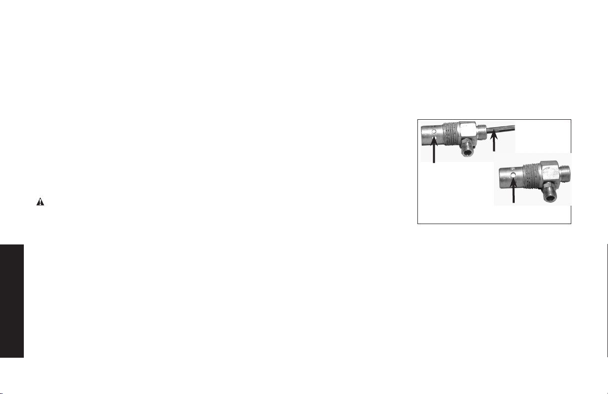
IMPORTANTE: Incluso pérdidas menores, pueden causar una
carga adicional de trabajo al compresor, dando como resultado su
rotura prematura o una desempeño inadecuada.
Tornillos del cabezal del compresor de aire. Torque
Los tornillos del cabezal del compresor de aire deben mantenerse
debidamente ajustados. Verifique el torque de los tornillos del
cabezal luego de las primeras cinco horas de operación. Reajústelos
si fuese necesario. Torsión a 18,9–21,7 Nm (14-16 ft.-lbs.).
SERVICIO Y AJUSTES
SERVICIO Y AJUSTETODO TIPO DE MANTENIMIENTO
Y REPARACIONES NO MENCIONADOS EN ESTE MANUAL,
DEBERÁN SER EFECTUADOS POR PERSONAL TÉCNICO
ESPECIALIZADO.
ADVERTENCIA: Riesgo de Operación Insegura. La unidad
arranca automáticamente cuando está enchufada. Al hacer el
mantenimiento, el operador puede quedar expuesto a fuentes
de corriente y de aire comprimido o a piezas movibles. Antes
de intentar hacer reparaciones, desconectar el compresor del
tomacorriente, drenar la presión de aire del tanque y esperar a
que el compresor se enfríe.
Para reemplazar o limpiar la válvula de
retención
1. Libere toda la presión del tanque de aire. Vea Cómo Drenar el
Español
Tanque en la sección Mantenimiento.
2. Coloque la palanca Auto/Off en la posición “Off” y desenchufe
el equipo.
3. Utilizando una llave regulable, afloje la tuerca del tubo de
salida del tanque de aire y la bomba. Retire cuidadosamente la
tubería de salida de la válvula de retención.
4. Utilizando una llave regulable, afloje la tuerca del tubo aliviador
de presión en el tanque de aire. Retire cuidadosamente la
tubería de alivio de presión de la válvula de retención.
5. Desenrosque la válvula de retención girándola hacia la
izquierda usando una llave de boca de 7/8 pulg. TOME NOTA
de la orientación para volverla a ensamblar.
6. Usando un destornillador, empuje con cuidado el disco de la
válvula hacia arriba y
hacia abajo. NOTA:
El disco de la válvula
debe moverse
libremente hacia
arriba y hacia abajo
sobre un resorte que
detiene el disco de la
válvula en la posición
cerrada. Si no lo
hace, la válvula de
retención necesita ser limpiada o reemplazada.
7. Limpie o reemplace la válvula de retención. Un solvente, tal
como un removedor de pintura o de barniz puede usarse para
limpiar la válvula de retención.
8. Aplique sellador a las roscas de la válvula de retención. Vuelva
a instalar la válvula de retención (gire a la derecha).
9. Vuelva a instalar la tubería de alivio de presión. Ajuste las
tuercas.
10. Vuelva a instalar la tubería de salida y ajuste las tuercas.
11. Ejecute el procedimiento de puesta en marcha. Vea
Procedimiento de Puesta en Marcha en la sección
Operación.
80
En posición
abierta
nada es
visible
Destornillador
En posición cerrada
el disco es visible
Page 81

Service d’entretien additionnel
Le démontage ou un entretien du compresseur d’air au-delà de
ce qui est indiqué dans ce guide ne sont pas recommandés. Si un
entretien plus poussé est requis, communiquez avec le Centre de
service sous garantie autorisé le plus proche.
ACCESORIOS
Los accesorios que se recomiendan para la herramienta están
disponibles para la compra en su distribuidor local o en el centro
de mantenimiento autorizado. Si necesita ayuda para localizar
algún accesorio para su herramienta, comuníquese llame al
1-888-895-4549 o visite nuestro sitio Web www. dewalt. com.
ADVERTENCIA: El uso de accesorios no recomendados
para utilizar con esta herramienta puede resultar peligroso. Use
solamente accesorios con una capacidad nominal igual o superior
a la de la compresor de aire.
Información del servicio técnico
Tenga a mano la siguiente información cuando llame al mantenimiento:
Número del modelo ____________ Número de serie ___________
Fecha y lugar de compra ____________________________
Reparaciones
Para garantizar la SEGURIDAD y la CONFIABILIDAD, deberán
hacerse reparaciones, mantenimiento y ajustes de esta herra-
mienta en los centros autorizados de servicio DeWALT u otras
organizaciones autorizadas. Estas organizaciones prestan servicio a las herramientas DeWALTyempleansiemprerefacciones
legitimas DeWALT.
Garantía limitada
Las herramientas de DEWALT Industrial Tools cuentan con
garantía desde la fecha de compra.
Garantía limitada de 2 AÑOS en todos los compresores con
lubricación de aceite
Garantía limitada de 1 AÑO en todos los compresores sin
aceite. Esta garantía no es transferible a los propietarios
posteriores.
DEWALT reparará o cambiará, sin cargo, a discreción de
DEWALT, cualquier defecto debido a material o mano de obra
defectuosa. Para mayores detalles sobre la cobertura de garantía
e información sobre reparaciones bajo garantía, llame al 1-(888)895 4549 o visite dewalt.com. Esta garantía no es aplicable a
accesorios o daños provocados por reparaciones realizadas o
intentadas por terceros. Esta garantía tampoco aplica a mercancía
vendida por DEWALT que ha sido fabricada por e identificada
como el producto de otra compañía, como los motores a
gasolina. En el caso, aplicará la garantía del fabricante, si existe.
CUALQUIER PÉRDIDA, DAÑO O GASTO QUE RESULTE
INCIDENTAL O INDIRECTAMENTE, O COMO CONSECUENCIA
DE ALGÚN DEFECTO, ALGUNA FALLA O AVERÍA DEL
PRODUCTO NO ESTÁ CUBIERTO POR ESTA GARANTÍA.
Algunos estados no permiten la exclusión de un límite por daños
incidentales o derivados, por lo que el límite o la exclusión anterior
puede no aplicar a su caso. LAS GARANTÍAS IMPLÍCITAS,
INCLUYENDO AQUELLAS DE COMERCIABILIDAD O
ACONDICIONAMIENTO PARA UN FIN DETERMINADO, ESTÁN
LIMITADAS A UN AÑO A CONTAR DE LA FECHA DE COMPRA
ORIGINAL. Algunos estados no permiten límites sobre el plazo
de duración de una garantía implícita, por lo que el límite anterior
puede no aplicar a su caso. Esta garantía le otorga derechos
específicos, además de los cuales puede tener otros dependiendo
del estado o provincia en que se encuentre.
Qué hará la compañía: (la compañía) cubrirá piezas y mano
de obra para corregir defectos importantes en los materiales y
81
Español
Page 82

en la fabricación durante el primer año de propiedad, con las
excepciones que se indican más adelante. Las piezas que se
utilizan en la reparación de productos completos o accesorios
están garantizadas por el resto del periodo de garantía original.
¿Qué no cubre esta garantía? Si el comprador al menudeo
original no instala, mantiene y opera dicho equipo de acuerdo con
las prácticas industriales estándar. Las modificaciones al producto
o alteraciones a los componentes, o el incumplimiento con las
recomendaciones específicas de la Compañía que se establecen
en el manual del propietario, anularán esta garantía. La Compañía
no será responsable de reparaciones, reemplazos o ajustes al
equipo, ni de costos de mano de obra realizada por el comprador
sin la aprobación previa por escrito de la Compañía. Los efectos
de la corrosión, erosión, condiciones ambientales circundantes,
defectos cosméticos y elementos de mantenimiento de rutina,
se excluyen específicamente de esta garantía. Los elementos de
mantenimiento de rutina, como aceite, lubricantes y filtros de aire,
así como los cambios de aceite, filtros de aire, tensión de bandas,
etc., son responsabilidad del propietario. Otras exclusiones
incluyen: daños durante el flete, fallas originadas por negligencia,
accidente o abuso, motores de inducción cuando es operado
desde un generador, filtraciones de aceite, fugas de aire, consumo
de aceite, acoples con fugas, mangueras, grifos, tubos de purga y
tubos de transferencia.
• Los siguientes componentes se consideran artículos de
desgaste por el uso normal y no están cubiertos después
del primer año de posesión: Correas, roldanas, volantes,
válvulas de retención, interruptores de presión,
descargadores neumáticos, controles de aceleración,
Español
motores eléctricos, escobillas, reguladores, anillos en O,
manómetros, tubos, tuberías, acoplamientos,
sujetadores, ruedas, acopladores rápidos,
empaquetaduras, sellos, carcasas de filtro de aire, anillos
de pistón, varillas de conexión y sellos de pistón.
• Los costos de mano de obra, llamadas de servicio y
viajes, no están cubiertos después del primer año de
propiedad de los compresores estacionarios
(compresores sin asas o ruedas). No están cubiertas las
reparaciones que requieren horas extraordinarias, tarifas
de fin de semana o cualquier otro costo que supere las
tarifas por mano de obra estándar del taller.
• Tiempo requerido para la capacitación de orientación
con el fin de que el centro de servicio obtenga acceso al
producto, o tiempo adicional debido a un egreso
inadecuado.
• El daño causado por voltaje incorrecto, cableado
inapropiado o el hecho de no hacer que un electricista
certificado con licencia instale el compresor, causará la
anulación e invalidación de esta garantía.
• Daño causado por un mantenimiento inadecuado del
filtro.
• Desgaste de la bomba o daño en la válvula causado por
el uso de aceite no especificado.
• Desgaste de la bomba o daño causado por cualquier
contaminación del aceite.
• Desgaste de la bomba o daño en la válvula causado por
el hecho de no seguir las directrices de mantenimiento
apropiadas.
• Utilización con un nivel de aceite por debajo del
apropiado o utilización sin aceite.
• Para motores a gas, si el producto está equipado con un
motor a gas, consulte en el manual la cobertura de
garantía del fabricante para el motor específico.
Piezas que se compran por separado: las garantías de
las piezas que se compran por separado, como bombas,
82
Page 83

motores, etc., son las siguientes:
A partir de la fecha de compra
• Todas las bombas de una y dos etapas 1 año
• Motores eléctricos 90 días
• Bomba/motor universal 30 días
• Todas las otras piezas 30 días
• No se expedirá una autorización de devolución para los
componentes eléctricos una vez que estén instalados.
¿Cómo puede obtener servicio? Con el fin de ser elegible para
el servicio bajo esta garantía debe ser el comprador original, y
proporcionar comprobante de compra de uno de los distribuidores
de la empresa, distribuidores, o las tiendas minoristas de salida.
Compresores de aire portátiles o componentes deben ser
entregados o enviados, al Centro de Servicio Autorizado más
cercano. Todos los costos de flete y los gastos asociados a viajes
deben ser pagados por el consumidor. Por favor llame a nuestro
número gratuito 1-888-895-4549 para obtener ayuda.
ESTA GARANTÍA LE OTORGA DERECHOS LEGALES
ESPECÍFICOS, Y ES POSIBLE QUE TAMBIÉN TENGA OTROS
DERECHOS QUE VARÍAN DE UN ESTADO A OTRO.
LA COMPAÑÍA NO HACE REPRESENTACIÓN O GARANTÍA
ALGUNA, YA SEA EXPRESA O IMPLÍCITA, A EXCEPCIÓN
DE LA DEL TÍTULO DE PROPIEDAD. POR LA PRESENTE,
LA COMPAÑÍA NO ASUME NINGUNA GARANTÍA IMPLÍCITA,
INCLUIDAS LAS GARANTÍAS DE COMERCIABILIDAD Y DE
IDONEIDAD PARA UN PROPÓSITO ESPECÍFICO. SE EXCLUYE
TODA RESPONSABILIDAD POR DAÑOS Y PERJUICIOS
EMERGENTES O INCIDENTALES EN VIRTUD DE CUALQUIER
OTRA GARANTÍA, OTROS CONTRATOS, NEGLIGENCIA U
OTROS ACTOS DE AGRAVIO EN LA MEDIDA EN QUE LA LEY LO
PERMITA.
REEMPLAZO GRATUITO DE LAS ETIQUETAS DE
ADVERTENCIA: Si sus etiquetas de advertencia se tornan
ilegiblesofaltan,llameal1-888-895-4549paraquesele
reemplacen gratuitamente.
Español
83
Page 84

Guía de detección de problemas
Esta sección proporciona una lista de las fallas que se presentan con mayor frecuencia, sus causas y las medidas correctivas correspondientes. El operador o el personal de mantenimiento pueden llevar a cabo algunas de estas acciones correctivas, pero es posible que otras
necesiten la asistencia de un técnico DeWALT calificado o de su distribuidor.
Problema Código
Pérdidas de aire ........................................................................................................................ 1
Pérdidas de aire en el tanque de aire o en las soldaduras del tanque de aire ..............................2
Pérdidas de aire entre el cabezal y la placa de la válvula ..............................................................3
Pérdidas de aire de la válvula de seguridad ................................................................................. 4
El compresor no suministra suficiente aire para operar los accesorios ................................... 1, 5, 6, 7, 9, 10
Entrada restringida de aire.. ...................................................................................................... 9
Aceite en el aire de descarga .................................................................................................... 9, 19, 31
Ruido de golpeteo .......................................................................................................................4, 10, 11, 12, 13, 14
Desgaste excesivo de la correa ................................................................................................ 10, 11, 14, 15
Sonidos agudos ......................................................................................................................... 10
Humedad en la carcaza de la bomba ....................................................................................... 1, 3, 8, 17, 18, 19, 20, 21, 22
Consumo excesivo de corriente ................................................................................................14, 26, 27
El compresor no arranca en temperaturas frías ........................................................................ 17, 34, 35
La lectura de la presión en el manómetro regulado cae cuando se usa un accesorio ................... 23
La perilla del regulador tiene una pérdida constante de aire ......................................................... 24
El regulador no cierra la salida de aire ...................................................................................... 24
No se acumula presión en el tanque de aire.............................................................................25
Español
Se detiene el compresor ...........................................................................................................28, 29, 30
Sobrecalentamiento ................................................................................................................... 27, 32, 33
84
Page 85

Códigos de detección de problemas
CÓDIGO CAUSA POSIBLE SOLUCIÓN POSIBLE
1
2
3
4
5
6
7
8
9
10
11
12
13
14
Las conexiones no están ajustadas
Tanque de aire defectuoso. Se debe reemplazar el tanque de aire. No repare la pérdida.
Sellos de pérdidas Comuníquese con un centro de servicio de fábrica DeWALT o con un
Válvula de seguridad defectuosa Opere la válvula de seguridad manualmente tirando del anillo. Si la vál-
Uso excesivo y prolongado de aire Disminuya el uso de aire.
El compresor no es lo sucientemente grande para el ac-
cesorio
Agujero en la manguera de aire Controle y reemplace la manguera de aire de ser necesario.
La unidad funciona en lugares húmedos o mojados Traslade la unidad a un área seca y bien ventilada
Filtro de entrada de aire restringido Limpie o reemplace el ltro de entrada de aire
Correa oja Controle la tensión de la correa, consulte Ajustar la tensión de la correa
Polea suelta Ajuste el tornillo de jación de la polea, aplique una torsión entre
Volante suelto Ajuste el tornillo del volante, aplique una torsión entre
Acumulación de carbono en la bomba Comuníquese con un centro de servicio de fábrica DeWALT o con un
Ajustar la correa Controle la tensión de la correa, consulte Ajustar la tensión de la correa
Ajuste las conexiones en los lugares donde sienta escapes de aire. Controle las conexiones con una solución de agua jabonosa. NO AJUSTE
DEMASIADO.
ADVERTENCIA: Riesgo de explosión. No perfore, suelde ni modifique
el tanque de aire o el mismo se debilitará. El tanque de aire se puede
romper o explotar.
centro de servicio autorizado DeWA LT.
vula aún pierde, debe ser reemplazada.
Controle los requisitos de aire del accesorio. Si es mayor que el ujo de
aire o la presión provista por su compresor de aire, necesita un compresor más grande para operar el accesorio.
en la sección Mantenimiento.
16,4– 20,3 Nm (145 y 180 libras-pulgadas)
(
15 y 18 libras-pie).
centro de servicio autorizado DeWA LT.
en la sección Mantenimiento.
Español
.
20,3 a 24,4 Nm
85
Page 86

CÓDIGO CAUSA POSIBLE SOLUCIÓN POSIBLE
Mala alineación de la polea Consulte Alineación de la polea y el volante en la sección
15
Mantenimiento.
El nivel de aceite de la bomba es bajo Agregue a la bomba una mezcla sintética de aceite para compresores
16
de aire sin detergente. Consulte Aceite de la bomba del compresor en
la sección Mantenimiento.
Aceite tipo detergente utilizado en la bomba Drene el aceite y vuelva a llenar la bomba con una mezcla sintética de
17
aceite para compresores de aire sin detergente.
Ciclos de trabajo extremadamente livianos. Haga funcionar la unidad en ciclos de trabajo más largos. Se recomienda
18
hacerla funcionar a alta velocidad entre el 50 y el 75% del tiempo de
funcionamiento y operarla en marcha en espera el 25% del tiempo de
funcionamiento
Anillos de pistón dañados o gastados Comuníquese con un centro de servicio de fábrica DeWALT o con un
19
centro de servicio autorizado DeWA LT.
Cilindro o pistón dañados o gastados Comuníquese con un centro de servicio de fábrica DeWALT o con un
20
centro de servicio autorizado DeWA LT.
Terminación del cilindro del compresor gastada Comuníquese con un centro de servicio de fábrica DeWALT o con un
21
centro de servicio autorizado DeWA LT.
Agua en el aceite de la bomba Drene el aceite y vuelva a llenar la bomba con una mezcla sintética de
22
aceite para compresores de aire sin detergente.
23
El regulador no está correctamente ajustado para el
uso de un accesorio
Es normal que se presente alguna caída de presión cuando
se usa un accesorio, ajuste el regulador como se indica en
Regulador en la sección Características si la caída es excesiva.
NOTA: Ajuste la presión regulada bajo condiciones de flujo
mientras se usa el accesorio.
24
25
Español
El regulador está dañado Reemplácelo
Regulador abierto Gire la perilla del regulador en sentido contrario a las agujas del reloj
hasta su tope incorporado y empuje la perilla hacia adentro para bloquearla.
86
Page 87

CÓDIGO CAUSA POSIBLE SOLUCIÓN POSIBLE
26
Volaje bajo/sobrecarga del motor CVerifique que el suministro de energía sea el adecuado y que
el compresor se encuentre conectado en un circuito exclusivo.
Si está usando un cordón prolongador, intente utilizar el equipo
sin el mismo. Si el compresor de aire se conecta a un circuito
protegido por un fusible, utilice fusibles temporizados de doble
elemento (sólo Buss Fusetron tipo “T”).
27
Pasajes de aire restringidos Inspeccione y reemplace los tubos de transferencia o la
válvuladeretención,segúnseanecesario.
28
29
30
Bajo voltaje al motor Suministre la energía adecuada.
Válvula de retención dañada. Reemplace la válvula de retención.
Bomba tomada
ComuníqueseconuncentrodeserviciodefábricaDeWALToconun
centro de servicio autorizado DeWA LT.
31
Nivel de aceite demasiado alto Reduzca hasta el nivel adecuado. See Compressor Pump Oil
under Maintenance.
32
Mala ventilación Vuelva a ubicar el compresor en una zona con aire fresco, seco
y bien circulado, por lo menos a 30 cm (12”) de la pared más
cercana.
33
34
35
Superficies de enfriamiento sucias Limpie muy bien todas las superficies de enfriamiento.
Demasiada contrapresión en el tanque Abra la llave de desconpresión al arrancar el motor.
El compresor está demasiado frío Mueva el compresor a un lugar más cálido.
Español
87
Page 88
GLOSARIO
CFM: Pies cúbicos por minuto.
SCFM: pies cúbicos estándarpor minuto; unidadde medida de
suministro de aire.
PSI: Libras por pulgada cuadrada; una unidad de medida de
presión.
Presión de arranque:Mientras elmotorestáapagado, la presión
del tanque de aire cae cuando utiliza un accesorio. Cuando la
presión del tanque baja a determinado nivel el motor volverá a
encenderse automáticamente.Lapresiónbajaenlacualelmotor
se vuelve a encender automáticamente se llama presión de
arranque.
Presión de corte: Cuando se enciende o cuando comienza a
funcionar un compresor de aire, comienza a elevarse la presión
del aire en el tanque de aire. Se eleva hasta determinada presión
antesdequeelmotorseapagueautomáticamente,protegiendoa
sutanquedeairedeunapresióndeairemayorasucapacidad.La
presión alta en la cual el motor se apaga se llama presión de corte.
Bien ventilado: Un medio de proveer aire fresco para contrarrestar
el escape de gases o los vapores peligrosos.
Circuito dedicado: Un circuito eléctrico reservado para uso
exclusivo del compresor de aire.
ASME: American Society of Industrial Engineers.
Indica que los componentes se fabricaron, probaron y examinaron
de acuerdo con las especificaciones establecidas por ASME
CSA:Laasociacióncanadiensedelosestándares
Español
Indica que los productos que hacen esta marca haber
sido fabricados, haber sido probados y haber examinado
alosestándaresquesonfijadosporCSA.
La asociación canadiense de los estándares (los E.E.U.U.)
Indica que los productos que hacen esta marca haber
fabricado, probado y examinado a los estándares que
son fijados por CSA. Estos productos también se
conformanconelestándar1450deU.L..
Código de California: la unidad puede cumplir con las secciones
(I)(2)/(M)(2)delCódigo462deCalifornia.Laetiquetadeespecificaciones/modelo se encuentra en el costado del tanque de aire
en las unidades que cumplen con el Código de California.
88
Page 89

NOTES
Page 90

NOTES
Page 91

NOTES
Page 92

For product, service or warranty information contact us at:
Para el producto, servicio o información sobre la garantía contacte con nosotros en:
Pour les produits, services ou informations sur la garantie nous contracter à:
1-888-895-4549
www.dewalt.com
MAT Industries, LLC, Long Grove, IL 60047
Under license from DEWALT Industrial Tool Co.
Bojo licencia de DEWALT Industrial Tool Co.
Sous licence de DEWALT Industrial Tool Co.
The following are trademarks for one or more DEWALT power tools: thee yellow and black color scheme; the “D” shaped air intake grill; the array of pyramids on the handgrip;
the kit box configuration; and the array of lozenge shape humps on the surface of the tool.
Las siguientes son características únicas de una o más herramientas eléctricas y accesorios de DEWALT: El esquema de color amarillo y negro, la parrilla de admisión de aire
en “D”, la formación de pirámides en el mango, la configuración de la caja de herramientas y la formación de rombos en la superficie de la herramienta.
Vous trouverez ci-après les marques de commerce d’un ou plusieurs outils électriques et accessoires DEWALT. L’agencement de couleurs jaune et noir, la grille d’admission
d’air en forme de “D”, la distribution de pyramides sur la poignée, le format du boîter et la matrice complexe de bosses en forme de losanges sur la surface de l’outil.
 Loading...