

Page 1

DXCMH1393075
Two Stage, Belt Drive, Gasoline Driven Air Compressors
Les compresseurs d'air à deux étages, la courroie d'entraînement, entraîné par un moteur essence
Compresores motor de gasolina impulsado de aire, dos etapa y accionamiento por correa
INSTRUCTION MANUAL
GUIDE D'UTILISATION
MANUAL DE INSTRUCCIONES
INSTRUCTIVO DE OPERACIÓN, CENTROS DE SERVICIO Y
PÓLIZA DE GARANTÍA. ADVERNTENCIA: LÉASE ESTE
INSTRUCTIVO ANTES DE USAR EL PRODUCTO.
If you have questions or comments, contact us.
Pour toute question ou tout commentaire, nous contacter.
Si tiene dudas o comentarios, contáctenos.
1-888-895-4549 • www.DEWALT.com
MAT Industries, LLC, Long Grove, IL 60047
(OCT2015) Part No. 200-3003-B DXCMH1393075 Copyright © 2014, 2015 DEWALT
Page 2
2
English
FIG. 1
A
I
J
G
D
E
H
F
N
M
L
K
B
C
O
Pump Specications
2 Cylinder
Two Stage
Oil Lubricated
Cast iron crankcase, cylinder, and head
Weight: 136 lbs. (62 kg.)
Oil Capacity: 53 oz. (1567 mL)
Engine Specications
Honda 389 cc
Internal Combustion
4-stroke
High RPM 3600
Specications
MODEL DXCMH1393075
WEIGHT
497 lbs. (225,4 kg)
HEIGHT
46.4” (1178.6 mm)
WIDTH
19.5” (495.3 mm)
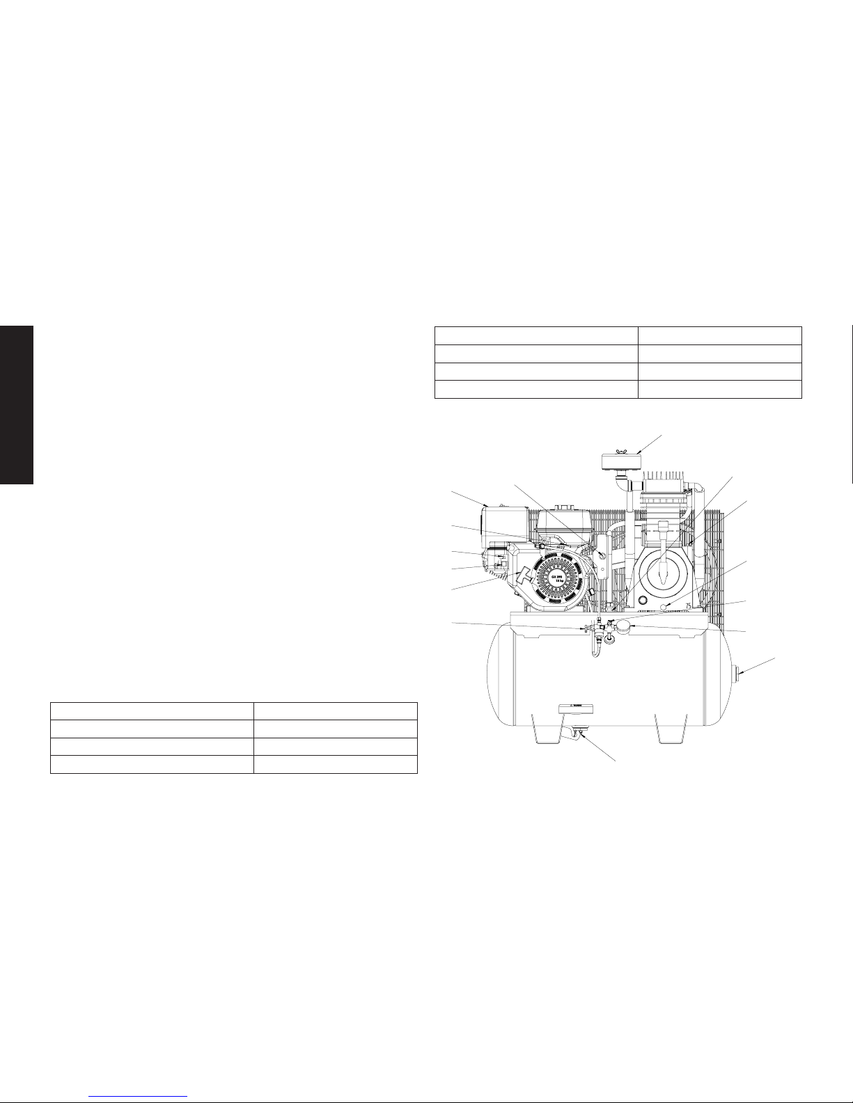
Air Compressor
A. Pump Air Intake Filter
B. Engine Air Filter
C. Engine START/RUN/OFF
Switch
D. Air Tank Pressure Gauge
E. Air Outlet
F. Unloader Valve
G. Safety Vavle
H. Air Tank Drain Valve
I. Pump Oil Fill Plug
J. Pump Oil Drain Plug
K. Fixed Throttle
L. Choke Control
M. Fuel Valve Lever
N. Starter Grip
O. Check Valve
MODEL DXCMH1393075
LENGTH
42" (1066.8 mm)
AIR TANK CAPACITY
30 gallons (113,6 liters)
APPROX. BLOW OFF PRESSURE
175 psi
Page 3
3
English
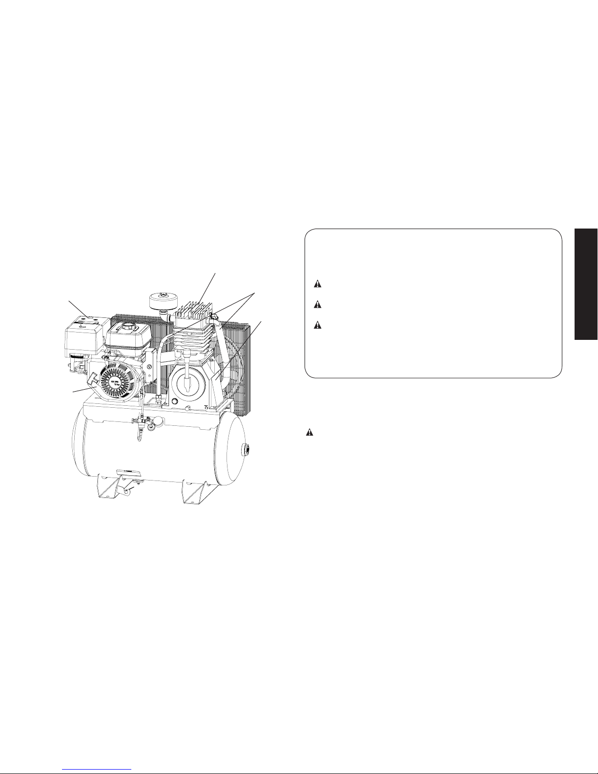
Hot Surfaces
FIG. 2
Denitions: Safety Guidelines
The definitions below describe the level of severity
for each signal word. Please read the manual and pay attention to these symbols.
DANGER: Indicates an imminently hazardous situation
which, if not avoided, will result in death or serious injury.
WARNING: Indicates a potentially hazardous situation
which, if not avoided, could result in death or serious injury.
CAUTION: Indicates a potentially hazardous situation
which, if not avoided, may result in minor or moderate
injury.
NOTICE: Indicates a practice not related to personal injury
which, if not avoided, may result in property damage.
IF YOU HAVE ANY QUESTIONS OR COMMENTS ABOUT
THIS OR ANY DeWALT TOOL, CALL US TOLL FREE AT:
1-888-895-4549
Important Safety Instructions
DANGER: Carbon Monoxide. Using an engine indoors can
kill you in minutes. Engine exhaust contains high levels of
carbon monoxide (CO), a poisonous gas you cannot see or
smell. You may be breathing CO even if you DO NOT smell
engine exhaust.
• NEVER use an engine inside homes, garages, crawlspaces,
or other partly enclosed areas. Deadly levels of carbon monoxide can build up in these areas. Using a fan or opening
windows and doors does NOT supply enough fresh air.
• ONLY use outdoors and far away from open windows, doors
and vents. These openings can pull in engine exhaust.
OUTLET TUBES
COMPRESSOR CYLINDER
& HEAD
PUMP
CRANKCASE
ENGINE MUFFLER
GASOLINE
ENGINE
Page 4

4
English
SAVETHESEINSTRUCTIONS
DANGER: RISK OF EXPLOSION OR FIRE
WHAT CAN HAPPEN HOW TO PREVENT IT
• Spilled gas o line and it’s
vapors can be come ignited
from cigarette sparks, electrical arcing, exhaust gas es and
hot engine components such
as the muffler.
• Shut off en gine and allow it to
cool before adding fuel to the
tank.
• Use care in fill ing tank to avoid
spill ing fuel. Move unit away
from fueling area before starting en gine.
• Heat will ex pand fuel in the
tank which could result in
spillage and pos si ble fire
explosion.
• Keep maximum fuel level
1/2" (12.7 mm) be low
bottom of filler neck
to allow for expansion.
• Even when the engine is used correctly, CO may leak into
your home. ALWAYS use a battery-powered or battery
backup CO alarm (not supplied) in the home. Read and fol-
low all directions for CO alarm before using. If you start to
feel sick, dizzy or weak at anytime, move to fresh air immediately. See a doctor. You could have carbon monoxide
poisoning.
WARNING: Do not operate this unit until you read this
instruction manual and the engine instruction manual for safety,
operation and maintenance instructions.
WARNING: This product may not be equipped with a sparkarresting muffler. If the product is not equipped and will be used
around flam ma ble ma teri als or on land covered with materials such
as agricultural crops, forest, brush, grass or other similar items,
then an ap proved spark arrester must be installed and is legally
required in the state of California. It is a violation of California statutes
section 130050 and/or sec tions 4442 and 4443 of the California
Public Re sourc es Code, unless the engine is equipped with a spark
arrester, as defined in section 4442, and maintained in ef fec tive
work ing order. Spark arresters are also required on some U.S.
For est Service land and may also be legally required under other
statutes and or di nanc es.
WARNING: This product contains chemicals known to the
State of California to cause cancer, and birth defects or other
reproductive harm. Wash hands after handling.
WARNING: Some dust contains chemicals known to the State
of California to cause cancer, birth defects or other reproductive
harm such as asbestos and lead in lead based paint.
WARNING: The engine exhaust from this product contains
chemicals known to the State of California to cause cancer, birth
defects or other reproductive harm.
Page 5

5
English
• Combustiblematerials
whichcomeintocontact
withhotenginepartscan
becomeignited.
• Add fuel outdoors in a well
ventilated area. Make sure
there are no sources of ignition, such as cigarettes near
refueling location.
• Operate compressor in a
clean, dry, well ventilated area
a minimum of 48" (1.22 m)
from any building, object
or wall. Do not operate unit
indoors or in any confined
area.
• Operate compressor in an
open area away from dry
brush, weeds or other combustible materials.
• Improperly stored fuel could
lead to acciden tal ignition.
Fuel im prop er ly secured
could get into the hands of
children or oth er un qual i fied
persons.
• Store fuel in an OSHA-approved con tain er, in a se cure
location away from work area.
• Unattendedoperationof
thisproductcouldresultin
personalinjuryorproperty
damage.Toreducethe
riskoffire,donotallow
thecompressortooperate
unattended.
• Always remain in attendance
with the product when it is
operating.
DANGER: RISK TO BREATHING (ASPHYXIATION)
WHAT CAN HAPPEN HOW TO PREVENT IT
• Breathing ex haust fumes
will cause se ri ous injury
or death! En gine exhaust
con tains carbon mon ox ide,
an odorless and deadly gas.
• Always operate air compressor
outside in a clean, well
ventilated area. Avoid enclosed
areas such as garages,
basements, storage sheds,
which lack a steady exchange
or air. Keep children, pets
and others away from area of
operation.
• The compressed air directly
from your compressor is not
safe for breathing. The air
stream may contain carbon
monoxide, toxic vapors,
or solid particles from the
air tank. Breathing these
contaminants can cause
serious injury or death.
• Never use air obtained directly
from the compressor to supply
air for human consumption.
The compressor is not
equipped with suitable filters
and in-line safety equipment
for human consumption.
Page 6

6
English
• Exposure to chemicals
in dust created by
power sanding, sawing,
grinding, drilling and other
construction activities may
be harmful.
• Sprayed materials such as
paint, paint solvents, paint
remover, insecticides, weed
killers, may contain harmful
vapors and poisons.
• Work in an area with good
cross ventilation. Read and
follow the safety instructions
provided on the label or
safety data sheets for the
materials you are spraying.
Always use certified safety
equipment: NIOSH/OSHA
respiratory protection or
properly fit ting face mask
designed for use with your
specific application.
DANGER: RISK OF BURSTING
Air Tank: On February 26, 2002, the U.S. Consumer Product Safety
Commission published Release # 02-108 concerning air compressor tank safety:
Air compressor receiver tanks do not have an infinite life. Tank life is
dependent upon several factors, some of which include operating
conditions, ambient conditions, proper installations, field modifications, and the level of maintenance. The exact effect of these factors on air receiver life is difficult to predict.
If proper maintenance procedures are not followed, internal corrosion to the inner wall of the air receiver tank can cause the air tank
to unexpectedly rupture allowing pressurized air to suddenly and
forcefully escape, posing risk of injury to consumers.
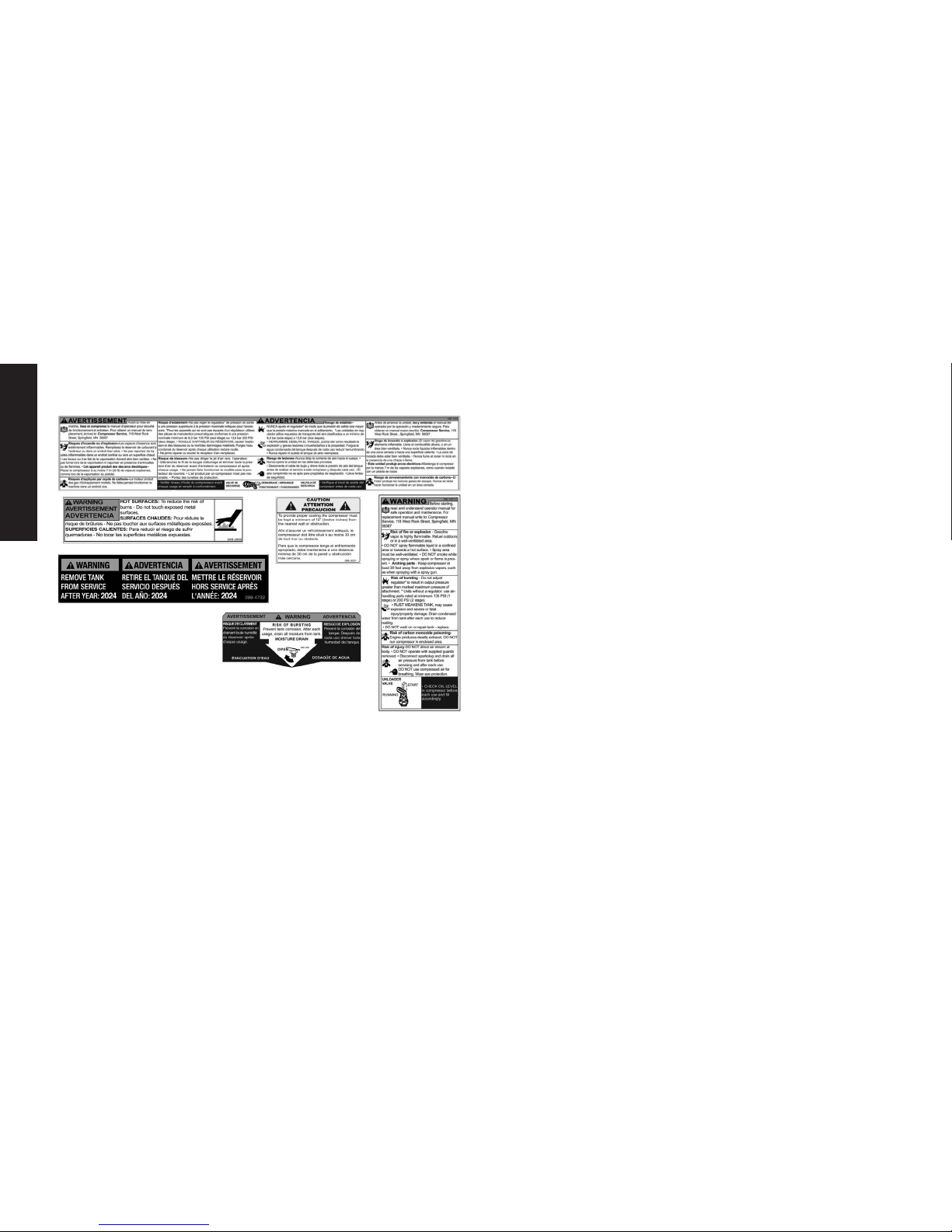
Your compressor air tank must be removed from service by the end
of the year shown on your tank warning label.
The following conditions could lead to a weakening of the air tank,
and result in a violent air tank explosion:
WHAT CAN HAPPEN HOW TO PREVENT IT
• Failure to properly drain
condensed water from air
tank, causing rust and thinning
of the steel air tank.
• Drain air tank daily or after each
use. If air tank develops a leak,
replace it immediately with
a new air tank or replace the
entire compressor.
• Modifications or attempted
repairs to the air tank.
• Never drill into, weld or make
any modifications to the air
tank or its attachments. Never
attempt to repair a damaged or
leaking air tank. Replace with a
new air tank.
• Unauthorized modifications
to the unloader valve,
safety valve, or any other
components which control air
tank pressure.
• The air tank is designed
to withstand specific
operating pressures. Never
make adjustments or parts
substitutions to alter the factory
set operating pressures.
• Excessive vibration can
weaken the air tank and
cause rupture or explosion.
Excessive vibration will occur if
the compressor is not properly
mounted or if engine operates
above recommended RPM.
• Do not remove the stiffener bar
connecting the compressor
pump to the engine, except
to adjust belt tension. Then
securely tighten the stiffener
bar bolts. This bar controls unit
vibration.
Page 7

7
English
Attachments&Accessories:
• Exceeding the pressure rating
of air tools, spray guns, air
operated accessories, tires
and other inflatables can
cause them to explode or
fly apart, and could result in
serious injury.
• Follow the equipment
manufacturers
recommendation and never
exceed the maximum allowable
pressure rating of attachments.
Never use compressor to
inflate small low pressure
objects such as children’s toys,
footballs, basketballs, etc.
Tires:
• Over inflation of tires could
result in serious injury and
property damage.
• Use a tire pressure gauge to
check the tires pressure before
each use and while inflating
tires; see the tire sidewall for
the correct tire pressure.
NOTE: Air tanks, compressors
and similar equipment used to
inflate tires can fill small tires
very rapidly. Adjust pressure
regulator on air supply to no
more than the rating of the
tire pressure. Add air in small
increments and frequently use
the tire gauge to prevent over
inflation.
DANGER: RISK OF INJURY OR PROP ER TY DAMAGE WHEN
TRANSPORTING OR STORING
WHAT CAN HAPPEN HOW TO PREVENT IT
• Oil can leak or spill and could
result in fire or breathing
hazard; serious injury or
death can result. Oil leaks will
damage carpet, paint or other
surfaces in vehicles or trailers.
• Always place compressor
on a protective mat when
transporting to protect against
damage to vehicle from leaks.
Remove compressor from
vehicle immediately upon
arrival at your destination.
Always keep compressor level
and never lie on its side.
Page 8

8
English
WARNING: RISKFROMMOVINGPARTS
WHAT CAN HAPPEN HOW TO PREVENT IT
• The engine can start
accidentally if the flywheel is
turned by hand or moved by
pulling on the starter rope.
• Always disconnect the spark
plug and bleed pressure from
the air tank before performing
maintenance.
• Moving parts such as the
pulley, flywheel, and belt can
cause serious injury if they
come into contact with you or
your clothing.
• Never operate the compressor
with guards or covers which are
damaged or removed.
• Keep your hair, clothing and
gloves away from moving parts.
Loose clothes, jewelry or long
hair can be caught in moving
parts.
• Air vents may cover moving
parts and should be avoided as
well.
• Attempting to operate
compressor with damaged or
missing parts or attempting
to repair compressor with
protective shrouds removed
can expose you to moving
parts and can result in serious
injury.
• Any repairs required on this
product should be performed
by a DeWALT factory service
center or a DeWALT authorized
service center.
WARNING: RISK FROM FLYING OBJECTS
WHAT CAN HAPPEN HOW TO PREVENT IT
• The compressed air stream
can cause soft tissue damage
to exposed skin and can
propel dirt, chips, loose
particles and small objects
at high speed, resulting in
property damage or personal
injury.
• Always wear certified safety
equipment: ANSI Z87.1 eye
protection (CAN/CSA Z94.3)
with side shields when using
the compressor.
• Never point any nozzle or
sprayer toward any part of
the body or at other people or
animals.
• Always turn the compressor
off and bleed pressure from
the air hose and air tank before
attempting maintenance,
attaching tools or accessories.
Page 9

9
English
WARNING: RISK OF HOT SURFACES
WHAT CAN HAPPEN HOW TO PREVENT IT
• Touching exposed metal
such as the compressor head,
engine head, engine exhaust
or outlet tubes, can result in
serious burns.
• Never touch any exposed
metal parts on compressor
during or immediately after
operation. Compressor will
remain hot for several minutes
after operation
• Do not reach around
protective shrouds or attempt
maintenance until unit has
been allowed to cool.
WARNING: RISK OF UNSAFE OPERATION
WHAT CAN HAPPEN HOW TO PREVENT IT
• Unsafe op er a tion of your air
compressor could lead to se rious in ju ry or death to you or
others.
• Review and understand all
instructions and warnings in
this manual.
• Be come fa mil iar with the op era tion and con trols of the air
compressor.
• Keep operating area clear of all
persons, pets, and obstacles.
• Keep chil dren away from the air
compressor at all times.
• Do not operate the product
when fatigued or under the
influence of alcohol or drugs.
Stay alert at all times.
• Never defeat the safety fea tures
of this prod uct.
• Equip area of operation with a
fire extinguisher.
• Do not op er ate machine with
missing, broken, or un au thorized parts.
• Never stand on the
compressor.
Page 10
10
English
CAUTION: RISK FROM NOISE
WHAT CAN HAPPEN HOW TO PREVENT IT
• Under some conditions and
duration of use, noise from
this product may contribute to
hearing loss.
• Always wear certified safety
equipment: ANSI S12.6
(S3.19) hearing protection.
SAVETHESEINSTRUCTIONSFORFUTURE
USE
Know Your Air Compressor
READ THIS OWNER’S MANUAL AND SAFETY RULES BEFORE
OPERATING YOUR UNIT. Compare the illustrations with your
unit to familiarize yourself with the location of various controls
and adjustments. Save this manual for future reference.
FEATURES
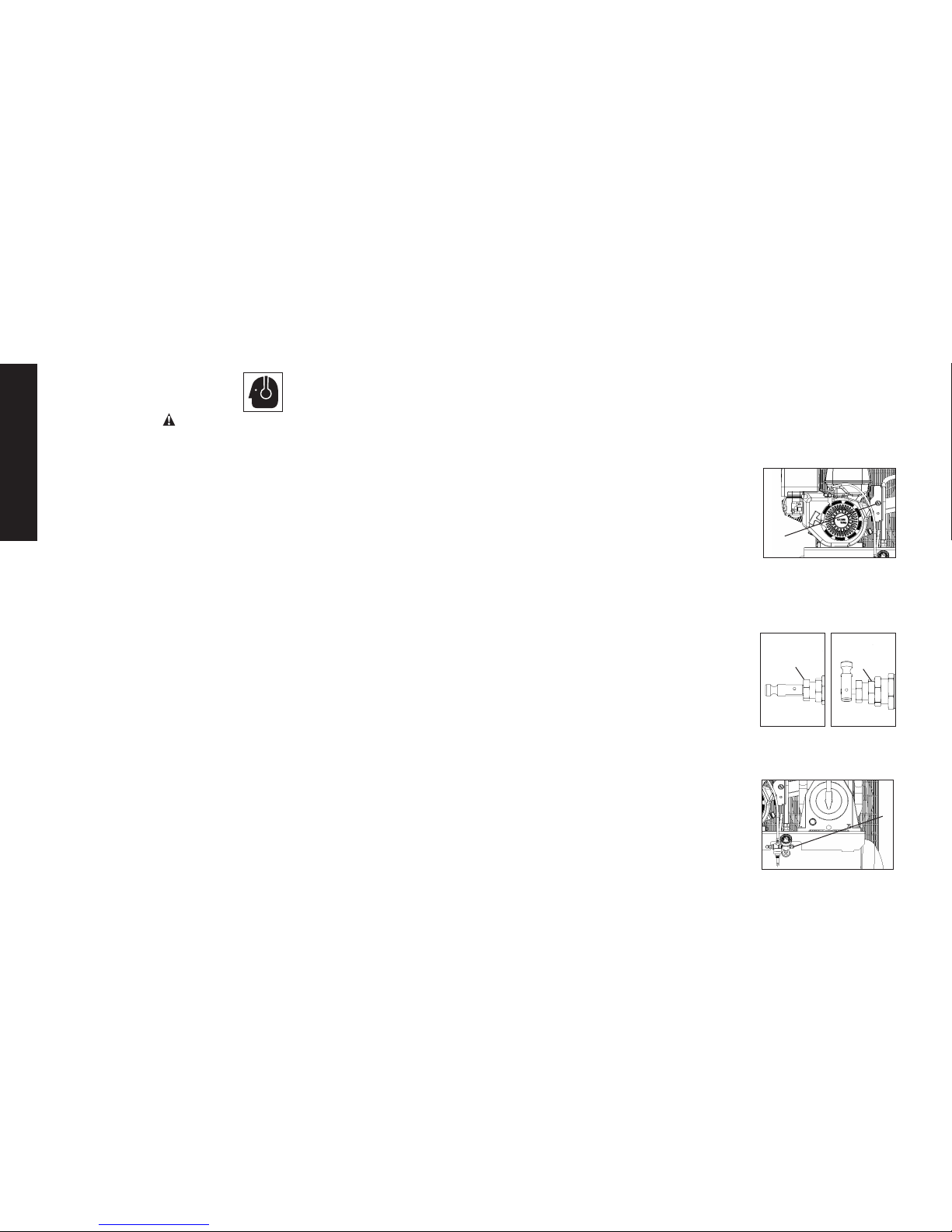
ELECTRIC START
The engine switch (C) can be placed in three
C
positions; START, RUN and OFF. See Starting
under Operation for complete starting
instructions.
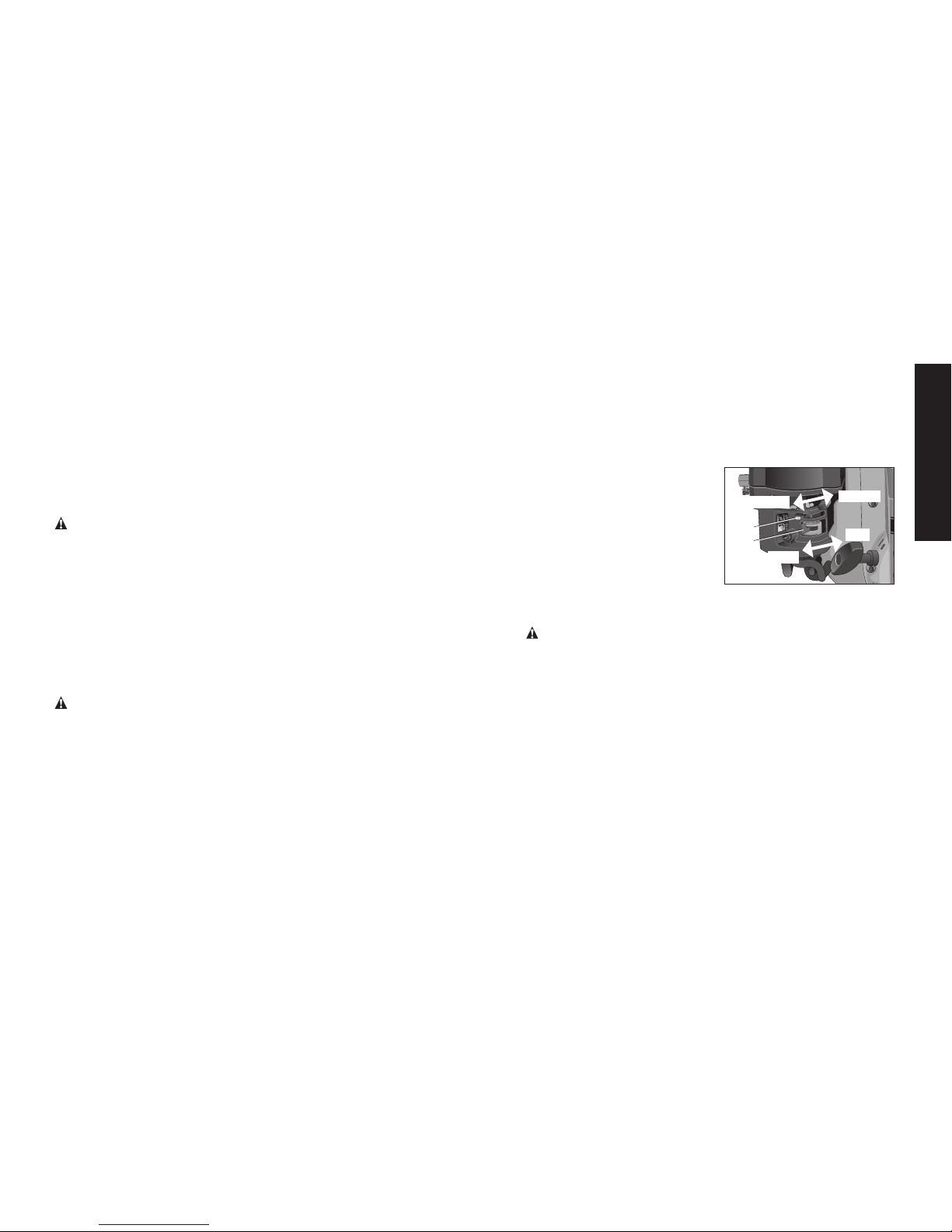
UNLOADER VALVE
When the maximum air tank pressure is obtained, the unloader
valve (F) will blow-off. This will cause the compressor to exhaust
the air to the atmosphere and not the tank.
ManualLock:The manual lock allows you to
OPEN
F
CLOSED
F
manually unload the compressor with air
pressure in the air tank. To operate the manual
lock:
Rotate the manual lock unloader lever to the
open position to prevent air tank pressure
buildup. Rotate manual lock unloader lever to
the closedposition after starting the engine to allow air tank pressure
to build. NOTE: Air will not build in tank when manual lock unloader
lever in the open position.
SAFETY VALVE
This valve (G) is designed to prevent system
G
failures by relieving pressure from the system
when the compressed air reaches a predeter-
Page 11

11
English
mined level. The valve is preset by the manu facturer and must not be
removed or modified in any way.
CHECK VALVE
When the air compressor is operating, the
O
check valve (O) is open, allowing compressed
air to enter the air tank. When the air
compressor reaches cut-out pressure, the
check valve closes, allowing air pressure to
remain inside the air tank.
AIR INTAKE FILTER
The filter (A) is designed to clean air entering the
A
pump. To ensure the pump continually receives a
clean, cool, and dry air supply the filter must always
be clean and the filter intake must be free from
obstructions.
AIR TANK DRAIN VALVE
The drain valve (H) is located at the base of
H
the air tank and is used to drain
condensation at the end of each use. See
Draining Air Tank under Maintenance.
TANK PRESSURE GAUGE
The tank pressure gauge (D) indicates the
D
reserve air pressure in the tank.
GLOBE VALVE/AIR DISCHARGE VALVE:
(sold separately, not shown)
Opens and closes air distribution from compressor.
REGULATOR (sold separately, not shown):
An air pressure regulator or a separate air transformer which
combines the functions of air regulation and/or moisture and dirt
removal is recommended for most applications.
AIR COMPRESSOR PUMP
The pump compresses air into the air tank. Working air is not available
until the compressor has raised the air tank pressure above that
required at the air outlet.
GASOLINE ENGINE
The gasoline engine powers the pump. The engine drives a pulley
and belt, which transfers power from the engine to the pump
pistons via a flywheel and a crankshaft. The flywheel fan helps cool
the pump.
THROTTLE CONTROL
When maxi mum air tank pres sure is reached and the unloader valve
vents air, it activates the throttle control on the engine. This gas
saving feature holds the engine at a factory-set idling speed until air
pressure in the air tank drops to reset pressure. The unloader valve
then reactivates the throttle control and accelerates the engine to
full throttle.
LOW OIL SHUT DOWN SENSOR
The air compressor engine is equipped with a low oil shutdown
sensor. This is a safety device designed to protect your engine
from damage in the event the oil level in the crankcase is below
minimum.
If the oil in the engine gets low while the air compressor is running it
will automatically shut down the engine and will not restart until oil
is added to the engine. If the oil is low before start-up, the engine
will not start until oil is added.
NOTE: The low oil shutdown sensor is very sensitive. You must fill
the engine to the full mark on the dipstick to inactivate this safety
device.
Page 12

12
English
INSTALLATION
Assembly(refer to Fig. 1, pg. 2)
Unpack the air compressor. Inspect the unit for damage. If the
unit has been damaged in transit, contact the carrier and
complete a damage claim. Do this immediately because there are
time limitations to damage claims.
The carton should contain:
• air compressor
• operator and parts manuals
• engine manual
• vibration pads (4)
Check the compressor’s serial label to ensure that you have
received the model ordered, and that it has the required pressure
rating for its intended use.
INSTALLING HOSES
WARNING: Risk of unsafe operation. Firmly grasp hose in hand
when installing or disconnecting to prevent hose whip.
1. Pull ring on safety valve allowing air to bleed from the tank until
tank pressure is 0 psi. Release safety valve ring.
2. Apply sealant tape to hose threads.
3. Assemble hose to air outlet (E). IMPORTANT: Do not assemble
splitters directly to the air outlet (E).
NOTE: Assembling quick connect bodies to air outlet and quick
connect plugs to hose ends make connecting and disconnecting
hoses simple and easy. Quick connect bodies and plugs are
available for purchase from your local dealer or authorized service
center.
DISCONNECTING HOSES
WARNING: Risk of unsafe operation. Firmly grasp hose in hand
when installing or disconnecting to prevent hose whip.
1. Pull ring on safety valve allowing air to bleed from the tank until
tank pressure is 0 psi. Release safety valve ring.
2. Remove hose from air outlet (E).
Lubrication and Oil
ENGINE
1. The engine was filled WITH oil at the manufacturer. Check
engine oil level before operating unit. If necessary, fill engine
to the appropriate level with recommended oil, see engine's
instruction manual supplied by engine manufacturer for correct
procedure.
2. Add fuel to engine. See engine's instruction manual supplied by
engine manufacturer for correct procedure.
WARNING: Risk of explosion or fire. Gasoline vapor is highly
flammable. Refuel outdoors preferably, or only in well-ventilated
areas. Do not refuel or check gasoline level while the engine is
running. Do not store, spill or use gasoline near an open flame, a
source of sparks (such as welding), or near operating electrical
equipment.
AIR COMPRESSOR
The air compressor pump was filled WITH oil at the manufacturer.
Check air compressor pump oil level before operating unit. See
Compressor Pump Oil under Maintenance.
Compatibility
Air tools and accessories that are run off the compressor must be
compatible with petroleum based products. If you suspect that a
material is not compatible with petroleum products, an air line filter
for removal of moisture and oil vapor in compressed air is required.
NOTE: Always use an air line filter to remove moisture and oil vapor
Page 13
13
English
when spraying paint.
Location
WARNING: Risk of breathing. Exhaust from the gasoline engine
contains deadly carbon monoxide, which is odorless and toxic.
Operate engine only in well ventilated areas.
NOTICE: Risk of property damage. In order to avoid damaging
the air compressor, do not allow the unit to be tilted more than
10º when operating.
Place air compressor at least 4 ft (1.2 m) away from obstacles that
may prevent proper ventilation. Keep unit away from areas that
have dirt, vapor and volatile fumes in the atmosphere which may
clog and gum up the intake filter and valves, causing inefficient
operation.
HUMID AREAS
In frequently humid areas, moisture may form in the pump and
produce sludge in the oil, causing running parts to wear out
prematurely. Excessive moisture is especially likely to occur if
the unit is located in an unheated area that is subject to large
temperature changes. Two signs of excessive humidity are external
condensation on the pump when it cools down and a “milky”
appearance in compressor oil. You may be able to prevent
moisture from forming in the pump by increasing ventilation or
operating for longer intervals.
NOISE CONSIDERATIONS
Consult local officials for information regarding acceptable noise
levels in your area. To reduce excessive noise, use vibration mounts
or silencers, relocate the unit or construct total enclosures or baffle
walls. Contact a DeWALT service center or call 1-888-895-4549 for
assistance.
Anchoring of the Air Compressor
WARNING: Risk of bursting. Excessive vibration can weaken
the air tank and cause an explosion. The compressor must be
properly mounted.
The air compressor MUST be bolted to a level, solid surface.
Remove the compressor from the shipping pallet and place it on
the floor or a hard, level surface. The compressor must be level to
ensure proper lubrication of the pump and good drainage of the
moisture in the tank.
The shipping pallet is not designed as a base for an operating
compressor. Operating the compressor while it is on the pallet
will void your warranty.
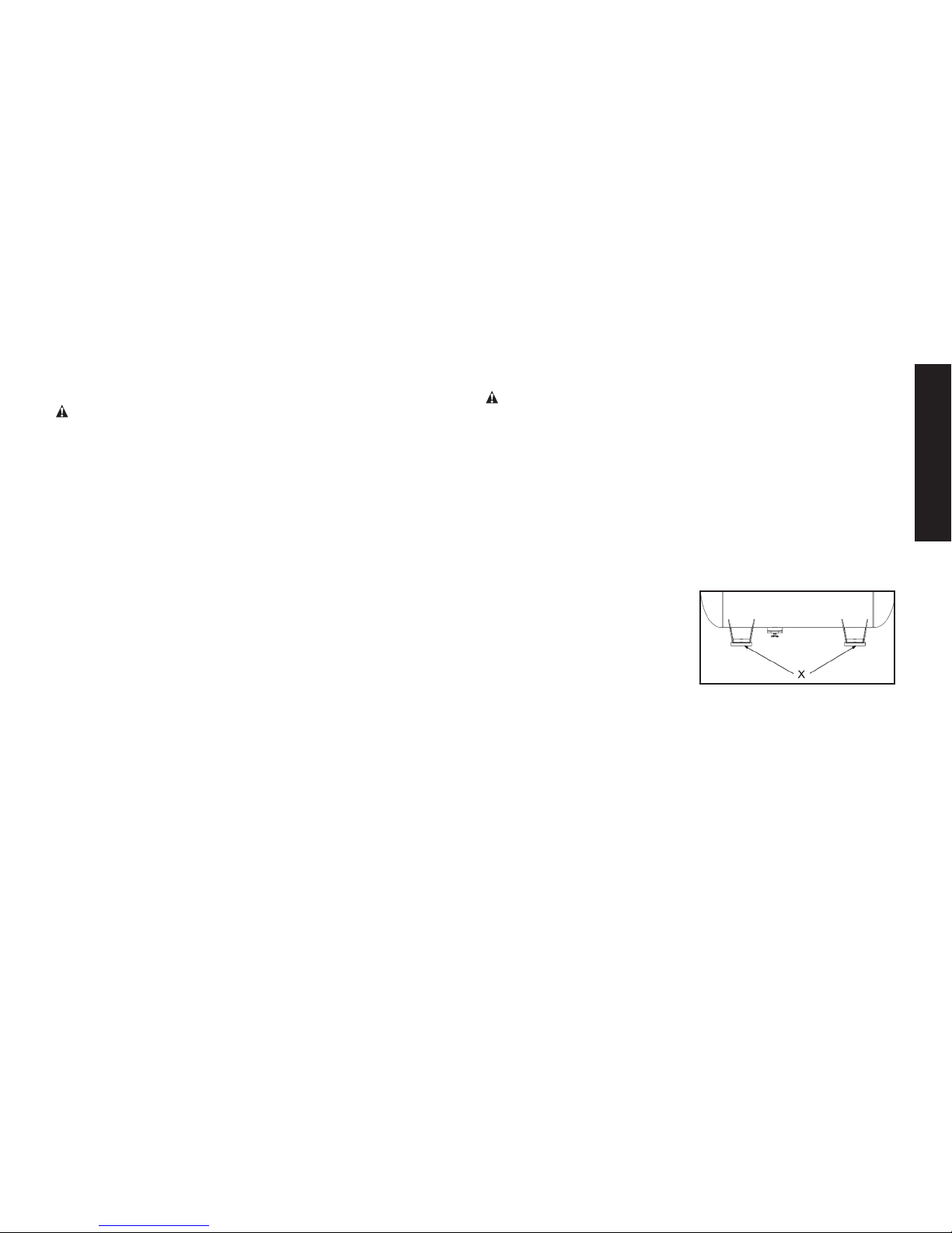
To prevent damage to tank and
pump, the tank must be shimmed
so the pump is level within 1/8”
per lineal foot maximum to
distribute oil properly. Fasten to
floor and NEVER force tank feet
to floor without shims when tightening. We also recommend the
use of vibration pads (094-0137) under tank feet (see X).
NOTE: If the compressor is mounted on a vehicle, the vehicle
must be parked on a level surface while operating the compressor.
This is to ensure proper lubrication of the pump and gasoline
engine.
Page 14

14
English
Connecting a Battery
1. Battery: A 12 volt sealed battery with a minimum ampere-
hour rating of 18 Ah is required (battery not included).
2. Batterycables: Select battery cables to avoid greater than
.05 volt drop in the cable during starter motor operation.
3. BatteryCablesizeandlength:(Gauge x length)
Positive Cable: AWG No. 4 x 1.5 m (5.0 ft) maximum.
Negative Cable: AWG No. 4 x 2.3 m (7.5 ft) maximum.
4. WiringPrecautions:
A. Connect the battery positive (+) cable to the starter
solenoid terminal.
B. Connect the battery negative (-) cable to the engine
crankcase or engine frame mounting bolt.
C. Do not route the battery cables on or near any hot,
moving or rotating parts or sharp edges. Keep the
battery cables and electrical wires away from the fuel
line.
D. Protect positive electrical connections with a cover or
insulation.
Failure to connect and disconnect in the proper sequence can
cause equipment damage. Ensure there is a clean tight fit from the
cables to the post.
WARNING: Remove the cable from the negative (-) side of
thebattery before servicing.
Servicing of batteries are to be performed or supervised by personnel knowledgeable of batteries and the required precautions. Keep
unauthorized personnel away from batteries.
Battery Safety Instructions
WARNING: Lead-acid batteries present a risk of fire because
they generate hydrogen gas. The following procedures are to be
followed:
• Donotsmokewhennearbatteries.
• Donotcauseflameorsparkinbatteryarea.
• Dischargestaticelectricityfrombodybeforetouching
batteries by first touching a grounded metal surface.
• Donotdisposeofbatteriesinafire.Thebatteryis
capable
of exploding.
• Donotopenormutilatethebatteryorbatteries.
Released electrolyte has been known to be harmful to
the skin and eyes and to be toxic.
WARNING: A battery presents a risk of electrical shock and
a high short circuit current. The following precautions are to be
observed when working on batteries:
• Removewatches,ringsorothermetalobjects.
• Usetoolswithinsulatedhandles.
• Wearrubbergloves.
• Donotlaytoolsormetalpartsontopofbatteries.
• Disconnectchargingsourcepriortoconnectingor
disconnecting battery terminals.
• Determineifthebatteryisinadvertentlygrounded.When
inadvertently grounded, remove source of ground.
Contact with any part of a grounded battery is capable of
resulting in electrical shock. The risk of such shock is
reduced when such grounds are removed during
installation and maintenance.
• Failuretoconnectanddisconnectinthepropersequence
can cause equipment damage. Ensure there is a clean
tight fit from the cables to the post.
Page 15
15
English
Pre-Start Checklist (refer to Fig. 1, pg. 2)
1. Ensure engine START/RUN/OFF switch (C) is in the OFF position.
2. Ensure air tank is drained, see Draining Air Tank under
Maintenance.
3. Ensure the drain valve (H) is closed.
4. Ensure safety valve (G) is functioning properly, see Checking
SafetyValve under Maintenance.
5. Check pump oil level, see Compressor Pump Oil under
Maintenance.
CAUTION:
Do not operate without oil or with inadequate oil.
DeWALT is not responsible for compressor failure caused by
inadequate oil.
6. Check engine's oil and fuel level, see engine's instruction manual
for correct procedures.
7. Visually inspect drive belt. Replace belt if frayed, cracked, or
worn
NOTE: Outer belt cover must be removed to inspect drive belt.
8. Ensure all guards, covers, and labels are in place, legible (for
labels) and securely mounted. Do not use compressor until all
items have been verified.
WARNING: Do not operate this unit until you read this
instruction manual and the engine instruction manual for safety,
operation and maintenance instructions.
Break-in Procedure
NOTICE: Risk of property damage. Serious damage may result if
the following break-in instructions are not closely followed.
Thisprocedureisrequired:
• Before the air compressor is used for the first time.
• When the check valve has been replaced.
• When the compressor pump has been replaced.
Theprocedure:
1. Follow Pre-StartChecklist.
2. Rotate the unloader's manual lock to the open position to
prevent air tank pressure buildup.
3. Prepare engine for first time use, see engine's instruction
manual for correct procedure.
4. Place the fuel valve lever (M) in the
OPEN
CLOSED
L
M
OFF
ON
ON postion.
5.
If the engine is cold, move the
choke (L) to the CLOSED position
as shown. If the engine is hot, move
the choke to the OPEN position.
6.
RecoilStart
:
a. Turn the engine START/RUN/OFF switch (C) to the RUN
position.
b.
WARNING: Risk of unsafe operation. Pull starter grip
slowly until resistance is felt. Then pull starter grip (N)
rapidly to avoid kickback and prevent hand or arm injury.
NOTE: Do not allow the starter grip to snap back. Return it gently
by hand.
ElectricStart
a. Connect a battery to the solenoid on the gas engine. See
ConnectingaBattery for procedure.
b. Place
engine START/RUN/OFF switch
(C) in the
START
position and hold until the engine starts.
NOTE: Do not hold the switch in the
START
position for more than
5 seconds. If the engine does not start, wait 10 seconds before
retrying. Failure to follow these instructions may result in damage
to the starter motor due to overheating.
c. When the engine starts, release the engine switch allowing it
Page 16

16
English
to return to the RUN position.
NOTE: Do not turn the engine switch to the
START
position while
the engine is running.
NOTE: If the oil level in the engine is low, the engine will not start. If
the engine does not start, check the oil level and add oil as needed.
NOTE: To ensure maximum oil lubrication, operate the unit on a
level surface.
7. As the engine warms up, move the choke to the OPEN position.
8. Run the air compressor for 30minutes to seat the rings and
lubricate all the internal surfaces. Ensure there is no pressure
build up in the air tank by observing the reading on the air tank
pressure gauge.
9. Rotate the manual lock on the unloader valve into the closed
position so the air tank pressure can build.
10. Compressed air will be available from the hose air outlet until it
is used up or bled off.
OPERATING PROCEDURES
Start-up (refer to Fig. 1, pg. 2)
WARNING: Do not operate this unit until you read this instruc-
tion manual and the engine instruction manual for safety, operation and maintenance instructions.
1. Follow Pre-StartChecklist.
2. Rotate the manual lock unloader lever to the open position to
assist with start up.
3. Place the fuel valve lever (M) in the ON postion.
4.
If the engine is cold, move the choke (L) to the CLOSED position
as shown. If the engine is hot, move the choke to the OPEN
position.
5. RecoilStart
:
a. Turn the engine START/RUN/OFF switch (C) to the RUN
position.
b.
WARNING: Risk of unsafe operation. Pull starter grip
slowly until resistance is felt. Then pull starter grip (N)
rapidly to avoid kickback and prevent hand or arm injury.
NOTE: Do not allow the starter grip to snap back. Return it gently
by hand.
ElectricStart
a. Connect a battery to the solenoid on the gas engine. See
ConnectingaBattery for procedure.
b. Place
engine START/RUN/OFF switch
(C) in the
START
position and hold until the engine starts.
NOTE: Do not hold the switch in the
START
position for more than 5
seconds. If the engine does not start, wait 10 seconds before retrying. Failure to follow these instructions may result in damage to the
starter motor due to overheating.
c. When the engine starts, release the engine switch allowing it
to return to the RUN position.
NOTE: Do not turn the engine switch to the
START
position while
the engine is running.
NOTE: If the oil level in the engine is low, the engine will not start. If
the engine does not start, check the oil level and add oil as needed.
NOTE: To ensure maximum oil lubrication, operate the unit on a
level surface.
6. As the engine warms up, move the choke to the OPEN position.
7. Rotate manual lock unloader lever to the closedposition to allow
air tank pressure to build. NOTE: Pump will not operate with the
manual lock unloader lever in the open position.
8. Allow compressor to pump up to blowoff pressure.
NOTE: If any unusual noise or vibration is noticed, stop the
compressor and refer to the troubleshooting section.
NOTE: The air compressor pump is capable of running continuously.
Page 17

17
English
To prolong the air compressor's life, it is recommended to run at high
throttle 50-75% of the run time and idle for 25% of the run time.
9. Attach hose and accessory.
WARNING: Risk of unsafe operation. Firmly grasp hose in hand
when installing or disconnecting to prevent hose whip.
WARNING: Risk of unsafe operation. Do not use damaged or
worn accessories.
CAUTION: Risk of unsafe operation. Compressed air from the
unit may contain wa ter condensation and oil mist. Do not spray
un fil tered air at an item that could be damaged by moisture. Some
air op er ated tools or de vic es may require filtered air. Read the
in struc tions for the air tool or device.
Shut-down
1. Place the engine START/RUN/OFF switch (C) to the OFF Position.
2. Place the fuel valve lever (M) in the OFF postion.
NOTE: If finished using compressor, follow Steps 3–5.
3. Remove hose and accessory.
4. Pull ring on safety valve (G) allowing air to bleed from the tank
until tank pressure is approximately 20 psi. Release safety
valve ring.
5. Drain the air tank.
See DrainingAirTank under Maintenance
.
WARNING: Risk of bursting. Drain air tank daily. Water will
condense in air tank. If not drained, water will corrode and weaken
the air tank causing a risk of air tank rupture.
OPEN
CLOSE
FIG. 3
MAINTENANCE (refer to Fig. 1, pg. 2)
The following procedures must be followed when maintenance or
service is performed on the air compressor.
1. Ensure engine START/RUN/OFF switch (C) is in the OFF position.
2. Disconnect spark plug wire.
3. Drain air tank.
4. Allow air compressor to cool down before starting service
NOTE: All compressed air systems contain maintenance parts (e.g.
oil, filters, separators) that are periodically replaced. These used parts
may contain substances that are regulated and must be disposed of in
accordance with local, state, and federal laws and regulations.
NOTE: Take note of the positions and locations of parts during
Page 18

18
English
disassembly to make reassembly easier.
NOTE: Any service operations not included in this section should
be performed by a DeWALT factory service center or a DeWALT
authorized service center.
MaintenanceChart
Procedure
Daily
Weekly
Monthly
1year
or 200
Hours
Seetank
warning
label
Check safety valve
X
Inspect air filter
X
+
Drain air tank
X
Check pump oil level
X
Change pump oil
X
**
+
Oil leak inspection
X
Inspect drive belt
X
Check drive belt tension
X
Check pulley/flywheel alignment
X
Check for unusual noise/vibration
X
Check for air leaks
X*
Clean compressor exterior
X
Remove tank from service
X
++
Engine See engine instruction manual.
* To check for air leaks apply a solution of soapy water around joints.
While compressor is pumping to pressure and after pressure cuts out,
look for air bubbles to form.
** The pump oil must be changed after the first 20 hours or operation.
Thereafter, when using
synth
etic blend non-detergent air compressor
oil, change oil every 200 hours of operation or once a year, whichever
comes first.
+ Perform more frequent in dusty or humid conditions.
++
For more information, call 1-888-895-4549 .
WARNING: To avoid personal injury, always shut off the
gasoline engine and relieve all air pressure from the system
before performing any service on the air compressor.
To ensure efficient operation and longer life of the air compressor
outfit, a routine maintenance schedule should be prepared and followed. The following routine maintenance schedule is geared to an
outfit in a normal working environment operating on a daily basis.
If necessary, the schedule should be modified to suit the conditions under which your compressor is used. The modifications will
depend upon the hours of operation and the working environment.
Compressor outfits in an extremely dirty and/or hostile environment
will require a greater frequency of all maintenance checks.
NOTE: See Operation section for the location of controls.
CheckingSafetyValve(refer to Fig. 1, pg. 2)
WARNING: Hot surfaces. Risk of burn. Tubes, pump head,
and surrounding parts are very hot, do not touch (see the Hot
Surfaces identified in Fig. 2). Allow compressor to cool prior to
servicing.
WARNING: Risk of bursting. If the safety valve does not work
properly, over-pressurization may occur, causing air tank rupture
or an explosion.
WARNING: Risk from flying objects. Always wear certified
safety equipment: ANSI Z87.1 eye protection (CAN/CSA Z94.3)
with side shields.
Page 19
19
English
Before starting compressor, pull the ring on the safety valve
to make sure that the safety valve operates freely. If the valve
is stuck or does not operate smoothly, it must be replaced with
the same type of valve.
Checking Air Filter
WARNING: Hot surfaces. Risk of burn. Tubes, pump head,
and surrounding parts are very hot, do not touch (see the Hot
Surfaces identified in Fig. 2). Allow compressor to cool prior to
servicing.
A dirty air filter will not allow the compressor to operate at full
capacity. Keep the air filter clean at all times.
1. Ensure engine START/RUN/OFF switch (C) is in the OFF position.
2. Allow unit to cool.
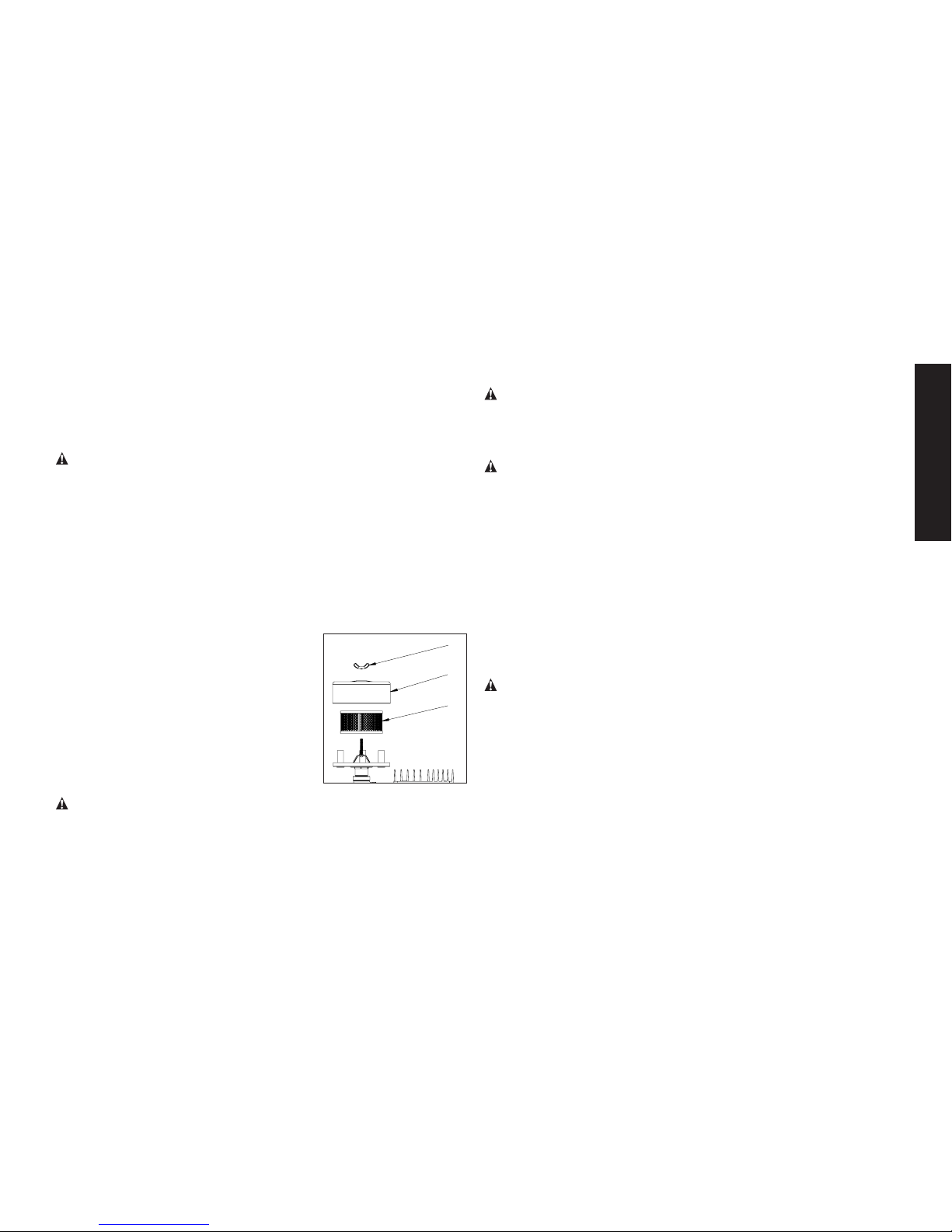
3. Remove the wing nut (P).
4. Remove the outer metal cover (Q).
5. Remove element (R) from filter base.
P
Q
R
6. If element needs cleaning, blow out
with air. Replace if needed. Purchase
replacement parts from your local dealer or authorized service center. Always
use identical replacement parts.
7. Place element back in filter base.
8. Place the outer metal cover back over
the filter element.
9. Secure with the wing nut.
CAUTION: Risk of unsafe operation. Do not operate without
air filter.
Draining Air Tank (refer to Fig. 3, pg. 17)
WARNING: Risk of unsafe operation. Air tanks contain high
pressure air. Keep face and other body parts away from outlet
of drain. Use eye protection [ANSI Z87.1 (CAN/CSA Z94.3)] when
draining as debris can be kicked up into face.
WARNING: Risk from noise. Use ear protection (ANSI S12.6
(S3.19) as air flow noise is loud when draining.
NOTE: All compressed air systems generate condensation that accumulates in any drain point (e.g., tanks, filter, aftercoolers, dryers). This
condensate contains lubricating oil and/or substances which may be
regulated and must be disposed of in accordance with local, state,
and federal laws and regulations.
1. Ensure engine START/RUN/OFF switch (C) is in the OFF position.
2. Pull ring on safety valve allowing air to bleed from the tank until
tank pressure is approximately 20 psi. Release safety valve ring.
3. Drain water from air tank by opening drain valve (counterclockwise) on bottom of tank.
WARNING: Risk of bursting. Water will condense in the air
tank. If not drained, water will corrode and weaken the air tank
causing a risk of air tank rupture.
NOTICE: Risk of property damage. Drain water from air tank may
contain oil and rust which can cause stains.
4. After the water has been drained, close the drain valve (clock-
wise).
NOTE: If drain valve is plugged, release all air pressure. The valve
can then be removed, cleaned, then reinstalled.
Page 20

20
English
Compressor Pump Oil (refer to Fig. 4, pg. 20)
WARNING: Hot surfaces. Risk of burn. Tubes, pump head,
and surrounding parts are very hot, do not touch (see the Hot
Surfaces identified in Fig. 2). Allow compressor to cool prior to
servicing.
NOTICE: Risk of property damage. Use air compressor oil only.
Multi-weight automotive engine oils like 10W30 should not be used
in air compressors. They leave carbon deposits on critical components, thus reducing performance and compressor life.
NOTE: Use synthetic blend non-detergent air compressor oil.
NOTE: Crankcase oil capacity is approximately 53 fluid ounces
(1567 ml).
Checking
1. Ensure engine START/RUN/OFF switch (C) is in the OFF
Position.
2. The oil level should be to the middle of the sight glass (S).
3. If needed remove oil fill plug (I) and slowly add oil until it reaches
the middle of the sight glass.
Changing
WARNING: Hot surfaces. Risk of burn. Tubes, pump head,
and surrounding parts are very hot, do not touch (see the Hot
Surfaces identified in Fig. 2). Allow compressor to cool prior to
servicing.
WARNING: Drain tank to release air pressure before removing
the oil fill cap or oil drain plug.
1. Ensure engine START/RUN/OFF switch (C) is in the OFF
position.
2. Allow the unit to cool.
3. Disconnect spark plug wire.
4. Drain air tank.
5. Remove the oil fill plug (I).
6. Remove the oil drain plug (J) and drain oil into a suitable container.
7. Replace the oil drain plug (J) and tighten securely
8. Slowly add compressor oil until it reaches the middle of the
sight glass (S). NOTE: When filling the crankcase, the oil flows
very slowly into the pump. If the oil is added too quickly, it will
overflow and appear to be full.
CAUTION: Overfilling with oil will cause premature compressor
failure. Do not overfill.
9. Replace oil fill plug (I) and tighten securely.
10. Reconnect spark plug wire.
NOTE: Pump oil contains substances that are regulated and must
be disposed of in accordance with local, state and federal laws and
regulations.
T=Full
U=Add
J=Oildrainplug
S=Oillevelsightglass
I=Oilfillplug
Fig. 4
J
I
S
Page 21
21
English
Belt Replacement
WARNING: To avoid personal injury, always shut off the
gasoline engine and relieve all air pressure from the system
before performing any service on the air compressor. Do not
use the unit with the shrouds or belt guard removed. Serious
injury could occur from contact with moving parts. Hot
surfaces. Risk of burn. Pump head, and surrounding parts are
very hot, do not touch (see the Hot Surfaces identified in Fig.
2). Allow compressor to cool prior to servicing.
1. Ensure engine START/RUN/OFF switch (C) is in the OFF
position.
2. Allow the unit to cool.
3. Disconnect spark plug wire.
4. Drain air tank.
5. Remove the front of the
V
beltguard by removing
the screws and washers (V) using a Torx T25
bit.
6. Mark pump position on
saddle.
7. Loosen the engine
mounting screws and
slide the engine toward
the air compressor.
8. Remove the belt and replace with a new one.
9. See the Adjusting Belt Tension before tightening engine
mounting screws.
10. Reconnect spark plug wire.
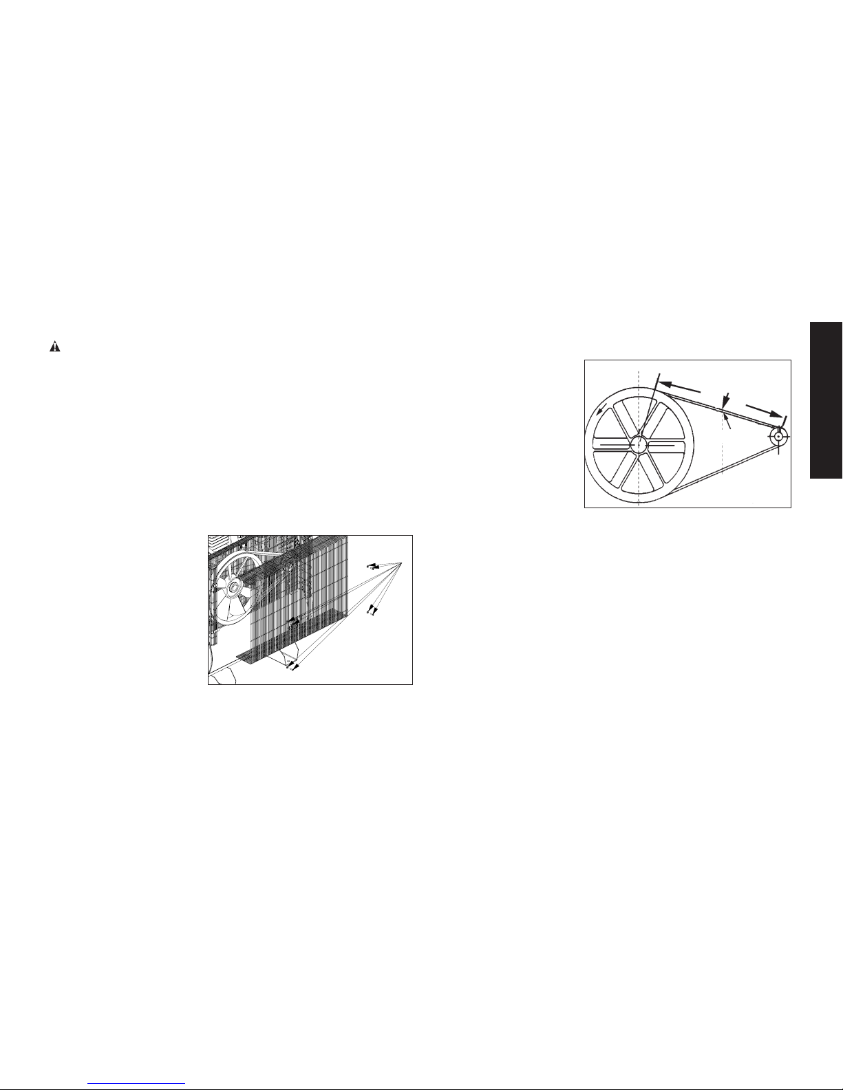
Adjusting Belt Tension
1. Ensure engine START/RUN/OFF switch (C) is in the OFF
position.
2. Allow the unit to cool.
Downward Force
Deflection
3. Disconnect spark plug
wire.
4. Drain air tank.
5. Slide engine into
original position, line
the engine up with the
mark made earlier on
saddle.
6. Tighten two outside
engine mounting screws enough to hold the engine in place for
checking pulley and flywheel alignment.
7. The belt should deflect 1/2” (13mm)at midway between the
pulley and the flywheel when a 10 pound (4.6kg.) weight is
applied at the midway point.
8. When proper belt tension is achieved, tighten all
four engine mounting screws. Torque to 15-22 ft-lbs
(20.3–29.8 Nm).
9. Reconnect spark plug wire.
Pulley and Fly wheel Alignment
NOTE: Once the engine pulley has been moved from its factory set
location, the grooves of the flywheel and pulley must be aligned to
within 1/16” (1.6 mm) to prevent excessive belt wear.
The air compressor flywheel and engine pulley must be in-line
(in the same plane) within 1/16” (1.6 mm) to assure belt retention
within flywheel belt grooves. To check alignment, perform the following steps:
Page 22
22
English
1. Ensure engine START/RUN/OFF switch (C) is in the OFF
Position.
2. Allow the unit to cool.
3. Disconnect spark plug wire.
4. Drain air tank.
5. Remove belt guard.
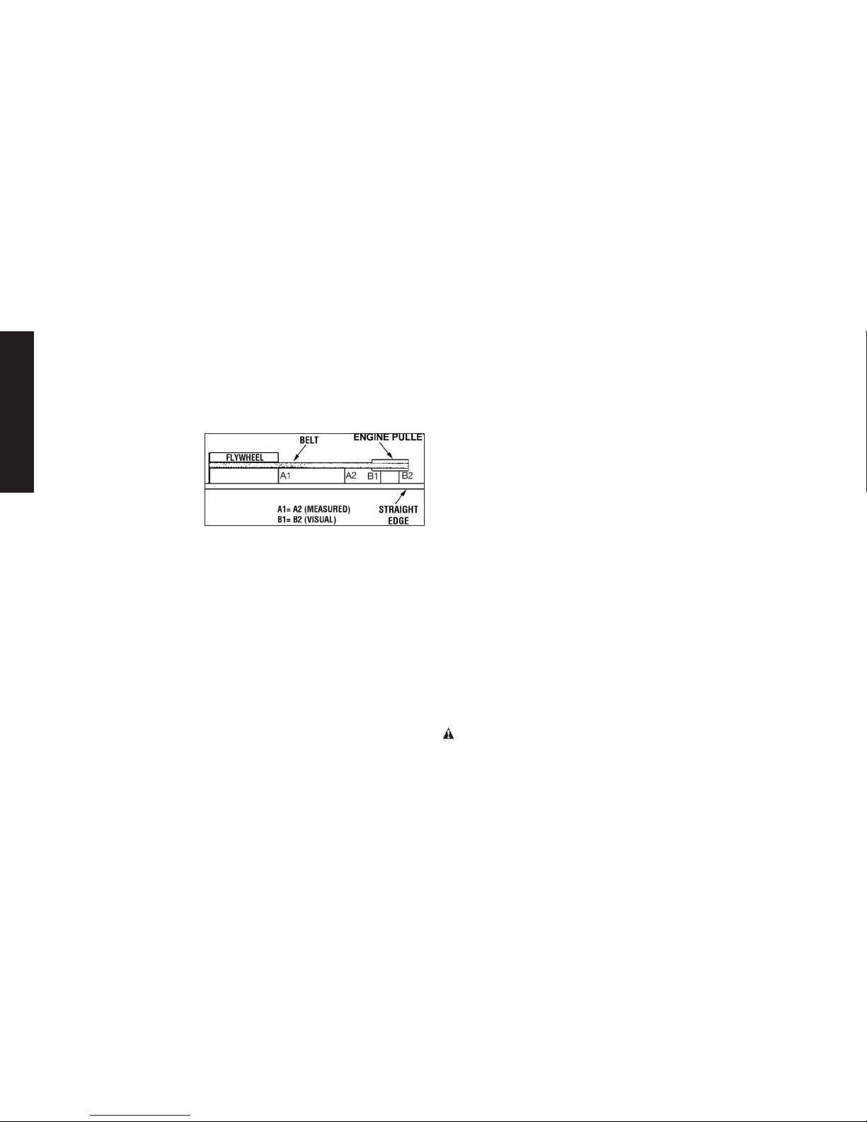
6. Place a straightedge
against the outside of
the flywheel and the
engine drive pulley.
7. Measure the distance
between the edge
of the belt and the
straightedge at points
A1 and A2 in figure. The difference between measurements
should be no more than 1/16” (1.6 mm).
8. If the difference is greater than 1/16” (1.6 mm) loosen the set
screw holding the engine drive pulley to the shaft and adjust the
pulley’s position on the shaft until the A1 and A2 measurements
are within 1/16” (1.6 mm) of each other.
9. Tighten the engine drive pulley set screw.
10. Visually inspect the engine drive pulley to verify that it is perpendicular to the drive engine shaft. Points B1 and B2 of Figure
should appear to be equal. If they are not, loosen the setscrew
of the engine drive pulley and equalize B1 and B2, using care
not to disturb the belt alignment performed in step 2.
11. Retighten the engine drive pulley setscrew. Torque to
145–180in lbs (16.4–20.3Nm).
12. Reinstall belt guard.
13. Reconnect spark plug wire.
Air Compressor Pump Intake and Exhaust
Valves
Once a year have a Trained Service Technician check the air compressor pump intake and exhaust valves.
Inspect Air Lines and Fittings for Leaks
1. Ensure engine START/RUN/OFF switch (C) is in the OFF
Position.
2. Allow the unit to cool.
3. Disconnect spark plug wire.
4. Apply a soap solution to all air line fittings and connections/
piping.
5. Correct any leaks found.
6. Reconnect spark plug wire.
IMPORTANT: Even minor leaks can cause the air compressor
to overwork, resulting in premature breakdown or inadequate
performance.
Air compressor Head Bolts - Torquing
The air compressor pump head bolts should be kept properly
torqued. Check the torques of the head bolts after the first five
hours of operation. Torque to 32-37ft.-lbs. (43.4-50.2 Nm).
Service and Adjustments
ALL MAINTENANCE AND REPAIR OPERATIONS NOT LISTED
MUST BE PERFORMED BY TRAINED SERVICE TECHNICIAN.
WARNING: To avoid personal injury, always shut off the gasoline engine and relieve all air pressure from the system before
performing any service on the air compressor. Do not use the
unit with the shrouds or belt guard removed. Serious injury could
Page 23
23
English
occur from contact with moving parts. Hot surfaces. Risk of burn.
Pump head, and surrounding parts are very hot, do not touch (see
the Hot Surfaces identified in Fig. 2). Allow compressor to cool
prior to servicing.
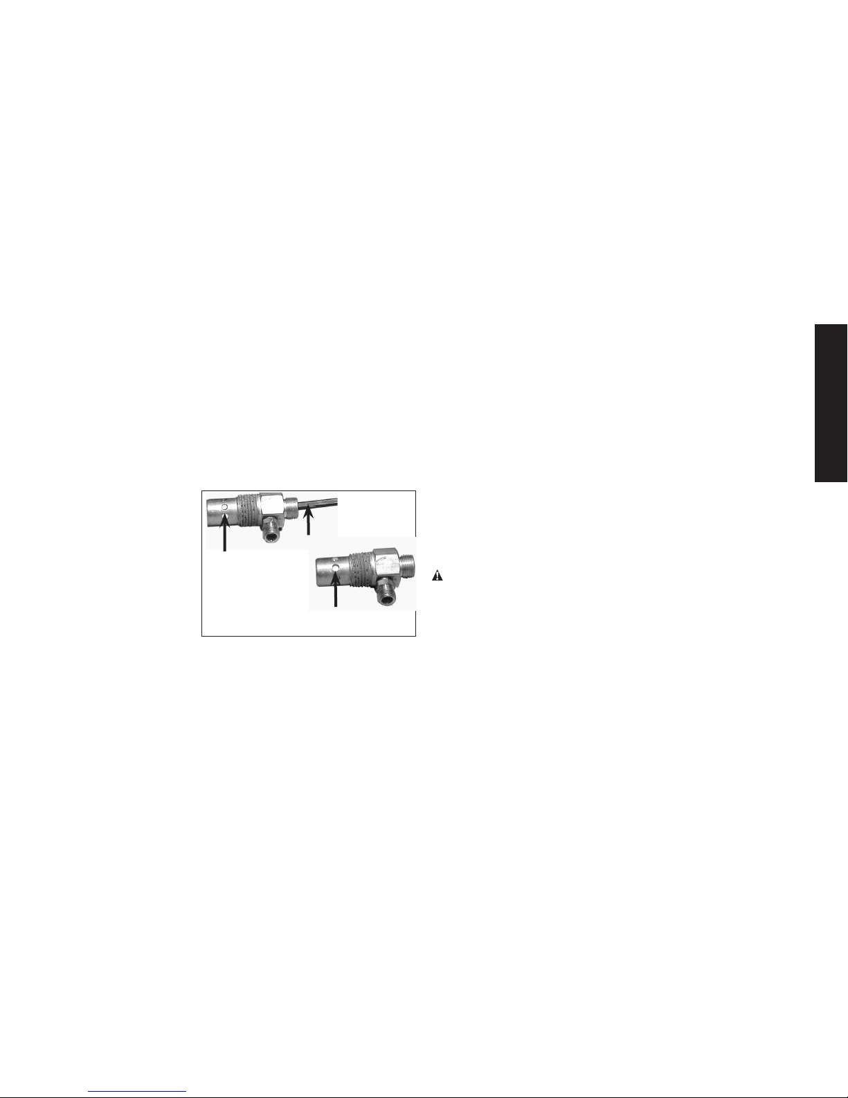
ToReplaceorCleanCheckValve
1. Ensure engine START/RUN/OFF switch (C) is in the OFF
Position.
2. Allow the unit to cool.
3. Disconnect spark plug wire.
4. Release all air pressure from air tank. See Draining Air Tank in
the Maintenance section.
5. Using an adjustable
In closed position
disc is visible.
In open
position
nothing is
visible.
Screwdriver
wrench loosen outlet
tube nut at air tank and
pump. Carefully move
outlet tube away from
check valve.
6. Using an adjustable
wrench loosen pressure relief tube nut
at air tank. Carefully
move pressure relief
tube away from check valve.
7. Unscrew the check valve (turn counterclockwise) using a 7/8”
open end wrench. NOTE the orientation for reassembly.
8. Using a screwdriver, carefully push the valve disc up and down.
NOTE: The valve disc should move freely up and down on a
spring which holds the valve disc in the closed position, if not
the check valve needs to be cleaned or replaced.
9. Clean or replace the check valve. A solvent, such as paint or
varnish remover can be used to clean the check valve.
10. Apply sealant to the check valve threads. Reinstall the check
valve (turn clockwise).
11. Replace the pressure release tube. Tighten nuts.
12. Replace the outlet tube and tighten nuts.
13. Reconnect spark plug wire.
14. Perform the Break-in Procedure. See Break-in Procedure in
the Operation section.
Additional Service
Disassembly or service of the air compressor beyond what is covered in this manual is not recommended. If additional service is
required, contact your nearest Authorized Warranty Service Center.
Accessories
Recommended accessories for use with your tool are available for
purchase from your local dealer or authorized service center. If you
need assistance in locating any accessory for your tool, please call
1-888-895-4549 or visit our website www.dewalt.com.
WARNING: The use of any other accessory not recommended
for use with this tool could be hazardous. Use only accessories
rated equal to or higher than the rating of the air compressor.
Service Information
Please have the following information available for all service calls:
Model Number ____________ Serial Number ___________
Date and Place of Purchase ____________________________
Repairs
To assure product SAFETY and RELIABILITY, repairs, maintenance
and adjustment should be performed by a DeWALT factory service
center, a DeWALT authorized service center or other qualified
service personnel. Always use identical replacement parts.
Page 24

24
English
Limited Warranty
DEWALT Industrial Tools are warranted from date of purchase.
2 Year – Limited warranty on oil-lubricated air compressor
pumps.
1 Year – Limited warranty on all other air compressor
components. This warranty is not transferable to
subsequent owners.
DEWALT will repair or replace, without charge, at DEWALT’s
option, any defects due to faulty materials or workmanship.
For further detail of warranty coverage and warranty repair
information, call 1-(888)-895-4549 or visit dewalt.com. This
warranty does not apply to accessories or damage caused where
repairs have been made or attempted by others. This warranty
also does not apply to merchandise sold by DEWALT which has
been manufactured by and identied as the product of another
company, such as gasoline engines. Such manufacturer’s
warranty, if any, will apply. ANY INCIDENTAL, INDIRECT OR
CONSEQUENTIAL LOSS, DAMAGE OR EXPENSE THAT MAY
RESULT FROM ANY DEFECT, FAILURE OR MALFUNCTION OF
THE PRODUCT IS NOT COVERED BY THIS WARRANTY. Some
states do not allow the exclusion of limitation of incidental or
consequential damages, so the above limitation or exclusion may
not apply to you. IMPLIED WARRANTIES, INCLUDING THOSE
OF MERCHANTABILITY OR FITNESS FOR A PARTICULAR
PURPOSE, ARE LIMITED TO ONE YEAR FROM THE DATE OF
ORIGINAL PURCHASE. Some states do not allow limitations on
how long an implied warranty lasts, so the above limitations may
not apply to you.
What the Company Will Do: (the company) will cover parts
and labor to remedy substantial defects due to materials
and workmanship during the rst year of ownership, with the
exceptions noted below. Parts used in repair of whole goods or
accessories are warranted for the balance of the original warranty
period.
What is not covered Under This Warranty? Failures by the
original retail purchaser to install, maintain, and operate said
equipment in accordance with standard industry practices.
Modications to the product, or tampering with components,
or failure to comply with the specic recommendations of the
Company set forth in the owner’s manual, will render this warranty
null and void. The Company shall not be liable for any repairs,
replacements, or adjustments to the equipment, or any costs for
labor performed by the purchaser without the Company’s prior
written approval. The effects of corrosion, erosion, surrounding
environmental conditions, cosmetic defects, and routine
maintenance items, are specically excluded from this warranty.
Routine maintenance items such as: oil, lubricants, and air lters,
as well as changing oil, air lters, belt tensioning, etc… fall under
the owner’s responsibility. Additional exclusions include: freight
damage, failures resulting from neglect, accident, or abuse,
induction motors when operated from a generator, oil leaks, air
leaks, oil consumption, leaky ttings, hoses, petcocks, bleeder
tubes, and transfer tubes.
• The following components are considered normal wear
items and are not covered after the rst year of
ownership: Belts, sheaves, ywheels, check valves,
pressure switches, air unloaders, throttle controls,
electric motors, brushes, regulators, o-rings, pressure
gauges, tubing, piping, ttings, fasteners, wheels, quick
couplers, gaskets, seals, air lter housings, piston rings,
connecting rods, and piston seals.
• Labor, service calls, and travel charges, are not covered
Page 25

25
English
after the rst year of ownership on stationary
compressors (compressors without handles, or wheels).
Repairs requiring overtime, weekend rates, or any other
charges beyond the standard shop labor rate are not
covered.
• Time required for orientation training for the service
center to gain access to the product, or additional time
due to inadequate egress.
• Damage caused by incorrect voltage, improperly wired,
or failure to have a certied licensed electrician install
the compressor, will render this warranty null and void.
• Damage caused from inadequate lter maintenance.
• Pump wear or valve damage caused by using oil not
specied.
• Pump wear or damage caused by any oil contamination.
• Pump wear or valve damage caused by failure to follow
proper maintenance guidelines.
• Operation below proper oil level or operation without oil.
• Gas Engines, if product is equipped with a gas engine,
see engine manual for specic engine manufacturer’s
warranty coverage.
Parts purchased separately: The warranty for parts purchased
separately such as: pumps, motors, etc., are as follows:
From Date of Purchase
• All single & two stage pumps 1 year
• Electric motors 90 days
• Universal motor/pump 30 days
• All other parts 30 days
• No return authorization will be issued for electrical
components once items are installed.
How do You Get Service? In order to be eligible for service
under this warranty you must be the original retail purchaser,
and provide proof of purchase from one of the Company’s
dealers, distributors, or retail outlet stores. Portable compressors
or components must be delivered, or shipped, to the nearest
Authorized Service Center. All associated freight costs and travel
charges must be borne by the consumer. Please call our toll free
number 1-888-895-4549 for assistance.
THIS WARRANTY GIVES YOU SPECIFIC LEGAL RIGHTS, AND
YOU MAY ALSO HAVE OTHER RIGHTS WHICH VARY FROM
STATE TO STATE.
THE COMPANY MAKES NO OTHER WARRANTY OR
REPRESENTATION OF ANY KIND WHATSOEVER,
EXPRESSED OR IMPLIED, EXCEPT THAT OF TITLE. ALL
IMPLIED WARRANTIES, INCLUDING ANY WARRANTY OF
MERCHANTABILITY AND FITNESS FOR PARTICULAR PURPOSE
ARE HEREBY DISCLAIMED. LIABILITY FOR CONSEQUENTIAL
AND INCIDENTAL DAMAGES UNDER ANY AND ALL
WARRANTIES, OTHER CONTRACTS, NEGLEGENCE, OR
OTHER TORTS IS EXCLUDED TO THE EXTENT EXCLUSION IS
PERMITTED BY LAW.
Page 26

26
English
Troubleshooting Guide
This section provides a list of the more frequently encountered malfunctions, their causes and corrective actions. The operator or
maintenance personnel can perform some corrective actions, and others may require the assistance of a qualified DeWALT technician or
your dealer.
Excessive air tank pressure-safety valve pops off ......................................................................1
Air leaks .................................................................................................................................... 2
Continuous air leak at unloader valve. ...................................................................................... 3
Air leaks in air tank or at air tank welds .................................................................................... 4
Air leaks between head and valve plate ....................................................................................5
Air leaks from safety valve .........................................................................................................6
Compressor is not supplying enough air to operate accessories ............................................ 2, 7, 8, 9, 10, 12, 13
Restricted air intake. .................................................................................................................. 12
Excessive vibration .................................................................................................................... 14, 15
Knocking Noise ......................................................................................................................... 13, 14, 15, 16, 17, 18, 19
Excessive belt wear ................................................................................................................... 13,14,16,19,20
Squealing sound ........................................................................................................................ 13
Engine will not run ..................................................................................................................... 22, 24, 30
Moisture in pump crankcase ..................................................................................................... 5, 11, 23, 24, 25, 26, 27, 28
Pump will not run.......................................................................................................................29
Air tank pressure will not build .................................................................................................. 29
Troubleshooting Codes
CODE POSSIBLE CAUSE POSSIBLE SOLUTION
1 Unloader valve does not release pressure when air
tank reaches blow-offpressure
Unloader valve must be replaced. Contact a DeWALT factory service center or a DeWALT authorized service center.
2 Fittings are not tight Tighten fittings where air can be heard escaping. Check fittings
with soapy water solution. DO NOT OVERTIGHTEN.
Page 27

27
English
CODE POSSIBLE CAUSE POSSIBLE SOLUTION
3 Defective unloader valve
Turn off engine, rotate manual lock unloader lever to the closed
perpendicular position. If air leaks out of air tank through unloader
valve, replace unloader valve.
4 Defective air tank Air tank must be replaced. Do not repair the leak.
WARNING: Risk of bursting. Do not drill into, weld or otherwise modify air tank or it will weaken. The air tank can rupture
or explode.
5 Leaking seals Contact a DeWALT factory service center or a DeWALT authorized
service center.
6 Defective safety valve Operate safety valve manually by pulling on ring. If valve still
leaks, it must be replaced.
7 Prolonged excessive use of air Decrease amount of air usage.
8 Compressor is not large enough for accessory Check the accessory air requirement. If it is higher than the SCFM
or pressure supplied by your air compressor, a larger compressor
is needed to operate accessory.
9 Hole in air hose Check and replace air hose, if required.
10 Unloader valve restricted Remove, clean or replace.
11 Unit operating in damp or humid conditions Move unit to a dry well ventilated area.
12 Restricted air intake filter Clean or replace air intake filter.
13 Loose belt
Check belt tension, see Adjusting Belt Tension under
Maintenance.
Page 28

28
English
CODE POSSIBLE CAUSE POSSIBLE SOLUTION
14 Engine mount ing bolts are loose Tighten mounting screws. Torque engine mounting bolts to
15– 22 ft-lbs (20.3– 29.8 Nm).
WARNING: Risk of bursting. Excessive vibration could weaken
the air tank and cause it to rupture or explode. Mounting screws
must be kept tightened.
15 Pump stabilizer bracket bolts are loose Check bolt and tighten if required. Torque pump stabilizer bracket
bolt to 15– 22 ft-lbs (20.3-29.8 Nm).
WARNING: Risk of bursting. Excessive vibration could weaken the air tank and cause it to rupture or explode. Stabilizer
bracket bolt must be kept tightened. Never operate the unit
unless equipped with the stabilizer bracket.
16
Loose pulley Tighten pulley set screw, torque to 145–180 in.-lbs. (16.4– 20.3Nm).
17
Loose flywheel Tighten flywheel screw, torque to 15–18 ft.-lbs.
(20.3–24.4 Nm).
18
Carbon build-up in pump Contact a DeWALT factory service center or a DeWALT authorized
service center.
19
Belt to tight
Check belt tension, see Adjusting Belt Tension under
Maintenance.
20
Pulley misalignment
See MotorPulley/FlywheelAlignmentunder Maintenance.
21
Engine problem Contact a DeWALT factory service center or a DeWALT authorized
service center.
22
Engine or pump oil is low
Add DeWALT synthetic compressor oil to pump. See Compressor
PumpOil under Maintenance.
Page 29

29
English
CODE POSSIBLE CAUSE POSSIBLE SOLUTION
23
Detergent type oil being used in pump Drain oil and refill pump with synthetic blend non-detergent air
compressor oil.
24
Extremely light duty cycles Run unit for longer duty cycles. It is recommended to run at high
throttle 50-75% of the run time and idle for 25% of the run time.
25
Piston rings damaged or worn Contact a DeWALT factory service center or a DeWALT authorized
service center.
26
Cylinder or piston damaged or worn Contact a DeWALT factory service center or a DeWALT authorized
service center.
27
Compressor cylinder finish worn Contact a DeWALT factory service center or a DeWALT authorized
service center.
28
Water in pump oil Drain oil and refill pump with synthetic blend non-detergent air
compressor oil.
29
Manual lock unloader lever in open position Rotate manual lock unloader lever to the closed perpendicular
position.
30
Engine fuel tank empty Add gasoline, see engine's instruction manual for correct proce-
dure.
Page 30
30
English
GLOSSARY
CFM: Cubic feet per minute.
SCFM: Standard cubic feet per minute; a unit of measure of air
delivery.
PSI: Pounds per square inch; a unit of measure of pressure.
Code Certification: Products that bear one or more of the fol-
lowing marks: UL®*, CUL, ETL®*, CETL, have been evaluated by
OSHA certified independent safety laboratories and meet the
applicable Standards for Safety.
*UL® is a registered trademark of Underwriters Laboratories and
ETL® is a registered trademark of Electrical Testing Laboratories.
CaliforniaCode: Unit may comply with California Code 462 (l) (2)/
(M) (2). Specification/model label is on the side of the air tank on
units that comply with California Code.
UnloaderBlow-OffPressure: All models are continuous running
units controlled by air tank pressure. When the maximum air tank
pressure is obtained, the unloader valve will blow-off. This will
cause the compressor to exhaust the air to the atmosphere and
not the tank. This decreases the load on the engine and allows it
to run at a near no-load condition.
UnloaderReset Pressure: When the air tank pressure drops to
a predetermined point, the unloader valve closes. The air tank
pressure will now increase until it reaches the unloader blow-off
pressure.
FREE WARNING LABEL REPLACEMENT: If your warning labels
become illegible or are missing, call 1-888-895-4549 for a free
replacement.
Page 31

31
Français
A. Filtre d’admission d’air de la pompe
B. Filtre d’admission d’air du moteur
C. Commutateur START (démarrage)/RUN (marche)/OFF (arrêt) du
moteur
D. Manomètre du réservoir d’air
E. Sortie d’air
F. Soupape de décompression
G. Soupape de sûreté
H. Soupape de purge du réservoir d’air
I. Jauge graduée de l’huile de la pompe/Bouchon de
remplissage d’huile
J. Bouchon de vidange d’huile de la pompe
K. Étrangleur fixe
L. Commande d’étrangleur
M. Levier du robinet à essence
N. Poignée du démarreur
O. Clapet
Caractéristiques techniques de la pompe
Deux cylindres
Deux-étagée
Lubrifiée à l’huile
Carter en fonte et piston et culasse en
Poids : 62 kg (136 lb)
Capacité en huile : 1567 ml (53 onces)
Compresseur d’air
Caractéristiques techniques du moteur
Honda 389 cc
Combustion interne
4 temps
Régime élevé 3600
Fiche technique
MODÈLE
DXCMH1393075
POIDS
225,4 kg (497 lb)
HAUTEUR
1178.6 mm (46.4”)
LARGEUR
495.3 mm (19.5")
LONGUEUR
1066.8 mm (42")
CAPACITÉ DU RÉSERVOIR D’AIR
113,6 liters (30 gallons)
ENV. PRESSION DE ÉCLENCHEMENT
175 psi
Page 32

32
Français
FIG. 1
A
I
J
G
D
E
H
F
N
M
L
K
B
C
O
Surfaces chaudes
FIG. 2
TUBES DE
SORTIE
TÊTE DE POMPE ET
CYLINDRE
CARTER DE
LA POMPE
MOTEUR À
ESSENCE
MOTEUR À
ESSENCE
Page 33

33
Français
POUR TOUTES QUESTIONS OU COMMENTAIRES RELATIFS(VES)
À L’OUTIL OU À PROPOS DE TOUT AUTRE OUTIL DEWALT,
COMPOSER SANS FRAIS LE : 1-888-895-4549
Directives de sécurité importantes
DANGER : Monoxyde de carbone. Le fonctionnement
d’un moteur à l’intérieur vous tuera en quelques minutes.
L’échappement du moteur contient des niveaux élevés de
monoxyde de carbone (CO), un gaz toxique, inodore et
invisible. Il est possible que vous inhaliez du CO même EN
L’ABSENCE de l’odeur de l’échappement du moteur.
• NE JAMAIS utiliser un moteur à l’intérieur d’une habitation,
d’un garage, d’un vide sanitaire ou de tout espace partiellement clos. Ces endroits peuvent accumuler des niveaux mortels de monoxyde de carbone. L’utilisation d’un ventilateur
Dénitions : lignes directrices en matière
de sécurité
Les définitions ci-dessous décrivent le niveau de gravité pour
chaque symbole. Veuillez lire le mode d’emploi et porter une
attention particulière à ces symboles.
DANGER : Indique une situation dangereuse imminente qui, si
elle n’est pas évitée, causera la mort ou des blessures graves.
AVERTISSEMENT:
Indique une situation potentiellement
dangereuse qui, si elle n’est pas évitée, pourrait se solder par un
décès ou des blessures graves.
ATTENTION : Indique une situation potentiellement dangereuse
qui, si elle n’est pas évitée pourrait se solder par des blessures
mineures ou modérées.
AVIS: Indique une pratique ne posant aucun risque de
dommages corporels mais qui par contre, si rien n’est fait pour
l’éviter, pourrait poser des risques de dommages matériels.
ou l’ouverture des fenêtres et portes NE FOURNIT pas assez
d’air frais.
• Utiliser UNIQUEMENT à l’extérieur et loin de fenêtres,
portes et évents ouverts. En effets, ces ouvertures peuvent
aspirer l’échappement du moteur à l’intérieur d’un espace.
• Même lors de l’utilisation correcte du moteur, le CO pourrait
pénétrer dans votre maison. TOUJOURS utiliser un avertisseur de CO alimenté à pile ou un avertisseur de CO de
secours à pile (non fourni) dans la maison. Lire et respecter
toutes les directives de l’avertisseur de CO avant son utilisation. En cas de malaise, d’étourdissement ou de faibles-
se, à tout moment, se déplacer à l’air frais immédiatement.
Consulter un médecin. Ce sont des signes d’intoxication par
le monoxyde de carbone.
AVERTISSEMENT: Ne pas utiliser l’appareil avant d’avoir lu le
mode d’emploi, et celui du moteur ainsi que l’intégralité des directives de sécurité, d’utilisation et d’entretien.
AVERTISSEMENT : Il est possible que le produit ne soit pas
doté d’un silencieux avec pare-étincelles. Si le produit n’en est
pas doté et qu’il est destiné à être utilisé près de matières inflammables ou sur un terrain cultivé ou couvert d’arbres, arbustes,
herbes ou autres matières similaires, alors l’installation d’un pareétincelles homologué est obligatoire et exigée par la loi dans l’État
de Californie. L’absence de pare-étincelles est en violation des
articles 130050 et/ou articles 4442 et 4443 du California Public
Resources Code, à moins que le moteur ne soit muni d’un pareétincelles comme stipulé à l’article 4442 et tenu en bon état de
fonctionnement. Les pare-étincelles sont exigés sur certaines
terres du Service des forêts américain et peuvent être également
exigés par d’autres législations ou ordonnances.
AVERTISSEMENT :
Ce produit contient des produits chi-
miques, reconnus par l’État de Californie comme étant can-
Page 34

34
Français
cérigènes et pouvant entraîner des anomalies congénitales et
d’autres dangers relatifs à la reproduction.
Se laver les mains
après toute manipulation.
AVERTISSEMENT:
Ce produit contient des produits chimiques
reconnus par l’État de la Californie comme étant cancérigènes et
pouvant entraîner des anomalies congénitales ou d’autres problèmes liés aux fonctions reproductrices. Se laver les mains après
toute manipulation.
AVERTISSEMENT :
Certaines poussières contiennent des
produits chimiques reconnus par l’État de la Californie comme
cancérigènes et pouvant entraîner des anomalies congénitales
et d’autres problèmes liés aux fonctions reproductrices, tels que
l’amiante et le plomb contenus dans les peintures au plomb.
CONSERVERCESDIRECTIVES
DANGER :
RISQUE D’EXPLOSION OU D’INCENDIE
CE QUI PEUT SE PRODUIRE COMMENT L’ÉVITER
• L’essence renversée et ses
vapeurs peuvent s’enflammer
à partir d’étincelles de
cigarettes, d’arcs électriques,
de gaz d’échappement et
de composants chauds du
moteur comme le silencieux.
• Éteindre le moteur et le laisser
refroidir avant de faire l’appoint
d’essence.
• Être attentif et éviter de
déverser de l’essence lors
du remplissage du réservoir.
Déplacer l’appareil hors de la
zone de remplissage avant de
démarrer le moteur.
• Le combustible du réservoir
se dilate sous l’effet de la
chaleur et pourrait se solder
par un déversement et un
incendie ou une explosion.
• Pour permettre l’effet de
dilatation, laisser 12,7 mm
(1/2 po) de dégagement sous le
bord du goulot de remplissage
lors du plein d’essence.
• Lesmatériauxcombustibles
quitouchentlespièces
chaudesdumoteurrisquent
des’enflammer.
• Faire le plein d’essence à
l’extérieur dans une zone bien
aérée. S’assurer de l’absence
de source d’inflammation près
de la zone de ravitaillement,
comme des cigarettes.
• Utiliser le compresseur dans
une zone propre, sèche et
bien aérée à une distance d’au
moins 1,22 mètres (48 po) de
tout édifice, objet ou mur. Ne
pas utiliser l’appareil à l’intérieur
ou dans un endroit exigu.
• L’utiliser uniquement dans
un endroit ouvert loin de
broussailles ou d’herbes sèches
ou de tout autre matériel
combustible.
Page 35

35
Français
• De l’essence mal entreposée
pourrait provoquer un
allumage (incendie)
accidentel. Ranger l’essence
de façon sécuritaire pour en
empêcher l’accès aux enfants
et à toutes autres personnes
non qualifiées.
• Entreposer l’essence dans
un contenant homologué par
l’OSHA (Santé et sécurité du
travail) dans un emplacement
sécuritaire loin de la zone de
travail.
• Lefonctionnementdece
produitsanssurveillance
pourraitsesolderpardes
blessurespersonnelles
oudesdommagesàla
propriété.Afinderéduire
lerisqued’incendie,ne
paslaisserlecompresseur
fonctionnersans
surveillance.
• Être toujours présent lorsque le
produit est en marche.
DANGER : RISQUE REPIRATOIRE (ASPHYXIE)
CE QUI PEUT SE PRODUIRE COMMENT L’ÉVITER
• Il est dangereux de respirer
l’air comprimé sortant du
compresseur. Le flux d’air
peut contenir du monoxyde
de carbone, des vapeurs
toxiques ou des particules
solides provenant du réservoir
d’air. La respiration de ces
contaminants peut causer de
sérieuses blessures, voire la
mort.
• Ne jamais utiliser l’air obtenu
directement du compresseur
pour l’alimentation en air
destinée à la consommation
humaine. Le compresseur
n’est pas muni de filtres et
d’équipement de sécurité
en ligne qui conviennent à la
consommation humaine.
•
Une exposition aux produits
chimiques présents dans la
poussière générée par les
activités de ponçage, sciage,
meulage, perçage et autres,
peut être nocive
•
Les matériaux vaporisés
comme la peinture, les
solvants de peinture, les
décapants, les insecticides,
les herbicides, pourraient
contenir des vapeurs
nocives et du poison.
•
Travailler dans un endroit
ayant une bonne aération
transversale. Lire et respecter
les directives en matière
de sécurité imprimées sur
l’étiquette ou les fiches
signalétiques des matériaux
qui sont pulvérisés. Toujours
utiliser un équipement de
sécurité homologué : une
protection respiratoire
conforme aux normes
NIOSH/OSHA, ou un masque
facial bien ajusté, conçus
spécifiquement pour votre
utilisation particulière.
Page 36

36
Français
DANGER : RISQUE D’ÉCLATEMENT
Réservoird’air comprimé:Le 26 février 2002, la U.S. Consumer
Product Safety Commission américaine a publié la règle nº 02-108
portant sur la sécurité en matière de réservoir d’air comprimé des
compresseurs:
Les réservoirs d’air comprimé des compresseurs n’ont pas une
durée de vie illimitée. La durée de vie des réservoirs dépend de
plusieurs facteurs, qui comprennent entre autres: les conditions
d’utilisation, les conditions ambiantes, une installation adéquate,
les modifications sur site, et le niveau de maintenance. L’effet exact
que peut avoir ces facteurs sur la durée de vie des réservoirs d’air
est difficilement prévisible.
Si les procédures adéquates de maintenance ne sont pas suivies,
la corrosion sur la paroi interne du réservoir d’air comprimé peut
faire que celui-ci éclate de façon inopinée laissant soudainement
l’air pressurisé s’échapper avec force, posant ainsi des risques de
dommages corporels à l’utilisateur.
Le réservoir d’air de votre compresseur doit être mis hors service à
la fin de l’année mentionnée sur l’étiquette d’avertissement apposée sur le réservoir.
Les conditions suivantes peuvent amener la dégradation du réservoir d’air, et faire que ce dernier explose violemment:
CE QUI PEUT SE PRODUIRE COMMENT L’ÉVITER
• L’eau condensée n’est pas
correctement vidangée du
réservoir d’air provoquant
ainsi la formation de rouille et
un amincissement du réservoir
d’air en acier.
• Vidanger le réservoir d’air
quotidiennement ou après
chaque utilisation. Si le réservoir
présente une fuite, le remplacer
immédiatement par un nouveau
réservoir d’air ou par un
nouveau compresseur.
• Modifications apportées au
réservoir d’air ou tentatives de
réparation.
• Ne jamais percer un trou
dans le réservoir d’air ou
ses accessoires, y faire de la
soudure ou y apporter quelque
modification que ce soit. Ne
jamais essayer de réparer un
réservoir d’air endommagé ou
avec des fuites. Le remplacer
par un nouveau réservoir d’air.
• Des modifications non
autorisées de la soupape
de décompression, de la
soupape de sûreté ou de
tous autres composants
qui régissent la pression du
réservoir d’air.
• Le réservoir d’air a été conçu
pour supporter des pressions
spécifiques de fonctionnement.
Ne faites jamais effectuer de
réglages ou de substitutions de
pièces en vue de modifier les
pressions de fonctionnement
réglées en usine.
Page 37

37
Français
• Une vibration excessive peut
affaiblir le réservoir d’air et
provoquer une rupture ou
une explosion. Les vibrations
excessives se produisent si le
compresseur n’est pas bien
assemblé ou si le moteur
tourne à un régime plus élevé
que celui recommandé.
• Ne pas retirer le raidisseur qui
fixe la pompe du compresseur
au moteur sauf lors du réglage
de la tension de la courroie puis
serrer solidement les boulons
du raidisseur. Il contrôle les
vibrations de l’appareil.
Attachementsetaccessoires:
• Lorsqu’on excède la
pression nominale des
outils pneumatiques, des
pistolets pulvérisateurs, des
accessoires à commande
pneumatique, des pneus
et d’autres dispositifs
pneumatiques, on risque de
les faire exploser ou de les
projeter et ainsi entraîner des
blessures graves.
• Respecter les
recommandations du fabricant
de l’équipement et ne jamais
dépasser la pression nominale
maximale permise des
accessoires. Ne jamais utiliser
le compresseur pour gonfler de
petits objets à basse pression
comme des jouets d’enfant,
des ballons de football et de
basketball, etc.
Pneus:
• Des pneus surgonflés
pourraient provoquer des
blessures graves et des
dommages à la propriété.
• Utiliser un manomètre pour
vérifier la pression des pneus
avant chaque utilisation et
lors du gonflage; consulter le
flanc de pneu pour obtenir la
pression correcte.
REMARQUE : Les réservoirs
d’air comprimé, compresseurs
et autres équipements similaires
utilisés pour gonfler les pneus
peuvent remplir ces derniers
très rapidement. Régler le
régulateur de pression d’air à
une pression moindre que celle
indiquée sur le pneu. Ajouter de
l’air par petite quantité et utiliser
fréquemment le manomètre
pour empêcher un surgonflage.
Page 38

38
Français
DANGER : RISQUE DE BLESSURES OU DE DOMMAGES À LA
PROPRIÉTÉ LORS DU TRANSPORT OU DU RANGEMENT
CE QUI PEUT SE PRODUIRE COMMENT L’ÉVITER
• L’huile peut fuire ou se
déverser. Cela pourrait se
solder par un incendie ou
un danger d’inhalation; des
blessures graves ou un
décès. Les fuites d’huile
endommageront le tapis,
la peinture ou toutes autres
surfaces de véhicules ou de
remorques.
• Toujours installer le
compresseur sur un revêtement
protecteur lors du transport
pour protéger le véhicule de
tous dommages associés aux
fuites. Retirer immédiatement le
compresseur du véhicule dès
l’arrivée à destination. Toujours
tenir le compresseur à niveau
et ne jamais le déposer sur son
côté.
AVERTISSEMENT:RISQUEPROVENANTDESOBJETS
PROJETÉS EN L’AIR
CE QUI PEUT SE PRODUIRE COMMENT L’ÉVITER
• Le flux d’air comprimé peut
endommager les tissus mous
de la peau exposée et peut
projeter la poussière, des
fragments, des particules
détachées et des petits
objets à haute vitesse, ce qui
entraînerait des dommages et
des blessures personnelles.
• Toujours utiliser de l’équipement
de sécurité homologué :
protection oculaire conforme
à la norme ANSI Z87.1 (CAN/
CSA Z94.3) munie d’écrans
latéraux lors de l’utilisation du
compresseur.
• Ne jamais pointer une buse
ou un pulvérisateur vers une
partie du corps ou vers d’autres
personnes ou des animaux.
• Toujours mettre le compresseur
hors tension et purger la
pression du tuyau à air et du
réservoir d’air avant d’effectuer
l’entretien, de fixer des outils ou
des accessoires.
Page 39

39
Français
AVERTISSEMENT:ATTENTIONSURFACESCHAUDES
CE QUI PEUT SE PRODUIRE COMMENT L’ÉVITER
• Toucher à du métal
exposé comme la tête
du compresseur ou du
moteur, la tubulure des gaz
d’échappement ou de sortie,
peut se solder en de sérieuses
brûlures.
• Ne jamais toucher à des
pièces métalliques exposées
sur le compresseur pendant
ou immédiatement après son
utilisation. Le compresseur
restera chaud pendant
plusieurs minutes après son
utilisation.
• Ne pas toucher ni effectuer
des réparations aux coiffes de
protection avant que l’appareil
n’ait refroidi.
AVERTISSEMENT:RISQUEASSOCIÉÀUTILISATION
DANGEREUSE
CE QUI PEUT SE PRODUIRE COMMENT L’ÉVITER
• Une utilisation dangereuse
de votre compresseur d’air
pourrait provoquer de graves
blessures, voire votre décès
ou celle d’autres personnes.
• Revoir et comprendre toutes les
directives et les avertissements
contenus dans le présent mode
d’emploi.
• Se familiariser avec le
fonctionnement et les
commandes du compresseur
d’air.
• Dégager la zone de travail de
toutes personnes, animaux et
obstacles.
• Tenir les enfants hors de portée
du compresseur d’air en tout
temps.
• Ne pas utiliser le produit en cas
de fatigue ou sous l’emprise
d’alcool ou de drogues. Rester
vigilant en tout temps.
• Ne jamais rendre inopérant les
fonctionnalités de sécurité du
produit.
• Installer un extincteur dans la
zone de travail.
• Ne pas utiliser l’appareil lorsqu’il
manque des pièces ou que
des pièces sont brisées ou non
autorisées.
• Ne jamais se tenir debout sur le
compresseur.
Page 40

40
Français
AVERTISSEMENT:RISQUEASSOCIÉAUXPIÈCESMOBILES
CE QUI PEUT SE PRODUIRE COMMENT L’ÉVITER
• Le moteur peut démarrer
accidentellement si le volant
est tourné manuellement ou
par l’action de la corde de
lancement.
• Toujours déconnecter la
bougie et purger la pression du
réservoir d’air avant d’effectuer
un entretien.
• Les pièces mobiles comme
une poulie, un volant ou une
courroie peuvent provoquer
de graves blessures si elles
entrent en contact avec vous
ou vos vêtements.
• Ne jamais utiliser le
compresseur si les protecteurs
ou les couvercles sont
endommagés ou retirés.
• Garder les cheveux, les
vêtements et les gants à
l’écart des pièces mobiles.
Les vêtements amples, bijoux
ou cheveux longs peuvent
s’enchevêtrer dans les pièces
mobiles.
• S’éloigner des évents car ces
derniers pourraient camoufler
des pièces mobiles.
• Utiliser le compresseur avec
des pièces endommagées
ou manquantes ou le réparer
sans coiffes de protection
risque de vous exposer à
des pièces mobiles et peut
se solder par de graves
blessures.
• Toutes les réparations requises
pour ce produit devraient être
effectuées par un centre de
réparation de l’usine DeWA LT
ou un centre de réparation
agréé DeWA LT.
ATTENTION : RISQUES CAUSÉS PAR LE BRUIT
CE QUI PEUT SE PRODUIRE COMMENT L’ÉVITER
• Dans certaines conditions et
selon la durée d’utilisation, le
bruit provoqué par ce produit
peut contribuer à une perte
auditive.
• Toujours utiliser un équipement
de sécurité homologué : protection auditive conforme à la
norme ANSI S12.6 (S3.19).
CONSERVER CES CONSIGNES
POUR UTILISATION ULTÉRIEURE
Page 41

41
Français
FAMILIARISEZ-VOUSAVECVOTRE
COMPRESSEUR D’AIR
LISEZ CE GUIDE DE L’UTILISATEUR ET TOUTES LES MESURES
DE SÉCURITÉ AVANT D’UTILISER CET APPAREIL. Comparez
les illustrations à votre appareil pour vous familiariser avec
l’emplacement des commandes et boutons de réglage. Conservez
ce guide pour références ultérieures.
CARACTÉRISTIQUES (reportez-vous à Fig. 1, p 32)
DÉMARRAGE ÉLECTRIQUE
Le commutateur du moteur (C) comporte trois
C
positions : START (démarrage)/RUN (marche)/
OFF (arrêt). Pour les directives complètes de
démarrage, consulter la rubrique Démarrage
dans la section procédures de
Fonctionnement.
SOUPAPE DE DÉCOMPRESSION
La soupape de décompression (F) du réservoir d’air se purgera dès que
la pression maximale du réservoir est atteinte. Ainsi, le compresseur
évacuera l’air dans l’atmosphère et non dans le réservoir.
Blocagemanuel:Le blocage manuel vous permet de décompresser
la pression du réservoir d’air du compresseur. Utilisation du blocage
manuel :
Mettre le levier de décompression du blocage
OUVERTE
F
FERMÉE
F
manuel en position ouverte pour empêcher
l’accumulation de pression dans le réservoir
d’air. Mettre le levier de décompression du
blocage manuel en position fermée après le
démarrage moteur pour permettre le
développement de la pression dans le réservoir.
REMARQUE : La pression ne se développera pas si le levier de
décompression du blocage manuel est en position ouverte.
SOUPAPE DE SÛRETÉ
La soupape (G) est conçue pour prévenir des
G
défaillances système en décompressant celuici lorsque le compresseur d’air atteint un
niveau préétabli. La soupape est réglée par le
fabricant et ne doit pas être retirée ou modifiée
de quelque manière que ce soit.
CLAPET
Lorsque le compresseur d’air fonctionne, le
O
clapet (O) est ouvert, ce qui permet à l’air
comprimé d’entrer dans le réservoir d’air.
Lorsque le compresseur d’air atteint la pression
de déclenchement, le clapet se ferme, ce qui
permet à la pression d’air de rester dans le réservoir d’air.
FILTRE D’ADMISSION D’AIR
Le filtre (A) sert à purifier l’air qui ente dans la pompe.
A
Pour que la pompe reçoive un flux d’air constant propre, froid et sec, le filtre doit toujours être propre et
l’entrée d’air doit être exempte d’obstructions.
SOUPAPE DE PURGE DU RÉSERVOIR
D’AIR
Le robinet de purge (F) se trouve à la
base du réservoir d’air et est utilisé
pour vidanger la condensation à la fin
de chaque utilisation.
Consulter le
chapitre Vidange du réservoir sous Entretien.
Page 42

42
Français
MANOMÈTRE DU RÉSERVOIR D’AIR
Le manomètre du réservoir d’air (D) indique la
D
pression dans le réservoir d’air.
ROBINET À SOUPAPE / SORTIE DE
DÉCHARGE D’AIR:
(vendu séparément, non illustré) Ouvre et
ferme le circuit de
distribution d’air du compresseur.
RÉGULATEUR (vendu séparément, pas illustré) : Pour la plupart
des applications, nous recommandons l'utilisation d'un régulateur
de pression d'air ou d'un épurateur d'air séparé qui relie les
fonctions de réglage de l'air et(ou) d'enlèvement de l'humidité et
des saletés.
POMPE DE COMPRESSEUR D’AIR
La pompe compresse l’air dans le réservoir d’air. L’air de travail
n’est pas disponible avant que le compresseur ait augmenté la
pression du réservoir d’air au-dessus de ce qui est requis à la
sortie d’air.
MOTEUR À ESSENCE
Le moteur à essence actionne la pompe. Le moteur entraîne une
poulie et une courroie qui transfèrent la puissance du moteur
aux pistons de la pompe par l’intermédiaire d’un volant–moteur
et d’un vilebrequin. Le ventilateur du volant–moteur contribue au
refroidissement de la pompe.
CONTRÔLE DE L’ÉTRANGLEUR
Une fois la pression maximale du réservoir d’air atteint et que la
soupape de décompression décompresse le récipient, cette action
active le contrôle de l’étrangleur du moteur. Cette fonctionnalité
d’économie d’essence maintient le moteur au ralenti (régime préétabli
en usine) jusqu’à ce que la pression du réservoir d’air chute à la
pression préréglée. La soupape de décompression réenclenche alors
le contrôle de l’étrangleur et le moteur accélère à plein régime.
CAPTEUR DE BAS NIVEAU D’HUILE QUI COMMANDENT
L’ARRÊT MOTEUR
Le moteur du compresseur d’air est doté d’un capteur de bas niveau
d’huile qui commande l’arrêt moteur. Le dispositif de sûreté est conçu
pour protéger le moteur de dommages dans les cas où le niveau d’huile
dans le carter est sous le niveau minimum.
Si le niveau d’huile du moteur baisse lors du fonctionnement du compresseur d’air, le moteur sera automatiquement mis hors tension et ne
redémarrera pas tant que l’appoint d’huile moteur n’ait été effectué. Si le
niveau d’huile est bas avant le démarrage, le moteur refusera de démarrer sans appoint d’huile.
REMARQUE : Le capteur de bas niveau d’huile qui commande l’arrêt
moteur est très sensible. On doit faire l’appoint d’huile moteur jusqu’au
repère « plein » de la jauge pour désactiver le dispositif de sûreté.
INSTALLATION
Assemblage (reportez-vous à Fig. 1, p 32)
Sortez le compresseur d’airde sa boîte. Inspectez–le pour vous
assurer qu’il n’est pas endommagé. S’i a été endommagé pendant
le transport, référez–vous à l’étiquette de transport et déclarez les
dommages aux transporteur. Faites cette démarche immédiatement
étant donné les délais limites des demandes d’indemnisation.
Le carton doit contenir:
• compresseur d’air
• les tampons d’amortissement de vibrations (qté 4)
• manuel de l’opérateur et manuel de pièces
• manuel de moteur
Page 43

43
Français
Vérifiez l’étiquette du numéro de série du compresseur pour vous
assurer qu’il s’agit bien du modèle commandé et que la pression
nominale est conforme à l’utilisation prévue.
RACCORDEMENT DES TUYAUX
A
VERTISSEMENT: Risque d’utilisation dangereuse. Saisir
fermement le tuyau en main lors du raccordement ou de la
déconnexion pour empêcher un à-coup du tuyau.
1.Tirez l’anneau de la soupape de sûreté pour permettre à l’air de
purger du réservoir jusqu’à ce que la pression dans le réservoir
se situe à 0 lb/po2. Relâchez l’anneau de la soupape de sûreté.
2. Enrouler un ruban d’étanchéité sur le filetage de tuyau.
3. Raccorder le ou le tuyau à la ou aux sortie d’air (E).
IMPORTANT : Ne pas assembler de distributeurs directement sur
la ou le sortie d’air (E).
REMARQUE : La fixation de pièces à dégagement rapide aux
sortie d’air et de bouchons à dégagement rapide aux embouts de
tuyau facilite la connexion et la déconnexion des tuyau. Les pièces
et les embouts à dégagement rapide sont disponibles auprès de
votre distributeur ou centre de réparation agréé régional.
DÉCONNEXION DES TUYAUX
AVERTISSEMENT: Risque d’utilisation dangereuse. Saisir fermement le tuyau en main lors du raccordement ou de la déconnexion pour empêcher un à-coup du tuyau.
1.Tirez l’anneau de la soupape de sûreté pour permettre à l’air de
purger du réservoir jusqu’à ce que la pression dans le réservoir
se situe à 0 lb/po2. Relâchez l’anneau de la soupape de sûreté.
2. Retirer le ou les tuyau de la ou de sortie d’air (E).
Lubrication et huile
MOTEUR
1. Le fabricant a fait le plein d’huile moteur EN usine. Vérifier le niveau
d’huile moteur avant d’utiliser l’appareil. Le cas échéant, faire l’appoint au niveau approprié avec l’huile recommandée. Consulter le
mode d’emploi du moteur, fourni par le fabricant de celui-ci, pour
la bonne procédure.
2. Ajouter de l’essence. Consulter le mode d’emploi du moteur,
fourni par le fabricant de celui-ci, pour la bonne procédure.
AVERTISSEMENT: Risque d’explosion ou d’incendie. Les
vapeurs d’essence sont hautement inflammables. Faire le plein de
préférence à l’extérieur ou seulement dans des endroits bien aérés.
Ne pas faire le plein ou ne pas vérifier le niveau d’essence avec le
moteur en marche. Ne pas ranger l’essence, ni la déverser ou l’utiliser près d’une flamme nue, d’une source d’étincelles (comme la
soudure) ou d’équipement électrique en fonctionnement.
COMPRESSEUR D’AIR
Le fabricant a fait le plein d’huile de pompe EN usine. Vérifier le niveau
d’huile de la pompe avant de l’utiliser. Consulter la rubrique Huilede
lapompeducompresseur sous Entretien.
Compatibilité
Les outils pneumatiques et les accessoires utilisés avec le compresseur doivent être compatibles avec des produits dérivés du pétrole.
En cas d’incompatibilité probable avec des dérivés du pétrole, utiliser
un filtre de canalisation d’air pour retirer l’humidité et les vapeurs
d’huile du compresseur d’air.
REMARQUE : Toujours utiliser un filtre de canalisation d’air pour retirer l’humidité et les vapeurs d’huile lors de la pulvérisation de peinture.
Page 44

44
Français
Emplacement
AVERTISSEMENT:Risque associé à l’inhalation. L’échappement
du moteur à essence contient du monoxyde de carbone mortel; gaz
inodore et toxique. Utiliser le moteur uniquement dans des zones
bien ventilées.
AVIS:Risque de dommages à la propriété. En cours de fonctionnement, ne pas incliner le compresseur d’air plus de 10° pour éviter
tout dommage.
Installer le compresseur d’air à au moins 1,2 m (4 pi) d’obstacles qui
pourraient gêner une bonne aération. Éloigner l’appareil des zones à
atmosphère chargé de saletés, de vapeurs et d’émanations. Ceux-ci
pourraient boucher le filtre et les soupapes d’admission et s’y agglutiner nuisant ainsi au bon fonctionnement du compresseur d’air.
ENVIRONNEMENTS FRAIS
Dans les environnements souvent frais, il y a risque de formation d’humidité dans la pompe et de boue dans l’huile. Ceux-ci provoquent une
usure prématurée des pièces mobiles. Un excès d’humidité survient
principalement dans les environnements non chauffés où l’appareil est
soumis à de grandes variations thermiques. On reconnaît l’humidité
excessive en présence de deux signes : la formation condensation
externe sur la pompe lorsqu’elle refroidit et de l’apparence « laiteuse »
de l’huile du compresseur. Il est possible d’empêcher la formation
d’humidité dans la pompe en augmentant la circulation d’air ou en
utilisant le compresseur d’air plus longtemps.
REMARQUES À PROPOS DU BRUIT
Consulter les organismes de règlementation de votre région pour
connaître les niveaux de bruit tolérés Pour réduire le bruit excessif, utiliser un montage antivibratile ou des atténuateurs sonores.
Repositionner l’appareil ou construire une enceinte close ou des
murs déflecteurs. Communiquer avec un centre de réparation
DeWALT ou composer le 1-888-895-4549 pour obtenir de l’aide.
Ancrage du compresseur d'air
Risque d'éclatement. Un niveau de vibrations excessif peut affaiblir le réservoir d'air et causer une explosion. Le compresseur doit être fixé de façon appropriée.
Le compresseur à air DOIT être ancré à une surface solide.
Enlevez le compresseur de la palette d’expédition et placez–le
sur le sol ou sur une surface dure et horizontale. Le compresseur
doit être de niveau pour assurer le graissage de la pompe et une
vidange correcte de l’eau condensée dans le réservoir
récepteur.
La palette d’expédition n’est pas conçue pour servir de base à un
compresseur en marche. L’utilisation d’un compresseur toujours
en place sur la palette entraîne l’annulation de la garantie.
Pour éviter tout endommagement
du réservoir et de la pompe, des
cales doivent être placées sous le
réservoir de façon à ce que la
pompe soit de niveau, avec une
variation maximum de 3 mm (1/8”)
par pied courant, fin que l’huile
soit correctement répartie. Fixez–les pieds du réservoir dans le sol
mais ne les forcez JAMAIS lors du serrage si des cales n’ont pas
été placées. Nous recommandons également d’utiliser des tampons d’amortissement de vibrations (094-0137) sous les pieds du
réservoir (voir X).
REMARQUE: Si le compresseur est monté sur un véhicule,
celui-ci doit être garé sur une surface horizontale lorsque que le
compresseur est utilisé. Cela permet d’assurer une lubrification
correcte de la pompe et du moteur à essence.
Page 45

45
Français
RACCORDEMENT D'UNE BATTERIE
1. Batterie:12 volts ont scellé la batterie avec un ampère
minimum l’estimation d’heure de 18 oh est exigée (batterie
non incluse).
2. Câblesdebatterie:Choisissez les câbles de batterie
pour éviter plus grand que la baisse de .05 volt dans le
câble pendant le moteur de démarreur opération.
3. Tailleetlongueurdecâbledebatterie:(Longueur de
mesure X)
Câble positif : Maximum de m du numéro 4 x 1.5 d’A.W.G.
(5.0 pi).
Câble négatif : Maximum de m du numéro 4 x 2.3 d’A.W.G.
(7.5 pi).
4. Précautionsdecâblage:
A. Reliez le câble positif de batterie (+) au borne de
solénoïde de démarreur.
B. Reliez le câble négatif de batterie (-) au boulon de fixation
d’armature de carter de vilebrequin de moteur ou de
moteur.
C. Ne conduisez pas les câbles de batterie dessus
ou ne vous approchez pas de chaud, pièces en rotation
en movement ou ou bords pointus. Maintenez câbles de
batterie et fils électriques à partir du carburant ligne.
D. Protégez les raccordements électriques positifs avec une
couverture ou isolation.
Le défaut de brancher et de débrancher la batterie dans le bon
ordre peut endommager l’équipement. Assurez-vous que les
bornes de la batterie soient bien propres et permettent un raccord solide.
AVERTISSEMENT:Enlever le câble de la borne négative (-) de
la batterie avant de procéder à l’entretien.
L’entretien de la batterie doit être effectué ou supervisé par un
personnel compétent et connaissant les précautions requises. Ne
pas laisser des personnes non autorisées s’occuper de la batterie.
CONSIGNES DE SÉCURITÉ POUR LA BATTERIE
AVERTISSEMENT:Les batteries au plomb et à l’acide
présentent un risque d’incendie car elles produisent de
hydrogène. Suivre les procédures ci-dessous :
• Nepasfumeràproximitéd’unebatterie.
• Napasfairedeflammenid’étincelleàproximitéd’une
batterie.
• Déchargerl’électricitéstatiqueducorpsavantdetoucher
une batterie en touchant à une surface métallique mise à
la terre.
• Nepasjeterlesbatteriesaufeu.Ellespeuventexploser.
• Nejamaisouvrirouabîmerunebatterie.L’électrolyte
libéré est nocif pour la peau et les yeux et est reconnu
comme toxique.
AVERTISSEMENT:Une batterie présente un risque de choc
électrique et un très fort courant en court-circuit. Observer les
précautions suivantes lors des travaux sur la batterie :
• Enleverlesmontres,lesbaguesettoutautreobjet
métallique.
• Utiliserdesoutilsàmancheisolé.
• Porterdesgantsdecaoutchouc.
• Nepasdéposerd’outilsoudepiècesmétalliquessurle
dessus de la batterie.
• Débrancherlechargeuravantdeconnecteroude
déconnecter les bornes de la batterie.
Page 46

46
Français
• Vérifiersilabatterien’apasétémiseàlamassepar
mégarde. Si c’est le cas, éliminer la source de mise à la
masse. Le contact avec toute pièce d’une batterie mise à
la masse peut provoquer un choc électrique. Le risque
d’un tel choc est réduit si le fil de masse est débranché
lors de l’installation ou de l’entretien.
• Négligerdeconnecteroudedéconnecterlesbornesdans
l’ordre adéquat peut endommager l’équipement.
S’assurer que les câbles sont solidement et proprement
branchés sur les bornes.
MODE D’EMPLOI
Liste de vérication de pré-démarrage
(reportez-vous à Fig. 1, p 32)
1. S’assurer que le commutateur START (démarrage)/RUN (marche)/
OFF (arrêt) (C) du moteur est en position
OFF (arrêt)
.
2. S’assurer que le réservoir d’air soit bien purgé consulter la rubrique
Vidangeduréservoird’air sous Entretien.
3. S’assurer que la soupape de purge (H) soit fermée.
4. S’assurer que la soupape de sûreté (G) fonctionne correctement,
consulter la rubrique Vérificationdelasoupape de sûreté sous
Entretien.
5. Vérifier le niveau d’huile moteur, consulter la rubrique Huile du
compresseurdelapompe sous Entretien.
ATTENTION :
Ne pas utiliser le compresseur sans huile ou avec
une huile de qualité inadéquate. DeWALT ne peut être tenu responsable pour toute défaillance du compresseur provoquée par une
huile inappropriée.
6. Vérifier les niveaux d’huile et d’essence du moteur, consulter le
guide d’utilisation du moteur pour les procédures correctes.
7. Inspecter visuellement la courroie d’entraînement; la remplacer si
on détecte tout signe d’effilochage, de fissure ou d’usure.
REMARQUE : Veuillez retirer le couvercle externe de la courroie
pour inspecter celle-ci.
8. S’assurer que tous les dispositifs de protection, couvercles et
étiquettes sont présents, lisibles (dans le cas des étiquettes) et
bien fixés. Ne pas utiliser le compresseur avant de vérifier tous ces
points.
AVERTISSEMENT: Ne pas utiliser l’appareil avant d’avoir lu le
mode d’emploi, et celui du moteur ainsi que l’intégralité des directives de sécurité, d’utilisation et d’entretien.
PROCÉDURE DE RODAGE
AVIS:
Risque de dommages à la propriété. Respecter à la lettre les
directives de rodage ci-dessous pour empêcher de graves dommages.
Laprocéduresuivanteestrequise:
• avant d’utiliser le compresseur pour la première fois;
• lors du remplacement la clapet
• lors du remplacement de la pompe du compresseur.
Procédure:
1. Utiliser la Liste de vérification de pré-démarrage sous Mode
d’emploi.
2.
Mettre le levier de décompression du
OUVERTE
FERMÉE
L
M
ARRÊT
MARCHE
blocage manuel en positionouverte
pour empêcher l’accumulation de
pression dans le réservoir d’air.
3. Préparation du moteur pour la
première utilisation, consulter le
mode d’emploi du moteur pour la
bonne procédure.
4. Mettre le levier du robinet à essence (M) à la position ON (marche).
5. Si le moteur est froid, régler la commande d’étrangleur (L) à
Page 47

47
Français
la position FERMÉE, comme montré. Si le moteur est chaud,
régler la commande d’étrangleur à la position OUVERTE.
6.
Démarrageàrappel:
a. Mettre le commutateur START (démarrage)/RUN (marche)/
OFF (arrêt) du moteur (C) à la position RUN (marche).
b. AVERTISSEMENT : Risque d’utilisation dangereuse.
Tirer lentement la poignée du démarreur jusqu’à ce qu’une
résistance se fasse sentir. Puis tirer rapidement sur la
poignée (N) pour éviter l’effet de rebond et empêcher toute
blessure à la main ou au bras.
REMARQUE : Ne pas laisser la poignée du démarreur revenir d’un
coup sec. Contrôler le rembobinage à la main.
Démarrageélectrique
a. Raccorder une batterie à l'électro-aimant sur le moteur à
gaz. Voir Connexiond'unebatterie pour la procédure.
b. Mettre le commutateur START (démarrage)/RUN (marche)/
OFF (arrêt) du moteur (C) à la position START (démarrage) et
le maintenir à cette position jusqu’au démarrage du moteur.
REMARQUE : Ne pas tenir le commutateur à la position START
(démarrage) pendant plus de cinq secondes. Si le moteur refuse
de démarrer, attendre dix secondes avant le prochain essai. Le
non-respect de ces directives pourrait endommager le démarreur
du moteur en raison d’une surchauffe.
c. Dès que le moteur démarre, relâcher le commutateur du
moteur pour qu’il revienne à la position RUN (marche).
REMARQUE : Ne pas essayer de tourner le commutateur du
moteur à la position START (démarrage) alors que le moteur fonctionne.
REMARQUE : Si le niveau d’huile du moteur est bas, le moteur ne
démarrera pas. Dans ce cas, vérifier le niveau d’huile du moteur et
ajouter de l’huile au besoin.
REMARQUE : Pour optimiser la lubrification, fonctionner l’appareil
sur une surface de niveau.
7. Au fur et à mesure que le moteur se réchauffe, régler l’étrangleur
à la POSITION ouverte.
8. Utiliser le compresseur d’air pour une période de 30minutes
pour asseoir les anneaux et lubrifier toutes les surfaces internes.
Consulter le manomètre du réservoir d’air pour éviter tout développement de pression.
9. Mettre le système de blocage de la soupape de décompression en
position fermée de sorte que la pression puisse s’accumuler.
10. Le tuyau de sortie d’air fournira de l’air comprimé jusqu’à utilisation
complète de l’air ou sa purge.
PROCÉDURES DE FONCTIONNEMENT
Démarrage (reportez-vous à Fig. 1, p 32)
AVERTISSEMENT: Ne pas utiliser l’appareil avant d’avoir lu et
compris le mode d’emploi, et celui du moteur ainsi que l’intégralité
des directives de sécurité, d’utilisation et d’entretien.
1. Utiliser la Liste de vérification de pré-démarrage sous Mode
d’emploi.
2. Mettre le levier de décompression du blocage manuel en position
ouverte pour aider au démarrage.
3. Mettre le levier du robinet à essence (M) à la position ON (marche).
4. Si le moteur est froid, régler la commande d’étrangleur (L) à la
position FERMÉE, comme montré. Si le moteur est chaud, régler la
commande d’étrangleur à la position OUVERTE.
5.
Démarrageàrappel:
a. Mettre le commutateur START (démarrage)/RUN (marche)/
OFF (arrêt) du moteur (C) à la position RUN (marche).
b. AVERTISSEMENT : Risque d’utilisation dangereuse.
Tirer lentement la poignée du démarreur jusqu’à ce qu’une
Page 48

48
Français
résistance se fasse sentir. Puis tirer rapidement sur la
poignée (N) pour éviter l’effet de rebond et empêcher toute
blessure à la main ou au bras.
REMARQUE : Ne pas laisser la poignée du démarreur revenir d’un
coup sec. Contrôler le rembobinage à la main.
Démarrageélectrique
a. Raccorder une batterie à l'électro-aimant sur le moteur à gaz.
Voir Connexion d'une batterie pour la procédure.
b. Mettre le commutateur START (démarrage)/RUN (marche)/OFF
(arrêt) du moteur (C) à la position RUN (marche) et le maintenir
à cette position jusqu’au démarrage du moteur.
REMARQUE : Ne pas tenir le commutateur à la position START
pendant plus de cinq secondes. Si le moteur refuse de démarrer,
attendre dix secondes avant le prochain essai. Le non-respect de
ces directives pourrait endommager le démarreur du moteur en
raison d’une surchauffe.
c. Dès que le moteur démarre, relâcher le commutateur du
moteur pour qu’il revienne à la position RUN (marche).
REMARQUE : Ne pas essayer de tourner le commutateur du moteur
à la position START (démarrage) alors que le moteur fonctionne.
REMARQUE : Si le niveau d’huile du moteur est bas, le moteur ne
démarrera pas. Dans ce cas, vérifier le niveau d’huile du moteur et
ajouter de l’huile au besoin.
REMARQUE : Pour optimiser la lubrification, fonctionner l’appareil
sur une surface de niveau.
6. Au fur et à mesure que le moteur se réchauffe, régler l’étrangleur
à la POSITION ouverte.
7. Mettre le levier de décompression du blocage manuel en position
fermée pour permettre le développement de la pression dans
le réservoir d’air. REMARQUE : La pompe ne fonctionnera pas
avec le levier de décompression du blocage manuel en position
ouverte.
8. Laisser le compresseur d’air atteindre la pression de
déclenchement.
REMARQUE : Si on remarque un bruit ou une vibration inhabituelle,
arrêter le compresseur et se reporter à la rubrique concernant le
dépannage.
REMARQUE : La pompe du compresseur d’air peut fonctionner
en continu. Pour prolonger la durée de vie du compresseur d’air,
on recommande de l’utiliser à plein régime de 50 % à 75 % de son
temps de fonctionnement et au ralenti pour les autres 25 %.
9. Fixer le tuyau et l’accessoire.
AVERTISSEMENT: Risque d’utilisation dangereuse. Saisir fermement le tuyau en main lors du raccordement ou de la déconnexion pour empêcher un à-coup du tuyau.
AVERTISSEMENT: Risque d’utilisation dangereuse. N’utilisez
pas les accessoires endommagés ou portés.
ATTENTION : Risque d’utilisation dangereuse. L’air comprimé
de l’appareil pourrait contenir de l’eau condensée et des brumes
d’huile. Ne pas vaporiser de l’air non filtré sur un article que l’humidité pourrait endommager. Certains outils ou dispositifs pneumatiques pourraient requérir de l’air filtré. Lire les directives pour l’outil
ou le dispositif pneumatique.
Arrêt
1. Mettre l’Interrupteur START (démarrage)/RUN (marche)/OFF
(arrêt) (C) du moteur à la position OFF (arrêt).
2. Mettre le levier du robinet à essence (M) à la position OFF (arrêt).
REMARQUE : Si l’utilisation du compresseur est terminée, suivre les
étapes 3 à 5.
3. Retirer le tuyau et l’accessoire.
4. Tirez l’anneau de la soupape de sûreté pour permettre à l’air de
Page 49

49
Français
purger du réservoir jusqu’à ce que la pression dans le réservoir
se situe à 0 lb/po2. Relâchez l’anneau de la soupape de sûreté.
5. Purger le réservoir d’air. C
onsulter la rubrique Vidange du
réservoird’air sous Entretien.
AVERTISSEMENT: Risque d’éclatement. Purger le réservoir
d’air quotidiennement. L’eau se condensera dans le réservoir d’air.
Si l’eau n’est pas vidangée, elle corrodera et affaiblira le réservoir
d’air, provoquant ainsi un risque de rupture du réservoir d’air.
OUVERT
FERMÉ
FIG. 3
Entretien (reportez-vous à Fig. 1, p 32)
Suivre les procédures suivantes lors de l’entretien ou des réparations
du compresseur d’air.
1. S’assurer que le commutateur START (démarrage)/RUN (marche)/
OFF (arrêt) (C) du moteur est en position OFF (arrêt).
2. Débrancher le fil de la bougie.
3. Purger le réservoir d’air.
4. Laisser refroidir le compresseur d’air avant de débuter une
réparation
REMARQUE : Tous les systèmes de compression d’air comprennent
des pièces (par ex., huile, filtres, séparateurs) qui sont régulièrement
remplacées. Ces pièces usées pourraient contenir des substances
contrôlées et doivent être mises au rebut conformément aux lois et
règlements municipaux, provinciaux, territoriaux et fédéraux.
REMARQUE : Noter la position et l’emplacement des pièces au
démontage pour faciliter le remontage subséquent.
REMARQUE : Toute réparation non décrite dans cette rubrique
devrait être exécutée À un centre de réparation de l’usine DeWALT ou
un centre de réparation agréé DeWALT.
Programme d’entretien
Procédure
Quotidienne
Hebdomadaire
Mensuelle
1anou
200
heures
Sereporter
àl’étiquette
d’avertissement
surleréservoir
Vérification de la soupape de sûreté
X
Inspecter le filtre à air
X
+
Vidange du réservoir d’air
X
Vérification du niveau d’huile de la
pompe
X
Vidange de l’huile de la pompe
X
**
+
Inspection de fuite d’huile
X
Page 50

50
Français
Procédure
Quotidienne
Hebdomadaire
Mensuelle
1anou
200
heures
Sereporter
àl’étiquette
d’avertissement
surleréservoir
Inspection de la courroie
d’entraînement
X
Vérification de la tension de la
courroie d’entraînement
X
Vérification de l’alignement de la
poulie/volant
X
Recherche de bruits ou de
vibrations inhabituels
X
Vérification des fuites d’air
X
*
Nettoyage de la partie externe du
compresseur
X
Mettre le réservoir hors service
X
++
Moteur
Consulter le mode d’emploi du
moteur.
* Pour trouver des fuites d’air, appliquer une solution d’eau savonneuse
autour des joints. Alors que le compresseur développe la pression
et que l’accumulation de pression cesse, rechercher toute trace de
bulles d’air.
** Veuillez vidanger l’huile de la pompe après les 20 premières
heures de fonctionnement. Par la suite, vidanger l’huile à tous les
200 heures de fonctionnement ou une fois l’an selon la première
éventualité et utiliser synthétique mélangée non détergente pour
compresseur d’air Huile.
+ Vidange plus fréquente sous conditions poussiéreuses ou humides
++ Pour plus d’informations, composer le 1-888-895-4549
AVERTISSEMENT:Pour éviter les risques de blessures, arrêtez
toujours le moteur à essence et libérez toute la pression d’air
dans le circuit avant d’effectuer l’entretien du compresseur d’air.
Pour assurer au compresseur d’air une opération efficace et une
durée de vie plus longue, un horaire d’entretien périodique devrait
être élaboré et suivi. L’horaire d’entretien périodique suivant
s’applique à un appareil dans des conditions normales d’utilisation
et étant utilisé quotidiennement. Au besoin, cet horaire peut être
modifié pour convenir aux conditions d’utilisation de votre compresseur. Ces modifications dépendront du nombre d’heures
d’opération et de l’environnement de travail. Les compresseurs
placés dans des environnements très sales et(ou) très hostiles
exigeront que toutes les vérifications d’entretien soient effectuées
plus fréquemment.
REMARQUE : Pour voir l’emplacement des commandes, voir la
section Utilisation.
Véricationdelasoupapedesûreté
(reportez-vous
à Fig. 1, p 32)
AVERTISSEMENT: Surfaces chaudes. Risque de brûlure. Le la
tête de pompe et les pièces contiguës sont très chaudes – ne pas
les toucher (consulter la rubrique Surfaces chaudes de la figure 2).
Laisser refroidir le compresseur avant d’effectuer des réparations
sur l’appareil.
AVERTISSEMENT: Risque d’éclatement. Si la soupape de
sûreté ne fonctionne pas correctement, il peut se produire une
surpressurisation, causant ainsi la rupture du réservoir d’air ou une
explosion.
AVERTISSEMENT: Risque provenant des objets projetés en
l’air. Toujours utiliser de l’équipement de sécurité homologué :
protection oculaire conforme à la norme ANSI Z87.1 (CAN/CSA
Z94.3) munie d’écrans latéraux lors.
Avant de mettre en marche le compresseur, tirez sur la bague de
Page 51

51
Français
la soupape de sûreté pour vous assurer que la soupape fonctionne
librement. Si la soupape est coincée ou ne fonctionne pas bien, il
faut la remplacer par une soupape du même type.
Véricationdesélémentsdultred’air
(reportez-
vous à Fig. 1, p 32)
AVERTISSEMENT: Surfaces chaudes. Risque de brûlure. Le
postrefroidisseur, la tête de pompe et les pièces contiguës sont très
chaudes – ne pas les toucher (consulter la rubrique Surfaces chaudes de la figure 2). Laisser refroidir le compresseur avant d’effectuer
des réparations sur l’appareil.
Un filtre à air encrassé ne permettra pas au compresseur de
fonctionner à sa pleine capacité. Assurez-vous que le filtre à air
est propre en tout temps.
1. Mettre l’Interrupteur START (démarrage)/RUN (marche)/OFF (arrêt)
(C) du moteur à la position OFF (arrêt).
2. Laisser refroidir l’appareil..
3. Retirer l’écrou à oreilles (P).
4. Retirer la protection extérieure en métal (Q).
5. Vérifier la cartouche filtrante (R) et la remplacer si elle est sale
ou remplie de peinture.
6. En cas de nettoyage, souffler de l’air.
P
Q
R
Remplacer le cas échéant. Acheter les
pièces de rechange auprès de votre distributeur ou centre de réparation agréé
régional. Toujours utiliser des pièces de
rechange identiques.
7. Replacer les éléments dans la base du
filtre.
8. Replacer la protection extérieure en
métal sur la cartouche filtrante.
9. Fixer à l’aide de l’écrou à oreilles.
ATTENTION : Risque d’utilisation dangereuse. Ne pas utiliser
sans le filtre d’admission d’air.
Vidangeduréservoird’air(reportez-vous à Fig. 3, p
49)
AVERTISSEMENT: Risque d’utilisation dangereuse. Risque
associé au bruit. Les réservoirs d’air contiennent de l’air sous
haute pression. Éloigner le visage [ANSI Z87.1 (CAN/CSA Z94.3)]
et toutes autres parties du corps de l’orifice de vidange. Porter
des lunettes de sécurité lors de la vidange car il y a risque de
projection de débris au visage.
AVERTISSEMENT: Risque associé au bruit. Utiliser une
protection auditive [ANSI S12.6 (S3.19)] car le flux d’air sortant
est strident en cours de vidange.
REMARQUE : Tous les systèmes de compression d’air génèrent
des condensats qui s’accumulent à un point de vidange (par ex.,
réservoir, filtre, dispositifs de postrefroidissement ou sécheur).
Le condensat contient de l’huile lubrifiante ou des substances
contrôlées, ou les deux, et doivent être éliminés conformément aux
lois et règlements municipaux, provinciaux, territoriaux et fédéraux.
1. Mettre l’Interrupteur START (démarrage)/RUN (marche)/OFF
(arrêt) (C) du moteur à la position OFF (arrêt).
2. Tirez l’anneau de la soupape de sûreté pour permettre à l’air de
purger du réservoir jusqu’à ce que la pression dans le réservoir
se situe à environ 20 lb/po2. Relâchez l’anneau de la soupape
de sûreté.
3. Vidangez l’eau du réservoir en ouvrant le robinet de vidange.
(Tournez dans le sens contraire des aiguilles d’une montre)
situé en bas du réservoir.
Page 52

52
Français
AVERTISSEMENT: Risque d’éclatement. L’eau dans le
réservoir d’air peut condenser. Si l’eau n’est pas vidangée, cela
risque de corroder et d’affaiblir le réservoir d’air, produisant ainsi
un risque de rupture du réservoir d’air.
AVIS : Risque de dommages à la propriété. L’eau qui est purgée
du réservoir d’air pourrait contenir de l’huile et de la rouille. Ces
derniers risquent de tacher.
4. Une fois la vidange de l’eau terminée, fermez le robinet de
vidange (tournez dans le sens des aiguilles d’une montre).
REMARQUE : Si le robinet de vidange à l’égout est obstrue,
laissez s’échapper complètement la pression d’air. Le robinet de
vidange pourra alors être retirée, nettoyée et remise en place.
Huile de la pompe du compresseur (reportez-vous
à Fig. 4, p 53)
AVERTISSEMENT: Surfaces chaudes. Risque de brûlure. Le
postrefroidisseur, la tête de pompe et les pièces contiguës sont
très chaudes – ne pas les toucher (consulter la rubrique Surfaces
chaudes de la figure 2). Laisser refroidir le compresseur avant
d’effectuer des réparations sur l’appareil.
AVIS : Risque de dommages à la propriété. Utiliser uniquement
de l’huile pour compresseur d’air. Ne pas utiliser d’huiles moteur
multigrades dans les compresseurs d’air comme le 10W30. Elles
laissent des dépôts de carbone dans des composants essentiels,
réduisant ainsi les performances et la durée de vie du compresseur.
REMARQUE : Huile synthétique mélangée non détergente pour
compresseur d’air.
REMARQUE : Remplissez lentement le carter jusqu’au haut du
trou de remplissage. La capacité du carter est de 53 onces flu-
ides (1,57 L).
Vérification
1. Mettre l’Interrupteur START (démarrage)/RUN (marche)/OFF (arrêt)
(C) du moteur à la position OFF (arrêt).
1. Le niveau d’huile devrait se situer au milieu du voyant (S).
2. Retirez le bouchon de remplissage d’huile (I) et, si nécessaire,
ajoutez lentement de l’huile jusqu’à ce que le niveau se situe au
milieu du voyant.
Changement
AVERTISSEMENT: Surfaces chaudes. Risque de brûlure. Le
postrefroidisseur, la tête de pompe et les pièces contiguës sont très
chaudes – ne pas les toucher (consulter la rubrique Surfaces chaudes de la figure 2). Laisser refroidir le compresseur avant d’effectuer
des réparations sur l’appareil.
AVERTISSEMENT:Purgez le réservoir pour libérer la pression
d’air avant de retirer le bouchon de remplissage d’huile ou
le bouchon de vidange d’huile.
1. S’assurer que le commutateur START (démarrage)/RUN (marche)/
OFF (arrêt) (C) du moteur est en position OFF (arrêt).
2. Laisser refroidir l’appareil.
3. Débrancher le fil de la bougie.
4. Purger le réservoir d’air.
5. Retirez le culot du trou de remplissage d’huile (I).
6. Retirez le culot de vidange de l’huile (J) et vidangez l’huile dans
un contenant approprié.
7. Remettez en place le culot de vidange d’huile (J) et resserrez-le.
8. Ajoutez lentement de l’huile pour compresseurs jusqu’à ce
que le niveau se situe au milieu du voyant (S). REMARQUE :
En remplissant le carter, l’huile circule très lentement dans
la pompe. Si elle est versée trop rapidement, elle semblera
Page 53

53
Français
déborder et le carter semblera plein alors qu’il ne l’est pas.
AVIS : Risque de dommages à la propriété. Un réservoir trop plein
d’huile provoquera une défaillance prématurée du compresseur.
Ne pas remplir plus que nécessaire.
9. Replacer la jauge graduée/bouchon (I) du réservoir d’huile de la
pompe et serrer solidement.
10. Rebrancher le fil de la bougie.
REMARQUE : L’huile de la pompe pourrait contenir des substances
contrôlées et doit être mise au rebut conformément aux lois et règlements municipaux, provinciaux, territoriaux et fédéraux.
T=Plein
U=Ajoutez
J=Bouchon
S=Verredevuedeniveaud’huille
I=Bouchondel’orificederemplissage
d’huille
Fig. 4
J
I
S
Remplacement de la courroie (reportez-vous à Fig.
1, p 32)
AVERTISSEMENT: Pour éviter les risques de blessures, arrê-
tez toujours le moteur à essence et libérez toute la pression d’air
dans le circuit avant d’effectuer l’entretien du compresseur d’air.
Ne pas utiliser l'appareil sans les protections ou carter de courroie. des blessures graves en cas de contact
avec les pièces mobiles. Surfaces chaudes.
Risque de brûlure. Le la tête de pompe et les
pièces contiguës sont très chaudes – ne pas les toucher
(consulter la rubrique Surfaces chaudes de la figure 2). Laisser
refroidir le compresseur avant d’effectuer des réparations
sur l’appareil.
1. S’assurer que le commutateur START (démarrage)/RUN (marche)/
OFF (arrêt) (C) du moteur est en position OFF (arrêt).
2. Laisser refroidir l’appareil.
3. Débrancher le fil de la bougie.
4. Purger le réservoir d’air.
5. Retirez la face avant du
V
garde-courroie en retirant les vis et les rondelles (V) à l’aide d’un
tournevis Torx T25 bits.
6. Marquez la position de la
pompe sur la selle.
7. Desserrez les vis de
fixation du moteur et
glissez le moteur vers le
compresseur d’air.
8. Enlevez la courroie et remplacez-la par une courroie neuve.
Page 54

54
Français
9. Voir Réglage de la tension de la courroie avant de serrer les
pièces de fixation du moteur.
10. Rebrancher le fil de la bougie.
Réglage la tension de la courroie
1. S’assurer que le commutateur START (démarrage)/RUN (marche)/
OFF (arrêt) (C) du moteur est en position OFF (arrêt).
2. Laisser refroidir l’appareil.
3. Débrancher le fil de la bougie.
4. Purger le réservoir d’air.
5. Glissez le moteur à la position originale et alignez-le avec la
marque que vous avez faite auparavant sur la selle.
6. Serrez les deux vis de fixation externes du moteur juste
assez pour maintenir le moteur en place et pour permettre la
vérification de l’alignement de la poulie et du volant.
7. La courroie devrait avoir une déflexion de 4,8 mm (3/16 po) au
milieu, entre la poulie et le
Force descendante
Déflexion
volant, quand un poids
de 4,6 kg (10 lb) est
appliqué au point de
mi-chemin.
8. Une fois que la bonne
tension de courroie est
obtenue, serrez les
quatre vis de fixation
du moteur. Couple à
20,3–29,8 Nm (15–22
pi-lbs).
9. Rebrancher le fil de la bougie.
Alignement de la poulie et du volant-moteur
Une fois que la poulie du moteur a été déplacée de sa position
d’origine réglée à l’usine, les rainures du volant et de la poulie
doivent être alignées jusqu’à 1,6mm (1/16 po) pour éviter une usure
excessive de la courroie.
Le volant et la poulie du compresseur d’air doivent être alignés (sur
un même plan) jusqu’à 1,6mm (1/16 po pour assurer que la courroie
repose bien dans les rainures du volant. Pour vérifier l’alignement,
suivez les étapes suivantes :
1. S’assurer que le commutateur START (démarrage)/RUN (marche)/
OFF (arrêt) (C) du moteur est en position OFF (arrêt).
2. Laisser refroidir l’appareil.
3. Débrancher le fil de la
bougie.
4. Purger le réservoir d’air.
5. Retirez le garde-
courroie.
6. Placez une règle sur
l’extérieur du volant et de la poulie du moteur.
7. Mesurez la distance entre le rebord de la courroie et la règle aux
points A1 et A2 de l’illustration. La différence entre les mesures
ne doit pas dépasser 1,6mm (1/16 po).
8. Si la différence est supérieure ou inférieure à 1,6mm (1/16 po),
desserrez la vis de fixation fixant la poulie du moteur à l’arbre
et réglez la position de la poulie sur l’arbre jusqu’à ce que les
mesures A1 et A2 ne soient plus qu’à 1,6mm (1/16 po) l’une
de l’autre.
9. Resserrez la vis de fixation de la poulie du moteur.
10. Effectuez une inspection visuelle de la poulie du moteur pour
vous assurer qu’elle est bien perpendiculaire à l’arbre moteur.
Les points B1 et B2 de l’illustration devraient sembler égaux.
S’ils ne le sont pas, desserrez la vis de fixation de la poulie du
moteur et égalisez les points B1 et B2 en vous assurant de ne
Page 55

55
Français
pas nuire à l’alignement de la courroie que vous avez effectué
à l’étape2.
11. Resserrez la vis de fixation de la poulie du moteur. Couple à
16,4-20,3Nm (145-180 pi-lbs).
12. Remettez en place le garde-courroie.
13. Rebrancher le fil de la bougie.
Soupapes d’admission et d’échappement de
la pompe du compresseur d’air
Une fois par année, faites appel à un technicien qualifié pour vérifier
les soupapes d’admission et d’échappement de la pompe du
compresseur d’air.
Inspection des conduites d’air et des
raccords pour des fuites
1. S’assurer que le commutateur START (démarrage)/RUN (marche)/
OFF (arrêt) (C) du moteur est en position OFF (arrêt).
2. Laisser refroidir l’appareil.
3. Débrancher le fil de la bougie.
4. Appliquez une solution savonneuse à tous les raccords,
connexions et tuyaux des conduites d’air.
5. Éliminez toutes les fuites trouvées.
6. Rebrancher le fil de la bougie.
IMPORTANT: Même des fuites mineures peuvent forcer le
compresseur d’air à travailler trop fort, entraînant ainsi une panne
prématurée ou un rendement médiocre.
Boulons de la tête du compresseur - serrage
Les boulons de la tête du compresseur doivent être maintenus à
un couple de serrage approprié. Vérifiez le couple de serrage des
boulons après les cinq premières heures d’utilisation. Resserrez au
besoin. Couple à 43,4-50,2Nm (32-37pi-lbs.).
Réparations et Réglages
TOUT ENTRETIEN OU TOUTE RÉPARATION NONMENTIONNÉS
ICI DOIVENT ÊTRE EFFECTUÉS PAR UN TECHNICIEN QUALIFIÉ.
AVERTISSEMENT: Pour éviter les risques de blessures, arrê-
tez toujours le moteur à essence et libérez toute la pression
d’air dans le circuit avant d’effectuer l’entretien du compresseur
d’air.Ne pas utiliser l'appareil sans les protections ou carter de
courroie. des blessures graves en cas de contact avec les pièces mobiles. Surfaces chaudes. Risque de brûlure. Le la tête
de pompe et les pièces contiguës sont très chaudes – ne pas
les toucher (consulter la rubrique Surfaces chaudes de la figure
2). Laisser refroidir le compresseur avant d’effectuer des réparations sur l’appareil.
Remplacement ou nettoyage de la soupape
de retenue
1. S’assurer que le commutateur START (démarrage)/RUN (marche)/
OFF (arrêt) (C) du moteur est en position OFF (arrêt).
2. Laisser refroidir l’appareil.
3. Débrancher le fil de la bougie.
4. Laissez s’échapper toute la pression du réservoir. Voir Vidange du
réservoir dans la section Entretien.
5. À l’aide d’une clé réglable, desserrez l’écrou du tube de
sortie au niveau du réservoir d’air et de la pompe. Éloignez
soigneusement le tube de sortie de la soupape de retenue.
6. À l’aide d’une clé réglable, desserrez l’écrou du tube de
décharge de pression au niveau du réservoir d’air. Éloignez
soigneusement le tube de décharge de pression de la soupape
de retenue.
7. À l’aide d’une clé ouverte de 7/8 po, dévissez la soupape de
retenue (en tournant dans le sens contraire des aiguilles d’une
Page 56

56
Français
montre). Notez l’orientation pour l’assemblage plus tard.
8. À l’aide d’un tournevis, poussez doucement le disque de
soupape vers le haut et vers le bas. REMARQUE: Le disque
de soupape devrait se déplacer librement vers le haut et vers le
bas sur un ressort qui retient le disque de soupape en position
fermée. Si cela n’est pas le cas, la soupape de retenue doit être
nettoyée ou remplacée.
9. Nettoyez ou remplacez la
En position fermée, le disque est
visible.
En position ouverte, rien n'est
visible.
Tournevis
soupape de retenue.
Utilisez un solvant, tel
qu’un décapant de
peinture ou de verni, pour
nettoyer la soupape de
retenue.
10. Appliquez un produit
d’étanchéité sur les filets
de la soupape de retenue.
Réinstaller la soupape (en
tournant dans le sens des
aiguilles d’une montre).
11. Remettez en place le tube de décharge de pression et serrez les
écrou.
12. Remettez en place le tube de sortie et serrez les écrous.
13. Rebrancher le fil de la bougie.
14. Effectuez la procédure de rodage. Voir la partie intitulée
Procédures de rodage de la section sur l’utilisation.
Service d’entretien additionnel
Le démontage ou un entretien du compresseur d’air au-delà de
ce qui est indiqué dans ce guide ne sont pas recommandés. Si un
entretien plus poussé est requis, communiquez avec le Centre de
service sous garantie autorisé le plus proche.
Accessoires
Les accessoires recommandés pour votre outil peuvent être achetés
auprès du distributeur local ou d’un centre de réparation agréé. Si
vous avez besoin d’assistance pour trouver un accessoire pour votre
outil, veuillez composer le 1-888-895-4549 ou visiter notre site Web
à www.dewalt.com.
AVERTISSEMENT: l’utilisation de tout autre accessoire non
recommandé avec cet outil pourrait s’avérer dangereuse. Utiliser
uniquement des accessoires de classement égal ou supérieur à
celui de la compresseur d’air.
Information sur les réparations
Veuillez recueillir les informations suivantes pour tous les appels au
Service à la clientèle :
Numéro du modèle ____________ Numéro de série _____________
Date et lieu de l’achat _____________________________________
Réparations
Pour assurer la SÉCURITÉ et la FIABILITÉ du produit, les réparations, l’entretien et les réglages doivent être réalisés par un centre de
réparation en usine DeWALT, un centre de réparation agréé DeWA LT
ou par d’autres techniciens qualifiés. Toujours utiliser des pièces de
rechange identiques.
Page 57

57
Français
Garantie limitée
Les outilsindustrielsDEWALTsont garantis à partir de la date
d’achat.
Garantie limitée de DEUX (2) ANS sur tous les compresseurs
lubriés à l’huile
Garantie limitée d’UN(1)AN sur tous les compresseurs sans
huile. Cette garantie n’est pas transférable à une tierce partie.
DEWALT réparera ou remplacera, à ses frais, à la discrétion de
DEWALT, tout défaut pour vice de matière ou de fabrication. Pour
toute information complémentaire relative à la couverture de la
garantie et aux réparations prises en charge par celle-ci, veuillez
appeler le 1-(888)-895-4549 ou vous rendre sur le site dewalt.
com. Cette garantie ne s’applique pas aux accessoires, ou à tout
dommage causé par des réparations effectuées ou tentées par un
tiers. Cette garantie ne s’applique pas aux marchandises vendues
par DEWALT qui ont été fabriquées par une autre compagnie, et
identiées comme telles, comme l’essence pour les moteurs. La
garantie de son fabricant, si existante, sera alors applicable. TOUT
DOMMAGE,PERTEOUDÉPENSEACCESSOIRE,INDIRECT
OUIMMATÉRIELPOUVANTRÉSULTERDETOUTDÉFAUT,
DÉFAILLANCE OU DYSFONCTIONNEMENT DU PRODUIT N’EST
PAS COUVERT PAR CETTE GARANTIE. Certains états n’autori-
sent aucune exclusion ou limitation de garantie contre tout préjudice
accessoire ou indirect, aussi il se peut que la limitation ou l’exclusion
susdite ne vous soit pas applicable. TOUTEGARANTIEIMPLICITE,
Y COMPRIS DE QUALITÉ MARCHANDE OU D’ADÉQUATION
DANSUNBUTPARTICULIER,ESTLIMITÉEÀUNANÀ
COMPTER DE LA DATE D’ACHAT.
Certains états n’autorisent aucune limitation quant à la durée de
toute garantie implicite, aussi il se peut que l’exclusion susdite ne
vous soit pas applicable. Cette garantie confère des droits légaux
particuliers à l’acheteur, mais celui-ci pourrait aussi bénécier
d’autres droits variant d’un territoire à l’autre.
CeàquoilaSociétés’engage:(la société) s’engage à couvrir les
pièces et la main-d’œuvre requises an de remédier aux défauts
importants constatés dans les matériaux ou dans la main-d’œuvre
au cours de la première année suivant l’acquisition, sous réserve de
ce qui suit. Les pièces utilisées pour la réparation des unités complètes ou des accessoires sont garanties pendant ce qui reste de la
période de garantie initiale.
Qu’est-cequin’estpascouvertparcettegarantie? L’incapacité
de l’acheteur au détail initial d’installer, d’entretenir et d’exploiter cet
équipement conformément aux pratiques industrielles normales.
Les modications apportées au produit ou le bricolage effectué sur
ses composants, ou le manquement à se conformer aux recommandations spéciques de la Société énoncées dans le manuel de
l’utilisateur, rendront cette garantie nulle et non avenue. La Société
rejette toute responsabilité pour les réparations, remplacements
ou ajustements à l’équipement ou pour tous coûts reliés au travail
effectués sur l’équipement par l’acheteur sans l’autorisation préalable écrite de la Société. Les effets de la corrosion, de l’érosion, des
conditions environnementales ambiantes, des défauts de nature
supercielle et les matériaux requis pour la maintenance de routine
sont expressément exclus de cette garantie. Les matériaux requis
pour la maintenance de routine tels que l’huile, les lubriants et les
ltres à air, ainsi que les changements d’huile, de ltres à air, de tension de courroie, etc. font partie de la responsabilité de l’utilisateur.
Parmi les exclusions supplémentaires, il faut ajouter les dommages
liés au transport, les défaillances liées à la négligence, aux accidents
ou à une mauvaise utilisation, les moteurs à induction alimentés par
un alternateur, les fuites d’huile, les fuites d’air, la consommation
d’huile, les raccords qui fuient, les boyaux, les robinets d’évacuation
d’air, les soupapes de purge et les tuyaux de transfert.
Page 58

58
Français
• Les composants suivants sont considérés comme des
équipements sujets à usure normale et ne sont donc
couverts que pendant un an après leur vente : courroies,
faisceaux, volants, clapets de non-retour, manostats,
déchargeurs à air, manettes d’accélération, moteurs
électriques, balais, régulateurs, joints toriques,
manomètres, tubes, conduits, raccords, attaches, roues,
porte-outils à attache rapide, garnitures, joints
d’étanchéité, logements de ltre à air, segments de piston,
biellettes de liaison et joints de piston.
• Les charges de main-d’œuvre, d’appels de service et de
déplacements ne sont pas couvertes au-delà de la
première année suivant l’acquisition pour les compresseurs
xes (compresseurs sans poignées et sans roues). Les
réparations nécessitant des heures supplémentaires, des
taux et tarifs de n de semaine ou toute autre charge excé
dant le tarif standard de travail en atelier ne sont pas
couvertes.
• Temps requis pour la formation d’orientation an de
permettre au centre de service d’obtenir accès au produit,
ou du temps supplémentaire pour cause de sortie
inadéquate.
• Les dommages causés par une tension incorrecte, un
câblage inapproprié ou l’installation du compresseur par
quelqu’un d’autre qu’un électricien professionnel agréé
rendront la garantie nulle et non avenue.
• Les dommages causés par un entretien inadéquat du ltre.
• L’usure de la pompe ou l’endommagement d’une valve
causé par l’emploi d’un lubriant contre-indiqué.
• L’usure de la pompe ou un dommage causé par une
contamination d'huile.
• L’usure de la pompe ou l’endommagement d’une valve
causé par le non-respect des directives d’entretien
correctes.
• L’utilisation sans huile ou avec un niveau d’huile insufsant.
• Les moteurs à essence, si le produit est équipé d’un tel
moteur : se reporter au manuel d’utilisation du moteur pour
la couverture de la garantie spécique du fabricant du
moteur.
Piècesachetéesséparément:la garantie pour les pièces achetées
séparément, telles que les pompes, les moteurs, etc. s’applique
comme suit :
À compter de la date d’achat
• Toutes les pompes à un étage ou à deux étages 1 an
• Moteurs électriques 90 jours
• Moteur/pompe universel(le) 30 jours
• Toute autre pièce 30 jours
• Aucune autorisation de retour ne sera accordée pour les
composants électriques une fois qu’ils sont installés.
Commentobtenirduservice? An d'être admissible au service
sous garantie, vous devez être l'acheteur original au détail, et de
fournir une preuve d'achat de l'un des concessionnaires de la société, des distributeurs ou magasins de vente au détail. Compresseurs
portatifs ou des pièces doivent être livrées, ou expédiés, au Centre
de service agréé le plus proche. Tous les frais de transport et les
frais associés de voyage doivent être pris en charge par le consommateur. S'il vous plaît appelez notre numéro sans frais 1-888-8954549 pour une assistance.
CETTE GARANTIE VOUS ACCORDE DES DROITS LÉGAUX
SPÉCIFIQUES ET VOUS POUVEZ BÉNÉFICIER D’AUTRES DROITS
EN FONCTION DE L’ÉTAT OÙ CELLE-CI S’APPLIQUE.
Page 59

59
Français
LA SOCIÉTÉ N’OFFRE AUCUNE AUTRE GARANTIE NI
REPRÉSENTATION DE QUELQUE SORTE QUE CE SOIT,
EXPRESSE OU IMPLICITE, EXCEPTION FAITE DE LA PROPRIÉTÉ.
TOUTES LES GARANTIES IMPLICITES, EN PARTICULIER TOUTE
GARANTIE DE COMMERCIALISATION ET D’ADÉQUATION À UN
USAGE PARTICULIER, SONT REJETÉES PAR LA PRÉSENTE.
TOUTE RESPONSABILITÉ POUR DES DOMMAGES INDIRECTS
ET CORRESPONDANT À L’UNE QUELCONQUE DES GARANTIES
ET À L’ENSEMBLE DE CELLES-CI, À D’AUTRES CONTRATS, À
LA NÉGLIGENCE OU À D’AUTRES DÉLITS CIVILS, EST EXCLUE
CONFORMÉMENT AUX CLAUSES D’EXCLUSION DE LA LOI.
REMPLACEMENT GRATUIT DES ÉTIQUETTES
D’AVERTISSEMENT : si les étiquettes d’avertissement deviennent
illisibles ou sont manquantes, composer le 1-888-895-4549 pour en
obtenir le remplacement gratuit.
Page 60

60
Français
Guide de dépannage
Cette section énumère les défaillances les plus communes, leurs causes et les mesures correctives. L’opérateur ou le personnel d’entretien peut
exécuter certaines mesures correctives, d’autres exigent l’assistance d’un technicien DeWALT qualifié ou du distributeur.
Problème Code
Pression excessive dans le réservoir d’air : la soupape de sûreté claque ........................................1
Fuites d’air .............................................................................................................................................. 2
Fuite d’air continuelle à la soupape de décompression. .....................................................................3
Fuites d’air dans le réservoir d’air ou dans les soudures du réservoir d’air .......................................4
Fuites d’air entre la tête et la plaque porte-soupapes .........................................................................5
Fuites d’air à la soupape de sûreté .......................................................................................................6
Le compresseur ne fournit pas la quantité d’air requise pour le fonctionnement d’accessoires .....2, 7, 8, 9, 10, 12, 13
Admission d’air restreinte. ...................................................................................................................... 12
Vibrations excessives .............................................................................................................................14, 15
Cliquetis ................................................................................................................................................... 13, 14, 15, 16, 17, 18, 19
Usure excessive de la courroie .............................................................................................................. 13, 14, 16, 19, 20
Sifflement ................................................................................................................................................. 13
Moteur refuse de démarrer ....................................................................................................................22, 24, 30
Humidité présente dans le carter de la pompe .................................................................................... 5, 11, 23, 24, 25, 26, 27, 28
Pompe refuse de fonctionner.................................................................................................................29
Pression du réservoir d’air ne se développe pas .................................................................................29
Codes de dépannage
CODE CAUSE POSSIBLE POSSIBLE SOLUTION
1 La soupape de décompression ne s’ouvre pas lorsque le
réservoir d’air atteint la pressiondedéclenchement
Remplacer la soupape de décompression. Communiquer
avec un centre de réparation en usine de DeWALT ou un
centre de réparation agréé DeWALT.
Page 61

61
Français
CODE CAUSE POSSIBLE POSSIBLE SOLUTION
2 Les raccords sont lâches Serrer les raccords qui émettent un sifement de fuite d’air.
Contrôler les raccords avec une solution d’eau savonneuse.
NE PAS TROP SERRER.
3 Soupape de décompression défectueuse Arrêter le moteur, tourner le levier de décompression du
blocage manuel en position perpendiculaire fermée. S’il y
a présence de fuites d’air au réservoir par la soupape de
décompression, la remplacer.
4 Réservoir d’air défectueux Le réservoir d’air doit être remplacé. Ne pas réparer la
fuite. AVERTISSEMENT : Risque d’éclatement. Ne pas
percer le réservoir d’air, ni le souder ou le modifier de
quelque manière qui soit. Ces interventions l’affaibliront. Le
réservoir risque de rompre ou d’exploser.
5 Joints d’étanchéité fuyants Communiquer avec un centre de réparation en usine de
DeWALT ou un centre de réparation agréé DeWALT.
6 Soupape de sûreté défectueuse Faites fonctionner la soupape manuellement en tirant sur la
bague. Si la soupape fuit toujours, la remplacer.
7 Utilisation excessive prolongée de l’air Diminuer la quantité d’air utilisée.
8 Le compresseur ne dispose pas de la capacité adéquate
pour l’utilisation d’accessoires
Vérifier les exigences d’air de l’accessoire. Si elles sont
supérieures au SCFM ou à la pression fournie par le
compresseur d’air, un compresseur de plus grande capacité
est requis pour l’utilisation de l’accessoire.
9 Trou dans le tuyau d’air Vérifier le tuyau et le remplacer le cas échéant.
10 Soupape de décompression obstruée Retirer, nettoyer ou remplacer.
11 L’appareil fonctionne dans des conditions humides ou
fraîches
Déplacer l’appareil dans un endroit sec bien aéré.
12 Filtre d’admission d’air obstrué Nettoyer ou remplacer le filtre d’admission d’air.
13 Courroie lâche Contrôler la tension de la courroie, consulter la rubrique
Réglagedelatensiondelacourroie sous Entretien.
Page 62

62
Français
CODE CAUSE POSSIBLE POSSIBLE SOLUTION
14 Écrous de montage du moteur ou lâches Serrer les écrous de montage du moteur à un couple de
20,3 a 29,8 Nm (15 a 22
pi-lb).
AVERTISSEMENT:Risque d’éclatement. Des vibrations
excessives peuvent affaiblir le réservoir d’air et provoquer
une rupture ou une explosion de celui-ci. Maintenir les vis
de fixation bien serrées.
15 Le boulons du support du stabilisateur de la pompe est
lâche
Contrôler le boulon et le serrer le cas échéant. Serrer le
boulon du support du stabilisateur de la pompe à un couple
de 20,3 a 29,8 Nm (15 a 22 pi-lb). AVERTISSEMENT:
Risque d’éclatement. Des vibrations excessives peuvent
affaiblir le réservoir d’air et provoquer une rupture ou une
explosion de celui-ci. Maintenir le boulon du support du
stabilisateur serré. Ne jamais utiliser l’appareil sans le
support du stabilisateur.
16
Poulie lâche Serrer les vis de calage de la poulie à un couple de
16,4 à
20,3 Nm (145 à 180 pi-lb).
17
Volant lâche Serrer la vis du volant à un couple de 20,3 à 24,4 Nm
(15 à 18 pi-lb).
18
Accumulation de carbone dans la pompe Communiquer avec un centre de réparation en usine de
DeWALT ou un centre de réparation agréé DeWALT.
19
Courroie trop serrée Contrôler la tension de la courroie, consulter la rubrique
Réglagedelatensiondelacourroie sous Entretien.
20
Mauvais alignement de la poulie
Consulter la rubrique Alignement de la poulie-moteur/
volantsous Entretien.
21
Moteur défaillant Communiquer avec un centre de réparation en usine de
DeWALT ou un centre de réparation agréé DeWALT.
Page 63

63
Français
CODE CAUSE POSSIBLE POSSIBLE SOLUTION
22
Niveau d’huile moteur ou de la pompe bas Ajouter de l’huile de synthèse DeWALT pour compresseur,
dans la pompe. Consulter la rubrique Huiledelapompedu
compresseur sous Entretien.
23
Utilisation d’huile détergente dans la pompe Vidanger l’huile et recharger la pompe avec un mélange
d’huiles synthétiques sans détergent pour compresseur d’air.
24
Cycles de travail extrêmement léger Utiliser l’appareil pour des cycles de travail plus prolongés.
On recommande de l’utiliser à plein régime de 50 % à 75 %
de son temps de fonctionnement et au ralenti pour les
autres 25 %.
25
Segments de pistons endommagés ou usés Communiquer avec un centre de réparation en usine de
DeWALT ou un centre de réparation agréé DeWALT.
26
Cylindre ou piston endommagé ou usé Communiquer avec un centre de réparation en usine de
DeWALT ou un centre de réparation agréé DeWALT.
27
Fini du cylindre du compresseur est usé Communiquer avec un centre de réparation en usine de
DeWALT ou un centre de réparation agréé DeWALT.
28
Eau présente dans l’huile de la pompe Vidanger l’huile et recharger la pompe avec un mélange
d’huiles synthétiques sans détergent pour compresseur d’air.
29
Levier de décompression du blocage manuel est en position
ouverte.
Tourner le levier de décompression du blocage manuel en
position perpendiculaire fermée.
30
Réservoir d’essence de la pompe vide Ajouter de l’essence, consulter le mode d’emploi du moteur
pour la bonne procédure.
Page 64

64
Français
Glossaire
pi3/min(CFM): pied cube par minute.
SCFM : pied cube par minute (standard), une unité de mesure du
soufflage.
PSI : livres par pouce carré, une unité de mesure de pression.
Codedecertifications:les produits qui affichent un ou plusieurs
des étampes suivantes : UL®*, CUL, ETL®*, CETL ont été évalués
pas un laboratoire de sécurité indépendant sanctionné par l’OSHA
et qui répond aux normes en vigueur des en ce qui a trait à la
sécurité.
*UL® est une marque de commerce déposée d’Underwriters
Laboratories et ETL® est une marque de commerce déposée
d’Electrical Testing Laboratories.
Codecalifornien: l’appareil pourrait être conforme au code de la
Californie 462 (l) (2)/(M) (2). L’étiquette de spécifications/modèle est
apposée sur le côté du réservoir d’air des appareils qui sont conformes au code californien.
Pressiondedéclenchementdelasoupapededécompression:
tous les modèles sont des appareils qui fonctionne en continu et
contrôlés par le réservoir d’air. La soupape de décompression du
réservoir d’air se purgera dès que la pression maximale du réservoir
est atteinte. Ainsi, le compresseur évacuera l’air dans l’atmosphère
et non dans le réservoir. La décompression diminue la charge sur le
moteur et lui permet de tourner à un régime presque à vide.
Pressionderéinitialisationdelasoupapede décompression:
lorsque la pression du réservoir d’air chute sous une valeur de
consigne, la soupape de décompression se ferme. La pression
se développera de nouveau jusqu’à l’atteinte de la pression de
déclenchement de la soupape de décompression.
NOTES
Page 65

65
Español
Compresor de aire
A.
Filtro de entrada de aire de la bomba
B. Filtro de aire del motor
C. Interruptor de START(encendido)/ RUN(en
funcionamiento)/ OFF(apagado) del motor
D. Manómetro del tanque de aire
E. Salida de aire
F. Válvula de descarga
G. Válvula de seguridad
H. Válvula de drenaje del tanque de aire
I. Varilla para medición del nivel de aceite de la bomba/Tapón de
llenado de aceite
J. Tapón de drenaje de aceite de la bomba
K. Válvula reguladora fija
L. Control de estrangulación
M. Palanca de la válvula de combustible
N. Agarradera de arranque
O. Válvula reguladora
Especicaciones de la bomba
2 Cilindros
De dos etapas
Lubricación con aceite
Reparto de cárter de hierro, cilindros y la culata
Peso: 62 kg (136 lbs.)
Capacidad de aceite: 1567 ml (53 onzas)
Especicaciones del motor
Honda 389 cc
Combustión interna
4 tiempos
RPM máximas 3600
Especicaciones
MODELO
DXCMH1393075
PESO
497 lbs. (225,4 kg)
ALTURA
46.4” (1178.6 mm)
ANCHO
19.5” (495.3 mm)
LONGITUD
42" (1066.8 mm)
CAPACIDAD DEL TANQUE DE AIRE
30 gallons (113,6 liters)
PRESIÓN APROXIMADA DE ALIVIO
175 psi
Page 66

66
Español
A
I
J
G
D
E
H
F
N
M
L
K
B
C
O
FIG. 1
Supercies calientes
FIG. 2
TUBOS DE
SALIDA
CILINDRO Y CABEZAL DE
LA BOMBA
CAJA DEL
MOTOR DE LA
BOMBA
SILENCIADOR DEL
MOTOR
MOTOR
DE
GASOLINA
Page 67

67
Español
Definiciones: Normas de seguridad
Las siguientes definiciones describen el nivel de gravedad de
cada advertencia. Lea el manual y preste atención a estos
símbolos.
PELIGRO: Indica una situación de peligro inminente que,
si no se evita, provocará la muerte o lesiones graves.
ADVERTENCIA: Indica una situación de peligro
potencial que, si no se evita, podría provocar la muerte o
lesiones graves.
ATENCIÓN: Indica una situación de peligro potencial
que, si no se evita, puede provocar lesiones leves o
moderadas.
AVISO: Se refiere a una práctica no relacionada a lesiones
corporales que de no evitarse puede resultar en daños a
la propiedad.
SI TIENE ALGUNA PREGUNTA O ALGÚN COMENTARIO
QUE HACER CON RESPECTO A ESTA O CUALQUIER
OTRA HERRAMIENTA DeWALT, LLÁMENOS SIN CARGO AL:
1-888-895-4549
Instrucciones de seguridad importantes
PELIGRO: Monóxido de carbono. Usar un motor en interiores
lo matará en minutos. El escape del motor contiene altos niveles
de monóxido de carbono (CO), un gas venenoso que no se puede
ver ni oler. Puede estar inhalando CO aún si NO huele los gases
del escape del motor.
• NUNCA use un motor en el interior de casas, garajes, sótanos u otras áreas parcialmente cerradas. En esas áreas se
pueden acumular niveles mortales de monóxido de carbono.
Usar un ventilador o abrir las ventanas NO suministra suficiente aire fresco.
• ÚSELO SOLAMENTE en exteriores y lejos de ventilaciones,
puertas y ventanas abiertas. Estas aberturas pueden atraer el
escape del motor.
• Aun cuando el motor se use correctamente, el CO se puede
infiltrar en su hogar. Dentro de la casa, utilice SIEMPRE
una alarma contra CO a batería o con batería de reserva (no
suministrada). Antes de usar la alarma contra CO, lea y
siga todas las instrucciones. Si comienza a sentir náuseas,
mareos o debilidad, vaya a un lugar con aire fresco de inmediato. Consulte a un médico. Es posible que se haya envenenado con monóxido de carbono.
ADVERTENCIA: No opere esta unidad hasta que haya leído
este manual de instrucciones y el del motor y las instrucciones de
seguridad, operación y mantenimiento.
ADVERTENCIA:Es posible que este producto no esté equipado
con un silenciador apagachispas. Si el producto no está equipado
con este dispositivo y se va a usar alrededor de materiales inflamables o sobre tierra cubierta con materiales como cultivos agrícolas,
bosques, malezas, césped u otros elementos similares, debe instalarle un apagachispas aprobado. Éste es un requisito legal en el estado
de California. Que el motor no esté equipado con un apagachispas,
como se define en la sección 4442 del Código de Recursos Públicos
de California ni se mantenga en un estado de operación eficaz, constituye una violación a la sección 130050 y/o a las secciones 4442 y 4443
de los estatutos de California. Los apagachispas también se requieren en ciertas tierras del Servicio Forestal de los Estados Unidos,
y pueden ser obligatorios por ley en virtud de otros estatutos y
ordenanzas.
ADVERTENCIA:Este producto contiene sustancias químicas,
incluido el plomo, reconocidas por el Estado de California como
Page 68

68
Español
• Losmaterialescombus-
tiblesqueentranencontactoconloscomponentes
calientesdelmotorpueden
encenderse.
• Agregue combustible en el
exterior, en un área bien ventilada. Asegúrese de que no
haya fuentes de ignición, tales
como cigarrillos cerca del
lugar de recarga de combustible.
• Opere el compresor en un
área limpia, seca, bien ventilada y a una distancia mínima
de 1,22 m (48 pulg.) de cualquier edificación, objeto o
pared. No opere la unidad
dentro de la casa o en un área
muy cerrada.
• Opere el compresor en un
lugar abierto, alejado de malezas secas o de otros materiales combustibles.
• El combustible que no se
almacena en forma correcta
podría causar la ignición
accidental. Si no se le resguarda adecuadamente,
podría terminar en manos de
niños u otras personas no
calificadas.
• Almacene el combustible
dentro de un contenedor
aprobado por OSHA en un
lugar seguro, lejos del área de
trabajo.
GUARDE ESTAS INSTRUCCIONES
PELIGRO: RIESGO DE EXPLOSIÓN O INCENDIO
¿QUÉPUEDESUCEDER? CÓMO EVITARLO
• La gasolina derramada y sus
vapores pueden encenderse
a causa de chispas de cigarrillos, arcos eléctricos, gases
de escape y componentes
calientes del motor, tales
como el silenciador.
• Apague el motor y deje que se
enfríe antes de agregar combustible al tanque.
• Sea cuidadoso al llenar el
tanque para evitar el derrame de combustible. Aleje la
unidad del área combustible
antes de encender el motor.
• El calor expandirá el combustible dentro del tanque, lo
que podría provocar un derrame y una posible explosión
incendio.
• Mantenga el nivel máximo
de combustible a 12,7 mm
(1/2 pulg.) por debajo de la
parte inferior del cuello de llenado a fin de brindar espacio
para la expansión del combustible.
causantes de cáncer, defectos de nacimiento u otros problemas
reproductivos. Lávese las manos después de utilizarlo.
ADVERTENCIA:Algunos tipos de polvo contienen sustancias
químicas, como el amianto y el plomo de las pinturas de base
plomo, reconocidas por el Estado de California como causantes
de cáncer, defectos de nacimiento u otros problemas.
ADVERTENCIA:El escape del motor de este producto contiene
sustancias químicas reconocidas por el estado de California
como causantes de cáncer, defectos de nacimiento u otros daños
reproductivos. Lávese las manos después de utilizarlo.
Page 69

69
Español
• Elfuncionamientosin
atencióndeesteproducto
podríaprovocarlesiones
personalesodañosala
propiedad.Paradisminuir
elriesgodeincendio,no
permitaqueelcompresor
funcionesinquealguienlo
controle.
• Permanezca siempre
controlando el producto
cuando está en
funcionamiento.
PELIGRO: RIESGO RESPIRATORIO (ASFIXIA)
¿QUÉPUEDESUCEDER? CÓMO EVITARLO
• ¡La inhalación de vapores
de escape causará lesiones
graves o la muerte! El escape
del motor contiene monóxido
de carbono, un gas inodoro
que es fatal.
• Opere siempre el compresor
de aire en el exterior, en un área
limpia y bien ventilada. Evite
los lugares cerrados como
garajes, sótanos, cobertizos
de almacenamiento, que
carecen de una renovación de
aire continua. Mantenga a los
niños, las mascotas y a otras
personas lejos del área de
operación.
• El aire comprimido que sale
de su compresor no es seguro
para respirarlo. El flujo de aire
puede contener monóxido
de carbono, vapores tóxicos
o partículas sólidas del
tanque de aire. Respirar
estos contaminantes puede
provocar lesiones graves o la
muerte.
• El aire que se obtiene
directamente del compresor
no se debe usar nunca
para consumo humano. El
compresor no incluye equipo
de seguridad en línea y filtros
adecuados para consumo
humano.
Page 70

70
Español
• La exposición a productos
químicos en el polvo
producido por las
herramientas eléctricas
al lijar, aserrar, esmerilar,
taladrar y otras actividades
de la construcción puede
ser peligrosa.
• Los materiales pulverizados
como pintura, solventes
para pinturas, removedor
de pintura, insecticidas y
herbicidas pueden contener
vapores dañinos y venenos.
• Trabaje en un área con
buena ventilación cruzada.
Lea y siga las instrucciones
de seguridad que se proveen
en la etiqueta o en la ficha
técnica de los materiales
que está utilizando. Siempre
utilice equipamiento de
seguridad certificado:
protección respiratoria
aprobada por NIOSH/OSHA
o una mascarilla facial
adecuada diseñada para
usar para los fines que usted
requiere.
PELIGRO: RIESGO DE EXPLOSIÓN
Tanque de aire: El 26 de febrero de 2002, la Comisión de Seguridad para
Productos de Consumo delos Estados Unidos publicó el Comunicado
# 02-108 sobre la seguridad en los tanques de compresores de aire:
Los tanques receptores de los compresores de aire no tienen
una vida útil infinita. La vida útil del tanque depende de diversos
factores, incluyendo las condiciones de operación, las condiciones
ambientales, la instalación debida del mismo, modificaciones
realizadas en el campo y el nivel de mantenimiento que reciba. Es
difícil prever cuál será el efecto exacto de estos factores sobre la vida
útil del tanque receptor de aire.
Si no se siguen procedimientos de mantenimiento debidos, la
corrosión interna de la pared interior del tanque receptor de aire
puede causar una ruptura imprevista en el tanque de aire, lo que
hará que el aire presurizado escape con fuerza y repentinamente,
pudiendo lesionar al usuario.
El tanque de su compresor de aire debe ser dado de baja al final del
año que aparece en la etiqueta de advertencia de su tanque.
Las siguientes condiciones pueden llevar a debilitar el tanque de aire
y ocasionar la explosión violenta del mismo:
¿QUÉPUEDESUCEDER? CÓMO EVITARLO
• No drenar correctamente el
agua condensada del tanque
de aire, que provoca óxido y
adelgazamiento del tanque de
aire de acero.
• Drene el tanque diariamente o
luego de cada uso. Si un tanque
de aire presenta una pérdida,
reemplácelo inmediatamente con
un tanque nuevo o reemplace
todo el compresor.
Page 71

71
Español
• Modificaciones o intento de
reparación del tanque de aire.
• Nunca perfore, suelde o haga
ninguna modificación al tanque
de aire o a sus elementos. Nunca
intente reparar un tanque de
aire dañado o con pérdidas.
Reemplácelo con un tanque de
aire nuevo.
• Modificaciones no autorizadas
de la válvula de descarga,
la válvula de seguridad o
cualquier otro componente
que controle la presión del
tanque de aire.
• El tanque de aire está diseñado
para soportar determinadas
presiones de operación. Nunca
realice ajustes ni sustituya
piezas para cambiar las
presiones de operación fijadas
en la fábrica.
• La vibración excesiva puede
debilitar el tanque de aire y
provocar rotura o explosión.
La vibración excesiva puede
ocurrir si el compresor no está
instalado correctamente o si el
motor funciona por encima de
las RPM recomendadas.
• No retire la barra tensora
que conecta la bomba del
compresor al motor, salvo para
ajustar la tensión de la correa.
Luego ajuste bien los pernos
de la barra tensora. Esta barra
controla la vibración de la
unidad.
Elementosyaccesorios:
• Exceder las indicaciones de
presión para las herramientas
neumáticas, las pistolas
pulverizadoras, los accesorios
neumáticos, los neumáticos y
otros artículos inflables puede
hacer que exploten o revienten,
y puede provocar lesiones
graves.
• Siga la recomendación del
fabricante del equipo y nunca
exceda el nivel máximo de
presión aceptable para los
elementos. Nunca utilice el
compresor para inflar objetos
pequeños de baja presión, tales
como juguetes de niños, pelotas
de fútbol o de basquetbol, etc.
Neumáticos:
• El inflado excesivo de los
neumáticos podría causar
lesiones graves y daño a la
propiedad.
• Utilice un medidor de presión
de neumáticos para controlar la
presión de éstos antes de cada
uso y mientras los infla; observe
el flanco para ver la presión
correcta del neumático.
NOTA:
Los tanques de aire, los
compresores y el equipo similar
que se usa para inflar neumáticos
pueden llenar neumáticos
pequeños como éstos con mucha
rapidez. Ajuste el regulador de
presión en el suministro de aire
a un valor que no supere el de la
presión del neumático. Agregue
aire en forma gradual y use
con frecuencia el medidor de
presión de neumáticos para evitar
inflarlos.
Page 72

72
Español
PELIGRO: RIESGO DE LESIÓN O DAÑO A LA PROPIEDAD AL
TRANSPORTAR O ALMACENAR LA UNIDAD
¿QUÉPUEDESUCEDER? CÓMO EVITARLO
• Se puede producir una pérdida
o derrame de aceite, lo que
podría provocar peligro de
incendio o inhalación, lesiones
graves o la muerte. Los
derrames de aceite dañarán
alfombras, pintura u otras
superficies de vehículos o
remolques.
• Coloque siempre el compresor
en un tapete protector cuando
lo transporte, para proteger al
vehículo de daños por pérdidas.
Retire inmediatamente el
compresor del vehículo una
vez que haya llegado a destino.
Mantenga siempre el compresor
nivelado y nunca lo coloque de
costado.
ADVERTENCIA:RIESGODEOBJETOSDESPEDIDOS
¿QUÉPUEDESUCEDER? CÓMO EVITARLO
• La corriente de aire comprimido
puede provocar lesiones en
los tejidos blandos de la piel
expuesta y puede impulsar
suciedad, astillas, partículas
sueltas y objetos pequeños a
gran velocidad, que pueden
producir daños en la propiedad
y lesiones personales.
• Utilice siempre equipo de
seguridad certificado: anteojos
de seguridad ANSI Z87.1(CAN/
CSA Z94.3) con protección lateral
al usar el compresor.
• Nunca apunte ninguna boquilla
ni pulverizador a ninguna parte
del cuerpo o a otras personas o
animales.
• Apague siempre el compresor y
drene la presión de la manguera
de aire y del tanque de aire antes
de intentar hacer mantenimiento,
conectar herramientas o
accesorios.
Page 73

73
Español
ADVERTENCIA:RIESGODESUPERFICIESCALIENTES
¿QUÉPUEDESUCEDER? CÓMO EVITARLO
• Tocar metal expuesto como
el cabezal del compresor,
el cabezal del motor, el
escape del motor, o los tubos
de salida puede provocar
quemaduras graves.
• Nunca toque ninguna parte
metálica expuesta del
compresor durante o inmediatamente después de su
funcionamiento. El compresor
continuará caliente durante
varios minutos después de su
funcionamiento.
• No toque las cubiertas protectoras ni intente realizar mantenimiento hasta que la unidad
se haya enfriado.
ADVERTENCIA:RIESGODEOPERACIÓNINSEGURA
¿QUÉPUEDESUCEDER? CÓMO EVITARLO
• La operación insegura de
su compresor de aire podría
producir lesiones graves o la
muerte, a usted mismo o a otras
personas.
• Revise y comprenda todas las
instrucciones y advertencias de
este manual.
• Familiarícese con la operación y
los controles del compresor de
aire.
• Mantenga el área de operaciones
libre de personas, mascotas y
obstáculos.
• Mantenga a los niños alejados
del compresor de aire en todo
momento.
• No opere el producto cuando
esté cansado o bajo la influencia
de alcohol o drogas. Manténgase
alerta en todo momento.
• Nunca anule las características
de seguridad de este producto.
• Equipe el área de operaciones
con un extintor de incendios.
• No opere la máquina si faltan
piezas, si éstas están rotas o si
no son las autorizadas.
• Nunca se pare sobre el
compresor.
Page 74

74
Español
ADVERTENCIA:RIESGOPORPIEZASMÓVILES
¿QUÉPUEDESUCEDER? CÓMO EVITARLO
• El motor puede arrancar en
forma accidental si el volante
se gira con la mano o si se
mueve al tirar de la cuerda de
arranque.
• Desconecte siempre la bujía y
drene la presión del tanque de
aire antes de realizar tareas de
mantenimiento.
• Las piezas móviles como la
polea, el volante y la correa
pueden provocar lesiones
graves si entran en contacto
con usted o con sus ropas.
• Nunca haga funcionar el
compresor sin los protectores o
cubiertas o si los mismos están
dañados.
• Mantenga el cabello, la ropa
y los guantes alejados de las
piezas en movimiento. Las
ropas holgadas, las joyas o el
cabello largo pueden quedar
atrapados en las piezas
móviles.
• Los orificios de ventilación
pueden cubrir piezas en
movimiento, por lo que también
se deben evitar.
• Intentar hacer funcionar
el compresor con partes
dañadas o faltantes, o
intentar reparar el compresor
sin las cubiertas protectoras
puede exponerlo a piezas
móviles, lo que puede
provocar lesiones graves.
• Cualquier reparación requerida
por este producto debe ser
realizada por un centro de
servicio de fábrica DeWA LT
o un centro de servicio
autorizado DeWALT.
ATENCIÓN: RIESGO POR RUIDOS
¿QUÉPUEDESUCEDER? CÓMO EVITARLO
• En determinadas condiciones
y según el período de uso,
el ruido provocado por este
producto puede originar
pérdida de audición.
• Utilice siempre equipo
de seguridad certificado:
protección auditiva ANSI S12.6
(S3.19).
SAVETHESEINSTRUCTIONSFORFUTURE
USE
Page 75

75
Español
Conozca su compresor de aire
LEA ESTE MANUAL DEL PROPIETARIO Y SUS NORMAS DE
SEGURIDAD ANTES DE OPERAR LA UNIDAD. Compare las
ilustraciones contra su unidad a fin de familiarizarse con la
ubicación de los distintos controles y regulaciones. Conserve
este manual para referencias futuras.
CARACTERÍSTICAS
ARRANQUE ELÉCTRICO
El interruptor del motor se puede colocar (C)
C
en tres posiciones:
START (encendido)/ RUN
(en funcionamiento)/ OFF (apagado)
.
Consulte Arranque en Funcionamiento,
para obtener todas las instrucciones de
arranque.
VÁLVULA DE DESCARGA
Cuando se obtenga la presión máxima del tanque de aire, la válvula de descarga (F) se activará. Esto provocará que el compresor
descargue el aire a la atmósfera y no al tanque.
Bloqueomanual:El bloqueo manual le permite descargar manualmente el compresor con presión de aire en el tanque de aire. Para
operar el bloqueo manual:
Gire la palanca de descarga de bloqueo
ABIERTA
F
CERRADA
F
manual a la posición de abierta para evitar la
acumulación de presión en el tanque de aire.
Gire la palanca de descarga de bloqueo
manual a la posición de cerrada luego de
encender el motor para permitir que se acumule presión en el tanque de aire. NOTA: El aire no se acumulará en
el tanque cuando la palanca de descarga de bloqueo manual esté en
la posición de abierta.
VÁLVULA DE SEGURIDAD
Esta válvula (G) está diseñada para prevenir
G
fallas del sistema aliviando la presión cuando
el aire comprimido alcanza un nivel predeterminado. La válvula está calibrada desde fábrica y no se debe quitar ni modificar de ninguna
forma.
VÁLVULA DE CONTROL
Cuando el compresor de aire está funcionando,
O
la válvula de control (O) está abierta,
permitiendo al aire comprimido entrar al tanque
de aire. Cuando el compresor de aire alcanza
la presión de corte, la válvula de control se
cierra, permitiendo que la presión de aire se
conserve dentro del tanque de aire.
FILTRO DE ENTRADA DE AIRE
El filtro (A) está diseñado para limpiar el aire que
A
ingresa a la bomba. Para asegurar que la bomba
reciba continuamente un suministro de aire limpio,
fresco y seco, el filtro debe estar siempre limpio y la
entrada del filtro libre de obstrucciones.
VÁLVULA DE DRENAJE DEL TANQUE DE
H
AIRE
La válvula de drenaje (H) se utiliza para eliminar la humedad del tanque de aire luego de
apagar el motor.
MANÓMETRO DEL TANQUE DE AIRE
D
El manómetro del tanque de aire (D) indica la
presión de aire dentro del tanque de aire.
Page 76

76
Español
VÁLVULA ESFÉRICA/VÁLVULA DE SALIDA DE AIRE: (se vende
por separado, no ha sido ilustrada) Abra y cierre la distribución de
aire des compresor.
VÁLVULA REGULADORA(vendido por separado, no mostrado):
Cuando el compresor de aire se encuentra funcionando, la
válvula reguladora esta "abierta", permitiendo la entrada del aire
comprimido al tanque de aire. Cuando el nivel de presión del
tanque alcanza el punto de "corte", la válvula reguladora "se
cierra", reteniendo la presión del aire dentro del tanque.
BOMBA DE COMPRESIÓN DEL AIRE
Comprime el aire dentro del tanque. El aire de trabajo no se
encuentra disponible hasta que el compresor haya alcanzado a
llenar el tanque hasta un nivel de presión por encima del requerido
para la salida del aire.
MOTOR DE GASOLINA
El motor de gasolina conduce la bomba. El motor conduce una
polea y una correa, las cuales transfieren la potencia desde el
motor hacia los pistones de la bomba por medio de un volante y
un eje de transmisión. El ventilador del volante ayuda a enfriar la
bomba.
CONTROL DE GASES
Cuando se alcanza la presión máxima del tanque de aire y la
válvula de descarga ventila aire, se activa el control de gases en el
motor. Esta característica de ahorro de gas mantiene el motor en
una marcha en vacío fijada en fábrica hasta que la presión de aire
del tanque baja a la presión de reajuste. La válvula de descarga
reactiva luego el control de gases y acelera el motor a plena
marcha.
SENSORE DE APAGADO AUTOMÁTICO DEBIDO A BAJO
NIVEL DE ACEITE
El motor del compresor de aire está equipado con un sensor de
apagado automático debido a bajo nivel de aceite. Éste es un
dispositivo de seguridad diseñado para proteger al motor de daños en
el caso de que el nivel de aceite de la caja del motor esté por debajo
del mínimo.
Si el aceite del motor baja mientras el compresor de aire está
en funcionamiento, el motor se apagará automáticamente y no se
encenderá nuevamente hasta que se agregue aceite al motor. Si el nivel
de aceite es bajo antes del encendido, el motor no arrancará hasta que
no se agregue aceite.
NOTA: el sensor de apagado automático debido a bajo nivel de aceite
es muy sensible. Debe llenar el motor hasta la marca de completo en la
varilla de medición del nivel de aceite para desactivar este dispositivo
de seguridad.
INSTALACIÓN
Ensamblaje (referirse a la Fig. 1, página 66)
Desembale el compresor de aire. Inspeccione la unidad
para verificar que no sufrió daños. Si la unidad ha sido
dañada durante el transporte, comuníquese con la
empresa transportadora y complete una reclamación por
daños. Haga esto de inmediato porque existen
limitaciones de tiempo respecto a las reclamaciones por
daños.
La caja debe contener los elementos siguientes:
• compresor de aire
• calzos antivibratorios (cant 4)
• manual del operador y manual de piezas
• manual del motor
Verifique el rótulo del número de serie del compresor para
asegurarse de que haya recibido el modelo que pidió
y que el mismo tenga la presión nominal requerida para el
Page 77

77
Español
uso deseado.
INSTALACIÓN DE LAS MANGUERAS
ADVERTENCIA: Riesgo de operación insegura. Sostenga la
manguera firmemente con las manos al instalarla o desconectarla
para evitar la desconexión repentina de la manguera.
1. Deje purgar el aire lentamente del tanque de aire y del sistema
de distribución de aire hasta que la presión del mismo llegue
aproximadamente a 0 psi.
2. Coloque cinta selladora en las roscas de la manguera.
3. Ensamble la manguera a la salida de aire (E). IMPORTANTE: No
ensamble los separadores directamente a la salida de aire (E).
NOTA: Ensamblar conectores rápidos a las salidas de aire y enchufes
de conexión rápida a los extremos de la manguera hace que la conexión y la desconexión de las mangueras sea más simple y fácil. Los
conectores rápidos y los enchufes de conexión rápida se pueden
comprar en un comercio minorista o en un centro de mantenimiento
autorizado.
DESCONEXIÓN DE LAS MANGUERAS
ADVERTENCIA: Riesgo de operación insegura. Sostenga la
manguera firmemente con las manos al instalarla o desconectarla para evitar la desconexión repentina de la manguera.
1. Deje purgar el aire lentamente del tanque de aire y del sistema
de distribución de aire hasta que la presión del mismo llegue
aproximadamente a 0 psi.
2. Retire la manguera de la salida de aire (E).
Lubricación y aceite
MOTOR
1.
El motor se llenó CON aceite en la fábrica. Controle el nivel de
aceite del motor antes de operar la unidad. De ser necesario,
llene el motor hasta el nivel adecuado con el aceite recomendado, consulte el procedimiento correcto en el manual de
instrucciones del motor provisto por el fabricante.
2. Agregue combustible al motor. Consulte el procedimiento correcto en el manual de instrucciones del motor provisto por el
fabricante.
ADVERTENCIA: Riesgo de explosión o incendio. El vapor
de la gasolina es altamente inflamable. Cargue el combustible
preferentemente en el exterior o solamente en áreas bien ventiladas. No cargue combustible ni controle el nivel de gasolina
mientras el motor esté funcionando. No almacene, derrame ni
use gasolina cerca de llamas, donde se generen chispas (como
en soldaduras) o cerca de equipos eléctricos en funcionamiento.
COMPRESOR DE AIRE
La bomba del compresor de aire se llenó CON aceite en la fábrica.
Controle el nivel de aceite de la bomba del compresor de aire antes
de operar la unidad. Consulte Aceite de la bomba del compresor
en la sección Mantenimiento.
Compatibilidad
Las herramientas neumáticas y los accesorios que funcionan con
el compresor deben ser compatibles con productos a base de
petróleo. Si sospecha que un material no es compatible con productos del petróleo se requiere un filtro de línea de aire que elimine
la humedad y el vapor de aceite en el aire comprimido.
NOTA: Utilice siempre un filtro de línea de aire para eliminar la
humedad y el vapor de aceite al pulverizar pintura.
Lugar
ADVERTENCIA: Riesgo respiratorio. El escape del motor de
gasolina contiene monóxido de carbono, un gas inodoro, tóxico
y fatal. Opere el motor solamente en áreas bien ventiladas.
Page 78

78
Español
AVISO: Riesgo de daño a la propiedad. Para evitar daños en el
compresor de aire, no permita que la unidad se incline más de
10º cuando esté en funcionamiento.
Coloque el compresor de aire a una distancia de al menos
1,2 m (4 pies) de los obstáculos que puedan impedir una ventilación
adecuada. Mantenga la unidad alejada de áreas que tengan
suciedad, vapor y humo volátil en la atmósfera y que puedan
atascar y retener el filtro de entrada y las válvulas, provocando un
funcionamiento ineficiente.
ÁREAS HÚMEDAS
En áreas frecuentemente húmedas, se puede formar humedad en
la bomba y sedimentos en el aceite, provocando que las piezas se
desgasten en forma prematura. Es muy probable que se produzca
humedad excesiva si la unidad se ubica en un área sin calefacción,
sujeta a grandes cambios de temperatura. Dos signos de humedad excesiva son la condensación externa en la bomba cuando
se enfría y un aspecto “lechoso” del aceite del compresor. Puede
prevenir la formación de humedad en la bomba aumentando la
ventilación u operando la unidad durante intervalos más largos.
CONSIDERACIONES SOBRE EL RUIDO
Consulte a las autoridades locales sobre los niveles de ruido aceptables en su zona. Para disminuir el ruido excesivo, utilice soportes
antivibratorios o silenciadores, reubique la unidad o construya cerramientos completos o tabiques divisorios. Póngase en contacto
con un centro de mantenimiento DeWALT o llame al 1-888-895
-
4549 para obtener ayuda.
Anclaje del compresor de aire
ADVERTENCIA: Riesgo de explosión. La vibración excesiva
puede debilitar al tanque de aire y causar su explosión. El
compresor debe estar montado adecuadamente.
El compresor de aire DEBE de anclarse a una superficie sólida y
nivelada.
Coloque el compresor en el piso o sobre una superficie dura y
nivelada. El compresor debe estar nivelado para asegurar una
buena lubricación de la bomba del compresor y un buen drenaje
del agua condensada en el tanque receptor.
La paleta de embarque no está diseñada para servir como base
para un compresor en operación. El hacer funcionar el compresor
montado sobre la paleta anulará la garantía.
Para evitar daños al tanque y al
compresor, se debe calzar el
tanque de manera que la bomba
quede nivelada dentro de 3 mm
por pie lineal como máximo, a fin
de distribuir correctamente el
aceite. Sujetar los pies del tanque
al suelo y NUNCA forzarlos sin antes haber colocado las cuñas, al
apretar. También se recomienda el uso de calzos antivibratorios
(094-0137) debajo de los pies del tanque (X).
NOTA: Si el compresor está instalado sobre un vehículo, éste se
debe estacionar sobre una superficie nivelada cuando se haga
funcionar el compresor. De esta manera se asegura la lubricación
correcta de la bomba y el motor de gasolina.
aire.
CONEXIÓN DE UNA BATERÍA
1. Batería: 12 voltios sellaron la batería con un amperio mínimo
el grado de la hora de 18 ah se requiere (batería no incluida).
Page 79

79
Español
2. Cablesdelabatería:Seleccione los cables de la batería
para evitar mayor que gota de .05 voltio en el cable durante
el motor de arrancador operación.
3. Tamañoylongituddelcabledelabatería:(Longitud del
calibrador x)
Cablepositivo:AWG máximo de m del No. 4 x 1.5 (5.0 pies).
Cablenegativo:AWG máximo de m del No. 4 x 2.3 (7.5
pies).
4. Precaucionesdelcableado:
A. Conecte el cable positivo de la batería (+) (a) con terminal
del solenoide del arrancador.
B. Conecte el cable negativo de la batería (-) (b) con perno
de montaje del marco del cárter del motor del motor o
del motor.
C. No encamine los cables de la batería encendido ni
acerque a caliente, moviéndose o piezas de rotación o
filos. Mantenga cables de la batería y alambres eléctricos
lejos del combustible línea.
D. Proteja las conexiones eléctricas positivas con una
cubierta o aislamiento.
Si no se conecta y desconecta en la secuencia correcta puede
ocasionar daños al equipo. Asegúrese de que haya un ajuste
limpio y firme de los cables en los bornes.
ADVERTENCIA:Antes de hacer mantenimiento, retire
el cable del lado negativo (-) de la batería.
El servicio a las baterías debe efectuarlo o supervisarlo
personal calificado con conocimiento sobre baterías y las
precauciones que hay que tener con ellas. Mantenga lejos de las
baterías a todo personal no autorizado.
INSTRUCCIONES DE SEGURIDAD DE LA BATERÍA
ADVERTENCIA:Las baterías de plomo pueden provocar
incendios debido a que generan gas de hidrógeno. Se deben
seguir los procedimientos siguientes:
• Nofumecuandoseencuentrecercadelasbaterías.
• Noproduzcachispasniacerqueunallamavivaalárea
de baterías.
• Descarguelaelectricidadestáticadesucuerpo,
tocando una superficie metálica conectada a tierra,
antes de tocar las baterías.
• Nodesechelasbateríasenunfuego.Lasbaterías
pueden explotar.
• Noabranirompalasbaterías.Elelectrolitopuedeser
dañino para la piel y los ojos, y puede ser tóxico.
ADVERTENCIA:Una batería presenta riesgos de descargas
eléctricas y de corto circuito con corriente alta. Se deben
observar las siguientes precauciones al trabajar con baterías:
• Nouserelojes,anillosniotrosobjetosmetálicos.
• Utiliceherramientasconasasaisladas.
• Utiliceguantesdegoma.
• Nopongaherramientasopiezasmetálicasencimade
las baterías.
• Desconectelafuentedecargaantesdeconectar
desconectar los terminales de las baterías.
• Compruebequelabateríanosehayaconectadoa
tierra en forma inadvertida. Si esto ocurre, retire la
conexión a tierra. El contacto con cualquier parte de
una batería con conexión a tierra puede causar una
descarga eléctrica. Se reduce este riesgo al quitar las
conexiones a tierra durante la instalación y
mantenimiento.
Page 80

80
Español
• Sinosesiguelasecuenciaadecuadadeconexióny
desconexión se puede provocar daños al equipo.
Asegúrese de que haya un ajuste limpio y estrecho
entre los cables y los bornes.
PREPARACIÓN PARA EL USO
Lista de control previa a la puesta en marcha
(referirse a la Fig. 1, página 66)
1. Asegúrese de que el interruptor de
START (encendido)/ RUN
(en funcionamiento)/ OFF (apagado)
(C) esté en la posición de
OFF (apagado)
.
2. Asegúrese de que el tanque de aire se haya drenado, consulte
Drenareltanquedeaireen la sección Mantenimiento.
3. Asegúrese de que la válvula de drenaje (H) esté cerrada.
4. Asegúrese de que la válvula de seguridad (G) funcione cor-
rectamente, consulte Controlar la válvulade seguridad en la
sección Mantenimiento.
5. Controle el nivel de aceite de la bomba, consulte Aceite dela
bombadelcompresor en la sección Mantenimiento.
ATENCIÓN:
No opere la unidad sin aceite o con aceite inadecuado. DeWALT no se responsabiliza por las fallas del compresor
provocadas por el uso de aceite inadecuado.
6. Controle el nivel de combustible y aceite del motor, consulte los
procedimientos correctos en el manual de instrucciones del
motor.
7. Inspeccione visualmente la correa impulsora. Reemplace la cor-
rea si está deshilachada, rajada o gastada.
NOTA: Se debe retirar la cubierta exterior de la correa para inspeccionar la correa impulsora.
8. Asegúrese de que todos los protectores, cubiertas y etiquetas
estén en su lugar, sean legibles (en el caso de las etiquetas) y
estén montados en forma segura. No utilice el compresor hasta
que no haya verificado todos los puntos.
ADVERTENCIA: No opere esta unidad hasta que haya leído
este manual de instrucciones y el del motor y las instrucciones de
seguridad, operación y mantenimiento.
PROCEDIMIENTO DE PUESTA EN MARCHA
INICIAL
AVISO:
Riesgo de daño a la propiedad. No seguir cuidadosamente las siguientes instrucciones de puesta en marcha inicial
puede provocar daños graves.
Serequiereesteprocedimiento:
• Antes de utilizar el compresor de aire por primera vez.
• Cuando se ha reemplazado la válvula de descarga.
• Cuando se ha reemplazado la bomba del compresor.
Elprocedimiento:
1.
Siga la Lista decontrolpreviaa la puestaenmarchade la
sección Preparación para el uso.
ABIERTO
CERRADO
L
M
OFF
ON
2.
Gire la palanca de descarga de
bloqueo manual a la posición de
abierta
para evitar la acumulación
de presión en el tanque de aire.
3.
Prepare el motor para utilizarlo por
primera vez, consulte el procedimiento correcto en el manual de
instrucciones del motor.
4. Coloque la palanca de la válvula de combustible (M) en la
posición ON (de encendido).
5. Si el motor está frío, mueva el estrangulador (L) a la posición
CLOSED (cerrado), según se muestra. Si el motor está caliente,
Page 81

81
Español
mueva el estrangulador a la posición OPEN (abierto).
6.
Arranquederetroceso:
a. Coloque el interruptor
START (encendido)/ RUN (en funcio-
namiento)/ OFF (apagado)
del motor (C) en la posición
RUN
(en funcionamiento)
.
b. ADVERTENCIA: Riesgo de operación insegura. Tire de
la agarradera de arranque lentamente hasta sentir cierta
resistencia. Luego, tire de la agarradera de arranque (N)
rápidamente para evitar el retroceso y las lesiones en
manos o brazos.
NOTA: No permita que la agarradera de arranque vuelva a su
posición. Lentamente, colóquela nuevamente en posición en forma
manual.
Arranqueeléctrico.
a. Conecte una batería al solenoide del motor de gas. Consulte
Conexióndeunabatería para el procedimiento.
b. Coloque el interruptor
START (encendido)/ RUN (en
funcionamiento)/ OFF (apagado)
(C) en la posición START
(
encendido
) y manténgalo allí hasta que el motor se encienda.
NOTA:
No mantenga el interruptor en la posición START (
encen-
dido
) durante más de 5 segundos. Si el motor no arranca, espere 10
segundos antes de volver a intentar. Si no sigue estas instrucciones,
el arrancador del motor se puede dañar por sobrecalentamiento.
c. Cuando encienda el motor, libere el interruptor del motor para
que vuelva a la posición RUN (en funcionamiento).
NOTA
: No gire el interruptor del motor a la posición START (
encen-
dido
) con el generador en movimiento.
NOTA: Si el nivel de aceite del motor es bajo, el motor no arrancará.
Si el motor no arranca, controle el nivel de aceite y agregue aceite
según sea necesario.
NOTA: Para asegurar una lubricación máxima de aceite, coloque la
unidad en una superficie nivelada.
7. A medida que el motor se caliente, mueva el estrangulador
hacia la POSICIÓN DE abierto.
8. Haga funcionar el compresor de aire durante 30minutospara
asentar los anillos y lubricar todas las superficies internas.
Asegúrese de que no haya acumulación de presión en el tanque
de aire tomando la lectura del manómetro.
9. Gire el bloqueo manual de la válvula de descarga hacia la
posición de cerrado para que se acumule presión en el tanque
de aire.
10. Habrá aire comprimido disponible en la salida de aire de la
manguera hasta que se utilice o descargue.
ROCEDIMIENTOSOPERATIVOS
Puesta en marcha (referirse a la Fig. 1, página 66)
ADVERTENCIA: No opere esta unidad hasta que haya leído y
comprendido el manual de instrucciones de seguridad, operación
y mantenimiento del motor.
1. Siga la Listadecontrolpreviaalapuestaenmarcha de la
sección Preparación para el uso.
2. Gire la palanca de descarga de bloqueo manual a la posición de
abierta para ayudar a la puesta en marcha.
3. Coloque la palanca de la válvula de combustible (M) en la
posición ON (de encendido).
4. Si el motor está frío, mueva el estrangulador (L) a la posición
CLOSED (cerrado), según se muestra. Si el motor está caliente,
mueva el estrangulador a la posición OPEN (abierto).
5.
Arranquederetroceso:
a. Coloque el interruptor
START/RUN/OFF (ENCENDIDO/EN
FUNCIONAMIENTO/APAGADO)
del motor (C) en la posición
RUN (en funcionamiento).
Page 82

82
Español
b.
ADVERTENCIA:Riesgo de operación insegura. Tire de
la agarradera de arranque lentamente hasta sentir cierta
resistencia. Luego, tire de la agarradera de arranque (N)
rápidamente para evitar el retroceso y las lesiones en
manos o brazos.
NOTA: No permita que la agarradera de arranque vuelva a su
posición. Lentamente, colóquela nuevamente en posición en forma
manual.
Arranqueeléctrico
a. Conecte una batería al solenoide del motor de gas. Consulte
Conexióndeunabatería para el procedimiento.
b. Coloque el interruptor
START (encendido)/ RUN (en
funcionamiento)/ OFF (apagado)
(C) en la posición START
(
encendido
) y manténgalo allí hasta que el motor se encienda.
NOTA: No mantenga el interruptor en la posición START (de
arranque) durante más de 5 segundos. Si el motor no arranca,
espere 10 segundos antes de volver a intentar. Si no sigue estas
instrucciones, el arrancador del motor se puede dañar por sobrecalentamiento.
c. Cuando encienda el motor, libere el interruptor del motor
para que vuelva a la posición RUN (
en funcionamiento
).
NOTA: No gire el interruptor del motor a la posición START (
encen-
dido
) con el generador en movimiento.
NOTA: Si el nivel de aceite del motor es bajo, el motor no arrancará.
Si el motor no arranca, controle el nivel de aceite y agregue aceite
según sea necesario.
NOTA: Para asegurar una lubricación máxima de aceite, funcionar
la unidad en una superficie nivelada.
6. A medida que el motor se caliente, mueva el estrangulador
hacia la POSICIÓN DE abierto.
7. Gire la palanca de descarga de bloqueo manual a la posición
decerradapara permitir que se acumule presión en el tanque
de aire. NOTA: La bomba no funcionará con la palanca
de des carga de bloqueo manual en la posición de abierta.
8. Permita que el compresor bombee para descargarla presión.
NOTA: Si observa algún ruido o vibración inusuales, apague el
compresor y consulte la sección de detección de problemas.
NOTA: La bomba del compresor de aire puede funcionar en forma
continua. Para prolongar la vida útil del compresor de aire, se
recomienda operar la unidad a alta velocidad entre el 50 y el
75% del tiempo de funcionamiento, y operarla en marcha en
espera el 25% del tiempo de funcionamiento.
9. Conecte la manguera y los accesorios.
ADVERTENCIA: Riesgo de operación insegura. Sostenga la
manguera firmemente con las manos al instalarla o desconectarla
para evitar la desconexión repentina de la manguera.
ADVERTENCIA: Riesgo de operación insegura. No utilice los
accesorios dañados o usados.
ATENCIÓN: Riesgo de operación insegura. El aire comprimido
de la unidad puede contener condensación de agua y emanación de aceite. No pulverice aire no filtrado sobre un artículo
que podría dañarse con la humedad. Algunos dispositivos o
herramientas neumáticas pueden requerir aire filtrado. Lea las
instrucciones del dispositivo o la herramienta neumática.
Apagado (referirse a la Fig. 1, página 66)
1. Coloque el interruptor de
START (encendido)/ RUN (en func-
ionamiento)/ OFF (apagado)
del motor (C) en la posición OFF
(apagado).
2. Coloque la palanca de la válvula de combustible (M) en la posición
de OFF (apagado).
NOTA: Si terminó de utilizar el compresor, siga los pasos 3 a 5.
3. Retire la manguera y los accesorios.
Page 83

83
Español
4. Deje purgar el aire lentamente del tanque de aire y del sistema
de distribución de aire hasta que la presión del mismo llegue
aproximadamente a 0 psi.
5. Drene el tanque de aire.
Consulte Drenareltanquedeaireen la
sección Mantenimiento
ADVERTENCIA: Riesgo de explosión. Drene el tanque de aire
diariamente. El agua se condensará en el tanque de aire. Si no se
drena, el agua corroerá y debilitará el tanque de aire provocando
el riesgo de rotura del mismo.
ABIERTO
SE CIERRAN
FIG. 3
MANTENIMIENTO
Se deben seguir los siguientes procedimientos cuando se realicen
tareas de mantenimiento o servicio en el compresor de aire.
1. Asegúrese de que el interruptor de
START (encendido)/ RUN (en
funcionamiento)/ OFF (apagado)
(C) esté en la posición de OFF
(apagado).
2. Desconecte el cable de la bujía.
3. Drene el tanque de aire.
4. Deje enfriar el compresor de aire antes de comenzar las tareas de
mantenimiento
NOTA: Todos los sistemas de aire comprimido contienen piezas
de mantenimiento (por ejemplo, aceite, filtros, separadores) que se
reemplazan periódicamente. Estas piezas usadas pueden contener
sustancias reguladas y se deben desechar conforme a las leyes y
reglamentaciones locales, estatales y federales.
NOTA: Tome nota de las posiciones y ubicaciones de las piezas
durante el desarmado para facilitar el reensamblaje.
NOTA: Cualquier tarea de mantenimiento no incluida en esta sección
debe ser realizada por un centro de servicio de fábrica DeWALT o un
centro de servicio autorizado DeWA LT.
Page 84

84
Español
Tabla de mantenimiento
Procedimiento
Diariamente
Semanalmente
Mensualmente
1 vez al año
o cada 200 horas
Remítase a la
etiqueta de
advertencia del
tanque
Controlar la válvula de seguridad
X
Inspeccionar el filtro de aire
X
+
Drenar el tanque de aire
X
Controlar el nivel de aceite de la
bomba
X
Cambiar el aceite de la bomba
X
**
+
Inspeccionar si hay pérdidas de aceite
X
Inspeccionar la correa impulsora
X
Controlar la tensión de la correa
impulsora
X
Controlar la alineación de la polea y el
volante
X
Controlar ruidos o vibraciones inusuales
X
Verificar si hay pérdidas de aire
X*
Limpiar el exterior del compresor
X
El tanque debe ser dado de baja
X
++
Motor
Consultar el manual de
instrucciones del motor.
* Para verificar si hay pérdidas de aire aplique una solución de agua
jabonosa alrededor de las juntas. Mientras el compresor bombea
para generar presión y luego de que la presión se corte, vea si se
forman burbujas de aire.
** El aceite de la bomba se debe cambiar luego de las primeras 20
horas de funcionamiento. De allí en adelante, cuando utilice para
aceite compresores de mezcla sintética sin detergentes aceite
para, cambie el aceite cada 200 horas de funcionamiento o una
vez al año, lo que ocurra primero.
+ Más frecuente en lugares con humedad o polvo
++ Para mayor información, llame al 1-888-895-4549.
ADVERTENCIA: Para evitar lesiones personales, siempre
apague el motor de gasolina y aliviar toda la presión de aire
del sistema antes de realizar cualquier servicio en el aire
compresor.
Para asegurar una operación eficiente y una vida útil más prolongada del compresor de aire, debe prepararse y seguirse un programa de mantenimiento rutinario. El programa de mantenimiento
rutinario precedente está diseñado para un equipo que funciona
diariamente en un ambiente normal de trabajo. Si fuese necesario,
debe modificarse el programa para adaptarlo a las condiciones
bajo las cuales se usa su compresor. Las modificaciones dependerán de las horas de operación y del ambiente de trabajo. Los compresores que funcionan en un ambiente sumamente sucio y/u hostil
requerirán que hagan todas las inspecciones de mantenimiento con
mayor frecuencia.
NOTA: Vea en la sección Operación para la ubicación de los
controles.
Controlar la válvula de seguridad (referirse a la
Fig. 1, página 66)
ADVERTENCIA: Superficies calientes. Riesgo de quemaduras.
El posenfriador, el cabezal de la bomba y las piezas circundantes
están muy calientes, no los toque (vea las Superficies calientes
Page 85

85
Español
identificadas en la Fig. 2). Espere hasta que el compresor se
enfríe antes de realizar el mantenimiento.
ADVERTENCIA: Riesgo de explosión. Si la válvula de seguridad
no trabaja correctamente, puede haber sobrepresurización, provocando la rotura del tanque de aire o una explosión.
ADVERTENCIA: Riesgo de objetos despedidos. Utilice siempre
equipo de seguridad certificado: anteojos de seguridad ANSI
Z87.1 (CAN/CSA Z94.3) con protección lateral.
Antes de arrancar el compresor, tire del anillo de la válvula de
seguridad para asegurarse de que la válvula de seguridad trabaja
libremente. Si la válvula está atascada o no opera con facilidad,
se la debe reemplazar con el mismo tipo de válvula.
Filtro de Aire - Inspección y reemplazo
ADVERTENCIA: Riesgo de quemaduras. Superficies
calientes. El cabezal de la bomba y las piezas circundantes
están muy calientes, no los toque (vea las Superficies calientes
identificadas en la Fig. 2). Espere hasta que el compresor se
enfríe antes de realizar el mantenimiento.
Un filtro de aire sucio no permitirá que la bomba compresora
funcione correctamente a su capacidad plena. Antes de utilizar la
bomba compresora, verifique el filtro de aire para asegurarse de
que se encuentre limpio y en su sitio.
Si se encontrase sucio, sustitúyalo por un filtro nuevo.
1. Asegúrese de que el interruptor de
P
Q
R
START (encendido)/ RUN (en funcionamiento)/ OFF (apagado) (C) esté en la
posición de OFF (apagado).
2. Deje que se enfríe la unidad.
3. Retire la tuerca de mariposa (P).
4. Retire la tapa de metal externa (Q).
5. Retire el elemento del filtro (R) desde de
la base del filtro.
6. Si el elemento requiere limpieza, sople con aire. Reemplácelo
si es necesario. Compre las piezas de repuesto en un comercio
minorista o en un centro de mantenimiento autorizado. Utilice
siempre piezas de repuesto idénticas.
7. Coloque el elemento nuevamente en la base del filtro.
8. Coloque la tapa de metal externa nuevamente sobre el elemento del filtro.
9. Fíjela con la tuerca de mariposa.
IMPORTANTE: No opere el compresor sin su filtro de aire.
CÓMO DRENAR EL TANQUE (referirse a la Fig. 3,
página 83)
ADVERTENCIA: Riesgo de operación insegura. Los tanques
de aire contienen aire de alta presión. Mantenga la cara y otras
partes del cuerpo lejos de la salida del drenaje. Utilice anteojos
de seguridad [ANSI Z87.1 (CAN/CSA Z94.3)], ya que al drenar se
pueden desprender residuos hacia la cara.
ADVERTENCIA: Riesgo por ruidos. Utilice protección auditiva
[ANSI S12.6(S3.19)], ya que el ruido del flujo de aire es alto
durante el drenaje.
Page 86

86
Español
NOTA: Todos los sistemas de aire comprimido generan
condensación que se acumula en cualquier punto de drenaje
(por ejemplo, tanques, filtro, posenfriadores, secadores). Esta
condensación contiene aceite lubricante y/o sustancias que
pueden estar reguladas y que se deben desechar conforme a las
leyes y reglamentaciones locales, estatales y federales.
1. Asegúrese de que el interruptor de START (encendido)/ RUN
(en funcionamiento)/ OFF (apagado) (C) esté en la posición de
OFF (apagado).
2. Deje purgar el aire lentamente del tanque de aire y del sistema
de distribución de aire hasta que la presión del mismo llegue
aproximadamente a 20 psi.
3. Drene el agua contenida en el tanque de aire abriendo la
válvula de drenaje ubicada en la base del tanque.
ADVERTENCIA: Riesgo de explosión. El agua se condensa
dentro del tanque de aire. Si no se la drena, lo corroerá
debilitando sus paredes, poniendo en riesgo la ruptura del
tanque de aire.
AVISO: Riesgo de daño a la propiedad. Drene el agua del tanque
de aire puede contener aceite y óxido, lo que puede provocar
manchas.
4. Una vez drenar el agua, cierra la válvula de drenaje (en sentido
horario).
NOTA: Si la válvula de drenaje fuera del tipo enchufe, elimine
toda la presión de aire. La válvula podrá entonces ser
extraída, limpiada y finalmente reinstalada.
Aceite de la bomba del compresor (referirse a la
Fig. 4, página 87)
ADVERTENCIA: Riesgo de quemaduras. Superficies
calientes. El cabezal de la bomba y las piezas circundantes
están muy calientes, no los toque (vea las Superficies calientes
identificadas en la Fig. 2). Espere hasta que el compresor se
enfríe antes de realizar el mantenimiento.
AVISO: Riesgo de daño a la propiedad. Sólo utilice aceite espe-
cífico para compresores de aire. Los aceites para automóviles de
diversos pesos como 10W30 no deben utilizarse para los compresores de aire. Dejan depósitos de carbono en componentes
críticos, disminuyendo de esa forma el rendimiento y la vida útil
del compresor life.
NOTA: Utilice aceite para compresores de aire de mezcla sintética
sin detergentes.
NOTA: La capacidad de aceite del cárter del cigüeñal es de
aproximadamente 53 onzas fluidas (1,57 litros).
Verificación
1. Asegúrese de que el interruptor de START (encendido)/ RUN
(en funcionamiento)/ OFF (apagado) (C) esté en la posición de
OFF (apagado).
2. El nivel de aceite deberá llegar a la mitad del visor de vidrio (S).
3. En caso de necesidad quite el tapón de llenado de aceite (I) y
agregue lentamente aceite hasta alcanzar la mitad del visor de
vidrio.
Cambio
ADVERTENCIA: Riesgo de quemaduras. Superficies calientes.
El cabezal de la bomba y las piezas circundantes están muy
Page 87

87
Español
calientes, no los toque (vea las Superficies calientes identificadas
en la Fig. 2). Espere hasta que el compresor se enfríe antes de
realizar el mantenimiento.
ADVERTENCIA: Drene el tanque a fin de liberar la presión de
aire antes de extraer la tapa para el relleno de aceite, o el tapón
para drenaje del aceite.
1. Asegúrese de que el interruptor de
START (encendido)/ RUN
(en funcionamiento)/ OFF (apagado)
(C) esté en la posición de
OFF (apagado).
2. Espere que la unidad se enfríe.
3. Desconecte el cable de la bujía.
4. Drene el tanque de aire.
5. Extraiga el tapón del aceite (I).
6. Extraiga del tapón de drenaje del aceite (J) y drene el aceite en
un recipiente adecuado.
7. Reponga el tapón de drenaje del aceite (J) y ajústelo firme-
mente.
8.
Agregue aceite lentamente al compresor hasta que el nivel
alcance la mitad del visor de vidrio (S). NOTA: Al llenar el
cárter del cigüeñal, el aceite fluye muy lentamente dentro de
la bomba. Si el aceite fuese agregado rápidamente rebalsará
y aparentará haberse llenado.
AVISO: Riesgo de daño a la propiedad. Sobrepasar el nivel de
aceite causará la falla prematura del compresor. No exceda su
llenado.
9. Reponga el tapón del aceite (I) y ajústelo firmemente.
10. Vuelva a conectar el cable de la bujía.
NOTA: El aceite de la bomba contiene sustancias reguladas y se
debe desechar conforme a las leyes y reglamentaciones locales,
estatales y federales.
T=Lleno
U=Agregar
J=Tapón
S=Cristaldelavistadelnivelde
aceite
I=Tapondellenadodeaceite
Fig. 4
J
I
S
Correa - Reemplazo
ADVERTENCIA: Para evitar lesiones personales, siempre
apague el motor de gasolina y aliviar toda la presión de aire del
sistema antes de realizar cualquier servicio en el aire compresor.
No utilice la unidad si se le han retirado las cubiertas o el protector de la correa. Existe riesgo de lesión grave por contacto con
partes móviles. Riesgo de quemaduras. Superficies calientes. El
cabezal de la bomba y las piezas circundantes están muy calientes, no los toque (vea las Superficies calientes identificadas en la
Fig. 2). Espere hasta que el compresor se enfríe antes de realizar
el mantenimiento.
1. Asegúrese de que el interruptor de
START (encendido)/ RUN
(en funcionamiento)/ OFF (apagado)
(C) esté en la posición de
OFF (apagado).
Page 88

88
Español
2. Espere que la unidad se
V
enfríe.
3. Desconecte el cable de
la bujía.
4. Drene el tanque de aire.
5. Retire la parte delantera
del protector de la correa
retirando los tornillos y
arandelas (V) utilizando
un destornillador Torx
T25 poco.
6. Marque la posición de la
bomba sobre el montante.
7. Afloje los tornillos montantes del motor y deslice éste hacia
el compresor.
8. Retire la correa y reemplácela por una nueva.
9. Vea Regulación de la tensión de la correa antes de ajustar los
tornillos montantes del motor.
10. Vuelva a conectar el cable de la bujía.
Regulación de la Tensión de la Correa
1. Asegúrese de que el interruptor de
START (encendido)/ RUN
(en funcionamiento)/ OFF (apagado)
(C) esté en la posición de
OFF (apagado).
2. Espere que la unidad se enfríe.
3. Desconecte el cable de la bujía.
4. Drene el tanque de aire.
5. Deslice el motor a su posición original; alinéelo con la marca
efectuada antes sobre el montante.
6. Ajuste los dos tornillos exteriores del motor, lo suficiente para
sostener a éste en
Fuerza hacia abajo
Deflexión
posición hasta verificar la alineación de la
polea y el volante.
7. La correa debe flexionarse 4,8 mm (3/16
pulg.) en el punto
medio de la distancia entre la polea y el
volante cuando en ese
punto se aplique una
fuerza de 4,6 Kg (10 libra).
8. Una vez lograda la tensión adecuada, ajuste los cuatro tornillos
montantes. Torsión a 20,3–29,8 Nm (15-22 ft.-lbs.).
9. Vuelva a conectar el cable de la bujía.
Polea y volante – Alineación
NOTA: Una vez que la polea del motor ha sido movida, punto
de su instalación original de fábrica, las ranuras del volante y la
polea deben alinearse dentro un rango de variación de 1,6 mm
(1/16 pulg.), para prevenir un excesivo desgaste de la correa.
El volante del compresor de aire y la polea del motor deben estar
en línea (en el mismo plano) dentro de una variación de 1,6 mm
(1/16 pulg.), para asegurar la retención de la correa dentro de
las ranuras del volante. Para verificar la alineación ejecute los
siguientes pasos:
1. Asegúrese de que el interruptor de
START (encendido)/ RUN
(en funcionamiento)/ OFF (apagado)
(C) esté en la posición de
OFF (apagado).
2. Espere que la unidad se enfríe.
3. Desconecte el cable de la bujía.
Page 89

89
Español
4. Drene el tanque de aire.
5. Retire la protección de
la correa.
6. Coloque una regla
contra el lado exterior
del volante y la polea
de empuje del motor.
7. Mida la distancia entre el borde de la correa y la regla, en el
punto A1-A2 de la figura. La diferencia entre las mediciones no
debe ser mayor que 1,6 mm (1/16 pulg.).
8. Si la diferencia es mayor que 1,6 mm (1/16 pulg.), afloje el tornillo de fijación que sostiene la polea propulsora del motor al eje
y regule la posición de la polea en el eje hasta que las medidas
A1 y A2 se encuentren a 1,6 mm (1/16pulg.) entre sí.
9. Ajuste los tornillos de fijación de la polea del motor.
10. Verifique visualmente que la polea de empuje del motor esté
perpendicular al eje del mismo. Los puntos B1 y B2 de la figura
deben parecer iguales. Si así no fuera, afloje el juego de tornillos
de fijación de la polea de empuje del motor e iguale B1 y B2,
teniendo cuidado de no alterar la alineación de la correa ejecutada en el paso 2.
11. Reajuste los tornillos de fijación de la polea de empuje del
motor. Torsión a 16,4–20,3 Nm (145–180 in-lbs.).
12. Reinstale la defensa de la correa.
13. Vuelva a conectar el cable de la bujía.
Válvulasdeentradaysalidadelabombadel
compresor de aire
Una vez al año haga que un técnico capacitado de servicio
inspeccione las válvulas de entrada y salida de la bomba del
compresor de aire.
Inspección de las cañerías de aire y las
conexiones para detectar fugas
1. Asegúrese de que el interruptor de
START (encendido)/ RUN
(en funcionamiento)/ OFF (apagado)
(C) esté en la posición de
OFF (apagado).
2. Espere que la unidad se enfríe.
3. Desconecte el cable de la bujía.
4. Aplique una solución jabonosa a todos los acoplamientos de
aire y las conexiones / cañerías.
5. Corrija cualquier pérdida encontrada.
6. Vuelva a conectar el cable de la bujía.
IMPORTANTE: Incluso pérdidas menores, pueden causar una
carga adicional de trabajo al compresor, dando como resultado
su rotura prematura o una desempeño inadecuada.
Tornillos del cabezal del compresor de aire. Torque
Los tornillos del cabezal del compresor de aire deben mantenerse
debidamente ajustados. Verifique el torque de los tornillos del
cabezal luego de las primeras cinco horas de operación. Reajústelos
si fuese necesario. Torsión a 43,4-50,2 Nm (32-37 ft.-lbs.).
Servicio y ajustes
SERVICIO Y AJUSTETODO TIPO DE MANTENIMIENTO
Y REPARACIONES NO MENCIONADOS EN ESTE MANUAL,
DEBERÁN SER EFECTUADOS POR PERSONAL TÉCNICO
ESPECIALIZADO.
ADVERTENCIA: Para evitar lesiones personales, siempre
apague el motor de gasolina y aliviar toda la presión de aire del
sistema antes de realizar cualquier servicio en el aire compresor.
No utilice la unidad si se le han retirado las cubiertas o el protec-
Page 90

90
Español
tor de la correa. Existe riesgo de lesión grave por contacto con
partes móviles. Riesgo de quemaduras. Superficies calientes. El
cabezal de la bomba y las piezas circundantes están muy calientes, no los toque (vea las Superficies calientes identificadas en la
Fig. 2). Espere hasta que el compresor se enfríe antes de realizar
el mantenimiento.
Para reemplazar o limpiar la válvula de
retención
1. Asegúrese de que el interruptor de
START (encendido)/ RUN (en
funcionamiento)/ OFF (apagado)
(C) esté en la posición de
OFF
(apagado).
2. Espere que la unidad se enfríe.
3. Desconecte el cable de la bujía.
4. Libere toda la presión del tanque de aire. Vea Cómo Drenar el
Tanque en la sección Mantenimiento.
5. Utilizando una llave regulable, afloje la tuerca del tubo de salida
del tanque de aire y la bomba. Retire cuidadosamente la tubería
de salida de la válvula de retención.
6. Utilizando una llave regulable, afloje la tuerca del tubo aliviador de presión en el tanque de aire. Retire cuidadosamente la
tubería de alivio de presión de la válvula de retención.
7. Desenrosque la válvula
En posición cerrada
el disco es visible
En posición
abierta
nada es
visible
Destornillador
de retención girándola
hacia la izquierda usando una llave de boca de
7/8 pulg. TOME NOTA
de la orientación para
volverla a ensamblar.
8. Usando un destornillador, empuje con cuidado el disco de la válvula
hacia arriba y hacia abajo. NOTA: El disco de la válvula debe
moverse libremente hacia arriba y hacia abajo sobre un resorte
que detiene el disco de la válvula en la posición cerrada. Si no
lo hace, la válvula de retención necesita ser limpiada o reemplazada.
9. Limpie o reemplace la válvula de retención. Un solvente, tal
como un removedor de pintura o de barniz puede usarse para
limpiar la válvula de retención.
10. Aplique sellador a las roscas de la válvula de retención. Vuelva
a instalar la válvula de retención (gire a la derecha).
11. Vuelva a instalar la tubería de alivio de presión. Ajuste las tuercas.
12. Vuelva a instalar la tubería de salida y ajuste las tuercas.
13. Vuelva a conectar el cable de la bujía.
14. Ejecute el procedimiento de puesta en marcha. Vea
Procedimiento de Puesta en Marcha en la sección Operación.
Service d’entretien additionnel
Le démontage ou un entretien du compresseur d’air au-delà de
ce qui est indiqué dans ce guide ne sont pas recommandés. Si un
entretien plus poussé est requis, communiquez avec le Centre de
service sous garantie autorisé le plus proche.
ACCESORIOS
Los accesorios que se recomiendan para la herramienta están disponibles para la compra en su distribuidor local o en el centro de
mantenimiento autorizado. Si necesita ayuda para localizar algún
accesorio para su herramienta, comuníquese llame al 1-888-895
-
4549 o visite nuestro sitio Web www. dewalt. com.
ADVERTENCIA: El uso de accesorios no recomendados para
utilizar con esta herramienta puede resultar peligroso. Use
solamente accesorios con una capacidad nominal igual o
Page 91

91
Español
superior a la de la compresor de aire.
Información del servicio técnico
Tenga a mano la siguiente información cuando llame al mantenimiento:
Número del modelo ____________ Número de serie ___________
Fecha y lugar de compra ____________________________
Reparaciones
Para garantizar la SEGURIDAD y la CONFIABILIDAD, deberán hacerse reparaciones, mantenimiento y ajustes de esta herramienta en
los centros autorizados de servicio DeWALT u otras organizaciones
autorizadas. Estas organizaciones prestan servicio a las herramientas DeWALT y emplean siempre refacciones legitimas DeWA LT.
Garantía limitada
Las herramientas deDEWALTIndustrialToolscuentan con
garantía desde la fecha de compra.
Garantía limitada de 2 AÑOS en todos los compresores con
lubricación de aceite
Garantía limitada de 1 AÑO en todos los compresores sin
aceite. Esta garantía no es transferible a los propietarios
posteriores.
DEWALT reparará o cambiará, sin cargo, a discreción de
DEWALT, cualquier defecto debido a material o mano de obra
defectuosa. Para mayores detalles sobre la cobertura de garantía
e información sobre reparaciones bajo garantía, llame al 1-(888)895 4549 o visite dewalt.com. Esta garantía no es aplicable a
accesorios o daños provocados por reparaciones realizadas o
intentadas por terceros. Esta garantía tampoco aplica a mercancía
vendida por DEWALT que ha sido fabricada por e identificada
como el producto de otra compañía, como los motores a
gasolina. En el caso, aplicará la garantía del fabricante, si existe.
CUALQUIERPÉRDIDA,DAÑOOGASTOQUERESULTE
INCIDENTALOINDIRECTAMENTE,OCOMOCONSECUENCIA
DEALGÚNDEFECTO,ALGUNAFALLAOAVERÍADEL
PRODUCTONOESTÁCUBIERTOPORESTAGARANTÍA.
Algunos estados no permiten la exclusión de un límite por daños
incidentales o derivados, por lo que el límite o la exclusión anterior
puede no aplicar a su caso. LASGARANTÍASIMPLÍCITAS,
INCLUYENDO AQUELLAS DE COMERCIABILIDAD O
ACONDICIONAMIENTOPARAUNFINDETERMINADO,ESTÁN
LIMITADAS A UN AÑO A CONTAR DE LA FECHA DE COMPRA
ORIGINAL. Algunos estados no permiten límites sobre el plazo
de duración de una garantía implícita, por lo que el límite anterior
puede no aplicar a su caso. Esta garantía le otorga derechos
específicos, además de los cuales puede tener otros dependiendo
del estado o provincia en que se encuentre.
Quéharálacompañía:(la compañía) cubrirá piezas y mano
de obra para corregir defectos importantes en los materiales y
en la fabricación durante el primer año de propiedad, con las
excepciones que se indican más adelante. Las piezas que se
utilizan en la reparación de productos completos o accesorios
están garantizadas por el resto del periodo de garantía original.
¿Quénocubreestagarantía? Si el comprador al menudeo
original no instala, mantiene y opera dicho equipo de acuerdo con
las prácticas industriales estándar. Las modificaciones al producto
o alteraciones a los componentes, o el incumplimiento con las
recomendaciones específicas de la Compañía que se establecen
en el manual del propietario, anularán esta garantía. La Compañía
no será responsable de reparaciones, reemplazos o ajustes al
equipo, ni de costos de mano de obra realizada por el comprador
sin la aprobación previa por escrito de la Compañía. Los efectos
de la corrosión, erosión, condiciones ambientales circundantes,
defectos cosméticos y elementos de mantenimiento de rutina,
se excluyen específicamente de esta garantía. Los elementos de
mantenimiento de rutina, como aceite, lubricantes y filtros de aire,
Page 92

92
Español
así como los cambios de aceite, filtros de aire, tensión de bandas,
etc., son responsabilidad del propietario. Otras exclusiones
incluyen: daños durante el flete, fallas originadas por negligencia,
accidente o abuso, motores de inducción cuando es operado
desde un generador, filtraciones de aceite, fugas de aire, consumo
de aceite, acoples con fugas, mangueras, grifos, tubos de purga y
tubos de transferencia.
• Los siguientes componentes se consideran artículos de
desgaste por el uso normal y no están cubiertos después
del primer año de posesión: Correas, roldanas, volantes,
válvulas de retención, interruptores de presión,
descargadores neumáticos, controles de aceleración,
motores eléctricos, escobillas, reguladores, anillos en O,
manómetros, tubos, tuberías, acoplamientos,
sujetadores, ruedas, acopladores rápidos,
empaquetaduras, sellos, carcasas de filtro de aire, anillos
de pistón, varillas de conexión y sellos de pistón.
• Los costos de mano de obra, llamadas de servicio y
viajes, no están cubiertos después del primer año de
propiedad de los compresores estacionarios
(compresores sin asas o ruedas). No están cubiertas las
reparaciones que requieren horas extraordinarias, tarifas
de fin de semana o cualquier otro costo que supere las
tarifas por mano de obra estándar del taller.
• Tiempo requerido para la capacitación de orientación
con el fin de que el centro de servicio obtenga acceso al
producto, o tiempo adicional debido a un egreso
inadecuado.
• El daño causado por voltaje incorrecto, cableado
inapropiado o el hecho de no hacer que un electricista
certificado con licencia instale el compresor, causará la
anulación e invalidación de esta garantía.
• Daño causado por un mantenimiento inadecuado del
filtro.
• Desgaste de la bomba o daño en la válvula causado por
el uso de aceite no especificado.
• Desgaste de la bomba o daño causado por cualquier
contaminación del aceite.
• Desgaste de la bomba o daño en la válvula causado por
el hecho de no seguir las directrices de mantenimiento
apropiadas.
• Utilización con un nivel de aceite por debajo del
apropiado o utilización sin aceite.
• Para motores a gas, si el producto está equipado con un
motor a gas, consulte en el manual la cobertura de
garantía del fabricante para el motor específico.
Piezas que se compran por separado: las garantías de
las piezas que se compran por separado, como bombas,
motores, etc., son las siguientes:
A partir de la fecha de compra
• Todas las bombas de una y dos etapas 1 año
• Motores eléctricos 90 días
• Bomba/motor universal 30 días
• Todas las otras piezas 30 días
• No se expedirá una autorización de devolución para los
componentes eléctricos una vez que estén instalados.
¿Cómopuedeobtenerservicio? Con el fin de ser elegible para
el servicio bajo esta garantía debe ser el comprador original, y
proporcionar comprobante de compra de uno de los distribuidores
de la empresa, distribuidores, o las tiendas minoristas de salida.
Compresores de aire portátiles o componentes deben ser
entregados o enviados, al Centro de Servicio Autorizado más
cercano. Todos los costos de flete y los gastos asociados a viajes
Page 93

93
Español
deben ser pagados por el consumidor. Por favor llame a nuestro
número gratuito 1-888-895-4549 para obtener ayuda.
ESTA GARANTÍA LE OTORGA DERECHOS LEGALES
ESPECÍFICOS, Y ES POSIBLE QUE TAMBIÉN TENGA OTROS
DERECHOS QUE VARÍAN DE UN ESTADO A OTRO.
LA COMPAÑÍA NO HACE REPRESENTACIÓN O GARANTÍA
ALGUNA, YA SEA EXPRESA O IMPLÍCITA, A EXCEPCIÓN
DE LA DEL TÍTULO DE PROPIEDAD. POR LA PRESENTE,
LA COMPAÑÍA NO ASUME NINGUNA GARANTÍA IMPLÍCITA,
INCLUIDAS LAS GARANTÍAS DE COMERCIABILIDAD Y DE
IDONEIDAD PARA UN PROPÓSITO ESPECÍFICO. SE EXCLUYE
TODA RESPONSABILIDAD POR DAÑOS Y PERJUICIOS
EMERGENTES O INCIDENTALES EN VIRTUD DE CUALQUIER
OTRA GARANTÍA, OTROS CONTRATOS, NEGLIGENCIA U
OTROS ACTOS DE AGRAVIO EN LA MEDIDA EN QUE LA LEY LO
PERMITA.
REEMPLAZO GRATUITO DE LAS ETIQUETAS DE
ADVERTENCIA: Si sus etiquetas de advertencia se tornan
ilegibles o faltan, llame al 1-(888)-895-4549 para que se le
reemplacen gratuitamente.
Page 94

94
Español
Guía de detección de problemas
Esta sección proporciona una lista de las fallas que se presentan con mayor frecuencia, sus causas y las medidas correctivas correspondientes. El operador o el personal de mantenimiento pueden llevar a cabo algunas de estas acciones correctivas, pero es posible que otras
necesiten la asistencia de un técnico DeWALT calificado o de su distribuidor.
Presión excesiva en el tanque de aire: la válvula de seguridad salta .......................................1
Pérdidas de aire ........................................................................................................................ 2
Pérdida constante de aire en la válvula de descarga. ..............................................................3
Pérdidas de aire en el tanque de aire o en las soldaduras del tanque de aire .......................4
Pérdidas de aire entre el cabezal y la placa de la válvula ........................................................5
Pérdidas de aire de la válvula de seguridad ............................................................................. 6
El compresor no suministra suficiente aire para operar los accesorios ................................... 2, 7, 8, 9, 10, 12, 13
Entrada restringida de aire. ....................................................................................................... 12
Vibración excesiva ..................................................................................................................... 14, 15
Ruido de golpeteo ..................................................................................................................... 13, 14, 15, 16, 17, 18, 19
Desgaste excesivo de la correa ................................................................................................13, 14, 16, 19, 20
Sonidos agudos ......................................................................................................................... 13
El motor no funciona ................................................................................................................. 22, 24, 30
Humedad en la carcaza de la bomba ....................................................................................... 5, 11, 23, 24, 25, 26, 27, 28
La bomba no funciona ..............................................................................................................29
No se acumula presión en el tanque de aire.............................................................................29
Códigos de detección de problemas
CÓDIGO CAUSA POSIBLE SOLUCIÓN POSIBLE
1 La válvula de descarga no libera presión cuando el tanque
de aire alcanza lapresión de alivio
Se debe reemplazar la válvula de descarga. Comuníquese con un centro
de servicio de fábrica DeWALT o con un centro de servicio autorizado
DeWALT.
2 Las conexiones no están ajustadas Ajuste las conexiones en los lugares donde sienta escapes de aire. Con-
trole las conexiones con una solución de agua jabonosa. NO AJUSTE
DEMASIADO.
Page 95

95
Español
CÓDIGO CAUSA POSIBLE SOLUCIÓN POSIBLE
3 Válvula de descarga defectuosa
Apague el motor, gire la palanca de
descarga
de bloqueo manual a la
posición perpendicular de cerrada. Si hay pérdida de aire del tanque de
aire a través de la válvula de descarga, reemplácela.
4 Tanque de aire defectuoso. Se debe reemplazar el tanque de aire. No repare la pérdida.
ADVERTENCIA: Riesgo de explosión. No perfore, suelde ni modifique el tanque de aire o el mismo se debilitará. El tanque de aire se
puede romper o explotar.
5 Sellos de pérdidas Comuníquese con un centro de servicio de fábrica DeWALT o con un
centro de servicio autorizado DeWA LT.
6 Válvula de seguridad defectuosa Opere la válvula de seguridad manualmente tirando del anillo. Si la vál-
vula aún pierde, debe ser reemplazada.
7 Uso excesivo y prolongado de aire Disminuya el uso de aire.
8 El compresor no es lo sucientemente grande para el ac-
cesorio
Controle los requisitos de aire del accesorio. Si es mayor que el ujo de
aire o la presión provista por su compresor de aire, necesita un compresor más grande para operar el accesorio.
9 Agujero en la manguera de aire Controle y reemplace la manguera de aire de ser necesario.
10 Válvula de descarga restringida Retire, limpie o reemplace.
11 La unidad funciona en lugares húmedos o mojados Traslade la unidad a un área seca y bien ventilada
12 Filtro de entrada de aire restringido Limpie o reemplace el ltro de entrada de aire
13 Correa oja
Controle la tensión de la correa, consulteAjustarlatensióndelacorrea
en la sección Mantenimiento.
14 Las tuercas de montaje del motor están flojas
Aplique una torsión de 20,3 à 29,8 Nm (15 à 22
libras-pies
) a las tuer-
cas de montaje del motor.
ADVERTENCIA: Riesgo de explosión. La vibración excesiva puede
debilitar el tanque de aire y provocar rotura o explosión. Los tornillos
de montaje se deben mantener ajustados.
Page 96

96
Español
CÓDIGO CAUSA POSIBLE SOLUCIÓN POSIBLE
15 La barra tensora de la bomba está floja Controle el perno y ajuste de ser necesario. Aplique una torsión de
20,3 à
29,8 Nm (15 à 22
libras-pies) al perno de soporte de la barra tensora de la
bomba. ADVERTENCIA: Riesgo de explosión. La vibración excesiva
puede debilitar el tanque de aire y provocar rotura o explosión. El
perno de soporte de la barra tensora de la bomba se debe mantener
ajustado. Nunca opere la unidad salvo que esté equipada con el
soporte de la barra tensora.
16 Polea suelta Ajuste el tornillo de jación de la polea, aplique una torsión entre
16,4– 20,3 Nm (145 y 180 libras-pulgadas)
.
17 Volante suelto Ajuste el tornillo del volante, aplique una torsión entre
20,3 a 24,4 Nm
(
15 y 18 libras-pie).
18 Acumulación de carbono en la bomba Comuníquese con un centro de servicio de fábrica DeWALT o con un
centro de servicio autorizado DeWA LT.
19 Ajustar la correa
Controle la tensión de la correa, consulte Ajustarlatensióndelacorrea
en la sección Mantenimiento.
20 Mala alineación de la polea
Consulte Alineación de la polea y el volante en la sección
Mantenimiento.
21 Problema del motor Comuníquese con un centro de servicio de fábrica DeWALT o con un
centro de servicio autorizado DeWA LT.
22 El nivel de aceite del motor o de la bomba es bajo Agregue aceite sintético DeWALT para compresores a la bomba. Consulte
Aceitedelabombadelcompresor en la sección Mantenimiento.
23 Aceite tipo detergente utilizado en la bomba Drene el aceite y vuelva a llenar la bomba con una mezcla sintética de
aceite para compresores de aire sin detergente.
24 Ciclos de trabajo extremadamente livianos. Haga funcionar la unidad en ciclos de trabajo más largos. Se recomienda
hacerla funcionar a alta velocidad entre el 50 y el 75% del tiempo de
funcionamiento y operarla en marcha en espera el 25% del tiempo de
funcionamiento
25 Anillos de pistón dañados o gastados Comuníquese con un centro de servicio de fábrica DeWALT o con un
centro de servicio autorizado DeWA LT.
Page 97

97
Español
CÓDIGO CAUSA POSIBLE SOLUCIÓN POSIBLE
26 Cilindro o pistón dañados o gastados Comuníquese con un centro de servicio de fábrica DeWALT o con un
centro de servicio autorizado DeWA LT.
27 Terminación del cilindro del compresor gastada Comuníquese con un centro de servicio de fábrica DeWALT o con un
centro de servicio autorizado DeWA LT.
28 Agua en el aceite de la bomba Drene el aceite y vuelva a llenar la bomba con una mezcla sintética de
aceite para compresores de aire sin detergente.
29
Palanca de descarga de bloqueo manual en laposición
de abierta
Gire la palanca de descarga de bloqueo manual a la posición perpendicular
decerrada
.
30 Tanque de combustible del motor vacío Agregue gasolina, consulte el procedimiento correcto en el manual de
instrucciones del motor.
Page 98

98
Español
Glosario
CFM: pies cúbicos por minuto.
SCFM: pies cúbicos estándar por minuto; unidad de medida de
suministro de aire.
PSI: libras por pulgada cuadrada relativo a la presión atmosférica;
unidad de medida de presión.
Certificación de código: Los productos que tienen una o más de
las indicaciones siguientes: UL®*, CUL, ETL®*, CETL, han sido
evaluados por los laboratorios de seguridad independientes certificados de OSHA y cumplen los estándares de seguridad de cuya
aplicación corresponda.
*UL® es una marca registrada de Underwriters Laboratories y
ETL® es una marca registrada de Electrical Testing Laboratories.
CódigodeCalifornia: la unidad puede cumplir con las secciones
(I) (2)/(M) (2) del Código 462 de California. La etiqueta de especificaciones/modelo se encuentra en el costado del tanque de aire en
las unidades que cumplen con el Código de California.
Presióndealiviodedescarga:todos los modelos son unidades
de funcionamiento continuo controladas por presión del tanque de
aire. Cuando se obtenga la presión máxima del tanque de aire, la
válvula de descarga se activará. Esto provocará que el compresor
descargue el aire a la atmósfera y no al tanque. Esto disminuye
la carga sobre el motor y permite que funcione prácticamente sin
carga.
Presióndereajustededescarga:cuando la presión del tanque
de aire baja a un punto predeterminado, la válvula de descarga se
cierra. La presión del tanque de aire se incrementará ahora hasta
que alcance la presión de alivio de descarga.
Page 99

NOTES
Page 100

For product, service or warranty information contact us at:
Para el producto, servicio o información sobre la garantía contacte con nosotros en:
Pour les produits, services ou informations sur la garantie nous contracter à:
1-888-895-4549
www.DEWALT.com
MAT Industries, LLC, Long Grove, IL 60047
Under license from DEWALT Industrial Tool Co.
Bojo licencia de DEWALT Industrial Tool Co.
Sous licence de DEWALT Industrial Tool Co.
The following are trademarks for one or more DEWALT power tools: thee yellow and black color scheme; the “D” shaped air intake grill; the array of pyramids on the handgrip;
the kit box configuration; and the array of lozenge shape humps on the surface of the tool.
Las siguientes son características únicas de una o más herramientas eléctricas y accesorios de DEWALT: El esquema de color amarillo y negro, la parrilla de admisión de aire
en “D”, la formación de pirámides en el mango, la configuración de la caja de herramientas y la formación de rombos en la superficie de la herramienta.
Vous trouverez ci-après les marques de commerce d’un ou plusieurs outils électriques et accessoires DEWALT. L’agencement de couleurs jaune et noir, la grille d’admission
d’air en forme de “D”, la distribution de pyramides sur la poignée, le format du boîter et la matrice complexe de bosses en forme de losanges sur la surface de l’outil.
 Loading...