

Page 1
(FEB18) Part No. 200-3090-B DXCM024-0344 Copyright © 2017,2018 D
If you have questions or comments, contact us.
Pour toute question ou tout commentaire, nous contacter.
Si tiene dudas o comentarios, contáctenos.
1-800-4-DEWALT • www.dewalt.com
MAT Industries, LLC, Long Grove, IL 60047
e
WA LT
INSTRUCTION MANUAL
GUIDE D'UTILISATION
MANUAL DE INSTRUCCIONES
INSTRUCTIVO DE OPERACIÓN, CENTROS DE SERVICIO Y
PÓLIZA DE GARANTÍA. ADVERNTENCIA: LÉASE ESTE
INSTRUCTIVO ANTES DE USAR EL PRODUCTO.
DXCM024-0344
1/2" x 50' Auto Retracting Steel Hose Reel
Carrete Autoretráctil De Acero Para Manguera - 12,7 mm x 15,2 m
Dévidoir Autorétractable En Acier Pour Tuyay - 12,7 mm x 15,2 m
Page 2
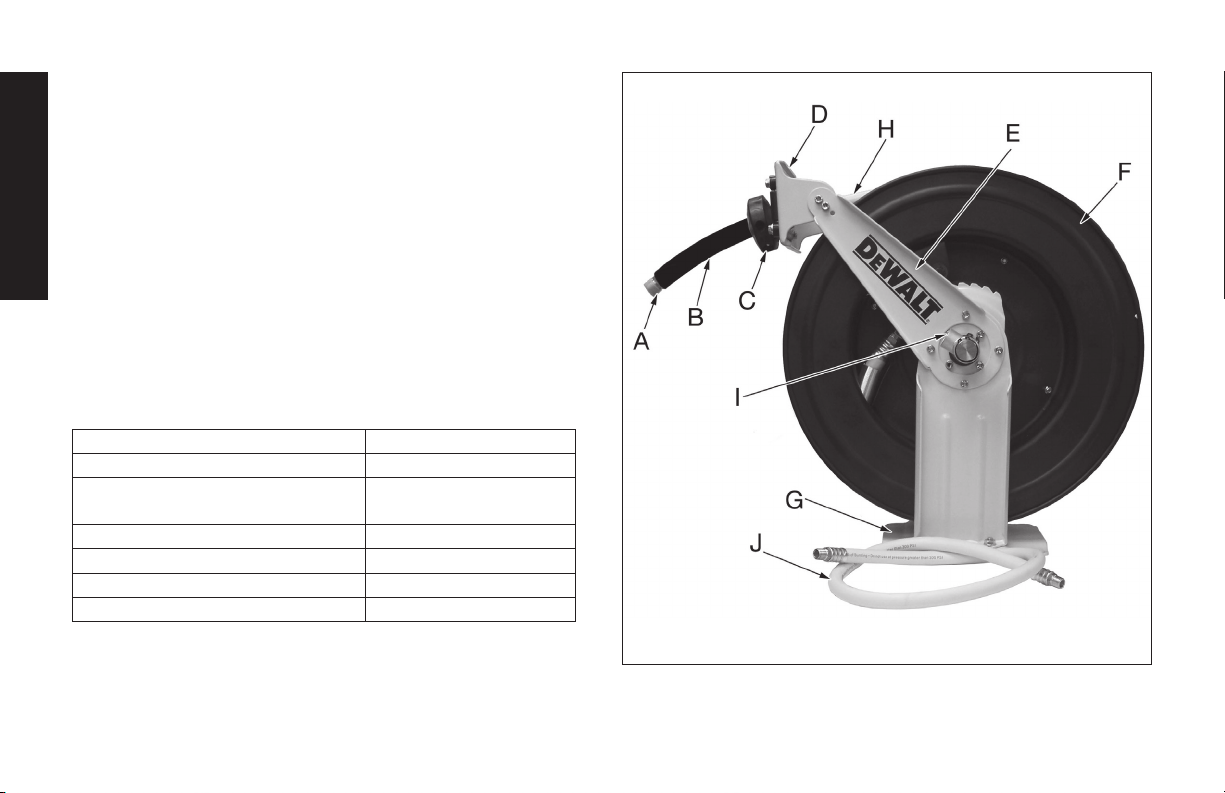
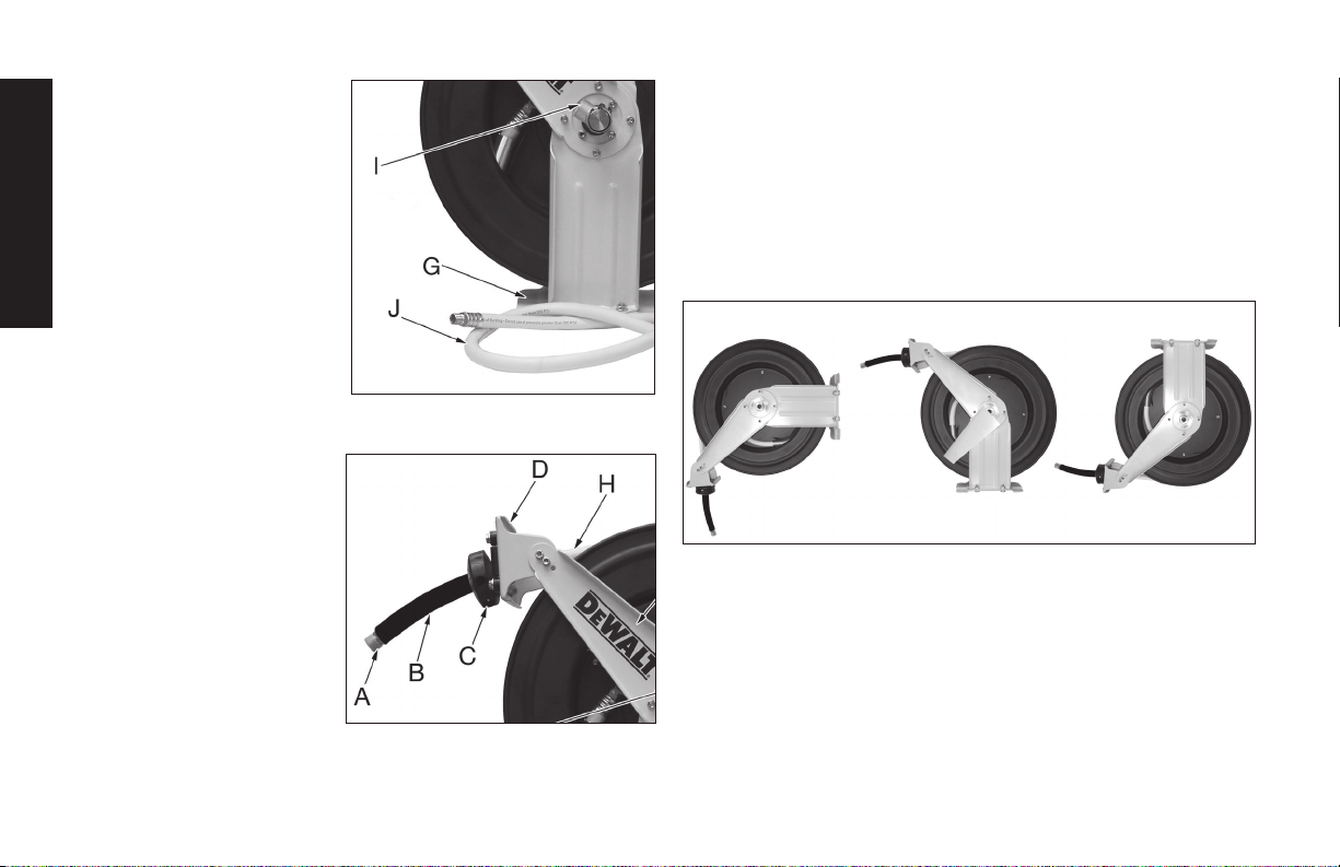
DXCM024-0344 Air Hose Reel
A. Air line outlet (to air tool/accessory)
B. Hose bend restrictor
C. Ball stop
D. Hose guide roller bracket
E. Hose guide arm
English
F. Hose reel drum
G. Mounting bracket
H. Air hose
I. Air line inlet swivel connector (from compressor)
J. Lead-in air hose
Specications
MODEL DXCM024-0344
NET WEIGHT 46.3 lbs. (21 kg)
AIR INLET SIZE 1/2" NPT (12,7 mm)
(female/hembra/femelle)
HOSE TYPE Rubber
AIR HOSE SIZE 1/2" (12,7 mm)
MAX. AIR PRESSURE 250 PSI (1,724 kPa)
AIR HOSE LENGTH 50' (15,2 m)
FIG. 1
2
Page 3
Denitions: Safety Guidelines
The definitions below describe the level of severity
for each signal word. Please read the manual and pay attention to these symbols.
DANGER: Indicates an imminently hazardous situation
which, if not avoided, will result in death or serious injury.
WARNING: Indicates a potentially hazardous situation
which, if not avoided, could result in death or serious injury.
CAUTION: Indicates a potentially hazardous situation
which, if not avoided, may result in minor or moderate
injury.
CAUTION: Used without the safety alert symbol
indicates a potentially hazardous situation which,
if not avoided, may result in property damage.
IF YOU HAVE ANY QUESTIONS OR COMMENTS ABOUT
THIS OR ANY D
1-800-4-D
EWALT (1-800-433-9258)
e
WALT TOOL, CALL US TOLL FREE AT:
Important Safety Instructions
WARNING: Some dust created by power sanding, sawing,
grinding, drilling, and other construction activities contains
chemicals known to the State of California to cause cancer, birth
defects or other reproductive harm. Some example of these
chemicals are:
• Lead from lead-based paints
• Crystalline silica from bricks and cement and other masonry
products
• Arsenic and chromium from chemically-treated lumber
Your risk from these exposures varies, depending on how often you
do this type of work. To reduce your exposure to these chemicals:
work in a well ventilated area, and work with approved safety
equipment, al ways wear OSHA/MSHA/NIOSH approved, properly
fit ting face mask or res pi ra tor when us ing such tools. When
using air tools, basic safety precautions should always be followed
to reduce the risk of personal injury.
WARNING: This product contains chemicals, known to the
State of California to cause cancer, and birth defects or other
reproductive harm. Wash hands after handling.
SAVE THESE INSTRUCTIONS
WARNING:
Improper operation or maintenance of this product
could result in serious injury and property
damage. Read and understand all warnings and
operating instructions before using this
equipment. When using air tools, basic safety
precautions should always be followed to reduce
the risk of personal injury.
WARNING:
Read and understand this instruction manual and tool
labels before installing, operating or servicing this tool.
Keep these instructions in a safe accessible place.
Operators and others in work area must wear ANSI Z87.1
CAN/CSA Z94.3 approved safety glasses with side shields.
Operators and others in work area must wear ear
protection.
English
3
Page 4
WARNING:
• Do Not Use oxygen or reactive gases; explosion may occur.
• Do Not Exceed air pressure of 250 PSI.
• Read all manuals included with this product carefully.
Be thoroughly familiar with the controls and the proper use
of the equipment.
• Do not exceed any pressure rating of any component
English
in the system.
• Disconnect the air tool from air supply before changing tools
or attachments and during non-operation.
• Always use attachments designed for use with air
powered tools.
• Do not use damaged or worn attachments.
• Check air hoses for weak or worn condition before each use.
Make sure all connections are secure.
• Keep all nuts, bolts and screws tight and ensure equipment is
in safe working condition.
DANGER: RISK OF EXPLOSION OR FIRE
WHAT CAN HAPPEN HOW TO PREVENT IT
• Exceeding the maximum
pressure rating of tools
accessories could cause an
explosion resulting
in serious injury.
• Use compressed air regulated to a maximum pressure
at or below the rated pressure
of any attachments.
DANGER: RISK TO BREATHING (ASPHYXIATION)
WHAT CAN HAPPEN HOW TO PREVENT IT
• Abrasive tools, such as
grinders, sanders, and
cut-off tools generate dust
and abrasive materials which
can be harmful to human
lungs and respiratory system.
CAUTION: RISK FROM NOISE
WHAT CAN HAPPEN HOW TO PREVENT IT
• Long term exposure to noise
produced from the operation
of air tools can lead to
permanent hearing loss.
• Always wear MSHA/NIOSH
approved, properly fitting face
mask or respirator when using
such tools.
• Always wear ANSI (S3.19)
hearing protection.
4
Page 5
WARNING: RISK OF INJURY
WHAT CAN HAPPEN HOW TO PREVENT IT
• Air tools can propel loose
objects or other materials
throughout the work area.
• Exceeding the pressure rating
of air hoses can cause them
to explode or fly apart, and
could result in serious injury.
• Keep work area clean and free
of clutter. Keep children and
others away from work area
during operation of the tool.
• Keep work area well lit.
•
Use compressed air regulated
to a maximum pressure at or
below the rated pressure of
any attachments.
•
Never use oxygen, carbon
dioxide or other bottled gases
as a power source for air tools.
•
Protect air lines from damage
or puncture.
•
Check air hoses for weak or
worn condition before each
use. Make sure all connections
are secure.
WARNING: RISK FROM FLYING OBJECTS
WHAT CAN HAPPEN HOW TO PREVENT IT
• Air powered equipment and
power tools are capable of
propelling materials such as
metal chips, saw dust, and
other debris at high speed,
which could result in serious
eye injury.
• Compressed air can be
hazardous. The air stream
can cause injury to soft tissue
areas such as eyes, ears, etc.
Particles or objects propelled
by the stream
can cause injury.
• Always wear ANSI Z87.1 CAN/
CSA Z94.3 approved safety
glasses with side shields.
• Never leave operating tool
unattended. Disconnect air
hose when tool is not in use.
• For additional protection use an
approved face shield in addition
to safety glasses.
SAVE THESE INSTRUCTIONS FOR FUTURE
USE
English
5
Page 6
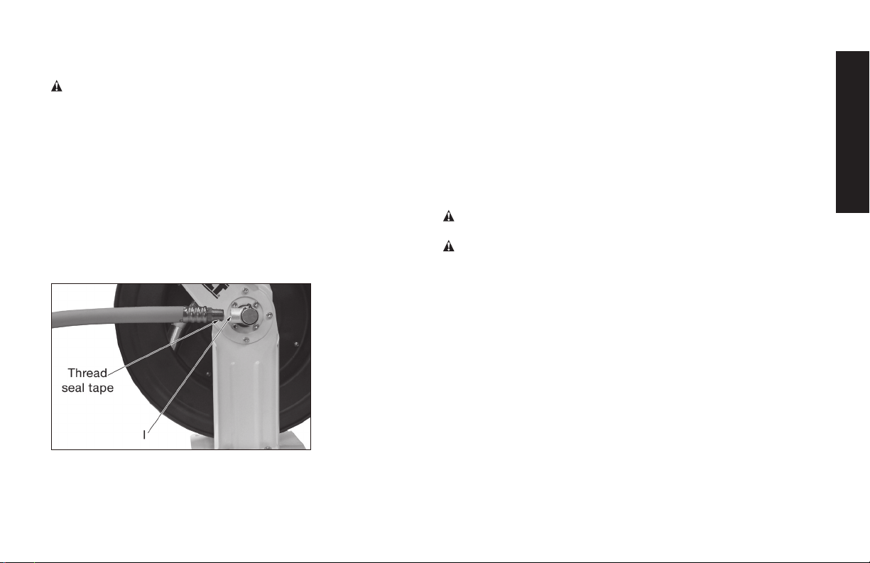
AIR LINE INLET SWIVEL
CONNECTOR
The air line inlet swivel
connector(I) is 1/2" NPT and is
located on the on the side of
the hose reel. This allows for
easy hook up to an air source.
English
MOUNTING BRACKET
The mounting bracket (G) is a
powder coated metal plate that
can be easily mounted on a
wall, ceiling or floor.
LEAD-IN AIR HOSE
The lead-in hose (J) is 1/2" x 4'
long and has a swivel connection on one end to prevent the hose
from twisting or kinking. This gets attached to the air line inlet (I).
AIR LINE OUTLET
The air line outlet (A) is 1/2"
NPT and is located on the end
of the air hose (H) for
convienient connection to air
accessories or tools.
AIR HOSE
The air hose (H) is 1/2" x 50'
and is attached to the hose
reel.
BALL STOP
The ball stop (C) is adjustable
and allows the desired length
of hose to be permanently stored outside the hose real.
HOSE BEND RESTRICTOR
The hose restrictor (B) reduces bending stress near the fitting,
preventing damage and extending the life of the hose (H).
INSTALLATION
1. Choose a mounting location that is free of electrical wiring or
other obstructions and is sturdy enough to support the weight of
the hose reel and hose as well as the force used to extend and
retract it. The hose reel can be mounted on the oor, ceiling or
wall (see Figure 2).
Figure 2
Wall Floor Ceiling
2. Use the included mounting template to mark and drill the hole
locations.
3 Mount the hose reel in the desired location. Purchase the appro-
priate fasteners at your local hardware store. Different mounting
positions require different types of hardware.
4. If an adjustment needs to made to increase or decrease the
length of hose that is outside of the hose reel, pull out the hose
slowly until it latches at the desired length. Loosen the ball stop
(C) bolts and slide the hose stop to a position close to the hose
6
Page 7
guide roller bracket (D). Retighten the ball stop bolts. Do not overtighten the bolts.
WARNING:
1) Make sure the hose reel is secure before each use.
2) Never connect to an air source that is greater than 250 PSI.
3) Inspect the air hose before each use to make sure there are
no leaks.
4) Do not wrap the hose around any parts of the body.
COMPRESSOR HOOK-UP
The hose reel includes a 1/2" x 4' lead-in hose for hooking up the
hose reel to your air source. Apply Teflon tape to the male threads
of the lead-in house and thread the non swivel end into the air hose
inlet (I). Thread and connect the other end into your air source.
Attach air tool or accessory to the air outlet of the air hose in the
hose reel.
OPERATION
Check the operation of the reel by slowly pulling out the hose. You
will hear a clicking noise.
LOCKING HOSE REEL
Pull out the hose slowly until the desire length of hose is reached,
allow it to retract after hearing a series of clicks.
UNLOCKING HOSE REEL
Pull out the hose slowly until the the clicking noise stops, allow it to
retract until the ball stop rests against the hose guide roller bracket.
DO NOT LET GO OF THE HOSE!
WARNING: Risk of Injury. Do not let go of the hose when
retracting.
WARNING: Always disconnect air tool or accessory attached to
the hose reel from air supply before making any adjustments and
changing accessories.
ADJUSTING RECOIL TENSION
1. Disconnect the air supply to the hose reel.
2 Pull out about 2 feet of air hose and lock in place (see locking
hose reel).
3. Remove the 2 piece ball stop by removing the 2 phillips head
screws, washers and nuts.
4. Feed the hose back through the hose guide roller bracket. (Note:
keep the hose reel drum locked at all times).
5. To increase tension, pull the hose around the drum one time.
6. To decrease tension, unwrap the hose one time around the
drum.
7. Push the hose back through the hose guide roller bracket
and pull out the hose from the hose reel to check the tension.
English
7
Page 8
Reinstall the ball stop.
8. Connect incoming air supply.
WARNING: The reel is under tension so use caution so that the
reel's latching mechanism does not release while adjusting the
tension.
HOSE REPLACEMENT
1. Disconnect the air supply and remove the leader hose from the
English
hose reel.
2. Remove the 2 piece ball stop by removing the 2 phillips head
screws, washers and nuts. Set aside.
3. Carefully pull all of the air hose from the hose reel until the clamp
that holds the hose to the hose reel drum is visable then make
sure the hose reel is locked
WARNING: The reel is under tension so do not turn the hose
reel drum or pull on the hose while it is locked.
4. Remove the hose clamp (located inside the hose reel drum - not
shown) and set aside.
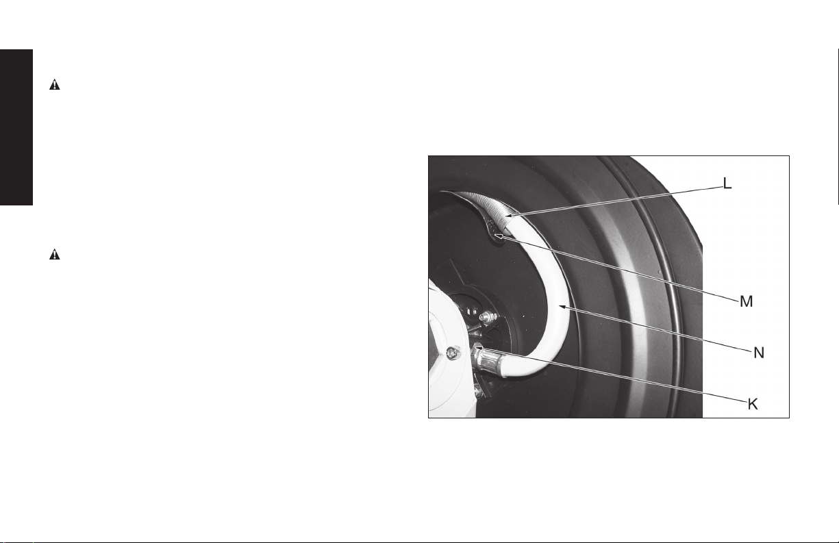
5. Carefully disconnect the hose end (K) from the side of the hose
reel and remove the old hose.
6. Remove the hose protection spring (L) from the old hose. Place
the protection spring (L) on the new hose and then feed the hose
through the hose guide roller bracket and the slot on the drum
(M).
7. Apply thread seal tape to the hose threads and connect to the
hose reel (K) then tighten.
8. Attach the hose to the inside of the drum with the hose clamp.
Make sure the hose has a wide curve (N) to it and is not kinked
before tightening the hose clamp.
9. Make sure the hose protector spring (L) is in the correct location
(reference Figure 3).
10. Pull the hose to unlock and slowly rewind the air hose. Do not let
go of the hose.
11. Re-attach the ball stop to the desired location on the hose.
12. Reconnect the lead-in hose to the hose reel and turn on the air
supply. Check all connections to make sure there are no leaks.
Figure 3
SERVICE INFORMATION
Please have the following information available for all service calls:
Model Number _____________________________________________
Date and Place of Purchase _________________________________
8
Page 9

FREE WARNING LABEL REPLACEMENT: If your warning labels
become illegible or are missing, call 1-800-4-D
replacement.
EWALT for a free
WARRANTY
ONE YEAR LIMITED WARRANTY: DEWALT Industrial Tools (the
Company) warrants that for a period of twelve (12) months from
the date of purchase, it will replace or repair, free of charge, for
the original retail purchaser only, any part or parts, manufactured
by the Company, found upon examination by the Company
or its assigned representatives, to be defective in material
or workmanship or both. All transportation charges for parts
submitted for replacement or repair under this warranty must be
borne by the original retail purchaser. This is the exclusive remedy
under this warranty.
Failure by the original retail purchaser to install, maintain and
operate said equipment in accordance with good industry
practices, or failure to comply with the specific recommendations
of the Company set forth in the owner’s manual, shall render
this warranty null and void. The Company shall not be liable for
any repairs, replacements, or adjustments to the equipment
or any costs for labor performed by the purchaser without the
Company’s prior written approval. The effects of corrosion,
erosion and normal wear and tear are specifically excluded from
this warranty.
THE COMPANY MAKES NO OTHER WARRANTY OR
REPRESENTATION OF ANY KIND WHATSOEVER,
EXPRESSED OR IMPLIED EXCEPT THAT OF TITLE. ALL
IMPLIED WARRANTIES, INCLUDING ANY WARRANTY
OF MERCHANTABILITY AND FITNESS FOR PARTICULAR
PURPOSE ARE HEREBY DISCLAIMED. LIABILITY FOR
CONSEQUENTIAL AND INCIDENTAL DAMAGES UNDER ANY
AND ALL WARRANTIES, OTHER CONTRACTS, NEGLIGENCE,
OR OTHER SORTS IS EXCLUDED TO THE EXTENT
EXCLUSION IS PERMITTED BY LAW.
Notwithstanding the above, any legal claim against the Company
shall be barred if legal action thereon is not commenced
within twenty-four (24) months from the date of purchase or
delivery whichever occurs last. This warranty constitutes the
entire agreement between the Company and the original retail
purchaser and no representative or agent is authorized to alter
the terms of same without expressed written consent of the
Company.
English
9
Page 10

DXCM024-0344 Enrouleur de tuyaux
pneumatique
A. Sortie d'air (vers outil/accessoire pneumatique)
B. Limiteur de courbure
C. Butée sphérique
D. Support cylindrique de guide tuyau
E. Bras de guide tuyau
F. Tambour d'enrouleur de tuyaux
G. Support de fixation
H. Tuyau pneumatique
I. Raccord pivotant de l'admission d'air (depuis le compresseur)
J. Tuyau pneumatique d'alimentation
Spécications
MODÈLE DXCM024-0344
POIDS NET 46.3 lbs. (21 kg)
Français
ADMISSION D'AIR 1/2" NPT (12,7 mm)
(female/hembra/femelle)
TYPE DE TUYAU PNEUMATIQUE Rubber
TAILLE DU TUYAU
PNEUMATIQUE
PRESSION OPÉRATIONNELLE
MAXIMALE DU TUYAU
LONGUEUR DU TUYAU
PNEUMATIQUE
1/2" (12,7 mm)
250 PSI (1,724 kPa)
50' (15,2 m)
FIG. 1
10
Page 11

Dénitions : lignes directrices en matière
de sécurité
Les définitions ci-dessous décrivent le niveau de gravité pour
chaque symbole. Veuillez lire le mode d’emploi et porter une
attention particulière à ces symboles.
DANGER : Indique une situation dangereuse imminente
qui, si elle n’est pas évitée, causera la mort ou des blessures
graves.
AVERTISSEMENT :
dangereuse qui, si elle n’est pas évitée, pourrait se solder par
un décès ou des blessures graves.
ATTENTION : Indique une situation potentiellement
dangereuse qui, si elle n’est pas évitée pourrait se solder par
des blessures mineures ou modérées.
AVIS : Indique une pratique ne posant aucun risque de
dommages corporels mais qui par contre, si rien n’est fait
pour l’éviter, pourrait poser des risques de dommages
matériels.
ISI VOUS AVEZ DES QUESTIONS OU DES COMMENTAIRES SUR
CE PRODUIT OU TOUT AUTRE OUTIL D
GRATUITEMENT AU: 1-800-4-D
Indique une situation potentiellement
e
WALT APPELEZ-NOUS
EWALT (1-800-433-9258)
Consignes de sécurité importantes
AVERTISSEMENT: certaines poussières qui se forment lors
du ponçage mécanique, du sciage, de l'affûtage, du fraisage
ou d'autres activités de construction contiennent des produits
chimiques qui, selon l'État de Californie, peuvent provoquer des
cancers, des malformations à la naissance ou d'autres problèmes
de reproduction. Voici certains exemples de ces produits
chimiques:
• Le plomb provenant des peintures à base de plomb
• La silice cristalline provenant des briques, du ciment et
d'autres produits de maçonnerie
• L'arsenic et le chrome provenant du bois traité chimiquement
Le risque d'exposition dépend de la fréquence à laquelle vous
effectuez ce genre de tâches. Afin de réduire l'exposition à ces
produits chimiques: travaillez dans un environnement ventilé en
portant un équipement de sécurité adéquat, et portez toujours
un équipement approuvé par les institutions OSHA/MSHA/
NIOSH, ainsi qu'un masque facial ou un respirateur à votre taille
lorsque vous utilisez ces outils. Lorsque vous utilisez des outils
pneumatiques, respectez en permanence les mesures de sécurité
élémentaires afin de réduire le risque de dommages corporels.
AVERTISSEMENT: ce produit contient des produits chimiques
qui, selon l'État de Californie, peuvent provoquer des cancers,
des malformations à la naissance ou d'autres problèmes de
reproduction. Se laver les mains après manipulation.
CONSERVEZ CES INSTRUCTIONS
AVERTISSEMENT
Toute mauvaise utilisation ou maintenance de ce
produit peut entraîner des blessures graves et des
dégâts matériels. Lisez attentivement les
avertissements et le mode d'emploi avant d'utiliser
cet équipement. Lorsque vous utilisez des outils
pneumatiques, respectez en permanence les
mesures de sécurité élémentaires afin de réduire
le risque de dommages corporels.
VERTISSEMENT
Lisez attentivement ce mode d'emploi et les étiquettes
des outils avant d'installer, d'utiliser ou d'entretenir cet
enrouleur de tuyaux. Conservez ces instructions dans un
Français
11
Page 12

endroit sûr et accessible.
Les opérateurs et autres personnes présentes dans la
zone de travail doivent porter des lunettes de sécurité
conformes à l'ANSI Z87.1 CAN/CSA Z94.3 avec
protections latérales.
Les opérateurs et autres personnes présentes dans la
zone de travail doivent porter des protections auditives.
AVERTISSEMENT:
• N'utilisez jamais d'oxygène ou de gaz réactifs. Cela pourrait
provoquer une explosion.
• La pression de l'air ne doit jamais dépasser les 250 psi (17 bar).
• Lisez attentivement tous les manuels inclus avec ce produit.
Familiarisez-vous avec les commandes et apprenez à utiliser
cet équipement correctement.
• Ne dépassez jamais la pression nominale d'un composant du
système.
Français
• Déconnectez l'outil pneumatique de l'alimentation en air avant
de changer les outils ou les accessoires et lorsqu'il est à l'arrêt.
• Utilisez toujours des accessoires conçus pour être utilisés avec
des outils pneumatiques.
• N'utilisez jamais d'accessoires usés ou endommagés.
• Contrôlez les tuyaux pneumatiques avant chaque utilisation afin
de vous assurer qu'ils ne sont ni usés ni endommagés.
Assurez-vous que tous les raccordements sont sécurisés.
• Assurez-vous que les écrous, les boulons et les vis sont bien
serré(e)s et que l'équipement fonctionne dans des conditions
de travail sûres.
DANGER: RISQUE D'EXPLOSION OU D'INCENDIE
CE QUI PEUT SE PRODUIRE COMMENT L'EMPÊCHER
• Dépasser la pression nominale maximale des accessoires peut provoquer une
explosion et entraîner des
blessures graves.
DANGER: RISQUE DE DIFFICULTÉS RESPIRATOIRES
CE QUI PEUT SE PRODUIRE COMMENT L'EMPÊCHER
• Des outils abrasifs, comme
des meuleuses, des
ponceuses et des outils de
coupe peuvent produire de
la poussière et des matériaux
abrasifs qui peuvent être
dangereux pour les poumons
et le système respiratoire.
ATTENTION: RISQUE ASSOCIÉ AU BRUIT
CE QUI PEUT SE PRODUIRE COMMENT L'EMPÊCHER
• Utiliser de l'air comprimé
régulé à une pression maximale inférieure ou égale à
la pression nominale
de chaque accessoire.
(ASPHYXIE)
• Portez toujours un équipement
approuvé par la MSHA/
NIOSH, ainsi qu'un masque
facial ou un respirateur à votre
taille lorsque vous utilisez ces
outils.
12
Page 13

• Une exposition prolongée
aux bruits produits par des
outils pneumatiques en
fonctionnement peut entraîner
une perte de l'audition
permanente.
AVERTISSEMENT: RISQUE DE PROJECTION
CE QUI PEUT SE PRODUIRE COMMENT L'EMPÊCHER
• Les équipements et outils
pneumatiques peuvent
propulser des matériaux
comme des copeaux
métalliques, de la sciure et
d'autres débris à une vitesse
élevée, ce qui peut provoquer
des graves blessures
oculaires.
• L'air comprimé peut s'avérer
dangereux. Le flux d'air peut
provoquer des blessures
au niveau des tissus mous
comme les yeux, les oreilles,
etc. Les particules et les
objets propulsés par le flux
d'air peuvent entraîner des
blessures.
• Portez toujours des protections
auditives conformes à l'ANSI
(S3.19).
• Portez toujours des lunettes
de sécurité conformes à l'ANSI
Z87.1 CAN/CSA Z94.3 avec
protections latérales.
• Ne laissez jamais un outil
en fonctionnement sans
surveillance. Déconnectez le
tuyau pneumatique lorsque
l'outil est à l'arrêt.
• Pour être mieux protégé,
utilisez un masque de
protection approuvé en plus
des lunettes de sécurité.
ATTENTION: RISQUÉ DE BLESSURE
CE QUI PEUT SE PRODUIRE COMMENT L'EMPÊCHER
• Les outils électriques peuvent
lancer des matériaux dans
toute la zone de travail.
• Dépasser la pression
maximale nominale des
accessoires de l’outil peut
causer une explosion
causant des blessures
graves.
• Keep work area clean and free
Conserver la zone de travail
propre et en bon ordre. Éloigner
les enfants et autrui de la zone
de travail durant l’utilisation de
l’outil.
• Conserver les lieux bien
illuminés.
•
Utiliser de l’air comprimé réglé
à une pression maximale près
ou au-dessous de la pression
nominale des accessoires.
•
Ne jamais utiliser de gaz
oxygène, de dioxyde de
carbone ou autres gaz en
bouteille comme source
d’énergie pour les outils
pneumatiques.
•
Protégez les conduits d’air des
dommages et des perforations.
•
Vérifiez les boyaux d’air en cas
d’usure ou de détérioration
avant chaque emploi.
S’assurer que tous les
raccords sont bien branchés.
Français
CONSERVEZ CES INSTRUCTIONS POUR UNE FUTURE
UTILISATION
13
Page 14

FONCTIONNALITÉS
RACCORD PIVOTANT DE L'ADMISSION D'AIR
Le raccord pivotant de
l'admission d'air (I) mesure 1/2"
(1,2 cm) NPT et est situé sur le
côté de l'enrouleur de tuyaux.
Cela permet de le brancher
rapidement à une source
d'alimentation en air.
SUPPORT DE FIXATION
Le support de fixation (G) est
une plaque de métal laqué qui
peut être facilement fixée sur un
mur, au plafond ou au sol.
TUYAU PNEUMATIQUE
D'ALIMENTATION
Le tuyau d'alimentation (J)
Français
mesure 1/2" (1,2 cm) x 4' (1,2
m) de long et est équipé d'un
raccord pivotant sur l'une de
ses extrémités afin d'éviter que
le tuyau ne se torde ou ne
s'emmêle. Il se connecte à
l'admission d'air (I).
SORTIE D'AIR
La sortie d'air (A) mesure
1/2" (1,2 cm) NPT et est
située à l'extrémité du tuyau
pneumatique (H) pour être facilement connectée aux outils et
accessoires pneumatiques.
TUYAU PNEUMATIQUE
Le tuyau pneumatique (H) mesure 1/2" (1,2 cm) x 50' (15 m) et est
attaché à l'enrouleur de tuyaux.
BUTÉE SPHÉRIQUE
La butée sphérique (C) est réglable et permet de sortir la longueur
de tuyau souhaitée de façon permanente.
LIMITEUR DE COURBURE
Le limiteur de courbure (B) réduit la tension provoquée par le
pliage du tuyau au niveau du raccord, ce qui permet d'éviter les
dommages et de prolonger la durée de vie du tuyau (H).
INSTALLATION
1. Choisissez un emplacement de xation ne présentant aucun
câble électrique ou autre obstacle, et sufsamment robuste pour
supporter le poids de l'enrouleur et du tuyau, ainsi que la force
exercée lorsqu'il est étendu et rétracté. L'enrouleur de tuyaux
peut être xé sur le sol, au plafond ou sur un mur (voir Figure 2).
Figure 2
Mur Sol Plafond
2. Utilisez le gabarit de xation inclus an de marquer
l'emplacement des trous et de percer à ces endroits.
3 Fixez l'enrouleur de tuyaux à l'emplacement souhaité. Achetez les
éléments de xation adéquats dans votre magasin de bricolage.
14
Page 15

Les différentes positions de xation requièrent différents types
d'équipements.
4. Si vous souhaitez augmenter ou réduire la longueur du tuyau
située à l'extérieur de l'enrouleur, tirez doucement sur le tuyau
jusqu'à ce qu'il soit verrouillé à la longueur souhaitée. Desserrez
les boulons de la butée sphérique (C) et faites-la glisser pour la
rapprocher du support cylindrique du guide tuyau (D). Resserrez
les boulons de la butée sphérique. Ne serrez pas les boulons de
manière excessive.
AVERTISSEMENT:
1) Assurez-vous que l'enrouleur est bien fixé avant chaque
utilisation.
2) Ne le connectez jamais à une source d'alimentation en air dont
la pression est supérieure à 250 psi (17 bar).
3) Inspectez le tuyau pneumatique avant chaque utilisation afin
de vous assurer qu'il ne présente aucune fuite.
4) N'enroulez jamais le tuyau autour d'une partie de votre corps.
BRANCHEMENT DU COMPRESSEUR
L'enrouleur de tuyaux est
accompagné d'un tuyau
d'alimentation 1/2" (1,2
cm) x 4' (1,2 m) pour le
connecter à une source
d'alimentation en air.
Appliquez le ruban de
téflon aux filetages mâles
du tuyau d'alimentation,
puis insérez l'extrémité
non pivotante dans
l'admission d'air du tuyau
(I). Connectez l'autre
extrémité à votre source d'alimentation en air. Attachez l'outil ou
accessoire pneumatique à la sortie d'air du tuyau pneumatique de
l'enrouleur.
UTILISATION
Assurez-vous du bon fonctionnement de l'enrouleur en tirant
doucement sur le tuyau. Vous entendrez un cliquètement.
VERROUILLER L'ENROULEUR
Tirez doucement sur le tuyau jusqu'à atteindre la longueur souhaitée,
puis laissez-le se rétracter après la série de cliquètements.
DÉVERROUILLER L'ENROULEUR
Tirez doucement sur le tuyau jusqu'à ce que le cliquètement s'arrête,
puis laissez-le se rétracter jusqu'à ce que la butée sphérique soit
bloquée par le support cylindrique du guide tuyau. NE LÂCHEZ
JAMAIS LE TUYAU!
AVERTISSEMENT: risque de blessure. Ne lâchez jamais le
tuyau lorsqu'il se rétracte.
AVERTISSEMENT: déconnectez toujours l'outil ou accessoire
pneumatique attaché à l'enrouleur de l'alimentation en air avant
d'effectuer des réglages ou de changer d'accessoire.
RÉGLER LA TENSION DE RECUL
1. Déconnectez l'alimentation en air de l'enrouleur de tuyaux.
2 Tirez sur le tuyau pneumatique sur environ 50 centimètres, puis
verrouillez-le (voir Verrouiller l'enrouleur).
3. Retirez la butée sphérique en deux parties en retirant les 2 vis
cruciformes, les rondelles et les écrous.
4. Ramenez le tuyau vers l'arrière en le faisant passer par le support cylindrique du guide tuyau (remarque: le tambour de
l'enrouleur doit toujours rester verrouillé).
5. Pour augmenter la tension, enroulez le tuyau une fois autour du
Français
15
Page 16

tambour.
6. Pour diminuer la tension, déroulez le tuyau une fois.
7. Faites repasser le tuyau par le support cylindrique du guide
tuyau, puis tirez dessus pour vérier la tension. Réinstallez la
butée sphérique.
8. Connectez l'alimentation en air.
AVERTISSEMENT: étant donné que l'enrouleur est tendu,
soyez prudent et assurez-vous que le mécanisme de verrouillage
ne se relâche pas pendant que vous réglez la tension.
REMPLACER LE TUYAU
1. Déconnectez l'alimentation en air et retirez le tuyau d'alimentation
de l'enrouleur.
2. Retirez la butée sphérique en deux parties en retirant les 2 vis
cruciformes, les rondelles et les écrous. Mettez ces éléments de
côté.
3. Tirez délicatement sur le tuyau pneumatique pour le sortir complètement de l'enrouleur jusqu'à ce que le collier qui relie le tuyau
Français
au tambour de l'enrouleur soit visible, puis assurez-vous que
l'enrouleur est bien verrouillé.
AVERTISSEMENT: étant donné que l'enrouleur est sous ten-
sion, assurez-vous de ne pas tourner le tambour de l'enrouleur
ou de ne pas tirer sur le tuyau tant qu'il est verrouillé.
4. Retirez le collier du tuyau (situé à l'intérieur du tambour de
l'enrouleur - non illustré) et mettez-le de côté.
5. Déconnectez délicatement l'extrémité du tuyau (K) du côté de
l'enrouleur, puis retirez le tuyau à remplacer.
6. Retirez le ressort de protection (L) du tuyau à remplacer. Installez
le ressort de protection (L) sur le nouveau tuyau et faites passer
le tuyau par le support cylindrique du guide tuyau, puis dans
l'encoche située dans le tambour (M).
7. Appliquez un joint d'étanchéité sur les letages du tuyau, connectez le tuyau à l'enrouleur (K), puis serrez-le.
8. Attachez le tuyau à l'intérieur du tambour à l'aide du collier de
serrage. Avant de serrer le collier, faites en sorte que le tuyau ait
une courbe large (N) et qu'il ne présente aucun nœud.
9. Assurez-vous que le ressort de protection du tuyau (L) a été placé
au bon endroit (voir Figure 3).
10. Tirez sur le tuyau pneumatique pour déverrouiller l'enrouleur, puis
rembobinez-le lentement. Ne lâchez jamais le tuyau.
11. Attachez de nouveau la butée sphérique à l'emplacement souhaité sur le tuyau.
12. Reconnectez le tuyau d'alimentation à l'enrouleur, puis activez
l'alimentation en air. Inspectez tous les raccords pour vérier
qu'ils ne présentent aucune fuite.
Figure 3
RENSEIGNEMENTS POUR L'ENTRETIEN
Merci de communiquer les renseignements suivants lors de chaque
16
Page 17

appel au service clientèle:
Numéro du modèle _______________________________________
Date et lieu d'achat _________________________________
REMPLACEMENT GRATUIT DES ÉTIQUETTES
D'AVERTISSEMENT: si vous perdez vos étiquettes
d'avertissement ou qu'elles deviennent illisibles, appelez le
1-800-4-D
e
WA LT pour les remplacer gratuitement.
GARANTIE
GARANTIE LIMITÉE D'UN AN: DeWA LT Industrial Tools (la
Société) s'engage, pendant une période de douze (12) mois
à compter de la date d'achat, à remplacer ou à réparer
gratuitement, pour l'acheteur d'origine uniquement, toute pièce
fabriquée par la Société qui, après examen de la Société ou
de ses représentants légaux, s'avèrerait défectueuse en raison
d'un vice de matière, de fabrication, ou les deux. Tous les frais
de transport induits par un remplacement ou une réparation de
pièce en vertu de la présente garantie devront être pris en charge
par l'acheteur d'origine. Il s'agit du seul recours possible en vertu
de la présente garantie.
L'incapacité de l'acheteur d'origine à installer, entretenir et
utiliser ledit équipement conformément aux bonnes pratiques de
l'industrie, ou son incapacité à respecter les recommandations
spécifiques de la Société établies dans le manuel du propriétaire
annulera les termes de la présente garantie. La Société rejette
toute responsabilité pour les réparations, remplacements ou
ajustements à l’équipement ou pour tous coûts reliés au travail
effectué sur l’équipement par l’acheteur sans l’autorisation
préalable écrite de la Société. La corrosion, l'érosion, ainsi que
l'usure et les fissures normales sont expressément exclues de la
présente garantie.
LA SOCIÉTÉ N’OFFRE AUCUNE AUTRE GARANTIE,
NI REPRÉSENTATION DE QUELQUE SORTE QUE CE
SOIT, EXPRESSE OU IMPLICITE, EXCEPTION FAITE DE
LA PROPRIÉTÉ. TOUTES LES GARANTIES IMPLICITES
SONT REJETÉES PAR LA PRÉSENTE, EN PARTICULIER
TOUTES LES GARANTIES DE COMMERCIALISATION
ET D’ADÉQUATION À UN USAGE PARTICULIER. TOUTE
RESPONSABILITÉ POUR DES DOMMAGES INDIRECTS EN
VERTU D’UNE OU DE TOUTES LES GARANTIES, D’AUTRES
CONTRATS, DE LA NÉGLIGENCE OU D’AUTRES DÉLITS
CIVILS EST EXCLUE CONFORMÉMENT AUX CLAUSES
D’EXCLUSION AUTORISÉES PAR LA LOI.
Nonobstant ce qui précède, toute revendication légale
à l'encontre de la Société sera impossible si l'action légale
en question débute plus de vingt-quatre (24) mois après la
date d'achat ou de livraison, selon ce qui survient en dernier.
La présente garantie constitue l'intégralité de l'accord entre
la Société et l'acheteur d'origine, et aucun représentant ou
agent n'est autorisé à modifier les termes de la présente sans
l'autorisation écrite expresse de la Société.
Français
17
Page 18

Carrete de manguera de aire DXCM024-0344
A. Salida de la línea de aire (hacia la herramienta/el accesorio de
aire)
B. Limitador de flexión de la manguera
C. Retén de bola
D. Soporte del rodillo guía de la manguera
E. Brazo guía de la manguera
F. Tambor del carrete de manguera
G. Soporte de montaje
H. Manguera de aire
I. Conector pivotante de entrada de línea de aire (del compresor)
J. Manguera de aire de entrada
Especicaciones
MODELO DXCM024-0344
PESO NETO 46.3 lbs. (21 kg)
ENTRADA DE AIRE 1/2" NPT (12,7 mm)
(female/hembra/femelle)
TIPO DE MANGUERA DE AIRE Rubber
TAMAÑO DE LA MANGUERA DE
AIRE
PRESIÓN MÁXIMA DE
OPERACIÓN DE LA MANGUERA
LONGITUD DE LA MANGUERA
Español
DE AIRE
1/2" (12,7 mm)
250 PSI (1,724 kPa)
50' (15,2 m)
FIG. 1
18
Page 19

Definiciones: Normas de seguridad
Las siguientes definiciones describen el nivel de gravedad de
cada advertencia. Lea el manual y preste atención a estos
símbolos.
PELIGRO: Indica una situación de peligro inminente que,
si no se evita, provocará la muerte o lesiones graves.
ADVERTENCIA: Indica una situación de peligro
potencial que, si no se evita, podría provocar la muerte o
lesiones graves.
ATENCIÓN: Indica una situación de peligro potencial
que, si no se evita, puede provocar lesiones leves o
moderadas.
AVISO: Se refiere a una práctica no relacionada a lesiones
corporales que de no evitarse puede resultar en daños a
la propiedad.
SI TIENE PREGUNTAS O COMENTARIOS ACERCA DE ESTA O
DE CUALQUIER OTRA HERRAMIENTA D
NÚMERO GRATUITO: 1-800-4-D
e
WALT (1-800-433-9258).
e
WALT, LLÁMENOS AL
Instrucciones de seguridad importantes
ADVERTENCIA:Algunos polvos que se producen al lijar,
cortar, esmerilar o perforar con herramientas eléctricas, así como
en otras actividades de construcción, contienen químicos que
el estado de California sabe que provocan cáncer, defectos
congénitos u otros daños al aparato reproductor. Algunos
ejemplos de estos químicos son:
• plomo en las pinturas a base de plomo;
• sílice cristalino en los ladrillos, el cemento y en otros
productos de mampostería;
• arsénico y cromo en la madera tratada con químicos.
El riesgo de estas exposiciones varía en función de la
frecuencia con la que se realice este tipo de trabajo. Para
reducir la exposición a estos químicos, cuando utilice dichas
herramientas: trabaje en un área bien ventilada, utilice equipo
de seguridad aprobado y use siempre una máscara o un
respirador que se ajusten correctamente y que estén aprobados
por la Administración de Seguridad y Salud Ocupacional
(Occupational Safety and Health Administration, OSHA)/la
Administración de Seguridad y Salud de Minas (Mine Safety
and Health Administration, MSHA)/el Instituto Nacional
de Seguridad y Salud Ocupacional (National Institute for
Occupational Safety and Health, NIOSH). Al usar herramientas
de aire, siempre se deben seguir precauciones de seguridad
básicas para reducir el riesgo de sufrir lesiones personales.
ADVERTENCIA: Este producto contiene químicos que según
el estado de California provocan cáncer, defectos congénitos u
otros daños al aparato reproductor. Lávese las manos antes de
manipular.
CONSERVE ESTAS INSTRUCCIONES
ADVERTENCIA:
La operación o el mantenimiento incorrectos de
este producto podrían provocar lesiones graves y
daños materiales. Lea todas las advertencias e
instrucciones de operación antes de usar este
equipo, y asegúrese de entenderlas. Al usar
herramientas de aire, siempre se deben seguir
precauciones de seguridad básicas para reducir el
riesgo de sufrir lesiones personales.
Español
19
Page 20

ADVERTENCIA:
Antes de instalar, operar o dar servicio a este carrete de
manguera, lea este manual de instrucciones y las
etiquetas de la herramienta, y asegúrese de entenderlas.
Mantenga estas instrucciones en un lugar seguro y
accesible.
Los operadores y el personal presentes en el área de
trabajo deben usar gafas de seguridad, con protectores
laterales, aprobadas según los estándares ANSI Z87.1 y
CAN/CSA Z94.3.
Los operadores y el personal presentes en el área de
trabajo deben usar protección para los ojos.
ADVERTENCIA:
• No use oxígeno ni gases reactivos; se podría producir una
explosión.
• No supere una presión de aire de 250 PSI.
• Lea detenidamente todos los manuales que se incluyen con
este producto. Familiarícese bien con los controles y el uso
correcto del equipo.
• No supere las capacidades nominales de presión de los
componentes del sistema.
• Desconecte la herramienta de aire del suministro de aire antes
de cambiar herramientas o accesorios, y cuando no se esté
usando.
• Siempre use accesorios diseñados para usarse con
herramientas neumáticas.
• No use accesorios dañados o desgastados.
Español
• Revise las mangueras de aire en busca de condiciones de
desgaste o debilitamiento antes de cada uso. Confirme que
todas las conexiones estén bien aseguradas.
• Mantenga todas las tuercas, los pernos y los tornillos
apretados y asegúrese de que el equipo esté en condiciones
de funcionamiento seguro.
PELIGRO: RIESGO DE EXPLOSIÓN O INCENDIO
LO QUE PUEDE OCURRIR CÓMO EVITARLO
• Superar la capacidad
nominal de presión máxima
de los accesorios de herramientas podría provocar
una explosión que ocasione
lesiones graves.
PELIGRO: RIESGO PARA LA RESPIRACIÓN (ASFIXIA)
LO QUE PUEDE OCURRIR CÓMO EVITARLO
• Las herramientas abrasivas,
como las esmeriladoras, las
lijadoras y las herramientas
de corte producen polvo y
materiales abrasivos que
pueden ser dañinos para
los pulmones y el sistema
respiratorio humano.
PRECAUCIÓN: RIESGO POR RUIDO
• Use aire comprimido
regulado a una presión
máxima igual o menor
a la presión nominal
de los accesorios.
• Cuando utilice dichas
herramientas, use siempre
una máscara o un respirador
que se ajusten correctamente
y que estén aprobados por la
MSHA/el NIOSH.
20
Page 21

LO QUE PUEDE OCURRIR CÓMO EVITARLO
• La exposición al ruido a largo
plazo que se produce con la
operación de herramientas de
aire puede provocar pérdida
auditiva permanente.
ADVERTENCIA: RIESGO DE OBJETOS QUE SALEN
LO QUE PUEDE OCURRIR CÓMO EVITARLO
• El equipo neumático y las
herramientas eléctricas
pueden lanzar materiales
como virutas metálicas,
serrín y otros residuos a alta
velocidad, lo que podría
provocar lesiones oculares
graves.
• El aire comprimido puede
ser peligroso. El chorro de
aire puede provocar lesiones
en áreas de tejido blando
como los ojos, los oídos, etc.
Las partículas o los objetos
que lanza el chorro pueden
provocar lesiones.
• Siempre use protección
auditiva según los estándares
ANSI (S3.19).
DISPARADOS
• Siempre use gafas de
seguridad, con protectores
laterales, aprobadas según los
estándares ANSI Z87.1 y CAN/
CSA Z94.3.
• Nunca deje herramienta
funcionando sin supervisión.
Desconecte la manguera de
aire cuando no se esté usando
la herramienta.
• Para mayor protección, use un
protector facial además de las
gafas de seguridad.
ADVERTENCIA: RIESGO DE RIESGO DE LESIÓN
LO QUE PUEDE OCURRIR CÓMO EVITARLO
• Las herramientas neumáticas
pueden despedir objetos flojos
u otros materiales en el área
de trabajo.
• El exceder la clasificación
máxima presión de la
herramienta o de los
accesorios podrá causar una
explosión resultando en
lesiones graves.
• Mantenga el área de trabajo
limpia y libre de obstrucciones.
Mantenga a los niños y otros
alejados del área de trabajo
mientras opera la herramienta
• Mantenga el área bien
alumbrada.
•
Use aire comprimido regulado
a la presión máxima o por
debajo de la clasificación de
presión de cualquier accesorio.
•
Nunca use oxígeno, dióxido de
carbono u otro gas
embotellado como fuente
deenergía para las
herramientas neumáticas.
•
Proteja la manguera de aire de
daños y perforaciones.
•
Revise las mangueras de aire
para ver si están desgastadas
o débiles antes de cada uso.
Asegúrese de que todas las
conexiones estén seguras.
CONSERVE ESTAS INSTRUCCIONES PARA
USARLAS EN EL FUTURO
Español
21
Page 22

CARACTERÍSTICAS
CONECTOR PIVOTANTE DE ENTRADA DE LÍNEA DE AIRE
El conector pivotante de
entrada de línea de aire (I) tiene
rosca NPT de 1/2” y se encuentra
en el lado del carrete de
manguera. Esto permite
conectarlo fácilmente a una
fuente de aire.
SOPORTE DE MONTAJE
El soporte de montaje (G) es
una placa metálica con pintura
en polvo que se puede montar
fácilmente en una pared, un techo
o un piso.
MANGUERA DE AIRE DE
ENTRADA
La manguera de entrada (J) es
de 1/2” x 4 ft de largo y tiene una
conexión pivotante en un extremo
para evitar que la manguera se
retuerza. Se conecta a la entrada
de línea de aire (I).
SALIDA DE LA LÍNEA DE AIRE
La salida de la línea de aire (A)
tiene rosca NPT de 1/2” y se
encuentra en el extremo de la
manguera de aire (H) para una
Español
conexión conveniente de los accesorios o las herramientas de aire.
MANGUERA DE AIRE
La manguera de aire (H) es de 1/2” x 50 ft y está conectada al
carrete de manguera.
RETÉN DE BOLA
El retén de bola (C) es ajustable y permite guardar de forma
permanente la longitud de manguera deseada fuera del carrete de
manguera.
LIMITADOR DE FLEXIÓN DE LA MANGUERA
El limitador de la manguera (B) reduce la tensión de flexión cerca
del accesorio, lo que previene los daños y alarga la vida útil de la
manguera (H).
INSTALACIÓN
1. Elija un lugar de montaje que esté libre de cableado eléctrico
u otras obstrucciones y que sea lo suficientemente resistente para soportar el peso del carrete de manguera y de la
manguera, así como la fuerza que se usa para desenrollar la
manguera y retraerla. El carrete de manguera se puede montar
en el piso, el techo o la pared (vea la figura 2).
Pared Piso Techo
Figura 2
2. Use la plantilla de montaje incluida para marcar y perforar los
lugares de los orificios.
3. Monte el carrete de manguera en el lugar deseado. Compre los
sujetadores adecuados en su ferretería local. Necesitará
distintos tipos de material para cada posición de montaje.
22
Page 23

4. Si es necesario hacer un ajuste para aumentar o disminuir la
longitud de la manguera que sale del carrete de manguera, jale
la manguera lentamente hasta que se trabe a la longitud
deseada. Afloje los pernos del retén de bola (C) y deslice el retén
de la manguera hasta una posición cercana al soporte del rodillo
guía de la manguera (D). Vuelva a apretar los pernos del retén de
bola. No apriete excesivamente los pernos
ADVERTENCIA:
1) Asegúrese de que el carrete de manguera esté seguro antes
de cada uso.
2) Nunca lo conecte a una fuente de aire que tenga más de 250
PSI.
3) Inspeccione la manguera de aire antes de cada uso para
asegurarse de que no tenga fugas.
4) No enrolle la manguera en ninguna parte del cuerpo.
CONEXIÓN AL COMPRESOR
El carrete de manguera
incluye una manguera de
entrada de 1/2” x 4 ft para
conectar el carrete de
manguera a la fuente de
aire. Aplique cinta de teflón
a la rosca exterior de la
manguera de entrada y
enrosque el extremo no
pivotante en la entrada de
la manguera de aire (I). Enrosque y conecte el otro extremo a la
fuente de aire. Conecte la herramienta o el accesorio de aire a la
salida de aire de la manguera de aire en el carrete de manguera.
FUNCIONAMIENTO
Revise el funcionamiento del carrete jalando lentamente la manguera
para desenrollarla. Oirá un chasquido.
CÓMO TRABAR EL CARRETE DE MANGUERA
Jale la manguera lentamente para desenrollarla hasta alcanzar la
longitud deseada de manguera, deje que se retraiga después de
que oiga una serie de chasquidos.
CÓMO DESTRABAR EL CARRETE DE MANGUERA
Jale la manguera lentamente para desenrollarla hasta que se
detenga el ruido de chasquido, deje que se retraiga hasta que
el retén de bola descanse sobre el soporte del rodillo guía de la
manguera. ¡NO SUELTE POR COMPLETO LA MANGUERA!
ADVERTENCIA: Riesgo de lesiones. No suelte por completo
la manguera al dejar que se retraiga.
ADVERTENCIA: Siempre desconecte la herramienta o el
accesorio de aire que esté conectado al carrete de manguera del
suministro de aire antes de hacer cualquier ajuste o de cambiar
accesorios.
CÓMO AJUSTAR LA TENSIÓN DE
REBOBINADO
1. Desconecte el suministro de aire del carrete de manguera.
2. Desenrolle unos 60 cm de manguera de aire y trábela en su sitio
(consulte “Cómo trabar el carrete de manguera”).
3. Retire el retén de bola de 2 piezas: saque los 2 tornillos de cabeza Phillips, las arandelas y las tuercas.
4. Vuelva a meter la manguera por el soporte del rodillo guía de
la manguera. (Nota: Mantenga el tambor del carrete de
manguera trabado en todo momento).
5. Para aumentar la tensión, enrolle la manguera en el tambor una
vez.
23
Español
Page 24

6. Para disminuir la tensión, desenrolle la manguera del tambor una
vez.
7. Meta la manguera por el soporte del rodillo guía de la manguera
y desenrolle la manguera del carrete de manguera para vericar
la tensión. Vuelva a instalar el retén de bola.
8. Conecte el suministro de aire de entrada.
ADVERTENCIA: El carrete se encuentra bajo tensión, así que
tenga cuidado de que el mecanismo de traba del carrete no se
suelte mientras ajusta la tensión.
REEMPLAZO DE LA MANGUERA
1. Desconecte el suministro de aire y retire la manguera guía del
carrete de manguera.
2. Retire el retén de bola de 2 piezas: saque los 2 tornillos de cabeza Phillips, las arandelas y las tuercas. Colóquelo a un lado.
3. Desenrolle con cuidado toda la manguera de aire del carrete
de manguera hasta que pueda ver la abrazadera que sujeta la
manguera al tambor del carrete de manguera; luego, asegúrese
de que el carrete de manguera esté trabado.
ADVERTENCIA: El carrete está bajo tensión, así que no gire el
tambor del carrete de manguera ni jale la manguera cuando el
carrete esté trabado.
4. Retire la abrazadera de la manguera (se encuentra en el interior
del tambor del carrete de manguera, no se muestra) y colóquela
a un lado.
5. Desconecte con cuidado el extremo de la manguera (K) del lateral del carrete de manguera y retire la manguera vieja.
6. Retire el resorte de protección de la manguera (L) de la manguera
Español
vieja. Coloque el resorte de protección (L) en la nueva manguera
y luego meta la manguera por el soporte del rodillo guía de la
manguera y por la ranura del tambor (M).
7. Aplique cinta selladora de rosca a la rosca de la manguera y
conecte esta última al carrete de manguera (K) y apriétela.
8. Fije la manguera al interior del tambor con la abrazadera de
la manguera. Asegúrese de que la manguera tenga una curva
amplia (N) y que no esté retorcida antes de apretar la abrazadera
de la manguera.
9. Asegúrese de que el resorte de protección de la manguera (L)
esté en el lugar correcto (consulte la gura 3).
10. Jale la manguera para destrabarla y rebobine lentamente la
manguera de aire. No suelte por completo la manguera.
11. Vuelva a instalar el retén de bola en el lugar deseado de la
manguera.
12. Vuelva a conectar la manguera de entrada al carrete de
manguera y active el suministro de aire. Revise todas las conexiones para asegurarse de que no haya fugas.
Figura 3
24
Page 25

INFORMACIÓN DE SERVICIO
Tenga la siguiente información disponible para todas las llamadas
de solicitud de servicio:
Número de modelo ________________________________________
Fecha y lugar de compra _________________________________
REEMPLAZO GRATUITO DE ETIQUETAS DE ADVERTENCIA:
Si las etiquetas de advertencia ya no pueden leerse o ya no están,
llame a 1-800-4-D
e
WALT para obtener reemplazos gratuitos.
GARANTÍA
GARANTÍA LIMITADA DE UN AÑO: DeWA LT Industrial Tools (la
Compañía) garantiza que durante un periodo de doce (12) meses
a partir de la fecha de compra reemplazará o reparará, sin cargo
alguno y únicamente para el comprador original, cualquier pieza
fabricada por la Compañía, cuya inspección por parte de la
Compañía, o de sus representantes designados, determine que
presentan defectos en los materiales y/o la mano de obra. Todos
los cargos de transporte de las piezas que se envíen para su
reemplazo o reparación al amparo de esta garantía deberán ser
cubiertos por el comprador original. Este es el remedio exclusivo
que brinda esta garantía.
Si el comprador original no instala, mantiene y opera dicho
equipo según las buenas prácticas del sector, o si no cumple
con las recomendaciones específicas de la Compañía que se
estipulan en el manual del propietario, esta garantía quedará
anulada. La Compañía no será responsable de reparaciones,
reemplazos o ajustes del equipo, ni de costos de mano de obra
realizada por el comprador sin la aprobación previa por escrito
de la Compañía. Los efectos de la corrosión, la erosión y el
desgaste normal quedan específicamente excluidos de esta
garantía.
LA COMPAÑÍA NO DA NINGUNA OTRA GARANTÍA NI
MANIFESTACIÓN DE NINGÚN TIPO, YA SEA EXPRESA
O IMPLÍCITA, A EXCEPCIÓN DE LA DEL TÍTULO DE
PROPIEDAD. POR LA PRESENTE, LA COMPAÑÍA NO
ASUME NINGUNA GARANTÍA IMPLÍCITA, INCLUIDAS LAS
GARANTÍAS DE COMERCIABILIDAD Y DE IDONEIDAD
PARA UN PROPÓSITO ESPECÍFICO. SE EXCLUYE
TODA RESPONSABILIDAD POR DAÑOS Y PERJUICIOS
EMERGENTES O INCIDENTALES EN VIRTUD DE
CUALQUIER OTRA GARANTÍA, OTROS CONTRATOS,
NEGLIGENCIA U OTROS ACTOS DE AGRAVIO, EN LA
MEDIDA EN QUE LA LEY ASÍ LO PERMITA.
Sin perjuicio de lo anterior, cualquier reclamación legal en contra
de la Compañía estará prohibida si la acción legal no comienza
dentro de los veinticuatro (24) meses de la fecha de compra o de
la entrega, lo que ocurra después. Esta garantía constituye todo
el acuerdo entre la Compañía y el comprador original, y ningún
representante o agente está autorizado a alterar los términos de
25
la misma sin el consentimiento escrito de la Compañía.
Español
Page 26

DEWALT Industrial Tool Co., 701 Joppa Road, Baltimore, MD 21286
(FEB18) Part No.DXCM024-0344 Copyright © 2017, 2018 D
The following are trademarks for one or more D
EWALT power tools: the yellow and black color scheme; the “D” shaped air intake grill;
EWALT
the array of pyramids on the handgrip; the kit box configuration; and the array of lozenge-shaped humps on the surface of the tool.
 Loading...