

Page 1
Español
76
Esta garantía le otorga al comprador usuario final, derechos legales
específicos y usted puede tener otros derechos que varían de estado
a estado o de provincia a provincia. Este producto no está diseñado
para uso comercial.
POLÍTICA DE DEVOLUCIÓN DE 90 DÍAS
Si usted no está completamente satisfecho con el rendimiento de
este producto por cualquier razón, puede devolverlo en un plazo de
noventa (90) días desde la fecha de compra con un recibo para un
reembolso complete.
Por favor completar la tarjeta de registro del producto dentro de un
plazo de 30 días a partir de la fecha de compra y remitir a: Baccus
Global LLC, One City Centre, 1 North Federal Highway, Suite 200, Boca
Raton, FL 33432. Baccus Global LLC, número de teléfono gratuito:
1-888-394-3392. www.dewalt12volt.com
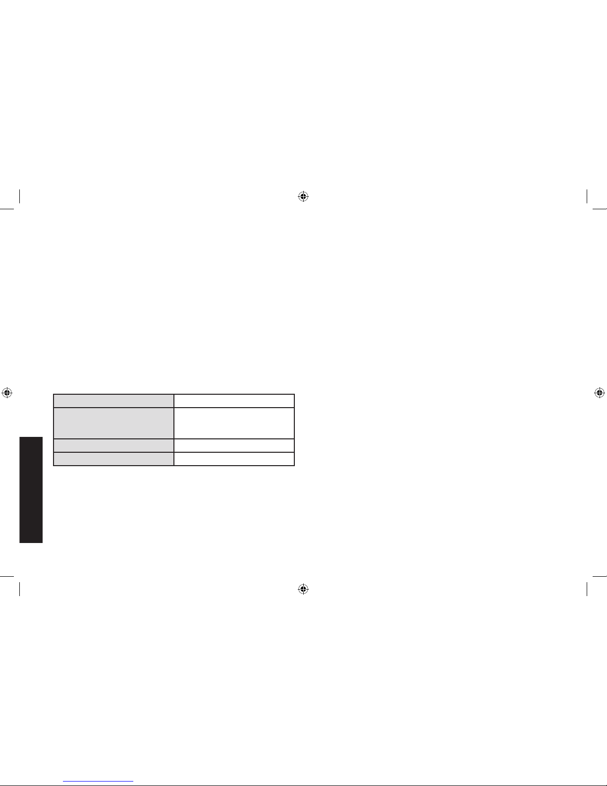
Especificaciones
Entrada 120V CA, 60Hz, 1180W
Salida 12V CC, 70A, 210A arranque del
motor (5 segundos activado, 5
minutos apagado)
Salida USB 5V CC, 3.1A max.
Salida CA 120V CA, 60Hz, 700W
Importados por Baccus Global LLC, One City Centre,
1 North Federal Highway, Suite 200, Boca Raton, FL 33432
www.dewalt12volt.com 1-888-394-3392
Copyright © 2016 DeWALT. DeWA LT® y el logotipo son
marcas comerciales de DeWALT el DeWALT Industrial Tool Co.,
o una filial de la misma y se utilizan bajo licencia. El esquema de
color amarillo y negro es una marca comerciale de herramientas y
accesorios de DeWALT.
DXAEC210_ManualENFRSP_092116.indd 76 10/19/2016 3:58:51 PM
Page 2

DXAEC210/DXAEC210CA
70A Professional Wheeled Battery Charger with 210A Engine Start
Chargeur de batterie 70A professional sur roues
avec 210A de démarrage du moteur
Cargador de batería 70A profesional de ruedas con 210A arranque del motor
INSTRUCTION MANUAL
GUIDE D’UTILISATION
MANUAL DE INSTRUCCIONES
If you have questions or comments, contact us.
Pour toute question ou tout commentaire, nous contacter.
Si tiene dudas o comentarios, contáctenos.
1-888-394-3392
BC
RD092116
DXAEC210_ManualENFRSP_092116.indd 1 10/19/2016 3:58:52 PM
Page 3

English
2
DXAEC210_ManualENFRSP_092116.indd 2 10/19/2016 3:58:52 PM
Page 4
English
3
Definitions: Safety Guidelines
The definitions below describe the level of severity for each signal
word. Please read the manual and pay attention to these symbols.
DANGER: Indicates an imminently hazardous situation which,
if not avoided, will result in death or serious injury.
WARNING: Indicates a potentially hazardous situation which,
if not avoided, could result in death or serious injury.
CAUTION: Indicates a potentially hazardous situation which,
if not avoided, may result in minor or moderate injury.
NOTICE: Indicates a practice not related to personal injury
which, if not avoided, may result in property damage.
IF YOU HAVE ANY QUESTIONS OR COMMENTS ABOUT THIS OR
ANY DeWalt TOOL, CALL US TOLL FREE AT: 1-888-394-3392.
WARNING: Read all instructions before operating product.
Failure to follow all instructions listed below may result in electric
shock, fire and/or serious injury.
70A Professional Wheeled Battery
Charger w/210A Engine Start
The DXAEC210//DXAEC210CA 70A Professional Wheeled Battery
Charger with 210A Engine Start is a DeWALT 70A battery charger that
features 210A engine start, alternator check, and battery reconditioning
functions; a USB port; and an AC power outlet.
WARNING: This apparatus or its power cord contains lead, a
chemical known to the State of California to cause cancer and birth
defect or other reproductive harm. Wash hands after handling.
Important Safety
Instructions
1. Keep these instructions.
2. Heed all warnings.
3. Follow all instructions.
4. Avoid dangerous environments. Don’t use battery chargers in
damp or wet locations. Do not use the charger in the rain or snow.
5. Clean only with a dry cloth.
6. Keep children away from the charging area. Keep the charger
away from children. This is not a toy!
7. Store indoors. When not in use, battery chargers should be stored
indoors in dry, and high or locked-up places – out of the reach
of children.
8. Unplug the battery charger when not in use.
9. Stay alert. Use common sense. Do not operate
this equipment when you are tired or impaired.
10. Only use attachments/accessories specified by
the manufacturer.
11. Use only on a flat, level surface to avoid injury
from tip-over.
12. Check for damaged parts. Any part that is damaged should be
properly repaired or replaced by manufacturer unless otherwise
indicated elsewhere in this instruction manual before further use.
Servicing is required when the apparatus has been damaged
in any way, such as power-supply cord or plug is damaged,
liquid has been spilled or objects have fallen into the apparatus,
the apparatus has been exposed to rain or moisture, does not
operate normally, or has been dropped. Contact the manufacturer
at 1-888-394-3392 for more information.
DXAEC210_ManualENFRSP_092116.indd 3 10/19/2016 3:58:52 PM
Page 5

English
4
13. Apparatus shall not be exposed to dripping or splashing and no
objects filled with liquids, shall be placed on the apparatus.
This Class B digital apparatus complies with Canadian ICES-003.
CAN ICES-3(B).
NOTE: This equipment has been tested and found to comply with
the limits for a Class B digital device, pursuant to Part 15 of the FCC
Rules. These limits are designed to provide reasonable protection
against harmful interference in a residential installation. This equipment
generates, uses and can radiate radio frequency energy and, if not
installed and used in accordance with the instructions, may cause
harmful interference to radio communications. However, there is no
guarantee that interference will not occur in a particular installation. If
this equipment does cause harmful interference to radio or television
reception, which can be determined by turning the equipment off and
on, the user is encouraged to try to correct the interference by one or
more of the following measures:
•Reorient or relocate the receiving antenna.
• Increase the separation between the equipment and the
receiver.
• Connect the equipment into an outlet on a circuit different
from that to which the receiver is connected
• Consult the dealer or an experienced radio/TV technician
for help.
NOTICE: Per FCC Part 15, changes or modifications to this equipment
not expressly approved by DeWALT could void your authority to operate
this equipment.
READ ALL INSTRUCTIONS
Specific Safety Instructions for Power Cords
•Don’t abuse the cord. Protect the power cord from being walked
on or pinched particularly at plugs, convenience receptacles, and the
point where they exit from the apparatus. Don’t abuse the power
cord. Never carry the apparatus by cord or yank it to disconnect from
receptacle. Keep the cord from heat, oil, and sharp edges. Pull by
plug rather than cord when unplugging the unit.
•Ground fault circuit interrupter (GFCI) protection should be
provided on the circuits or outlets to be used. Receptacles are
available having built in GFCI protection and may be used for this
measure of safety.
DANGER – Never alter AC Power Cord or plug provided. If it will
not fit the outlet, have a proper outlet installed by a qualified electrician.
Improper connection can result in a risk of an electric shock.
EXTENSION CORDS
An extension cord should not be used unless absolutely
necessary. Use of an improper extension cord could result in a risk
of fire and electric shock, and will void warranty.
If an extension cord must be used, make sure your extension cord
is in good condition. When using an extension cord, be sure to use
one heavy enough to carry the current your product will draw. An
undersized cord will cause a drop in line voltage resulting in loss of
power and overheating. The following table shows the correct size
to use depending on cord length and nameplate ampere rating. If in
doubt, use the next heavier gauge. The smaller the gauge number,
the heavier the cord.
DXAEC210_ManualENFRSP_092116.indd 4 10/19/2016 3:58:52 PM
Page 6
English
5
Recommended Minimum AWG Size for Extension Cords
for Battery Chargers
AC Input Rating American Wire Gage (AWG) Size of Cord
Amperes Length of Cord, feet (m)
Equal to or But less
25 (7.6) 50 (15.2) 100 (30.5) 150 (45.6)
greater than than
0 2 18 18 18 16
2 3 18 18 16 14
3 4 18 18 16 14
4 5 18 18 14 12
5 6 18 16 14 12
6 8 18 16 12 10
8 10 18 14 12 10
10 12 16 14 10 8
12 14 16 12 10 8
14 16 16 12 10 8
16 18 14 12 8 8
18 20 14 12 8 6
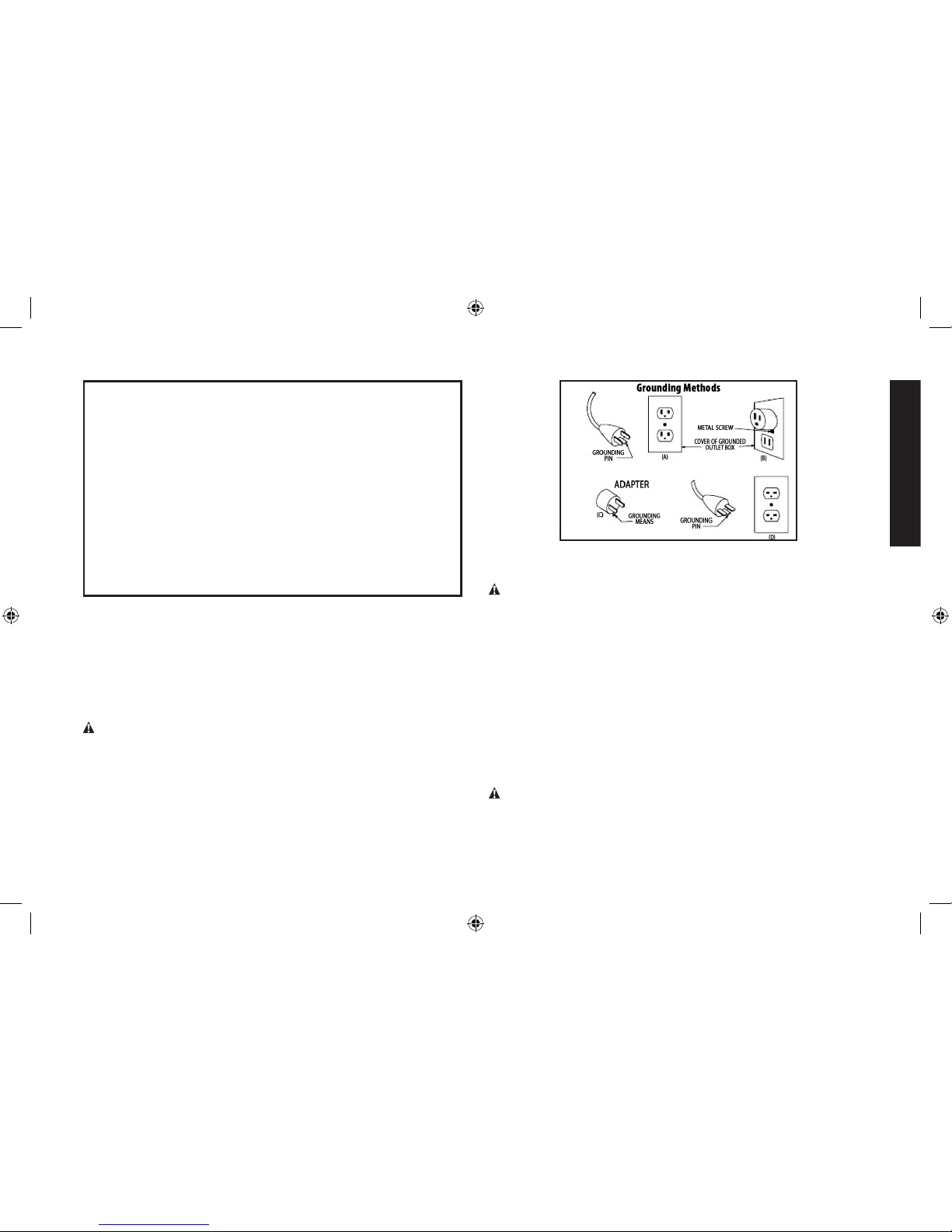
POWER CORD SAFETY
The battery charger is for use on a nominal 120 volt circuit, and has
a grounding plug that looks like the plug illustrated in Figure A. A
temporary adapter, which looks like the plug illustrated in Figures B
and C may be used to connect this plug to a two-pole receptacle as
shown in Figure B if a properly grounded outlet is not available. The
temporary adapter should be used only until a properly grounded outlet
can be installed by a qualified electrician.
DANGER: Before using an adapter as shown in the following
illustration, be certain that center screw of outlet plate is grounded.
The green-colored rigid ear or lug extending from adapter must be
connected to a properly grounded outlet– make certain it is grounded.
If necessary, replace the original outlet cover plate screw with a longer
screw that will secure the adapter ear or lug to outlet cover plate and
make ground connection to a grounded outlet.
Specific Safety Instructions for
Battery Chargers
WARNING – BURST HAZARD: Do not use the unit for charging
dry-cell batteries that are commonly used with home appliances. These
batteries may burst and cause injury to persons and damage property.
Use the unit for charging/boosting a 12 volt battery only. It is not
intended to supply power to a low-voltage electrical system other than
in a starter-motor application.
•Use of accessories and attachments: The use of any accessory
or attachment not recommended by manufacturer for use with this
battery charger could be hazardous.
•Stay alert. Use common sense. Do not operate this apparatus when
you are tired or impaired.
•Do not operate the battery charger near flammable liquids or in
gaseous or explosive atmospheres. Motors may spark, and the
sparks might ignite fumes.
WARNING: To reduce the risk of electric shock, never immerse the
battery charger in water or any other liquid, or use when wet.
DXAEC210_ManualENFRSP_092116.indd 5 10/19/2016 3:58:52 PM
Page 7

English
6
WARNING – Risk of explosive gases:
•Working in the vicinity of a lead acid battery is dangerous. Batteries
generate explosive gases during normal battery operation. For this
reason, it is of the utmost importance that each time before using the
battery charger you read this manual and follow instructions exactly.
•To reduce the risk of battery explosion, follow these instructions and
those published by the battery manufacturer and manufacturer of
any equipment you intend to use in the vicinity of the battery. Review
cautionary markings on these products and on the engine.
•This equipment employs parts (switches, relays, etc.) that produce
arcs or sparks. Therefore, if used in a garage or enclosed area, the
unit MUST be placed not less than 18 inches above the floor.
•THIS UNIT IS NOT FOR USE BY CHILDREN AND SHOULD ONLY
BE OPERATED BY ADULTS.
WARNING – To reduce the risk of fire:
•Do not operate near flammable materials, fumes, dust or gases.
•Do not expose to extreme heat or flames.
CAUTION – To reduce the risk of injury or property damage:
•NEVER ATTEMPT CHARGE A FROZEN BATTERY.
•Do not charge the battery while the engine is operating.
•Stay clear of fan blades, belts, pulleys, and other parts that can
cause injury to persons.
•Vehicles that have on-board computerized systems may be damaged
if vehicle battery is jump-started. Before jump-starting, read the
vehicle’s owner’s manual to confirm that external-starting assistance
is suitable.
•When working with lead acid batteries, always make sure someone
is close enough to provide immediate assistance in case of accident
or emergency.
•Always have protective eyewear when using this product: contact with
battery acid may cause blindness and/or severe burns. Be aware of
first aid procedures in case of accidental contact with battery acid.
•Have plenty of fresh water and soap nearby in case battery acid
contacts skin.
•If battery acid contacts skin or clothing, wash immediately with
soap and water for at least 10 minutes and get medical attention
immediately.
•Never smoke or allow a spark or flame in vicinity of vehicle battery,
engine or battery charger.
•Remove personal metal items such as rings, bracelets, necklaces and
watches when working with a lead acid battery. A lead acid battery
can produce a short circuit current high enough to weld a ring, or
similar metal object, to skin causing a severe burn.
•Be extra cautious to avoid dropping a metal tool onto the battery. It
might spark or short-circuit the battery or another electrical part, and
that may cause an explosion.
•Never allow battery acid to come in contact with this apparatus.
•Do not operate this apparatus in a closed area or restrict ventilation
in any way.
•Always turn the battery charger off by unplugging it when not in use.
•DO NOT OPEN THE BATTERY CHARGER — there are no user-
serviceable parts inside. Opening the battery charger will void
manufacturer’s warranty.
•Operate battery charger only as described in this Instruction Manual.
•Check battery charger and components periodically for wear and
tear. Return to manufacturer for replacement of worn or defective
parts immediately.
WARNING: To reduce the risk of injury, follow these instructions
and those published by the battery manufacturer and manufacturer of
any equipment you intend to use with this unit. Review cautionary
markings on this product and on engine.
Specific Safety Instructions for the USB Port
•Do not insert foreign objects into the USB Port.
DXAEC210_ManualENFRSP_092116.indd 6 10/19/2016 3:58:52 PM
Page 8

English
7
•Do not attach USB hubs or more than one personal electronic device
to the USB Port.
•Do not use this unit to operate appliances that require more than 3.1
amps in total to operate from the USB Ports.
Specific Safety Instructions for the
AC Pass Through
•Do not insert foreign objects into the AC Pass Through.
•Do not attach AC outlet taps or multi-outlet extension cords, or
attach more than one electrical appliance to the AC Pass Through.
•Observe all Safety Instructions in the “Specific Safety Instructions for
Power Cords” section of this Instruction Manual.
First Aid
•Skin: if battery acid comes in contact with skin, rinse immediately
with water, then wash thoroughly with soap and water. If redness,
pain, or irritation occurs, seek immediate medical attention.
•Eyes: If battery acid comes in contact with eyes, flush eyes
immediately, for a minimum of 15 minutes and seek immediate
medical attention.
•LCD liquid crystal display: If liquid crystal comes in contact with
your skin: Wash area off completely with plenty of water. Remove
contaminated clothing. If liquid crystal gets into your eye: Flush the
affected eye with clean water and then seek medical attention. If liquid
crystal is swallowed: Flush your mouth thoroughly with water. Drink
large quantities of water and induce vomiting. Then seek medical
attention.
SAVE THESE
INSTRUCTIONS
FOR FUTURE USE
Components (Fig. 1)
I
A. Handle
B. Negative Clamp (black)
C. Positive Clamp (red)
D. Control Panel (refer to
Fig. 2)
E. Clamp Cable Storage
Spool
F. 120 Volt AC Cable and
Plug on Storage Spool
G. Base Stand
H. Wheels (2 in total)
I. Resettable circuit
breaker (back of unit)
B C
H
A
F
G
E
D
DXAEC210_ManualENFRSP_092116.indd 7 10/19/2016 3:58:52 PM
Page 9

English
8
Control Panel (Fig. 2)
A. LCD Screen
B. AC Pass-Through
C. Battery Charge Button
D. Battery Voltage Button
E. Engine Start Button
F. Alternator Check Button
G. Battery Recondition Button
H. Battery Type Selector Button
I USB Power Button
J. USB Port
K. USB Power/Fault Indicator
70 Amp Battery Charger 210 Amp Engine Start
70A Chargeur de Batterie 210A Démarrage du Moteur
Engine Start
Démarrage du Moteur
120V AC
6A MAX
3.1A
Recondition
Rénover
Alternator Test
Alternateur Vérier
Battery Type
Batterie Catégorie
Reverse Polarity
Polarité inversée
SEC.
VA
ALT
Engine
Start
Recond
Battery
Type
Battery
Voltage
Alt Test USB
70A Cargador de Batería 210A Arranque del Motor
A
C
E G ID F H
K
J
B
DXAEC210_ManualENFRSP_092116.indd 8 10/19/2016 3:58:53 PM
Page 10
English
9
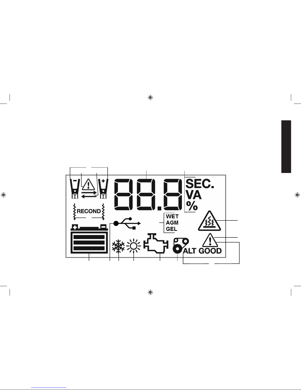
LCD Screen (Fig. 3)
A. Clamp Icons
B. Alarm Icon
C. Reverse Polarity Icons
D. Digital Display (varies by
function)
E. Seconds/Voltage/Ampere/
Percentage Indicator
F. Battery Recondition
Indicator
G. Battery Reconditioning
Icons
H. Battery Type Indicator
I. Overheat Alarm Icon
J. Fault Icon
I
K
CB
A
F
G
Q
D
E
J
P
O N M L
H
K. Alternator Good/Fault
Indicators
L. Alternator Icon
M. Pump Engine Icon
N. High Temperature
Compensation Icon
O. Low Temperature
Compensation Icon
P. USB Icon
Q. Battery Icon
DXAEC210_ManualENFRSP_092116.indd 9 10/19/2016 3:58:53 PM
Page 11
English
10
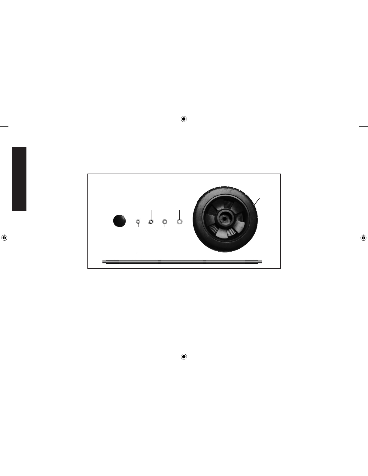
Assembling the Unit (Fig. 4)
Wheel Set Assembly
PARTS:
Wheel Shaft
Wheel Cover
(2 in total)
Wheel
Nut
(2 in total)
Ø6mm
Spring
Washer
(2 in total)
Ø6mm Plain
washer
(2 in total)
Ø8mm
Plain
washer
(2 in total)
Wheels
(2 in total)
DXAEC210_ManualENFRSP_092116.indd 10 10/19/2016 3:58:53 PM
Page 12
English
11
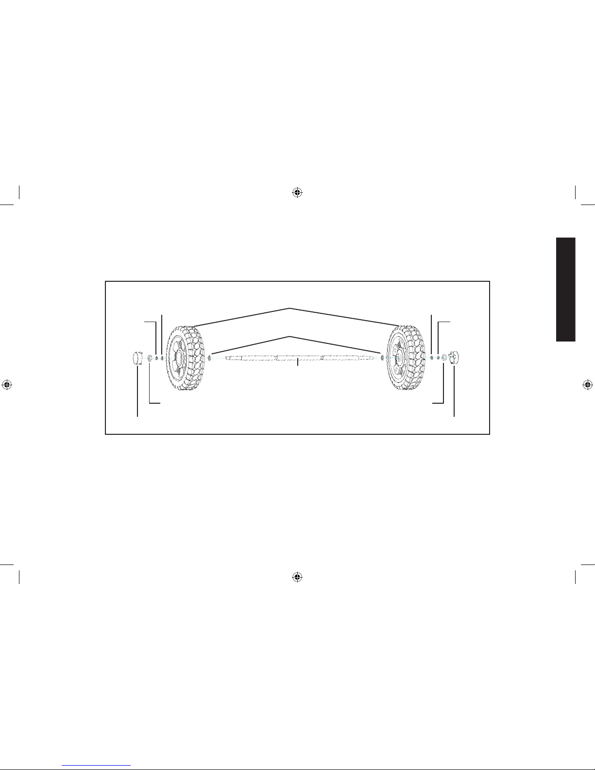
ASSEMBLY:
Ø8mm Plain Washers
Wheel Shaft
Wheels
Ø6mm
Spring
Washer
Wheel Nuts
Wheel Covers
Ø6mm
Plain
Washer
Ø6mm
Plain
Washer
Ø6mm
Spring
Washer
Wheel Nuts
Wheel Covers
1. Align one Wheel Set (Ø8mm Plain Washer, Wheel, Ø6mm Plain
Washer, Ø6mm Spring Washer and Wheel Nut, assembled in the
sequence shown in the illustration) and attach to each end of the
Wheel Shaft.
2. Screw the Wheel Nuts for each end of the Wheel Shaft.
3. Snap the Wheel Covers into the centre slot of each Wheel.
DXAEC210_ManualENFRSP_092116.indd 11 10/19/2016 3:58:53 PM
Page 13
English
12
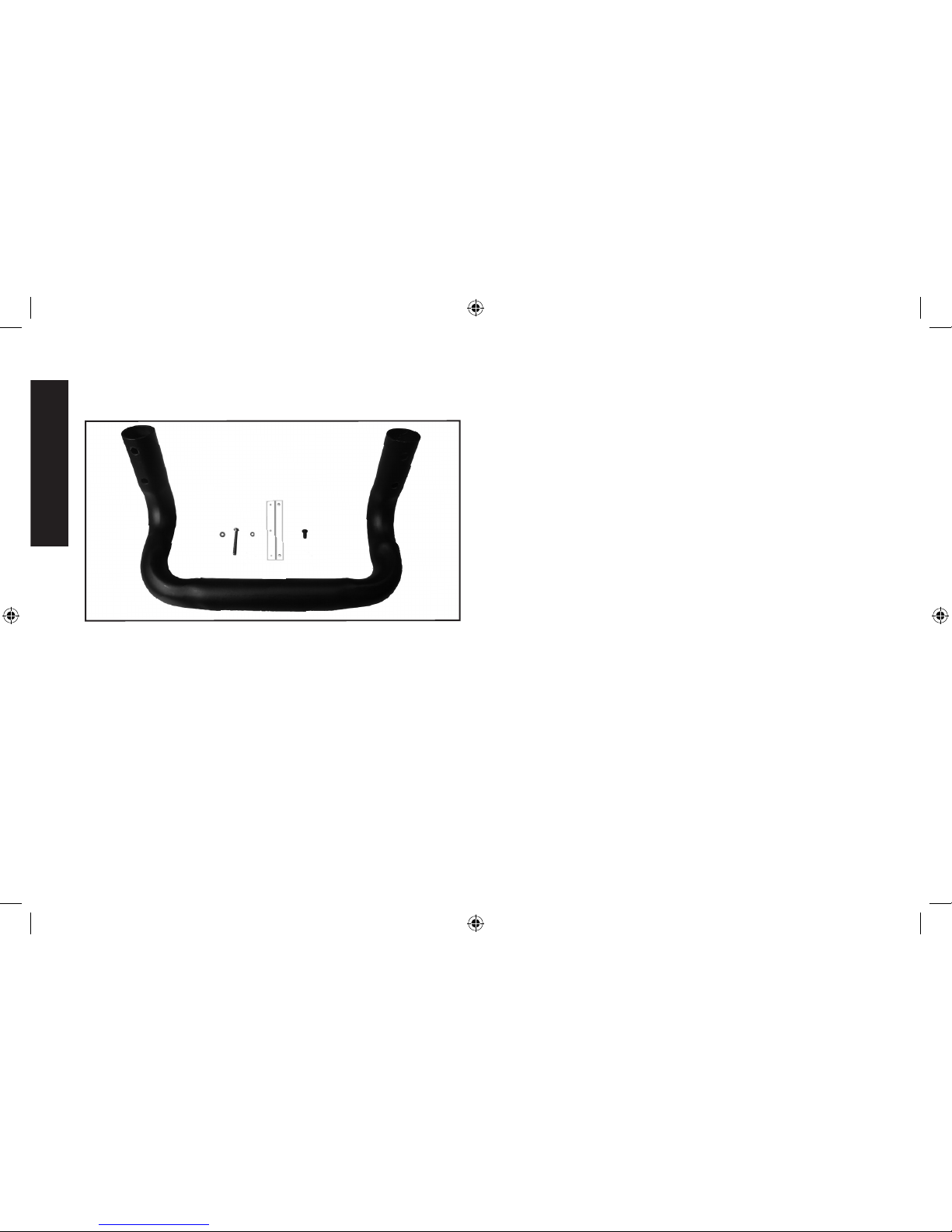
Base Stand and Wheel Set Installation
PARTS:
A
BCD F
E
A. Base Stand
B. Ø4mm Plain Washer
(4 in total)
C. Base Stand Screw
(4x22mm) (4 in total)
D. Ø4mm Spring Washer
(7 in total: 4 for Base Stand,
3 for Wheel Set Lock)
E. Wheel Set Lock
F. Wheel Set Lock Screw
(4x8mm) (3 in total)
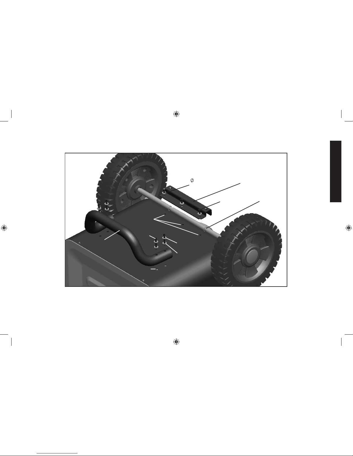
ASSEMBLY:
1. Turn the unit upside down with the unit base at top as shown.
2. Position the Base Stand as shown in the illustration on the following
page, aligning the four Base Stand Screws, Ø4mm Spring Washers
and Ø4mm Plain Washers with the Base Stand Screw Holes
through the apertures on the Base Stand in the sequence shown
in the illustration.
3. Screw the four Base Stand Screws into the Base Stand Screw
Holes. Do not over-tighten.
4. Position the Wheel Set Assembly as shown in the illustration.
5. Align the Wheel Set Lock with the three Wheel Set Screw Holes. It
should be centered over the Wheel Shaft Slots.
6. Screw the three Wheel Set Lock Screws with the three Ø4mm
Spring Washers in the sequence shown in the illustration into the
Wheel Lock Screw Holes through the Wheel Set Lock. Do not
over-tighten.
DXAEC210_ManualENFRSP_092116.indd 12 10/19/2016 3:58:54 PM
Page 14
English
13
Wheel Set Lock
Base Stand
Wheel
Shaft Slot
Wheel Set Lock
Screw Holes
4mm
Spring
Washers
Wheel Set
Lock Screws
Ø4mm Plain
Washers
Base Stand
Screws
Base Stand
Screw Holes
Ø4mm Spring
Washers
DXAEC210_ManualENFRSP_092116.indd 13 10/19/2016 3:58:54 PM
Page 15

English
14
Preparing to Charge
1. Be sure the area around battery is well ventilated while the battery
is being charged.
2. Remove the battery completely from a boat/airplane or any confined
area before charging.
3. If it is necessary to remove battery from a vehicle to charge or to
clean terminals, always remove the grounded terminal from the
battery first. Make sure all accessories in the vehicle are turned off,
so as not to cause an electrical arc.
4. Clean the battery terminals, taking care to avoid getting corrosive
material in your eyes.
5. Add distilled water in each cell until battery acid reaches the
level specified by the battery manufacturer. This helps purge
excessive gas from cells. Do not overfill. For a battery without cell
caps (maintenance free), carefully follow manufacturer’s charging
instructions.
6. Study all battery manufacturer’s specific precautions, such
as removing or not removing cell caps while charging, and
recommended rates of charge.
7. Determine the voltage of the battery to be charged by referring to
the vehicle manual. This unit is for charging a 12 volt battery only.
CHARGER LOCATION
•IMPORTANT: Only use the unit on a flat, level surface to avoid
movement during operation. Take proper precautions to secure the
wheels to avoid shifting or movement before use.
•Locate the charger as far away from the battery as cables permit.
•Never place the charger directly above the battery being charged;
gases from the battery will corrode and damage the charger.
•Never allow battery acid to drip on the charger when reading gravity
or filling the battery.
•Never operate the charger in a closed-in area or restrict ventilation
in any way.
•A marine (boat) battery must be removed and charged on shore.
•Do not set a battery on top of the charger.
CONNECTING THE CHARGER
CONNECTION PRECAUTIONS
•Connect and disconnect output clamps only after removing AC Power
Cord from electric outlet.
•Never allow the clamps to touch each other.
•Attach the clamps to the battery and chassis as indicated in the
appropriate section (“Charging a battery installed in a vehicle” or
“Charging a battery that has been removed from a vehicle”).
FOLLOW THESE STEPS WHEN THE BATTERY IS INSTALLED
IN A VEHICLE
WARNING – A spark near the battery may cause an explosion. To
reduce risk of a spark near the battery:
1. Do not charge the battery while the engine is operating.
2. Position AC and clamp cords to reduce risk of damage by hood,
door, or moving engine part.
3. Stay clear of fan blades, belts, pulleys, and other parts that can
cause injury to persons.
4. Check polarity of the battery posts. The positive post (marked POS,
P, +) usually has a larger diameter than the negative battery post
(marked NEG, N, –).
5. Determine which post of battery is grounded (connected) to the
chassis. If negative post is grounded to chassis (as in most vehicles),
see 6. If positive post is grounded to the chassis, see 7.
6. For a negative-grounded vehicle, connect the positive (red) clamp
from the battery charger to the positive (POS, P, +) ungrounded post
of battery. Connect the negative (black) clamp to vehicle chassis or
engine block away from battery. Do not connect clip to carburetor,
DXAEC210_ManualENFRSP_092116.indd 14 10/19/2016 3:58:54 PM
Page 16
English
15
fuel lines, or sheet-metal body parts. Connect to heavy gauge metal
part of the frame or engine block.
7. For a positive-grounded vehicle, connect the negative (black) clamp
from the battery charger to the negative (NEG, N, –) ungrounded
post of battery. Connect positive (red) clamp to vehicle chassis or
engine block away from battery. Do not connect clip to carburetor,
fuel lines or sheet-metal body parts. Connect to a heavy gauge
metal part of the frame or engine block.
8. See vehicle operating instructions or battery manual for length of
charge information.
9. When disconnecting charger, unplug the AC Power Cord, remove
the clamp from vehicle chassis, and then remove the clamp from
the battery terminal.
FOLLOW THESE STEPS WHEN THE BATTERY HAS BEEN
REMOVED FROM A VEHICLE
WARNING – A spark near the battery may cause an explosion. To
reduce risk of a spark near the battery:
1. Check polarity of the battery posts. The positive post (marked POS,
P, +) usually has a larger diameter than the negative battery post
(marked NEG, N, –).
2. Attach a 24-inch (minimum length) AWG #6 insulated battery cable
to the negative battery post (marked NEG, N, –).
3. Connect the positive (red) clamp to the positive battery post (red
or marked POS, P, +).
4. Stand as far back from the battery as possible, and do not face
the battery when making final connection.
5. Carefully connect the negative (black) clamp to the free end of the
battery cable connected to the negative terminal.
6. When disconnecting the charger, always do so in reverse sequence
of connecting procedure and break first connection while as far
away from battery as practical.
NOTE: A marine (boat) battery must be removed and charged on
shore. To charge it on board requires equipment specifically designed
for marine use. This unit is NOT designed for such use.
Charging the Battery
IMPORTANT: If a problem is encountered during the battery charging
process, refer to the “Indications and Faults – All Modes” section that
follows the battery charging directions.
PROCEDURE
1. Plug the battery charger’s AC Power Cord into a functioning
AC outlet. A beep will sound and the LCD Screen will show the
following:
The empty Battery Icon will light solid to indicate the Battery Clamps
are not yet connected to the battery.
2. Connect the battery charger to the battery using the battery clamps,
following the appropriate directions in the “Preparing to Charge”
section at the front of this Instruction Manual.
DXAEC210_ManualENFRSP_092116.indd 15 10/19/2016 3:58:54 PM
Page 17
English
16
If the clamps are properly connected with regard to polarity, a beep
will sound and the LCD Screen will show the following, indicating
the unit is in Standby Mode:
The Digital Display shows the voltage of the connected battery.
The bars on the Battery Icon represent the charge level of the
connected battery. The Clamp Icons, Battery Icon and the Battery
Type Indicator light solid.
NOTES:
The charger allows you to select the appropriate battery type (WET,
AGM or GEL) for efficient and safe charging. The default selection
is “WET” battery type. Press the Battery Type Selector Button until
the desired battery type indicator lights. A beep will sound for each
press of the button.
CAUTION – To reduce the risk of injury or property damage:
Selecting an incorrect battery type may adversely affect charging
performance. Refer to the battery manufacturer’s specifications
to determine the battery type. Make this selection BEFORE
proceeding to the next step, as battery type cannot be selected
once charging has begun.
In Standby Mode, the Digital Display shows the voltage (V) of the
connected battery by default. Press the Battery Voltage Button
once to show the charge status of the battery as a percentage (%)
of full. Pressing the Voltage Button cycles through different standby
status views of the connected battery.
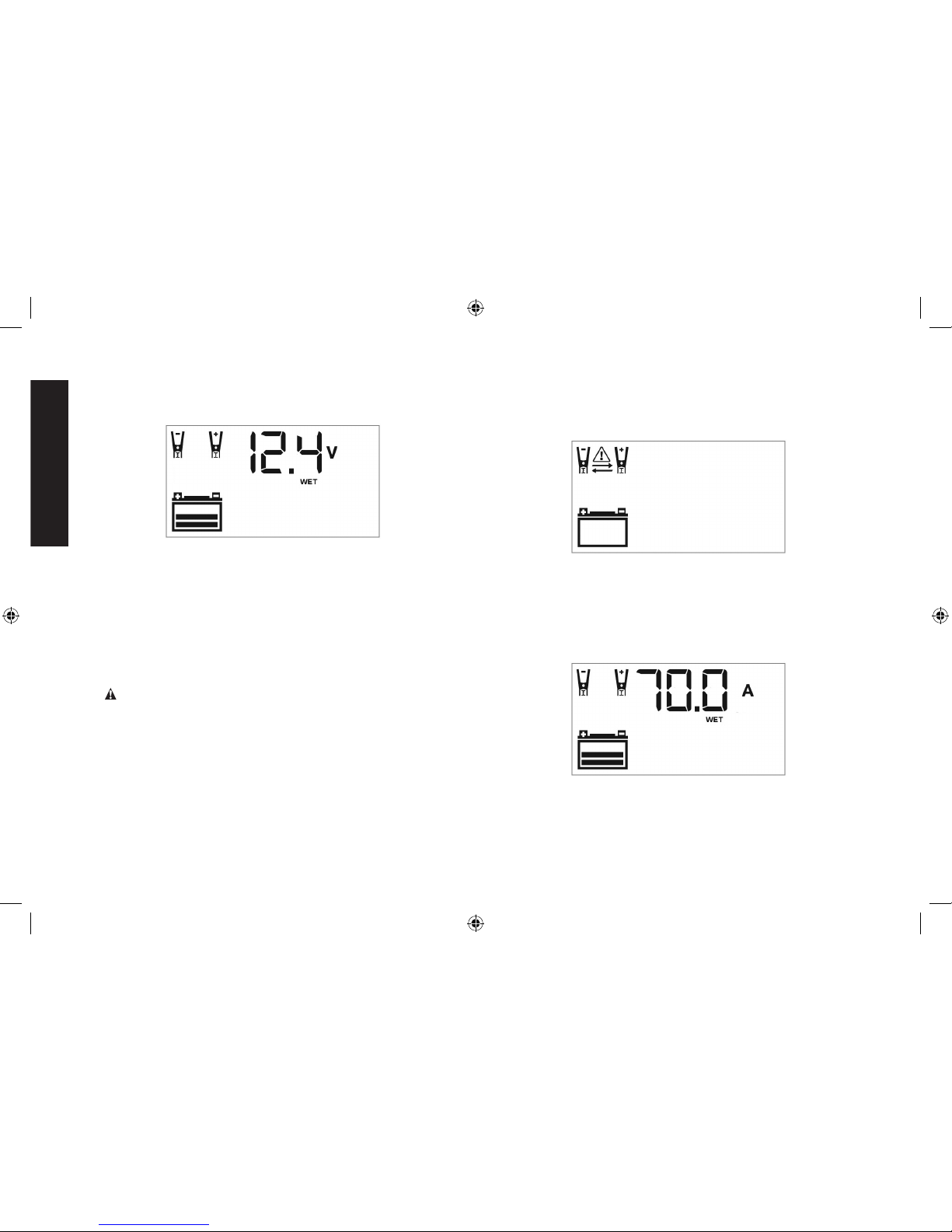
IMPORTANT: If the battery clamps are connected incorrectly
with regard to polarity, the LCD Screen shows the following:
The (empty) Battery Icon and the Clamp Icons light solid. The Alarm
Icon, Reverse Polarity Icons, and the “+” and “–” signs on both the
Clamp Icons and the Battery Icon flash. The unit emits a continuous
warning sound until the clamps are disconnected. Remove the
clamps and then reconnect the clamps properly.
3. When the clamps are connected correctly, press the Battery Charge
Button. The LCD Screen will show the following:
The Digital Display shows the output current that is charging the
battery. The Clamp Icons and the Battery Type Indicator light solid
and the bars on the Battery Icon will change from empty to solid
(bottom to top) to indicate the unit is in Charging Mode.
DXAEC210_ManualENFRSP_092116.indd 16 10/19/2016 3:58:54 PM
Page 18

English
17
NOTES:
A. The maximum output current is approximately 70A.
B. If the battery is already charged to nearly full capacity, the
unit’s output current may be automatically reduced by a few
amperes, despite the maximum output current rating of 70A.
C. The charging process will start automatically approximately
one minute after the unit is properly connected to a battery if
no other actions are taken.
D. The charging process can be terminated by pressing the
Battery Charge Button again to stop the function. The unit
will revert to the Standby Mode. It will automatically restart the
charging process after approximately one minute if no other
actions are taken.
E. In Charging Mode, the Digital Display shows the output
current (A) that is charging the battery by default. Press the
Battery Voltage Button once to show the voltage (V) of the
connected battery. Press the Battery Voltage Button again to
show the charge status of the battery as a percentage (%)
of full. Pressing the Voltage Button cycles through different
charging status views of the connected battery.
F. Once the unit is in Charging Mode, the Battery Type cannot
be modified. To change Battery Type, terminate the charging
process and then reselect in Standby Mode.
4. When the battery is completely charged, the unit automatically goes
into Float Charge Mode. In this mode, the unit monitors the battery
voltage and charges as necessary to assure the battery maintains
a full charge. The unit remains in Float Charge Mode as long as the
charger is connected to the battery and plugged into a functioning
AC outlet. The LCD Screen shows the following:
The Digital Display shows “FLO” indicating that the unit is in Float
Charge Mode. The Clamp Icons, the Battery Icon (with three bars),
and the Battery Type Indicator will light solid.
NOTE: In Float Charge Mode, the Digital Display shows “FLO” by
default. Press the Battery Voltage Button once to show the voltage
(V) of the connected battery. Press the Battery Voltage Button again
to show the charge status of the battery as a percentage (%) of
full. Pressing the Voltage Button cycles through different charging
status views of the connected battery.
When the unit is in Float Charge Mode, the Battery Type cannot be
modified. To change Battery Type, terminate the charging process
and then reselect in Standby Mode.
5. When disconnecting the battery charger, unplug the AC Power
Cord, remove the clamp from the vehicle chassis, and then remove
the clamp from the battery terminal.
DXAEC210_ManualENFRSP_092116.indd 17 10/19/2016 3:58:54 PM
Page 19
English
18
Indications and Faults –
All Charging Modes
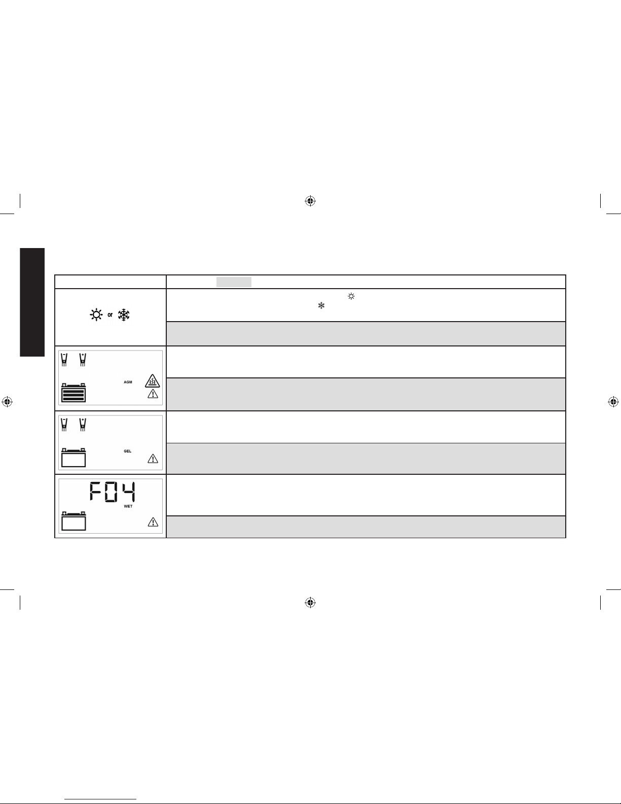
LCD Screen Shows: Indication | Solution:
Temperature Compensation Activated: The “ ” Icon will appear if the surrounding ambient temperature
is higher than approximately 40°C. The “ ” Icon will appear if the surrounding ambient temperature is lower
than 0°C. This is not a fault code, but indicates that the unit’s temperature compensation feature is operating.
No user action is required.
Overheat Protection Activated: If the charger is overheated, the charging process automatically terminates.
The Fault Icon and the Overheat Alarm Icon flash. The (full) Battery Icon, Clamp Icons and the Battery Type
Indicator light solid.
Disconnect all battery charger connections and allow the charger to cool for several minutes. Make sure there
is adequate ventilation around the unit before attempting to charge again.
Battery Problem Detected: The charger automatically checks the battery condition 3 minutes after the charging
process starts. If the charger detects a problem with a battery, the charging process automatically terminates.
The Fault Icon and the (empty) Battery Icon flash. The Clamp Icons and the Battery Type Indicator light solid.
Disconnect all battery charger connections. Have the battery checked by a qualified technician.
Possible Battery Problem Detected: If the battery is not fully charged after 18 hours of continuous charging,
the battery may have internal damage and will not accept a charge. After 18 hours, the charging process
automatically terminates. The Digital Display shows “F04” and the Battery Type Indicator lights solid. The Fault
Icon and the (empty) Battery Icon flash.
Disconnect all battery charger connections. Have the battery checked by a qualified technician.
DXAEC210_ManualENFRSP_092116.indd 18 10/19/2016 3:58:54 PM
Page 20
English
19
Reconditioning the Battery
Periodic reconditioning is recommended to maintain a battery’s
optimum performance. Battery recondition sends a series of electrical
pulses to break up the crystalline form of lead sulfate and turn these
chemicals into useful battery electrolytes.
1. Refer to the “Charging the Battery” section of this Instruction
Manual. Set up the battery charger and connect to the battery
following steps 1 and 2. The unit will be in Standby Mode.
2. Press the Battery Recondition Button once. A beep will sound and
the Digital Display will show the following:
The Battery Recondition Indicator and the Battery Icon light solid.
The Battery Recondition Icons flash, and the bars on the Battery
Icon change from solid to empty (top to bottom) repeatedly.
The process stops automatically after 24 hours. To end the process
sooner, press the Battery Recondition Button once again to turn it
off. A beep will sound and the unit will return to Standy Mode.
More than 24 hours may be needed to restore performance on
some batteries. If so, repeat the process.
3. When disconnecting the battery charger, unplug the AC Power
Cord, and then disconnect the battery charger from the battery
following the last step of the appropriate set of directions in the
“Preparing to Charge” section of this Instruction Manual.
IMPORTANT: If 5 cycles of reconditioning does not improve battery
performance, discontinue and recycle the battery.
Checking the Alternator
PART 1
No Load (turn OFF all vehicle’s accessories): The vehicle battery
must be fully charged before testing the alternator. Run the engine
long enough to achieve normal idle speed and verify there is a no-load
voltage.
1. Refer to the “Charging the Battery” section of this Instruction
Manual. Set up the battery charger and connect to the battery
following steps 1 and 2. The unit will be in Standby Mode.
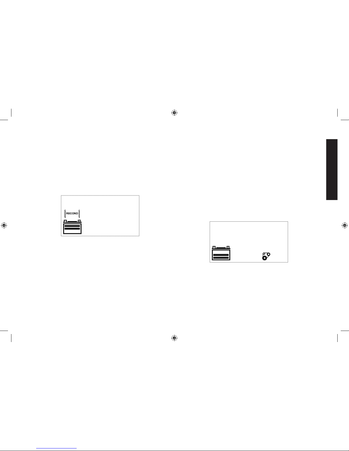
2. Press the Alternator Check Button to start the check. The Digital
Display shows the following to indicate the unit is analyzing the
alternator:
The Alternator Icon will flash and the Battery icon with two bars will
light solid.
DXAEC210_ManualENFRSP_092116.indd 19 10/19/2016 3:58:54 PM
Page 21
English
20
3. If the unit detects that the alternator is good, the LCD Screen shows
the following:
The Alternator Icon, “ALT GOOD” and the (full) Battery Icon will light
solid.
4. If the unit detects that the alternator is out of typical voltage range,
the LCD Screen shows the following:
The Fault Icon will flash. The Alternator Icon, “ALT” and the (empty)
Battery Status Icon will light solid.
5. Press the Alternator Check Button again to stop the check.
PART 2
Under Load (accessories ON): Next, load the alternator by turning
on as many accessories as possible (except for the A/C and Defrost).
1. Refer to the “Charging the Battery” section of this Instruction
Manual. Set up the battery charger and connect to the battery
following steps 1 and 2. The unit will be in Standby Mode.
2. Press the Alternator Check Button to start the check. The Digital
Display shows the following to indicate the unit is analyzing the
alternator:
The Alternator Icon will flash and the Battery icon with two bars will
light solid.
3. If the unit detects that the alternator is good, the LCD Screen
shows the following:
The Alternator Icon, “ALT GOOD” and the (full) Battery Icon will light
solid.
DXAEC210_ManualENFRSP_092116.indd 20 10/19/2016 3:58:54 PM
Page 22
English
21
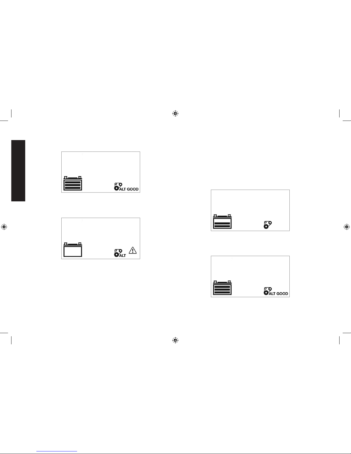
4. If the unit detects that the alternator is out of typical voltage range,
the LCD Screen shows the following:
The Fault Icon will flash. The Alternator Icon, “ALT” and the (empty)
Battery Status Icon will light solid.
5. Press the Alternator Check Button again to stop the check.
6. When disconnecting the battery charger, unplug the AC Power
Cord, and then disconnect the battery charger from the battery
following the last step of the appropriate set of directions in the
“Preparing to Charge” section of this Instruction Manual.
Notes Concerning the Alternator Check Function:
A. IMPORTANT: This check may not be accurate for every make,
manufacturer and model of vehicle. Check only 12 volt systems.
B. The unit may detect that the alternator is out of typical
voltage range because someone has added a number of
accessory loads on the charging system, thereby increasing
current demand from the alternator. MAKE SURE THAT THE
ALTERNATOR IS RATED TO SUPPORT THE APPLICATION.
Engine Start
1. Refer to the “Charging the Battery” section of this Instruction
Manual. Set up the battery charger and connect to the battery
following steps 1 and 2. The unit will be in Standby Mode.
2. Press the Engine Start Button once. A beep will sound and the
LCD Screen shows the following:
The Pump Engine Icon flashes. The Digital Display shows the
countdown to indicate the unit is in Engine Start Mode. The bars
on the Battery Icon will change from empty to solid (bottom to top)
repeatedly. The Clamp Icons and the Battery Icon will light solid.
NOTES:
A. The Engine Start function may not be started if the battery
charger detects that the battery is at full capacity (fully
charged).
B. The Engine Start countdown process can be terminated by
pressing the Engine Start Button again to stop the function.
DXAEC210_ManualENFRSP_092116.indd 21 10/19/2016 3:58:54 PM
Page 23
English
22
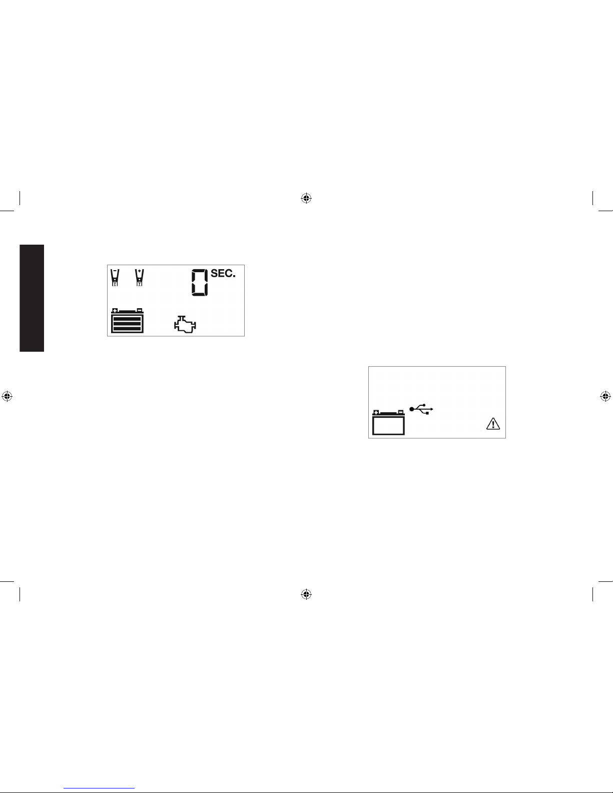
3. When “0” is reached, a beep will sound and the LCD Screen will
show the following:
The Pump Engine Icon will light solid and the Digital Display
shows “0 SEC” to indicate the vehicle is ready to start. The
Clamps Icon and the Battery Icon light solid. The bars on the
Battery Icon will change from empty to solid (bottom to top)
repeatedly.
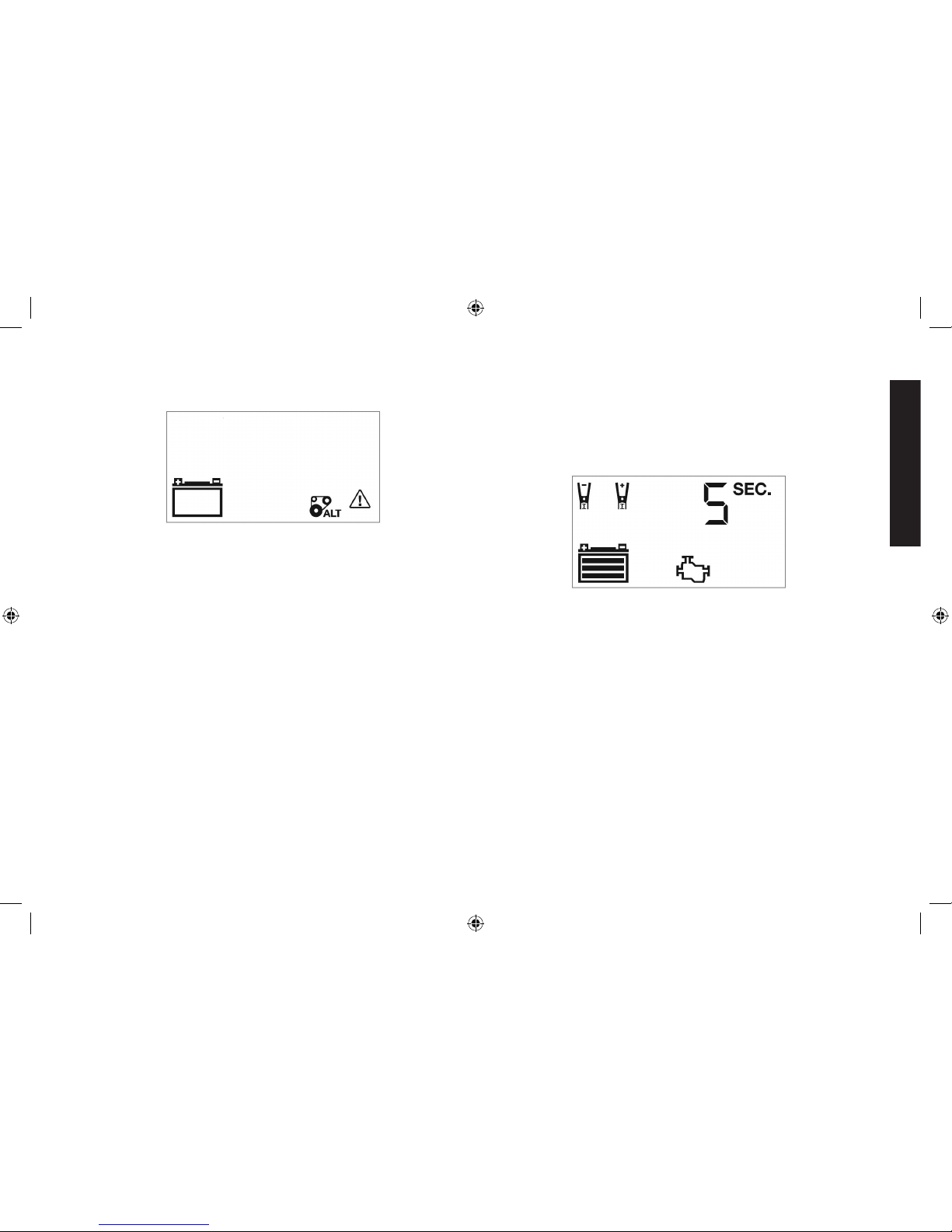
4. Crank the engine using manufacturer’s guidelines, typically in 3 to
5 second bursts. The Digital Display shows “5 SEC” (a 5-second
countdown to use as a timer when cranking the engine).
5. After cranking, the unit will automatically adjust the charging current
to 7.5A for 5 minutes, and then revert to Charging Mode. To stop
charging, press the Battery Charge Button.
IMPORTANT: The Engine Start function requires a resting/cooling
period between attempts. Wait 4 to 5 minutes before a second
attempt at starting the engine, if needed.
6. When disconnecting the battery charger, unplug the AC Power
Cord, and then disconnect the battery charger from the battery
following the last step of the appropriate set of directions in the
“Preparing to Charge” section of this Instruction Manual.
USB Port
The USB Power Button and the USB Port are located on the front of
unit. The USB Power/Fault Indicator is a translucent ring around the
USB Port. Refer to Fig. 2 to locate.
Important Notes Concerning the USB Port
1. This unit’s USB Port does not support data communication. It only
provides power to an external USB-powered device. The USB Port
provides up to 3.1A (5V).
2. When the USB Port is in use, the unit will monitor for the following
USB fault conditions: thermal fault, overload and short circuit. If a
fault condition exists the USB Power/Fault Indicator will flash blue.
In any of these cases, the LCD screen will continuously display the
following:
The USB Icon and the Fault Icon will flash. The USB Port will
automatically shut down. Should this occur:
a. Disconnect the USB-powered device and press the USB Power
Button again to turn off the USB Port immediately.
b. Allow the unit to cool down for several minutes before attempting
to use the USB Ports again.
c. If a fault occurs again, make sure that the draw of the USB device
plugged into the USB Port does not exceed 3.1A.
d. If an individual USB device is within specifications and the fault
occurs, have the USB device checked for malfunction and do
not continue to use it with this USB Port.
DXAEC210_ManualENFRSP_092116.indd 22 10/19/2016 3:58:55 PM
Page 24

English
23
3. Some household USB-powered electronics will not operate with
this unit.
USING THE USB PORT
1. Plug the battery charger’s AC Power Cord into a functioning
AC outlet. A beep will sound and the LCD Screen will show the
following:
The empty Battery Icon will light solid to indicate the Battery Clamps
are not yet connected to a battery.
2. Press the USB Power Button to turn on the USB Port. A beep will
sound, the USB Power/Fault Indicator around the USB Port will light
blue and the LCD Screen will continuously display the following:
The USB Icon will light solid, indicating the USB port is ready to use.
3. Plug the USB-powered device into the USB power port and operate
normally.
4. Press the USB power button again to turn off the USB Ports.
AC Pass Through
This unit features a 120V AC Pass Through. When using this feature,
follow all instructions and warnings found in the “Specific Safety
Instructions for the AC Pass Through” in the front of this Instruction
Manual.
NOTE: The 120V AC Pass Through is protected by a circuit breaker
located on the back of the unit (see Fig. 1). If the 120V AC Pass Through
shuts down when it is in use, this circuit break may need to be reset.
Do this by pushing it back into the unit until it locks in place. Refer to
the “Troubleshooting” sections for more information.
Care and Maintenance
WARNING: To reduce the risk of electric shock, unplug the battery
charger from the outlet before attempting any maintenance or cleaning.
Turning off the controls will not reduce this risk.
CLEANING AND STORAGE
•Store the unit in a clean, dry, cool place when not in use.
•Clean the unit casing and cords (as necessary) with a dry (or slightly
damp) cloth. Ensure that unit is completely disconnected from battery
and power source before cleaning.
•To maintain the operating condition and maximize the life of the
charger cords, always coil them loosely on the built-in storage spool
when not in use. Do not wrap them around the unit or crimp them
with a tight band.
DXAEC210_ManualENFRSP_092116.indd 23 10/19/2016 3:58:55 PM
Page 25

English
24
Troubleshooting
Problem Possible Solution
Unit fails to turn on Check that the charger is properly
connected to a live 120 volt AC outlet.
Unit fails to charge Check that the charger is properly
connected to a live 120 volt AC outlet.
If the battery to be charged has fallen below
2 volts, the battery cannot be recharged
with this charger.
Make sure a proper polarity cable
connection has been established.
AC Pass Through
will not power
appliance
Check that the battery charger is properly
connected to a live 120 volt AC Outlet.
Make sure the appliance is properly
connected to the AC Pass Through and
that the appliance is turned on.
Mark sure that the total draw of the AC
appliance connected to the AC Pass
Through does not exceed 700W.
The internal circuit breaker on the back
of unit may have popped out, indicating
that it needs to be reset. Allow a cooling
period of several minutes, then push the
circuit breaker forward until it locks back
into the unit
Problem Possible Solution
USB Port will not
power appliance
Make sure the USB Power Button has
been turned on.
Make sure the USB Power/Fault Indicator
lights solid blue. If a fault condition exists
in the USB Port, the USB Power/Fault
Indicator will flash blue. Refer to the
Important Notes in the “Using the USB
Port” section to remedy any faults.
Make sure that the draw of the USB device
plugged into the USB Port does not exceed
5V/3.1A.
Some USB-powered household electronics
will not operate with this USB charging/
power port. Check the manual of the
corresponding electronic device to confirm
that it can be used with this type of USB
charging/power port.
Accessories
WARNING: Since accessories, other than those offered by
DEWALT, have not been tested with this product, use of such
accessories with this unit could be hazardous. To reduce the risk of
injury, only DEWALT recommended accessories should be used with
this product.
If you need assistance regarding accessories, please contact the
manufacturer at 1-888-394-3392 or CustomerService@dewalt12volt.
com.
DXAEC210_ManualENFRSP_092116.indd 24 10/19/2016 3:58:55 PM
Page 26

English
25
Service Information
Whether you need technical advice, repair, or genuine factory
replacement parts, contact the manufacturer at 1-888-394-3392 or
CustomerService@dewalt12volt.com.
One Year Limited Warranty
The manufacturer warrants this product against defects in material
and workmanship for a period of one (1) year from the date of retail
purchase by the original end-user purchaser (“Warranty Period”).
If there is a defect and a valid claim is received within the Warranty
Period, the defective product can be repaired, replaced or refunded,
without charge, in the following ways: (1) Return the product to the
manufacturer for repair, replacement or refund at manufacturer’s option.
Proof of purchase may be required by manufacturer. (2) Return the
product to the retailer where product was purchased for an exchange
(provided that the store is a participating retailer). Returns to retailer
should be made within the time period of the retailer’s return policy for
exchanges only (usually 30 to 90 days after the sale). Proof of purchase
may be required. Please check with the retailer for their specific return
policy regarding returns that are beyond the time set for exchanges.
This warranty does not apply to: accessories, bulbs, fuses and batteries;
defects resulting from normal wear and tear, accidents; damages
sustained during shipping; alterations; unauthorized use or repair;
neglect, misuse, abuse; and failure to follow instructions for care and
maintenance for the product.
This warranty gives you, the original retail purchaser, specific legal
rights and you may have other rights which vary in certain states or
provinces. This product is not intended for commercial use.
90 DAY REFUND POLICY
If you are not completely satisfied with the performance of this product
for any reason, you can return it within ninety (90) days from the date
of purchase with a receipt for a full refund.
Please complete the Product Registration Card and return within
30 days from purchase of the product to: Baccus Global LLC, One
City Centre, 1 North Federal Highway, Suite 200, Boca Raton, FL
33432. Baccus Global LLC, toll-free number: 1-888-394-3392. www.
dewalt12volt.com
Specifications
Input 120V AC, 60Hz, 1180W
Output 12V DC, 70A, 210A Engine Start
(5 seconds ON, 5 minutes OFF)
USB Output 5V DC, 3.1A max.
AC Output 120V AC, 60Hz, 700W
Imported by Baccus Global LLC, One City Centre,
1 North Federal Highway, Suite 200, Boca Raton, FL 33432
www.dewalt12volt.com 1-888-394-3392
Copyright © 2016 DeWALT. DeWA LT® and the DeWALT Logo are
trademarks of the DeWALT Industrial Tool Co., or an affiliate thereof
and are used under license. The yellow/black color scheme is a
trademark for DeWALT power tools & accessories.
DXAEC210_ManualENFRSP_092116.indd 25 10/19/2016 3:58:55 PM
Page 27

Français
26
Définitions: lignes directrices en
matière de sécurité
Les définitions ci-dessous décrivent le niveau de danger pour
chaque mot-indicateur employé. Lire le mode d’emploi et porter
une attention particulière à ces symboles.
DANGER: indique une situation dangereuse imminente qui,
si elle n’est pas évitée, entraînera la mort ou des blessures
graves.
AVERTISSEMENT : indique une situation potentiellement
dangereuse qui, si elle n’est pas évitée, pourrait entraîner la
mort ou des blessures graves.
ATTENTION : indique une situation potentiellement
dangereuse qui, si elle n’est pas évitée, pourrait entraîner des
blessures légères ou modérées.
AVIS : indique une pratique ne posant aucun risque de
dommages corporels mais qui par contre, si rien n’est fait pour
l’éviter, pourrait poser des risques de dommages matériels.
POUR TOUTE QUESTION OU REMARQUE AU SUJET DE CET OUTIL
DeWALT
, COMPOSEZ LE NUMÉRO SANS FRAIS : 1-888-394-3392.
AVERTISSEMENT : Lire toutes les instructions avant d’utiliser
le produit. Défaut de respecter toutes les instructions
mentionnées ci-dessous peut entraîner un choc électrique,
d’incendie et/ou des blessures graves.
Chargeur de batterie 70A professional
sur roues avec 210A de démarrage du
moteur
Le DXAEC210/DXAEC210CA banc chargeur de batterie avec 80A
démarrage moteur est un chargeur de batterie de DeWA LT 30A qui
comporte le démarrage du moteur 210A, les fonctions vérification de
l’alternateur et reconditionnement de la batterie; un port USB et une
prise CA.
AVERTISSEMENT : Cet appareil ou son cordon contient du plomb,
un élément chimique reconnu par l’État de la Californie comme étant
la cause de cancers et de malformations congénitales ou d’autres
troubles de la reproduction. Lavez vos mains après les avoir manipulés.
Directives de sécurité
importantes
1. Conserver ces directives.
2. Respecter tous les avertissements.
3. Suivre toutes les directives.
4. Éviter les milieux dangereux. Ne pas utiliser le chargeur dans des
endroits humides ou mouillés. Ne pas utiliser le chargeur sous la
pluie ou de la neige.
5. Nettoyez uniquement avec un chiffon sec.
6. Gardez les enfants loin de la zone de charge. Gardez cette unité
à l’écart des enfants. Ce n’est pas un jouet!
7. Ranger à l’intérieur. Lorsque cette unité est pas utilisé, il doit être
stocké à l’intérieur dans un endroit sec et élevé ou verrouillé - hors
de la portée des enfants.
8. Débranchez le chargeur de la batterie lorsque vous ne l’utilisez.
9. Soyez vigilant. Faites preuve de bon sens. Ne pas utiliser cet
appareil lorsque vous êtes fatigué ou facultés affaiblies.
DXAEC210_ManualENFRSP_092116.indd 26 10/19/2016 3:58:55 PM
Page 28

Français
27
10. Utilisez uniquement les pièces de fixation/accessoires spécifié
par le fabricant. L’utilisation de tout accessoire ou équipement
non recommandé pour une utilisation avec cet appareil pourrait
être dangereux.
11. Utilisez uniquement sur une surface plane pour
éviter les blessures causées par renversant.
12. Vérifier la présence de pièces endommagées.
Toute partie qui est endommagé doit être
correctement réparé ou remplacé par fabricant,
sauf indication contraire ailleurs dans ce manuel d’instructions,
avant utilisation. L’entretien est nécessaire lorsque l’appareil a
été endommagé, tels le cordon d’alimentation ou la prise est
endommagé, du liquide a été renversé ou des objets sont tombés
sur l’appareil, l’appareil a été exposé à la pluie ou à l’humidité, ne
fonctionne pas normalement, ou si elle a été chuté. Communiquer
avec le fabricant au 1-888-394-3392 pour plus d’informations.
13. Protéger l’appareil de tout liquide, ou éclaboussure, et ne
disposer aucun objet rempli d’un liquide, (un vase par exemple)
sur l’appareil.
Cet appareil numérique de classe B est conforme à la norme NMB003 du Canada. NMB-3(B).
REMARQUE : cet équipement a été testé et jugé conforme aux
limites propres aux appareils numériques de Classe B, conformément
au Paragraphe 15 du règlement du FCC. Ces limites sont destinées
à offrir une protection raisonnable contre les interférences nuisibles
d’une installation résidentielle. Cet équipement produit, utilise et
peut émaner des ondes radiofréquences et, s’il n’est pas installé
et utilisé conformément aux directives du fabricant, peut causer
des interférences nuisibles aux communications radio. En fonction
des installations réalisées, il n’est cependant pas garanti que toute
interférence soit exclue. Si cet équipement cause des interférences
nuisibles à toute réception radio ou télévision, ce qui peut être
déterminé en allumant et éteignant l’équipement, l’utilisateur est
encouragé à tenter de corriger ces interférences en prenant l’une ou
plusieurs des mesures suivantes:
• Réorienterl’antennederéceptionouenchangerl’emplacement;
• Augmenterladistanceentrel’équipementetlerécepteur;
• Brancherl’équipementàuneprisesituéesuruncircuitdifférent
deceluisurlequellerécepteurestconnecté;
• Contacter le détaillant ou consulter un technicien radio/télé
qualifié.
AVIS: conformément à la norme du FCC, Part 15, tout changement
ou modification apporté à cet équipement, non approuvé expressément
par
DEWALT
, peut annuler tout droit d’utilisation de cet équipement.
LIRE TOUTES LES INSTRUCTIONS
Consignes de sécurité spécifique pour
les cordons d’alimentation
•N’abusez pas le cordon. Protéger la rallonge contre être a marché
sur ou pincé notamment au des fiches, des prises de courant et du
point où il se connecte à l’unité. Ne transportez jamais l’unité par le
cordon d’alimentation ou de débrancher de yank réceptacle. Il est
recommandé de tirer sur la fiche et non sur le cordon au moment
de débrancher de l’unité.
•Utilisez un disjoncteur de fuite à la terre «DDFT» sur les circuits
ou les prises qui seront utilisés«es». Des prises avec disjoncteur
de fuite à la terre sont offertes en magasin et peuvent servir comme
mesure de sécurité.
DANGER – Ne jamais modifier le cordon ou la fiche fournie. Si elle
ne tient pas de prise, ont une prise adéquate installée par un électricien
qualifié. Connexion incorrecte peut causer un risque de choc électrique.
DXAEC210_ManualENFRSP_092116.indd 27 10/19/2016 3:58:55 PM
Page 29

Français
28
RALLONGES
Utilisez une rallonge seulement s’il n’y a pas d’autres options.
L’utilisation d’une rallonge inadéquate risque de provoquer un incendie
et une électrocution, et annulera la garantie.
Si vous devez utiliser une rallonge, assurez-vous que la rallonge est
en bon état. Assurez-vous d’utiliser une rallonge de calibre assez gros
pour transporter le courant débité par l’appareil auquel il est branché, le
cas échéant. Une rallonge de calibre insuffisant provoquera une chute
de tension qui entraînera une perte de puissance et une surchauffe.
Voici un tableau qui indique le bon calibre à utiliser selon la longueur
de la rallonge et l’intensité nominale de la plaque signalétique. En cas
de doute, utilisez le calibre supérieur suivant. Plus le numéro du calibre
est petit, plus la rallonge est grosse.
Calibre américain (AWG.) minimum recommandé pour les rallonges de
chargeurs des batteries
Intensité nominale (c.a.) Calibre américain (AWG) de la rallonge
Ampérage Longueur la rallonge en pieds (m)
Égale à ou Mais moins 25 (7.6) 50 (15.2) 100 (30.5) 150 (45.6)
supérieure à que
0 2 18 18 18 16
2 3 18 18 16 14
3 4 18 18 16 14
4 5 18 18 14 12
5 6 18 16 14 12
6 8 18 16 12 10
8 10 18 14 12 10
10 12 16 14 10 8
12 14 16 12 10 8
14 16 16 12 10 8
16 18 14 12 8 8
18 20 14 12 8 6
SÉCURITÉ CORDON D’ALIMENTATION
Le chargeur de batterie est pour une utilisation sur un nominal de 120
volts circuit et comporte une fiche de mise à la terre qui ressemble à
celle illustrée dans la figure A. Si aucune prise électrique correctement
mise à la terre n’est disponible, il est possible d’utiliser un adaptateur
temporaire, qui ressemble à la fiche illustrée dans les figures B et C,
pour brancher cette fiche dans une prise bipolaire comme le montre
la figure B. L’adaptateur temporaire ne doit être utilisé que jusqu’à
ce qu’un électricien qualifié puisse installer une prise électrique
correctement mise à la terre.
DANGER : Avant d’utiliser un adaptateur comme dans l’illustration,
s’assurer que la vis centrale de la prise électrique est mise à la terre.
L’oreille rigide ou la cosse de couleur verte dépassant de l’adaptateur
doit être connectée à une prise électrique correctement mise à la terre.
S’assurer qu’elle est mise à la terre. Remplacer si nécessaire la vis
d’origine de la plaque couvrant la prise électrique par une vis plus
longue qui fixera l’oreille ou la cosse de l’adaptateur à la plaque
couvrant la prise et établira la connexion à la prise mise à la terre.
Consignes de sécurité spécifiques aux
batteries d’appoint
WARNING – Risque d’éclatement : N’utilisez pas l’appareil pour
charger des batteries à anode sèche couramment utilisées avec des
électroménagers. En effet, elles risquent d’éclater, de blesser quelqu’un
et de provoquer des dommages matériels. Utilisez l’appareil
uniquement pour charger/relancer une batterie de 12 volts. Il n’est pas
DXAEC210_ManualENFRSP_092116.indd 28 10/19/2016 3:58:55 PM
Page 30

Français
29
conçu pour alimenter un système électrique de basse tension autre
qu’un moteur lors d’un démarrage de secours.
•Utilisation d’accessoires et de pièces : l’utilisation de tout
accessoire ou de toute pièce non recommandé par le fabricant pour
une utilisation avec ce chargeur de batterie peut s’avérer dangereuse.
•N’utilisez pas le chargeur de batterie près de liquides inflammables,
dans un milieu déflagrant ou en présence de gaz. Les moteurs
émettent des étincelles qui risquent d’enflammer les vapeurs.
AVERTISSEMENT : Pour réduire le risque d’électrocution :
N’immergez jamais le chargeur de batterie dans l’eau ou tout autre
liquide. Ne l’utilisez pas si elle est mouillée.
AVERTISSEMENT – Risque de production des gaz explosifs :
•De travailler à proximité de batteries d’accumulateurs au plomb
est dangereux. Elles dégagent des vapeurs déflagrantes lors d’un
fonctionnement normal. Pour ce motif, il est très important que vous
lisiez chaque fois les consignes d’utilisation avant de faire l’entretien
du chargeur de batterie et respectiez attentivement les directives.
•Pour réduire de risque d’explosion de la batterie, respectez ces
consignes et celles publiées par le fabricant de la batterie et les
fabricants de tout équipement que vous pourriez utiliser à proximité
de la batterie d’accumulateurs. Révisez les avertissements inscrits
sur ces produits et sur le moteur.
•Cet appareil utilise des pièces « interrupteurs, relais, etc. » qui
produisent des arcs électriques ou des étincelles. Par conséquent,
si l’appareil est utilisé dans un garage ou une aire fermée, il FAUT
placer l’appareil à au moins 18 pouces «45 cm» au-dessus du sol.
•CETTE UNITÉ N’EST PAS CONÇUE POUR UNE UTILISATION PAR
DES ENFANTS. SEULS DES ADULTES DEVRAIENT LA MANIPULER.
AVERTISSEMENT – Pour réduire le risque d’incendie :
•N’utilisez pas à proximité de matières, vapeurs, poussières ou gaz
inflammables.
•Protégez l’unité de la chaleur extrême ou des flammes.
ATTENTION – Pour réduire le risque de blessures ou de dommages
matériels :
•NE JAMAIS ESSAYER DE CHARGER UNE BATTERIE GELÉE
•Ne pas charger la batterie lorsque le moteur est en marche.
•Rester loin de pales de ventilateur, courroies, poulies et autres pièces
qui peuvent causer des blessures.
•Les véhicules dotés de systèmes informatisés intégrés peuvent
être endommagés si la batterie est toujours raccordée au véhicule
tandis que le chargeur d’entretien est en service. Avant d’utiliser un
chargeur d’entretien de batterie, lire le manuel du propriétaire pour
vous assurer de suivre le bon mode d’utilisation.
•Lorsque vous travaillez avec les batteries au plomb-acide, assurezvous toujours que quelqu’un est assez proche pour fournir une
assistance immédiate en cas d’accident ou d’urgence.
•Toujours utiliser une protection oculaire lors de l’utilisation du produit:
le contact avec l’acide de batterie pourrait provoquer une perte de
vue, des brûlures graves ou les deux. Connaître les mesures de
premiers soins en cas de contact accidentel avec de l’acide de
batterie.
•Avoir de l’eau fraîche et du savon à proximité au cas où l’acide de
la batterie entrerait en contact avec la peau.
•Si de l’acide de batterie entre en contact avec la peau ou les
vêtements, laver immédiatement la zone touchée au savon et à l’eau
pendant un minimum de 10 minutes et obtenir des soins médicaux
immédiatement.
•Ne jamais fumer et toujours éviter la présence d’étincelles et de
flammes à proximité de la batterie du véhicule, du moteur ou du
chargeur.
•Retirer tous les articles personnels métalliques, notamment bagues,
bracelets, colliers et montres, lors de la manipulation d’une batterie au
plomb. Une batterie au plomb est susceptible de produire un courant
DXAEC210_ManualENFRSP_092116.indd 29 10/19/2016 3:58:55 PM
Page 31

Français
30
de court-circuit suffisamment important pour faire fondre une bague
ou tout autre article en métal, provoquant alors une brûlure grave.
•Être très prudent pour éviter de faire tomber un outil métallique sur la
batterie. Il peut provoquer une étincelle ou court-circuit de la batterie
ou d’une autre partie électrique, qui peut causer une explosion.
•Ne pas mettre de l’acide de batterie en contact avec l’unité.
•Ne jamais utiliser l’unité dans un espace clos ou avec aération
restreinte.
•Toujours mettre le chargeur de batterie en débranchant il lorsqu’il
n’est pas utilisé.
•N’ouvrez pas le chargeur de batterie – il n’y a aucune pièce réparable
par l’utilisateur. Ouvrant la chargeur de batterie annule la garantie
du fabricant.
•Utiliser le chargeur de batterie tel que décrit dans ce manuel
d’instructions.
•Vérifier le chargeur de batterie et composants périodiquement pour
l’usure. Retour au fabricant pour le remplacement des pièces usées
ou défectueuses immédiatement.
AVERTISSEMENT : Pour réduire le risque de blessures, suivre ces
directives ainsi que celles publiées par le fabricant de la batterie et de
tout équipement que vous avez l’intention d’utiliser avec cet appareil.
Examiner les mises en garde apposées sur ce produit et sur le moteur.
Consignes de sécurité spécifiques pour
le port USB
•N’insérez pas de corps étrangers dans le port USB.
•Ne pas attacher les concentrateurs USB ou plus d’un appareil
électronique personnel à chaque port USB.
•Ne pas utiliser cette unité pour l’exploitation d’appareils nécessitant
plus de 3,1A de le port USB.
Consignes de sécurité spécifiques pour
la prise secteur (CA passent à travers)
•Ne pas insérer d’objets étrangers dans la prise.
•Ne fixez pas prise CA robinets ou rallonge cordons de prises multiple,
ou joindre plus d’un appareil électrique à la prise secteur.
•Respectez toutes les consignes de sécurité dans les «Consignes de
sécurité spécifiques pour les cordons d’alimentation» de ce manuel
d’instruction.
Premiers soins
•Peau : Rincez immédiatement la peau à l’eau puis lavez
soigneusement à l’eau et au savon en cas de contact cutané avec
l’acide de la batterie. Consultez immédiatement un médecin en
présence de rougeurs, douleur ou irritation.
•Yeux : Rincez immédiatement les yeux pendant au moins 15 minutes
et consultez immédiatement un médecin en cas de contact avec
l’acide de la batterie.
•ACL — Écran a cristaux liquides : si le cristal liquide de l’écran entre
en contact avec la peau : Lavez immédiatement la région touchée
à grande eau. Retirez les vêtements contaminés. Si le cristal liquide
de l’écran pénètre les yeux : Rincez l’œil touché à l’eau propre puis
consultez un médecin. Si le cristal liquide de l’écran est ingéré : Rincez
soigneusement la bouche à l’eau. Buvez de grandes quantités d’eau
et faites-vous vomir puis consultez un médecin.
DXAEC210_ManualENFRSP_092116.indd 30 10/19/2016 3:58:55 PM
Page 32

Français
31
CONSERVER CES
CONSIGNES POUR
UTILISATION
ULTÉRIEURE
Composants (Fig. 1)
I
A. Poignée
B. Pince négative (–) noire
C. Pince positif (+) rouge
D. Panneau de commande
(se reporter à Fig. 2)
E. Bobine de stockage
pour le câble de pinces
F. Câble 120V CA et fiche
sur bobine de stockage
G. Support de base
H. Roues (2 au total)
I. Disjoncteur réinitialisable
(arrière de l’appareil)
B C
H
A
F
G
E
D
DXAEC210_ManualENFRSP_092116.indd 31 10/19/2016 3:58:55 PM
Page 33

Français
32
Panneau de commande (Fig. 2)
A. Écran ACL
B.
Prise secteur (CA passent-par)
C.
Bouton de charge de batterie
D. Bouton de tension de la
batterie
E. Bouton de démarrage moteur
F. Bouton de contrôle
d’alternateur
G.
Bouton de reconditionnement
de la batterie
H. Bouton pour sélectionner
type de batterie
70 Amp Battery Charger 210 Amp Engine Start
70A Chargeur de Batterie 210A Démarrage du Moteur
Engine Start
Démarrage du Moteur
120V AC
6A MAX
3.1A
Recondition
Rénover
Alternator Test
Alternateur Vérier
Battery Type
Batterie Catégorie
Reverse Polarity
Polarité inversée
VA
ALT
Engine
Start
Recond
Battery
Type
Battery
Voltage
Alt Test USB
70A Cargador de Batería 210A Arranque del Motor
A
C
E G ID F H
K
J
B
I Bouton d’alimentation USB
J. Port USB
K. Indicateur de alimentation/
de défaillance de USB
DXAEC210_ManualENFRSP_092116.indd 32 10/19/2016 3:58:56 PM
Page 34

Français
33
Écran ACL (Fig. 3)
A. Icônes des pinces
B. Icône d’alarme
C. Icônes de polarité inversée
D. Affichage numérique (varie
selon la fonction)
E. Indicateur de secondes /
tension / ampères
F. Indicateur de
reconditionnement de la
batterie
G. Icônes de reconditionnement
de la batterie
H. Indicateur du type de
batterie
I
K
CB
A
F
G
Q
D
E
J
P
O N M L
H
I. Icône d’alarme de
surchauffe
J. Icône d’erreur
K. Indicateurs de alternateur
est bon/ défaillance
L. Icône d’alternateur
M. Icône de pompez le moteur
N. Icône de compensation de
température élevée
O. Icône de compensation de
température basse
P. Icône de USB
Q. Icône d’état de la batterie
DXAEC210_ManualENFRSP_092116.indd 33 10/19/2016 3:58:56 PM
Page 35

Français
34
Assemblage de l’unité (Fig. 4)
Assemblage de l’ jeu de roues
PIÈCES :
ARBRE DE ROUE
COUVERTURE
DE ROUE
(2 au total)
ÉCROU DE
ROUE
(2 au total)
Ø6mm
RONDELLE
ÉLASTIQUE
(2 au total)
Ø6mm
RONDELLE
ORDINAIRE
(2 au total)
Ø8mm
RONDELLE
ORDINAIRE
(2 au total)
ROUES
(2 au total)
DXAEC210_ManualENFRSP_092116.indd 34 10/19/2016 3:58:56 PM
Page 36

Français
35
ASSEMBLAGE :
Ø8mm rondelles ordinaire
Arbre de roue
Roues
Ø6mm
rondelle
élastique
Écrou de roue
Couverture de roue
Ø6mm
rondelle
ordinaire
Ø6mm
rondelle
ordinaire
Ø6mm
rondelle
élastique
Écrou de roue
Couverture de roue
1. Alignez le jeu de roues (Ø8mm rondelle ordinaire, roue, Ø6mm
rondelle ordinaire, Ø6mm rondelle élastique et l’écrou de roue,
assemblés dans l’ordre indiqué sur l’illustration) et le fixer à chaque
extrémité de l’arbre de roue.
2. Visser les écrous de roue à chaque extrémité de l’arbre de roue.
3. Enclenchez les couvercles de roue dans la fente centrale de chaque
roue.
DXAEC210_ManualENFRSP_092116.indd 35 10/19/2016 3:58:56 PM
Page 37

Français
36
Installation du support de base et
jeu de roues
PIÈCES :
A
BCD F
E
A. Support de base
B. Ø4mm rondelle plate
(4 au total)
C. Vis du support de base
(4x22mm) (4 au total)
D. Ø4mm rondelle élastique
(7 au total : 4 pour le stand
de base, 3 pour le verrouillage
de l’ensemble de roue)
E.
Verrouillage de l’ensemble de
roue
F. Vis de l’ensemble de roue
(4x8mm) (3 au total)
ASSEMBLAGE :
1. Renverser l’unité avec l’unité de base au haut comme illustré.
2. Positionnez le support de base comme indiqué sur l’illustration,
en alignant les quatre vis du support de base, Ø4mm rondelles
élastiques et Ø4mm rondelles plates avec les trous de vis du
support de base à travers les ouvertures sur la base de stand dans
l’ordre indiqué dans l’illustration.
3. Visser les 4 vis du support de base dans les trous de vis du support
de base. Ne pas trop serrer.
4. Positionner l’ensemble de roue comme indiqué sur l’illustration.
5. Aligner le verrouillage de la roue ensemble avec les trois trous de
vis de l’ensemble de la roue. Elle doit être centrée sur les fentes de
l’arbre de roue.
6. Visser les trois vis de la serrure de la roue ensemble avec les trois
Ø4mm rondelles élastiques dans l’ordre indiqué dans l’illustration
dans les trous de vis de la serrure de la roue à travers la serrure de
l’ensemble de roue. Ne pas trop serrer.
DXAEC210_ManualENFRSP_092116.indd 36 10/19/2016 3:58:56 PM
Page 38

Français
37
Serrure de l’ensemble de roue
Support
de base
Fente de
l’arbre de
roue
Trous de
l’ensemble de la
serrure de roue
Ø4mm
rondelles
élastiques
Vis de la serrure
de la roue
ensemble
Ø4mm
Rondelles plates
Vis du support
de base
Trous de vis de
la serrure du
support de base
Ø4mm
Rondelles
élastiques
DXAEC210_ManualENFRSP_092116.indd 37 10/19/2016 3:58:56 PM
Page 39

Français
38
Préparation pour chargement
1. Soyez sûr que le secteur autour de la batterie est puits – aéré tandis
que la batterie est chargée.
2. Retirez complètement la batterie d’accumulateurs du bateau ou
de l’avion ou de tout autre espace restreint avant de la charger.
3. S’il est nécessaire de retirer la batterie d’accumulateurs du véhicule
pour le charger ou nettoyer les bornes, dégagez toujours d’abord
la borne mise à la masse de la batterie. Assurez-vous que tous
les accessoires du véhicule sont éteints afin d’éviter de provoquer
un arc électrique.
4. Nettoyez les bornes de la batterie en prenant soin d’éviter toute
matière corrosive dans les yeux.
5. Ajoutez de l’eau distillée dans chacune des cellules jusqu’à ce que
le niveau d’acide de la batterie atteigne celui précisé par le fabricant.
Cet ajout aidera à purger le gaz en excès des cellules. Ne pas
trop remplir. Respectez attentivement les consignes de charge du
fabricant dans le cas d’une batterie sans capuchons de cellules
«sans entretien».
6. Consultez attentivement toutes les précautions spécifiques du
fabricant de la batterie, notamment le retrait ou non des capuchons
des cellules pendant la charge, et les taux de charge recommandés.
7. Déterminez le voltage de la batterie à charger en vous référant au
manuel du véhicule. L’unité est pour charger une batterie de 12
volts seulement.
EMPLACEMENT DU CHARGEUR
•IMPORTANT : Utilisez uniquement l’appareil sur une surface plane
pour éviter tout mouvement pendant le fonctionnement. Prendre les
précautions adéquates pour fixer les roues pour éviter de déplacer
ou de mouvement avant de l’utiliser.
•Placez le chargeur aussi loin de la batterie que le permettent les
câbles.
•Ne placez jamais le chargeur directement au-dessus de la
batterie. Les vapeurs émises par la batterie pourraient corroder et
endommager le chargeur.
•Ne laissez jamais l’acide de la batterie s’égoutter sur le chargeur en
lisant la pesanteur ou en remplissant batterie.
• N’utilisez jamais le chargeur dans un endroit fermé ou avec ventilation
restreinte.
•Un marin (bateau) batterie doit être retirée et facturés sur la rive.
Pour le charger à bord nécessite un équipement spécialement
conçu pour l’utilisation maritime. Cette unité n’est pas conçu pour
une telle utilisation.
•Ne déposez pas la batterie sur le dessus du chargeur.
CONNEXION DU CHARGEUR
PRÉCAUTIONS DE CONNEXION
•Connecter et déconnecter les colliers de sortie uniquement après
dépose de cordon d’alimentation de prise électrique.
•Ne jamais laisser les pinces se toucher les uns les autres.
•Fixer les pinces de la batterie et le châssis comme indiqué dans la
section appropriée (« Charge d’une batterie installée dans un véhicule»
ou « Charge d’une batterie qui a été enlevé du véhicule »).
SUIVEZ LA PROCÉDURE SUIVANTE LORSQUE LA BATTERIE
EST INSTALLÉE DANS UN VÉHICULE
AVERTISSEMENT – Une étincelle à proximité de la batterie peut
provoquer une explosion. Pour réduire le risque d’étincelle près de la
batterie :
1. Ne pas charger la batterie lorsque le moteur est en fonctionnement.
DXAEC210_ManualENFRSP_092116.indd 38 10/19/2016 3:58:56 PM
Page 40

Français
39
2. Positionner le cordon d’alimentation et les cordons de pince afin qui
elles ne sont pas à risque de dommages par le capot de voiture,
la porte, ou une partie mobile du moteur.
3. Tenez-vous à l’écart des lames de ventilateur, courroies, poulies et
autres pièces susceptibles de causer des blessures corporelles.
4. Vérifiez la polarité des bornes de la batterie. La borne positive (POS,
P, +) de la batterie est normalement de diamètre plus large que la
borne négative (NEG, N, –).
5. Déterminez quelle borne de la batterie est mise à la terre (connectée)
au châssis. Si la borne négative est mise à la masse au châssis
(comme c’est le cas pour la plupart des véhicules), consultez l’étape
6. Si la borne positive est mise à la masse à mise à la masse au
châssis, consultez l’étape 7.
6. Pour un véhicule négative à la terre, connectez la borne positive
(rouge) pince du chargeur de batterie à la borne positive de la
batterie (POS, P, +) pas mis à la terre. Connectez le négative (noire)
pince au châssis du véhicule ou au bloc moteur à distance de la
batterie. Ne pas brancher la pince au carburateur, les conduites
de carburant, ou les parties du corps tôle. Connectez-vous à un
épais de partie métallique du châssis ou du bloc moteur.
7. Pour un véhicule positif à la terre, connectez la borne négative (noire)
pince du chargeur de batterie à la borne négatif de la batterie (NEG,
N, –) non mise à la masse. Connectez le positive (rouge) pince au
châssis du véhicule ou au bloc moteur à distance de la batterie. Ne
pas brancher la pince au carburateur, les conduites de carburant,
ou les parties du corps tôle. Connectez-vous à un épais de partie
métallique du châssis ou du bloc moteur.
8. Consultez l’instructions d’utilisation du véhicule ou le manuel de
la batterie pour des informations sur la combien de temps pour
charger.
9. Lorsque vous débranchez le chargeur, débranchez le cordon
d’alimentation, retirez la pince de châssis du véhicule, puis retirez
la pince de la borne de la batterie.
SUIVEZ LA PROCÉDURE SUIVANTE LORSQUE LA BATTERIE
EST RETIRÉE D’UN VÉHICULE
AVERTISSEMENT – Une étincelle à proximité de la batterie peut
provoquer une explosion. Pour réduire le risque d’étincelle près de la
batterie :
1. Vérifiez la polarité des bornes de la batterie. La borne positive (POS,
P, +) de la batterie est normalement de diamètre plus large que la
borne négative (NEG, N, –).
2. Fixer un 24 pouces (longueur minimum) AWG #6 isolé câble de
batterie à la borne négative de la batterie (marqué “NEG, N, –).
3. Brancher la pince du chargeur positif (rouge) à la borne positive de
la batterie (marquée POS, P + ou rouge).
4. Se tenir aussi loin à partir de la batterie que possible, et ne pas être
tourné vers la batterie lors faire le connexion finale.
5. Fixez avec précaution la pince du chargeur négatif (noir) à l’extrémité
libre du câble de la batterie connectée à la borne négative.
6. Lorsque vous déconnectez le chargeur, toujours le faire dans
l’ordre inverse de la procédure de connexion et de briser première
connexion tout en se tenant aussi loin de la batterie que possible.
REMARQUE : Batteries marines «de bateau» doivent être retirées et
chargées à terre. La charge d’une batterie à bord d’un bateau requiert
un équipement spécialement conçu pour une utilisation marine. Cette
unité n’est PAS conçue pour une telle utilisation.
DXAEC210_ManualENFRSP_092116.indd 39 10/19/2016 3:58:56 PM
Page 41

Français
40
Chargement de la batterie
IMPORTANT: Si un problème est rencontré lors du processus de
chargement de la batterie, reportez-vous à la section “ Indications
et les failles – tous les modes de charge” qui suit les directions pour
chargement de la batterie.
PROCÉDURE :
1. Insérez la fiche du cordon d’alimentation du chargeur de la batterie
dans une prise CA qui fonctionne. Un bip retentit et l’écran LCD
affichera ce qui suit :
L’icône de batterie vide s’allume solide pour indiquer les pinces de
la batterie ne sont pas encore connecté à une batterie.
2. Brancher le chargeur de batterie à la batterie à l’aide des pinces
de batterie, suivant les instructions de la section “ Préparation pour
chargement” de ce manuel d’instructions.
Si les pinces sont correctement connectés à l’égard de polarité,
un bip retentit et l’écran LCD affichera ce qui suit, en indiquant que
l’appareil est en mode veille :
L’affichage numérique indique la tension de la batterie branchée.
Les barres de l’icône de batterie représentent le niveau de charge
de la batterie branchée. Les icônes des pinces et l’icône de la
batterie s’allument solide.
REMARQUES :
Le chargeur vous permet de sélectionner le type de batterie
approprié (WET, AGM ou gel) pour chargement efficace et sûr. La
sélection par défaut est “humide” type de batterie. Appuyez sur le
bouton Sélecteur de type de batterie jusqu’à ce que l’indicateur de
type de batterie désiré s’allume. Un bip retentit pour chaque fois
que vous appuyez sur le bouton.
ATTENTION – Pour réduire les risques de blessures ou de
dommages matériels : Sélection d’un type de batterie incorrect
peut affecter négativement les performances de chargement. Se
reporter à spécifications du fabricant de la batterie pour déterminer
le type de batterie. Effectuez cette sélection avant de passer à
l’étape suivante, comme type de batterie ne peut pas être
sélectionné une fois le chargement a commencé.
DXAEC210_ManualENFRSP_092116.indd 40 10/19/2016 3:58:56 PM
Page 42

Français
41
En mode veille, l’affichage numérique indique la tension (V) de la
batterie raccordée par défaut. Appuyez sur le bouton de tension
de la batterie une fois pour afficher l’état de charge de la batterie
en tant que pourcentage (%) d’un plein. En appuyant sur le bouton
de tension de la batterie tourne à travers des vues différentes de
l’état de charge de la batterie raccordée.
IMPORTANT : Si les pinces de batterie sont incorrectement
branché à l’égard de polarité, et l’écran LCD affichera ce qui suit :
L’icône de la batterie (vide) et les icônes des pinces s’allument en
continu. L’icône d’alarme, icônes de polarité inversée, et les signes
“+” et “–” sur les deux icônes des pinces et l’icône de la batterie
clignote. L’unité émet un signal d’alarme continu jusqu’à ce que
les pinces sont déconnectés. Déposer les pinces et rebranchez
ensuite convenablement.
3. Lorsque les pinces sont correctement connectés, appuyez sur le
bouton de charge de la batterie. L’écran LCD affichera ce qui suit:
L’affichage numérique indique le courant qui est charge de la
batterie par défaut. L’icônes des pinces s’allument en continu et
les barres de l’icône de la batterie passe de vide à solide (du bas
vers le haut) pour indiquer l’unité est en mode de charge.
REMARQUES :
A. Le courant de sortie maximal est d’environ 30A.
B. Si la batterie est déjà chargée à pleine capacité, le courant
de sortie de l’unité peut être automatiquement réduite par
quelques ampères, malgré la puissance maximale courant
nominal de 70A.
C. Le processus de charge commence automatiquement
environ une minute après que l’unité est correctement
connecté à une batterie si aucune autre action n’est prise.
D. Le processus de chargement peut être terminé en appuyant
sur le bouton de charge de la batterie à nouveau pour arrêter
la fonction. L’unité revient au mode veille. Il redémarrera
automatiquement le processus de charge après environ une
minute si aucune autre action n’est prise.
E. En mode de chargement, l’affichage numérique indique le
courant qui est charge de la batterie par défaut. Appuyez
DXAEC210_ManualENFRSP_092116.indd 41 10/19/2016 3:58:57 PM
Page 43

Français
42
sur le bouton de tension de la batterie une fois pour afficher
la tension (V) de la batterie branchée. Appuyez sur le bouton
de tension de la batterie à nouveau pour afficher l’état de
charge de la batterie en tant que pourcentage (%) de pleine.
Appuyant sur le bouton de tension de la batterie tourne à
travers les des vues différentes de l’état de charge de la
batterie branchée.
F. Une fois que l’appareil est en mode de chargement, le
type de batterie ne peut pas être modifié. Pour modifier le
type de batterie, mettre fin au processus de charge, puis
resélectionner en mode veille.
4. Lorsque la batterie est complètement chargée, l’unité passe
automatiquement en mode de charge flottante. Dans ce mode,
l’unité surveille la tension de la batterie et des accusations comme
nécessaire pour assurer la batterie maintient une charge complète.
L’unité reste en mode de charge flottante tant que le chargeur est
connecté à la batterie et branché à une prise secteur qui fonctionne.
L’écran LCD affiche les suivantes :
L’affichage numérique indique “FLO” indiquant que l’unité est en
mode de charge flottante. L’icônes des pinces et l’icône de la
batterie (avec trois barres) s’allument solid.
REMARQUE : En mode de charge flottante, l’affichage numérique
indique le courant qui est charge de la batterie par défaut. Appuyez
sur le bouton de tension de la batterie une fois pour afficher la
tension (V) de la batterie branchée. Appuyez sur le bouton de
tension de la batterie à nouveau pour afficher l’état de charge de
la batterie en tant que pourcentage (%) de pleine. Appuyant sur
le bouton de tension de la batterie tourne à travers les des vues
différentes de l’état de charge de la batterie branchée.
Une fois que l’appareil est en mode de charge flottante, le type de
batterie ne peut pas être modifié. Pour modifier le type de batterie,
mettre fin au processus de charge, puis resélectionner en mode
veille.
5. Lors du débranchement de la batterie chargeur, débranchez le
cordon d’alimentation, retirez le pince du châssis du véhicule, puis
retirez le pince de la batterie.
DXAEC210_ManualENFRSP_092116.indd 42 10/19/2016 3:58:57 PM
Page 44

Français
43
Indications et défauts –
tous les modes de chargement
Écran LCD affiche : Indication | Solution:
Compensation de température est activé : L’icône « » apparaît si la température ambiante environnant
est supérieure à environ 40°C. L’icône « » s’affiche si l’entourant la température ambiante est inférieure à
0°C. Ce n’est pas un code défaut, mais indique que la fonction de compensation de température de l’unité
est en fonctionnement.
Aucune action utilisateur n’est requise.
Protection contre la surchauffe est activée : Si le chargeur est en surchauffe, le processus de charge pour
la banque de charge correspondante prend fin automatiquement et l’écran LCD passe directement à l’indicateur
de banque de charge correspondante. L’indicateur de banque correspondante, l’icône défaut et de l’icône
d’alarme de surchauffe clignoteront. L’icône de batterie (pleine) et l’icônes des pinces s’allument en continu.
Débrancher toutes les connexions du chargeur de batterie et laisser le chargeur se refroidir pendant plusieurs
minutes. Assurez-vous que la ventilation est adéquate autour de l’unité avant d’essayer de charger à nouveau.
Problème de batterie détecté : Le chargeur vérifie automatiquement l’état de la batterie 3 minutes après le
processus de charge commence. Si le chargeur détecte un problème avec la batterie, le processus de charge
pour la banque de charge correspondante prend fin automatiquement et l’écran LCD passe directement à
l’indicateur de banque de charge correspondante. L’indicateur de banque de charge correspondante, l’icône
défaut et de l’icône de la batterie (vide) clignoteront. L’icônes des pinces s’allument en continu.
Débrancher toutes les connexions de chargeur de batterie. Faire contrôler la batterie par un technicien qualifié.
Problème de batterie possible détecté : Si la batterie n’est pas complètement chargée après 18 heures
de charge, la batterie peut avoir des dommages internes et n’acceptera pas une accusation. Après 18 heures,
le processus de charge pour la banque de charge correspondante prend fin automatiquement et l’écran LCD
passe directement à l’indicateur de banque de charge correspondante. L’affichage numérique indique “F04”.
L’indicateur de banque correspondante, l’icône faute et de l’icône de la batterie (vide) clignoteront.
Débrancher toutes les connexions de chargeur de batterie. Faire contrôler la batterie par un technicien qualifié.
DXAEC210_ManualENFRSP_092116.indd 43 10/19/2016 3:58:57 PM
Page 45

Français
44
Reconditionnement de la batterie
Il est recommandé régulièrement reconditionner la batterie pour
optimiser son rendement. Lors de l’exécution de reconditionnement
de la batterie, cette unité envoie une série d’impulsions électriques à
décomposer la forme cristalline du sulfate de plomb et de transformer
ces produits chimiques de manière utile les électrolytes de la batterie.
1. Reportez-vous à la section « Recharge de la batterie » de ce manuel
d’instructions. Configurer le chargeur de batterie et vous connecter
à la batterie en suivant les étapes 1 et 2. L’unité sera en mode de
veille.
2. Appuyez sur le bouton de reconditionnement de la batterie. Un bip
sonore retentit et l’écran ACL affichera ce qui suit :
L’indicateur de reconditionnement de la batterie et de l’icône de la
batterie s’allument en continu. Les icônes de reconditionnement
de la batterie clignotent, et les barres sur l’icône de la batterie le
changer changer de solide à vider (de haut en bas) à maintes
reprises.
Ce processus s’arrêtera automatiquement après 24 heures. Pour
cesser ce processus plus tôt, appuyez de nouveau sur le bouton
de reconditionnement de la batterie. Un bip sonore retentit et la
banque de charge correspondante revenir en mode veille.
Dans le cas de certaines batteries, il faut plus de 24 heures pour
les remettre en état. Si nécessaire, répétez le processus.
3. Lors du débranchement de la batterie chargeur, débranchez le
cordon d’alimentation, puis débranchez le chargeur de la batterie
(ou les piles) suivant la dernière étape de l’ensemble approprié
d’instructions de la section “ Préparation de l’accusation” de ce
manuel d’instructions.
IMPORTANT : Si le rendement de la batterie ne s’améliore pas avec
cinq (5) cycles de reconditionnement, cessez de l’utiliser et recyclez
la batterie.
Vérification de l’alternateur
PARTIE 1
Aucune charge (éteindre tous les accessoires du véhicules) : La
batterie doit être complètement chargée avant de tester l’alternateur.
Faire tourner le moteur assez longtemps pour atteindre la vitesse de
ralenti normale et vérifiez qu’il n’y a une tension sans charge.
1. Reportez-vous à la section « Recharge de la batterie » de ce manuel
d’instructions. Configurer le chargeur de batterie et vous connecter
à la batterie en suivant les étapes 1 et 2. L’unité sera en mode de
veille.
2. Appuyez sur le bouton de contrôle d’alternateur pour commencer
le contrôle. L’écran ACL affiche les suivantes pour indiquer que
l’appareil est vérifiant l’alternateur :
L’icône de l’alternateur clignote et l’icône de la batterie avec deux
barres s’allume solide.
DXAEC210_ManualENFRSP_092116.indd 44 10/19/2016 3:58:57 PM
Page 46

Français
45
3. Si l’unité détecte que l’alternateur est bon, l’écran ACL affiche les
suivantes :
L’icône de l’alternateur, « ALT GOOD » et l’icône de la batterie PLEIN
s’allume solide.
4. Si l’unité détecte que l’alternateur est hors de gamme typique de
tension, l’écran ACL affiche les suivants :
L’icône d’erreur clignote; et l’icône alternateur, «ALT» et l’icône de
la batterie vide s’allume solide.
5. Appuyez de nouveau sur le bouton de contrôle d’alternateur pour
arrêter le vérification.
PARTIE 2
Sous charge (accessoires activées) : Ensuite, chargez l’alternateur
en tournant sur de nombreux accessoires que possible (à l’exception
de la climatisation et du dégivrage).
1. Reportez-vous à la section « Recharge de la batterie » de ce manuel
d’instructions. Configurer le chargeur de batterie et vous connecter
à la batterie en suivant les étapes 1 et 2. L’unité sera en mode de
veille.
2. Appuyez sur le bouton de contrôle d’alternateur pour commencer
le contrôle. L’écran ACL affiche les suivantes pour indiquer que
l’appareil est vérifiant l’alternateur :
L’icône de l’alternateur clignote et l’icône de la batterie avec deux
barres s’allume solide.
3. Si l’unité détecte que l’alternateur est bon, l’écran ACL affiche les
suivantes :
L’icône de l’alternateur, « ALT GOOD » et l’icône de la batterie PLEIN
s’allume solide.
DXAEC210_ManualENFRSP_092116.indd 45 10/19/2016 3:58:57 PM
Page 47

Français
46
4. Si l’unité détecte que l’alternateur est hors de gamme typique de
tension, l’écran ACL affiche les suivants :
L’icône d’erreur clignote; et l’icône alternateur, «ALT» et l’icône de
la batterie vide s’allume solide.
5. Appuyez de nouveau sur le bouton de contrôle d’alternateur pour
arrêter le vérification.
6. Lors du débranchement de la batterie chargeur, débranchez le
cordon d’alimentation, puis débranchez le chargeur de la batterie
(ou les piles) suivant la dernière étape de l’ensemble approprié
d’instructions de la section “ Préparation de l’accusation” de ce
manuel d’instructions.
Remarques concernant la fonction de l’alternateur de contrôle :
A. IMPORTANT: Ce contrôle peut ne pas être précis pour le
chaque marque, fabricant et modèle de véhicule. Vérifiez les
systèmes de seulement 12 volts.
B. L’unité peut détecter que l’alternateur est hors plage de tension
type parce que quelqu’un a ajouté un certain nombre de charges
accessoires sur le circuit de charge, augmentant ainsi la demande
actuelle de l’alternateur. ASSUREZ-VOUS QUE L’ALTERNATEUR
EST ÉVALUÉ POUR APPUYER LA DEMANDE.
Démarrage du moteur
1. Reportez-vous à la section « Recharge de la batterie » de ce manuel
d’instructions. Configurer le chargeur de batterie et vous connecter
à la batterie en suivant les étapes 1 et 2. L’unité sera en mode de
veille.
2. Appuyez sur le bouton de démarrage du moteur, une fois. Un bip
sonore retentit et l’écran ACL affichera ce qui suit :
L’icône de pompez le moteur clignote. L’affichage numérique
indique le compte à rebours pour indiquer l’unité est en mode de
démarrage du moteur. Les barres de l’icône de la batterie passe
de vide à solide (de bas en haut) à plusieurs reprises. L’icônes des
pinces et l’icône de la batterie s’allume fixe.
REMARQUES :
A. La fonction de démarrage du moteur ne peut pas être
démarré si le chargeur de batterie détecte que la batterie est
à pleine capacité (complètement chargée).
B. Le processus de compte à rebours de démarrage du moteur
peut être terminé en appuyant sur le bouton de démarrage
du moteur à nouveau pour arrêter la fonction.
DXAEC210_ManualENFRSP_092116.indd 46 10/19/2016 3:58:57 PM
Page 48

Français
47
3. Lorsque «0» est atteint, un bip est émis et l’écran ACL affiche les
suivantes :
La Banque 1 clignote. L’icône de pomper le moteur s’allume solides
et de l’affichage numérique indique «0 SEC» pour signaler que le
véhicule est prêt à démarrer. Les icônes des pinces et de l’icône de
la batterie s’allument en continu. Les barres de l’icône de la batterie
passe de vide à l’ état solide (de bas en haut) à plusieurs reprises.
4. Lancez le moteur selon les lignes directrices du fabricant,
habituellement en rafales de 3 à 5 secondes. L’affichage numérique
indique «5 sec.» qui indique un compte à rebours de 5 secondes).
5. Après le démarrage, l’unité s’ajustera automatiquement le courant
de charge de 7.5A pendant 5 minutes, puis revenir au mode de
charge. Pour arrêter chargement, appuyez sur le bouton charge.
IMPORTANT : La fonction exige une période de repos/
refroidissement entre les tentatives. Attendez de 4 à 5 minutes
avant de relancer le moteur une deuxième fois, le cas échéant.
6. Lors du débranchement de la batterie chargeur, débranchez le
cordon d’alimentation, puis débranchez le chargeur de la batterie
(ou les piles) suivant la dernière étape de l’ensemble approprié
d’instructions de la section “ Préparation de l’accusation” de ce
manuel d’instructions.
Port USB
Le bouton d’alimentation USB et port USB sont situés sur le côté
droit de l’unité. L’indicateur de alimentation/de défaillance de USB est
un anneau translucide autour de le port USB. Se reporter à la Fig. 2
pour localiser.
Remarques importantes concernant le port USB
1. Le port USB de cet appareil ne prennent pas en charge la
communication de données. Il ne fournit que la puissance à un
dispositif alimentés par USB externes. Le port USB fournit un total
de 3.1A (5V).
2. Lorsque le port USB est en usage, l’unité surveille les conditions de
défaut USB suivants : défaut thermique, une faible tension de défaut
de la batterie, de surcharge et de court-circuit. Si une condition
d’erreur existe dans le port USB, l’indicateur de alimentation/de
défaillance de USB clignotent en bleu. Dans quelconque ces cas,
l’écran LCD rétroéclairé affiche continuellement les suivantes :
L’icône USB et l’icône défaut clignotent. Le port USB s’arrête
automatiquement. Si cela se produit :
a. Débranchez le périphérique USB et appuyez sur le bouton
d’alimentation USB de nouveau pour désactiver les ports USB
immédiatement.
DXAEC210_ManualENFRSP_092116.indd 47 10/19/2016 3:58:57 PM
Page 49

Français
48
b. Permettre à l’unité refroidir pendant plusieurs minutes avant
d’essayer d’utiliser le port USB de nouveau.
c. Si une panne se produit à nouveau, assurez-vous que la
consommation de le périphérique USB branchés sur le port USB
ne dépasse pas 3.1A.
d. Si un périphérique USB individuel est conforme aux spécifications
et que le problème survient, avoir le périphérique USB vérifié
pour un dysfonctionnement et ne pas continuer à l’utiliser avec
ce port USB.
3. Certains appareils électroniques alimentés par USB peuvent ne
pas fonctionner avec ce port USB.
UTILISANT LE PORT USB
1. Insérez la fiche du cordon d’alimentation du chargeur de la batterie
dans une prise CA qui fonctionne. Un bip retentit et l’écran LCD
affichera ce qui suit :
Ll’icône de batterie vide s’allume solide pour indiquer las pinces
de la batterie ne sont pas encore connecté à une batterie.
2. Appuyez sur le bouton d’alimentation USB pour activer le ports
USB. Un bip sonore retentit, l’indicateur de alimentation/de
défaillance de USB autour le port USB s’allume en bleu et l’écran
LCD rétroéclairé affiche continuellement les suivantes :
L’icône USB s’allume en bleu solide, indiquant le port USB est prêts
à utiliser.
3. Branchez le périphérique USB alimenté dans le port USB et
fonctionne normalement.
4. Appuyez sur le bouton USB pour désactiver le port USB.
Prise secteur (passent à travers CA)
Cette unité dispose d’un passent à travers 120V CA. Lorsque vous
utilisez cette fonctionnalité, suivez toutes les instructions et tous les
avertissements trouvés dans les “Instructions de sécurité spécifiques
pour le CA passent à travers” à l’avant de ce manuel d’instructions.
REMARQUE : The 120V passent à travers CA est protégée par un
disjoncteur situé sur l’arrière de l’unité (voir fig. 1). Si le passent à travers
120V CA s’arrête lorsqu’il est en cours d’utilisation, ce disjoncteur peut
avoir besoin d’être réinitialisé. Faire ceci en la poussant il vers l’arrière
dedans l’unité jusqu’à ce qu’il se verrouille en place. Reportez-vous
à les section «Dépannage» de ce manuel d’instructions pour plus
d’informations.
DXAEC210_ManualENFRSP_092116.indd 48 10/19/2016 3:58:57 PM
Page 50

Français
49
Soin et entretien
ATTENTION – Pour réduire le risque de blessures ou de
dommages matériels : S’assurer que l’unité est complètement
déconnecté de la batterie et la source d’alimentation avant de le
nettoyer. Désactivation de contrôles ne seront pas réduire ce risque.
NETTOYAGE ET RANGEMENT
•Rangez l’unité dans un endroit propre et sec lorsque non utilisée.
•Nettoyez le boîtier de l’unité et les cordons au besoin avec un
chiffon sec ou légèrement humide. Assurez-vous que l’unité est
complètement débranchée de la batterie et de la source d’alimentation
avant le nettoyage.
•Pour maintenir l’état de fonctionnement et de maximiser la durée
de vie du chargeur cordons, toujours bobine sans les serrer pour le
stockage. Ne pas enrouler autour de l’unité avec une bande serrée.
Dépannage
Problème Solution Possible
Unité ne parvient
pas à activer
Vérifiez que le chargeur est correctement
connecté à une prise 120V CA fonctionnant.
L’unité n’est
pas en cours de
chargement
Vérifiez la bonne connexion du chargeur à
une prise électrique de 120 volts CA.
Si la tension de la batterie a chuté sous les
deux volts, il est impossible pour recharger
avec ce chargeur.
Assurez-vous qu’une connexion par câble
à la polarité correcte a été établie.
Problème Solution Possible
Passent à travers
CA ne sera
pas alimenter
l’appliance
Vérifiez que le chargeur est correctement
connecté à une prise 120V CA fonctionnant.
Assurez-vous que l’appliance est
correctement connecté au passent à
travers CA et que l’appliance est activé.
Mark sûr que le total consommation
d’énergie du AC appareil connecté à le
passent à travers 120V CA ne dépasse
pas 700W.
Vérifiez que le fusible à l’intérieur du portefusible à l’arrière de l’appareil n’a pas sauté.
Remplacer le fusible avec le même type
et la taille (250V / 6A) si elle est soufflée.
Port USB ne sera
pas alimenter le
dispositif
Assurez-vous que le bouton d’alimentation
de USB a été enfoncé.
Assurez-vous que tous l’indicateurs
de alimentation/de défaillance de USB
lumière bleu et fixe. Si une défaillance est
présente dans le port USB, l’indicateur
de alimentation/de défaillance de USB
clignote en bleu. Reportez-vous à la notes
importantes dans la section “Port USB “
pour remédier aux erreur.
Assurez-vous que la consommation totale
de le périphérique USB branchés sur le
port USB ne dépasse pas 3.1A.
DXAEC210_ManualENFRSP_092116.indd 49 10/19/2016 3:58:57 PM
Page 51

Français
50
Problème Solution Possible
Port USB ne sera
pas alimenter
le dispositif (a
continué)
Certains appareils électroniques alimentés
par USB peuvent ne pas fonctionner
avec ce port USB. Consultez le manuel
de l’appareil électronique correspondante
pour confirmer qu’il peut être utilisé avec
ce type de port d’alimentation/de charge
USB.
Accessoires
AVERTISSEMENT : Puisque les accessoires autres que ceux offerts
par
DEWALT
n’ont pas été testés avec ce produit, leur utilisation pourrait
s’avérer dangereuse. Pour réduire le risque de blessures, utiliser
exclusivement les accessoires
DEWALT
recommandés avec le présent
produit.
Si vous avez besoin d’aide en ce qui concerne les accessoires, s’il vous
plaît contacter le fabricant au 1-888-394-3392 ou CustomerService@
dewalt12volt.com.
Information de service technique
Que vous ayez besoin de conseil technique, d’une réparation, ou
de véritables pièces de rechange d’usine, s’il vous plaît contacter le
fabricant au 1-888-394-3392 ou CustomerService@dewalt12volt.com.
Garantie limitée d’un an
Le manufacturier garantit ce produit contre tout défaut de matériaux et
de fabrication pour une période d’UN (1) AN à partir de la date d’achat
par le premier acheteur et utilisateur final (« période de garantie »).
Si une réclamation valide est reçue au cours de la période de garantie,
le produit défectueux sera réparé, remplacé ou remboursés, sans frais,
selon les modalités suivantes : (1) Retourner le produit au fabricant pour
une réparation, remplacement ou le remboursement (à la discrétion du
manufacturier). Une preuve d’achat peut être requise par le fabricant.
(2) Retournez le produit chez le marchand où il a été acheté afin de
procéder à un échange (à condition que le marchand soit un détaillant
participant). Les retours devraient s’effectuer au cours de la période
de temps spécifiée par le détaillant dans sa politique d’échange
(généralement de 30 à 90 jours après la vente). Une preuve d’achat
pourrait être requise. Veuillez vérifier auprès du détaillant sa politique
particulière concernant les retours de marchandises au-delà de la
période indiquée pour les échanges.
Cette garantie ne s’applique pas à des accessoires, bulbes fusibles
et batteries, défauts résultant une usure normale, d’accidents, les
dommages subis pendant l’expédition, les modifications, une utilisation
non autorisée ou de la réparation, de la négligence, utilisation abusive,
et l’omission de suivre les instructions pour les soins et de maintenance
pour le produit.
Cette garantie vous donne, l’original acheteur au détail, des droits
légaux spécifiques et vous pouvez avoir d’autres droits qui varient d’état
à état ou province. Ce produit n’est pas destiné à usage commercial.
90 JOURS POLITIQUE DE REMBOURSEMENT
If you are not completely satisfied with the performance of this product
for any reason, you can return it within ninety (90) days from the date
of purchase with a receipt for a full refund.
Veuillez accomplir la carte d’enregistrement de produit et retournez
dans les 30 jours de l’achat du produit à : Baccus Global LLC, 595
S. Federal Highway, Suite 200, Boca Raton, FL 33432, États-Unis.
Numéro sans frais Baccus : 1-888-394-3392. www.Dewalt12volt.com
DXAEC210_ManualENFRSP_092116.indd 50 10/19/2016 3:58:57 PM
Page 52

Français
51
Spécifications
Entrée 120V CA, 60Hz, 1180W
Sortie 12V CC, 70A, 210A démarrage
du moteur (5 secondes sur, 5
minutes désactivé)
Port USB 5V CC, 3.1A max.
Sortie CA 120V CA, 60Hz, 700W
Importé par Baccus Global LLC, One City Centre,
1 North Federal Highway, Suite 200, Boca Raton, FL 33432
www.dewalt12volt.com 1-888-394-3392
Copyright © 2016 DeWALT. DeWA LT® et le logo DeWA LT
sont des marques de DeWALT Industrial Tool Co., ou une filiale de
celle-ci et sont utilisés sous licence. Le schéma de couleurs jaune
et noir est une marque commerciale pour DeWALT outils électriques
et accessoires.
DXAEC210_ManualENFRSP_092116.indd 51 10/19/2016 3:58:57 PM
Page 53

Español
52
Definiciones: Normas de seguridad
Las siguientes definiciones describen el nivel de gravedad de
cada palabra de señal. Lea el manual y preste atención a estos
símbolos.
PELIGRO: Indica una situación de peligro inminente que, si
no se evita, provocará la muerte o lesiones graves.
ADVERTENCIA: Indica una situación de peligro potencial
que, si no se evita, podría provocar la muerte o lesiones
graves.
ATENCIÓN: Indica una situación de peligro potencial que, si
no se evita, posiblemente provocaría lesiones leves o
moderadas.
AVISO: Se refiere a una práctica no relacionada a lesiones
corporales que de no evitarse puede resultar en daños a la
propiedad.
SI TIENE ALGUNA DUDA O ALGÚN COMENTARIO SOBRE ÉSTA
HERRAMIENTA DeWA LT, LLÁMENOS AL NÚMERO GRATUITO:
1-888-394-3392.
ADVERTENCIA: Lea todas las instrucciones antes de utilizar
el producto. No seguir todas las instrucciones que aparecen a
continuación pueden provocar descargas eléctricas, incendios
y/o lesiones graves.
Cargador de batería 70A profesional de
ruedas con 210A arranque del motor
El DXAEC210 / DXAEC210CA cargador de batería 70A profesional de
ruedas con 210A arranque del motor es un cargador de batería 30A
DeWALT que cuenta con el arranque del motor de 210A, comprobación
del alternador, y las funciones de reacondicionamiento de la batería;
un puerto USB y una salida de corriente alterna.
ADVERTENCIA: Este producto o su cable de alimentación contiene
plomo, una sustancia química reconocida por el Estado de California
como causante de cáncer, defectos de nacimiento u otros problemas
reproductivos. Lávese las manos después de utilizarlo.
Instrucciones
importantes sobre
seguridad
1. Conserve estas instrucciones.
2. Obedezca todas las advertencias.
3. Siga todas las instrucciones.
4. Evite las condiciones ambientales peligrosas. No utilice artefactos
en zonas húmedas o mojadas. No utilice artefactos bajo la lluvia.
5. Limpie únicamente con un trapo seco.
6. Mantenga a los niños lejos de la zona de carga. Mantenga el
cargador lejos de los niños. ¡Esto no es un juguete!
7. Almacene bajo techo. Cuando no esté en uso, los cargadores
de batería deben ser almacenados dentro en lugares secos, y
altos o inmovilizados – fuera del alcance de niños.
8. Desenchufe el cargador de batería cuando no se está utilizando.
9. Manténgase alerta. Use el sentido común. No opere este equipo
si está cansado o con impedimentos.
10. Use exclusivamente los dispositivos/accesorios
indicados por el fabricante.
11. Utilice sólo sobre una superficie plana y nivelada
para evitar daños por sobresalir la punta.
12. Desconecte este aparato cuando no vaya a
usarlo.
DXAEC210_ManualENFRSP_092116.indd 52 10/19/2016 3:58:57 PM
Page 54

Español
53
13. Compruebe si hay piezas dañadas. Cualquier pieza que esté
dañada debe ser reparada o reemplazada por el fabricante
a menos que se indique lo contrario en este manual de
instrucciones antes de su uso posterior. Se requiere servicio
cuando el aparato ha sido dañado de alguna manera, como
cuando el cable de alimentación o el enchufe están dañados, se
ha derramado líquido o han caído objetos dentro del aparato, el
aparato ha sido expuesto a la lluvia o humedad, si no funciona
con normalidad , o se ha caído. Póngase en contacto con el
fabricante en (877) 571-2391 para más información.
14. El aparato no quedará expuesto a goteos ni a salpicaduras, y
no se colocarán sobre el aparato objetos llenos de líquido, tales
como jarrones.
Este aparato digital Clase B cumple con la norma canadiense ICES-
003. Puede ICES-3(B).
NOTA: Este equipo ha sido probado y se ha encontrado que cumple
con los límites establecidos para dispositivos digitales Clase B, en
conformidad con la Parte 15 del Reglamento de la FCC. Estos límites
están diseñados para ofrecer un nivel razonable de protección contra la
interferencia dañina en instalaciones residenciales. Este equipo genera,
utiliza y puede emitir energía de radiofrecuencia y, si no se instala y
utiliza de acuerdo a las instrucciones proporcionadas, puede producir
una interferencia dañina para la comunicación radial. Sin embargo,
no existen garantías de que no ocurra interferencia alguna en una
instalación en particular. Si este equipo produce interferencia dañina
para su recepción de radio o televisión, lo que puede ser determinado
al apagar y volver a encender el equipo, se pide al usuario que corrija
la interferencia implementando una o más de las siguientes medidas:
• Cambie la orientación o el lugar donde está ubicada la antena
receptora.
• Aumente el espacio que separa al equipo del receptor.
• Conecte el equipo a una toma de corriente que esté en un
circuito diferente al circuito al que está conectado el receptor.
• Consulte con el concesionario o con un técnico de radio y
televisión experimentado que pueda ayudarle.
AVISO: De acuerdo con la FCC Parte 15, los cambios o modificaciones
a este equipo que no sean expresamente aprobados por DeWALT
podrían invalidar su autoridad para operar este equipo.
LEA TODAS LAS INSTRUCCIONES
Instrucciones de seguridad específicas
para los cables eléctricos
•No abuse del cable. Proteja el cable de alimentación de ser pisado
o aplastado, especialmente en los enchufes, los receptáculos y el
punto donde salen del aparato. Nunca transporte el aparato por el
cable ni lo jale para desconectarlo del tomacorriente. Mantenga el
cable alejado del calor, el aceite y los bordes afilados. Tire del enchufe
y no del cable al desconectar la unidad.
•La protección del interruptor de corte por falla a tierra (GFCI)
debe aplicarse a los circuitos o los tomacorrientes que se utilizarán.
Hay tomacorrientes con protección GFCI incorporada que pueden
utilizarse para tomar esta medida de seguridad.
PELIGRO: Nunca altere el cable o enchufe de CA suministrado. Si
no entra en contacto, pida que un electricista calificado instale un
tomacorriente adecuado. Una conexión incorrecta puede resultar en
un riesgo de descarga eléctrica.
Cables de extensión
Un cable de extensión no debe ser utilizada a menos que
absolutamente sea necesario. El uso de un cable de extensión
incorrecta podía dar lugar a un riesgo de fuego y descarga eléctrica,
y anulará la garantía.
Cuando utilice un cable de extensión, asegúrese de que tenga la
capacidad para conducir la corriente que su producto exige. Un cable
de menor capacidad provocará una disminución en el voltaje de la
línea, lo cual producirá una pérdida de potencia y sobrecalentamiento.
DXAEC210_ManualENFRSP_092116.indd 53 10/19/2016 3:58:57 PM
Page 55

Español
54
La siguiente tabla muestra la medida correcta que debe utilizar según
la longitud del cable y la capacidad nominal en amperios indicada en
la placa. En caso de duda, utilice el calibre inmediatamente superior.
Cuanto menor es el número de calibre, más grueso es el cable.
Tamaño mínimo recomendado del AWG para los cables de extensión para los
cargadores de batería
Grado de la entrada Tamaño de las normas americanas de cableado
de la CA (AWG) del cable
Amperios Longitud del cable, pies (m)
Igual a o Pero menos
25 (7.6) 50 (15.2) 100 (30.5) 150 (45.6)
mayor que que
0 2 18 18 18 16
2 3 18 18 16 14
3 4 18 18 16 14
4 5 18 18 14 12
5 6 18 16 14 12
6 8 18 16 12 10
8 10 18 14 12 10
10 12 16 14 10 8
12 14 16 12 10 8
14 16 16 12 10 8
16 18 14 12 8 8
18 20 14 12 8 6
SEGURIDAD DEL CABLE ELÉCTRICO
El cargador de batería debe utilizarse en un circuito nominal de 120
voltios, y tiene un enchufe a tierra que se parece al enchufe ilustrado
en el dibujo A en la siguiente ilustración. Un adaptador temporal, que
se parece al adaptador ilustrado en el dibujo B y C, se puede utilizar
para conectar este enchufe a un tomacorriente de dos polos, como
se muestra en el dibujo B si un tomacorriente a tierra adecuado no
está disponible. El adaptador temporal debe utilizarse solamente hasta
que un tomacorriente a tierra pueda ser instalado por un electricista
calificado.
PELIGRO: Antes de usar el adaptador como ilustrado, asegúrese
de que el tornillo del centro de la placa del tomacorriente está
conectado a tierra. La oreja rígida de color verde o terminal que se
extiende desde el adaptador debe conectarse a una toma de corriente
con conexión a tierra – asegúrese de que está conectado a tierra. Si
es necesario, reemplace el tornillo original de la cubierta del
tomacorriente con un tornillo más largo y hacer la conexión a tierra al
tomacorriente a tierra.
Instrucciones de seguridad específicas
para cargadores de batería
ADVERTENCIA – Peligro de estallido: No utilice la unidad para
cargar las baterías secas que se usan normalmente con los aparatos
domésticos. Estas baterías pueden estallar y provocar lesiones a las
personas y daños a la propiedad. Use la unidad para carga/refuerzo
solamente de una batería de 12 voltios. No está diseñada para proveer
energía a un sistema eléctrico de bajo voltaje que no sea para arrancar
un motor.
•Uso de accesorios y dispositivos. El uso de accesorios o
dispositivos no recomendados para este aparato puede resultar
peligroso.
DXAEC210_ManualENFRSP_092116.indd 54 10/19/2016 3:58:58 PM
Page 56

Español
55
•No funcione el cargador de batería cerca de líquidos inflamables o
en atmósferas gaseosas o explosivas. Los motores pueden chispear,
y las chispas pudieron encender gases inflamables.
ADVERTENCIA: Para reducir el riesgo de descarga eléctrica: Nunca
sumerja la unidad en el agua ni en ningún otro líquido, ni la utilice
cuando esté húmeda.
ADVERTENCIA – Riesgo de gases explosivos:
•Trabajar cerca de una batería de plomo ácido es peligroso. Las
baterías generan gases explosivos durante su funcionamiento normal.
Por esta razón, es muy importante que lea este manual siempre
antes de utilizar la batería de urgencia y que siga las instrucciones
con exactitud.
•Para reducir el riesgo de explosión de la batería, siga estas
instrucciones y las publicadas por el fabricante de la batería y el
fabricante de cualquier equipo que tenga la intención de utilizar cerca
de la batería. Revise las indicaciones sobre precauciones en estos
productos y en el motor.
•Este equipo emplea piezas (interruptores y relés) que producen arcos
o chispas. Por lo tanto, si utiliza la unidad en una cochera o un área
cerrada, DEBE colocarla a no menos de 46 cm (18 pulgadas) por
encima del piso.
•PARA REDUCIR EL RIESGO DE LESIONES, ESTA UNIDAD SÓLO
DEBE SER OPERADA POR ADULTOS, NO FUE DISEÑADA PARA
QUE LA UTILICEN LOS NIÑOS.
ADVERTENCIA – Para reducir el riesgo de incendio:
•No opere cerca de materiales, vapores, polvos o gases inflamables.
•No lo exponga al calor extremo o a llamas.
PRECAUCIÓN – Para reducir el riesgo de lesiones o daño a la
propiedad:
•NUNCA INTENTE CARGAR UNA BATERÍA CONGELADA.
•No cargue la batería mientras el motor está en marcha.
•Manténgase alejado de las paletas de ventilador, correas, poleas y
otras partes que pueden provocar lesiones a las personas.
•Los vehículos que tienen sistemas computarizados incorporados
pueden resultar dañados si la batería del vehículo se arranca mediante
puente. Antes de arrancar mediante puente, lea el manual del cliente
del vehículo para confirmar que la ayuda externa para arrancar es
adecuada.
•Cuando se trabaja con baterías de ácido de plomo, siempre asegúrese
de que alguien es suficientemente cerca como para proporcionar
asistencia inmediata en caso de accidente o emergencia.
•Utilicesiempre protección para los ojos al emplear este producto;
el contacto con el ácido de la batería puede producir ceguera o
quemaduras graves. Conozca los procedimientos de primeros
auxilios para el caso de contacto accidental con el ácido de la batería.
•Mantenga cerca suficiente agua fresca y jabón en caso que el ácido
de la batería entre en contacto con la piel.
•Si el ácido de la batería entra en contacto con la piel o la ropa,
enjuáguese inmediatamente con agua y jabón durante por lo menos
10 minutos. Busque asistencia médica de inmediato.
•Nunca fume, ni permita que hayan chispas o llamas cerca de la
batería del vehículo, del motor o del conservador de energía.
•Quítese todos los artículos personales que sean de metal, como
anillos, pulseras y relojes cuando trabaje con una batería de ácido
de plomo. Una batería de plomo puede producir un cortocircuito lo
suficientemente alto como para soldar un anillo o un objeto metálico
a la piel causando quemaduras graves.
•Sea extremadamente cuidadoso para evitar dejar caer una
herramienta de metal sobre la batería. Podría chispa o un cortocircuito
DXAEC210_ManualENFRSP_092116.indd 55 10/19/2016 3:58:58 PM
Page 57

Español
56
en la batería o en otra parte eléctrica, y esto puede provocar una
explosión.
•Nunca permita que el ácido de la batería entre en contacto con
esta unidad.
•No opere esta unidad en un área cerrada ni restrinja la ventilación
de alguna forma.
•Apague siempre el cargador de batería desenchufándolo al no ser
utilizado.
•No abra el cargador de batería: no hay piezas que el usuario pueda
reparar en su interior. Abrir el cargador de batería anulará la garantía
del fabricante.
•Opere la unidad solamente como se describe en este manual de
instrucciones.
•Revise el cargador de batería y sus componentes periódicamente por
uso y desgaste. Regrese al fabricante para el reemplazo de piezas
desgastadas o defectuosas inmediatamente.
ADVERTENCIA: Para reducir el riesgo de lesiones, siga estas
instrucciones y las publicadas por el fabricante de la batería y el
fabricante de cualquier equipo que tenga la intención de utilizar con
esta unidad. Revise las indicaciones sobre precauciones en estos
productos y en el motor.
Instrucciones de seguridad específicas
para el puerto USB
•No introduzca objetos extraños dentro ya sea el puerto USB.
•No conecte un concentrador USB y no conecte más de un dispositivo
electrónico personal a cada puerto de alimentación USB.
•No utilice esta unidad para operar los aparatos que requieren más de
3.1 amperios en total para operar desde los puertos de alimentación
USB.
Instrucciones de seguridad específicas
para el CA pase través
•No introduzca objetos extraños dentro ya sea el CA pase través.
•No conecte grifos de salida de CA ni los cables de extensión multi-
salida, o adjuntar más de un aparato eléctrico al CA pase través.
•Observe todas las instrucciones de seguridad de la sección
“Instrucciones de seguridad específicas para los cables de
alimentación” de este manual de instrucciones.
Primeros auxilios
•Piel: Si el ácido de la batería entra en contacto con la piel, enjuáguese
inmediatamente con agua, luego lávese bien con agua y jabón. Si
se presenta enrojecimiento, dolor o irritación, busque asistencia
médica de inmediato.
•Ojos: Si el ácido de la batería entra en contacto con los ojos, lávese
los ojos inmediatamente durante 15 minutos como mínimo y busque
asistencia médica de inmediato.
•Indicador de cristal líquido del LCD: Si es líquido el cristal viene
en contacto con su piel: Lave el área apagado totalmente con el un
montón de agua. Quite la ropa contaminada. Si es líquido el cristal
consigue en su ojo: Limpie el ojo con un chorro de agua afectado
con agua limpia y después busque la atención médica. Si es líquido
se traga el cristal: Limpie su boca con un chorro de agua a fondo
con agua. Beba las cantidades grandes de agua e induzca vomitar.
Entonces busque la atención médica.
DXAEC210_ManualENFRSP_092116.indd 56 10/19/2016 3:58:58 PM
Page 58

Español
57
GUARDE ESTAS
INSTRUCCIONES PARA
USO FUTURO
Componentes (Fig. 1)
I
A. Manija
B. Pinza negativa (negra)
C. Pinza positiva (roja)
D. Panel de control
(consulte la Fig. 2)
E. Carrete de
almacenamiento de la
cable de la pinza
F. Cable de 120V CA y
enchufe sobre el carrete
de almacenamiento
G. Soporte de base
H. Ruedas (2 en total)
I. Disyuntor de circuito
reajustable (parte
posterior de la unidad)
B C
H
A
F
G
E
D
DXAEC210_ManualENFRSP_092116.indd 57 10/19/2016 3:58:58 PM
Page 59

Español
58
Panel de control (Fig. 2)
A. Pantalla LCD
B. CA pase través
C. Botón de carga de batería
D. Botón de voltaje de la
batería
E. Botón de arranque de motor
F. Botón de verificación del
alternador
G.
Botón de
reacondicionamiento de la
batería
70 Amp Battery Charger 210 Amp Engine Start
70A Chargeur de Batterie 210A Démarrage du Moteur
Engine Start
Démarrage du Moteur
120V AC
6A MAX
3.1A
Recondition
Rénover
Alternator Test
Alternateur Vérier
Battery Type
Batterie Catégorie
Reverse Polarity
Polarité inversée
VA
ALT
Engine
Start
Recond
Battery
Type
Battery
Voltage
Alt Test USB
70A Cargador de Batería 210A Arranque del Motor
A
C
E G ID F H
K
J
B
H.
Botón para seleccionar
de
tipo de la batería
I. Botón de alimentación USB
J. Puerto USB
K. USB Power/Fault Indicator
DXAEC210_ManualENFRSP_092116.indd 58 10/19/2016 3:58:58 PM
Page 60

Español
59
Pantalla LCD (Fig. 3)
A. Iconos des pinzas
B. Icono de alarma
C. Iconos de polaridad inversa
D. Pantalla digital (varía por
función)
E. Indicador de segundos
/ voltaje / amperios /
porcentaje
F. Indicador de
reacondicionamiento de la
batería
G. Iconos de
reacondicionamiento de la
batería
H. Indicador de tipo de la
batería
I
K
CB
A
F
G
Q
D
E
J
P
O N M L
H
I. Icono de alarma de
sobrecalentamiento
J. Icono del falla
K. Indicadores alternador de
bueno / fallo
L. Icono del alternador
M. Icono de arrancar el motor
N. Icono de compensación de
temperatura alta
O. Icono de compensación de
temperatura baja
P. Icono de USB
Q. Icono de la batería
DXAEC210_ManualENFRSP_092116.indd 59 10/19/2016 3:58:58 PM
Page 61

Español
60
Asamblea de la unidad (Fig. 4)
Asamblea del conjunto de ruedas
PARTES :
ÁRBOL DE LA RUEDA
CUBIERTA DE
LA RUEDA (2 en
total)
TUERCA DE LA
RUEDA
(2 en total)
Ø6mm
ARANDELA
DE MUELLE
(2 en total)
Ø6mm
ARANDELA
PLANA
(2 en total)
Ø8mm
ARANDELA
PLANA
(2 en total)
WHEELS
(2 in total)
DXAEC210_ManualENFRSP_092116.indd 60 10/19/2016 3:58:58 PM
Page 62

Español
61
ASAMBLEA:
Ø8mm arandelas planas
Árbol de rueda
Ruedas
Ø6mm
arandelas
de muelles
Tuerca de la rueda
Cubierta de la rueda
Ø6mm
arandela
plana
Ø6mm
arandela
plana
Ø6mm
arandelas
de muelles
Tuerca de la rueda
Cubierta de la rueda
1. Alinear uno conjunto de ruedas (Ø8mm arandela plana, rueda,
Ø6mm arandela plana, Ø6mm arandela de muelle and tuerca de
la rueda, ensamblado en la secuencia mostrada en la ilustración)
y adjuntar a cada extremo del árbol de rueda.
2. Atornille las tuercas de la rueda para cada extremo del árbol de la
rueda.
3. Encajar la cubiertas de la rueda en la ranura central de cada rueda.
DXAEC210_ManualENFRSP_092116.indd 61 10/19/2016 3:58:58 PM
Page 63

Español
62
Instalación del soporte de base y
conjunto de ruedas
PARTES :
A
BCD F
E
A. Soporte de la base
B. Ø4mm arandela básica
(4 en total)
C. Tornillo del soporte de la
base (4x22mm) (4 en total)
D. Ø4mm arandela de resorte
(7 en total: 4 para el soporte
de la base, 3 para el bloqueo
del conjunto de ruedas)
E.
Bloqueo del conjunto de
ruedas
F. Tornillo del
bloqueo del
conjunto de ruedas
(4x8mm)
(3 en total)
ASAMBLEA:
1. Gire la unidad boca abajo con la unidad base en la parte superior
como se muestra.
2. Colocar el soporte de la base como se muestra en la ilustración
de la página siguiente, alineando los cuatro tornillos de la base del
soporte, Ø4mm arandelas elásticas y Ø4mm arandelas básicas
con la base del soporte con orificios para tornillos a través de las
aberturas en la base del soporte en la secuencia que se muestra
en la ilustración.
3. Atornillar los 4 tornillos del soporte de base enlos orificios de los
tornillos del soporte de base. No apretar en exceso.
4. Colocar el conjunto de la rueda como se muestra en la ilustración.
5. Alinear el bloqueo del conjunto de las ruedas con los tres agujeros
de orificios de los tornillos de conjunto de las ruedas. Lo debe estar
centrado sobre las ranuras del conjunto de la ruedas.
6. Enroscar los tres tornillos del bloqueo del conjunto de ruedas con
los tres Ø4mm arandelas de resorte en la secuencia que se muestra
en la ilustración en los orificios de bloqueo de la rueda de tornillo
a través del bloqueo del conjunto de la ruedas.
DXAEC210_ManualENFRSP_092116.indd 62 10/19/2016 3:58:59 PM
Page 64

Español
63
Bloqueo del conjunto de ruedas
Soporte
de la base
Ranuras del
conjunto de
la ruedas
Orificios de los tornillos
del conjunto de
bloqueo de ruedas
Ø4mm
arandelas
de resorte
Tornillos del
bloqueo del
conjunto de ruedas
Ø4mm
Arandelas básica
Tornillos del
soporte de la base
Orificios de los
tornillos del
soporte de la base
Ø4mm
Arandelas
de resorte
DXAEC210_ManualENFRSP_092116.indd 63 10/19/2016 3:58:59 PM
Page 65

Español
64
Preparación para cargar
1. Asegure que el área alrededor de la batería es bien ventilada
mientras la batería se esta cargando.
2. Retire la batería totalmente del barco o del aeronave o cualquier
espacio cerrado antes de cargar.
3. Si es necesario retirar la batería del vehículo para cargarla, o para
limpiar los terminales, retire siempre primero de la batería el terminal
puesto a tierra. Asegúrese de que todos los accesorios del vehículo
estén apagados, para no causar un arco eléctrico.
4. Limpie las terminales de la batería, tenga cuidado y evite material
corrosivo en los ojos.
5. Agregue agua destilada en cada celda hasta que el ácido de la
batería alcance el nivel especifico en el manual del fabricante.
Esto ayuda a purgar el exceso de gas de las celdas. No llene
en exceso. Para una batería sin tapas de celda (que no requiere
mantenimiento), siga cuidadosamente las instrucciones de carga
del fabricante.
6. Estudie todas las precauciones específicas del fabricante de la
batería, tales como si retirar o no las tapas de las celdas mientras
se carga, y la velocidad de carga recomendada.
7. Compruebe el voltaje de la batería que se cargará refiriendo al
manual del vehículo. Esta unidad es para cargar una batería de 12
voltios solamente.
UBICACIÓN DEL CARGADOR
•IMPORTANTE: Utilice únicamente la unidad sobre una superficie
plana y nivelada para evitar el movimiento durante el funcionamiento.
Tome las precauciones necesarias para asegurar las ruedas para
evitar el desplazamiento o movimiento antes de usar.
•Ubique el cargador tan lejos de la batería como lo permitan los cables.
•Nunca ubique el cargador directamente sobre la batería que se está
cargando; los gases de la batería producirán corrosión y daños al
cargador.
•Nunca permita que el ácido de la batería gotee sobre el cargador
cuando lee la gravedad o llena la batería.
•Nunca opere el cargador en un área cerrada ni restrinja la ventilación
de manera alguna.
•Las baterías marinas se pueden retirar y cargar en tierra.
•No coloque una batería sobre el cargador.
CONEXIÓN DEL CARGADOR
PRECAUCIONES AL CONECTAR
•Conecte y desconecte las pinzas sólo después de retirar el cable de
CA del tomacorriente eléctrico.
•Nunca permita que las pinzas se toquen entre sí.
•Conecte las pinzas a la batería y al chasis como se indica en la
sección apropiada (“batería instalada en el vehículo” o “batería fuera
del vehículo”).
CUANDO LA BATERÍA ESTÁ INSTALADA EN UN VEHÍCULO,
SIGA ESTOS PASOS
ADVERTENCIA – Una chispa cerca de la batería puede causar
una explosión. Para reducir riesgo de una chispa cerca de la batería:
1. No cargue la batería mientras el motor está en marcha.
2. Mantenga los cables de CA y CC alejados del capó, la puerta y las
partes moviles del motor.
3. Manténgase alejado de las paletas del ventilador, correas, poleas
y otras partes que pueden provocar lesiones a las personas.
4. Controle la polaridad de los bornes de la batería. El borne positivo
(POS, P, +) de la batería generalmente tiene mayor diámetro que
el borne negativo (NEG, N, –).
5. Determinar qué borne de la batería está puesto a tierra (conectado)
al bastidor. Si el borne negativo está puesto a tierra en el bastidor
(como en la mayoría de los vehículos), vea 5. Si el borne positivo
está puesto a tierra en el bastidor, vea 6.
DXAEC210_ManualENFRSP_092116.indd 64 10/19/2016 3:58:59 PM
Page 66

Español
65
6. Para un vehículo con tierra negativa, conecte la pinza positivo (roja)
del cargador de batería al borne sin conexión a tierra positivo (POS,
P, +) de la batería. Conecte la pinza negativa (negra) al bastidor del
vehículo o al bloque del motor, lejos de la batería. No conecte la
pinza al carburador, las cañerías de combustible o a las partes de
chapa de la carrocería. Conecte a una pieza de metal sólida del
bastidor o del bloque del motor.
7. Para un vehículo con tierra positiva, conecte la pinza negativa
(negra) del cargador de batería al borne sin conexión a tierra
negativa (NEG, N, –) de la batería. Conecte la pinza positiva (roja)
al bastidor del vehículo o al bloque del motor, lejos de la batería.
No conecte la pinza al carburador, las cañerías de combustible o
a las partes de chapa de la carrocería. Conecte a una pieza de
metal sólida del bastidor o del bloque del motor.
8. Cuando desconecte el cargador, coloque todos los interruptores
en apagado, desconecte el cable de CA, retire la pinza del bastidor
del vehículo, y luego retire la pinza del terminal de la batería.
9. Consulte las instrucciones de funcionamiento del vehículo o en el
manual de la batería para obtener información sobre la duración
de la carga.
SIGA ESTOS PASOS CUANDO LA BATERÍA HA SIDO
RETIRADA DEL VEHÍCULO
ADVERTENCIA – Una chispa cerca de la batería puede causar
una explosión. Para reducir riesgo de una chispa cerca de la batería:
1. Controle la polaridad de los bornes de la batería. El borne positivo
(POS, P, +) de la batería generalmente tiene mayor diámetro que
el borne negativo (NEG, N, –).
2. Conecte un cable de 60 cm (24 pulgadas) (longitud mínima) Nº 6
AWG aislado, para batería al borne negativo de la batería (marcado
NEG, N, –).
3. Conecte la pinza positiva (roja) de la batería al borne positivo de la
batería (rojo o marcado POS, P, +).
4. Párese lo más lejos posible de la batería, y no se enfrentan a la
batería al realizar la conexión final.
5. Conecte cuidadosamente la pinza negativa (negra) del cargador al
extremo libre del cable de la batería conectado al terminal negativo.
6. Cuando desconecta el cargador, hágalo siempre en la secuencia
inversa del procedimiento de conexión y romper la primera
conexión estando tan lejos de la batería como resulte posible.
NOTA: Una batería marina (de bote) se debe retirar y cargar en tierra.
Cargarla a bordo exige equipos diseñados especialmente para uso
marino. Esta unidad NO está diseñada para tal uso.
Cargando de la batería
IMPORTANTE: Si se produce un problema durante el proceso de
carga de la batería, consulte la sección “Indicaciones y fallos – todos
los modos” que sigue las instrucciones de cargando de la batería.
PROCEDIMIENTO
1. Conecte el cargador de batería del cable de alimentación a una
toma de CA de funcionamiento. Sonará un pitido y la pantalla LCD
mostrará lo siguiento:
El icono de batería (vacía) ilumina sólido para indicar que las pinzas
de la batería no están conectadas a una batería.
2. Conectar el cargador a la batería utilizando las pinzas de batería,
siguiendo las instrucciones adecuadas en el sección “preparación
para cargar” en la parte delantera de este manual.
DXAEC210_ManualENFRSP_092116.indd 65 10/19/2016 3:58:59 PM
Page 67

Español
66
Si las pinzas están conectadas correctamente con respecto a la
polaridad, sonará un pitido y la pantalla LCD mostrará el siguiente,
lo que indica que la unidad está en modo de espera:
La pantalla digital muestra el voltaje de la batería conectada. Las
barras en el icono de la batería representan el nivel de carga de la
batería conectada. Los iconos de pinzas y el icono de la batería
iluminar sólida.
NOTAS:
El cargador permite seleccionar el tipo adecuado de batería
(húmedo, AGM o gel) para una carga segura y eficiente. La
selección predeterminada es el tipo de batería “húmeda”. Pulse el
botón de selector de tipo de batería hasta que el indicador de tipo
de batería muestra el tipo de batería deseada. Sonará un pitido
cada vez que se pulsa el botón.
PRECAUCIÓN – Para reducir el riesgo de lesiones o daños a
la propiedad: Selección de un tipo de batería incorrecto puede
afectar negativamente el rendimiento de recarga. Consulte las
especificaciones del fabricante de la batería para determinar el
tipo de batería. Realizar esta selección antes de proceder con el
siguiente paso, como no se puede seleccionar el tipo de batería
una vez que la carga ha comenzado.
En modo de espera, la pantalla digital muestra la tensión (V) de
la batería conectada de forma predeterminada. Pulse el botón de
tensión de la batería una vez para mostrar el estado de carga de
la batería como un porcentaje (%) de lleno. Al pulsar el botón de
tensión gira a través de diferentes vistas de estado de espera de
la batería conectada.
IMPORTANTE: Si las pinzas de batería están conectados de forma
incorrecta con respecto a la polaridad, la pantalla digital muestra
lo siguiento:
El icono de la batería (vacía) y los iconos de pinzas iluminar sólido.
El icono de alarma, los iconos de polaridad inversa, y el signos “+”
y “–” sobre ambos de los iconos de pinzas y el icono de la batería
parpadea. La unidad emite un sonido de advertencia continua
hasta que las pinzas estén desconectados. Quitar las pinzas y, a
continuación, volver a conectar las pinzas correctamente.
3. Cuando las pinzas están conectados correctamente, pulse el botón
de carga de la batería. La pantalla LCD mostrará lo siguiento:
La pantalla digital muestra la corriente de salida que se está
cargando la batería. Los iconos de pinzas iluminar sólido y las
DXAEC210_ManualENFRSP_092116.indd 66 10/19/2016 3:58:59 PM
Page 68

Español
67
barras sobre el icono de la batería cambian de vacío a sólido (abajo
hacia arriba) para indicar que la unidad está en modo de carga.
NOTAS:
A. En modo solo banco, la corriente de salida máxima es
aproximadamente de 30A.
B. Si la batería ya está cargada a casi plena capacidad, la unidad
de corriente de salida puede ser reducido automáticamente
por unos pocos amperios, a pesar de la configuración de
usuario de 30A.
C.
El proceso de carga se inicia automáticamente aproximadamente
un minuto después de que la unidad está correctamente
conectada a una batería si no se toman medidas.
D. El proceso de carga se puede finalizar pulsando el
botón de carga de la batería nuevamente para detener
la función. La unidad volverá al modo de espera. Se
reiniciará automáticamente el proceso de carga después de
aproximadamente un minuto si no se toman medidas.
E. En modo de carga, la pantalla digital muestra la corriente
de salida (A), que se está cargando la batería de forma
predeterminada. Pulse el botón de tensión de la batería
una vez para mostrar la tensión (V) de la batería conectada.
Pulse el botón de tensión de la batería una vez para mostrar
el estado de carga de la batería como un porcentaje (%) de
lleno. Al pulsar el botón de tensión gira a través de diferentes
vistas de estado de espera de la batería conectada.
F. Una vez que la unidad está en modo de carga, el tipo de
batería no se puede modificar. Para cambiar el tipo de
batería, interrumpir el proceso de carga y, a continuación,
vuelva a seleccionar en el modo de espera.
4. Cuando la batería está completamente cargada, la unidad pasará
automáticamente al modo de carga flotante. De este modo, la
unidad monitorea la tensión de la batería y los cargos según sea
necesario para asegurar la batería mantiene una carga completa.
La unidad está en modo de carga flotante mientras el cargador
está conectado a la batería y enchufado a una toma de CA. La
pantalla digital muestra lo siguiento:
La pantalla digital mostrando el mensaje “FLO” indican que la
unidad está en modo de carga flotante. Los iconos de pinzas y el
icono de la batería (con tres barras) se iluminan sólido.
NOTA: En modo de carga flotante, la pantalla digital muestra “FLO”
de forma predeterminada. Presione el botón de voltaje de la batería
una vez para mostrar la tensión (V) de la batería conectada Pulse
el botón de tensión de la batería una vez para mostrar el estado
de carga de la batería como un porcentaje (%) de lleno. Al pulsar
el botón de tensión gira a través de diferentes vistas de estado de
espera de la batería conectada.
Cuando la unidad está en modo de carga flotante, el tipo de batería
no se puede modificar. Para cambiar el tipo de batería, interrumpir
el proceso de carga y, a continuación, vuelva a seleccionar en el
modo de espera.
5. Al desconectar el cargador de la batería, desenchufe el cable de
alimentación de CA, quitar la pinza del chasis del vehículo y, a
continuación, quite la pinza del borne de la batería.
DXAEC210_ManualENFRSP_092116.indd 67 10/19/2016 3:58:59 PM
Page 69

Español
68
Indicaciones y fallas –
todos los modos
Pantalla LCD muestra: Indicación | Solución:
La compensación de temperatura activado: El icono “ ” aparecerá si la temperatura ambiente de los
alrededores es mayor que aproximadamente 40°C. El icono “ ” aparecerá si la temperatura ambiente
circundante es inferior a 0°C. Este no es un código de fallo, sino que indica que la función de compensación
de temperatura de la unidad está funcionando.
No se requiere ninguna acción del usuario.
Protección contra sobrecalentamiento está activada: Si el cargador está sobrecalentado, el proceso
de carga para el correspondiente banco carga termina automáticamente y la pantalla LCD va directamente
al indicador de banco de carga correspondiente. El indicador de banco correspondiente el icono de fallo,
icono de alarma de sobrecalentamiento y el icono de alarma parpadean. El icono de la batería (completo) y
los iconos de pinzas iluminan sólida.
Desconecte todas las conexiones al cargador de la batería y deje que el cargador se enfríe durante varios
minutos. Asegúrese de que haya una ventilación adecuada alrededor de la unidad antes de intentar cargarla
de nuevo.
Problema con la batería detecta: El cargador comprueba automáticamente el estado de la batería 3 minutos
después de inicia el proceso de carga. Si el cargador detecta un problema con la batería, el proceso de carga
para el banco correspondiente termina automáticamente y la pantalla LCD va directamente al indicador de
banco de carga correspondiente. El indicador de banco de carga correspondiente, el icono de falla y el icono
de la batería (vacío) y los iconos de pinzas iluminan sólido.
Desconectar todas las conexiones del cargador de batería. Haga que un técnico calificado revise la batería.
Daños a la batería interna posible se ha detectado: Si la batería no está completamente cargada tras 18
horas de carga continua, la batería puede tener daños internos y no aceptará un cargo. Después de 18 horas,
el proceso de carga para el correspondiente banco de carga termina automáticamente y la pantalla LCD va
directamente al indicador de banco de carga correspondiente. La pantalla digital muestra “F04”. El indicador
de banco correspondiente, icono de fallo, y el icono de la batería (vacía) parpadeo.
Desconectar todas las conexiones del cargador de batería. Haga que un técnico calificado revise la batería.
DXAEC210_ManualENFRSP_092116.indd 68 10/19/2016 3:58:59 PM
Page 70

Español
69
Reacondicionamiento de la batería
El reacondicionamiento periódico se recomienda para mantener un
rendimiento óptimo de una batería. Reacondicionar una batería envía
una serie de pulsos eléctricos para romper para arriba la forma cristalina
de sulfato del plomo y para dar vuelta estos productos químicos en
los electrólitos de batería útiles.
1. Consulte la sección “carga de la batería” de este manual de
instrucciones. Configurar el cargador de la batería y conecte la
batería siguiendo los pasos 1 y 2. La unidad estará en modo de
espera.
2. Pulse el interruptor de reacondicionamiento de batería. Sonará un
pitido y la pantalla mostrará lo siguiento:
El icono de reacondicionamiento de la batería y el icono de la batería
el indicador iluminan sólidos. Los iconos de reacondicionamiento
de la batería parpadean, y las barras sobre el icono de la batería
cambian de vacío a sólido (abajo hacia arriba) repetidamente.
El proceso se detiene automáticamente después de 24 horas.
Para terminar el proceso más pronto, pulse el el interruptor de
reacondicionamiento de batería una vez más para apagarla. Sonará
un pitido y el banco de carga correspondiente volverá al modo de
espera.
Se pueden necesitar más de 24 horas para restaurar el rendimiento
en algunas baterías. Si es así, repita el proceso.
3. Al desconectar el cargador de batería, pulse el interruptor de
alimentación principal para apagar la unidad, desenchufe el cable
de alimentación CA, y luego desconecte el cargador de batería (s)
siguiente el último paso del conjunto apropiado de direcciones en
la sección “Preparación de la carga” en la parte delantera de este
manual.
IMPORTANTE: Si 5 ciclos de reacondicionamiento no mejoran el
funcionamiento de la batería, suspender y recicle la batería.
Comprobación del alternador
PARTE 1
Sin carga (apague todos los accesorios del vehículo): La batería
debe ser cargada completamente antes de probar el alternador.
Funcione con el motor bastante tiempo para alcanzar velocidad ociosa
normal y verificar allí es un voltaje sin carga.
1. Consulte la sección “carga de la batería” de este manual de
instrucciones. Configurar el cargador de la batería y conecte la
batería siguiendo los pasos 1 y 2. La unidad estará en modo de
espera.
2. Pulse el botón de comprobación del alternador para iniciar la
comprobación. La pantalla LCD muestra los siguientes para indicar
que la unidad está analizando el alternador:
El icono del alternador icono parpadeará y el icono de la batería
se iluminará con dos barras sólidas.
DXAEC210_ManualENFRSP_092116.indd 69 10/19/2016 3:58:59 PM
Page 71

Español
70
3. Si la unidad detecta que el alternador es bueno, la pantalla LCD
muestra el siguiente:
El icono del alternador, “ALT GOOD” y el icono de batería (completo)
se ilumina sólidos.
4. Si la unidad detecta que el alternador está fuera de rango
de voltaje típico, la pantalla LCD muestra lo siguiento:
El icono de fallo icono parpadeará. El icono del alternador, “ALT” y
el icono de estado de la batería (vacío) se ilumina sólidos.
5. Pulse el interruptor para comprobar el alternador otra vez para
detener la prueba.
PARTE 2
Bajo carga (accesorios encendidos): Después, cargar el alternador
girando tantos accesorios como sea posible (a excepción del aire
acondicionado y desempañador de ventanas).
1. Consulte la sección “carga de la batería” de este manual de
instrucciones. Configurar el cargador de la batería y conecte la
batería siguiendo los pasos 1 y 2. La unidad estará en modo de
espera.
2. Pulse el botón de comprobación del alternador para iniciar la
comprobación. La pantalla LCD muestra los siguientes para indicar
que la unidad está analizando el alternador:
El alternador icono parpadeará y el icono de la batería se iluminará
con dos barras sólidas.
3. Si la unidad detecta que el alternador es bueno, la pantalla LCD
muestra el siguiente:
DXAEC210_ManualENFRSP_092116.indd 70 10/19/2016 3:58:59 PM
Page 72

Español
71
El icono del alternador, “ALT GOOD” y el icono de batería (completo)
se ilumina sólidos.
4. Si la unidad detecta que el alternador está fuera de rango
de voltaje típico, la pantalla LCD muestra lo siguiento:
El icono de fallo icono parpadeará. El icono del alternador, “ALT” y
el icono de estado de la batería (vacío) se ilumina sólidos.
5. Pulse el interruptor para comprobar el alternador otra vez para
detener la prueba.
6. Al desconectar el cargador de batería, pulse el interruptor de
alimentación principal para apagar la unidad, desenchufe el cable
de alimentación CA, y luego desconecte el cargador de batería (s)
siguiente el último paso del conjunto apropiado de direcciones en
la sección “Preparación de la carga” en la parte delantera de este
manual.
Notas referentes a la función de comprobación del alternador:
A. IMPORTANTE: Esta comprobación puede no ser exacta
para cada marca, el fabricante y el modelo de vehículo.
Compruebe sólo 12 voltios sistemas.
B. La unidad puede detectar que el alternador está fuera de
rango típico de voltaje porque alguien ha agregado un número
de cargas del accesorio en el sistema de carga, de tal modo
aumentando demanda actual del alternador. CERCIÓRESE
DE QUE EL ALTERNADOR ESTÉ CLASIFICADO PARA
APOYAR EL USO.
Arranque del motor
1. Consulte la sección “carga de la batería” de este manual de
instrucciones. Configurar el cargador de la batería y conecte la
batería siguiendo los pasos 1 y 2. La unidad estará en modo de
espera.
2. Pulse el botón de arranque del motor una vez. Sonará un pitido y
la pantalla LCD muestra la siguiente:
El icono de arrancar del motor parpadea. La pantalla digital muestra
la cuenta atrás para indicar que banco 1 está en modo de arranque
del motor. Las barras en el icono de la batería cambia de vacío
a sólido (abajo hacia arriba) repetidamente. Iconos de pinzas y el
icono de la batería se iluminar sólido.
NOTAS:
A. La función arranque del motor no se puede iniciar si el
cargador de la batería detecta que la batería esté a plena
capacidad (totalmente cargada).
B. La cuenta atrás de arranque del motor se puede finalizar
pulsando el botón de arranque del motor nuevamente para
detener la función.
DXAEC210_ManualENFRSP_092116.indd 71 10/19/2016 3:58:59 PM
Page 73

Español
72
3. Cuando “0” que se alcance, sonará un pitido y la pantalla LCD
muestra la siguiente:
El icono de arranque del motor se ilumina sólida y la pantalla
digital muestra “0 SEC” para indicar el vehículo está listo para
arrancar. Los iconos de pinzas i el icono de la batería se iluminar
sólido. Las barras en el icono de la batería cambia de vacío a
sólido (abajo hacia arriba) repetidamente.
4. Arranque el motor según las directrices del fabricante, típicamente
en el 3 al 5 segundos ráfagas. La pantalla digital muestra “5
sec” (una cuenta regresiva de 5 segundos para utilizar como un
temporizador cuando arranque el motor).
5. Después de arrancar, la unidad se ajustará automáticamente la
corriente de carga de 7.5A por 5 minutos, y luego volver a modo
de carga. Para detener la carga, pulse el botón de carga de la
batería.
IMPORTANTE: La función de arranque del motor requiere un
período de descanso/enfriamiento entre intentos. Espere 4 a 5
minutos antes de un segundo intento de arrancar el motor, si es
necesario.
6. Al desconectar el cargador de batería, pulse el interruptor de
alimentación principal para apagar la unidad, desenchufe el cable
de alimentación CA, y luego desconecte el cargador de batería
siguiente el último paso del conjunto apropiado de direcciones en
la sección “Preparación de la carga” en la parte delantera de este
manual.
Puerto USB
El botón de alimentación USB y los cuatro puertos USB están situados
en la parte frontal de la unidad. El indicador de potencia / fallo de USB
consiste en un translúcido anillo alrededor el puerto USB. Consulte la
Fig. 2 para localizar.
Notas importantes sobre los puerto USB
1. Puerto USB de esta unidad no admite la comunicación de datos.
Sólo proporciona energía a un dispositivo alimentado por USB
externa. El puerto USB proporciona hasta 3.1A (5V).
2. Cuando el puerto USB están en uso, la unidad vigilará el puerto
USB para las siguientes condiciones de fallo: fallo térmico, fallo en la
tensión de la batería baja, sobrecarga y cortocircuito. Si existe una
condición de fallo en el puerto USB, el indicador de USB potencia /
fallo parpadeará en azul. En cualquiera de estos casos, la pantalla
LCD retroiluminado mostrará continuamente la siguiente:
El icono USB y el icono del falla parpadearán. El puerto USB se
apagará automáticamente. Si esto ocurre:
a. Desconecte el dispositivo USB y pulse el botón de alimentación
USB de nuevo para desactivar el puerto USB inmediatamente.
b. Deje que la unidad se enfríe durante varios minutos antes de
intentar usar el puerto USB de nuevo.
DXAEC210_ManualENFRSP_092116.indd 72 10/19/2016 3:59:00 PM
Page 74

Español
73
c. Si se produce un fallo de nuevo, asegurarse de que el consumo
de energía del dispositivo USB conectados a el puerto USB no
excede 3.1A.
d. Si un dispositivo USB individuo está dentro de las especificaciones
y se produce el fallo, tener el dispositivo USB comprobado para
funcionamiento defectuoso y no seguir utilizándolo este puerto USB.
3. Algunos hogares dispositivos USB no funcionará con esta unidad.
USANDO EL PUERTO USB
1. Conecte el cargador de batería del cable de alimentación a una
toma de CA de funcionamiento. Sonará un pitido y la pantalla LCD
mostrará lo siguiento:
El icono de batería vacía se iluminará sólido para indicar que las
pinzas de la batería incorporada no son todavía conectado a una
batería.
2. Pulse el botón de alimentación USB para activar el puerto USB.
Sonará un pitido, el indicador de potencia / fallo de USB alrededor
del puerto USB se ilumina en azul y la pantalla LCD se mostrará
continuamente lo siguiento:
El icono USB se iluminará sólido, lo que indica que el puerto USB
está listo para usar.
3. Conecte el dispositivo USB en el puerto (los puertos) USB y
funciona normalmente.
4. Pulse el botón de alimentación USB de nuevo para desactivar el
puerto USB.
CA pase través
Esta unidad dispone un 120V AC pase través. Cuando se utiliza
esta característica, siga todas las instrucciones y advertencias en las
“Instrucciones de uso específicas para el CA pase través” en el frente
de este manual de instrucciones.
NOTA: El 120V AC pase través está protegido por un fusible situado
en la parte posterior de la unidad (consulte la Fig. 1). Si el 120V
AC pase través se apaga cuando está en uso, este fusible se haya
fundido. Consulte la sección “Solución de Problemas” para obtener
más información.
DXAEC210_ManualENFRSP_092116.indd 73 10/19/2016 3:59:00 PM
Page 75

Español
74
Cuidado y mantenimiento
ADVERTENCIA: Para reducir el riesgo de lesiones, apague el
cargador de la batería y desconecte de cualquier fuente de alimentación
antes de instalar o retirar accesorios, antes de ajustar o al realizar el
mantenimiento. Un arranque accidental puede causar lesiones.
LIMPIEZA Y ALMACENAMIENTO
•Guarde la unidad en un lugar limpio, seco, fresco cuando no está
en uso.
•Limpiar la carcasa de la unidad y cables (según sea necesario) con
un paño seco (o ligeramente húmedas). Asegúrese de que la unidad
está totalmente desconectado de la batería y la fuente de alimentación
antes de la limpieza.
•Para mantener las condiciones de funcionamiento y prolongar la vida
útil de los cables del cargador, siempre les bobina suelta en el carrete
de almacenamiento integrado cuando no está en uso. No envuelva
alrededor de la unidad o prénselos con una banda apretada.
Detección de problemas
Problema Solución posible
La unidad no
enciende
Compruebe que el cargador está
conectado correctamente a una toma de
120V CA.
Problema Solución posible
Unidad falla al
cargar
Compruebe que el cargador está
conectado a una toma de 120V CA
accionada.
Si la batería que se cargará ha caído debajo
de 2 voltios, la batería no se puede recargar
con este cargador.
Asegúrese de que un cable de conexión
con correcta polaridad se ha establecido.
CA pase través no
va a poder
el aparato
Compruebe que el cargador está
conectado a una toma de 120V CA
accionada.
Asegúrese de que el aparato está
conectado correctamente a la CA pase
través y que el aparato está encendido.
Asegúrese de la certeza de que el
consumo total de la AC aparato conectado
a la CA pase través no supere los 700W.
El disyuntor de circuito interno en la parte
posterior de la unidad puede haber hecho
estallar hacia fuera, lo que indica que
debe ser reiniciado. Permitir un período
de enfriamiento de varios minutos, luego
empuje el disyuntor de circuito hacia
delante hasta que encaje en la unidad.
DXAEC210_ManualENFRSP_092116.indd 74 10/19/2016 3:59:00 PM
Page 76

Español
75
Problema Solución posible
Puerto USB no va a
poder el dispositivo
Asegúrese de que el botón de alimentación
USB ha sido activado.
Asegúrese de que el indicador de USB
potencia / fallo se ilumina de color
azul constante. Si existe un fallo en
cualquiera del puerto USB, el indicador
de USB potencia / fallo parpadeará en
azul. Consulte las notas importantes en
la sección “Puerto USB” para obtener
instrucciones para remediar cualquier
fallas.
Puerto USB no va a
poder el dispositivo
(continuación)
Asegúrese de que el sorteo del dispositivo
USB conectado al puerto USB no supere
los 5V/3.1A.
Algunos productos electrónicos de
uso doméstico alimentados por USB
no funcionan con esta puerto USB.
Compruebe el manual del dispositivo
electrónico correspondiente para confirmar
que se puede utilizar con este tipo de
puerto de carga / potencia del USB.
Accessories
ADVERTENCIA: Debido a que no se han probado con este
producto otros accesorios que no sean los que ofrece DeWALT, el
uso de dichos accesorios con esta herramienta podría ser peligroso.
Para reducir el riesgo de lesiones, con este producto deben usarse
sólo los accesorios recomendados por DeWALT.
Si necesita ayuda con respecto a los accesorios, póngase en contacto
con el fabricante al 1-888-394-3392 o CustomerService@dewalt12volt.
com.
Información de servicio
Si usted necesita asesoramiento técnico, reparación, o partes genuinas
del fabricante, póngase en contacto con el fabricante al 1-888-3943392 o CustomerService@dewalt12volt.com.
Limitada de Un Año
El fabricante garantiza este producto contra defectos de materiales y
mano de obra durante un período de UN (1) AÑO a partir de la fecha
de compra del producto por el comprador usuario final (“Período
de Garantía”). Si hay un defecto y una reclamación válida se recibe
dentro del período de garantía, el producto defectuoso puede ser
reemplazado, reparado, o reembolsado, sin cargo, en el las siguientes
maneras: (1) Devuelva el producto al fabricante para reparación,
reemplazo o reembolso, a opción del fabricante. La prueba de compra
puede ser requerida por el fabricante. (2) Devuelva el producto a la
tienda donde el producto fue comprado para un intercambio (siempre
y cuando se trate de un minorista participante). Devoluciones al
minorista deben hacerse dentro del plazo de póliza de devoluciones
del minorista para intercambios solamente (por lo general 30 a 90 días
después de la fecha de compra). La prueba de compra puede ser
requerida por el minorista. Por favor consulte la póliza de devoluciones
del minorista sobre devoluciones que están fuera del plazo establecido
para intercambios.
Esta garantía no se aplica a los accesorios, bombillos, fusibles y
baterías; defectos a consecuencias de desgaste normal; accidentes;
daños y perjuicios sufridos durante el envío y manejo, alteraciones,
reparaciones o uso no autorizado, negligencia, abuso, y si no se siguen
instrucciones para el cuidado y mantenimiento del producto.
DXAEC210_ManualENFRSP_092116.indd 75 10/19/2016 3:59:00 PM
 Loading...