

Page 1

If you have questions or comments, contact us.
Pour toute question ou tout commentaire, nous contacter.
Si tiene dudas o comentarios, contáctenos.
1-800-4-DEWALT • www.dewalt.com
INSTRUCTION MANUAL
GUIDE D'UTILISATION
MANUAL DE INSTRUCCIONES
DWX723
DW723
INSTRUCTIVO DE OPERACIÓN, CENTROS DE SERVICIO Y PÓLIZA
DE GARANTÍA. ADVERTENCIA: LÉASE ESTE INSTRUCTIVO ANTES
DE USAR EL PRODUCTO.
Heavy-Duty Miter Saw Stand/Établi industriel de scie à onglet/Soporte para ingleteadora de
Heavy-Duty Miter Saw Stand
trabajo pesado
Heavy-Duty Miter Saw Stand
DWX724
Heavy-Duty Miter Saw Stand
Compact Miter Saw Stand/Établi compact de scie à onglet/Soporte compacto para ingleteadora
Page 2
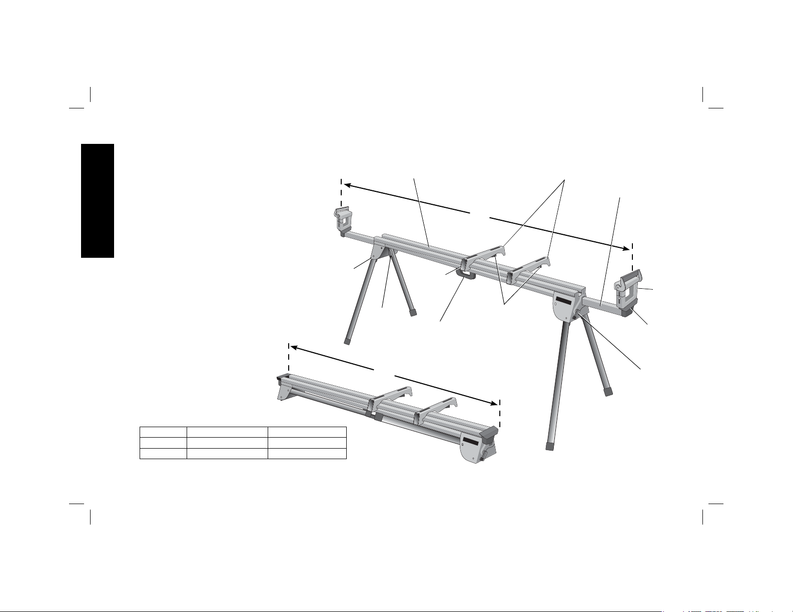
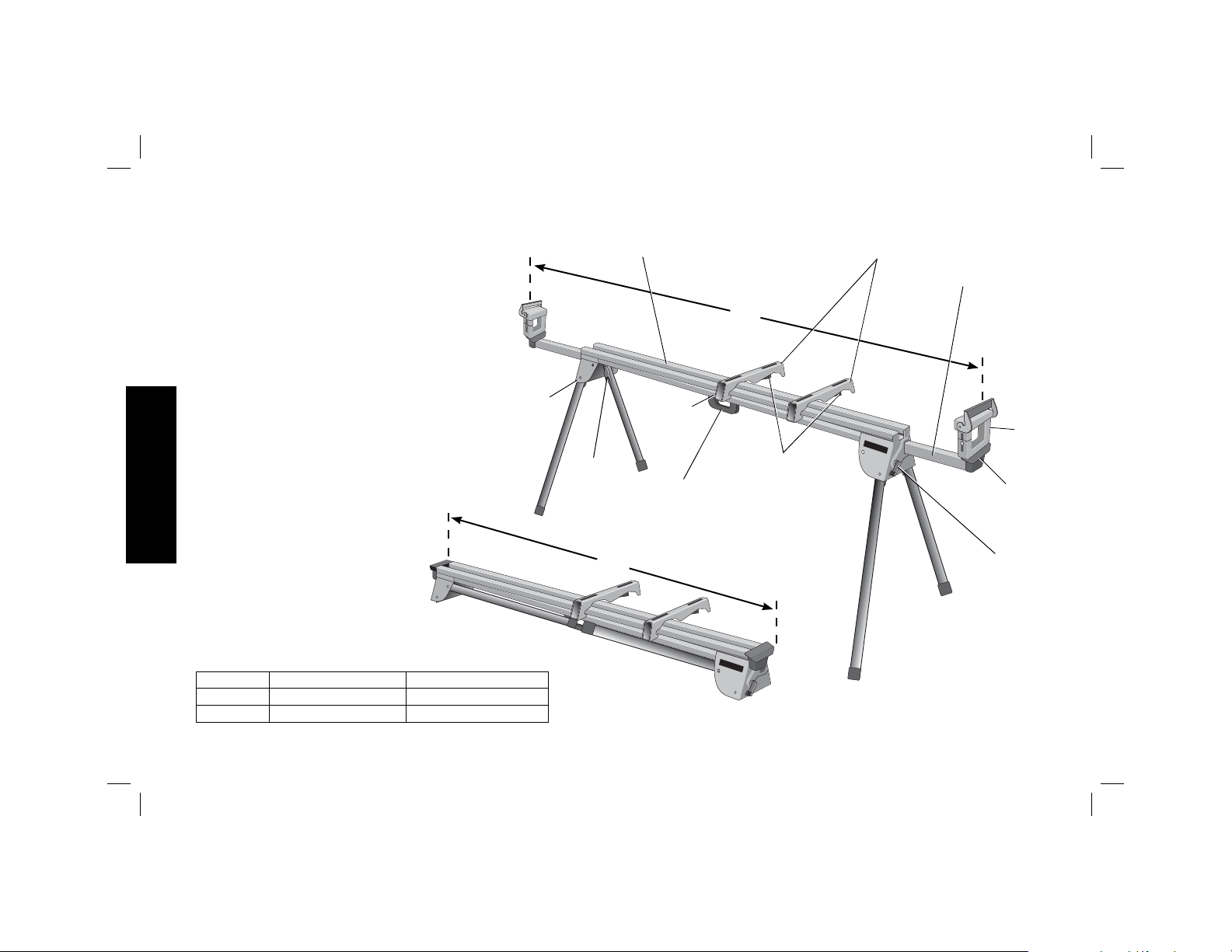
DWX723/DWX724 Miter Saw Stands
Components List
A. Beam
B. DW7231 Miter saw mounting brackets
C. Extension arm
D. DW7232 Work piece support and length
English
stop
E. Extension arm end cap
F. Extension arm lock lever
G. Release levers
H. Carry handle
I. Locking locator clip
J. Leg lock lever
K. Release button
12
DWX723 69.5"(1765.3 mm) 151" (3835.4 mm)
DWX724 43" (1092.2 mm) 100" (2540 mm)
FIG. 1
A
2
K
J
1
I
G
H
B
C
D
E
F
2
Page 3
Definitions: Safety Guidelines
The definitions below describe the level of severity
for each signal word. Please read the manual and pay
attention to these symbols.
DANGER: Indicates an imminently hazardous situation
which, if not avoided, will result in death or serious injury.
WARNING: Indicates a potentially hazardous situation
which, if not avoided, could result in death or serious injury.
CAUTION: Indicates a potentially hazardous situation
which, if not avoided, may result in minor or moderate
injury.
NOTICE: Indicates a practice not related to personal injury
which, if not avoided, may result in property damage.
IF YOU HAVE ANY QUESTIONS OR COMMENTS ABOUT THIS OR
ANY DEWALT TOOL, CALL US TOLL FREE AT: 1-800-4-DEWALT
(1-800-433-9258)
Miter Saw Stand with Folding Legs
DWX723/DWX724
This stand is designed for use with most miter saws. If you have
any problem with alignment or mounting, call 1-800-4-D
(1-800-433-9258).
WARNING: For your own safety, read the miter saw
instruction manual before using any accessory. Failure
to heed these warnings may result in personal injury and
serious damage to the miter saw and the accessory. When
servicing this tool, use only identical replacement parts.
EWALT
Carton Contents
1 Miter saw stand (DWX723 or DWX724)
2 Miter saw mounting brackets (DW7231)
2 Work piece support and length stops (DW7232)
1 Hardware bag
Tools Required
• Drill with 3/8" (9.5mm) drill bit (Not required for DEWALT Miter
Saws)
• Crosshead #2 screwdriver
• 1/2" (13mm) Wrench
Components (Fig. 1)
WARNING: Never modify the stand or any part of it. Damage or
personal injury could result.
Refer to Figure 1 for Components List.
General Safety Instructions for Miter Saw
Stands
WARNING: To reduce the risk of personal injury:
• ALWAYS use eye protection. All users and bystanders must
wear eye protection that conforms to ANSI Z87.1.
• ALWAYS check the stability of the miter saw stand and the miter
saw attached to it before putting the stand or the saw into use.
• DO NOT mount any power tool other than a miter saw to this
stand. Mounting other power tools to this stand could result in
severe personal injury.
• DO NOT exceed the weight this stand can hold. The main center
beam of the miter saw stand is designed to support 500 lbs.
(227kg.) safely in a work environment. It is unsafe to climb, sit or
stand on the stand.
English
1
Page 4
• Follow the mounting instructions carefully. Fasten the miter saw
to the saw mounting brackets securely as instructed.
• DO NOT modify or use stand for operations for which it is
unintended.
• DO NOT use the stand on uneven surfaces. The stand is
designed to be used on a flat, stable surface.
• DO NOT use on a slippery surface. The stand load capacity is
English
greatly reduced when used on slippery surfaces.
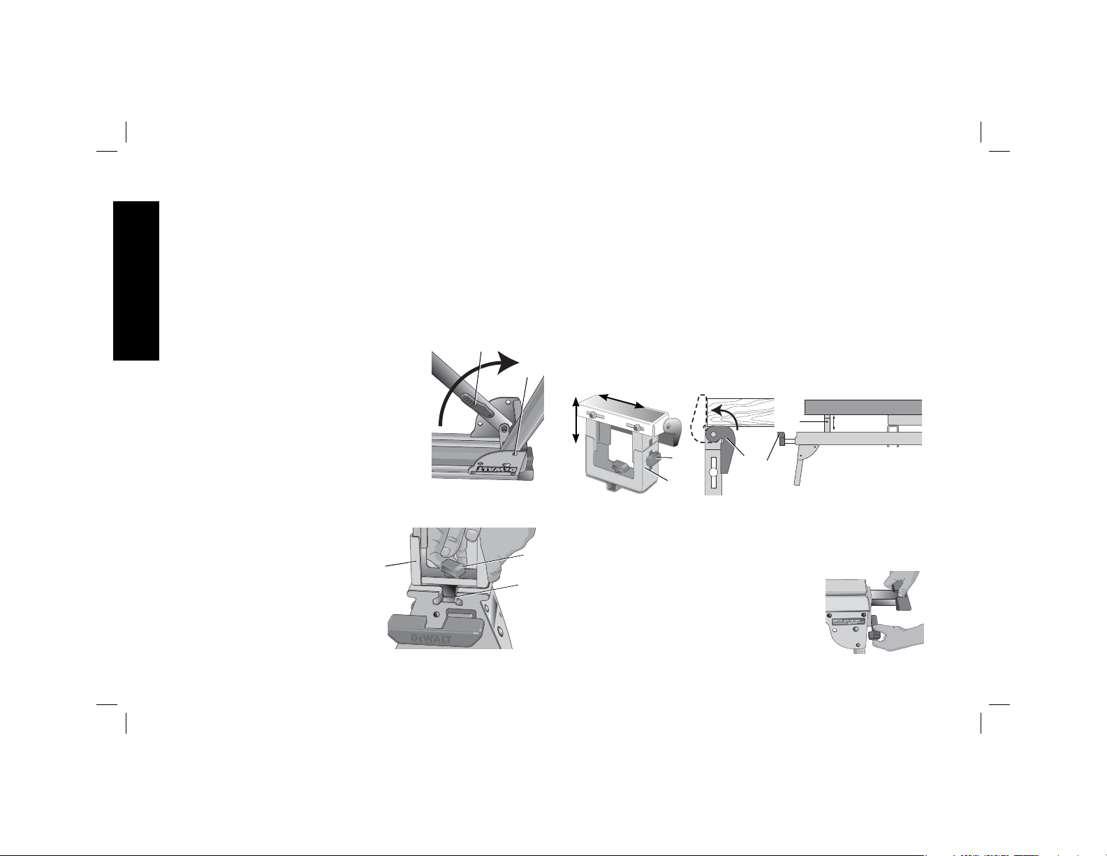
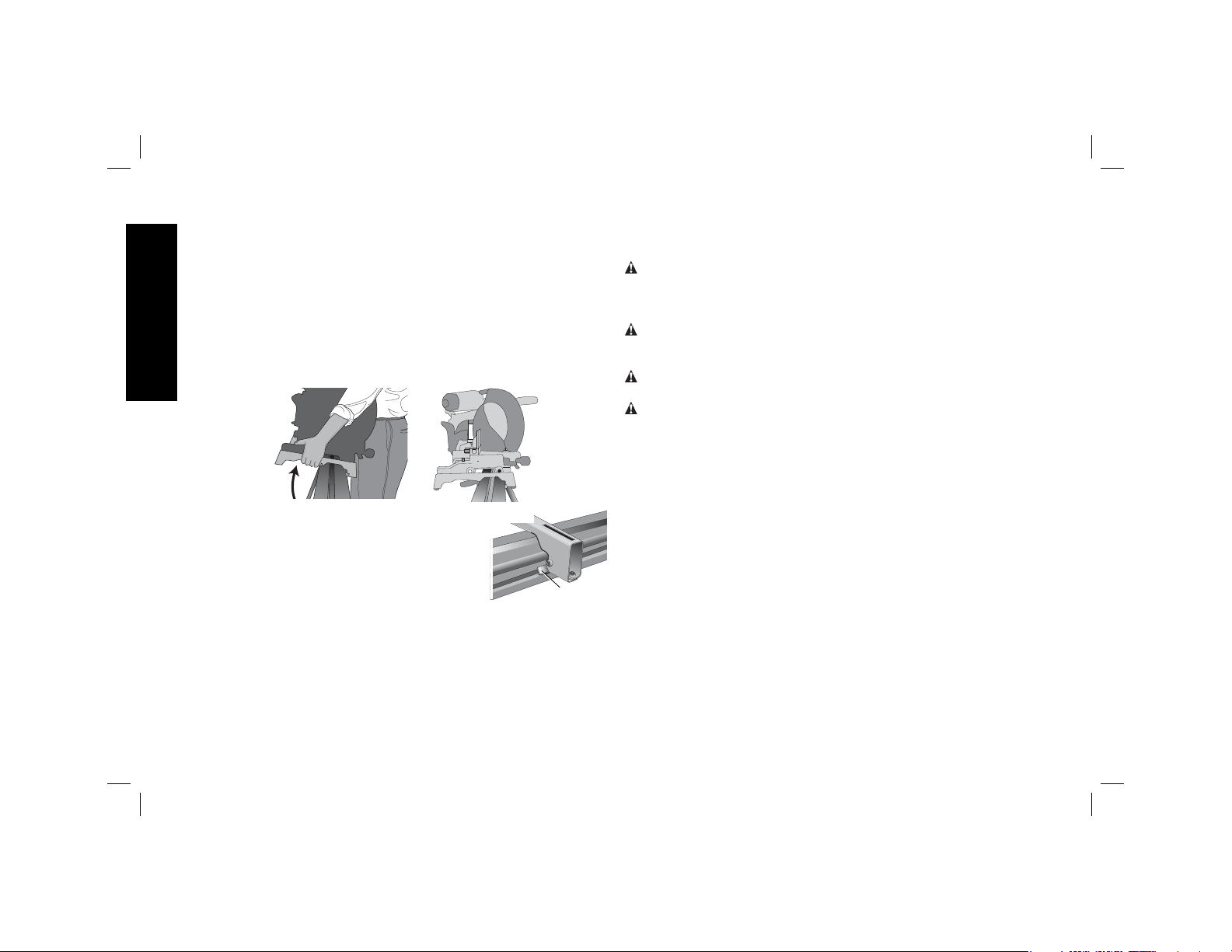
Preparation (Fig. 2)
1. Place the miter saw stand on the ground
with the folded legs facing up.
2. Depress the leg lock lever (J) or release
button (K) and pull leg up until the
locking pin clicks into the place. Repeat
on each leg.
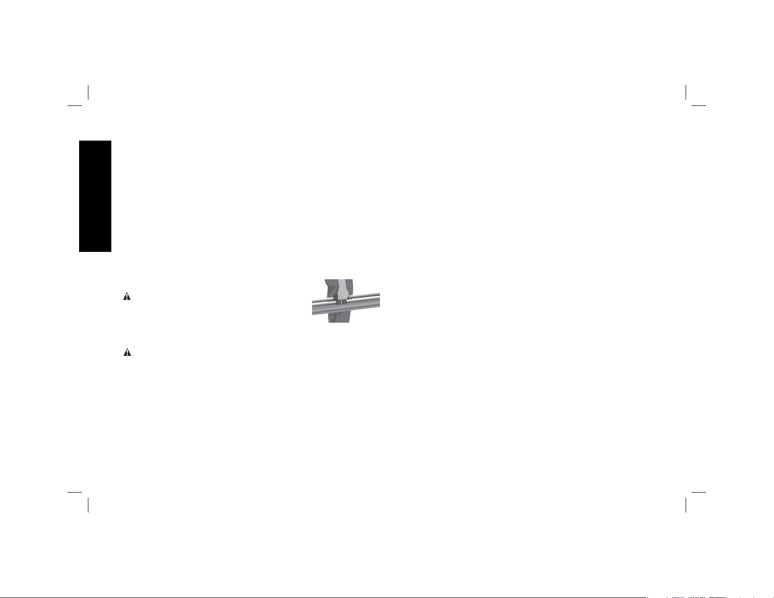
3. Lift the stand by the center beam and
place it in an upright position. The stand
should be stable and should not rock.
NOTE: Ensure all locking pins are engaged
and the legs are locked in place.
FIG. 2
J
ASSEMBLY
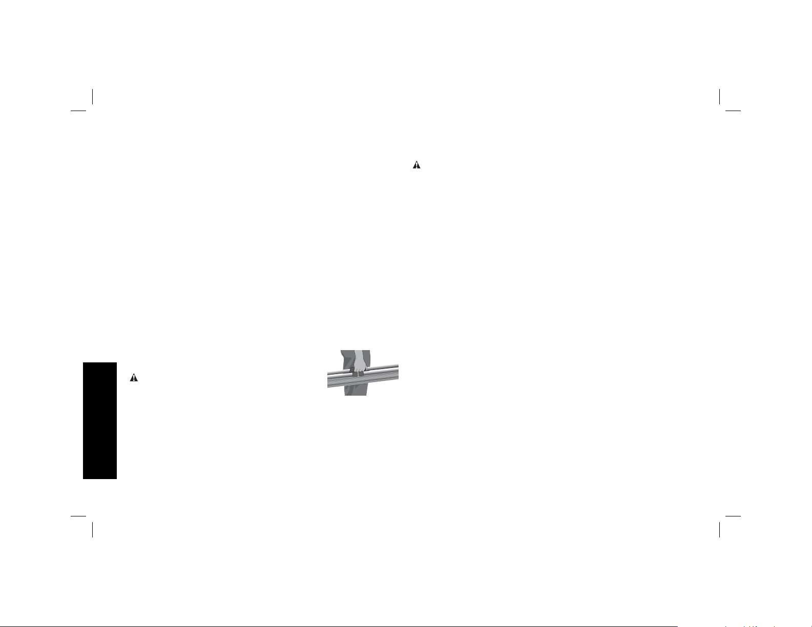
DW7232 Work Piece
FIG. 3
Support and Length
Stops (Fig. 3–4)
a. The work support/stop (D) has
a clamp (L) to capture the
beam and keep it from being
knocked off the beam by your
material. The knob (M) may be
D
locked by turning clockwise and the work support/stop is free
to be repositioned when the knob is turned counterclockwise.
Do not overtighten, firm pressure on the knob will hold the stop
in place.
b. Adjust the height of the work support/stop (D) by loosening the
knobs on both sides (N) and raise or lower the top surface to
align with a straight edge or level to the saw table. Tighten the
knobs.
NOTE: If the work support height adjustment slips down when
under a load, the weight limit of the work support has been
exceeded. This weight limit is limited by the tightness of the
K
M
L
height adjustment knobs. Do not tighten more than finger tight.
FIG. 4
D
N
D
c. The work support/stop (D) can also be installed in the end cap
(E) at the end of the extension arms.
d. The length stop (O) may be rotated up to serve as a length stop
or hold the end of long work pieces.
Adjustable Length
O
E
FIG. 5
Extension Arm
(Fig. 5)
To lengthen the support surface, turn the
extension arm lock lever counterclockwise
to release the extendable extension arm.
2
Page 5
Pull the extendable extension arm out to the desired length. Turn
the extension arm lock lever clockwise to lock.
DW7231 DEWALT Miter Saw Mounting
Method (Fig. 6, 7)
WARNING: To reduce the risk of injury, turn unit off,
disconnect machine from power source before assembling the
miter saw to the miter saw stand. An accidental start-up can
cause injury.
WARNING: Stability Hazard. You must use the Universal
Miter Saw Mounting Method when mounting a miter saw not
manufactured by D
WARNING: To reduce the risk of personal injury, be sure the
miter saw is fully anchored on the stand.
WARNING: For your own safety, read and understand the miter
saw instruction manual before using. Failure to heed these warnings
may result in personal injury and serious damage to the miter saw
and the accessory.
1. Place saw in operational position with blade facing you. Align
with label on the mounting bracket showing front.
2. Place a spacer, such as a 2 x 4, under one side of the miter saw
to hold the saw’s mounting feet above the work surface.
3. Hold a mounting bracket under the saw and feed a carriage bolt
(hardware bag) up through the bracket and the foot of the saw.
NOTE: See DW7231 Hardware Selection Chart for the correct
mounting hardware procedures for D
all instructions properly, otherwise the miter saw's table rotation
may be obstructed.
EWALT to this miter saw stand.
EWALT miter saws. Follow
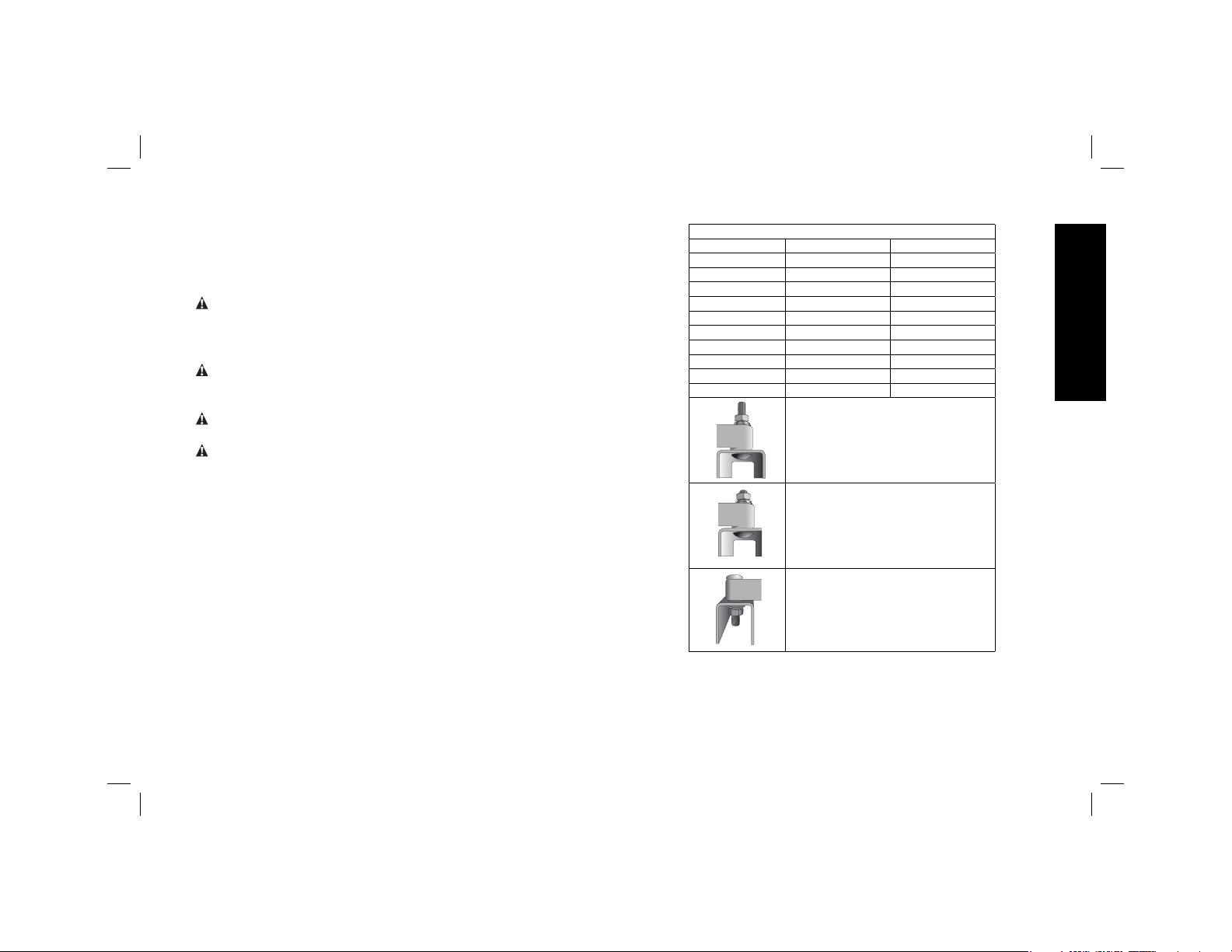
DW7231 HARDWARE SELECTION CHART
Left Side Right Side
DW703 1 1
DW705 1 1
DW706 1 1
DW708 1 2
DW712 1 2
DW713 1 1
DW715 1 1
DW716 1 1
DW717 2 1
DW718 3 2
1 = Long screw, Head on bottom
2 = Short screw, Head on bottom
3 = Long screw, Head on top
4. Once the carriage bolt (hardware bag) is installed per DW7231
Hardware Selection Chart, assemble a flat washer, lock
washer and nut onto the bolt. Tighten the bolts finger tight.
English
3
Page 6
5. Repeat procedure on the other end of the bracket.
6. Move the 2x4 to the other side of the saw to hold the other end
of the saw up in order to access the saw base.
7. Feed carriage bolts through the other bracket and the base of
the saw as before. Ensure both brackets are parallel to each
other.
8. To place the saw onto the stand, grasp and lift saw by mounting
English
bracket assembly by the release levers. These levers do not
lock the saw laterally in place but merely serve as a means of
mounting the saw to the beam.
FIG. 6
9. Approach the beam with saw/bracket
assembly tilting toward your body slightly.
Engage the concave front lip of the
mounting bracket with rounded edge of
beam. One of the brackets must engage
the locator clip (I) to prohibit lateral
movement of the saw during use.
10. When front edge of the beam and locking locator clip are
engaged, a slight downward pivot will allow secure engagement
of the release levers to the back of the beam. Rock the saw
gently on the brackets to verify locking in position.
11. Adjust the saw position as necessary to have the blade
perpendicular to the beam when in the 0 degree miter position.
12. Tighten the four nuts holding the saw to the brackets securely.
FIG. 7
DW7231 Universal Miter Saw Mounting
Method (Fig. 1, 7–9)
WARNING: To reduce the risk of injury, turn unit off,
disconnect machine from power source before assembling the
miter saw to the miter saw stand. An accidental start-up can
cause injury.
WARNING: Stability Hazard. You must use the plywood mounting
method described in the following instructions when mounting a
miter saw not manufactured by D
WARNING: To reduce the risk of personal injury, be sure the
miter saw is fully anchored on the stand.
WARNING: For your own safety, read and understand the miter
saw instruction manual before using. Failure to heed these warnings
may result in personal injury and serious damage to the miter saw
and the accessory.
NOTE: If you do not have a D
(19mm) plywood to mount your miter saw.
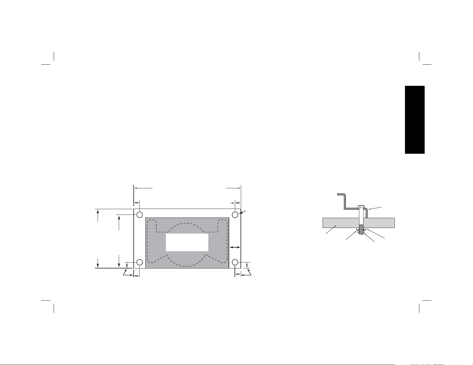
The plywood must be a minimum of 4" (101.6mm) wider than the
largest width of the miter saw base. The plywood should be at least
as deep as the smallest depth of the miter saw base or a minimum
of 16" (406.4mm) if miter saw base is smaller. Ensure the plywood
is square.
I
1. Once the Plywood size has been determined, drill 3/8" (9.5mm)
holes 1" (25.5 mm) from the front corners of plywood, 15"
(355mm) apart and 1" (25.5mm) from the sides.
2. Place DW7231 mounting brackets on the stand:
a. Grasp and squeeze release levers (G).
b. Engage the concave front lip of the mounting bracket with
rounded front edge of beam. One of the mounting brackets
must be engaged in the locator clip (I) to prohibit lateral
movement of the saw during use.
EWALT to this miter saw stand.
EWALT miter saw, you must use 3/4"
4
Page 7
3. When the front edge of beam and locator clip are engaged,
a slight downward pivot will allow secure engagement of the
release levers to the back of the beam. Follow same procedure
with second mounting bracket at the appropriate position on
the beam for the size of the plywood.
4. Place plywood onto mounting brackets and align drilled holes
with slots in mounting brackets. Refer to DW7231 Hardware
Selection Chart and use either Method 1 or 2 to secure plywood to mounting brackets.
5. Use 1/2" (13mm) wrench to tighten hardware.
6. The miter saw should be mounted to plywood using holes in
the miter saw base. The hardware size will be determined by
the holes in the miter saw base. Hardware should be 1-1/4"
(31.8 mm) longer than the maximum height of the miter saw
base at each mounting location.
FIG. 8
MINIMUM OF
16" (406.4mm)
MUST BE AT
LEAST AS DEEP
AS THE SAW
BEING MOUNT-
ING
15"
((381mm)
BOTH
SIDES
WIDTH OF SAW + 4" (101.6mm)
1" (25.5mm)
MOUNT MITER
SAW IN SHADED
AREA
1" (25.5mm)
a. Transfer location of mounting holes from miter saw base to
plywood.
b. Drill holes accordingly to the size of the hardware chosen.
NOTE: Hardware must be purchased to mount miter saw to
plywood. All purchased hardware should be a minimum of
Grade 5 or Class 8.8.
c. Secure miter saw to plywood as shown in Figure 9. Saw base
(P), 3/4" (19 mm) plywood (T), flat washer (Q), lock washer (S)
and nut (R).
NOTE: Ensure a flat washer (Q) is used between plywood (T)
and lock washer (S).
d. Tighten all hardware.
Carry Strap
If you purchase the carry strap accessory for DEWALT stands, use
the square hole in the metal end to mount the accessory.
FIG. 9
3/8" (9.5mm)
DIAMETER
HOLES, ALL
4 CORNERS
2" (50.8mm)
MINIMUM BOTH
SIDES
T
S
P
Q
R
English
1" (25.5mm)
1" (25.5mm)
5
Page 8
Locking Locator Clip (Fig. 1)
The locking locator clip (I) keeps the saw from sliding left or right
during cutting operations. To move the clip, remove saw/bracket
assembly, loosen the screw in the center of the clip, slide it to the
desired position and tighten the screw. You can then remount the
saw/bracket in the new location.
Removing the Saw
English
Once the miter saw is fastened to the brackets, it can be removed
by grasping the release levers, pulling up slightly to clear the beam
and can be set down on the non marring feet for transportation or
cleaning.
Carry Handle (Fig. 10)
A handle has been supplied to transport the
miter saw stand to and from the work site.
WARNING: To reduce the risk of personal
injury, DO NOT attempt to store or carry the
stand with the saw attached. Loss of control
may result.
FIG. 10
Accessories
WARNING: Since accessories, other than those offered by
D
EWALT, have not been tested with this product, use of such
accessories with this tool could be hazardous. To reduce the risk of
injury, do not create unstable conditions and use only with D
miter saw stands.
COMPATIBLE PRODUCTS
DW7231 – Miter saw mounting brackets
DW7232 – Work piece support and length stops
DW7029 – Wide work piece support and length stops
EWALT
DW7027 – Roller work piece support
DW7028 – Extension support
DW7026 – Carry strap
Recommended accessories for use with your tool are available at
extra cost from your local dealer or authorized service center. If you
need assistance in locating any accessory, please contact D
Industrial Tool Co., 701 East Joppa Road, Baltimore, MD 21286,
call 1-800-4-D
dewalt.com.
EWALT (1-800-433-9258) or visit our website www.
EWALT
Repairs
To assure product SAFETY and RELIABILITY, repairs, maintenance
and adjustments should be performed by a D
center, a D
service personnel. Always use identical replacement parts.
EWALT authorized service center or other qualified
EWALT factory service
Three Year Limited Warranty
DEWALT will repair, without charge, any defects due to faulty
materials or workmanship for three years from the date of purchase.
This warranty does not cover part failure due to normal wear or tool
abuse. For further detail of warranty coverage and warranty repair
information, visit www.dewalt.com or call 1-800-4-D
433-9258). This warranty does not apply to accessories or damage
caused where repairs have been made or attempted by others. This
warranty gives you specific legal rights and you may have other
rights which vary in certain states or provinces.
In addition to the warranty, D
1 YEAR FREE SERVICE
EWALT will maintain the tool and replace worn parts caused by
D
normal use, for free, any time during the first year after purchase.
EWALT tools are covered by our:
EWALT (1-800-
6
Page 9
90 DAY MONEY BACK GUARANTEE
If you are not completely satisfied with the performance of your
D
EWALT Power Tool, Laser, or Nailer for any reason, you can return
it within 90 days from the date of purchase with a receipt for a full
refund – no questions asked.
LATIN AMERICA: This warranty does not apply to products sold
in Latin America. For products sold in Latin America, see country
specific warranty information contained either in the packaging, call
the local company or see website for warranty information.
FREE WARNING LABEL REPLACEMENT: If your warning labels
become illegible or are missing, call 1-800-4-D
EWALT (1-800-433-
9258) for a free replacement.
English
7
Page 10
Établis de scie à onglet DWX723/DWX724
Description
A. Longeron
B. Dispositifs de fixation de scie à
onglet DW7231
C. Rallonge
D. Support de pièce et butée de
longueur DW7232
E. Embout de rallonge
F. Levier de verrouillage de la rallonge
G. Leviers de déverrouillage
H. Poignée de transport
I. Agrafe de positionnement
verrouillable
J. Levier de verrouillage de pied
K. Bouton de libération
Français
FIG. 1
K
A
2
I
J
H
G
B
C
D
E
12
DWX723 1765,3 mm (69,5 po) 3835,4 mm (151 po)
DWX724 1092,2 mm (43 po) 2540 mm (100 po)
1
8
F
Page 11

Définitions: lignes directrices en
matière de sécurité
Les définitions ci-dessous décrivent le niveau de danger pour
chaque mot-indicateur employé. Lire le mode d’emploi et
porter une attention particulière à ces symboles.
DANGER: indique une situation dangereuse imminente qui,
si elle n’est pas évitée, entraînera la mort ou des blessures
graves.
AVERTISSEMENT : indique une situation potentiellement
dangereuse qui, si elle n’est pas évitée, pourrait entraîner la
mort ou des blessures graves.
ATTENTION : indique une situation potentiellement
dangereuse qui, si elle n’est pas évitée, pourrait entraîner des
blessures légères ou modérées.
AVIS : indique une pratique ne posant aucun risque de
dommages corporels mais qui par contre, si rien n’est fait
pour l’éviter, pourrait poser des risques de dommages
matériels.
EN CAS DE QUESTIONS OU DE COMMENTAIRES SUR CET
E
OUTIL OU SUR TOUT AUTRE OUTIL D
NOUS SANS FRAIS AU NUMÉRO SUIVANT : 1 (800) 4-D
(1 (800) 433-9258)
WALT, APPELEZ-
E
WALT
Support de scie à onglets avec pattes
pliantes DWX723/DWX724
Ce support est destiné à être utilisé avec la plupart des modèles
de scie à onglets. Si on éprouve des difficultés au niveau de son
alignement ou de son montage, composer le 1-800-4-D
(1 800 433-9258).
EWALT
AVERTISSEMENT: pour votre sécurité, lire le manuel
de l’utilisateur de la scie à onglet avant l’utilisation de
tout accessoire. Tout manquement à ces avertissements
augmente les risques de dommages corporels, et les risques
de sérieusement endommager la scie à onglet et ses
accessoires. Lors de l’entretien de cet appareil, utiliser
seulement des pièces de rechange identiques.
Contenu du carton
1 Établi de scie à onglet (DWX723 ou DWX724)
2 Dispositifs de fixation de scie à onglet (DW7231)
2 Support de pièce et butées de longueur (DW7232)
1 Sac de quincaillerie
Outils nécessaires
• Perceuse munie d’une mèche de 9,5mm (3/8po) (inutile avec
les scies à onglet D
• Tournevis en croix #2
• Clé de 13mm (1/2po)
EWALT)
Description (Fig.1)
AVERTISSEMENT : ne jamais modifier l’outil ni aucun de ses
composants, car il y a risques de dommages corporels ou matériels.
Se reporter à la figure1 pour la Description de l’établi.
Consignes générales de sécurité relatives
aux établis de scie à onglet
AVERTISSEMENT : pour réduire tout risque de dommages
corporels:
• Porter SYSTÉMATIQUEMENT une protection oculaire. Tout
utilisateur ou individu présent doit porter une protection oculaire
homologuée ANSI Z87.1.
Français
9
Page 12

• Vérifier SYSTÉMATIQUEMENT la stabilité de l’établi de scie à
onglet et celle de la scie à onglet qui lui est rattachée, avant toute
utilisation de l’établi et de la scie.
• N’installer AUCUN outil électrique autre qu’une scie à onglet
sur cet établi. Le fait de monter tout autre outil sur cet établi
augmente les risques de dommages corporels.
• NE PAS excéder le poids maximum recommandé pour ce
support. Le longeron central principal du support de scie à
onglet a été conçu pour supporter en toute sécurité 227 kg
(500lb).
• Suivre soigneusement les instructions d’installation. Arrimer
soigneusement la scie à onglet aux dispositifs de fixation de la
scie conformément aux instructions.
• NE PAS modifier ou utiliser le socle pour des fonctions
auxquelles il n’est pas conçu.
• NE PAS utiliser le socle sur une surface inégale. Il est conçu pour
une utilisation sur une surface plane et stable.
Français
• NE PAS l’utiliser sur une surface glissante. La capacité de
charge de l’établi est grandement réduite lorsqu’utilisé sur une
surface glissante.
Préparation (Fig.2)
1. Placez l’établi de scie à onglet sur le sol
avec ses pieds repliés sur le dessus.
2. Appuyez sur le levier de verrouillage du
pied (J) ou le bouton de libération (K) et
tirez le pied vers le haut jusqu’à ce que
la goupille de verrouillage s’enclenche
en place. Répétez l’opération pour
l’autre pied.
FIG. 2
J
3. Soulevez l’établi par le centre du longeron et mettez-le en
station verticale. L’établi devrait être stable et fixe.
REMARQUE: veiller à ce que les goupilles de verrouillage soient
bien enclenchées et les pieds verrouillés en place.
MONTAGE
Support de pièce et butées de longueur
(DW7232) (Fig.3 à 4)
a. Le dispositif support de pièce/
butée (D) est équipé d’une
fixation (L) pour l’arrimer au
longeron et l’empêcher d’être
éjecté du longeron par le
matériau. Le bouton (M) peut
être verrouillé en tournant vers
la droite, et le dispositif butée/
support de pièce peut être
repositionné facilement en
tournant le bouton vers la gauche. Évitez de trop serrer, une
pression ferme sur le bouton suffira pour maintenir la butée en
place.
b. Ajustez la hauteur du support de pièce/butée (D) en desserrant
les boutons de chaque côté (N), et élevez ou abaissez la surface
K
supérieure pour l’aligner avec un guide de chant ou la mettre de
niveau avec la table de scie. Resserrez les boutons.
REMARQUE: si le réglage de la hauteur du support de pièce
bouge sous la charge, la limite de poids du support de pièce
aura été excédée. La limite de poids est fonction du serrage des
boutons de réglage de hauteur. Ne serrez qu’avec les doigts.
FIG. 3
D
M
L
10
Page 13

FIG. 4
D
N
D
c. Le dispositif support de pièce/butée (D) peut aussi être installé
sur l’embout (E) à l’extrémité des rallonges.
d. La butée de longueur (O) peut être tournée vers le haut pour
servir de butée de longueur ou pour maintenir l’extrémité de
longues pièces.
Rallonge réglage (Fig.5)
Pour rallonger la surface de l’établi, tournez
le levier de verrouillage de la rallonge vers la
gauche pour libérer la rallonge extensible.
Étirez la rallonge extensible sur la longueur
désirée. Refermez le levier de verrouillage
de la rallonge vers la droite.
O
E
FIG. 5
Méthode d’installation de
la scie à onglet DEWALT DW7231
(Fig.6, 7)
AVERTISSEMENT : pour réduire tout risque de dommages
corporels, arrêter et débrancher la scie à onglet du secteur avant
de la monter sur le support de scie à onglet. Tout démarrage
accidentel comporte des risques de dommages corporels.
AVERTISSEMENT: risques d’instabilité. Pour installer une scie
à onglet non fabriquée par D
suivre la Méthode d’installation de scie à onglet universelle.
AVERTISSEMENT : pour réduire tout risque de dommages
corporels, s’assurer que la scie à onglet est fermement arrimée au
support.
AVERTISSEMENT : pour votre sécurité, lire et comprendre le
manuel de l’utilisateur de la scie à onglet avant toute utilisation.
Tout manquement à ces avertissements augmente les risques de
dommages corporels, et les risques de sérieusement endommager
la scie à onglet et ses accessoires.
1. Installez la scie en position opérationnelle avec la lame face à
vous. Alignez-la sur l’étiquette de la ferrure affichant «avant».
2. Placez une barre d’écartement, comme un colombage, sous
l’un des côtés de la scie à onglet pour surélever les pieds de
montage de la scie au-dessus de la surface de travail.
3. Maintenez une ferrure sous la scie et insérez un boulon de
carrosserie (sac pour quincaillerie) au travers de la ferrure et du
pied de scie.
REMARQUE: consulter le Tableau de sélection de matériel
DW7231 pour connaître la procédure correcte d’installation
des scies à onglet D
directives, pour éviter d’entraver la rotation de la table de scie à
onglet.
EWALT sur cet établi de scie à onglet,
EWALT. Suivre soigneusement toutes les
Français
11
Page 14
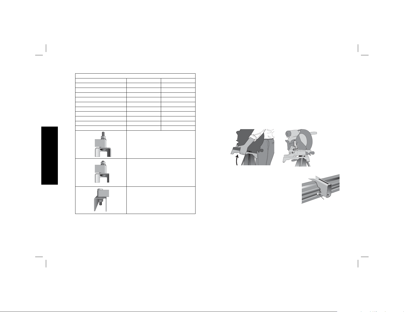
TABLEAU DE SÉLECTION DE MATÉRIEL DW7231
Côté gauche Côté droit
DW703 1 1
DW705 1 1
DW706 1 1
DW708 1 2
DW712 1 2
DW713 1 1
DW715 1 1
DW716 1 1
DW717 2 1
DW718 3 2
1 = vis longue, tête dessous
Français
2 = vis courte, tête dessous
3 = vis longue, tête dessus
4. Une fois le boulon de carrosserie (sac de quincaillerie) installé
conformément au Tableau de sélection de matériel DW7231,
insérez une rondelle plate, une rondelle de blocage et un écrou
sur le boulon. Resserrez à fond manuellement les boulons.
5. Répétez la procédure à l’autre bout de la ferrure.
6. Déplacez le colombage de l’autre côté de la scie pour le
soutenir et avoir accès à la base de la scie.
7. Insérez les boulons au travers de l’autre ferrure et de la base de
la scie comme indiqué ci-dessus. Assurez-vous que les ferrures
sont bien parallèles.
8. Pour installer la scie sur le support, attrapez et soulevez la scie
par les leviers de dégagement du dispositif de ferrure. Ces
leviers ne servent pas à verrouiller la scie en place latéralement,
mais seulement à installer la scie sur le longeron.
FIG. 6
9. Approchez-vous du longeron avec le
FIG. 7
dispositif scie/ferrure légèrement incliné
vers votre corps. Engagez la lèvre avant
concave des ferrures sur le rebord arrondi
du longeron. L’une des ferrures doit
s’enclencher dans l’agrafe de
I
positionnement (I) pour éviter tout
mouvement latéral de la scie pendant son utilisation.
10. Lorsque le bord avant du longeron et l’agrafe de positionnement
sont verrouillés, un léger pivotement vers le bas permettra
d’engager les leviers postérieurs à l’arrière du longeron. Essayez
de remuer légèrement la scie sur les ferrures pour vérifier qu’elle
est bien verrouillée en place.
12
Page 15

11. Ajustez la position de la scie comme nécessaire de façon à ce
que la lame soit perpendiculaire au longeron en position de zéro
degré d’onglet.
12. Resserrez les quatre écrous arrimant la scie aux ferrures.
Méthode d’installation de scie à onglet
universelle DW7231 (Fig.1, 7 à 9)
AVERTISSEMENT : pour réduire tout risque de dommages
corporels, arrêter et débrancher la scie à onglet du secteur
avant de la monter sur le support de scie à onglet. Tout
démarrage accidentel comporte des risques de dommages
corporels.
AVERTISSEMENT: risques d’instabilité. Pour installer une scie
à onglet non fabriquée par D
suivre la méthode d’installation sur contreplaqué suivante.
AVERTISSEMENT : pour réduire tout risque de dommages
corporels, s’assurer que la scie à onglet est fermement arrimée au
support.
AVERTISSEMENT : pour votre sécurité, lire et comprendre le
manuel de l’utilisateur de la scie à onglet avant toute utilisation.
Tout manquement à ces avertissements augmente les risques de
dommages corporels, et les risques d’endommager sérieusement
la scie à onglet et ses accessoires.
REMARQUE: si votre scie n’est pas une scie à onglet D
morceau de contreplaqué de 19mm (3/4po) sera nécessaire pour
y fixer la scie à onglet.
Le contreplaqué doit dépasser d’au moins 101,6mm (4po) de la
partie la plus large de la base de la scie à onglet. Le contreplaqué
doit être au moins aussi profond que la profondeur minimale de
la base de la scie à onglet, ou mesurer au minimum 406,4 mm
(16po) si la base de scie à onglet est plus petite. Veillez à ce que le
contreplaqué soit bien carré.
EWALT sur cet établi de scie à onglet,
EWALT, un
1. Une fois la taille du contreplaqué déterminée, percez des
trous de 9,5mm (3/8po) à 25,5mm (1po) des coins avant du
contreplaqué, tous les 355mm (15po) et à 25,5mm (1po) des
bords.
2. Placez les dispositifs de fixation DW7231 sur l’établi:
a. Attrapez et appuyez sur les leviers de déverrouillage (G).
b. Engagez la lèvre avant concave du dispositif de fixation sur
le rebord arrondi avant du longeron. L’un des dispositifs de
fixation doit s’enclencher dans l’agrafe de positionnement (I)
pour éviter tout mouvement latéral de la scie pendant son
utilisation.
3. Lorsque le bord avant du longeron et l’agrafe de positionnement
sont verrouillés, un léger pivotement vers le bas permettra le
verrouillage des leviers de déverrouillage à l’arrière du longeron.
Suivez la même procédure avec le second dispositif de fixation,
sur la position appropriée sur le longeron suivant la taille du
contreplaqué.
4. Placez le contreplaqué sur les dispositifs de fixation et alignez
les trous percés sur les orifices des dispositifs de fixation.
Reportez-vous au Tableau de sélection de matériel DW7231
et utilisez la méthode1 ou 2 pour arrimer le contreplaqué aux
dispositifs de fixation.
5. Utilisez la clé de 13mm (1/2 po) pour resserrer la quincaillerie.
6. La scie à onglet doit être montée sur le contreplaqué à l’aide
des trous sur la base de la scie à onglet. La taille du matériel
utilisé sera déterminée par les trous de la base de la scie à
onglet. La quincaillerie devrait dépasser d’au moins 31,8mm
(1-1/4po) de la hauteur maximale de la base de la scie à onglet
sur chaque point d’assemblage.
Français
13
Page 16

a. Marquez l’emplacement des trous de montage de la base de
la scie à onglet sur le contreplaqué.
b. Percez les trous conformément à la taille de la quincaillerie
choisie.
REMARQUE : la quincaillerie nécessaire à l’installation de la
scie à onglet sur le contreplaqué est vendue séparément. Toute
quincaillerie utilisée doit être d’un grade 5 ou de classe 8.8
minimum.
c. Arrimez la scie à onglet au contreplaqué, comme illustré en
figure9. Base de la scie (P), contreplaqué 19 mm (3/4po) (T),
rondelle plate (Q), rondelle de blocage (S) et écrou (R).
REMARQUE : veillez à utiliser une rondelle plate (Q) entre le
contreplaqué (T) et la rondelle de blocage (S).
d. Resserrez l’ensemble de la quincaillerie.
Courroie de transport
Si vous avez acheté une courroie de transport pour établis
D
EWALT, veuillez utiliser le petit trou carré à l’extrémité du métal
pour installer cet accessoire.
Agrafe de fixation du positionneur (Fig. 1)
L’agrafe de fixation du positionneur (I) empêche la scie de glisser
vers la gauche ou vers la droite durant la coupe. Pour déplacer
l’agrafe, retirer la scie et ses ferrures, desserrer la vis située au
centre de l’agrafe et faire glisser celle-ci jusqu’à la position voulue;
resserrer la vis. Réinstaller la scie (avec les ferrures) à la nouvelle
position.
Français
406,4mm
(16po)
MINIMUM
DOIT ÊTRE
AUSSI LARGE
QUE LA BASE
DE LA SCIE
INSTALLÉE
25,5mm (1po)
FIG. 8
381mm
(15po) DE
CHAQUE
CÔTÉ
LARGEUR DE SCIE + 101,6mm (4po)
25,5mm (1po)
MONTAGE DE LA SCIE DE
BÂTI DANS LE
SECTEUR OMBRAGÉ
25,5mm (1po)
DIAMÈTRE DE
TROUS: 9,5mm
(3/8po), DANS
4 COINS
MINIMUM DE
50,8mm (2po) DE
CHAQUE CÔTÉ
25,5mm (1po)
14
LES
FIG. 9
T
P
S
Q
R
Page 17

Retrait de la scie
Une fois la scie à onglet arrimée aux dispositifs de fixation, elle peut
être retirée en attrapant les leviers de déverrouillage, et en tirant
légèrement pour libérer le longeron. Elle peut alors être posée sur
ses patins anti-rayures pour transport et entretien.
Poignée de transport (Fig.10)
Une poignée est fournie pour transporter
l’établi de scie à onglet sur les chantiers.
AVERTISSEMENT : pour réduire tout
risque de dommages corporels, NE PAS
tenter d’entreposer ou transporter l’établi
avec la scie rattachée, pour éviter tout
risque d’en perdre le contrôle.
FIG. 10
Accessoires
AVERTISSEMENT : comme les accessoires autres que ceux
offerts par D
utilisation avec cet appareil pourrait comporter un danger. Pour
réduire tout risque de dommages corporels, éviter toute condition
précaire et utiliser seulement des établis de scies à onglet D
PRODUITS COMPATIBLES
DW7231 – Dispositifs de fixation de scie à onglet
DW7232 – Support de pièce et butées de longueur
DW7029 – Support de pièce large et butées de longueur
DW7027 – Support de pièce à rouleaux
DW7028 – Support extensible
DW7026 – Courroie de transport
EWALT n’ont pas été testés avec ce produit, leur
EWALT.
Les accessoires recommandés pour votre outil peuvent être achetés
auprès du distributeur local ou d’un centre de réparation agréé.
Si vous avez besoin d’assistance pour trouver un accessoire pour
votre outil, veuillez contacter D
Joppa Road, Baltimore, MD 21286, États-Unis, composer le 1(800)
4-D
EWALT (1-800-433-9258) ou visiter notre site Web à www.dewalt.
com.
Réparations
Pour assurer la SÉCURITÉ et la FIABILITÉ du produit, les réparations,
l’entretien et les réglages doivent être réalisés par un centre de
réparation en usine D
D
EWALT ou par un personnel de réparation professionnel. Toujours
utiliser des pièces de rechange identiques.
EWALT Industrial Tool Co., 701 East
EWALT, un centre de réparation autorisé
Garantie limitée trois ans
DEWALT réparera gratuitement tous les problèmes dus à des
défauts de matériau ou de fabrication pendant trois ans à compter
de la date d’achat. Cette garantie ne couvre pas des défaillances
de pièce dues à une usure normale ou à une mauvaise utilisation de
l’outil. Pour plus de détails relatifs à la couverture de la garantie et
aux réparations sous garantie, visiter le site Web www.dewalt.com
ou composer le 1-800-4-D
ne s’applique pas aux accessoires ni aux dommages causés par
des réparations réalisées ou tentées par des tiers. Cette garantie
vous accorde des droits légaux spécifiques et il est possible que
vous ayez d’autres droits qui varient d’un État ou d’une province à
l’autre.
EWALT (1-800-433-9258). Cette garantie
Français
15
Page 18

En plus de la garantie, les outils DEWALT sont couverts par notre :
SERVICE D’ENTRETIEN GRATUIT DE 1 AN
EWALT entretiendra l’outil et remplacera les pièces usées par une
D
utilisation normale et ce, gratuitement, à tout instant pendant la
première année à compter de la date d’achat.
GARANTIE DE REMBOURSEMENT DE 90 JOURS
Si vous n’êtes pas entièrement satisfait des performances de votre
outil électrique, laser ou de votre marteau-cloueur D
EWALT pour
quelque raison que ce soit, vous pouvez le retourner accompagné
d’un reçu dans les 90 jours suivant la date d’achat et nous vous
rembourserons entièrement - sans poser de questions.
AMÉRIQUE LATINE : cette garantie ne s’applique pas aux produits
vendus en Amérique latine. Pour ceux-ci, veuillez consulter les
informations relatives à la garantie spécifique présente dans
l’emballage, appeler l’entreprise locale ou consulter le site Web
pour les informations relatives à cette garantie.
Français
REMPLACEMENT GRATUIT DES ÉTIQUETTES
D’AVERTISSEMENT : si les étiquettes d’avertissement deviennent
illisibles ou sont manquantes, composer le 1-800-4-D
EWALT
(1-800-433-9258) pour en obtenir le remplacement gratuit.
16
Page 19

DWX723/DWX724 Soportes para ingleteadora
Lista de componentes
FIG. 1
A. Viga
B. DW7231 Soportes de montaje para
ingleteadora
C. Brazo de extensión
D. DW7232 Soporte para pieza a trabajar
y tope de longitud
E. Tapa superior del brazo de extensión
F. Palanca de bloqueo del brazo de
extensión
G. Palancas de liberación
K
H. Asa
I. Gancho para ubicación de bloqueo
J. Palanca de seguro para la pata
K. Botón de destrabado
12
DWX723 1765,3 mm (69,5 pulg.) 3835,4 mm (151 pulg.)
DWX724 1092,2 mm (43 pulg.) 2540 mm (100 pulg.)
A
2
I
J
H
1
G
B
C
D
E
F
Español
17
Page 20

Definiciones: Normas de seguridad
Las siguientes definiciones describen el nivel de gravedad de
cada palabra de señal. Lea el manual y preste atención a estos
símbolos.
PELIGRO: Indica una situación de peligro inminente que, si no
se evita, provocará la muerte o lesiones graves.
ADVERTENCIA: Indica una situación de peligro potencial
que, si no se evita, podría provocar la muerte o lesiones
graves.
ATENCIÓN: Indica una situación de peligro potencial que,
si no se evita, posiblemente provocaría lesiones leves o
moderadas.
AVISO: Se refiere a una práctica no relacionada a lesiones
corporales que de no evitarse puede resultar en daños a la
propiedad.
SI TIENE ALGUNA DUDA O ALGÚN COMENTARIO SOBRE ÉSTA
U OTRA HERRAMIENTA D
GRATUITO: 1-800-4-D
EWALT, LLÁMENOS AL NÚMERO
EWALT (1-800-433-9258)
Base para ingleteadora
DWX723/DWX724
Esta base está diseñada para usarse con la mayoría de las
ingleteadoras. Si tiene algún problema con la alineación o el
montaje, llame al 1-800-4-D
EWALT.
Español
ADVERTENCIA : Para su seguridad, lea el manual de
instrucciones de la ingleteadora antes de utilizar
cualquier accesorio. De no seguir estas advertencias podrían
producirse lesiones corporales y graves daños a la
ingleteadora y al accesorio. Cuando realice el mantenimiento
de esta herramienta, utilice únicamente repuestos originales.
Contenido de la caja
1 Soporte para ingleteadora (DWX723 ó DWX724)
2 Soportes de montaje para Ingleteadora (DW7231)
2 Soporte para pieza a trabajar y topes de de longitud (DW7232)
1 Bolsa de accesorios de montaje
Herramientas requeridas
• Taladro con una broca de 9,5mm (3/8 pulg.) (No es necesario
con las ingleteadoras de D
• Destornillador con cabeza de estrella #2
• Llave de 13mm (1/2 pulg.)
EWALT)
Componentes (Fig. 1)
ADVERTENCIA: Nunca modifique el soporte, ni tampoco
ninguna de sus partes. Podría producir lesiones corporales o daños.
Remítase a la Figura 1 para obtener la Lista de componentes.
Instrucciones de seguridad generales
para soportes para ingleteadora
ADVERTENCIA: Para reducir el riesgo de lesión personal:
• SIEMPRE use protección ocular. Todos los usuarios y
transeúntes deben de usar protección ocular conforme a
ANSI Z87.1.
18
Page 21

• SIEMPRE verifique la estabilidad del soporte de la ingleteadora
y de la ingleteadora sujeta al mismo antes de utilizar el soporte o
la sierra.
• NO monte ninguna herramienta eléctrica distinta de una
ingleteadora sobre este soporte. El montaje de otros herramientas
eléctricas sobre este soporte podría tener como consecuencia
lesiones corporales graves.
• NO exceda el peso que el pie puede aguantar. La viga central
principal de la ingleteadora ha sido diseñada para aguantar
227kg (500 lbs.) sin peligro alguno.
• Siga detenidamente las instrucciones de montaje. Sujete bien
la ingleteadora a los soportes de montaje de la sierra, como se
indica.
• NO modifique la base ni la utilice para otras tareas que no sean
aquéllas para la que fue diseñada.
• NO utilice la base sobre superficies desniveladas. La base fue
diseñada para utilizarse sobre una superficie plana y estable.
• NO lo use sobre una superficie resbalosa. La capacidad de carga
del soporte se reduce considerablemente cuando se usa sobre
superficies resbalosas.
Preparación (Fig. 2)
1. Coloque el soporte de la ingleteadora
sobre el piso con las patas dobladas
mirando hacia abajo.
2. Presione la palanca de seguro para la
pata (J) o el botón de liberación (K) y
tire de la pata hacia arriba hasta que el
pasador de seguridad haga clic en su
lugar. Repita para cada pata.
FIG. 2
J
K
3. Levante el soporte por la viga central y colóquelo en una
posición vertical. El soporte debería quedar estable y no se
debería mover.
NOTA: Asegúrese que todos los pasadores de seguridad estén
encajados y que todas las piernas estén aseguradas en su lugar.
ENSAMBLAJE
DW7232 Soporte para pieza a trabajar y
topes de longitud (Fig. 3–4)
a. El soporte para el trabajo/tope
(D) tiene una abrazadera (L)
para asegurar la viga y evitar
que su material la derribe. La
perilla (M) puede ser bloqueada
girándola en sentido horario y
se puede reposicionar
libremente el soporte/tope del
trabajo cuando se gira la perilla
en sentido antihorario. No apriete excesivamente; la presión
firme sobre la perilla mantendrá el tope en su lugar.
b. Ajuste la altura del soporte/tope del trabajo (D) aflojando las
perillas a ambos lados (N) y levantando o bajando la superficie
superior para alinear con un borde recto o nivel con respecto a
la mesa de la sierra. Apriete las perillas.
NOTA: Si el ajuste de altura del soporte del trabajo se desliza
hacia abajo cuando está bajo carga, se ha excedido el límite de
peso del soporte del trabajo. Este límite de peso se ve limitado
por la tirantez de las perillas de ajuste de altura. No apriete más
de lo que sea posible con los dedos.
FIG. 3
D
M
L
Español
19
Page 22

FIG. 4
D
N
D
c. El soporte/tope del trabajo (D) también puede ser instalado en
la tapa superior (E) al extremo de los brazos de extensión.
d. El tope de longitud (O) puede ser girado para servir como un
tope de longitud o para sujetar el extremo de piezas a trabajar
largas.
O
E
Brazo de extensión de longitud ajustable
(Fig. 5)
Para alargar la superficie de soporte, gire la
palanca de bloqueo del brazo de extensión
en sentido antihorario para liberar el brazo
de extensión extensible. Tire del brazo de
extensión extensible hasta la longitud
deseada. Para bloquear gire la palanca de
bloqueo del brazo de extensión en sentido
horario.
FIG. 5
Método de montaje para ingleteadora
DEWALT DW7231 (Fig. 6, 7)
ADVERTENCIA: Para reducir el riesgo de lesión, apague
Español
la unidad, desconecte la máquina de la fuente de corriente
antes de ensamblar la ingleteadora al pie de la ingleteadora. Puede
lastimarse si la unidad se prende accidentalmente.
ADVERTENCIA: Peligro de inestabilidad. Usted debe utilizar el
Método de montaje para ingleteadora universal al montar una
ingleteadora no fabricada por D
ingleteadora.
ADVERTENCIA: Para reducir el riesgo de lesión, asegúrese que
la ingleteadora ha sido completamente anclada al pie.
ADVERTENCIA: Para su seguridad, lea y comprenda el manual
de instrucciones de la ingleteadora antes de utilizarla. El no respetar
estas advertencias puede resultar en lesiones corporales y daños
serios a la ingleteadora y al accesorio.
1. Coloque la sierra en la posición de funcionamiento con la hoja
orientada hacia usted. Alinéela con la etiqueta sobre el soporte
de montaje hacia el frente.
2. Coloque un espaciador, como un 2 x 4, debajo de un lado de
la ingleteadora para sujetar el pie del soporte de la sierra sobre
la superficie de trabajo.
3. Sujete un soporte de montaje debajo de la sierra e introduzca
un tallo de tornillo (bolsa de ferretería) a través del soporte y el
pie de la sierra.
NOTA: Refiérase al DW7231 Gráfico para selección de
accesorios de montaje para obtener los procedimientos
correctos para los accesorios de montaje para sierras de inglete
D
EWALT. Siga todas las instrucciones en forma apropiada, de lo
contrario puede quedar obstruida la rotación de la ingleteadora.
EWALT sobre este soporte de la
20
Page 23

DW7231 GRÁFICO PARA SELECCIÓN DE
ACCESORIOS DE MONTAJE
Lado izquierdo Lado derecho
DW703 1 1
DW705 1 1
DW706 1 1
DW708 1 2
DW712 1 2
DW713 1 1
DW715 1 1
DW716 1 1
DW717 2 1
DW718 3 2
1 = Tornillo largo, cabeza hacia abajo
2 = Tornillo corto, cabeza hacia abajo
3 = Tornillo largo, cabeza hacia arriba
4. Una vez se ha instalado el perno de carrocería (bolsa de
accesorios de montaje) de acuerdo con el DW7231 Gráfico
para selección de accesorios de montaje coloque una
arandela plana, una arandela de presión y una tuerca sobre el
perno. Apriete los pernos con los dedos.
6. Desplace el 2 x 4 al otro lado de la sierra para sujetar el otro
lado de la sierra hacia arriba para acceder a la base de la sierra.
7. Introduzca los tallos de tornillos a través del otro soporte y la
base de la sierra como previamente. Asegúrese que los dos
soportes se ubiquen en posición paralela.
8. Para colocar la sierra sobre el pie, agarre y levante la sierra del
ensamblaje del soporte de montaje al lado de las palancas de
liberación. Estas palancas no fijan la sierra lateralmente en su
lugar, sino que ofrecen una manera de montar la sierra a la viga.
9. Acerque la viga al ensamblaje de la sierra/
pie inclinándola ligeramente hacia usted.
Active el borde delantero cóncavo del
soporte de montaje con el borde
redondeado de la viga. Uno de los
soportes debe de activar la pinza de
seguridad del localizador (I) para impedir
el movimiento lateral de la sierra cuando
utilice la sierra.
I
Español
21
Page 24

10. Cuando el borde delantero de la viga y la pinza de seguridad del
localizador han sido activados, un giro ligeramente hacia abajo
permite de activar las palancas traseras con la parte trasera
de la viga. Mece la sierra con cuidado sobre los soportes para
asegurarse que ha sido fijada correctamente.
11. Ajuste la posición de la sierra según sea necesario para que
la hoja se encuentre perpendicular a la viga cuando esté en la
posición de inglete de 0 grados.
12. Apriete las cuatro tuercas sujetando la sierra firmemente sobre
los soportes.
DW7231 Método de montaje para
ingleteadora (Fig. 1, 7–9)
ADVERTENCIA: Para reducir el riesgo de lesión, apague la
unidad, desconecte la máquina de la fuente de energía antes
de montar la ingleteadora sobre el soporte para ingleteadora.
Un arranque accidental puede causar lesiones.
ADVERTENCIA: Peligro de inestabilidad. Usted debe utilizar el
método de montaje con madera contrachapada descrito en las
siguientes instrucciones al montar una ingleteadora no fabricada
por D
EWALT sobre este soporte de la ingleteadora.
ADVERTENCIA: Para reducir el riesgo de lesiones corporales,
cerciórese de que la ingleteadora esté completamente anclada
sobre el soporte.
ADVERTENCIA: Para su propia seguridad, lea y entienda el
manual de instrucciones de la sierra ingleteadora antes de utilizarla.
De no seguir estas advertencias podrían producirse lesiones
corporales y graves daños a la sierra ingleteadora y al accesorio.
Español
NOTA: Si usted no dispone de una ingleteadora D
utilizar madera contrachapada de 19mm (3/4 pulg.) para montar
su ingleteadora.
EWALT debe
La madera contrachapada debe ser como mínimo 101,6 mm
(4 pulg.) más ancha que la máxima anchura de la base de la
ingleteadora. La madera contrachapada debería ser al menos tan
profunda como la menor profundidad de la base de la ingleteadora
o un mínimo de 406,4mm (16 pulg.) si la base de la ingleteadora
es más pequeña. Asegúrese de que la madera contrachapada esté
a escuadra.
1. Una vez se ha determinado el tamaño de la madera
contrachapada, taladre orificios de 9,5 mm (3/8 pulg.) a
25,5 mm (1 pulg.) de las esquinas frontales de la madera
contrachapada, separados 355 mm (15 pulg.) y a 25,5 mm
(1pulg.) de los lados.
2. Coloque los soportes de montaje DW7231 sobre el soporte:
a. Agarre y apriete las palancas de liberación (G).
b. Enganche el labio frontal cóncavo del soporte de montaje
con el borde frontal redondeado de la viga. Uno de los
soportes de montaje debe estar engranado en el gancho
para ubicación (I) a fin de impedir el movimiento lateral de la
sierra durante el uso.
3. Cuando el borde delantero de la viga y el gancho para
ubicación estén encastrados, un leve pivote hacia abajo
permitirá el enganche firme de las palancas de liberación a la
parte posterior de la viga. Siga el mismo procedimiento con
el segundo soporte de montaje en la posición sobre la viga
adecuada para el tamaño de la madera contrachapada.
4. Coloque la madera contrachapada sobre los soportes de
montaje y alinee los orificios taladrados con las ranuras en
los soportes de montaje. Refiérase al DW7231 Gráfico para
selección de accesorios de montaje y utilice cualquiera de
los métodos 1 ó 2 para asegurar la madera contrachapada a
los soportes de montaje.
22
Page 25

5. Utilice la llave de 13mm (1/2 pulg.) para apretar los accesorios
de montaje.
6. La ingleteadora debería montarse sobre madera contrachapada
utilizando los orificios en la base de la ingleteadora. El tamaño
de los accesorios de montaje estará determinado por los
orificios en la base de la ingleteadora. Los accesorios de
montaje deberían ser 31,8mm (1-1/4 pulg.) más largos que la
altura máxima de la base de la ingleteadora en cada ubicación
de montaje.
a. Transfiera la ubicación de los orificios de montaje desde la
base de la ingleteadora a la madera contrachapada.
b. Perfore los orificios de acuerdo con el tamaño de los
accesorios de montaje escogidos. NOTA: Se deben comprar
los accesorios de montaje para montar la ingleteadora sobre
el contrachapado. Todos los accesorios de montaje que
utilice deberán ser como mínimo Grado 5 ó Clase 8.8.
c. Asegure la ingleteadora a la madera contrachapada como
lo muestra la Figura 9. Base para la sierra (P), madera
contrachapada de 19 mm (3/4 pulg.) (T), arandela plana (Q),
arandela de presión (S) y tuerca (R).
NOTA: Cerciórese de utilizar una arandela plana (Q) entre la
madera contrachapada (T) y la arandela de presión (S).
d. Apriete todos los accesorios de montaje.
FIG. 8
MÍNIMO DE
406,4mm
(16pulg.) LA
PROFUNDIDAD
DEBE DE SER
POR LO MENOS
IGUAL A LA
SIERRA
MONTADA
381mm
(15 pulg.)
LOS DOS
LADOS
ANCHURA DE LA SIERRA
+ 101,6mm (4 pulg.)
25,5mm (1pulg.)
SIERRA DEL INGLETE
DEL MONTAJE EN
ÁREA SOMBREADA
25,5mm (1pulg.)
AGUJEROS
CON UN DIÁ-
METRO DE
9,5mm (3/8
pulg.) EN
LAS CUATRO
ESQUINAS
MÍNIMO DE
50,8mm (2pulg.)
LOS DOS LADOS
23
FIG. 9
P
T
S
25,5mm (1pulg.)25,5mm (1pulg.)
Q
R
Español
Page 26
Correa para transporte
Si compra el accesorio de correa para transporte para soportes
D
EWALT, utilice el orificio cuadrado en el extremo metálico para
montar el accesorio.
Pinza de seguridad del localizador (Fig. 1)
La pinza de seguridad del localizador (I) impide que la sierra se
deslice a izquierda o derecha durante las operaciones de corte.
Para mover la pinza, retire el montaje de sierra/soportes, afloje
el tornillos del centro de la pinza, deslícela hacia la posición que
desee y apriete el tornillos. Ahora podrá colocar el montaje de
sierra/soportes en la nueva posición.
Para retirar la sierra
Una vez que la ingleteadora queda sujeta a los soportes, puede ser
removida agarrando las palancas de liberación, tirando hacia arriba
un poco para superar la viga y se puede poner hacia abajo sobre
los pies que no marcan para el transporte o la limpieza.
Asa (Fig. 10)
Se suministra una agarradera para
transportar el soporte de la ingleteadora al
y desde el sitio de trabajo.
ADVERTENCIA: Para reducir el riesgo
de lesión corporal, NO intente almacenar o
transportar el soporte con la sierra sujeta al
mismo. Como resultado se puede perder
el control.
FIG. 10
Español
Accesorios
ADVERTENCIA: Como otros accesorios distintos a los ofrecidos
por D
EWALT no han sido probados con este producto, el uso
de tales accesorios con esta herramienta podría ser peligroso.
Para reducir el riesgo de lesión, no de lugar a condiciones de
inestabilidad y utilice solamente con soportes para ingleteadora
D
EWALT.
PRODUCTOS COMPATIBLES
DW7231 - Soportes de montaje para ingleteadora
DW7232 - Soporte para pieza a trabajar y topes de de longitud
DW7029 - Soporte ancho para pieza a trabajar y topes de longitud
DW7027 – Soporte para la pieza a trabajar de rodillo
DW7028 – Soporte de extensión
DW7026 – Correa para transporte
Los accesorios que se recomiendan para la herramienta están
disponibles para la compra en su distribuidor local o en el centro
de mantenimiento autorizado. Si necesita ayuda para localizar
algún accesorio para su herramienta, comuníquese con D
Industrial Tool Co., 701 East Joppa Road, Baltimore, MD 21286,
llame al 1-800-4-D
www.dewalt.com.
EWALT (1-800-433-9258) o visite nuestro sitio Web
EWALT
Reparaciones
Para garantizar la SEGURIDAD y la CONFIABILIDAD, deberán
hacerse reparaciones, mantenimiento y ajustes de esta
herramienta en los centros autorizados de servicio D
organizaciones autorizadas. Estas organizaciones prestan servicio a
las herramientas D
EWALT.
D
EWALT y emplean siempre refacciones legitimas
EWALT u otras
24
Page 27

PARA REPARACIÓN Y SERVICIO DE SUS HERRAMIENTAS
ELÉCTRICAS, FAVOR DE DIRIGIRSE AL
CENTRO DE SERVICIO MÁS CERCANO
CULIACAN, SIN
Blvd.Emiliano Zapata 5400-1 Poniente
Col. San Rafael (667) 717 89 99
GUADALAJARA, JAL
Av. La Paz #1779 - Col. Americana Sector Juárez (33) 3825 6978
MEXICO, D.F.
Eje Central Lázaro Cárdenas No. 18
Local D, Col. Obrera (55) 5588 9377
MERIDA, YUC
Calle 63 #459-A - Col. Centro (999) 928 5038
MONTERREY, N.L.
Av. Francisco I. Madero 831 Poniente - Col. Centro (818) 375 23 13
PUEBLA, PUE
17 Norte #205 - Col. Centro (222) 246 3714
QUERETARO, QRO
Av. San Roque 274 - Col. San Gregorio (442) 2 17 63 14
SAN LUIS POTOSI, SLP
Av. Universidad 1525 - Col. San Luis (444) 814 2383
TORREON, COAH
Blvd. Independencia, 96 Pte. - Col. Centro (871) 716 5265
VERACRUZ, VER
Prolongación Díaz Mirón #4280 - Col. Remes (229) 921 7016
VILLAHERMOSA, TAB
Constitución 516-A - Col. Centro (993) 312 5111
PARA OTRAS LOCALIDADES:
Si se encuentra en México, por favor llame al (55) 5326 7100
Si se encuentra en U.S., por favor llame al
1-800-433-9258 (1-800 4-D
EWALT)
Póliza de Garantía
IDENTIFICACIÓN DEL PRODUCTO:
Sello o firma del Distribuidor.
Nombre del producto: _____________ Mod./Cat.: _______________
Marca: ________________________ Núm. de serie: ______________
(Datos para ser llenados por el distribuidor)
Fecha de compra y/o entrega del producto: ____________________
Nombre y domicilio del distribuidor donde se adquirió el producto:
___________________________________________________________
Este producto está garantizado por un año a partir de la fecha de
entrega, contra cualquier defecto en su funcionamiento, así como
en materiales y mano de obra empleados para su fabricación.
Nuestra garantía incluye la reparación o reposición del producto
y/o componentes sin cargo alguno para el cliente, incluyendo mano
de obra, así como los gastos de transportación razonablemente
erogados derivados del cumplimiento de este certificado.
Para hacer efectiva esta garantía deberá presentar su herramienta
y esta póliza sellada por el establecimiento comercial donde se
adquirió el producto, de no contar con ésta, bastará la factura de
compra.
EXCEPCIONES.
Esta garantía no será válida en los siguientes casos:
• Cuando el producto se hubiese utilizado en condiciones
distintas a las normales;
• Cuando el producto no hubiese sido operado de acuerdo
con el instructivo de uso que se acompaña;
• Cuando el producto hubiese sido alterado o reparado por
personas distintas a las enlistadas al final de este certificado.
Page 28

Anexo encontrará una relación de sucursales de servicio de fábrica,
centros de servicio autorizados y franquiciados en la República
Mexicana, donde podrá hacer efectiva su garantía y adquirir partes,
refacciones y accesorios originales.
Garantía limitada de tres años
DEWALT reparará sin cargo cualquier defecto ocasionado por
materiales defectuosos o mano de obra, durante tres años a
partir de la fecha de compra. Esta garantía no cubre fallas en las
piezas que resulten del desgaste normal de la herramienta o de su
utilización inadecuada. Para obtener información detallada sobre
la cobertura de la garantía y sobre reparaciones, visite nuestra
página Web www.dewalt.com o llame al 1-800-4-D
433-9258). Esta garantía no se extiende a los accesorios o a los
daños causados por terceros al intentar realizar reparaciones.
Esta garantía le concede derechos legales específicos; usted goza
también de otros derechos que varían según el estado o provincia.
Además de la garantía, las herramientas D
EWALT están cubiertas
por nuestro:
SERVICIO GRATUITO DE 1 AÑO
EWALT realizará el mantenimiento de la herramienta y reemplazará
D
las piezas gastadas tras el uso normal, sin costo alguno, en
cualquier momento durante el primer año después de la compra.
GARANTÍA DE REEMBOLSO DE DINERO DE 90 DÍAS
Si por alguna razón no estuviera plenamente satisfecho con el
rendimiento de la herramienta eléctrica, el láser o la clavadora
EWALT, puede devolver el producto dentro de los 90 días
D
siguientes a la fecha de compra acompañado del recibo de
compra. De esta manera, se le reintegrará el importe total del
Español
producto sin formularle pregunta alguna.
EWALT (1-800-
AMÉRICA LATINA: Esta garantía no se aplica a los productos que
se venden en América Latina. Para los productos que se venden
en América Latina, debe consultar la información de la garantía
específica del país que viene en el empaque, llamar a la compañía
local o visitar el sitio Web a fin de obtener esa información.
26
Page 29

REEMPLAZO GRATUITO DE LAS ETIQUETAS DE
ADVERTENCIA: si sus etiquetas de advertencia se tornan ilegibles
o faltan, llame al 1-800-4-D
EWALT (1-800-433-9258) para que se
las reemplacen gratuitamente.
SOLAMENTE PARA PROPÓSITO DE MÉXICO:
IMPORTADO POR: D
BOSQUES DE CIDROS, ACCESO RADIATAS NO.42
3A. SECCIÓN DE BOSQUES DE LAS LOMAS
DELEGACIÓN CUAJIMALPA,
05120, MÉXICO, D.F.
TEL. (52) 555-326-7100
R.F.C.: BDE810626-1W7
Para servicio y ventas consulte
“HERRAMIENTAS ELECTRICAS”
en la sección amarilla.
EWALT S.A. DE C.V.
Español
27
Page 30

Page 31

Page 32

DEWALT Industrial Tool Co., 701 East Joppa Road, Baltimore, MD 21286 (SEP10) Part No. N084926 DWX723/DWX724
The following are trademarks for one or more D
Copyright © 2010 D
EWALT power tools: the yellow and black color scheme; the “D” shaped air intake grill; the
EWALT
array of pyramids on the handgrip; the kit box configuration; and the array of lozenge-shaped humps on the surface of the tool.
 Loading...