

Page 1

DWE625
DWE627
Page 2

English (original instructions) 5
Copyright DeWALT
B
Page 3
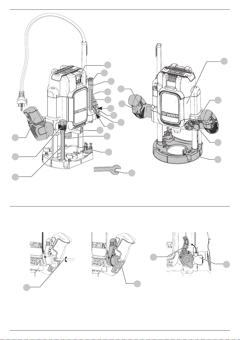
Fig. A
15A Plunge Router
Fig. B
1
18
19
20
12
2
3
15
16
17
14
8
2
4
5
9
11
13
56
6
7
10
6
7
39
54
1
Page 4
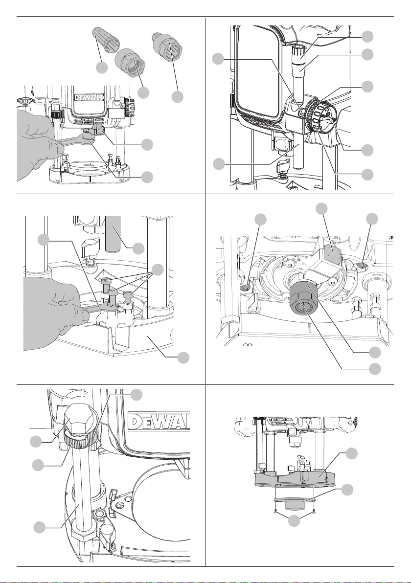
Fig.C
Fig.D
18
35
17
45
9
8
12
13
Fig.E Fig.F
55
12
11
19
14
15
16
8
57
57
Fig.G
2
10
9
36
4
Fig.H
51
10
23
24
5
25
Page 5
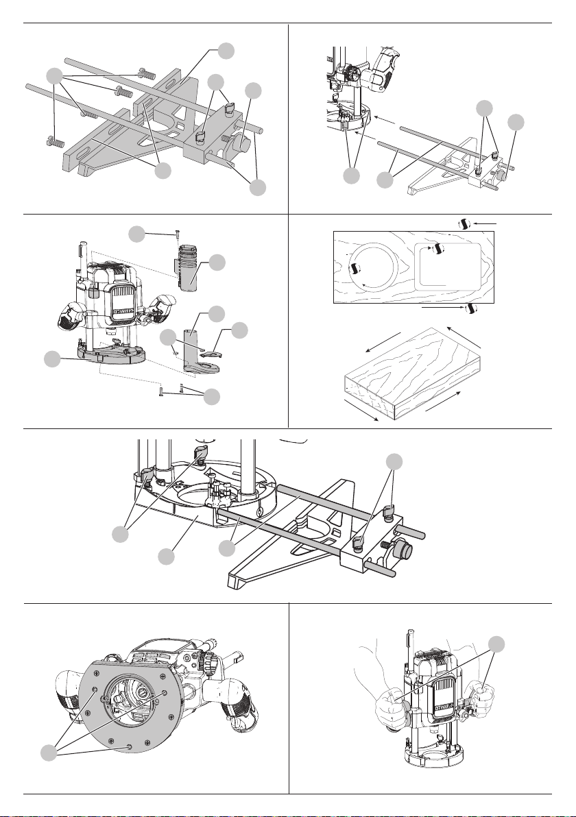
Fig.I
27
Fig.J
Fig.K
Fig.M
30
28
29
28
29
31
26
37
Fig.L
10
26
34
32
36
33
10
52
28
Fig.N
29
10
26
Fig.O
2
53
3
Page 6
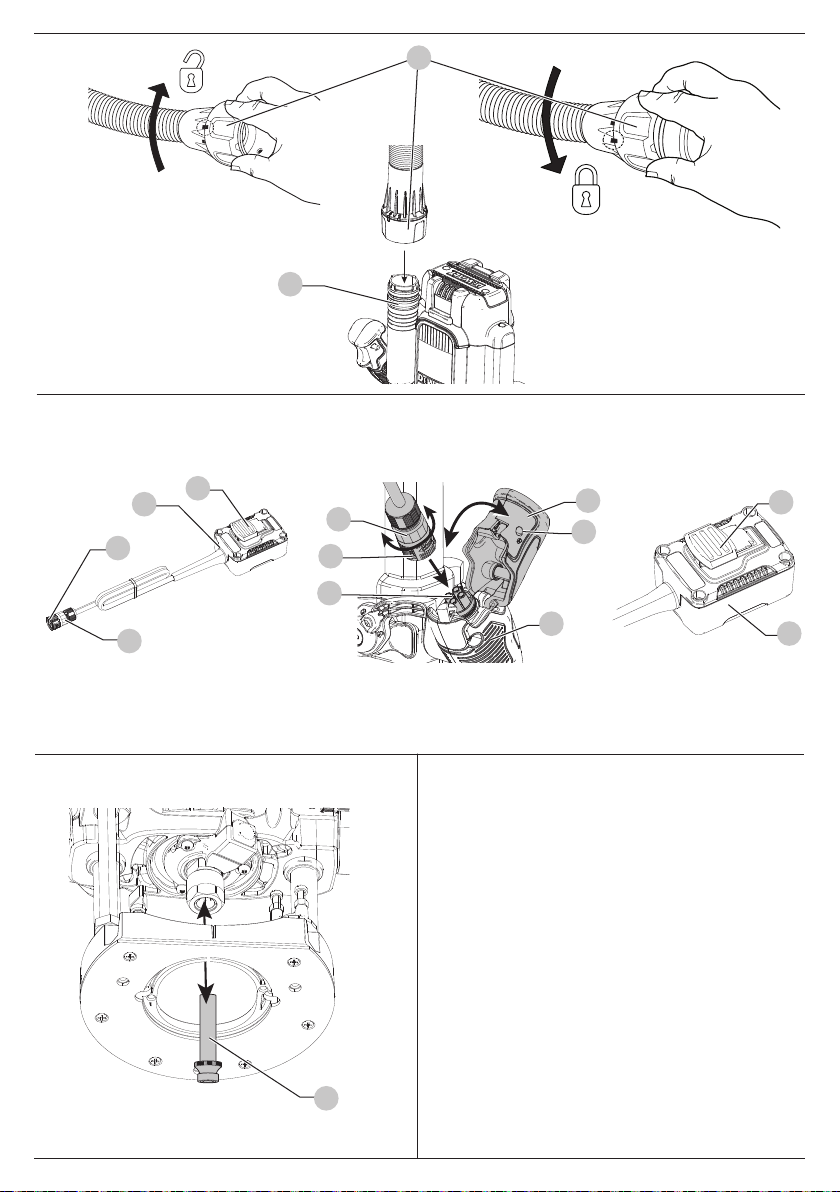
Fig.P
38
34
Fig.Q
Fig.R
(DWE627)
49
41
47
48
47
45
49
43
46
48
44
42
50
4
Page 7

PLUNGE ROUTER
DWE625, DWE627
ENGLISH
Congratulations!
You have chosen a DeWALT tool. Years of experience, thorough
product development and innovation make DeWALT one of the
most reliable partners for professional power toolusers.
Technical Data
DWE625 DWE625 DWE627
Voltage VAC115 230 230
Type 1 1 1
Power input W 2100 2300 2300
No‑load speed min-19000 ‑
Router carriage mm 2 column 2 column 2 column
Router carriage stroke mm 80 80 80
Max. cutting diameter mm 50 50 50
Collet size for Europe mm 12 12 12
Collet size for UK and ROI inch 1/2 1/2 1/2
Weight kg 6.1 6.1 6.2
Noise values and/or vibration values (triax vector sum) according to
EN62841‑2‑17:
LPA (emission sound pressure level) dB(A) 94.2 95.1 95.1
LWA (sound power level) dB(A) 105.2 106.1 106.1
K
(uncertainty for the given sound level)
Vibration emission value a
Uncertainty K = m/s20.31 0.31 0.31
dB(A) 2.5 2.5 2.5
= m/s24.1 3.1 3.1
h,hv
22000
9000 ‑
22000
9000 ‑
22000
EC-Declaration of Conformity
Machinery Directive
DWE625, DWE627
Plunge Router
DeWALT declares that these products described under Technical
Data are in compliance with:
2006/42/EC, EN62841‑1:2015 + AC:2015; EN62841‑2‑17:2017.
These products also comply with Directive 2014/30/EU and
2011/65/EU. For more information, please contact DeWALT at
the following address or refer to the back of themanual.
The undersigned is responsible for compilation of the technical
file and makes this declaration on behalf ofDeWALT.
Markus Rompel
Vice‑President Engineering, PTE‑Europe
DeWALT, Richard‑Klinger‑Straße 11,
65510, Idstein, Germany
08.09.2021
The vibration and/or noise emission level given in this information
sheet has been measured in accordance with a standardised test
given in EN62841 and may be used to compare one tool with
another. It may be used for a preliminary assessment ofexposure.
WARNING: The declared vibration and/or noise emission
level represents the main applications of the tool. However
if the tool is used for different applications, with different
accessories or poorly maintained, the vibration and/or
noise emission may differ. This may significantly increase
the exposure level over the total workingperiod.
An estimation of the level of exposure to vibration and/or
noise should also take into account the times when the tool
is switched off or when it is running but not actually doing
the job. This may significantly reduce the exposure level
over the total workingperiod.
Identify additional safety measures to protect the operator
from the effects of vibration and/or noise such as: maintain
the tool and the accessories, keep the hands warm (relevant
for vibration), organisation of workpatterns.
5
Page 8

ENGLISH
DECLARATION OF CONFORMITY
THE SUPPLY OF MACHINERY SAFETY
REGULATIONS 2008
PLUNGE ROUTER
DWE625, DWE627
DeWALT declares that these products described under “technical
data” are in compliance with:
The Supply of Machinery (Safety) Regulations, 2008, S.I. 2008/1597
(as amended), EN62841‑1:2015 + AC:2015; EN62841‑2‑17:2017.
These products conform to the following UK Regulations
Electromagnetic Compatibility Regulations, 2016, S.I.2016/1091
(asamended).
The Restriction of the Use of Certain Hazardous Substances
in Electrical and Electronic Equipment Regulations 2012, S.I.
2012/3032 (as amended).
For more information, please contact DeWALT at the following
address or refer to the back of the manual.
The undersigned is responsible for compilation of the technical
file and makes this declaration on behalf of DeWALT.
Karl Evans
Vice President Professional Power Tools EANZ GTS
DeWALT UK, 270Bath Road, Slough
Berkshire, SL1 4DX
England
08.09.2021
WARNING: To reduce the risk of injury, read the
instructionmanual.
a
Definitions: Safety Guidelines
The definitions below describe the level of severity for each
signal word. Please read the manual and pay attention to
thesesymbols.
DANGER: Indicates an imminently hazardous
situation which, if not avoided, will result in death or
seriousinjury.
WARNING: Indicates a potentially hazardous situation
which, if not avoided, could result in death or
seriousinjury.
CAUTION: Indicates a potentially hazardous situation
which, if not avoided, may result in minor or
moderateinjury.
NOTICE: Indicates a practice not related to
personal injury which, if not avoided, may result in
propertydamage.
Denotes risk of electricshock.
Denotes risk offire.
GENERAL POWER TOOL SAFETY WARNINGS
WARNING: Read all safety warnings, instructions,
illustrations and specifications provided with this
power tool. Failure to follow all instructions listed below
may result in electric shock, fire and/or seriousinjury.
SAVE ALL WARNINGS AND INSTRUCTIONS
FOR FUTUREREFERENCE
The term “power tool” in the warnings refers to your
mains‑operated (corded) power tool or battery‑operated (cordless)
powertool.
1) Work Area Safety
a ) Keep work area clean and well lit. Cluttered or dark
areas inviteaccidents.
b ) Do not operate power tools in explosive
atmospheres, such as in the presence of flammable
liquids, gases or dust. Power tools create sparks which
may ignite the dust orfumes.
c ) Keep children and bystanders away while operating
a power tool. Distractions can cause you to losecontrol.
2) Electrical Safety
a ) Power tool plugs must match the outlet. Never
modify the plug in any way. Do not use any adapter
plugs with earthed (grounded) power tools.
Unmodified plugs and matching outlets will reduce risk of
electricshock.
b ) Avoid body contact with earthed or grounded
surfaces, such as pipes, radiators, ranges and
refrigerators. There is an increased risk of electric shock if
your body is earthed orgrounded.
c ) Do not expose power tools to rain or wet conditions.
Water entering a power tool will increase the risk of
electricshock.
d ) Do not abuse the cord. Never use the cord for
carrying, pulling or unplugging the power tool. Keep
cord away from heat, oil, sharp edges or moving
parts. Damaged or entangled cords increase the risk of
electricshock.
e ) When operating a power tool outdoors, use an
extension cord suitable for outdoor use. Use of a cord
suitable for outdoor use reduces the risk of electricshock.
f ) If operating a power tool in a damp location is
unavoidable, use a residual current device (RCD)
protected supply. Use of an RCD reduces the risk of
electricshock.
3) Personal Safety
a ) Stay alert, watch what you are doing and use
common sense when operating a power tool. Do not
use a power tool while you are tired or under the
influence of drugs, alcohol or medication. A moment
of inattention while operating power tools may result in
serious personalinjury.
6
Page 9

b ) Use personal protective equipment. Always wear eye
protection. Protective equipment such as a dust mask,
non‑skid safety shoes, hard hat or hearing protection used
for appropriate conditions will reduce personalinjuries.
c ) Prevent unintentional starting. Ensure the switch
is in the off‑position before connecting to power
source and/or battery pack, picking up or carrying
the tool. Carrying power tools with your finger on the
switch or energising power tools that have the switch on
invitesaccidents.
d ) Remove any adjusting key or wrench before turning
the power tool on. A wrench or a key left attached
to a rotating part of the power tool may result in
personalinjury.
e ) Do not overreach. Keep proper footing and balance
at all times. This enables better control of the power tool
in unexpectedsituations.
f ) Dress properly. Do not wear loose clothing or
jewellery. Keep your hair and clothing away from
moving parts. Loose clothes, jewellery or long hair can be
caught in movingparts.
g ) If devices are provided for the connection of dust
extraction and collection facilities, ensure these are
connected and properly used. Use of dust collection can
reduce dust‑relatedhazards.
h ) Do not let familiarity gained from frequent use of
tools allow you to become complacent and ignore
tool safety principles. A careless action can cause severe
injury within a fraction of asecond.
4) Power Tool Use and Care
a ) Do not force the power tool. Use the correct power
tool for your application. The correct power tool
will do the job better and safer at the rate for which it
wasdesigned.
b ) Do not use the power tool if the switch does not turn
it on and off. Any power tool that cannot be controlled
with the switch is dangerous and must berepaired.
c ) Disconnect the plug from the power source and/
or remove the battery pack, if detachable, from
the power tool before making any adjustments,
changing accessories, or storing power tools. Such
preventive safety measures reduce the risk of starting the
power toolaccidentally.
d ) Store idle power tools out of the reach of children
and do not allow persons unfamiliar with the power
tool or these instructions to operate the power tool.
Power tools are dangerous in the hands of untrainedusers.
e ) Maintain power tools and accessories. Check for
misalignment or binding of moving parts, breakage
of parts and any other condition that may affect the
power tool’s operation. If damaged, have the power
tool repaired before use. Many accidents are caused by
poorly maintained powertools.
f ) Keep cutting tools sharp and clean. Properly
maintained cutting tools with sharp cutting edges are less
likely to bind and are easier tocontrol.
ENGLISH
g ) Use the power tool, accessories and tool bits etc.
in accordance with these instructions, taking into
account the working conditions and the work to be
performed. Use of the power tool for operations different
from those intended could result in a hazardoussituation.
h ) Keep handles and grasping surfaces dry, clean and
free from oil and grease. Slippery handles and grasping
surfaces do not allow for safe handling and control of the
tool in unexpectedsituations.
5) Service
a ) Have your power tool serviced by a qualified repair
person using only identical replacement parts. This
will ensure that the safety of the power tool ismaintained.
Safety Instructions for Routers
a ) Hold the power tool by insulated gripping sur faces
only, because the cutter may contact its own cord.
Cutting a “live” wire may make exposed metal parts
of the power tool “live” and could give the operator an
electricalshock.
b ) Use clamps or another practical way to secure and
support the workpiece to a stable platform. Holding
the work by your hand or against the body leaves it
unstable and may lead to loss ofcontrol.
c ) Keep handles dry, clean and free from oil and grease.
This will enable better control of thetool.
d ) Maintain a firm grip with both hands on the tool to
resist starting torque. Maintain a firm grip on the tool at
all times whileoperating.
e ) Keep hands away from cutting area above and
below the base. Never reach under the workpiece for
any reason. Keep the router base firmly in contact with
the workpiece whencutting.
f ) Never touch the bit immediately after use. It may be
extremelyhot.
g ) Be sure that the motor has stopped completely
before you lay the router down. If the bit is still
spinning when the tool is laid down, it could cause injury
ordamage.
h ) Be sure that the router bit is clear of the workpiece
before starting the motor. If the bit is in contact with
the workpiece when the motor starts, it could make the
router jump, causing damage orinjury.
i ) The permitted speed of the cutting bit must be at
least equal to the maximum speed marked on the
power tool. If cutting bits run faster than their rated
speed, they may break and flyoff.
j ) Always follow the bit manufacturer’s speed
recommendations as some bit designs require
specific speeds for safety or performance. If you are
unsure of the proper speed or are experiencing any type of
problem, contact the bitmanufacturer.
k ) Do not use router bits with a diameter in excess of
50mm(2") in thistool.
7
Page 10

ENGLISH
Residual Risks
WARNING: We recommend the use of a residual current
device with a residual current rating of 30mA orless.
In spite of the application of the relevant safety regulations
and the implementation of safety devices, certain residual risks
cannot be avoided. These are:
• Impairment ofhearing.
• Risk of personal injury due to flyingparticles.
• Risk of burns due to accessories becoming hot
duringoperation.
• Risk of personal injury due to prolongeduse.
SAVE THESE INSTRUCTIONS
Electrical Safety
The electric motor has been designed for one voltage only.
Always check that the power supply corresponds to the voltage
on the ratingplate.
Your DeWALT tool is double insulated in accordance
with EN62841; therefore no earth wire isrequired.
The DWE625 LX (115V) is intended to be used with a safety
transformer manufactured to BSEN61558 and BS4343. Never
work without this transformer inplace.
If the supply cord is damaged, it must be replaced only by
DeWALT or an authorised serviceorganisation.
Mains Plug Replacement
(U.K.& Ireland Only)
If a new mains plug needs to be fitted:
• Safely dispose of the oldplug.
• Connect the brown lead t o the live terminal in theplug.
• Connect the blue lead to the neutralterminal.
WARNING: No connection is to be made to the
earthterminal.
Follow the fitting instructions supplied with good quality plugs.
Recommended fuse for 230V U.K. plug: 13A.
Fitting a Mains Plug to 115V Units
(U.K.and Ireland Only)
• The plug fitted should comply with BS EN 60309(BS4343),
32Amps.
WARNING: Always ensure that the cable clamp is
correctly and securely fitted to the sheath of thecable.
Using an Extension Cable
If an extension cable is required, use an approved 3–core
extension cable suitable for the power input of this tool (see
Technical Data).The minimum conductor size is 1.5 mm2; the
maximum length is 30m.
When using a cable reel, always unwind the cablecompletely.
Package Contents
The package contains:
1 Router
1 Collet 12mm (1/2" UK & ROI)
1 Parallel fence
2 Guide rods
1 Guide bush (30mm)
1 22mm wrench
1 SA Dust extraction tube
1 Remote Switch Box (DWE627 only)
1 Instruction manual
1 Fine adjustment
• Check for damage to the tool, parts or accessories which may
have occurred duringtransport.
• Take the time to thoroughly read and understand this manual
prior tooperation.
Markings on Tool
The following pictograms are shown on the tool:
Read instruction manual beforeuse.
a
Wear earprotection.
g
Wear eyeprotection.
f
Visible radiation. Do not stare intolight.
n
Date Code Position (Fig.A)
The date code
is printed into thehousing.
Example:
Description (Fig.A)
1
Speed control wheel
2
Main handles
3
On/off trigger switch
4
Thumb wheel
5
Height stop rod
6
Plunge lock lever
7
Quick release button
8
Spindle lock button
9
Collet assembly
10
Base plate
56
, which also includes the year of manufacture,
2021XX XX
Year and Week of Manufacture
WARNING: Never modify the power tool or any part of it.
Damage or personal injury couldresult.
8
Page 11

11
Multiple position turret stop
12
Depth stop bar
13
22mm wrench
14
Quick zero reset ring
15
Quick height adjuster lock
16
Quick height adjuster
17
Pointer
18
Fine adjuster
19
Fine zero reset ring
20
Lock on button switch
Intended Use
The DWE625 and DWE627 routers have been designed for
professional heavy duty routing of wood, wood based materials
andplastics.
These routers are intended for routing grooves, edges, profiles
and slots as well as copyrouting.
DO NOT use under wet conditions or in the presence of
flammable liquids orgases.
The DWE625 and DWE627 are professional powertoolsl.
The DWE627 is designed so that it can be installed into a router
table. The router may only be installed in tables that meet the
legal safety requirements for routertables.
DO NOT let children come into contact with the tool.
Supervision is required when inexperienced operators use
thistool.
• Young children and the infirm. This appliance is not
intended for use by young children or infirm persons
withoutsupervision.
• This product is not intended for use by persons (including
children) suffering from diminished physical, sensory or
mental abilities; lack of experience, knowledge or skills
unless they are supervised by a person responsible for their
safety. Children should never be left alone with thisproduct.
CAUTION: Before operating any of the controls, read the
followingsections.
Plunge Lock Lever (Fig.B)
The plunge lock lever
specifiedheight.
1. Press down the plunge lock lever
audible "Click" when you want to lower the router bit into
theworkpiece.
2. You can lower the unit until it reaches your presetstop.
3. To lock the tool in place along its vertical travel, press quick
release button
6
allows you to stop the working bit at a
6
until you hear an
7
.
Collets (Fig.C)
WARNING:
that match the installed collet. Smaller shank bits will
not be secure and could become loose duringoperation.
Projectile hazard. Only use bits with shanks
ENGLISH
CAUTION: Never tighten the collet without first installing
a router bit in it. Tightening an empty collet, even by hand,
can damage thecollet.
A collet is included with thisrouter.
‑ 12mm : Europe
‑ 1/2” : Great Britain
1. To change collets
2. Sharply pull the old collet out of the collet nut
insert the new collet
3. Push firmly so that the new collet snaps past the retainer
spring in the colletnut.
35
, unscrew the collet assembly
35
.
36
9
and
.
Multiple Position Turret Stop (Fig.E)
WARNING: Do not change the turret stop while the
router is running. This will place your hands too near the
cutterhead.
The turret stop
can be plunged. It consists of three screws of different lengths
that serve to define the depth of cut by limiting the travel of
the depth stop bar
1. Routing depth can be set by selecting the screw of the
appropriate length on theturret.
2. The turret is rotatable with detent stops to properly align
thescrews.
3. It is the interaction of the depth stop bar and the turret stop
that determine the routingdepth.
4. If none of the provided screws seems close to the desired
height each can be adjusted by loosening the hex nut at the
bottom and then turning the screw either in or out to make it
the proper length. After adjusting this screw be sure to tighten
the hex nut at thebottom with the an 8mm wrench
5. Refer to section Setting the Routing Depth for instructions
on how to use the turret stop in an actualoperation.
11
limits the downward distance that the tool
12
.
55
.
Height Stop Rod and Height Stop Thumb
Wheel (Fig.G)
The height stop rod
the unit can travel up the rails. The system is adjustable from
full down where the unit cannot rise regardless of the position
of the plunge release lever to full up where the bottom of the
collet is 80mm (3‑5/32") above theworkpiece.
For convenience, the thumb wheel is equipped with a quick
release button
fast positioning by simply depressing the button in the side of
thewheel.
NOTE: It is easier to move the height stop thumb wheel UP
if the plunge release lever is locked and easier to move the
thumb wheel down if the unit is first moved down by releasing
the plunge release lever and then tightening it.
5
and thumb wheel
23
that allows you to disengage the threads for
4
limit how high
ASSEMBLY AND ADJUSTMENTS
WARNING: To reduce the risk of serious personal
injury, turn tool off and disconnect tool from power
source before making any adjustments or removing/
installing attachments or accessories. An accidental
start‑up can causeinjury.
9
Page 12

ENGLISH
Installing and Removing a Cutter (Fig.C, F)
WARNING: Do not tighten the collet without a
cutterfitted.
WARNING: Always use cutters with shanks which match
the diameter of thecollet.
WARNING: Do not use cutters larger than 50mm (2")
unless the router is fitted in a routertable.
CAUTION: Care should be taken when removing cutter to
avoid cuts tofingers.
Installing a Cutter
1. Insert at least three fourths of the shank length of the cutter
into thecollet assembly
2. Press the spindle lock
islocked.
NOTE: You may need to turn the spindle slightly to
engageit.
3. Turn the collet nut
22mm wrench
9
.
8
forward until the router spindle
36
counterclockwise with the supplied
13
to tightenit.
Removing a Cutter
1. Press the spindle lock button
spindle islock.
2. Turn the collet nut
3. Keep turning the wrench until the collet nut tightens and
4. The cutter should now slideout.
13
wrench
then loosens again. This is the fail‑safe mechanism releasing
thecollet.
NOTE: Each time you finish using a cutter, remove it and
store it in a safeplace.
toloosen.
8
forward until the router
9
clockwise with the supplied 22mm
Fine Height Adjuster (Fig.A, D, E)
CAUTION: Ensure that the plunge locking lever is
unlocked. Never use unnecessary force to rotate the fine
height adjustermechanism.
CAUTION: Do not remove the screw on hexnuts.
The fine height adjuster can be used in portable mode or when
the router is held inside atable.
Adjusting the Depth of Cut (Fig.A, D, E)
Your router is equipped with a high‑precision depth adjustment
system including a zero reset ring for both the quick height
adjuster and the fine heightadjuster.
Quick Adjustment Using the Graduation with Zero Reset Ring
1. Loosen the depth stop quick height adjuster knob
2. Unlock the plunge limiter by pushing the release
6
lever
down.
3. Lower the router carriage until the cutter is in contact with
theworkpiece.
4. Press the quick locking button
5. Set the quick height adjuster
adjust reset ring
in contact with the turret stop
10
19
to zero. The depth stop bar
7
.
16
to zero and reset the fine
11
.
15
12
.
must be
6. Adjust the depth of cut using the quick height adjuster
and the corresponding graduation. The adjusted depth of
cut is indicated by the pointer
7. Tighten the quick height adjuster lock
Fine Adjustment
When not using a depth template, or if the depth of cut
needs readjustment, it is recommended to use the fine height
18
adjuster
1. Adjust the depth of cut as described in Adjusting the Depth
2. Set the fine height adjuster to zero using the fine zero reset
3. Rotate the fine height adjuster
.
ofCut.
19
ring
position: one turn corresponds to approximately 1mm and
1mark to 0.1mm.
17
.
15
18
to the required
.
16
Fitting a Guide Bush (Fig.H)
Together with a template, guide bushes play a valuable part in
cutting and shaping to apattern.
• Fit the guide bush
screws
25
asshown.
24
to the router base
10
using the
Fitting the Parallel Fence (Fig.I, J)
1. Fit the guide rod
2. Slide the parallel fence
3. Tighten the wing bolts
26
to the router base
27
over therods.
28
temporarily.
Adjusting the Parallel Fence (Fig.A,I, J)
1. Draw a cutting line on thematerial.
2. Lower the router carriage until the cutter is in contact with
theworkpiece.
3. Push quick release button
using the thumb wheel
4. Position the router on the cuttingline.
5. Slide the parallel fence
tighten the wing bolts
6. Adjust the parallel fence using the fine adjustment knob
The outer cutting edge of the cutter must coincide with the
cuttingline.
7. If required, loosen the screws
to obtain the desired guidinglength.
Dust Extraction (Fig. A, K, P)
Dust from materials such as lead‑containing coatings and some
wood types, can be harmful to one’s health. Breathing‑in the
dust can cause allergic reactions and/or lead to respiratory
infections of the user orbystanders.
Certain dust, such as oak or beech dust, is considered
carcinogenic, especially in connection with
wood‑treatmentadditives.
Observe the relevant regulations in your country for the
materials to beworked.
The vacuum cleaner must be suitable for the material
beingworked.
When vacuuming dry dust that is especially detrimental to
health or carcinogenic, use dust class M vacuumcleaner.
7
and limit the carriage return
4
.
27
against the workpiece and
28
.
10
.
30
and adjust the strips
29
31
.
Page 13

Connecting Dust Extraction Adaptor (Fig.K)
53
.
32
until it clicks
34
32
, a
to
The dust extraction adaptor consists of a main section
33
cover
, an extraction tube adaptor
37
screw
, two base screws
1. Slide the cover
intoplace.
2. Place the main section
screws
3. Remove screw
screw to assemble the extraction tube adaptor
therouter.
Connecting Dust Extractor Hose (Fig.P)
WARNING: Risk of dust inhalation.To reduce the risk of
personal injury, ALWAY S wear an approved dustmask.
A dust extraction tube adaptor
Vacuum hoses on most vacuum extractors will fit directly into
the dust extractionspout.
WARNING: ALWAYS use a vacuum extractor designed
in compliance with the applicable directives regarding
dust emission when sawing wood.Vacuum hoses of most
common vacuum cleaners will fit directly into the dust
extractionoutlet.
1. Connect a dust extractor hose
adaptor
NOTE: When using dust extraction, be sure that the dust extractor
is out of the way and secure so that it will not tip over or interfere
with the router or workpiece. The dust extractor hose and power
cord must also be positioned so that they do not interfere with
the router or workpiece. If the dust extractor or dust extractor
hose cannot be positioned properly, it should beremoved.
33
onto the main section
52
and nuts
34
using the DeWALT AirLocksystem.
32
53
37
from the top of the router and use this
34
52
on the base and secure with two
.
, one extraction tube
and two nuts
34
is supplied with yourtool.
38
to the extraction tube
OPERATION
Instructions for Use
WARNING: Always observe the safety instructions and
applicableregulations.
WARNING: To reduce the risk of serious personal
injury, turn tool off and disconnect tool from power
source before making any adjustments or removing/
installing attachments or accessories. An accidental
start‑up can causeinjury.
Proper Hand Position (Fig.O)
WARNING: To reduce the risk of serious personal injury,
ALWAY S use proper hand position asshown.
WARNING: To reduce the risk of serious personal
injury, ALWAY S hold securely in anticipation of a
suddenreaction.
Proper hand position requires both hands on the main
2
handles
.
Using the Router(Fig.A, L)
CAUTION: Turn the router on before plunging the cutter
ENGLISH
head into theworkpiece.
CAUTION:
• Excessive cutting may cause overload of the motor
or difficulty in controlling the tool, the depth of
cut should not be more than 15mm (19/32") at a
pass when cutting grooves with a 8mm (5/16")
diameterbit.
• When cutting grooves with a 20mm (25/32")
diamter bit, the depth of cut should not be more
than5mm(3/16") at apass.
• For extra deep grooving, make two or three passes
with progressively deeper bitsettings.
CAUTION:
• After long periods of working at low speeds, allow the
machine to cool down by running it for three minutes
at maximum speed, with noload.
All common routing tasks can be performed with the plunge
cut router on all types of wood and plastic:
‑ Grooving
‑ Rabbeting
‑ Recessing
‑ Veining
‑ Profiling
To prevent overload of the tool by using the wrong speed
selection, follow the reccommended settings below:
CUTTER DIAMETER
10 ‑ 30 mm 30 ‑ 50 mm
MATERIAL
Hardwood 7 ‑ 5 6 ‑ 2
Softwood 7 ‑ 6 7 ‑ 5
Chipboard Faced 7 ‑ 6 7 ‑ 4
Plastic 7 ‑ 5 7 ‑ 4
NOTE: Only carbide‑tipped cutters should be used on panels
faced with plastic laminates. The hard laminates will quickly dull
steelcutters.
NOTE: For better plunge sliding movement, frequently clean
the columns of dust ordebris. If the plunging movement is not
moving as smooth as desired, lubricate the columns with a dry
teflonlubricant.
1. After setting the cutting depth as described, locate the
router such that the bit is directly over the place you will
becutting.
2. With the router running, lower the unit smoothly down into
the workpiece. DO NOT JAM THE ROUTERDOWN.
3. When the tool reaches the pre‑set depth, push the quick
release button
4. When you have finished routing, push the plunge lock
lever
out of theworkpiece.
5. Always feed the router opposite to the direction in which
the cutter isrotating. Refer to Fig.L.
7
tolock.
6
to unlock and let the spring lift the router directly
SPEED SELECTION
11
Page 14

ENGLISH
On/Off Trigger Switch (Fig.A)
WARNING: To reduce the risk of serious personal
injury, turn unit off and disconnect it from power
source before making any adjustments or removing/
installing attachments or accessories. An accidental
start‑up can causeinjury.
1. To turn the unit on, squeeze the on/off trigger switch
Continue to squeeze the trigger switch or press the lock on
button switch
2. To turn the unit off:
a. If lock on trigger is engage, release the lock on button by
squeezing and releasingtrigger.
b. If the lock on switch is not engage, fully release thetrigger.
20
for continuousrunning.
3
.
Variable Speed Dial (Fig.A)
WARNING: If the speed control ceases to operate, or is
intermittent, stop using the tool immediately. Take it to a
DeWALT factory or authorized service facility forrepair.
NOTICE: The router is equipped with electronics to
monitor and maintain the speed of the tool while cutting.
In low and medium speed operation, the speed control
prevents the motor speed from decreasing. If you expect
to hear a speed change and continue to load the motor,
you could damage the motor by overheating. Reduce
the depth of cut and/or slow the feed rate to prevent
tooldamage.
Refer to the Speed Selection Chart to choose a router speed.
Turn the speed dial
variable from 9000to 22000rpm using the speed dial
1. Turn the speed dial to the required position. The dial is
numbered from 1–7and corresponds to router speeds of
9000rpm to 22000rpm.
2. Use the slower settings for large diameter cutters and the
faster settings for small diameter cutters.
3. The correct setting will also depend on the density of the
material, depth of cut and feed speed of therouter.
NOTE: A noticeable loss of motor rpm means
motoroverload.
DIAL SETTING APPROXIMATE RPM
The speeds in this chart are approximate and are for reference
only. Your router may not produce the exact speed listed for the
dialsetting.
1
to control routerspeed. The speed is
SPEED SELECTION CHART
1 9000
2 11000
3 13000
4 15000
5 18000
6 20000
7 22000
1
.
WARNING: Always follow the bit manufacturer’s speed
recommendations as some bit designs require specific
speeds for safety orperformance.
If you are unsure of the proper speed or are experiencing any
type of problem, contact the bitmanufacturer.
n
LED Worklight (Fig.F)
CAUTION: Do not stare into worklight. Serious eye
injury couldresult.
Two LED worklights
1. The worklights
router is connected to the mains powersupply.
2. To switch off the worklights the router must be
disconnected from mains powersupply.
NOTE: The worklight is for lighting the immediate work surface
and is not intended to be used as aflashlight.
Setting Plunge Lock System (Fig.B)
The plunge is fully automatically locking for all cuts. For heavy
cut operations, ensure to push the lever towards the toolbody.
The plunge lock lever
lever does not touch the motor body, if the plunge lock lever
begins to hit the body when the quick release lever is pushed,
readjust the locking lever position as follows:
1. Push in quick release button
unlockautomatically.
2. Using a Torx 20star bit
on the plunge lock lever
Do not fullyremove.
3. Lift the plunge lock lever, rotate and reposition the plunge
lock lever at position2(at eleven o'clock).
4. Tighten the shoulderscrew.
5. If after setting to position 2sliding is not correct, repeat
steps 1to 3and reposition the lock lever at position 1.
Tighten the shoulderscrew.
Moulding Natural Timbers
WARNING: When routing always lock the plunge
lockinglever.
When edge moulding natural timbers, always mould the end
grain first, followed by the long grain.This ensures that if there is
breakout, it will be removed when the long grain isrouted.
Setting the Routing Depth (Fig.D, E)
1. Place the router with cutter fitted on to theworkpiece.
2. Set the multiple position turret stop
3. Loosen the knob quick adjustment
depthstop
4. Push down the plunging lock lever
5. Lower the router slowly until the cutter touches
the workpiece and secure it in place by pushing
quickreleasebutton
57
are located next to the collet assembly
57
will constantly illuminate when the
6
position is set at the factory so the
7
. The plunge lever lock will
39
, loosen the shoulder screw
6
with six counterclockwise turns.
11
15
12
.
7
.
securing the
6
to startplunging.
54
asrequired.
9
.
12
Page 15

6. Rotate the quick height adjuster
12
bar
touches multiple turret stop
by tightening the quick height adjuster lock
7. If the depth of cut needs re‑adjustment, it is recommended
to use quick depth adjuster
height adjuster for accuratesettings.
8. Adjust the depth of cut using the fine height adjuster
NOTE: One turn of the fine height adjuster
to 1mm (3/64"), one turn of the quick height adjuster
corresponds to 40mm (1‑1/2")
9. Read the depth of cut using the quick zero reset ring
and fine zero reset ring
10. The distance between the top of the revolving depth stop and
the bottom of the depth stop is the required depth ofcut.
11. The rotating turret stop screws
to three depths of cut. The height can be adjusted using a flat
screwdriver and a 8mm (5/16")wrench.
NOTE: By rotating the turret stop, three depth settings can
be quicklymade.
16
until the depth stop
13
. Secure in position
16
for gross settings, or the fine
19
.
11
can be used for setting up
15
.
18
corresponds
18
14
15
Fine Height Adjuster (Fig. D)
This router has a built in fine height adjuster. This should be
used when fine height adjustment of the cutter is required.
This is especially recommended when using dovetail jigs or
routertables.
Direction Of Feed (Fig.L)
WARNING:
opposite than shown in Fig.L). Climb‑cutting increases the
chance for loss of control resulting in possible injury. When
climb‑cutting is required (backing around a corner), exercise
extreme caution to maintain control of router. Make smaller
cuts and remove minimal material with eachpass.
The direction of feed is very important when routing and can
make the difference between a successful job and a ruined
project. Fig. L show proper direction of feed for mostcuts.
1. When routing along an edge, the direction of the router
travel should be against that of the rotation of the cutter.
This will create the correct cutting action and prevent the
cutter from snatching. It will also pull the router towards the
workpiece and the side fence or guide bearing will be less
likely to wander from the edge of theworkpiece.
Feed Speed
The speed at which the cutter is fed into the wood must not be
too fast that the motor slows down, or too slow that the cutter
leaves burn marks on the face of thewood.
NOTE: Practice judging the speed by listening to the sound of
the motor whenrouting.
Sequence of Plunging
WARNING: When routing always lock the plunge
lockinglever.
1. Plunge down and lock the motor carriage, by pushing quick
release button
2. Perform the desired routingoperation.
3. Push down the plunge lock lever
returns to the normalposition.
Avoid climb‑cutting (cutting in direction
7
.
6
and the motor carriage
ENGLISH
Using a Side Fence (Fig. M)
CAUTION: Ensure working position is comfortable and at
a suitable workingheight.
1. Ensure the wing bolts
guide rods
wingbolts.
2. Adjust the fence fine adjustment knob
distance and clamp in place with the wing bolts
3. Then lower the cutter height until the cutter is just above
theworkpiece.
4. Fine adjustments are possible by loosening the
wing bolt
adjustmentknob
5. Tighten the wing bolt
NOTE: One revolution of the side fence fine adjustment
knob
6. Lower the cutter onto the workpiece and set the cutter
height by to the requireddistance. Refer to Setting the
RouterDepth.
7. Switch the router on and after the cutter reaches full
speed, gently lower the cutter into the workpiece and lock
theplunge.
8. Feed along the workpiece, keeping sideways pressure to
ensure the side fence does not wander away from the
workpiece edge and downward pressure on the inside hand
to prevent the router fromtipping.
9. When finished, raise the router, secure with the plunge
locking lever
NOTE: When starting the cut, keep the pressure on the front
cheek until the back cheek contacts the workpieceedge.
NOTE: At the end of the cut, keep pressure on the back
cheek until the cut is finished. This will prevent the router
cutter swinging in at the end of the workpiece and nipping
thecorner.
26
28
29
equals 3/64" (1.0mm) of sidefeed.
28
into the routing base
and adjusting the side fence fine
6
and switch the routeroff.
are fully released. Slide the
29
.
28
to secure theposition.
10
and tighten the
29
to the required
28
.
Side Fence Routing (Fig.I, J)
The side fence is used to guide the router when moulding,
edge profiling or rebating the edge of a workpiece or when
routing grooves and slots in the center of the workpiece,
parallel to theedge.
The edge of the workpiece must be straight andtrue.
31
The strips
1/8" (3mm) gap each side of thecutter.
are adjustable and should be set ideally with a
Guiding Off a Batten
Where an edge guide cannot be used, it is also possible to guide
the router along a batten clamped across the workpiece (with
an overhang at both ends.)
Freehand Routing
WARNING: Make shallow cuts only!
Use cutters with a max. diameter of 12mm.
Your router can also be used without any sort of guide, e.g. for
signwriting or creativework.
13
Page 16

ENGLISH
Table Mode (Fig. Q)
(DWE627 ONLY)
WARNING: Before DWE627 is installed into the
router table, check that the router table meets all
of the legal safety requirements for router tables.
Read all safety warnings, instructions, and specifications
provided with the router table. Failure to follow all
instructions and safety rules may result in electric shock,
fire and/or seriousinjury.
WARNING: To reduce the risk of serious personal
injury, turn unit off and disconnect it from power
source before making any adjustments or removing/
installing attachments or accessories. An accidental
start‑up can causeinjury.
WARNING: Do not use the DWE627 as a handheld
router if the power switch box isconnected.
CAUTION: If there is dust inside the power switch
socket, clean it out before using the power switchbox.
1. To connect the power switch box
disconnect the tool from its powersource.
2. Attach the power switch box
position easily accessible by hand and where unintentional
switching on isprevented.
NOTE: The external switch can be secured to the router
table with the four mountingholes.
3. The cable must be installed and fastened in such a way that
it cannot be squeezed or touch sharpedges.
4. Push in on the lock button
44
handle
handle cap
NOTE: If there is dust inside the power switch socket, clean
it out before using the power switchbox.
5. Keep pushing the lock button
cap
6. Ensure the paddle switch of the power switch box is in the
off position before connecting to the power switchsocket.
7. Connect power switch box plug
socket
8. Thread the ring nut
the power switch socket
9. Attach the plunge router under the workbench, as required
per your application or the instruction for the routertable.
10. Plug the tool back into its power source. The router can now
switched on and off by acting on paddle
switch box
11. Pull out the paddle
paddle to switch itoff.
with a pen or a small screwdriver to unlock the
45
.
45
to access the power switch socket
46
.
48
of power switch box plug
42
.
49
to start the tool and push in the
42
to the router,
42
to the workbench in a
43
located on the left side
43
in and rotate the handle
46
47
to the power switch
46
to lock it securely in place.
49
on the power
.
47
to
Depth Adjustment with the Router Installed
in Inverted Position (Fig.G)
WARNING: For installing the router in inverted
position, refer to the relevant instruction manual on the
stationarytool.
1. Remove the cap nut
replace it with the height adjusting tool (DE6966) available
as anoption.
2. Screw the threaded end of the height adjusting tool to the
height stop rod
3. Set the depth of cut using the adjuster on the height
adjustingtool.
51
and the thumb wheel
5
.
4
and
Routing with Pilot Cutters (Fig. R)
Where a parallel guide or guide bush are inappropriate, it is
possible to use pilot cutters
These include collets (12 – 12.7 mm), a height adjusting tool
and router table for use in inverted position, finger jointing tools
for dovetail and finger jointing jigs, dovetail jointing templates,
adjustable guide bush holder and guide bushes and guide rails
in variouslengths.
50
for cutting shapededges.
MAINTENANCE
Your power tool has been designed to operate over a long
period of time with a minimum of maintenance. Continuous
satisfactory operation depends upon proper tool care and
regularcleaning.
WARNING: To reduce the risk of serious personal
injury, turn tool off and disconnect tool from power
source before making any adjustments or removing/
installing attachments or accessories. An accidental
start‑up can causeinjury.
Repairs
WARNING: To assure product SAFETY and RELIABILITY,
repairs, maintenance and adjustment (including power
cord repairs, and brush inspection and replacement, when
applicable) should be performed by a DeWALT factory
service center or a DeWALT authorized service center.
Always use identical replacementparts.
C
Lubrication
Your power tool requires no additionallubrication.
D
Cleaning
WARNING: Blow dirt and dust out of the main housing
with dry air as often as dirt is seen collecting in and around
the air vents. Wear approved eye protection and approved
dust mask when performing thisprocedure.
WARNING: Never use solvents or other harsh chemicals
for cleaning the non‑metallic parts of the tool. These
chemicals may weaken the materials used in these parts.
Use a cloth dampened only with water and mild soap.
Never let any liquid get inside the tool; never immerse any
part of the tool into aliquid.
14
Page 17

Optional Accessories
WARNING: Since accessories, other than those offered
by DeWALT, have not been tested with this product, use
of such accessories with this tool could be hazardous.
To reduce the risk of injury, only DeWALT recommended
accessories should be used with thisproduct.
Consult your dealer for further information on the
appropriateaccessories.
Base Mounting Points for Accessories (Fig.N)
This router has three threaded holes
allows it to attach to otheraccessories.
53
built into the base that
Protecting the Environment
Separate collection. Products marked with this symbol
must not be disposed of with normal householdwaste.
Products contain materials that can be recovered
or recycled reducing the demand for raw materials.
w
Please recycle electrical products according to local provisions.
Further information is available at www.2helpU.com.
ENGLISH
15
Page 18

16
Page 19

17
Page 20

Belgique et
Luxembourg België en Luxemburg
Danmark DeWALT (Stanley Black&Decker AS)
Deutschland DeWALT
Ελλά DeWALT (Ελλάς) Α.Ε.
España DeWALT Ibérica, S.C.A.
France DeWALT (Stanley Black & Decker France SAS)
Schweiz
Suisse
Svizzera
Ireland DeWALT
Italia DeWALT
Nederlands DeWALT
Norge DeWALT
Österreich DeWALT
Portugal DeWALT
Suomi DeWALT
Sverige DeWALT
Türkiye
United Kingdom DeWALT, 270 Bath Road;
Australia DeWALT
Middle East Africa DeWALT
DeWALT ‑ Belgium BVBA
Egide Walschaertsstraat 16
2800 Mechelen
Roskildevej 22
2620 Albertslund
Richard Klinger Str. 11
65510 Idstein
EΔΡΑ‑ΓΡΑΦΕΙΑ : Στράβωνος 7
& Λ. Βουλιαγμένης, Γλυφάδα 166 74, Αθήνα
SERVICE : Ημερος Τόπος 2 (Χάνι Αδάμ) – 193 00 Ασπρόπυργος
Parc de Negocios “Mas Blau”
Edificio Muntadas, c/Bergadá, 1, Of. A6
08820 El Prat de Llobregat (Barcelona)
62 Chemin de la Bruyère
CS 60105,
69574 DARDILLY Cedex
DeWALT
In der Luberzen 42
8902 Urdorf
Building 4500, Kinsale Road
Cork Airport Business Park
Cork, Ireland
via Energypark 6
20871 Vimercate (MB), IT
Netherlands BVPostbus 83,
6120 AB BORN
Postboks 4613
0405 Oslo, Norge
Werkzeug Vertriebsges m.b.H
Oberlaaerstrasse 248, A‑1230 Wien
Ed. D Dinis, Quina da Fonte
Rua dos Malhoes 2 2A 2º Esq.
Oeiras e S. Juliao da Barra, paço de Arcos e Caxias
2770 071 Paço de Arcos
PL47
00521 Helsinki, Suomi
BOX 94
43122 Mölndal
Sverige
Sanayi ve Ticareet Bakanlığı tebliğince kullanim ömrü 7 yıldır.
Stanley Black & Decker Turkey Alet Üretim San. Tic. Ltd.Şti.
AND Kozyataği ‑ İçerenköy Mah. Umut Sok. AND Ofis Sit. No: 10‑12 / 82‑83‑84
Ataşehir/İstanbul, Türkiye
Slough, Berks SL1 4DX
810 Whitehorse Road Box Hill
VIC 3128 Australia
P.O. Box ‑ 17164,
Jebel Ali Free Zone (South), Dubai, UAE
Tel: NL 32 15 47 37 63
Tel: FR 32 15 47 37 64
Fax: 32 15 47 37 99
Tel: 70 20 15 10
Fax: 70 22 49 10
Tel: 06126‑21‑0
Fax: 06126‑21‑2770
Τηλ: 00302108981616
Φαξ: 00302108983570
Tel: 934 797 400
Fax: 934 797 419
Tel: 04 72 20 39 20
Fax: 04 72 20 39 00
Tel: 044 ‑ 755 60 70
Fax: 044 ‑ 730 70 67
Tel: 00353‑2781800
Fax: 01278 1811
Tel: 800‑014353
39 039‑9590200
Fax: 39 039‑9590311
Tel: 31 164 283 063
Fax: 31 164 283 200
Tel: 45 25 13 00
Fax: 45 25 08 00
Tel: 01 ‑ 66116 ‑ 0
Fax: 01 ‑ 66116 ‑ 614
Tel: +351 214667500
Fax: +351214667580
Puh: 010 400 4333
Faksi: 0800 411 340
Tel: 031 68 61 60
Fax: 031 68 60 08
Tel: +90 216 665 2900
Faks: +90 216 665 2901
Tel: 01753‑567055
Fax: 01753‑572112
Tel: Aust 1800 338 002
Tel: NZ 0800 339 258
Tel: 971 4 812 7400
Fax: 971 4 2822765
www.dewalt.be
[email protected]
www.dewalt.dk
[email protected]
www.dewalt.de
[email protected]
www.dewalt.gr
[email protected]
www.dewalt.es
[email protected]
www.dewalt.fr
[email protected]
www.dewalt.ch
[email protected]
www.dewalt.ie
[email protected]
www.dewalt.it
www.dewalt.nl
www.dewalt.no
[email protected]
www.dewalt.at
[email protected]
www.dewalt.pt
[email protected]
www.dewalt.fi
[email protected]
www.dewalt.se
[email protected]
www.dewalt.com.tr
[email protected]
www.dewalt.co.uk
[email protected]
www.dewalt.com.au
www.dewalt.co.nz
www.dewalt.ae
[email protected]
N896714
08/21
 Loading...