

Page 1

If you have questions or comments, contact us.
Pour toute question ou tout commentaire, nous contacter.
Si tiene dudas o comentarios, cont_ctenos.
iNSTRUCTiON MANUAL
GUIDE D'UTILISATION
INSTRUCTIVO DE OPERACION, CENTROS DE SERVICIO Y P©LIZA DE
GARANT[A. ADVERTENClA: LEASE ESTE INSTRUCTIVO ANTES DE
USAR EL PRODUCTO.
MANUAL DE INSTRUCCIONES
D28499, DWE4557, DWE4557G, DWE4559CN, DWE4559NG, DWE4559CNG, DWE4559N,
DWE4597, DWE4597N, DWE4599N
Heavy Duty Large Angle Grinders
Grandes rectifieuses coud_es de service intensif
Esmeriladoras de &ngulo grande para trabajo pesado
®
Page 2

Definitions: Safety Guidelines
The definitions below describe the level of severity for each
signal word. Please read the manual and pay attention to these
symbols.
,_DANGER: Indicates an imminently hazardous situation
which, if not avoided, will result in death or serious injury.
WARNING," Indicates a potentially hazardous situation which,
if not avoided, could result in death or serious injury.
CAUTION: Indicates a potentially hazardous situation which,
if not avoided, may result in minor or moderate injury.
NOTICE: Indicates a practice not related to personal injury
which, if not avoided, may result in property damage.
_11
IF YOU HAVE ANY QUESTIONS OR COMMENTS ABOUT THIS OR
ANY DEWALT TOOL, CALL US TOLL FREE AT: 1-800-4-D_=WALT
(1-800-433-9258}.
WARNING: To reduce the risk of injury, read the instruction
manual.
General Power Tool Safety Warnings
_ WARNING! Read all safety warnings and all instructions.
Failure to follow the wamings and instructions may result in
electric shock, fire and/or serious injury.
SAVE ALL WARNINGS AND INSTRUCTIONS
FOR FUTURE REFERENCE
The term "power tool" in the warnings refers to your mains-operated
(corded) power tool or battery-operated (cordless) power tool.
1} WORK AREA SAFETY
a) Keep work area clean and well lit. Cluttered or dark areas
invite accidents.
b) Do not operate power tools in explosive atmospheres,
such as in the presence of flammable liquids, gases or
dust. Power tools create sparks which may ignite the dust or
fumes.
c) Keep children and bystanders away while operating a
power tool Distractions can cause you to lose control
2) ELECTRICAL SAFETY
a) Power tool plugs must match the outlet. Never modify
the plug in any way. Do not use any adapter plugs with
earthed (grounded) power tools. Unmodified plugs and
matching outlets will reduce risk of electric shock.
b) Avoid body contact with earthed or grounded surfaces
such as pipes, radiators, ranges and refrigerators. There
is an increased risk of electric shock if your body is earthed or
grounded.
c) Do not expose power tools to rain or wet conditions.
Water entering a power too/will increase the risk of electric
shock.
d) Do not abuse the cord. Never use the cord for carrying,
pulling or unplugging the power tool Keep cord away
from heat, oil, sharp edges or moving parts. Damaged or
entangled cords increase the risk of electric shock.
e) When operating a power tool outdoors, use an extension
cord suitable for outdoor use. Use of a cord suitable for
outdoor use reduces the risk of electric shock.
f) If operating apowertool in a damp location isunavoidable,
use a ground fault circuit interrupter (GFCI) protected
supply. Use of a GFCI reduces the risk of electric shock.
Page 3

3} PERSONAL SAFETY
a) Stay alert, watch what you are doing and use common
sense when operating a power tool Do not use a power
tool while you are tired or under the influence of drugs,
alcohol or medication. A moment of inattention while
operating power tools may result in serious personal injury.
b) Use personal protective equipment. Always wear eye
protection. Protective equipment such as dust mask, non-
skid safety shoes, hard hat, or hearing protection used for
appropriate conditions will reduce personal injuries.
c) Prevent unintentional starting. Ensure the switch is in
the off position before connecting to power source and/
or battery pack, picking up or carrying the tool Carrying
power tools with your finger on the switch or energizing power
tools that have the switch on invites accidents.
d) Remove any adjusting key or wrench before turning the
power tool on. A wrench or a key left attached to a rotating
part of the power tool may result in personal injury.
e) Do not overreach. Keep proper footing and balance at
all times. This enables better control of the power tool in
unexpected situations.
f) Dress properly. Do not wear loose clothing or jewelry.
Keep your hair, clothing and gloves away from moving
parts. Loose clothes, jewelry or long hair can be caught in
moving parts.
g) If devices are provided for the connection of dust
extraction and collection facilities, ensure these are
connected and properly used. Use of dust collection can
reduce dust-related hazards.
4) POWER TOOL USE AND CARE
a) Do not force the power tool Use the correct power tool
for your application. The correct power tool will do the job
better and safer at the rate for which it was designed.
b) Do not use the power tool if the switch does not turn it
on and off. Any power tool that cannot be controlled with the
switch is dangerous and must be repaired.
c) Disconnect the plug from the power source and/or the
battery pack from the power tool before making any
adjustments, changing accessories, or storing power
tools. Such preventive safety measures reduce the risk of
starting the power tool accidentally.
d) Store idle power tools out of the reach of children and
do not allow persons unfamiliar with the power tool or
these instructions to operate the power tool Power tools
are dangerous in the hands of untrained users.
e) Maintain power tools. Check for misallgnment or binding
of moving parts, breakage of parts and any other
condition that may affect the power tool's operation. If
damaged, have the power tool repaired before use. Many
accidents are caused by poorly maintained power tools.
f) Keep cutting tools sharp and clean. Properly maintained
cutting tools with sharp cutting edges are less likely to bind and
are easier to control
g) Use the power tool, accessories and tool bits, etc. in
accordance with these instructions, taking into account
the working conditions and the work to be performed.
Use of the power tool for operations different from those
intended could result in a hazardous situation.
Page 4
5) SERVICE
a) Have your power tool serviced by a qualified repair
person using only identical replacement parts. This will
ensure that the safety of the power too/is maintained.
SAFETY iNSTRUCTiONS FOR
ALL OPERATIONS
Safety Warnings Common for Grinding,
Sandingj Wire Brushingj Polishing or
Abrasivej Cu_ing-Off Operations
a) This power tool is intended to function as a grinder,
sander, wire brush, polisher or cut-off tool Read all safety
warnings, instructions, illustrations and specifications
provided with this power tool Failure to follow a//instructions
listed below may result in electric shock, fire and/or serious
injury.
b) Do not use accessories which are not specifically
designed and recommended by the tool manufacturer.
Just because the accessory can be attached to your power
tool, it does not assure safe operation.
c) The rated speed of the accessory must be at least
equal to the maximum speed marked on the power tool
Accessories running faster than their rated speed can break
and fly apart.
d) The outside diameter and the thickness of your accessory
must be within the capacity rating of your power tool
Incorrectly sized accessories cannot be adequately guarded or
controlled.
e) The arbor size of wheels, flanges, backing pads or
any other accessory must properly fit the spindle of
the power tool Accessories with arbor holes that do not
match the mounting hardware of the power too/wi//run out of
balance, vibrate excessively and may cause loss of control.
f) Do not use a damaged accessory. Before each use
inspect the accessory such as abrasive wheels for chips
and cracks, backing pad for cracks, tear or excess wear,
wire brush for loose or cracked wires, if power tool or
accessory is dropped, inspect for damage or install an
undamaged accessory. After inspecting and installing an
accessory, position yourself and bystanders away from
the plane of the rotating accessory and run the power
tool at maximum no-load speed for one minute. Damaged
accessories will normally break apart during this test time.
g) Wear personal protective equipment. Depending on
application, use face shield, safety goggles or safety
glasses. As appropriate, wear dust mask, hearing
protectors, gloves and workshop apron capable of
stopping small abrasive or workpiece fragments. The eye
protection must be capable of stopping flying debris generated
by various operations. The dust mask or respirator must be
capable of filtrating particles generated by your operation.
Prolonged exposure to high intensity noise may cause hearing
loss.
h) Keep bystanders a safe distance away from work area.
Anyone entering the work area must wear personal
protective equipment. Fragments of workpiece or of a
broken accessory may fly away and cause injury beyond
immediate area of operation.
i) Hold power tool by insulated gripping surfaces only,
when performing an operation where the cutting
accessory may contact hidden wiring or its own cord.
Cutting accessory contacting a "live" wire may make exposed
metal parts of the power tool "live" and could give the operator
an electric shock.
Page 5

j) Position the cord clear of the spinning accessory. /f you
lose control, the cord may be cut or snagged and your hand or
arm may be pulled into the spinning accessory.
k) Never lay the power tool down until the accessory has
come to a complete stop. The spinning accessory may grab
the surface and pull the power tool out of your control
I) Do not run the power tool while carrying it at your side.
Accidental contact with the spinning accessory could snag
your clothing, pulling the accessory into your body.
m) Regularly clean the power tool:s air vents. The motor's
fan will draw the dust inside the housing and excessive
accumulation of powdered metal may cause electrical hazards.
n) Do not operate the power tool near flammable materials.
Sparks could ignite these materials.
o) Do not use accessories that require liquid coolants.
Using water or other liquid coolants may result in electrocution
or shock.
Kickback and Related Warnings
Kickback is a sudden reaction to a pinched or snagged rotating
wheel, backing pad, brush or any other accessory. Pinching or
snagging causes rapid stalling of the rotating accessory which
in turn causes the uncontrolled power tool to be fomed in the
direction opposite of the accessory's rotation at the point of the
binding.
For example, if an abrasive wheel is snagged or pinched by the
workpiece, the edge of the wheel that is entering into the pinch
point can dig into the surface of the material causing the wheel
to climb out or kick out. The wheel may either jump toward or
away from the operatod depending on direction of the wheel's
movement at the point of pinching. Abrasive wheels may also
break under these conditions.
Kickback is the result of power tool misuse and/or incorrect
operating procedures or conditions and can be avoided by taking
proper precautions as given below:
a) Maintain a firm grip on the power tool and position your
body and arm to allow you to resist kickback forces.
Always use auxiliary handle, if provided, for maximum
control over kickback or torque reaction during start up.
The operator can control torque reaction or kickback forces, if
proper precautions are taken.
b) Never place your hand near the rotating accessory.
Accessory may kickback over your hand.
c) Do not position your body in the area where power tool
will move if kickback occurs. Kickback will propel the tool
in direction opposite to the wheel's movement at the point of
snagging.
d) Use special care when working corners, sharp edges etc.
Avoid bouncing and snagging the accessory. Corners,
sharp edges or bouncing have a tendency to snag the rotating
accessory and cause loss of control or kickback.
e) Do not attach a saw chain woodcarving blade or toothed
saw blade. Such blades create frequent kickback and loss of
control
Safety Warnings Specific for Grinding and
Abrasive Cu_ing-Off Operations
a) Use only wheel types that are recommended for your
power tool and the specific guard designed for the
selected wheel Wheels for which the power tool was not
designed cannot be adequately guarded and are unsafe.
b) The guard must be securely attached to the power tool
and positioned for maximum safety, so the least amount
of wheel is exposed towards the operator. Theguard helps
Page 6
toprotectoperatorfrombrokenwheelfragments,accidental
contactwithwheel,andsparksthatcouldigniteclothing.
c)Wheels must be used only for recommended applications.
For example: do not grind with the side of cut-off wheel
Abrasive cut-off wheels are intended for peripheral grinding,
side fomes applied to these wheels may cause them to shatte_
d) Always use undamaged wheel flanges that are of correct
size and shape for your selected wheel Proper wheel
flanges support the wheel thus reducing the possibility of wheel
breakage. Flanges for cut-off wheels may be different from
grinding wheel flanges.
e) Do not use worn down wheels from larger power tools.
Wheel intended for larger power tool is not suitable for the
higher speed of a smaller tool and may burst.
Additional Safety Warnings Specific for
_brasive Cutting-Off Operations
a) Do not "jam" the cut-off wheel or apply excessive
pressure. Do not attempt to make an excessive depth
of cut. Overstressing the wheel increases the loading and
susceptibility to twisting or binding of the wheel in the cut and
the possibility of kickback or wheel breakage.
b) Do not position your body in line with and behind the
rotating wheel When the wheel, at the point of operation, is
moving away from your body, the possible kickback may propel
the spinning wheel and the power tool directly at you.
c) When wheel is binding or when interrupting a cut for any
reason, switch off the power tool and hold the power
tool motionless until the wheel comes to a complete
stop. Never attempt to remove the cut-off wheel from
the cut while the wheel is in motion otherwise kickback
may occur, investigate and take corrective action to eliminate
the cause of wheel binding.
d) Do not restart the cutting operation in the workpiece.
Let the wheel reach full speed and carefully reenter the
cut. The wheel may bind, walk up or kickback if the power tool
is restarted in the workpiece.
e) Support panels or any oversized workpiece to minimize
the risk of wheel pinching and kickback. Large workpieces
tend to sag under their own weight. Supports must be placed
under the workpiece near the line of cut and near the edge of
the workpiece on both sides of the wheel
f) Use extra caution when making a "pocket cut" into
existing walls or other blind areas. The protruding wheel
may cut gas or water pipes, electrical wiring or objects that can
cause kickback.
Safety Warnings Specific for Sanding
Operations
a) Do not use excessively oversized sanding disc paper.
Follow manufacturer's recommendations when selecting
sanding paper. Larger sanding paper extending beyond the
sanding pad presents a laceration hazard and may cause
snagging, tearing of the disc or kickback.
Safety Warnings Specific for Polishing
Operations
a) Do not allow any loose portion of the polishing bonnet
or its attachment strings to spin freely. Tuck away or
trim any loose attachment strings. Loose and spinning
attachment strings can entangle your fingers or snag on the
workpiece.
Page 7

Safety Warnings Specific for Wire
Brushing Operations
a) Be aware that wire bristles are thrown by the brush even
during ordinary operation. Do not overstress the wires
by applying excessive load to the brush. The wire bristles
can easily penetrate fight clothing and/or skin.
b) If the use of a guard is recommended for wire brushing,
do not allow any interference of the wire wheel or brush
with the guard. Wire wheel or brush may expand in diameter
due to work load and centrifugal forces.
Additional Safety Rules for Grinders
A WARNING: The grinding wheel or accessory may loosen
during coast=down of the tool when shut off. /f grinding wheel
or accessory loosens, it may dismount from the machine and may
cause serious personal injury.
• Use of accessories not specified in this manual is not
recommended and may be hazardous. Use of power boosters
that would cause the too/to be driven at speeds greater than its
rated speed constitutes misuse.
• Use clamps or anotherpractical way to secure and support
the workpiece to a stable platform. Holding the work by hand
or against your body leaves it unstable and may lead to loss of
control
Avoid bouncing the wheel or giving it rough treatment. Ifthis
occurs, stop the tool and inspect the wheel for cracks or flaws.
Always handle and store wheels in a careful manne_
Never cut into area that may contain electrical wiring or
piping. Serious injury may result.
• Do not operate this tool for long periods of time. Vibration
caused by the operating action of this too/may cause permanent
injury to fingers, hands, and arms. Use gloves to provide extra
cushion, take frequent rest periods, and limit daily time of use.
o
Direct the Dust Ejection System (DES) away from operator
and coworkers. Serious injury may result.
o
When the gear case grip is properly installed, the use of the side
handle is not required.
o
When not in use, place grinder on a stable surface where it
will not move inadvertantly, roll or cause a tripping or falling
hazard. Serious personal injury may result.
o
Air vents often cover moving parts and should be avoided.
Loose clothes, jewelry or long hair can be caught in moving parts.
o
An extension cord must have adequate wire size (AWG
or American Wire Gauge) for safety. The smaller the gauge
number of the wire, the greater the capacity of the cable, that is
16 gauge has more capacity than 18 gauge. An undersized cord
will cause a drop in line voltage resulting in loss of power and
overheating. When using more than one extension to make up the
total length, be sure each individual extension contains at least the
minimum wire size. The following table shows the correct size to
use depending on cord length and nameplate ampere rating. If in
doubt, use the next heavier gauge. The smaller the gauge numbed
the heavier the cord.
Minimum Gauge for Cord Sets
Volts
Ampere Rating
More Not More
Than Than
0 6 18 16 16 14
6 10 18 16 14 12
10 12 16 16 14 12
12 16 14 12 Not Recommended
120V 25(7.6) 50(15.2)!100(30.5) 150(45.7)
240V 50 (15.2) 100 (30.5) 200 (61.0) 300 (91.4)
Total Length of Cord
in Feet (meters}
AWG
Page 8

_ WARNING: ALWAYS use safety glasses. Everyday eyeglasses are
NOT safety glasses. Also use face or dust mask if cutting operation is
dusty. ALWAYS WEAR CERTIFIED SAFETY EQUIPMENT_
• ANSI Z87.1 eye protection (CAN/CSA Z94.3),
ANSI $12.6 ($3.19) hearing protection,
• NIOSH/OSHA/MSHA respiratory protection.
_WARNING: Some dust created by power sanding, sawing,
grinding, drilling, and other construction activities contains chemicals
known to the State of Califomia to cause canced birth defects or other
reproductive harm. Some examples of these chemicals are:
lead from lead-based paints,
crystalline silica from bricks and cement and other masonry
products, and
arsenic and chromium from chemically-treated lumbe_
Your risk from these exposures varies, depending on how often you
do this type of work. To reduce your exposure to these chemicals:
work in a well ventilated area, and work with approved safety
equipment, such as those dust masks that are specially designed to
filter out microscopic particles.
Avoid prolonged contact with dust from power sanding,
sawing, grinding, drilling, and other construction
activities. Wear protective clothing and wash exposed
areas with soap and water. Allowing dust to get into your
mouth, eyes, or lay on the skin may promote absorption of
harmful chemicals.
A WARNING: Use of this tool can generate and/or disperse dust,
which may cause serious and permanent respiratory or other
injury. Always use NIOSH/OSHA approved respiratory protection
appropriate for the dust exposure. Direct particles away from face
and body.
i_ WARNING: Always wear proper personal hearing protection
that conforms to ANSI $12.6 ($3.19) during use. Under some
conditions and duration of use, noise from this product may
contribute to hearing loss.
The label on your tool may include the following symbols. The
symbols and their definitions are as follows:
V ............ volts
Hz.......... hertz
min ........ minutes
.... ..... direct current
(_).......... Class I Construction
(grounded)
[] .......... Class II Construction
(double insulated)
.../min... per minute
IPM ...........impacts per minute
SPM .........strokes per minute
sfpm .........surface feet per
minute
A............ amperes
W.............. watts
............altemating current
,_ ............altemating or direct
current
no ............. no load speed
n............... rated speed
............. earthing terminal
i_ .............. safety alert symbol
BPM .........beats per minute
RPM .........revolutions per
minute
SAVE THESE iNSTRUCTiONS FOR
FUTURE USE
Motor
Be sure your power supply agrees with the nameplate marking.
Voltage decrease of more than 10% will cause loss of power and
overheating. DEWALT tools are factory tested; if this tool does not
operate, check power supply.
Page 9
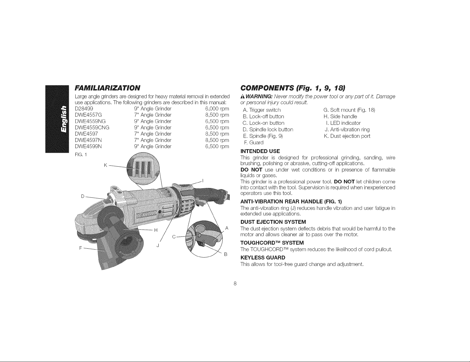
FAMILIARIZATION
Large anglegrinders are designed for heavy material removal in extended
use applications. The following grinders are described in this manual:
D28499 9" Angle Grinder 6,000 rpm
DWE4557G 7" Angle Grinder 8,500 rpm
DWE4559NG 9" Angle Grinder 6,500 rpm
DWE4559CNG 9" Angle Grinder 6,500 rpm
DWE4597 7" Angle Grinder 8,500 rpm
DWE4597N 7" Angle Grinder 8,500 rpm
DWE4599N 9" Angle Grinder 6,500 rpm
FIG.1
COMPONENTS (Fig. 1j 9_ 18)
_, WARNING: Never modify the power tool or any part of it. Damage
or personal injury could result.
A. Trigger switch
B. Lock-off button
C. Lock-on button
D. Spindle lock button
E. Spindle (Fig. 9)
R Guard
INTENDED USE
This grinder is designed for professional grinding, sanding, wire
brushing, polishing or abrasive, cutting-off applications.
DO NOT use under wet conditions or in presence of flammable
liquids or gases.
This grinder is a professional power tool. DO NOT let children come
into contact with the tool. Supervision is required when inexperienced
operators use this tool.
ANTI-VIBRATION REAR HANDLE (FIG. 1}
The anti-vibration ring (J)reduces handle vibration and user fatigue in
extended use applications.
DUST EJECTION SYSTEM
A
The dust ejection system deflects debris that would be harmful to the
motor and allows cleaner air to pass over the motor.
TOUGHCORD TM SYSTEM
The TOUGHCORD TM system reduces the likelihood of cord pullout.
KEYLESS GUARD
This allows for tool-free guard change and adjustment.
G. Soft mount (Fig. 18)
H. Side handle
I. LED indicator
J. Anti-vibration ring
K. Dust ejection port
Page 10

E-SWITCH PROTECTION TM
(DWE4597, DWE4597N, DWE4599N}
The ON/OFF trigger switch has a no-volt releasefunction. Inthe event
of a power outage or other unexpected shut down, the trigger switch
will need to be cycled (turned on and off) to restart tool.
CLUTCH
(DWE4597, DWE4597N, DWE4599N)
The torque limiting clutch reduces the maximum reaction torque
transmitted to the operator in the case of jamming a cutting disc. This
feature also prevents the gearing and electric motor from stalling. The
torque limiting clutch has been factory set and cannot be adjusted.
E-CLUTCH TM
(DWE4597, DWE4597N, DWE4599N)
This unit is equipped with an E-Clutch TM (Electronic Clutch), which
in the event of a high-load or wheel pinch, the unit will be shut off to
reduce the reaction torque to the user. The switch needs to be cycled
(turned on and off) to restart tool.
POWER-OFF MOVERLOAD PROTECTION
(DWE4597, DWE4597N, DWE4599N)
The power supply to the motor will be reduced in case of motor
overload. With continued motor overload, the tool will shut off. The
switch needs to be cycled (turned on and off) to restart tool. The tool
will power off each time the current load reaches the overload current
value (motor burn-up point). If continued overload shutdowns occur,
apply less force/weight on the tool until the tool will function without
the overload engaging.
COMPLETE ELECTRONIC CONTROL TM
(DWE4597, DWE4597N, DWE4599N}
The internal electronic speed control offers consistent wheel speed
while using the tool.
ELECTRONIC SOFT START
(DWE4597, DWE4597N, DWE4599N}
This feature limits the initialstart up momentum, allowing the speed to
build up gradually over a 1 second period.
ASSEMBLY AND ADJUSTMENTS
A WARNING: To reduce the risk of injury, turn unit off
and disconnect ff from power source before installing and
removing accessories, before adjusting or when making
repairs. An accidenta/ start-up can cause injury.
AttacMng Side Handle (Fig. 2)
The side handle (H)can be fitted to either side or the FIG.2
top of the gear case in the threaded holes. The f_'-
side positions are designed for optimized balance
in surface finishing and grinding applications. The
side handle must be used at all times to maintain
proper control of the tool. Before using the tool,
check that the handle is tightened securely.
NOTE: The D28499 offers 5 handle locations for
additional versatility.
ANTI-VIBRATION SIDE HANDLE
(DWE4597, DWE4597N, DWE4599N)
The anti-vibration side handle reduces vibration and user fatigue in
extended use applications.
GEAR CASE GRIP (FIG. 3}
(DWE4559CN, DWE4559CNG)
The DWE4559CN and DWE4559CNG include a soft grip cover for
the gear case that can be used as a gripping surface only for pipeline
grinding and wire brushing where the edge of the wheel is used
for grinding and cleaning and precise control is needed to ensure
accuracy. As with any gripping surface, maintain firm grip during use.
Page 11

Thesidehandleshouldbeusedasthesecondarygripsurfaceforall
otherapplications.
FIG.3 \
Thegearcasegripmaybepurchasedatadditionalcost.Please
call1-800-4-DEWALT(1-800-433-9258)or visit ourwebsite:
www.dewalt.com.
Ro*a*in9 the Gear Case (Fig. 4)
For applications in which a tool will be FIG.4
dedicated for uses in edge grinding and
finishing work, the gear case may be
rotated 90 ° left or right of its original
position.
1. Remove the four corner screws
attaching the gear case to motor
housing.
2. Without separating the gear case from motor housing, rotate the
gear case head to desired position.
NOTE: If the gear case and motor housing become separated
by more than 1/8" (3.17 mm), the tool must be serviced and
re-assembled by a DEiWALTservice center. Failure to have the tool
serviced may cause brush, motor and bearing failure.
3. Reinstall screws to attach the gear case to the motor housing.
Tighten screws to 20 in.-Ibs, torque. Overtightening could cause
screws to strip.
Rotating the Rear Handle (Fig. 5)
(D28499 ONLY} FIG.5
1. Unlock the rear handle by _90o
pulling out the Handle Release
Lever (L).
2. Rotate handle into available 6°°
0°, 30°, 60°, or 90° position
left OR right of center.
3. Push in the handle release
lever.
4. Before turning the tool on, ensure that the handle is locked into a
position and the handle release lever has returned to the original
position flush with the tool housing.
Wheel Mountin9 Accessories and
Attachments
It is important to choose the correct guards, backing pads and
flanges to use with grinder accessories. Refer to pages 11-13 for
information on choosing the correct wheel mounting accessories.
ATTACH MENTS
Attachments designed specifically for this grinder can be
purchased through DEWALT dealers and DEWALT Factory Service
centers.
9" Type 27 guard D284939
9" Type 28 guard D284938
7" Type 27 guard D284937
5"-6" Type 11 flaring cup guard with flange D284936
4" Type 11 flaring cup guard with flange D284934
10
1
Page 12

Type11flaringcupwheelbackingflange
Type1flangeset
7"Type1guard
Grindingbackingflange
Clampnut
Wheelwrench
Softmountspindleprotector
N197992
D284932
D284931
54339-00
22191-00
61820-01
445928-01
i_WARNING: Accessories must be rated for at least the speed
recommended on the tool waming label Wheels and other
accessories running over their rated accessory speed may fly apart
and cause injury. Threaded accessories must have a 5/8"-11 hub.
Every unthreaded accessory must have a 7/8" (22.2 mm) arbor
hole. If it does not, it may have been designed for a circular saw.
Use only the accessories shown on pages 11-13 of this manual.
Accessory ratings must always be above tool speed as shown on
tool nameplate.
Mounting Guard
MOUNTING AND REMOVING GUARD (FIG. 6, 7}
_ WARNING: Guards must be used with all grinding wheels,
cutting wheels, sanding flap discs, wire brushes, and wire
wheels. Guard modification that results in reduced coverage
of the accessory could result in severe personal injury. The too/
may be used without a guard only when sanding with conventional
sanding discs. A Type 27 guard (intended for use with depressed
center grinding wheels [Type 2 7 and Type29], sanding flap discs, wire
wheels and wire cup brushes) is available at extra cost from your local
dealer or authorized service cente_ Grinding and cutting with wheels
other than Type 27 and 29 require different accessory guards not
included with tool A Type 1guard is provided for use with the Type 1
wheel. Mounting instructions for accessory guards are shown below
and are also included in the accessory package.
Sanding Flap Discs
soft mount
445928-01
Type 27 guard
D284937 7"
D284939 9"
hubbed sanding
flap disc
NOTE: Wheel size must match guard size; i.e., a new 7" wheel may
not be used with a 9" guard. The bottom surface of wheel must be
inside the bend of the guard lip.
11
soft mount
445928-01
Type 27 guard
D284937 7"
D284939 9"
backingflange
54339-00
non-hubbed sanding
flap disc
clamp nut
22191-00
Page 13

Grinding Wheels
Sanding Discs
softmount
445928-01
Type27guard
D2849377"
D2849399"
Type27hubbedwheel
softmount
445928-01
Type28guard
D2849389"
Type28hubbedwheel
soR mount
445928-01
Type 27 guard
D284937 7"
D284939 9"
backing flange
54339-00
Type 27 non-hubbed
wheel
clamp nut
22191-00
NOTE: Wheel size must match guard size; i.e., a new 7" wheel may not be used with a 9"
guard. The bottom surface of wheel must be inside the bend of the guard lip.
soR mount
445928-01
Type 28 guard
D284938 9"
backing flange
54339-00
Type 28 non-hubbed
wheel
clamp nut
22191-00
soR mount
445928-01
rubber backing pad
sanding disc
clamp nut
12
Page 14

Wire Wheels
soft mount
445928-01
Type 27 guard
D284937 7"
D284939 9"
Flaring Cup Stones Cutting Wheels
Type 11
flaring cup guard
D284934 4"
D284936 5"-6"
backing flange
N197992
Type 1 guard
D284931
backing flange
N188469
abrasive cutting wheel
backing flange
diamond cutting wheel
Type 1 guard
D284931
N188469
wire cup brush
soft mount
445928-01
Type 27 guard
D284937 7"
D284939 9"
wire wheel
flaring cup stone
NOTE: Wheel size must match guard size; i.e., a 7" wheel
may not be used with a 9" guard.
13
clamp nut
401678-06
clamp nut
401678-06
Page 15

1.Opentheguardlatch(M),andalignthe FIG.6 N
lugs(N)ontheguardwiththeslotson
thegearcase(O).Thiswillalignthelugs M
ontheguardwiththeslotsonthegear
casecover.
2.Pushtheguarddownuntiltheguard
lugsengageandcanrotatefreelyinto
thegrooveonthegearcasehub. O
3.Withtheguardlatchopen,rotatethe
guard(F)intothedesiredworking F
position.Theguardbodyshouldbe
positionedbetweenthespindleandthe
operatortoprovidemaximumoperator
protection.
4.Closetheguardlatchto securethe
guardonthegearcase.Youshould
notbeableto rotatetheguardby
handwhenthelatchisclosed.Donot
operatethegrinderwithalooseguardorwiththeguardlatchin
openposition.
5.Toremovetheguard,followtheprocedureaboveinreverseorder.
NOTE:Theguardispre-adjustedto the FIG.7
diameterofthegearcasehubatthefactory.
If,afteraperiodoftime,theguardbecomes P
loose,tightentheadjustingscrew(P)with
guardlatchintheclosedpositionwithguard
installedonthetool.
_CAUTION: Do not tighten the adjusting
screw with the guard latch in the open
position. Undetectable damage to the guard
or the mounting hub may result.
j_CAUTION: If the guard cannot be tightened by the adjusting
clamp, do not use the tool To reduce the risk of personal injury, take
the tool and guard to a service center to repair or replace the guard.
NOTE: Edge grinding and cutting can be performed with
Type 27 wheels designed and specified for this purpose; 1/4"
(6.35 mm) thick wheels are designed for surface grinding while 1/8"
(3.17 mm) wheels are designed for edge grinding. Cutting can also be
performed by using a Type 1 wheel and a Type 1 guard.
OPERATION
_WARNING: To reduce the risk of injury, turn unit off
and disconnect ff from power source before installing and
removing accessories, before adjusting or when making
repairs. An accidental start-up can cause injury,
Switch (Fig. 8)
i_ CAUTION: Before connecting the tool to a power source or after
a power failure, depress and release the trigger switch (A) once
without depressing the lock-on button (C) to ensure that the switch is
in the off position. If the trigger switch is locked on, the tool will start
unexpectedly when power is reconnected to the tool Hold the side
handle and rear handle firmly to maintain control of tool at start up
and during use.
TRIGGER OPERATION FIG.8
Toturn the tool on, depress lock-off button (B)
then trigger switch (A). The trigger can be
feathered as long as the lock-off button is
depressed. The tool will remain running while
the trigger is depressed. Turn the tool off by
releasing the trigger. B A
14
Page 16
TRIGGER OPERATION WITH LOCK-ON FEATURE
Toturn tool on, depress trigger. Depress and hold lock-on button (C)
while releasing trigger. Lock-on button will remain depressed and tool
will remain on.
To turn the tool off, depress and release trigger. The lock-on button
will pop out, permitting the trigger to disengage and causing the tool
to turn off.
NOTE: Allow the tool to reach full speed before touching tool to work
surface. Lift the tool from the work surface before turning the tool off.
CAUTION: Make sure the wheel has come to a complete stop
before setting the tool down.
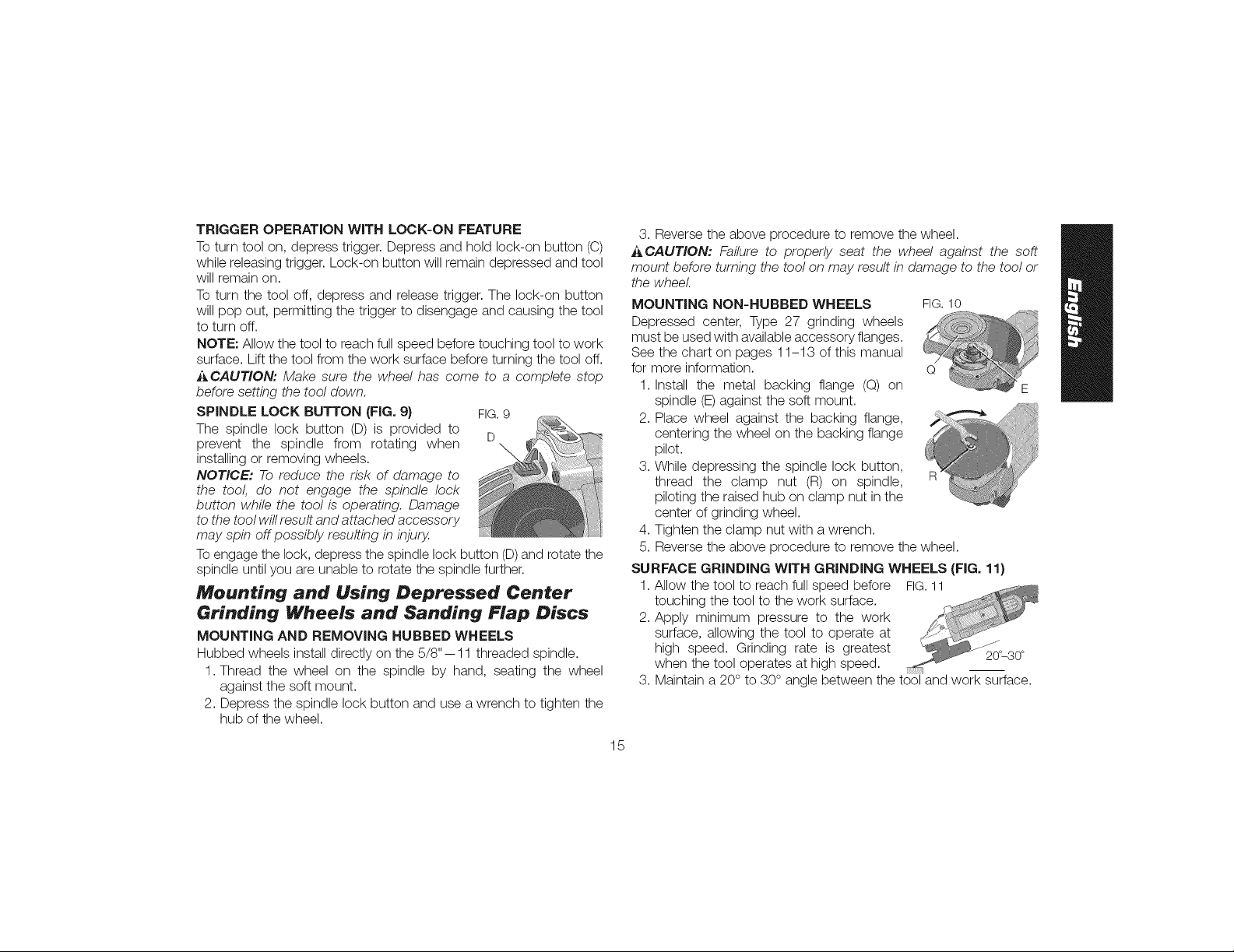
SPINDLE LOCK BUTTON (FIG. 9) FIG.9
The spindle lock button (D)is provided to
prevent the spindle from rotating when D
installing or removing wheels.
NOTICE: To reduce the risk of damage to
the tool, do not engage the spindle lock
button while the tool is operating. Damage
to the tool will result and attached accessory
may spin off possibly resulting in injury.
Toengage the lock, depress the spindle lock button (D)and rotate the
spindle until you are unable to rotate the spindle further.
Mounting and Using Depressed Center
Grinding Wheels and Sanding Flap Discs
MOUNTING AND REMOVING HUBBED WHEELS
Hubbed wheels installdirectly on the 5/8"-- 11 threaded spindle.
1. Thread the wheel on the spindle by hand, seating the wheel
against the soft mount.
2. Depress the spindle lock button and use a wrench to tighten the
hub of the wheel.
3. Reverse the above procedure to remove the wheel.
ACAUTION: Failure to properly seat the wheel against the soft
mount before turning the tool on may result in damage to the tool or
the wheel.
MOUNTING NON-HUBBED WHEELS FIG.10
Depressed center, Type 27 grinding wheels
must be used with available accessory flanges.
See the chart on pages 11-13 of this manual
for more information. Q
1. Install the metal backing flange (Q) on
spindle (E)against the soft mount.
2. Place wheel against the backing flange,
centering the wheel on the backing flange
pilot.
3. While depressing the spindle lock button,
thread the clamp nut (R) on spindle,
piloting the raised hub on clamp nut in the
center of grinding wheel.
4. Tighten the clamp nut with a wrench.
5. Reverse the above procedure to remove the wheel.
SURFACE GRINDING WITH GRINDING WHEELS (FIG. 11}
1. Allow the tool to reach full speed before FIG.11
touching the tool to the work surface.2. Apply minimum pressure to the work
surface, allowing the tool to operate at .......
high speed. Grinding rate is greatest
when the tool operates at high speed. __-_
3. Maintain a 20° to 30° angle between the tool and work surface.
15
20°_30°
Page 17
4.Continuouslymovethetoolinaforwardandbackmotiontoavoid
creatinggougesintheworksurface.
5.Removethetoolfromworksurfacebeforeturningtooloff.Allow
thewheeltostoprotatingbeforelayingthetooldown.
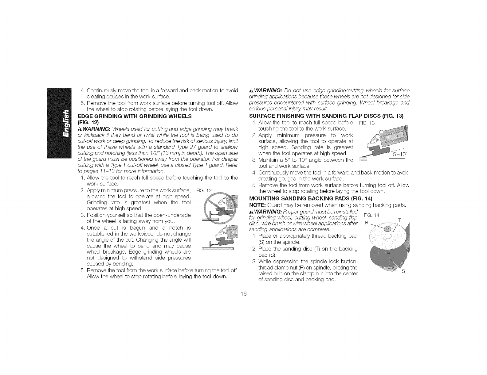
EDGE GRINDING WITH GRINDING WHEELS
(FIG. 12)
i_ WARNING: Wheels used for cutting and edge grinding may break
or kickback if they bend or twist while the tool is being used to do
cut-off work or deep grinding. Toreduce the risk of serious injury, limit
the use of these wheels with a standard Type 27 guard to shallow
cutting and notching (less than 1/2" [13 mm] in depth). The open side
of the guard must be positioned away from the operato_ For deeper
cutting with a Type 1 cut-off wheel, use a closed Type 1 guard. Refer
to pages 11-13 for more information.
1. Allow the tool to reach full speed before touching the tool to the
work surface.
2. Apply minimum pressure to the work surface, FIG. 12
allowing the tool to operate at high speed.
Grinding rate is greatest when the tool
operates at high speed.
3. Position yourself so that the open-underside
of the wheel is facing away from you.
4. Once a cut is begun and a notch is
established in the workpiece, do not change
the angle of the cut. Changing the angle will
cause the wheel to bend and may cause .................................................................a
wheel breakage. Edge grinding wheels are
not designed to withstand side pressures
caused by bending.
5. Remove the tool from the work surface before turning the tool off.
Allow the wheel to stop rotating before laying the tool down.
_ WARNING: Do not use edge grinding/cutting wheels for surface
grinding applications because these wheels are not designed for side
pressures encountered with surface grinding. Wheel breakage and
serious personal injury may result.
SURFACE FINISHING WITH SANDING FLAP DISCS (FIG. 13)
1. Allow the tool to reach full speed before FIG.13
touching the tool to the work surface.
2. Apply minimum pressure to work
surface, allowing the tool to operate at
high speed. Sanding rate is greatest
when the tool operates at high speed.
3. Maintain a 5° to 10° angle between the
tool and work surface.
4. Continuously move the tool in a forward and back motion to avoid
creating gouges in the work surface.
5. Remove the tool from work surface before turning tool off. Allow
the wheel to stop rotating before laying the tool down.
MOUNTING SANDING BACKING PADS (FIG. 14)
NOTE: Guard may be removed when using sanding backing pads.
i_ WARNING: Proper guard must be reinstalled
for grinding wheel, cutting wheel, sanding flap FIG.14
disc, wire brash or wire wheel applications after R T
sanding applications are complete.
1. Place or appropriately thread backing pad
(S)on the spindle.
2. Place the sanding disc (7) on the backing
pad (S).
3. While depressing the spindle lock button,
thread clamp nut (R)on spindle, piloting the
raised hub on the clamp nut into the center
of sanding disc and backing pad.
16
Page 18

4.Tightentheclampnutbyhand.Thendepressthespindlelock
buttonwhileturningthesandingdiscuntilthesandingdiscand
clampnutaresnug.
5.Toremovethewheel,graspandturnthebackingpadand
sandingdiscwhiledepressingthespindlelockbutton.
USING SANDING BACKING PADS (FIG. 15)
Choose the proper grit sanding discs for your application. Sanding
discs are available in various grits. Coarse grits yield faster material
removal rates and a rougher finish. Finer grits yield slower material
removal and a smoother finish.
Begin with coarse grit discs for fast, rough material removal. Move to
a medium grit paper and finish with a fine grit disc for optimal finish.
Coarse 16-30 grit
Medium 36-80 grit
Fine Finishing 100-120 grit
Very Fine Finishing 150 180 grit
1. Allow the tool to reach full speed before touching tool to the work
surface.
2. Apply minimum pressure to work surface, allowing the tool to
operate at high speed. Sanding rate is greatest when the tool
operates at high speed.
3. Maintain a 5° to 15° angle between the tool and work surface.
The sanding disc should contact approximately 1" (25.4 mm) of
work surface.
4. Move the tool constantly inastraight line FIG.15
to prevent burning and swirling of work
surface. Allowing the tool to rest on the
work surface without moving, or moving
the tool in a circular motion causes 5°-15°
burning and swirling marks on the work
surface.
5. Remove the tool from work surface before turning tool off. Allow
the wheel to stop rotating before laying the tool down.
Precautions To Take When Sanding Paint
1. Sanding of lead based paint is NOT RECOMMENDED due to
the difficulty of controlling the contaminated dust. The greatest
danger of lead poisoning is to children and pregnant women.
2. Since it is difficult to identify whether or not a paint contains
lead without a chemical analysis, we recommend the following
precautions when sanding any paint:
PERSONAL SAFETY
1. No children or pregnant women should enter the work area
where the paint sanding is being done until all clean up is
completed.
2. A dust mask or respirator should be worn by all persons entering
the work area. The filter should be replaced daily or whenever the
wearer has difficulty breathing.
NOTE: Only those dust masks suitable for working with lead paint
dust and fumes should be used. Ordinary painting masks do not
offer this protection. See your local hardware dealer for the proper
NIOSH-approved mask.
3. NO EATING, DRINKING or SMOKING should be done inthe work
area to prevent ingesting contaminated paint particles. Workers
should wash and clean up BEFORE eating, drinking or smoking.
Articles of food, drink, or smoking should not be left in the work
area where dust would settle on them.
ENVIRON M ENTAL SAFETY
1. Paint should be removed in such a manner as to minimize the
amount of dust generated.
2. Areas where paint removal is occurring should be sealed with
plastic sheeting of 4 mils thickness.
17
Page 19

3.Sandingshouldbedoneinamannertoreducetrackingofpaint
dustoutsidetheworkarea.
CLEANING AND DISPOSAL
1. All surfaces in the work area should be vacuumed and thoroughly
cleaned daily for the duration of the sanding project. Vacuum filter
bags should be changed frequently.
2. Plastic drop cloths should be gathered up and disposed of
along with any dust chips or other removal debris. They should
be placed in sealed refuse receptacles and disposed of through
regular trash pick-up procedures.
During clean up, children and pregnant women should be kept
away from the immediate work area.
3. All toys, washable furniture and utensils used by children should
be washed thoroughly before being used again.
Mounting and Using Wire Brushes
and Wire Wheels
Wire cup brushes or wire wheels screw directly on the grinder spindle
without the use of flanges. Use only wire brushes or wheels provided
with a 5/8"-11 threaded hub. AType 27 guard is required when using
wire brushes and wheels.
CAUTION: To reduce the risk of personal injury, wear work
gloves when handling wire brushes and wheels. They can
become sharp.
A CAUTION: To reduce the risk of damage to the tool, wheel or
brush must not touch guard when mounted or while in use.
Undetectable damage could occur to the accessory, causing wires to
fragment from accessory wheel or cup.
MOUNTING WIRE CUP BRUSHES AND WIRE WHEELS
1. Thread the wheel on the spindle by hand.
2. Depress spindle lock button and use a wrench on the hub of the
wire wheel or brush to tighten the wheel.
3. To remove the wheel, reverse the above procedure.
NOTICE: To reduce the risk of damage to the tool, properly seat the
wheel hub before turning the tool on.
USING WIRE CUP BRUSHES AND WIRE WHEELS (FIG. 16}
Wire wheels and brushes can be used for removing rust, scale and
paint, and for smoothing irregular surfaces.
NOTE: The same precautions should be taken when wire brushing
paint as when sanding paint (refer to Precautions To Take When
Sanding Paint).
1. Allow the tool to reach full speed before touching the tool to the
work surface.
2. Apply minimum pressure to work surface, allowing the tool to
operate at high speed. Material removal rate is greatest when the
tool operates at high speed.
3. Maintain a 5° to 10° angle between the tool and work surface
for wire cup brushes.
4. Maintain contact between the edge of the wheel and the work
surface with wire wheels.
5. Continuously move the tool in a forward and FIG.16
back motion to avoid creating gouges in
the work surface. Allowing the tool to rest
on the work surface without moving, or
moving the tool in a circular motion causes
burning and swirling marks on the work
surface.
6. Remove the tool from the work surface before turning the tool off.
Allow the tool to stop rotating before setting it down.
_,CAUTION: Use extra care when working over an edge, as a
sudden sharp movement of grinder may be experienced.
18
Page 20

Mounting and Using Flaring Cup
(Type 11) Wheel
MOUNTING FLARING CUP WHEEL GUARD (FIG. 17)
i_ WARNING: The flaring cup wheel guard is not included with
this tool. F/aring cup wheels require proper flanges and guards. 4"
flaring cup wheel guard D284934 and 5"- 6" flaring cup wheel guard
D284936 are available as accessories and include proper flange.
Failure to use the proper flange and guard canresult in injury resulting
from wheel breakage and wheel contact. FIG.17
1. Install the guard as shown in Fig. 17.
2. Guard body should be positioned between U
the spindle and the operator to provide
maximum operator protection.
3. Securely tighten the two clamping screws
(U) supplied with the guard.
MOUNTING FLARING CUP WHEEL (FIG. 18}
1. Remove the soft mount (G).
2. Install the flaring cup wheel backing flange, aligning the flats on
the spindle (V) with the flats on backing flange (Q).
3. Thread the flaring cup wheel on spindle by hand, seating wheel
against backing flange.
4. Depress the spindle lock button and tighten the wheel by hand.
5. To remove the wheel, reverse the above procedure.
FIG. 18
j_CAUTION: Fa//ure to properly seat the wheel against backing
flange before turning the tool on may result in damage to the tool or
the wheel.
NOTE: Adjust the guard skirt so that only 1/8" of the wheel is
exposed by loosening the bolts, allowing the guard to lengthen.
Tighten the guard skirt bolts securely before using the grinder.
USING A FLARING CUP WHEEL (FIG, 19)
Flaring cup wheels are designed for heavy material removal.
1. Allow the tool to reach full speed before FIG.19
touching tool to work surface.
2. Apply minimum pressure to work
surface, allowing the tool to operate at
high speed. ..........5_10°
3. Maintain a 5°to 10°angle between the
tool and the work surface.
4. Continuously move the tool in a forward and back motion to avoid
creating gouges in the work surface.
5. Remove the tool from work surface before turning tool off. Allow
the tool to stop rotating before setting it down.
Mounting and Using Cutting
(Type 1) Wheels (Fig. 20_ 21)
Cutting wheels includediamond wheels and abrasive discs. Abrasive
cutting wheels for metal and concrete use are available. Diamond
blades for concrete cutting can also be used.
_ WARNING: A closed, two-sided cutting wheel guard is included
with this tool and is required when using cutting wheels. Failure to
use proper flange and guard can result in injury resulting from wheel
breakage and wheel contact. See pages 11-13 for more information.
19
Page 21

MOUNTINGCLOSED(TYPE1)GUARD FIG,20 _N
1. Open the guard latch (M), and align the M
lugs (N) on the guard with the slots on
the hub (O). This will align the lugs with
slots on the gear case cover. Position
the guard facing backward.
2. Push the guard down until the guard
lug engages and rotates freely in the O
groove on the gear case hub.
3. Rotate guard (F) into desired working F
position. The guard body should be
positioned between the spindle and the
operator to provide maximum operator
protection.
4. Close the guard latch to secure the
guard on the gear case cover. You
should be unable to rotate the guard
by hand when the latch is in closed
position. Do not operate grinder with a
loose guard or with the guard latch in
open position.
5. To remove the guard, follow the procedure above in reverse order.
NOTE" The guard is pre-adjusted to the FIG.21
diameter of the gear case hub at the factory. P
If, after a period of time, the guard becomes
loose, tighten the adjusting screw (P) with
the guard latch in the closed position with
guard installed on the tool.
NOTICE: To reduce the risk of damage
to the tool, do not tighten adjusting screw with guard latch in open
position. Undetectable damage to guard or mounting hub may result.
MOUNTING CUTTING WHEELS (FIG. 22)
CAUTION: Matching diameter threaded backing flange and clamp
nut (included with tool) must be used for cutting wheels.
1. Remove soft mount (G).
2. Install wheel backing flange, aligning flats on spindle (X)with flats
on backing flange (Q).
3. Place the wheel on the backing flange, centering the wheel on
the backing flange pilot.
4. Install the clamp nut, ensuring that the wheel remains centered
on the backing flange.
5. Depress the spindle lock button and tighten clamp nut with
wrench.
6. Reverse the above procedure to remove the wheel.
FIG.22
USING CUTTING WHEELS
i_,WARNING: Do not use edge grinding/cutting wheels for surface
grinding applications because these wheels are not designed for side
pressures encountered with surface grinding. Wheel breakage and
injury may result.
1. Allow tool to reach full speed before touching tool to work
surface.
2. Apply minimum pressure to work surface, allowing tool to operate
at high speed. Cutting rate is greatest when the tool operates at
high speed.
2O
Page 22

3.Onceacutisbegunandanotchisestablishedintheworkpiece,
donotchangetheangleofthecut.Changingtheanglewillcause
thewheeltobendandmaycausewheelbreakage.
4.Removethetoolfromworksurfacebeforeturningtooloff.Allow
thewheeltostoprotatingbeforelayingthetooldown.
MAINTENANCE
_WARNING: To reduce the risk of injury, turn unit off
and disconnect it from power source before installing and
removing accessories, before adjusting or when making
repairs. An accidental start-up can cause injury.
Cleaning
WARNING: Blow dirt and dust out of all air vents with clean, dry air
at least once a week. To minimize the risk of eye injury, always wear
ANSI Z87.1 approved eye protection when performing this.
i_ WARNING: Never use solvents or other harsh chemicals for
cleaning the non-metallic parts of the tool These chemicals may
weaken the plastic materials used in these parts. Use a cloth
dampened only with water and mild soap. Never let any liquid get
inside the tool,"never immerse any part of the tool into a liquid.
Accessories
_WARNING: Since accessories, other than those offered by
DEWALT, have not been tested with this product, use of such
accessories with this tool could be hazardous. To reduce the risk of
injury, only DEWALT recommended accessories should be used with
this product.
BAIL HANDLE
This accessory provides a wider range of holding positions when
grinding and is particularly useful when surface grinding concrete.
ANTI-VIBRATION SIDE HANDLE
The anti-vibration side handle reduces vibration and user fatigue in
extended use applications.
GEAR CASE GRIP
The gear case grip is a soft grip cover used only for pipeline grinding
and wire brushing where the edge of the wheel is used for grinding
and cleaning and precise control is needed to ensure accuracy.
Recommended accessories for use with your tool are available at
extra cost from your local dealer or authorized service center. If you
need assistance in locating any accessory, please contact DEWALT
Industrial Tool Co., 701 East Joppa Road, Baltimore, MD 21286,
call 1-800-4-DE.:.WALT(1-800-433-9258) or visit our website: www.
dewalt.com.
Repairs
To assure product SAFETY and RELIABILITY, repairs, maintenance
and adjustment (including brush inspection and replacement) should
be performed by a DEiWALT factory service center, a DEWALT
authorized service center or other qualified service personnel. Always
use identical replacement parts.
Register Online
Thank you for your purchase. Register your product now for:
,, WARRANTY SERVICE: Registering your product will help you
obtain more efficient warranty service in case there is a problem
with your product.
, CONFIRMATION OF OWNERSHIP: In case of an insurance
loss, such as fire, flood or theft, your registration of ownership will
serve as your proof of purchase.
21
Page 23
• FOR YOUR SAFETY: Registering your product will allow us to
contact you in the unlikely event a safety notification is required
under the Federal Consumer Safety Act.
Register online at www.dewalt.com/register.
Three Year Limited Warranty
DE.:.WALTwill repair,without charge, any defects due to faulty materials
or workmanship for three years from the date of purchase. This
warranty does not cover part failure due to normal wear or tool
abuse. For further detail of warranty coverage and warranty repair
information, visit www.dewalt.com or call 1-800-4-DEWALT (1-800-
433-9258). This warranty does not apply to accessories or damage
caused where repairs have been made or attempted by others. This
warranty gives you specific legal rights and you may have other rights
which vary in certain states or provinces.
In addition to the warranty, DEWALT tools are covered by our:
1 YEAR FREE SERVICE
DEWALT will maintain the tool and replace worn parts caused by
normal use, for free, any time during the first year after purchase.
90 DAY MONEY BACK GUARANTEE
If you are not completely satisfied with the performance of your
DEWALT Power Tool, Laser, or Nailer for any reason, you can return
it within 90 days from the date of purchase with a receipt for a full
refund - no questions asked.
LATIN AMERICA: This warranty does not apply to products sold
in Latin America. For products sold in Latin America, see country
specific warranty information contained in the packaging, call the local
company or see website for warranty information.
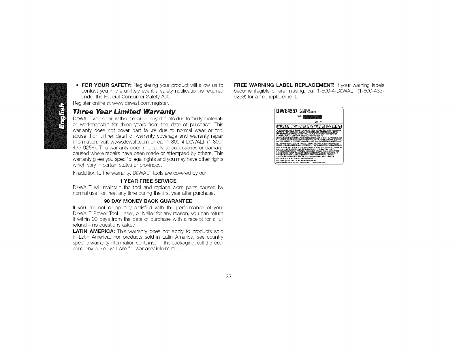
FREE WARNING LABEL REPLACEMENT: If your warning labels
become illegible or are missing, call 1-800-4-DE.:.WALT(1-800-433-
9258) for a free replacement.
_WE4557 " .... )
TO_EDUCETHE_ISKOFI,_U_Y.USeRmUSTR_A,,NST_UC_ON_A_UALALWAYS
WEAR_Y_P_OT_O_.US_ONLYACCESSORIES_TEOATL_STEO0_TOT_E
MAXIMUMSPEEDMA_KEDONTH_TOOLA_WAYSUSEPRO_ 0UAR_SW_EN
OE_SlO._S.SI_r_ _LEVE_O_ECCl0_OCULar.SOlO_TIUC__C_ESO_0SCOW
VELOCIOA_) NOMiNA_ SE_ A_ M_N_S E_UIVALENTE A _ VE_0;iBAO MAXIMA INOICABA
_CC_SS0_.ESOONTL_VI_SSE_O_IN_L__S_EOU_V_LE_EOUSUPE_IEU_
CELLEINO_(_U_ESUR L'OOTILUTILISERSy_TE_IATII_UEME_TDESC_RTE_S
ANGLE GAINDER
SEN.
5/8"- 11
22
Page 24

D_finitions : Iignes directrices en
rnati_re de s_curit_
Les definitions ci-dessous decrivent le niveau de danger pour
chaque mot-indicateur employe. LiFe le mode d'emploi et
porter une attention particuliere _.ces symboles.
J_DANGER : indique une situation dangereuse imminente qui,
si elle n'est pas evitee, entrainera la mort ou des blessures
graves.
_AVERTISSEMENT : indique une situation potentie//ement
dangereuse qui, si e//e n'est pas evitee, pourraff entra?ner /a
mort ou des blessures graves.
J_ATTENTION : indique une situation potentie//ement
dangereuse qui, si e//en'est pas evitee, pourraff entra?nerdes
blessures I_g_res ou mod_r6es.
AVIS : indique une pratique ne posant aucun risque de
dommages corporels mais qui par contre, si rien n'est fair
pour I'evited pourrait poser des risques de dommages
materiels.
POUR TOUTE QUESTION OU REMARQUE AU SUJET DE OET
OUTIL OU DE TOUT AUTRE OUTIL DE.-:WALT,COMPOSEZ LE
NUMC:RO SANS FRAIS : 1-800-4-DEWALT (1-800-433-9258}.
_ VERTISSEMENT : afin de reduire le risque de blessures, /ire
le mode d'emploi de I'outil.
Aver*issernents de s_curit_ g_n_raux
pour les outils _lectriques
_ AVERTISSEMENT ! LiFe tousles avertissements de
s6curit_ et toutes les directives. Le non-respect des
avertissements et des directives pourrait se solder par un choc
dectrique, un incendie et/ou une blessure grave.
CONSERVER TOUSLES AVERTISSEMENTS
ET TOUTES LES DIRECTIVES POUR UN
USAGE ULTERIEUR
Le terme _outi/ dectrique _ cite dans /es avertissements se rappole
votre outil dectrique a a/imentation sur secteur (avecfil) ou par piles
(sans fil).
1} S#CURIT# DU LIEU DE TRAVAIL
a) Tenir I'aire de travail propre et bien 6clair6e. Les /ieux
encombres ou sombres sont propices aux accidents.
b) Ne pas faire fonctionner d'outils 61ectriques clans un
milieu d_flagrant, tel qu'en pr6sence de liquides, de
gaz ou de poussi_res inflammables. Les outi/s dectriques
produisent des etincelles qui pourraient enflammer la poussiere
ou les vapeurs.
c) Eloigner les enfants et les personnes b proximit6 pendant
I'utilisation d'un outi! 61ectrique. Une distraction pourrait en
faire perdre la ma?trisea I'utilisateu_
2) SECURIT# EN MATIERE D'I'--LECTRICITE
a) Les fiches des outils _lectriques doivent correspondre
la prise. Ne jamais modifier la fiche d'aucune faqon.
Ne jamais utiliser de fiche d'adaptation avec un outil
61ectrique mis _ la terre. Le risque de choc dectrique sera
reduit par/'uti/isation de fiches non modifiees correspondant
la prise.
23
Page 25

b)Evitertoutcontactphysiqueavecdessurfacesmisesbla
tortecommedestuyaux,desradiateurs,descuisini_res
etdesr6frig6rateurs.Lerisquedechocdectriqueestp/us
devesivotrecorpsestmisalaterre.
c)Nepasexposerlosoutils61ectriques b la pluie ou b
I'humidit_. La penetration de /'eau dans un outi/ dectrique
augmente le risque de choc dectrique.
d) Ne pas utiliser le cordon de faqon abusive. Ne jamais
utiliser le cordon pour transporter, tirer ou d_brancher
un outil 61ectrique. Tenir le cordon 61oign_ de la chaleur,
de I'huile, des bords tranchants et des pi_ces mobiles.
Les cordons endommages ou enchev6tres augmentent /es
risques de choc dectrique.
e) Pour I'utilisation d'un outil 61ectrique b I'ext_rieur, se
servir d'une rallonge convenant _ cette application.
L'utilisation d'une rallonge conque pour I'exterieur reduira les
risques de choc dectrique.
f) S'il est impossible d'6viter I'utilisation d'un outil
61ectrique clans un endroit humide, brancher I'outil clans
une prise ou sur un circuit d'alimentation dot6s d'un
disjoncteur de fuite _ la torte (GFCI). L'uti/isation de ce type
de disjoncteur reduit /es risques de choc dectrique.
3} SECURITi_ PERSONNELLE
a) Etre vigilant, surveiller le travail effectu_ et faire preuve
de jugement Iorsqu'un outil 61ectrique est utilis6. Ne
pas utiliser d'outil 61ectrique en cas de fatigue ou sous
I'influence de drogues, d'alcool ou de m_dicaments. Un
simple moment d'inattention en uti/isant un outi/ dectrique pout
entra_ner des blessures corpore//es graves.
b) Utiliser des 6quipements de protection individuelle.
Toujours porter une protection oculaire. L'uti/isation
d' equipements de protection comme un masque antipoussiere,
des chaussures antiderapantes, un casque de securite ou des
protecteurs auditifs Iorsque la situation le requiert reduira les
risques de blessures corporelles.
c) Emp@cher los d_marrages intempestifs. S'assurer que
I'interrupteur se trouve _ la position d'arr@t avant de
relier I'outil _ une source d'alimentation et/ou d'ins6rer
un bloc-piles, de ramasser ou de transporter I'outiL
Transporter un outi/ e/ectrique a/ors que /e doigt repose sur
I'interrupteur ou brancher un outil dectrique dont I'interrupteur
est a la position de mamhe risque de provoquer un accident.
d) Retirer toute cl6 de r6glage ou cl_ avant de d_marrer
I'outiL Une cle ou une cle de reglage attachee a une pattie
pivotante de I'outil dectrique peut pmvoquer des blessures
corporelles.
e) Ne pas trop tendre los bras. Conserver son 6quilibre en
tout temps. Ce/apermet de mieux ma?triser /'outi/ dectrique
clans los situations irnprevues.
f) S'habiller de mani_re appropri6e. Ne pas porter de
v@tements amples ni de bijoux. Garder los cheveux, los
v@tements et los gants b 1'6cart des pi_ces mobiles. Les
v6tements amples, les bijoux ou les cheveux longs risquent de
rester coinces dans les pieces mobiles.
g) Si des composants sont fournis pour le raccordement de
dispositifs de d_poussi6rage et de ramassage, s'assurer
que ceux-ci sont bien raccord_s et utilis6s. L'uti/isation
d'un dispositif de depoussierage peut reduire /es dangers
engendres par les poussieres.
4) UTILISATION ET ENTRETIEN D'UN OUTIL ¢:LECTRIOUE
a) Ne pas forcer un outi161ectrique. Utiliser I'outil _lectrique
appropri_ & I'application. L'outil dectrique approprie
effectuera un meilleur travail, de faqon plus sore eta la vitesse
pour laquelle il a ere conqu.
24
Page 26

b)Nepasutiliserunoutil61ectrique dent I'interrupteur
est d_fectueux. Tout outi/ dectrique dent /'interrupteur est
defectueux est dangereux et dolt 6tre repare.
c) D6brancher la fiche de la source d'alimentation et/ou du
bloc-piles de I'outil 61ectrique avant de faire tout r6glage
ou changement d'accessoire ou avant de ranger I'outiL
Ces mesures preventives reduisent /es risques de demarrage
accidentel de I'outil dectrique.
d) Ranger los outils 61ectriques hers de la port6e des
enfants et ne permettre _ aucune personne n'6tant
pas famili_re avec un outil 61ectrique ou son mode
d'emploi d'utiliser cet outiL Les outl/s dectrlques devlennent
dangereux entre los mains d'utl/lsateurs lnexperlmentes.
e) Entretien des outils 61ectriques. V6rifier si les pi&ces
mobiles sent mal align6es ou coinc_es, si des pi_ces sent
bris6es ou pr6sentent toute autre condition susceptible
de nuire au ben fonctionnement de I'outil 61ectrique.
En cas de dommage, faire r6parer I'outil 61ectrique
avant toute nouvelle utilisation. Beaucoup d'accldents sent
causes par des outils dectriques mal entretenus.
f) S'assurer que los outils de coupe sent aiguis6s et
propres. Les outi/s de coupe bien entretenus et affOtes sent
moins susceptibles de se coincer et sent plus faciles a ma_trise_
g) Utiliser /'outil 61ectrique, los accessoires, los forets,
etc. conform6ment aux pr_sentes directives en tenant
compte des conditions de travail et du travail _ effectuer.
L'utilisation d'un outil dectrique pour toute operation autre que
celle pour laquelle il a ere conquest dangereuse.
5) R#PARATION
a) Faire r6parer I'outil 61ectrique par un r6parateur
professionne/ en n'utilisant que des pi_ces de rechange
identiques. Cola permettra de malntenlr une utl/lsatlon
securltalre de/'outl/dectrlque.
CONSIGN£S DE SECURITE POUR
TOUTES L£S OPERATIONS
Aver_issernents de s_curit_ comrnuns
routes les operations de rneulagej
pon_;age_ brossage _ raide d_une brosse
rn_talliquej poHssage ou de coupe
a) Cet outil 61ectrique est conqu pour fonctionner comme
une meule, une ponceuse, une brosse m6tallique,
une polisseuse ou un outil de coupe. Lire tous
los avertissements de s_curit_, los directives, les
illustrations et los sp6cifications fournies avec cet outil
61ectrique. Neg/lger de suivre /'ensemble des directives
suivantes pourrait entra_ner des risques de choc dectrique,
d'incendie et/ou de blessures graves.
b) Ne pas utiliser d'accessoire non conqu sp_cifiquement
pour cet outil ou qui n'auraff pas requ une approbation
sp6cifique du fabricant de I'outiL En effet, l/ est patrols
possible de fixer un accessolre a /'outl/ dectrlque; toutefols,
ce/a ne garantit pas une utilisation securitaire.
c) Le r6gime nominal de Faccessoire dolt @tre au moins
6gal au r6gime maximal inscrit sur I'outil 61ectrique. Los
accessoires soumis a un regime plus deve que ce/ui pour
lequel ils sent conqus peuvent se briser et 6tre projetes.
25
Page 27

d)Le diam_tre externe et 1'6paisseur de I'accessoire doivent
@tre ad_quats pour la capacit6 de I'outil 61ectrique. //est
impossible de proteger /'uti/isateur d'un bris d'accessoire de
mauvais calibre ou de le ma_triser correctement.
e) Le trou pour arbre d'entrainement des meules, brides,
tampons ou de tout autre accessoire dolt s'ajuster
correctement _ la broche de I'outil 61ectrique; autrement,
/'outi/ sera desequi/ibre, vibrera excessivement et risquerait de
provoquer une perte de ma_trise.
f) Ne jamais utiliser un accessoire endommag6. Avant
toute utilisation, inspecter la meule abrasive b la
recherche d'6clats et de fissures; le tampon pour tout
signe de fissures, d_chirures ou d'usure excessive;
et la brosse m6tallique, pour d6celer s'il y a des ills
m6tailiques fissur6s ou d6tach6s. En cas de chute de
I'outil ou de I'accessoire, los inspecter b la recherche de
dommages ou insurer un accessoire non endommag_.
Apr_s I'inspection et I'insertion d'un accessoire, se
positionner (l'utilisateur ou quiconque aux alentours)
hors du plan de rotation de I'accessoire et faire tourner,
pendant une minute, I'outil 61ectrique & plein r6gime, &
vide. Normalement, tout accessoire endommage se brisera au
cours de cette periode d'essaL
g) Porter un 6quipement de protection individuelle. Utiliser
un masque facial, des lunettes de s_curit_ ou des
lunettes protectrices en fonction de I'application.
Au besoin, porter un masque antipoussi_res, des
protecteurs auditifs, des gants et un tablier d'atelier
capable d'arr@ter de petits fragments d'abrasifs ou
de pi_ces. La protection ocu/aire doit 6tre en mesure
d'arr6ter tout debris produit par les diverses operations et le
masque antipoussieres ou le respirateud de flitter les particules
produites par/'operation en cours. Une exposition prolongee
un bruit d'intensite devee pourrait causer une perte auditive.
h) Eloigner tout observateur _ une distance s6curitaire de
la zone de travail. Toute personne qui p6n_tre clans la
zone de travail devra 6galement porter un 6quipement
de protection individueile. // est possib/e qu'un fragment
de piece ou un accessoire brise soit projete et provoque des
blessures au-dela de la zone immediate de travail.
i) Tenir I'outil 61ectrique uniquement par sa surface de
prise isol_e clans une situation ob I'accessoire de coupe
pourraff entrer en contact avec un cable 61ectrique
dissimul6 ou avec son propre cordon d'alimentation.
Tout contact de I'organe de coupe avec un fi/ sous tension
mettra les parties metalliques exposees de I'outil dectrique
sous tension et dectrocutera I'utilisateu_
j) Positionner le cordon d'alimentation hors d'atteinte de
I'accessoire en mouvement. En cas de porte de mattrise, i/
est possible de couper ou d' effilocher le cordon et la main ou le
bras de I'utilisateur risqueraient d'6tre happes par I'accessoire
en mouvement.
k) Nejamais d_poser I'outil 61ectrique avant I'immobilisation
complete de I'accessoire. L'accessoire en mouvement
risquerait de mordre clans /a surface et de projeter /'outi/
dectrique.
I) Mettre I'outil hors tension pour tout d_placement
de celui-ci par I'utilisateur. Un contact accidente/ avec
/'accessoire en mouvement pourrait happer /es v6tements de
I'operateur et projeter I'accessoire contre son corps.
m)Nettoyer r6guli_rement los 6vents de I'outil 61ectrique.
Le ventilateur du moteur aspirera la poussiere a I'interieur du
bo?tie_ Une accumulation excessive de poudre metallique
represente un danger d'origine dectrique.
26
Page 28

n)NepasfairefonctionnerI'outil61ectrique b proximit6 de
mati_res inflammables. Les etince//es produites risquent de
los enf/amme_
o) Ne pas utiliser d'accessoires qui exigent I'utilisation
d'un liquide de refroidissement. L'utilisation d'eau ou de
tout autre /iquide de refroidissement pourrait se solder par une
dectrocution ou une secousse dectrique.
Rebonds eft avertissernents all, rents
L'effet de rebond est une reaction soudaine d'une meu/e,
d'un tampon, d'une brosse ou d'un tout autre accessoire, en
mouvement, qui est pince ou qui s'accmche. Un pincement
ou un accrochage provoque un arr6t rapide de I'accessoire en
mouvement qui, a son tout', projette I'outil dectrique, hors de
ma_trise, dans la direction opposee a la rotation de I'outil au point
de grippage.
Par exemple, si une meule abrasive se pince ou s'accroche dans
la piece, lebord de la meule introduite au point de pincement peut
mordre dans la surface de la piece et projeter la meule hors de
la rainure. La meule peut 6tre projetee vet'sI'operateur ou dans la
direction opposee selon le sens de rotation de la meule au point
de pincement. IIest egalement possible que les meules abrasives
se brisent dans ces conditions.
Les rebonds proviennent d'une utilisation inadequate de I'outil
dectrique et/ou d'une procedure ou de conditions d'utilisation
incorrectes, et peuvent 6tre evites en prenant les precautions
appropriees detaillees ci-apres :
a) Saisir fermement I'outil 61ectrique et positionner le
corps et les bras de sorte b r6sister _ la force de I'effet
de rebond. Utiliser toujours la poign6e auxiliaire, s'il y
en a une, pour contr61er au maximum I'effet de rebond
ou le couple de r6action au d_marrage. Avec de bonnes
precautions, I'operateur est en mesure de contrder le couple
de reaction ou I'effet de rebond.
b) Ne jamais placer los mains pros de I'accessoire en
mouvement. //pourrait en effet 6tre projete sur ce//es-ci en
cas de rebond.
c) Ne pas positionner le corps clans la trajectoire probable
de I'outil 61ectrique, en cas de rebond. Au moment du
grippage, /'outil sera projete clans /a direction opposee au
deplacement de la meule.
d) Etre particuli_rement attentif lots de travaux clans un
coin, sur des bords tranchants, etc. Eviter de faire
rebondir I'accessoire. Eviter tout type de grippage
de I'accessoire. Un travail dans un coin ou sur des bords
tranchants ou un travail en faisant rebondir I'accessoire
pmvoquent souvent un grippage et une perte de ma?trise de
I'outil ou un effet de rebond.
e) Ne pas fixer de lame de tronqonneuse pour sculpter
le bois ou de lame de scie dent_e. Ces types de lames
provoquent des effets de rebond et des pertes de ma?trise
frequents.
Avertissements de s_curit_ sp_cifiques
aux operations de rneulage et de coupe
par abrasion
a) Utiliser uniquement les types de meules recommand_s
pour I'outil 61ectrique ainsi que le capot protecteur
particulier conqu pour la meule s61ectionn6e. // est
impossible de bien proteger I'operateur lots de I'utilisation de
meules non conques pour I'outil. En effet, le capot pmtecteur
sera alors inadequat et I'utilisation de la meule, dangereuse.
27
Page 29

b) fl faut fixer solidement le capot protecteur _ I'outil
61ectrique et le positionner pour maximiser la s_curit6
de I'op6rateur, soit en minimisant la surface expos_e
de la meule en direction de I'op6rateur. Le carter aide
proteger I'utilisateur contre toute projection de fragments et
contre tout contact accidentel avec la meule, ainsi que de toute
etincelle pouvant enflammer les v6tements.
c) Utiliser uniquement los meules pour les applications
pr6vues pour chacune d'entre elles. Par exemple : ne
pas meuler avec le bord d'une meule tronqonneuse.
Les meu/es tronqonneuses par abrasion sont conques pour
travailler en peripherie. L'application de fomes laterales sur ces
meules risquerait de les faire eclate_
d) Toujours utiliser des brides de meule intactes, de la
bonne dimension et de la forme appropri6e pour la meule
s61ectionn6e. Les brides de meule appropriees supportent
bien la meule et reduisent ainsi la possibilite d'un bris de meule.
Les brides conques pour les meules tronqonneuses pourraient
differer des brides pour meules a ponqage.
e) Ne pas utiliser de meule us_e en provenance d'outil de
dimension plus importante. Ces meules, prevues pour un
outil dectrique plus grand, ne conviennent pas au regime plus
deve d'un outil de plus petite dimension et pourraient eclate_
Avertissernents de s_curit_
suppl_rnentaires sp_cifiques aux
operations de coupe par abrasion
a) Ne pas ,, coincer , la meule tronqonneuse ou ne pas
appliquer une pression excessive. Ne pas essayer de
couper _ une profondeur trop importante. Une contrainte
excessive sur /a meu/e accro?tra /a charge et /a possibi/ite de
tordre ou de gripper la meule clans le trait de coupe et ainsi
provoquer un effet de rebond ou un bris de la meule.
b) Ne pas positionner le corps sur la trajectoire de la meule
en mouvement ni derriere celle-cL Lorsque /a meu/e,
au point de contact avec la piece, s'doigne du corps de
I'operateud un effet de rebond potentiel risque de projeter la
meule en rotation, ainsi que I'outil, en direction de I'utilisateu_
c) Lorsque la meule se grippe ou Iors de I'arr@t d'une
coupe pour une raison quelconque, mettre I'outil hors
tension et maintenir I'outil immobile jusqu'& I'arr@t
complet de la meule. Ne jamais essayer de retirer la
meule tronqonneuse du traff de coupe alors que celle-ci
est encore en mouvement. Une telle pratique risqueraff
de provoquer un effet de rebond. Rechercher et prendre
/'action corrective necessaire pour diminer /es causes du
grippage de la meule.
d) Ne pas reprendre la coupe avec la meule clans le trait
de coupe de la piece. Attendre que la meule soit _ plein
r6gime puis la r6ins_rer soigneusement clans le trait de
coupe. Si /'outi/ dectrique redemarrait avec /a meu/e appuyee
sur /a piece, ce//e-ci risquerait de grippe_ de se dep/acer ou de
recule_
e) Pour r6duire le risque de pincement ou de recul de
la meule, soutenir los panneaux ou toute autre piece
surdimensionn6e. Les grandes pieces tendent a s'affaisser
sous leur pmpre poids. Disposer des appuis sous la piece, le
long de la Iigne de coupe et pres du bord de la piece, des
deux c6tes de la meule.
f) Faire particuli_rement attention Iors de la r6alisation
de ,, d_coupe en poche , clans des murs existants ou
d'autres zones sans visibilitY. La portion de/a meu/e faisant
sai//ie risque de couper un tuyau d'a/imentation en eau ou en
gaz, des ills dectriques ou des objets pouvant provoquer un
effet de rebond.
28
Page 30

Avertissernents de s_curit_ sp_cifiques
aux operations de pon_age
a) Ne pas utiliser un papier pour disque abrasif
excessivement surdimensionn_. Respecter les
recommandations des fabricants lots de la s61ection du
papier abrasif. Un papier abrasif p/us grand que /eplateau de
ponqage represente un risque de laceration. Le papier risque
egalement de s'accroched de se dechirer ou de pmvoquer un
effet de rebond.
Avertissernents de s_curit_ sp_cifiques
aux operations de polissage
a) Ne pas laisser tourner librement une partie I_che de la
coiffe _ polir ou ses ficelles. Bien ins6rer les extr_mit_s
des ficelles qui d_passent sous la coiffe ou les couper.
Des ficelles 14ches et en rotation peuvent s'enchev6trer clans
les doigts ou s'accrocher a la piece.
Avertissernents de s_curit_ sp_cifiques
aux operations utilisant une brosse
m_tallique
a) E-tre attentif, car la brosse peut projeter des soles
m6talliques m_me Iors de travaux normaux. Ne pas
surcharger la brosse en appliquant une force excessive
sur celle-cL /es soies meta//iques penetrent facilement /es
v6tements legers ou la peau.
b) Si I'utilisation d'un capet protecteur est recommand_e
avec la brosse m_tallique, s'assurer qu'il n'interf_re pas
avec la rotation de la brosse m6tallique b touret ou de
la brosse m6tallique. Les meules ou brosses meta//iques
circulaires peuvent se dilater en diametre en raison de la
charge de travail et des fomes centrifuges.
R_gles additionnelles de s_curit_ propres
aux rneuleuses
_AVERTISSEMENT : la meule ou un accessoire pourrait se
desserrer lots de I'arr@t graduel de I'outil une lois celui-ci mis
hers tension. Si c'etait le cas, la meule ou I'accessoire pourrait se
detacher de I'outil et poser ainsi des risques de dommages corporels
graves.
• II n'est pas recommand_ d'utiliser des accessoires non
indiqu6s dans le pr6sent mode d'emploi; cela peut _tre
dangereux. Uti/iser des amp/ificateurs de puissance qui feraient
fonctionner I'outil a une vitesse superieure a sa vitesse nominale
represente une utilisation abusive.
• Utilisez des serres de fixation ou un autre dispositif de
fixation permettant de soutenir et de retenir la piece sur
une plate-forme stable. Tenir /a piece avec /a main ou centre
son corps n'est pas suffisamment stable et risque de provoquer
une perte de ma_trisede I'outil.
• Eviter de faire rebondir la meule ou de la traiter durement.
Si cela se produit, arr6ter I'outil et inspecter lameule a la recherche
de fissures ou de defauts.
• Manipuler et stocker les meules en prenant systematiquement des
precautions.
• Ne jamais couper _ un endroit pouvant contenir un c_ble
_lectrique ou des tuyaux. I/ peut en resu/ter des b/essures
graves.
• Ne pas faire fonctionner cet outil durant de Iongues
p_riodes. Les vibrations causees par/e fonctionnement de/'outi/
peuvent pmvoquer des blessures permanentes aux doigts, aux
mains et aux bras. Utiliser des gants afin d'amortir davantage les
vibrations, s'arr_ter frequemment et Iimiter I'utilisation quotidienne
de I'outil.
29
Page 31

• Diriger le syst_me d'6vacuation des poussi_res (SEP) b
roppos6 de tout utilisateur et de ses coll_gues, car i/y a
risques de dommages corpore/s graves.
Lorsque la prise du carter d'engrenage est installee correctement,
I'utilisation de la poignee laterale n'est pas necessaire.
• Lorsqu'elle est inutilis6e, d6poser la meuleuse sur une
surface stable oQ elle sera immobile et ne risquera pas de
rouler ou de faire tr_bucher ou chuter quiconque. Ce/a pose
des risques de dommages corpore/s graves.
Prendre des pr6cautions _ proximit_ des 6vents, car ils
cachent des pi_ces mobiles. V6tements amp/es, bijoux ou
cheveux longs risquent derester coinces dans ces pieces mobiles.
Pour la s6curit_ de rutilisateur, utiliser une rallonge de
calibre ad_quat (AWG, American Wire Gauge [calibrage
am6ricain normalis6 des ills 61ectriques]). Plus/e calibre est
petit, et plus sa capacite est ,qrande. Un calibre 16, par exemple,
a une capacite superieure a un calibre 18. L'usage d'une rallonge
de calibre insuffisant causera une chute de tension qui entra?nera
perte de puissance et sumhauffe. Siplus d'une rallonge est utilisee
pour obtenir une certaine Iongueud s'assurer que chaque rallonge
presente au moins le calibre de filminimum. Le tableau ci-dessous
illustre les calibres a utiliser selon la Iongueur de rallonge et
I'intensite nominale indiquee sur la plaque signaletique. En cas
de doute, utiliser le calibre suivant. Plus le calibre est petit, plus la
rallonge peut supporter de courant.
Calibres minirnau× des rallonges
Intensit_
(en amperes}
Sup_rieur Inf_rieur
0 6
6 10
10 12
12 16
Volts Longueur totale de cordon en m_tres
(pieds}
120V 7,6 (25) [ 15,2 (50) 30,5 (100) 45,7 (150)
240 V 15,2 (50) ! 30,5 (100) 61,0 (200) 91,4 (300)
AWG
18 16 16 14
18 16 14 12
16 16 14 12
14 12 Nonrecommande
_AVERTISSEMENT :porter SYSTEMATIOUEMENT des lunettes
de protection. Les lunettes courantes NE sont PAS des/unettes de
protection. Utiliser aussi un masque antipoussieres si la decoupe
doit en produire beaucoup. PORTER SYSTEMATIQUEMENT UN
EQUIPEMENT DE SECURITE HOMOLOGUE :
Protection oculaire ANSI Z87.1 (CAN/CSA Z94.3) ;
Protection auditive ANSI $12.6 ($3.19) ;
Protection des voles respiratoires NIOSH/OSHA/MSHA.
j_AVEFtTISSEMENT :les scies, meules, ponceuses, pemeuses
ou autres outils de construction peuvent produire des poussieres
contenant des pmduits chimiques reconnus par I'Etat califomien
pour causer cancers, malformations congenitales ou 6tre nocifs au
systeme reproducteu_ Parmi ces produits chimiques, on retrouve :
Le plomb dans les peintures a base de plomb ;
La silice cristallisee clans les briques et le ciment, ou autres
produits de maqonnerie ; et
L'arsenic et le chrome clans le bois ayant subi un traitement
chimique.
Le risque associe a de telles expositions varie selon la frequence
laquelle on effectue ces travaux. Pour reduire toute exposition a ces
produits : travailler clans un endroit bien aere, en utilisant du materiel
3O
Page 32

desecuritehomologue,telunmasqueantipoussieresspecialement
conqupourfiltrerlesparticulesmicmscopiques.
• Limiter route exposition prolong6e avec les poussi_res
provenant du ponqage, sciage, meulage, perqage ou toute
autre activit_ de construction. Porter des v@tements de
protection et nettoyer _ I'eau savonneuse les parties du
corps expos_es. Le fair de/aisser/a poussiere penetrer clans/a
bouche, les yeux ou la peau peut favoriser /'absorption de produits
chimiques dangereux.
i_AVERTISSEMENT : cet outil peut pmduire et/ou repandre
de la poussiere susceptible de causer des dommages serieux et
permanents au systeme respiratoire. Utiliser systematiquement un
appareil de protection des voies respiratoires homologue par le
NIOSH ou I'OSHA. Diriger les particules clans le sens oppose au
visage et au corps.
_AVERTISSEMENT : pendant I'utilisation, porter
syst_matiquement une protection auditive individuelle
adequate homologu6e ANSI $12.6 ($3.19). Sous certaines
conditions et suivant la duree d'utilisation, le bruit emanant de ce
produit pourrait contribuer a une perte de I'acuite auditive.
• L'etiquette apposee sur votre outil peut inclure les symboles
suivants. Les symboles et leur definition sent indiques ci-apres :
V................... volts A....................... amperes
Hz................. hertz W ...................... watts
min ............... minutes "_ ou AC .......... courant altematif
--- ou DC... courant continu _, ou AC/DC... courant altematif
(_)................. classe I fabrication ou continu
(mis a la terre) no..................... vitesse a vide
[] ................. fabrication n....................... vitesse nominale
classe II (double _ ...................... borne de terre
isolation)
31
.../min ........... par minute
IPM ............... impacts par
minute
BPM ............. battements par
minute
sfpm ............. pieds lineaires
par minute (plpm)
...................... symbole
......................... d'avertissement
SPM (FPM)....... frequence par
minute
r/min ................. tours par
minute
CONSERVER CES CONSIGNES POUR
UTILISATION ULT ;E-RIEURE
Moteur
S'assurer que lebloc d'alimentation est compatible avec I'inscription
de la plaque signaletique.Une diminution de tension de plus de 1© %
provoquera une perte de puissance et une surchauffe. Les outils
DEWALTsent testes en usine ; si cet outil ne fonctionne pas, verifier
I'alimentation electrique.
FAMILIARISATION
Les grandes rectifieuses coudees ont ete con_ues pour retirer les
materiaux Iourds et pour un usage intensif. Les rectifieuses suivantes
sent decrites dans ce guide d'utilisation :
D28499 Meuleuse angulairede 9 pe
DWE4557G Meuleuse angulairede 7 pe
DWE4559NG Meuleuse angulairede 9 pe
DWE4559CNG Meuleuse angulairede 9 pe
DWE4597 Meuleuse angulairede 7 pe
DWE4597N Meuleuse angulairede 7 pe
DWE4599N Meuleuse angulairede 9 pe
6 000 trs/min
8 500 trs/min
6 500 trs/min
6 500 trs/min
8 500 trs/min
8 500 trs/min
6 500 trs/min
Page 33

FIG. 1
K
DESCRIPTION (Fig. 1j 9, 18)
AAVERTISSEMENT : ne jamais modifier I'outil dectrique ni aucun
de ses composants, car il y a risques de dommages corporels ou
materiels,
A. Gb,chette
B. Bouton de verrouillage
d'arr_t
C. Bouton de verrouillage en
position de marche
D. Bouton de blocage de I'arbre
E. Broche (Fig.9)
F. Dispositif de protection
G. Bague en nylon (Fig. 18)
H. Poignee laterale
I.Voyant DEL
J. Bague anti-vibrations
K. Orifice d'evacuation des
poussi_resrt
USAGE PRi'-=VU
Cette rectifieuse a ete congue pour le meulage, pongage, brossage
metallique, polissage professionnels ou le trongonnage par meules
abrasives.
NE PAS I'utiliser en milieu ambiant humide ou en presence de
liquides ou de gaz inflammables.
Cette rectifieuse est un outil electrique de professionnels. NE PAS la
laisser _,la portee des enfants. Une supervision est necessaire aupres
de tout utilisateur non experimente.
POIGN#E ARRIERE ANTI-VIBRATIONS (FIG. 1}
La bague anti-vibrations (J) reduit les vibrations de la poignee et par
consequent lafatigue de I'utilisateur au cours d'usages intensifs.
A
SYSTEME D'I#VACUATION DES POUSSIERES
Le syst_me d'evacuation des poussi_res ecarte les debris qui
pourraient endommager le moteur et permet que I'air le traversant
soit plus put.
SYST#ME TOUGHCORD Mc
Le syst_me TOUGHCORD Mcpermet de reduire I'eventualite que le
cordon soit attache.
CARTER AUTOMATIQUE
Cela permet de changer et regler le dispositif de protection sans I'aide
d'un outil supplementaire.
E-SWITCH PROTECTION Mc
(DWE4597, DWE4597N, DWE4599N}
La gS,chette MARCHE/ARRI_T est equipee d'une fonction de
disparition de tension. En cas de panne de courant ou toute autre
coupure accidentelle, lagS,chette devra _tre reinitialisee (eteinte puis
rallumee) pour remettre I'outil en marche.
32
Page 34

EMBRAYAGE
(DWE4597, DWE4597N, DWE4599N)
Uembrayage limiteur de couple reduit la reaction de couple maximum
transmise _, I'utilisateur en cas de grippage de la meule. Cette
fonction permet egalement de prevenir que la boTte de vitesse et le
moteur electrique ne calent. L'embrayage limiteur de couple a ete
parametre d'usine et ne peut _tre ajuste.
E=CLUTCH Mc
(DWE4597, DWE4597N, DWE4599N)
Get outil est equipe d'un E-ClutchMc(embrayage electronique), qui en
cas de surcharge ou de grippage de meule, eteint automatiquement
I'outil pour reduire I'lmpact physique de tout retour de couple sur
I'utilisateur. Uinterrupteur devra _tre reinitialise (eteint puis rallume)
pour remettre I'outil en marche.
POWER-OFF McPROTECTION ANTI-SURCHARGE
(DWE4597, DWE4597N, DWE4599N)
L'alimentation au moteur sera reduite en cas de surcharge moteur. Si
la surcharge moteur continue, I'outil s'arr_tera. Uinterrupteur devra
_tre reinitialise (eteint puis rallume) pour remettre I'outil en marche.
Uoutil s'arr_tera chaque fois que le courant de surcharge maximum
sera atteint (seuil de tolerance du moteur). Siles coupures pour cause
de surcharges persistent, diminuez la force/le poids exerce sur I'outil
jusqu'_, ce que I'outil puisse fonctionner sans entraTnerune surcharge.
COMPLETE ELECTRONIC CONTROL Mc(CONTROLE
#LECTRONIQUE COMPLET
(DWE4597, DWE4597N, DWE4599N}
Le variateur electronique de vitesse interne assure une vitesse
peripherique constante pendant le fonctionnement de I'outil.
DI_MARRAGE I_LECTRONIQUE EN DOUCEUR
(DWE4597, DWE4597N, DWE4599N)
Cette fonctionnalite limite le rebond initial au demarrage, permettant _,
la vitesse de croitre graduellement sur une seconde.
ASSEMBLAGE £T REGLAGES
j_AVERTISSEMENT : pour r6duire le risque de blessures,
6teindre I'appareil et le d_brancher avant d'installer ou de
retirer tout accessoire et avant d'effectuer des r6glages ou des
r6parations. Un demarrage accidente/ peut provoquer des b/essures,
Installation de la poign_e lat_rale (Fig. 2)
La poignee laterale(H) peut _tre installeesur I'un ou FIG
I'autre c6te du carter d'engrenage dans les orifices ..b,-
optimiser I'equilibre pour la finition de surface et le
filetes. Les positions laterales ont ete con_ues pour _ __
meulage. La poignee laterale peut _tre utilisee en _
permanence pour maintenir le bon contr6le de _
I'outil. Avant utilisation de I'outil, verifiez que la
poignee est solidement arrimee.
REMARQUE :la D28499 presente 5 positions de
poignee pour un ajout de versatilite.
POIGN#E LATERALE ANTI-VIBRATIONS
(DWE4597, DWE4597N, DWE4599N}
La poignee laterale anti-vibrations reduit les vibrations ainsi que la
fatigue de I'utilisateur lots d'un usage prolonge.
PRISE DU CARTER D'ENGRENAGE (FIG. 3}
(DWE4559CN, DWE4559CNG}
Les modeles DWE4559CN et DWE4559CNG sont equipes d'un
manchon souple sur le carter d'engrenage _, utiliser comme surface
de prise seulement pour la rectification de canalisation et le brossage
metallique Iorsque le bord de la meule est utilise pour lemeulage et le
33
Page 35

nettoyageetqu'uncontr61erigoureuxestnecessairepourassurerla
precision.Commepourtouteautresurfacedeprehension,maintenez
uneprisesolidependantI'utilisation.Lapoigneelateraledevrait_tre
utiliseecommesurfacedeprisesecondairepourtouteslesautres
operations.
FIG.3
Lesprisesducarterd'engrenagesontvenduesseparement.Veuillez
appelerle1-800-4-DE.:.WALT(1-800-433-9258)ouallersurnotresite:
www.dewalt.com.
Inversion du carter d'engrenage (Fig. 4)
Pour les applications utilisant I'outil pour la finition et le meulage de
bordure, le carter d'engrenage peut tourner _,90° vers la gauche ou
la droite de sa position originale.
1. Retirerlesquatrevisdescoinsqui fixent
le carter d'engrenage au boTtier du
moteur.
2. Sans separer le carter d'engrenage
du boTtier, faire pivoter la t_te du
carter d'engrenage _, la position
souhaitee.
FIG.4
REMARQUE :dans le cas d'une separation de plus de 3,17 mm
(1/8 po) entre le carter d'engrenage et le boTtierdu moteur, confier
la reparation et le remontage de I'outil _, un centre de reparation
DEWALT.Si I'outil n'est pas repare, il y a risque de defaillance des
brosses, du moteur et du roulement _,billes.
3. Reinstaller les vis qui retiennent le carter d'engrenage au boTtier
du moteur. Setter lesvis _, un couple de 2,3 N.m (20 Ib-po). Un
couple plus eleve risque de fausser les vis.
Positionnement de la poign_e artiste
(Fig. 5)
(D28499 SEU LEM ENT)
1. Degager la poignee arriere en FIG.5
sortant le levier de degagement '__°°
de la poignee artiste, tel
qu'illustre (L). 6o°
2. Positionner la poignee de 0°,
30°, 60 °, ou 90° _, gauche ou
_,droite de la position centrale.
3. Enfoncer le levier de
degagement de poignee.
4. Avant de mettre I'outil en marche, s'assurer que la poignee est
verrouillee et que le levier de degagement de poignee a repris sa
position initiale affleurant au boTtierde I'outil.
/
Installation de rneules et d_accessoires
IIimporte de selectionner les dispostifis de protection, les tampons
de support et les brides appropries qui seront utilises dans les
accessoires pour la meuleuse. Consulter le tableau aux pages 35 _,37
pour obtenir de I'information sur les accessoires appropries.
34
Page 36

A¢¢I=SSOIRI=S
Les accessoires specialement con_us pour cette meulese sont
vendus chez les depositaires DEWALTet dans les centres de service
DEWALT.
Dispositif de
Dispositif de
Dispositif de
Dispositif de
conique
Dispositif de
conique
Dispositif de
conique n° 11 (bride de soutien fournie) N197992
Jeu de brides n° 1 D284932
Dispositif de protection n° 1 de 7 po D284931
Bride de soutien pour meule 54339-00
Ecrou de blocage 22191-00
Cle pour meule 61820-01
Dispositif de protection de la broche butee
sur le dessus pour carter d'engrenages 445928-01
AAVERTISSEMENT , utiliser des accessoires prevus au moins pour
le regime indique sur I'etiquette d'avertissement de I'outil. En effet, les
meules et autres accessoires, toumant a un regime plus deve que
celui pour lequel ilssont conqus, risquent d'6tre projetes et de causer
des blessures. Les accessoires filetes doivent comporter un moyeu
11 filets de 15,9 mm (5/8 po) de diametre. Quant aux accessoires non
filetes, ils doivent comporter un trou de montage de 22,2 mm (7/8 po)
de diametre. Sinon, ilse peut que I'accessoire air ere conqu pour une
utilisation avec une scie circulaire. Utiliser uniquement les accessoires
illustres aux pages 35 _ 37 du present mode d'emploL Le regime
nominal des accessoires doit toujours se situer au-dessus de la
vitesse de I'outil, tel qu'indique sur la plaque signaletique de I'outil.
protection n°27 de 9 po D284939
protection no28 de 9 po D284938
protection no27 de 7 po D284937
protection pour meule boisseau
no11 de 5-6 po (bride fournie) D284936
protection pour meule boisseau
no11 de 4 po (bride fournie) D284934
protection pour meule boisseau
Disques de pon
bague en nylon
445928-01
Type 27 guard = Dispositif
de protection n° 27
D284937 7 po
D284939 9 po
disque de pongage
feuillets avec moyeu
REMARQUI= :le diam_tre de la meule doit correspondre aux
dimensions du dispositif de protection; c'est-_.-dire, il n'est pas
possible d'utiliser une meule de 7 pouces avec un dispositif de
protection de 9 pouces. La surface inferieure de la meule doit se
trouver _.I'interieur du bord du dispositif de protection.
35
;age _, feuillets
bague en nylon
445928-01
Type 27 guard = Dispositif
de protection n° 27
D284937 7 po
D284939 9 po
bride de soutien
54339-00
disque de pongage _.
feuillets sans moyeu
ecrou de blocage
22191-00
Page 37

Meules
Disques de pon_age
bagueennylon
445928-01
dispositifdeprotectionn°27
D2849377po
D2849399po
Type27hubbedwheel
bagueennylon
445928-01
dispositifdeprotectionn°28
D2849389po
meuleavecmoyeun°28
bague en nylon
445928-01
dispositif de protection n° 27
D284937 7 po
D284939 9 po
bride de soutien
54339-00
meule sans moyeu n° 27
ecrou de blocage
22191-00
REMARQUE : le diam_tre de la meule doit correspondre aux dimensions du dispositif de
protection; c'est-_,-dire, il n'est pas possible d'utiliser une meule de 7 pouces avec un dispositif de
protection de 9 pouces. La surface inferieure de la meule doit se trouver _,I'interieur du bord du
dispositif de protection.
bague en nylon
445928-01
dispositif de protection n°28
D284938 9 po
bride de soutien
54339-00
meule sans moyeu n° 28
ecrou de blocage
22191-00
bague en nylon
445928-01
tampon de support
disque de pongage
ecrou de blocage
36
Page 38

Brosses mdtalliques Meules boisseaux
circulaires coniques
bague en nylon
445928-01
dispositif de protection n° 27
D284937 7 po
D284939 9 po
brosse metallique en forme
de coupelle
bague en nylon
445928-01
dispositif de protection de
meule boisseau conique
n°11
D284934 4 po
D284936 5-6 po
bride de soutien
N197992
meule boisseau
conique
Meules abrasives
dispositif de protection n°l
D284931
bride de soutien
N188469
meule abrasive
ecrou de blocage
401678-06
dispositif de protection n°l
D284931
bride de soutien
N188469
meule au diamant
ecrou de blocage
401678-06
dispositif de protection n° 27
D284937 7 po
D284939 9 po
brosse metallique circulaire
REMARQUE : le diam_tre de la meule doit correspondre aux dimensions du dispositif de
protection; c'est-_,-dire, il n'est pas possible d'utiliser une meule de 7 pouces avec un dispositif de
protection de 9 pouces.
37
Page 39

Assemblage du capot protecteur
ASSEMBLAGE ET RETRAIT DU CAPOT PROTECTEUR
(FIG. 6, 7)
_ATTENTION : utiliser syst6matiquement des capots
protecteurs avec toutes les meules, meules b tronqonner,
disques _ lamelles _ poncer, brosses m_talliques et circulaires.
Toute modification apport_e au carter de protection pourra
r6duire la protection offerte par cet accessoire et poser des
risques de dommages corporels graves. /'outi/ peut 6tre uti/ise
sans/e capot protecteur seulement lots du ponqage avec des disques
abrasifs conventionnels. Des capots pmtecteurs de type 27 (prevus
pour 6tre utilises avec des meules a moyeu deporte [types 27 et 29],
des disques a lamelles de ponqage, des FIG.6 N
brosses metalliques et des brosses
coupelle) sont vendus separement chez M
votre distributeur local ou dans les centres
de services agrees. Le meulage ou la
decoupe avec des meules autres que celles
de type 27 ou 29 requiert I'utilisation d'un
capot protecteur autre, non inclus avec cet 0
outil. Un capot pmtecteur de type 1 est
foumi pour 6tre utilise avec les meules de
type 1. Les instructions d'installation des F
capots protecteurs sont incluses ci-apres
ainsi que clans I'emballage de I'accessoire.
1. Degager le verrou du capot protecteur
(M) et aligner les pattes (N) du capot
protecteur avec les fentes pratiquees
sur le carter d'engrenage (O). Les
pattes du capot protecteur seront alors
alignees avec les fentes pratiquees dans le boTtier du carter
d'engrenage.
2. Enfoncer le capot jusqu'_, ce que les pattes de celui-ci s'engagent
et tournent librement dans les rainures du moyeu du carter
d'engrenage.
3. Tourner le capot protecteur (F)_. la position de travail voulue alors
que le verrou est desengage. Le corps du capot devrait _tre place
entre la broche et I'operateur pour maximiser la protection de ce
dernier.
4. Engager le verrou du capot protecteur pour le fixer sur le carter
d'engrenage. Une fois le verrou engage, il devrait _tre impossible
de faire tourner le capot _.la main. N'utilisez pas la rectifieuse si
le dispositif de protection est desserre ou si son mecanisme de
verrouillage est ouvert.
5. Pour retirer le capot protecteur, degager le verrou du capot,
tourner le capot de sorte que les fl_ches s'alignent puis tirer sur
celui-ci.
REMARQUE : le capot protecteur est
preregle en usine pour correspondre au p
diam_tre du moyeu du carter d'engrenage.
S'il s'averait apres un certain temps que le
dispositif de protection se desserre, resserrez
la vis de reglage (P) alors que le mecanisme
de verrouillage du dispositif de protection est
enclenche et que ce dernier est installe sur
I'outil.
_ATTENTION : ne pas resserrer la vis de reglage si le mecanisme
de verrouillage du dispositif de protection est ouvert. Une telle
pratique pourrait endommager le capot pmtecteur ou le moyeu de
montage de faqon impemeptible.
FIG.7
38
Page 40

_ATTENTION: s'il est impossible de setter le capot protecteur
I'aide du serre-joint de reglage, ne pas utiliser I'outil. Pour reduire le
risque de blessure, apporter I'outil et le capot protecteur a un centre
de reparation pour reparer ou remplacer le capoL
REMARQUE : le meulage et le trongonnage de chant peuvent
s'effectuer _,I'aide de meules de type 27 congues et indiquees pour
ce travail. Des meules de 6,35 mm (1/4 po) d'epaisseur sont congues
pour le meulage de surface alors que les meules de 3,17 mm (1/8 po)
d'epaisseur le sont pour le meulage de chant. II est egalement
possible de trongonner avec une meule et un capot protecteur de
type 1.
FONCTIONNEMENT
AAVERTISSEMENT : pour r_duire le risque de blessures,
6teindre I'appareil et le d_brancher avant d'installer ou de
retirer tout accessoire et avant d'effectuer des r6glages ou des
r_parations. Un demarrage accidente/ peut provoquer des b/essures,
interrupteur (Fig. 8)
i_ATTENTION: avant de brancher I'outilsur une source d'alimentation
ou apres une panne d'electricite, enfoncer et relS,cher une fois
I'interrupteur _, gS,chette (A) sans enfoncer le bouton de verrouillage
en position de marche (C) pour s'assurer que
I'interrupteur est _, la position d'arr_t. Si
I'interrupteur _, gS,chette est _,la position de
raise en marche, I'outil se mettra en marche
de fagon imprevue Iorsque I'outil est
rebranche. Tenir fermement la poignee
laterale et la poignee arriere pour maTtriser B A
I'outil lots de sa raise en marche et de son
utilisation.
UTILISATION DE L'INTERRUPTEUR A GACHETTE
Pour mettre I'outil en marche, appuyez sur le bouton de verrouillage
(B) puis sur lagS,chette (A). LagS,chette peut _tre activee tant que le
bouton de verrouillage est appuye. L'outil restera en marche tant que
lagS,chette restera appuyee. Arr_tez I'outil en relS,chant lagS,chette.
UTILISATION DE L'INTERRUPTEUR A GACHETTE AVEC LE
BOUTON DE VERROUILLAGE EN POSiTiON DE MARCHE
Pour mettre I'outil en marche, enfoncer I'interrupteur _, g_,chette.
Enfoncer sans relS,cher le bouton de verrouillage en position de
marche (C), tout en relS,chant I'interrupteur _,gS,chette. Le bouton de
verrouillage en position de marche reste enfonce et I'outil continue de
fonctionner.
Pour arr_ter I'outil, enfoncer puis relS,cher I'interrupteur _,gS,chette. Le
bouton de verrouillage sort pour permettre _,I'interrupteur _,gS,chette
de se degager et pour arr_ter I'outil.
REMARQUE : laisser I'outil atteindre sa vitesse maximale avant
de le mettre en contact avec la surface _, meuler, et le soulever
compl_tement avant de I'arr_ter.
_ATTENTION : s'assurer que la meule s'est completement arr_tee
avant de poser I'outil.
BOUTON DE VERROUILLAGE DE LA BROCHE (FIG. 9}
Le bouton de verrouillage de labroche (D/est FIG.9
destine _.emp_cher labroche de tourner Iors
de I'installation ou du retrait de la meule. D
AVIS : pour reduire tout risque
d'endommager I'outil, ne pas activer le
bouton de verrouillage de la broche alors
que I'outil est en mamhe. L'outil pourrait
_tre endommage, et ses accessoires
_tre projetes, posant ainsi des risques de
dommages corporels.
39
Page 41

Pour engager le dispositif de verrouillage, enfoncer le bouton de
verrouillage de la broche (D), puis tourner la broche jusqu'_, ce qu'elle
se bloque.
Assemblage et utilisation de rneules
moyeu d_port_ et de disques de pon_age
lamelles
INSTALLATION ET REFTRAIT DES MEULES AVEC MOYEU
Les meules avec moyeu s'installent directement sur la broche filetee
n°11de5/Spo.
1. Installer la meule sur la broche tout en I'appuyant fermement
contre la bague en nylon.
2. Enfoncer le bouton de verrouillage de la broche et setter le moyeu
de la meule _,I'aide d'une cle.
3. Pour retirer la meule, reprendre les etapes decrites ci-dessus en
ordre inverse.
AAVERT/SSEMENT : si la meule n'est pas bien appuyee contre la
bague en nylon avant la mise en mamhe de I'outil, ce demier ou la
meule peut 6tre endommage,
INSTALLATION DES MEULES SANS MOYEU
Les meules n° 27 _, moyeu deporte doivent _tre utilisees avec les
brides appropriees fournies comme accessoire.
Consulter le tableau aux pages 35 _,37 pour obtenir de I'information.
1. Installer la bride de soutien metallique (Q) sur la broche (E) et
contre la bague en nylon.
2. Placer la meule contre la bride de
soutien, tout en centrant la meule sur le
pilote de la bride de soutien.
3. Enfoncer le bouton de verrouillage de la
broche, installer I'ecrou de blocage (R)
sur la broche, tout en guidant le moyeu
saillant sur I'ecrou de blocage au milieu
de la meule.
4. Setter I'ecrou de blocage _,I'aide d'une
cle.
5. Pour retirer la meule, reprendre les
etapes decrites ci-dessus en ordre
inverse.
MEULAGE DE SURFACE AVEC DES
MEULES (FIG, 11}
1. Laisser I'outil atteindre son plein regime avant de toucher la
surface de la piece avec la meule.
2. Appliquer un minimum de pression sur la surface de la piece et
laisser I'outil fonctionner _, haute vitesse. L'abrasion est _,son
meilleur _,vitesse elevee.
3. Maintenir un angle de 20° _, 30° entre FIG.11
4. Deplacer constamment I'outil en
imprimant un mouvement de va-et-vient
I'outil et la surface de la piece.
pour prevenir la formation d'entailles sur
la surface de travail. _-_
5,
Soulever I'outil de la surface de la piece avant d'arr_ter le
moteur. Laissez la meule s'arr_ter completement de tourner avant
de poser I'outil.
FIG. 10
Q
20°_30°
4O
Page 42

MEULAGEDE CHANT AVEC DES MEULES (FIG. 12)
J_AVERTISSEMENT :les meules utilisees pour le tronqonnage et le
meu/age de chant risquent de se briser ou d'effectuer un rebond si
elles se plient ou se tordent lots d'un tronqonnage ou d'un meulage
en profondeu_ Pour reduire le risque de blessures graves, limiter
I'utilisation de ces meules au travail avec un capot protecteur de
type 27 et a la decoupe eta I'entaillage superficiels (profondeur
inferieure a 13 mm [1/2 pc]), La face ouverte du capot pmtecteur
doit 6tre positionnee loin de I'operateu_ Pour un tronqonnage plus
profond avec une meule tronqonneuse de type 1, utiliser un capot
ferme de type 1, Pour de plus amples renseignements, consulter les
pages 35 a 37,
1. Laisser I'outil atteindre son plein regime avant de toucher la
surface de la piece avec la meule.
2. Appliquer un minimum de pressionsur la surface de la piece et
laisser I'outil fonctionner _, haute vitesse. Uabrasion est _, son
meilleur _,vitesse elevee.
3. Se positionner de sorte que le c6te inferieur FIG.12
non protege de la meule fasse face _,
I'oppose de I'operateur.
4. Une fois le tron_onnage amorce etle
taillage de la premiere encoche effectue,
ne pas modifier I'angle du tron_onnage.
Un changement d'angle pliera la meule et
pourrait provoquer un bris de meule. Les
meules de chant ne sont pas con_ues pour
resister aux pressions laterales produites par
le pliage.
5. Soulever I'outil de la surface de la piece avant d'arr_ter le moteur.
Laissez la meule s'arr_ter compl_tement de tourner avant de
poser I'outil.
i_,AVERTISSEMENT : ne pas uti/iser de meu/es pour chant ou
de disques de coupe pour effectuer des operations de meulage
de surface, En effet, ceux-ci ne sont pas conqus pour resister aux
pressions laterales de ce type d'operation, Une telle pratique risque
de briser la meule ou le disque et d'entra_ner de graves blessures,
FINITION DE SURFACE AVEC DES DISQUES DE PON(_AGE A
LAMELLES (FIG. 13)
1. Laisser I'outil atteindre son plein regime avant de toucher la
surface de la piece avec la meule.
2. Appliquer un minimum de pression sur la surface de la piece et
laisser I'outil fonctionner _,haute vitesse. Le pon_age est _, son
meilleur a vitesse elevee.
3. Maintenirunanglede5°_,10°entrel'outilet FIG.13
la surface de la piece.
4. Deplacer constamment I'outil en
imprimant un mouvement de va-et-vient
pour prevenir la formation d'entailles sur
la surface de travail.
5. Soulever I'outil de la surface de la piece
avant d'arr_ter le moteur. Laissez la
meule s'arr_ter completement de tourner
avant de poser I'outil.
ASSEMBLAGE DES TAMPONS POUR LE PON(_,AGE (FIG. 14)
REMARQUE : le capot protecteur peut _tre retire si des tampons
pour lepon_age sont utilises.
_,AVERTISSEMENT : une lois le ponqage termine, rdnstaller le
capot protecteur adequat pour les operations utilisant une meule,
un disque de coupe, un disque de ponqage a lamelles, une bmsse
metallique ou une bmsse metallique a touret,
1. Mettre ou visser convenablement le tampon (S)sur la broche.
41
Page 43

2.Ensuite,insererledisqueabrasif(T)sur FIG.14
letampon(S). R T
3.Toutenenfon_antleboutondeverrouillage
delabroche,visserI'ecroudeserrage
(R)surlabrocheenalignantlemoyeu ,,_ ........
surelevedeI'ecroudeserragebienau
centredudisqueabrasifetdutampon.
4.SetterI'ecroudeserrage_,lamain.Puis
enfoncerleboutondeverrouillagede
labrochetoutentournantledisque
abrasifjusqu'_ce quele disqueet
I'ecroudeserragesoientbienajustes.
5.Pourretirerlameule,attrapezettournezletampondesoutienet
ledisqueabrasiftoutenpoussantsurleboutondeverrouillage
delabroche.
UTILISATION DES TAMPONS POUR LE PON(_AGE (FIG. 15}
Selectionner le grain du disque abrasif en fonction du travail _,
executer. Les disques de pongage sont offerts en plusieurs grains. Un
grain grossier enl_ve la matiere plus rapidement et permet un premier
degrossissage. Un grain fin enl_ve la matiere plus lentement et produit
un fini plus regulier.
Commencer le travail avec un grain grossier pour un degrossissage
rapide. Puis utiliser un papier abrasif _,grain moyen puis _,grain fin
pour optimiser la finition.
Grain grossier 16-30
Grain moyen 36-80
Grain fin pour la finition 100-120
Grain tres fin pour la finition 150-180
1. Laisser I'outil atteindre son plein regime FIG.15
avant de toucher la surface de la piece
avec I'outil.
2. Appliquer un minimum de pression
sur la surface de la piece et laisser 5°-15°
I'outil fonctionner _, haute vitesse. Le
pon_age est _,son meilleur _,vitesse
elevee.
3. Maintenir un angle de 5° _, 15° entre I'outil et la surface de la
piece. Le disque abrasif devrait toucher environ 25,4 mm (1 po)
de la surface de la piece.
4. Deplacer constamment I'outil en ligne droite pour emp_cher le
disque de br01er ou de tracer des sillons sur la surface de la
piece. Les marques de br01ure ou de sillons sont provoquees
par un outil en fonctionnement, immobile sur la piece, ou par le
deplacement de celui-ci en cercles.
5. Soulever I'outil de lasurface de la piece avant d'arr_ter le moteur.
Laissez la meule s'arr_ter completement de tourner avant de
poser I'outil.
Precautions relatives au port,age de
peinture
1. Le pon_age d'une peinture au plomb N'EST PAS
RECOMMANDFten raison des difficultes entourant le contr6le
de la poussiere contaminee. Le danger le plus important
d'empoisonnement au plomb touche les enfants et les femmes
enceintes.
2. Etant donne qu'il est difficile d'identifier si une peinture contient ou
non du plomb sans une analyse chimique, nous recommandons
de suivre les precautions suivantes lots du pon_age d'une
peinture :
42
Page 44

SECURITi_PERSONNELLE
1. Les enfants et les femmes enceintes ne devraient pas entrer
dans une zone de travail o_ se fait le pongage de la peinture
avant que la zone n'ait ete enti_rement nettoyee.
2. Toutes les personnes entrant dans la zone de travail doivent
porter un masque antipoussi_res ou un respirateur. Le filtre doit
6tre remplace chaque jour ou des que la personne qui le porte
eprouve de la difficulte _,respirer.
REMARQUE :seuls les masques antipoussi_res qui conviennent
pour le travail avec de la poussi_re et des emanations de
peinture au plomb doivent 6tre utilises. Les masques pour
peinture ordinaires n'offrent pas cette protection. Consulter
le detaillant de quincaillerie de votre region pour obtenir un
masque antipoussieres homologue NIOSH
3. EVlTER DE MANGER, BOIRE et FUMER dans la zone de
travail pour emp6cher toute ingestion de particules de peinture
contaminee. Les travailleurs doivent se laver les mains AVANT
de manger, de boire ou de fumer. Ne pas laisser de nourriture,
de breuvages ou d'articles de fumeur dans la zone de travail oO
ils risquent de recevoir de la poussi_re.
RESPECT DE L'ENVIRONNEMENT
1. La peinture doit _tre enlevee de fa_on _,minimiser laquantite de
poussi_re produite.
2. Les zones o_ la peinture est enlevee doivent 6tre scellees avec
des feuilles de plastique d'une epaisseur de 101,6 IJm (4 mils).
3. Le pongage doit se faire de fagon _, reduire le reperage de la
poussiere de peinture _,I'exterieur de la zone de travail.
NETTOYAGE ET MISE AU REBUT
1. Toutes les surfaces de la zone de travail doivent _tre nettoyees
fond _,I'aide d'un aspirateur, et ce, chaque jour, pour la duree du
projet de pongage. IIfaut changer regulierement les sacs de filtre
pour aspirateur.
2. Les toiles de peinture en plastique doivent 6tre rassemblees et
raises au rebut avec les particules de poussiere ou tout autre
debris d'enlevement. IIfaut les placer dans des recipients _,rebut
etanches et leseliminer par la collecte des ordures menageres.
Pendant le nettoyage, les enfants et les femmes enceintes
doivent eviter de se trouver dans la zone immediate de travail.
3. Tousles jouets, meubles lavables et les ustensiles utilises par
les enfants doivent 6tre nettoyes _,fond avant de les utiliser de
nouveau.
Assemblage et utilisation des brosses
rn_talliques et de brosses rn_talliques
touret
Les !orossesforme coupelle et les !orossesmetalliques _, touret se
vissent directement sur la !orochede la meuleuse sans I'utilisationde
brides, Utiliser uniquement des !orossesmetalliques ou des !orosses
metalliques _, touret avec un moyeu _,11 filets de 15,9 mm (5/8 po)
de diam_tre. Un capot protecteur pour meules de type 27 est exige
lots de I'utilisation de brosses metalliques et de brosses metalliques
_,touret.
_ATTENTION :pour r_duire le risque de blessures, porter des
gants de travail lots de la manipulation de brosses m_talliques
et de brosses m_tailiques b touret. En effet, e/los r/squent de
devenir tranchantes,
_ATTENTION : pour r_duire le risque de dommage _ I'outil, la
meule ou la brosse ne doit pas toucher au capot protecteur une
lois assembl_e ou en cours de fonctionnement. /'accesso/re
pourrait subir des dommages imperceptib/es; des fi/s pourraient se
detacher de la coupelle ou de la brosse,
43
Page 45

MONTAGE DE BROSSES FORME COUPELLE ET DE
BROSSES MC:TALUQUES A TOURET
1. Visser _, la main lacoupelle sur la broche.
2. Enfoncer lebouton de verrouillage de la broche et utiliser une cle
_,ouverture fixe sur le moyeu de la brosse metallique _,touret pour
bien la serrer.
3. Pour la retirer, inverser la procedure decrite ci-dessus.
AVIS, pour reduire le risque de dommage a I'outil, bien enfoncer le
moyeu de la coupelle avant le demarrage de I'outil.
UTILISATION DE BROSSES FORME COUPELLE ET DE
BROSSES M_:TALLIQUES A TOURET (FIG. 16}
Les brosses metalliques _, touret et _, coupelle enlevent la rouille,
decapent la peinture et egalisent les surfaces irregulieres.
REMARQUE : suivre les m_mes precautions lots de I'utilisation de
brosses sur la peinture que lots du pongage de peinture (consulter les
Pr6cautions relatives au ponqage de peinture).
1. Laisser I'outil atteindre son plein regime avant de toucher la
surface de la piece avec I'outil.
2. Appliquer un minimum de pression sur la FIG.16
surface de la piece et laisser I'outil
fonctionner _, haute vitesse. Uenlevement
de matiere est _, son meilleur _, vitesse
elevee.
3. Maintenir un angle de 5° _, 10° entre I'outil
et la surface de travail pour les brosses
forme coupelle.
4. Pour le travail avec les brosses metalliques _,touret, maintenir le
contact entre le bord de la brosse et la surface de la piece.
5. Deplacer constamment I'outil en imprimant un mouvement de
va-et-vient pour prevenir la formation d'entailles sur la surface
de travail. Les marques de br01ureou de sillons sont provoquees
par un outil en fonctionnement, immobile sur la piece, ou par le
deplacement de celui-ci en cercles.
6. Soulever I'outil de lasurface de la piece avant d'arr_ter le moteur.
Permettre I'immobilisation complete de I'outil avant de le deposer.
AATTENTION, pr6ter une attention particuliere lot's du travail sur
les bords de pieces. En effet, il se pourrait qu'a ces endroits I'outil se
deplace bmsquement de faqon inopinee.
Installation et utilisation des rneules
boisseaux coniques n ° 11
INSTALLATION DU DISPOSITIF DE PROTECTION POUR LES
MEULES BOISSEAUX CONIQUES {FIG. 17}
AAVERTISSEMENT : /e dispositif de protection pour/es meu/es
boisseaux coniques n'est pas foumi avec cet outil. Les meules
boisseaux coniques necessitent les brides et les dispositifs de
protection appropries. Le dispositif de protection D284934 de 4 po
pour meule boisseau conique et le dispositif de protection D284936
de 5-6 po pour meule boisseau conique sont vendus comme
accessoire et comprennent la bride appropriee. Si la bride et le
dispositif de protection appropries ne sont pas utilises, cela peut
entra_ner des blessures si la meule se brise ou si I'operateur entre en
contact avec cette demiere.
1. Installer le dispositif de protection tel
qu'indique.
2. Le dispositif de protection dolt _tre
positionne entre la broche et I'operateur
afin de proteger au maximum ce dernier.
3. Bien setter les deux vis de fixation (U)
fournies avec ledispositif de protection.
FIG. 17
U
44
Page 46

iNSTALLATiON DES MEULES
BOISSEAUX CONIQUES (FIG. 18}
1. Enlever la bague en nylon (G).
2. Installerla bride de soutien de la meule boisseau conique, tout
en alignant les parties plates de la broche (V)avec lescelles de la
bride (Q).
3. Installer la meule boisseau conique sur la broche tout en
I'appuyant fermement contre la bride de soutien.
4. Enfoncer le bouton de verrouillage de la broche et setter la meule.
5. Pour retirer la meule, reprendre les etapes decrites ci-dessus en
ordre inverse.
FIG.18
AATTENTION : si la meu/e n'est pas bien appuyee contre la bride
de soutien avant la mise en mamhe de I'outil, ce demier ou la meule
peut 6tre endommag&
REMARQUE : Regler la jupe de protection de maniere que
seulement 1/8 po de la roue soit expose. A cette fin, desserrer les
boulons afin de rallonger la Iongueur de la jupe, puis bien les setter
avant d'utiliser la meuleuse.
UTILISATION DES MEULES BOISSEAUX CONIQUES (FIG. 19}
Les meules boisseaux coniques sont utilisees dans les travaux
importants d'enl_vement.
1. Laisser I'outil atteindre sa vitesse FIG.19
maximale avant de le mettre en contact
avec la surface _,meuler.
2. Appuyer legerement sur la surface &
meuler pour laisser I'outil marcher _,sa
vitesse maximale.
3. Maintenir un angle d'environ 5 _,10 oentre I'outil et la surface _,
meuler.
4. Deplacer I'outil lentement vers I'avant et vers I'arri_re pour eviter
de rayer I'ouvrage.
5. Soulever I'outil avant de I'arr_ter. S'assurer que la meule s'est
completement arr_tee avant de poser I'outil.
Montage et utilisation de meules
tron_onneuses (de type 1) (Fig. 20, 21)
Les disques de coupe comprennent les meules diamants et les
disques abrasifs. Des disques de coupe abrasifs pour le metal et le
beton sont egalement disponibles. II est aussi possible d'utiliser des
disques de coupe incrustes de diamants pour le beton.
_AVERTISSEMENT : un capot pmtecteur ferme a deux faces est
compris avec I'outil et est requis lot's de I'utilisation de disques de
coupe, L'utilisation de brides et d'un capot protecteur inadequats
peut entra_ner des blessures a la suite d'un bris de meule ou d'un
contact avec celle-cL Pour de plus amples renseignements, consulter
les pages 35 a 37,
MONTAGE DU CAPOT PROTECTEUR FERM¢: (DE TYPE 1}
1. Degager le verrou du capot protecteur (M) et aligner les pattes (N)
du capot protecteur avec les fentes pratiquees sur le moyeu (O).
Les pattes seront ainsi alignees avec les fentes du couvercle du
carter d'engrenage. Positionner le capot protecteur de mani_re _,
ce qu'il soit tourne vers I'arriere.
45
Page 47

2.Enfoncerlecapotprotecteurjusqu'_,ce FIG.20
quelapattedecelui-cis'engageet
tournelibrementdansla rainuredu
moyeuducarterd'engrenage.
3.Tournerlecapotprotecteur(F)_.la
positiondesiree.Lecorpsducapot
devrait_treplaceentrelabrocheet
I'operateurpourmaximiserlaprotection O
decedernier.
4.Engagerleverrouducapotprotecteur
pourlefixersurlecouvercleducarter F
d'engrenage.Unefoisleverrouengage,
il devrait_treimpossibledetourner
lecapot_.lamain.N'utilisezpasla
rectifieusesiledispositifdeprotection
estdesserreousisonmecanismede
verrouillageestouvert.
5.Pourretirerlecapotprotecteur,degager
leverrouducapot,tournerlecapotde
sortequelesfl_chess'alignentpuis
tirersurcelui-ci.
REMARQUE : le capot protecteur est FIG.21
preregle en usine pour correspondre au p
diam_tre du moyeu du carter d'engrenage.
S'il s'averait apres un certain temps que le
dispositif de protection se desserre,
resserrez la vis de reglage (P) alors que le
mecanisme de verrouillage du dispositif de
protection est enclenche et que ce dernier est installe sur I'outil.
AVIS : pour reduire tout risque d'endommager I'outil, ne pas resserrer
la vis de reglage si le mecanisme de verrouillage est ouvert. Le
dispositif de protection ou le moyeu d'assemblage pourrait subir des
dommages indecelables.
MONTAGE DE DISQUES DE COUPE (FIG. 22)
_ATTENTION : i/ est imperatif que les diametres de la contre-
bride filetee et de I'ecrou de serrage de collier (livre avec I'outil)
correspondent pour I'utilisation de disques de coupe.
1. Enlever la bague en nylon (G).
2. Installer la bride de soutien de la meule abrasive, tout en alignant
les parties plates de la broche (X)avec celles de la bride (Q).
3. Installer la meule abrasive sur la broche tout en centrant la
meule sur le pilote de la bride de soutien.
4. Installer I'ecrou de blocage, tout en s'assurant que la meule est
centree sur le pilote de la bride de soutien.
5. Enfoncer le bouton de verrouillage de la broche et setter I'ecrou
de blocage a I'aide d'une cle.
6. Pour retirer la meule, reprendre les etapes decrites ci-dessus en
ordre inverse.
FIG. 22
G
UTILISATION DE DISQUES DE COUPE
_AVERTISSEMENT : ne pas uti/iser de meules pour chant ou
de disques de coupe pour effectuer des operations de meu/age
de surface. En effet, ceux-ci ne sont pas congus pour resister aux
pressions laterales de ce type d'operation. Le disque risque de se
briser et de provoquer des blessures.
46
Page 48

1. Laisser I'outil atteindre son plein regime avant de toucher la
surface de la piece avec la meule.
2. Appliquer un minimum de pression sur la surface de la piece
et laisser I'outil fonctionner _. haute vitesse. La coupe est _.son
meilleur _.vitesse elevee.
3. Une fois le tron_onnage amorce et le taillage de la premiere
encoche effectue, ne pas modifier I'angle du tron_onnage. Un
changement d'angle pliera le disque et pourrait provoquer son
bris.
4. Soulever I'outil de la surface de la piece avant d'arr_ter le moteur.
Laissez la meule s'arr_ter compl_tement de tourner avant de
poser I'outil.
MAINTENANCE
_AVERTISSEMENT : pour r6duire le risque de blessures,
6teindre I'apparei! et le d_brancher avant d'installer ou de
retirer tout accessoire et avant d'effectuer des r6glages ou des
r6parations. Un demarrage accidente/ peut provoquer des b/essures.
Ne_oyage
AAVERTISSEMENT : en/ever /es sa/etes et /a poussiere hors des
events au moyen d'air comprime propre et sec, au moins une lois
par semaine. Pour minimiser le risque de blessure aux yeux, toujours
porter une protection oculaire conforme a la norme ANSI Z87.1 lot's
du nettoyage.
j_,AVERTISSEMENT : ne jamais utiliser de solvants ni d'autres
produits chimiques puissants pour nettoyer lespieces non metalliques
de I'outil. Ces produits chimiques peuvent affaiblir les materiaux
de plastique utilises dans ces pieces. Utiliser un chiffon humecte
uniquement d'eau et de savon doux. Ne jamais laisser de Iiquide
penetrer clans I'outil et n'immerger aucune pattie de I'outil clans un
Iiquide.
Accessoires
AAVERTISSEMENT : puisque les accessoires autres que ceux
offerts par DEWALTn'ont pas eretestes avec ce produit, leur utilisation
pourrait s'averer dangereuse. Pour reduire le risque de blessures,
utiliser exclusivement les accessoires D,_-:WALTrecommandes avec
le present produit.
POIGN#E €;TRIER
Cet accessoire offre une grande variete de prises pour le meulage, ce
qui est particulierement pratique pour le meulage de finition du beton.
POIGN#E LAT#RALE ANTI-VIBRATIONS
La poignee laterale anti-vibrations reduit les vibrations ainsi que la
fatigue de I'utilisateur lots d'un usage prolonge.
PRISE DU CARTER D'ENGRENAGE
La prise du carter d'engrenage permet de tenir le carter d'engrenage
pendant I'utilisation de I'outil et peut _tre installee _. la place de la
poignee laterale.
Lesaccessoires recommandes pour cet outil sont vendus separement
au centre de service de votre region. Pour obtenir de I'aide concernant
I'achat d'un accessoire, communiquer avec DEWALT Industrial Tool
Co., 701 East Joppa Road, Baltimore, MD 21286 aux Etats-Unis;
composer le 1 800 433-9258 (1800 4-DEWALT) ou visiter notre site
Web : www.dewalt.com.
R_parations
Pour assurer la S¢:CURIT¢:et la FIABILITE du produit, les reparations,
I'entretien et les reglages doivent _tre realises (cela comprend
I'inspection et le remplacement du balai) par un centre de reparation
en usine DEWALT, un centre de reparation agree DEWALT ou
par d'autres techniciens qualifies. Toujours utiliser des pi_ces de
rechange identiques.
47
Page 49

Registre en ligne
Merci pour votre achat. Enregistrez des maintenant votre produi:
• R#PARATIONS SOUS GARANTIE: cette carte remplie vous
permettra de vous prevaloir du service de reparations sous
garantie de fa_on plus efficace dans le cas d'un probleme avec
le produit.
• CONFIRMATION DE PROPRI#T#: en cas de perte provoquee
par un incendie, une inondation ou un vol, cette preuve de
propriete vous servira de preuve aupres de votre compagnie
d'assurances.
• Sr':CURITi'=: I'enregistrement de votre produit nous permettra
de communiquer avec vous dans I'eventualite peu probable de
I'envoi d'un avis de securite regi par la Ioi federale americaine de
la protection des consommateurs.
Registre en ligne _,www.dewalt.com/register.
Garantie lirnit_e de trois ans
D[.--:WALTreparera, sans frais, tout produit defectueux cause par un
defaut de materiel ou de fabrication pour une periode de trois ans _,
compter de la date d'achat. La presente garantie ne couvre pas les
pieces dont la defectuosite a ete causee par une usure normale ou
I'usage abusif de I'outil. Pour obtenir de plus amples renseignements
sur les pieces ou les reparations couvertes par la presente garantie,
visiter le site www.dewalt.com ou composer le 1 800 433-9258 (1
800 4-DEWALT). Cette garantie ne s'applique pas aux accessoires
et ne vise pas les dommages causes par des reparations effectuees
par un tiers. Cette garantie confute des droits legaux particuliers
_, I'acheteur, mais celui-ci pourrait aussi beneficier d'autres droits
variant d'un etat ou d'une province _, I'autre.
En plus de la presente garantie, les outils DE.:.WALTsont couverts par
notre :
CONTRAT D'ENTRETIEN GRATUIT D'UN AN
DEWALTentretiendra I'outil et remplacera les pieces usees au cours
d'une utilisation normale et ce, gratuitement, pendant une periode
d'un an _,compter de la date d'achat.
GARANTIE DE REMBOURSEMENT DE 90 JOURS
Si I'acheteur n'est pas enti_rement satisfait, pour quelque raison
que ce soit, du rendement de I'outil electrique, du laser ou de la
cloueuse DEWALT,celui-ci peut le retourner, accompagne d'un regu,
dans les 90 jours _,compter de la date d'achat pour obtenir un
remboursement integral, sans aucun probleme.
AMERIQUE LATINE : cette garantie ne s'applique aux produits
vendus en Amerique latine. Pour ceux-ci, veuillez consulter les
informations relatives _, la garantie specifique presente dans
I'emballage, appeler I'entreprise locale ou consulter le site Web pour
les informations relatives _,cette garantie.
REMPLACEMENT GRATUIT DES ETIQUETTES
D'AVERTISSEMENT : si les etiquettes d'avertissement deviennent
illisibles ou sont manquantes, composer le 1 800 433-9258 (1 800
4-DEWALT) pour en obtenir le remplacement gratuit.
_WE4557 ,",......,
_E _SlON_S.SI_p_ LLEVE_OTECCIONO_UL_, SOlOUTI_ICE_CESO_IOSCU¥_
_o_._UI.E fO_ .ISLEOEOOMUA_ESPO_._UlS_TO__ISO_E_EO0_M_ES
CORP_RELS,_OIItISATEUR_OlTtIRELEMA_EL OE_UTILISATE_.PORTE_
SyST_/_IO_ME_T UNE_OTECTION 0C_L_I_._TlU_e _LUSlV_t_t_T 0_S
P.O_E_IO_.EVOLES_ESPI_OI.ES_ot_U_S.
ANGLE G_INDEB
SER,
5/8"- 11
48
Page 50

Definiciones: Normas de seguridad
Las siguientes definiciones describen el nivel de gravedad de
cada palabra de sepal. Lea el manual y preste atenci0n a estos
dmbolos.
,_ PEMGRO: indica una situacidn de peligm inminente que, si
no se evita, provocara la muerte o lesiones graves.
_ADVERTENCIA: indica una situacidn de pe/igro potencia/
que, si no se evita, podria provocar la muerte o lesiones
graves.
_ATENCI6N: lndlca una sltuacl6n de pe/lgro potencla/ que,
si no se evita, posiblemente provocarfa lesiones loves o
moderadas.
AVISO: se reflere a una practlca no relacionada a lesiones
corporales que de no evltarse puede resu/tar en dabos a la
propiedad.
SI TIENE ALGUNA DUDA O ALGON COMENTARIO SOBRE ESTA
U OTRA HERRAMIENTA DEWALT, LLAMENOS AL NOMERO
GRATUITO: 1-800-4-DEWALT (1-800-433-9258}.
ADVERTENCIA: Para reducir el riesgo de lesiones, lea el
manual de instrucciones.
J
Advertencias generales de seguridad
para herramientas el_ctricas
_ iADVERTENCIA! Lea todas las advertencias de seguridad
e instrucciones. El incump/imiento de /as advertencias e
instrucciones puede provocar descargas electricas, incendios
o lesiones graves.
CONSERVE TODAS LAS ADVEBTENCIAS
E INSTRUCCIONES PARA FUTUBAS
CONSULTAS
El termlno "herramlenta e/ectrlca" lnc/uldo en /asadve_enclas hace
referencia alas herramientas electricas operadas con corriente (con
cable electrico) o alas herramientas electricas operadas con baterfas
(inalambricas).
1} SEGURIDAD EN EL AREA DE TRABAJO
a) Mantenga el Area de trabajo limpia y bien iluminada. Las
areas abarrotadas y oscuras propician accidentes.
b) No opere las herramientas electricas en atmOsferas
explosivas, como ambientes donde haya polvo, gases o
liquidos inflamables. Las herramientas electricas originan
chispas que pueden encender el polvo o los vapores.
c) Mantenga alejados a los nihos y a los espectadores de la
herramienta electrica en funcionamiento. Las distracciones
pueden provocar la perdida de control.
2} SEGURIDAD ELECTRICA
a) Los enchufes de la herramienta electrica deben adaptarse
al tomacorriente. Nunca modifique el enchufe de ninguna
manera. No utifice ningOn enchufe adaptador con
herramientas electricas con conexiOn a tierra. Los enchufes
no modificados y que se adaptan a los tomacorrientes
reduciran elriesgo de descarga electrica.
b) Evite el contacto corporal con superficies con descargas
a tierra como, por ejemplo, tuberias, radiadores, cocinas
electricas y refrigeradores. Existe mayor riesgo de descarga
electrica si su cuerpo esta puesto a tierra.
c) No exponga las herramientas electricas a la Iluvia o a
condiciones de humedad. Si entra agua a una herramienta
electrica, aumentara el riesgo de descarga electrica.
49
Page 51

d)Nomaltrateelcable.Nuncautiliceelcableparatransportar,
tirarodesenchufarlaherramientaelectrica.Mantengael
cablealejadodelcalor,elaceite,losbordesfilososylas
piezasm6viles.Loscablesda_adosoenredadosaumentan
elriesgodedescargaelectrica.
e)AIoperar una herramienta electrica en el exterior, utilice un
cable prolongador adecuado para tal uso. Utilice un cable
adecuado para uso en exteriores a fin de reducir el riesgo de
descarga electrica.
f) Si el uso de una herramienta electrica en un lugar hOmedo
es imposible de evitar, utilice un suministro protegido con
un interruptor de circuito pot falla a tierra (GFCI). El uso de
un GFCI reduce el riesgo de descargas electricas.
3} SEGURIDAD PERSONAL
a) Permanezca alerta, controle Io que est_ haciendo y utilice el
sentido comOn cuando emplee una herramienta electrica.
No utilice una herramienta electrica siesta cansado o bajo
el efecto de drogas, alcohol o medicamentos. Un momento
de descuido mientras se opera una herramienta e/ectrica
puede provocar lesiones personales graves.
b) Utilice equipos de protecci6n personal. Siempre utilice
protecci6n para los ojos. En /as condiciones adecuadas, el
uso de equipos de proteccidn, como mascaras para polvo,
calzado de seguridad antideslizante, cascos o proteccidn
auditiva, reducira /as lesiones personales.
c) Evite el encendido pot accidente. AsegOrese de que
el interruptor este en la posici6n de apagado antes de
conectarlo a la fuente de energia o paquete de baterias, o
antes de levantar o transportar la herramienta. Transportar
herramientas electricas con el dedo apoyado en el interruptor
o enchufar herramientas electricas con el interruptor en la
posicidn de encendido puede propiciar accidentes.
d) Retire la clavija de ajuste o la Ilave de tuercas antes de
encender la herramienta electrica. Una /lave de tuemas
o una clavija de ajuste que quede conectada a una pieza
giratoria de la herramienta electrica puede provocar lesiones
personales.
e) Nose estire. Conserve el equilibrio y parese adecuadamente
en todo momento. Esto permite un mejor control de /a
herramienta electrica en situaciones inesperadas.
f) Use la vestimenta adecuada. No use ropas holgadas ni
joyas. Mantenga el cabello, la ropa y los guantes alejados
de las piezas en movimiento. Las mpas holgadas, /as joyas
o el cabello largo pueden quedar atrapados en/as piezas en
movimiento.
g) Si se suministran dispositivos para la conexi6n de
accesorios con fines de recolecci6n y extracci6n de polvo,
asegOrese de que esten conectados y que se utilicen
correctamente. El uso de d/spos/t/vos de recolecc/dn de polvo
puede reducir los peligros relacionados con el polvo.
4} USO Y MANTENIMIENTO DE LA HERRAMIENTA
ELECTRICA
a) No fuerce la herramienta electrica. Utilice la herramienta
electrica correcta para el trabajo que realizar_. S/ se /a
uti/iza a/a ve/ocidad para /a que rue dise_ada, /a herramienta
electrica correcta permite trabajar mejor y de manera mas
segura.
b) No utilice la herramienta electrica si no puede encenderla
o apagarla con el interruptor. Toda herramienta electrica que
no pueda set controlada mediante el interruptor es peligmsa y
debe repararse.
c) Desconecte el enchufe de la fuente de energia o el paquete
de baterias de la herramienta electrica antes de realizar
ajustes, cambiar accesorios o almacenar la herramienta
5O
Page 52

electrica.Estasmedidasdeseguridadpreventivasreducen
el riesgode encenderla herramientaelectricaenforma
accidental.
d)Guardelaherramientaelectricaquenoesteenusofuera
delalcancedelosnihosynopermitaqueotraspersonas
nofamiliarizadascon ella o con estas instrucciones operen
la herramienta. Las herramientas e/ectricas son pe/igrosas si
son operadas pot usuarios no capacitados.
e) Realice el mantenimiento de las herramientas eleetricas.
Revise que no haya piezas en movimiento real alineadas
o trabadas, piezas rotas o cualquier otra situaci6n que
pueda afeetar el funcionamiento de la herramienta
electrica. Si encuentra dahos, haga reparar la herramienta
electrica antes de utilizarla. Se producen muchos accidentes
a causa de /as herramientas electricas que carecen de un
mantenimiento adecuado.
f) Mantenga las herramientas de corte atiladas y limpias. Las
herramientas de corte con mantenimiento adecuado y con los
bordes de corte afilados son menos propensas a trabarse y
son mas faciles de controlan
g) Utilice la herramienta electrica, los accesorios y las brocas
de la herramienta, etc. de acuerdo con estas instrucciones
y teniendo en cuenta las condiciones de trabajo y el trabajo
que debe realizarse. El uso de la herramienta electrica para
operaciones diferentes de aqudlas para /as que rue disehada
podrfa originar una situacidn peligrosa.
5} MANTENIMIENTO
a) Solicite a una persona calificada en reparaciones que
reafice el mantenimiento de su herramienta eleetriea y que
s61outilice piezas de repuesto identicas. Esto garantizara /a
seguridad de/a herramienta e/ectrica.
INSTRUCCIONES DE SEGUBIDAD PABA
TODAS LAS OPEBACIONES
Advertencias de seguridad comunes para
todas las operaciones de esmeriladoj
lijado_ cepillado con cepillo de alambre
y pulido_ y para operaciones de corte y
desbaste abrasivo
a) Esta herramienta eleetrica esta disehada para utilizarse
como esmeriladora, lijadora, cepillo de alambre, pulidora
o desbastadora. Lea todas las advertencias de seguridad,
instruceiones, ilustraciones y espeeifieaciones provistas
con esta herramienta electrica. Elincump/imiento de todas
/as instrucciones enumeradas a continuacidn puede provocar
una descarga electrica, un incendio o lesiones graves.
b) No utilice accesorios que no esten disehados y
recomendados especificamente por el fabricante de la
herramienta. El hecho que el accesorio pueda conectarse a la
herramienta electrica no garantiza un funcionamiento seguro.
c) La velocidad nominal del accesorio debe ser equivalente a
la velocidad mb_xima indicada en la herramienta electrica,
como minimo. Los accesorios que funcionen mas rapido que
su velocidad nominal pueden mmperse y desprenderse.
d) El diametro externo y el grosor de! accesorio deben estar
dentro del rango de capacidad de la herramienta eleetrica.
Los accesorios de tama_o incorrecto no pueden protegerse ni
controlarse adecuadamente.
51
Page 53

e) El tamaho del eje de los discos, las bridas, las almohadillas
de respaldo y cualquier otro accesorio debe adaptarse
correctamente al eje de la herramienta electrica. Los
accesorios con orificios que no coincidan con el sistema de
montaje de la herramienta electrica se desequilibraran, vibraran
excesivamente y podran producir la perdida de control de la
herramienta.
f) No utilice un accesorio dahado. Inspeccione el accesorio
antes de cada uso; por ejemplo, el disco abrasivo para
verificar que no tenga astillas ni grietas; la almohadilla
de respaldo para ver si hay grietas, desprendimientos o
desgaste excesivo y el cepillo de alambre para ver si tiene
alambres sueltos o quebrados. Si la herramienta electrica
o e/accesorio sufre una caida, inspeccione para ver si hay
dahos o instale un accesorio en buen estado. Despues de
inspeccionar e instalar un accesorio, ubiquese y ubique
a los espectadores lejos del piano del accesorio giratorio
y haga funcionar la herramienta a velocidad maxima
sin carga durante un minuto. Los accesorios daSados
generalmente se romperan durante esta prueba.
g) Utilice equipos de protecci6n personaL SegOn la aplicaci6n,
debe usar protector facial, anteojos de seguridad o lentes
de seguridad. SegOn corresponda, utilice mascara para
polvo, protectores auditivos, guantes y delantal de taller
para protegerse de los pequehos fragmentos abrasivos
y de los fragmentos de la pieza de trabajo. La protecci6n
para los ojos debe set capaz de detener los residuos
volatiles que se generan en /as diferentes operaciones. La
mascara para polvo o respirador debe set capaz de filtrar /as
partfculas generadas pot el funcionamiento de la herramienta.
La exposicidn prolongada al mido intenso puede provocar
perdida de la audicidn.
h) Mantenga a los espectadores a una distancia segura
del Area de trabajo. Toda persona que ingrese al Area
de trabajo debe utilizar equipos de protecci6n personal
Los fragmentos de una pieza de trabajo o de un accesorio
roto pueden vo/ar y provocar /esiones mas alia de/area de
operaciones cercana.
i) Cuando realice una operaci6n en que el accesorio de corte
pueda tocar cables electricos ocultos o su propio cable,
sostenga la herramienta solamente por las superficies
de agarre aisladas. Si la herramienta para cortar entra en
contacto con un hilo electrico activo, se activaran asimismo las
partes metalicas de la herramienta expuestas a la corriente, /as
cuales podran descargarse en el operado_
j) Coloque el cable/ejos del accesorio giratorio. Si pierde el
control de la herramienta, el cable puede cortarse o enredarse
y jalarle la mano o el brazo hacia el accesorio giratorio.
k) Nunca apoye la herramienta hasta que el accesorio se
haya detenido completamente. El accesorio giratorio puede
enganchar la superficie y producir la perdida de control de la
herramienta.
I) No haga funcionar la herramienta electrica mientras la
carga a su lado. El contacto accidental con el accesorio
giratorio puede hacer que este se le enganche en la ropa y
lance el accesorio hacia su cuerpo.
m) Limpie frecuentemente los orificios de ventilaci6n de la
herramienta electrica. El ventilador del motor atraera el polvo
dentro de la cubierta, y la acumulacidn excesiva de polvo
metalico puede producir riesgos electricos.
n) No use la herramienta electrica cerca de materiales
inflamables. Las chispas pueden encender estos materiales.
o) No utilice accesonos que requieran refrigerantes liquidos.
El uso de agua u otros refrigerantes Ifquidos puede pmducir
una electrocucidn o descarga electrica.
52
Page 54

Bebote g advertencias relacionadas
Elretroceso es una reaccidn repentina a/ pe//izco o atascamiento
de un disco giratorio, una a/mohadi//a de respa/do, un cepi//o o
cualquier otto accesorio. Elpellizco o el atascamiento hacen que el
accesorio giratorio se trabe rapidamente, Io que a su vezprovoca
que la herramienta electrica fuera de control vaya en sentido
opuesto al giro del accesorio en el punto del atascamiento.
Pot ejemplo, si la pieza de trabajo atasca o pellizca el disco
abrasivo, el borde del disco que ingresa en el punto de pliegue
puede clavarse en la superficie del material y provocar que el disco
salte o se desenganche. Eldisco puede saltar hacia el operador o
en sentido contrario, segOn la direccidn del movimiento del disco
en el punto de pellizco. Los discos abrasivos tambien se pueden
romper en estas condiciones.
El rebote es el resultado del mal uso de la herramienta electrica
o de procedimientos o condiciones de operacidn incorrectos
y puede set evitado si se toman /as precauciones debidas,
expuestas a continuacidn:
a) Sostenga la herramienta electrica con firmeza y ubique
el cuerpo y el brazo para poder resistir las fuerzas de
retroceso. Siempre utilice el mango lateral, en caso de
tenerlo, para Iograr el mbximo control sobre el retroceso
o la reacci6n de torsi6n durante el encendido. El operador
puede controlar la reaccidn de torsidn o /as fuerzas de
retroceso si toma /as precauciones adecuadas.
b) Nunca coloque la mano cerca del accesorio giratorio, ya
que este puede hacer un retroceso sobre lamano.
c) No ubique el cuerpo en e! Area hacia donde la herramienta
electrica se desplazara si se produce un retroceso. El
retroceso impu/sara /a herramienta en /a direccidn opuesta a/
movimiento de/disco en e/ punto de atascamiento,
d) Tenga especial cuidado al trabajar en esquinas, bordes
filosos, etc. Evite hacer rebotar o enganchar el accesorio.
Las esquinas, los bordes fi/osos y e/ rebote tienden a
enganchar e/ accesorio giratorio y producir /a perdida de
control o e/ retroceso de/a unidad,
e) No conecte una hoja para carpinteria para sierra de
cadena ni una hoja de sierra dentada. Estas hojas puede
producir el retroceso y la perdida de control frecuentes.
Advertencias de seguridad especificas
para operaciones de esrnerilado g cortes
abrasivos
a) Utilice s61o los tipos de disco recomendados para su
herramienta electrica y el protector especifico para el disco
seleccionado. Los discos para los que la herramienta electrica
no esta dise5ada no pueden protegerse adecuadamente y son
insegums.
b) Elprotector debe fijarse en forma segura a la herramienta
electrica y ubicarse para brindar la mb_xima seguridad, de
manera que una minima parte del disco quede expuesta
hacia el operador. La guarda ayuda a proteger a/ operador
de los fragmentos despedidos pot discos rotos, de/contacto
accidental con e/disco y de chispas que podrfan prender fuego
a/a ropa,
c) Los discos solo deben utilizarse para las apficaciones
recomendadas. Por ejemplo: no esmerile con el costado
del disco de corte. Los discos para cortes abrasivos estan
dise_ados para esmerilados perifericos, si se aplican fuerzas
laterales a estos discos, pueden romperse.
53
Page 55

d) Siempre utifice bridas de disco en buen estado, con la
forma y el tamaho apropiados para el disco seleccionado.
Las bridas de disco adecuadas brindan soporte al disco,
ademas de reducir la posibilidad de que el disco se rompa. Las
bridas de los discos de corte pueden set diferentes a/as bridas
de discos de esmerilado.
e) No utilice discos desgastados de herramientas electricas
mas grandes. Los discos dise_ados para herramientas
electricas mas grandes no son apropiados para la mayor
velocidad de una herramienta mas pequeha y pueden estalla_
Advertencias de seguridad adicionales
especificas para operaciones de corte
abrasivo
a) No "atasque" el disco de corte ni apfique una presi6n
excesiva. No intente realizar una profundidad de corte
excesiva. La sobrecarga de tensidn sobre e/ disco aumenta /a
carga y la posibilidad de que el disco se tuerza o trabe durante
el corte y se produzca un retroceso o la rotura de/disco.
b) No ubique el cuerpo en finea y detr_s del disco giratorio.
Cuando e/ disco, en funcionamiento, se a/eja de su cuerpo,
el posible retroceso puede despedir el disco giratorio y la
herramienta electrica ira directamente hacia usted.
c) Cuando el disco se atasque o deba interrumpir el corte
por algQn motivo, apague la herramienta electrica y
mantengala inm6vfl hasta que el disco se detenga
completamente. Nunca intente retirar el disco del corte
mientras esta en movimiento, ya que se puede producir
un retroceso. Investigue y tome/as medidas correctivas para
eliminar la causa de/atascamiento de/disco.
d) No vuelva a iniciar la operaci6n de corte en la pieza de
trabajo. Deje que el disco alcance la velocidad maxima y
vuelva a entrar cuidadosamente en el corte. El disco puede
atascarse, saltarse del trabajo o producir un retroceso si la
herramienta electrica se vuelve a encender dentro de la pieza
de trabajo.
e) Sostenga los paneles o cualquier pieza de trabajo con
sobreespesor para minimizar el riesgo de que el disco se
pellizque o se produzca un retroceso. Las piezas de trabajo
grandes tienden a combarse pot su propio peso. Los apoyos
deben colocarse debajo de la pieza de trabajo, cema de la Ifnea
de corte y cema del borde de la pieza de trabajo, a ambos
lados del disco.
f) Sea muy cuidadoso cuando realice un "corte intemo"
en paredes existentes o en otras zonas ciegas. El disco
que sobresa/e puede cortar ca5erfas de gas o agua, cables
e/ectricos u objetos que pueden producir un retroceso.
Advertencias de seguridad especificas
para operaciones de lijado
a) No utilice pape/ para disco de lijar con sobreespesor
excesivo. Siga las recomendaciones del fabricante al
seleccionar el papel de lija. Los pape/es de//ja mas grandes
que sobrepasan /a a/mohadi//a de/ijado representan un pe/igro
de laceracidn y pueden provocar el retroceso o que el disco se
enganche o se rompa.
Advertencias de seguridad especificas
para operaciones de pulido
a) No permita que ninguna parte desprendida de la capucha
pufidora ni sus correas de sujeci6n giren libremente.
Oculte o corte cualquier correa de sujeci6n desprendida.
Las correas de sujecidn desprendidas y girando podrfan
atrapar sus dedos o engancharse en la pieza de trabajo.
54
Page 56

Advertencias de seguridad especificas
para operaciones de cepillado con cepillo
de alarnbre
a) Tenga en cuenta que las cerdas de alambre se desprenden
del cepiflo incluso durante el funcionamiento comQn. No
sobrecargue los alambres al aplicar una carga excesiva al
cepillo. Las cerdas de a/ambre pueden penetrar faci/mente /a
mpa liviana y la piel.
b) Si se recomienda la utilizaci6n de un protector para el
cepillado con cepillo de alambre, no permita ninguna
interferencia entre el disco o cepiflo de alambre y e!
protector. La rueda o escobi//a de a/ambre puede expandirse
en diametro debido a la carga de trabajo y a /as fuerzas
centrffugas.
Norrnas de seguridad adicionales para
esrneriladoras
ikADVERTENCIA: El disco o accesorio para esmerilar puede
aflojarse cuando la herramienta este girando por inercia una
vez apagada. Si e/ disco o accesorio para esmeri/ar se afloja, puede
desmontarse de la maquina y ocasionar una lesidn corporal grave.
• No se recomienda el uso de accesorios no especificados en
este manual, que constituyen un riesgo. El uso de e/evadores
de tensidn que pueden provocar que /a herramienta opere a
velocidades mayores que su velocidad nominal constituye mal
USO.
• Utifice abrazaderas u otra forma practica para asegurar y
sostener la pieza de trabajo sobre una plataforma estable.
Sostener el trabajo con la mano o contra el cuerpo no brinda la
estabilidad requerida y puede Ilevar a la perdida del control
Evite dar bores al disco o maltratarlo. Si esto sucede, detenga
la herramienta e inspeccione el disco para detectar grietas o
defectos.
Maneje y guarde siempre los discos con cuidado.
Nunca corte en un area que pueda contener cables electricos
o caherias. Puede causar lesiones graves.
No haga funcionar esta herramienta durante periodos
prolongados. La vibracidn que produce el funcionamiento de
esta herramienta puede provocar lesiones permanentes en dedos,
manos y brazos. Use guantes para proveer amortiguacidn extra,
tome descansos frecuentes y Iimite el tiempo diario de uso.
Apunte e! sistema de extracci6n de polvo (DES) en direcci6n
contraria al operador y sus compaheros de trabajo. Pueden
producirse lesiones graves.
Cuando la empuhadura de la caja de engranajes esta bien
instalada no es necesario el uso del mango lateral.
Cuando no la utilice, coloque la esmeriladora en una superficie
estable donde no pueda moverse de manera accidental,
deslizarse ni provocar tropezones o caidas. Puede resultar en
lesiones corporales serias.
Los orificios de ventilaci6n suelen cubrir piezas en movimiento,
por Io que tambien se deben evitar. Las piezas en movimiento
pueden atrapar prendas de vestir sueltas, joyas o el cabello largo.
El cable de extensi6n deben set de un calibre apropiado
para su seguridad. Mientras menor sea el calibre del hilo, mayor
la capacidad del cable. Es decid un hilo calibre 16 tiene mayor
capacidad que uno de 18. Un cable de un calibre insuficiente
causara una cafda en la tension de la Ifnea dando pot resultado
una perdida de energfa y sobrecalentamiento. Cuando se utilice
mas de un alargador para completar el largo total, asegOrese que
los hilos de cada alargador tengan el calibre mfnimo. La tabla
siguiente muestra el tamaho correcto a utilizar, dependiendo
de la Iongitud del cable y del amperaje nominal de la placa de
identificacidn. Si tiene dudas sobre cual calibre usad use un calibre
mayo_ Cuanto mas pequeho sea el nOmero del calibre, mas
resistente sera el cable.
55
Page 57

Calibre minimo para juegos de cables
Capacidad Voltios en metros (en pies}
nominal en 120 V 7,6 (25) 15,2 (50) 30,5 (100) 45,7 (150)
amperios
Desde Hasta
0 6
6 10
10 12
12 16
240V i15,2 (50) 30,5 (100) 61,0 (200) 91,4 (300)
Largo total del cable
AWG
18
18
16
14
16 16 14
16 14 12
16 14 12
12 No _comendado
_ADVERTENCIA: Use SIEMPRE lentes de seguridad. Los
anteojos de diario NO SON lentes de seguridad. Utilice ademas
una cubrebocas o mascarilla antipolvo si la operaci6n de corte
genera demasiado polvo. SIEMPRE LLEVE EQUIPO DE SEGURIDAD
CERTIFICADO:
• Proteccidn ocularANSI Z87.1 (CAN/CSA Z94.3),
• Proteccidn auditiva ANSI $12.6 ($3.19),
• Proteccidn respiratoria NIOSH/OSHA/MSHA.
_ADVERTENCIA: Algunas partfculas de polvo genemdas al lija_
serrad esmerilar y taladrar con herramientas electricas, asf como al
realizar otras actividades de construccidn, contienen qufmicos que
el Estado de California sabe que pueden producir cancec defectos
congenitos u otras afecciones repmductivas. Ejemplos de estos
qufmicos son:
• plomo de algunas pinturas en base a plomo,
polvo de sflice proveniente de ladrillos y cemento y otros
productos de albahilerfa, y
arsenico y cromo provenientes de madera tratada
qufmicamente.
Su riesgo de exposicidn a estos qufmicos varfa, dependiendo de la
frecuencia con la cual realiza usted este tipo de trabajo. Para reducir
su exposicidn a estas sustancias qufmicas: trabaje en una zona
bien ventilada y Ilevando equipos de seguridad apmbados, como
mascarillas antipolvo especialmente disehadas para filtrar partfculas
micmscdpicas.
Evite el contacto prolongado con polvo generado por el
lijado, aserrado, pulido, taladrado y otras actividades de
construccidn. Vista ropas protectoras y lave las breas de
la piel expuestas con agua y jabdn. Si permite que e/ po/vo
se introduzca en /a boca u ojos o quede sobre /a pie/, puede
favorecer la absomidn de productos qufmicos peligrosos.
_ADVERTENCIA: La utilizacidn de esta herramienta puede
generar polvo o dispersarlo, Io que podrfa causar dahos graves
y permanentes al sistema respiratorio, asf como otras lesiones.
Siempre use proteccidn respiratoria aprobada pot NIOSH (Instituto
Nacional de Seguridad y Salud en el Trabajo) u OSHA (Administracidn
de Seguridad y Salud en el Trabajo) apropiada para la exposicidn al
polvo. Dirija las partfculas en direccidn contraria a la cara y el cuerpo.
_ADVERTENCIA: Siempre Ileve la debida proteccidn auditiva
personal en conformidad con ANSI $12.6 ($3.19) durante el
use de esta herramienta. Bajo a/gunas condiciones y duraciones
de uso, el ruido producido pot este producto puede contribuir a la
perdida auditiva.
La etiqueta de su herramienta puede incluir los siguientes sfmbolos.
A continuacidn se indican los sfmbolos y sus definiciones:
56
Page 58

V............ voltios
Hz.......... hertz
min ........ minutos
.... ..... corriente directa
(_).......... Construcc_n de
Clase I (tierra)
[] .......... Construccbn de
Clase II (doble
aislamiento)
.../min... pot minuto
IPM ........ impactos pot minuto
sfpm .........pies de superficie
pot minuto
SPM ...... pasadas pot minuto
A............ amperios
W........... vatios
"_ ......... corriente altema
......... corriente altema o
directa
no .......... velocidad sin carga
n............ velocidad nominal
.......... terminal de conexidn
a tierra
........... sfmbolo de advertencia
de seguridad
BPM ...... golpes pot minuto
RPM ...... revoluciones pot
minuto
GUARD£ ESTAS INSTRUCCIONES
PARA FUTURAS CONSULTAS
Motor
Aseg0rese de que la tuente de energfa concuerde con Io que se
indica en la placa. Un descenso en el voltaje de m6,s del 10%
producir_, una perdida de potencia y sobrecalentamiento. Todas las
herramientas DEWALT son probadas en f6.brica; siesta herramienta
no funciona, verifique el suministro electrico.
CONOCIMIENTO DEL PRODUCTO
Las esmeriladoras de 6,ngulo grande est6,n dise_adas para la
eliminaci0n de material pesado en aplicaciones de uso prolongado.
En este manual se describen las siguientes esmeriladoras:
D28499
DWE4557G
DWE4559NG
DWE4559CNG
DWE4597
DWE4597N
DWE4599N
FIG. 1
Esmeriladora angular de 9"
Esmeriladora angular de 7"
Esmeriladora angular de 9"
Esmeriladora angular de 9"
Esmeriladora angular de 7"
Esmeriladora angular de 7"
Esmeriladora angular de 9"
6,000 rpm
8,500 rpm
6,500 rpm
6,500 rpm
8,500 rpm
8,500 rpm
6,500 rpm
57
Page 59

COMPON£NTES (FIG. 1_ 9_ 18)
_ADVERTENCIA: Nunca modifique la herramienta electrica, ni
tampoco ninguna de sus piezas, Podrfa producir lesiones corporales
o da_os,
A. Interruptor de gatillo
B. Bot0n de bloqueo en apagado
C. Bot0n de bloqueo en encendido
D. Boton de bloqueo del eje
E. Eje (Fig. 9)
R Guarda
G. Disco de uretano (Fig. 18)
H. Mango lateral
I. Indicador LED
J. Anillo antivibraciones
K. Puerto de extracci6n de polvo
USO DEBIDO
Esta esmeriladora est_ dise_ada para aplicaciones profesionales de
esmerilado, lijado,escobillado met_lico, pulido o corte abrasivo.
NO debe usarse en condiciones h0medas ni en presencia de liquidos
o gases inflamables.
Esta esmeriladora es una m6,quina herramienta profesional. NO
permita que los niSos toquen la herramienta. Si el operador no tiene
experiencia utilizando esta herramienta, deber6, set supervisado.
MANGO TRASERO ANTIVIBRACIONES (FIG. 1}
El anillo antivibraciones (J) reduce las vibraciones del mango y el
cansancio del usuario en aplicaciones de uso prolongado.
SISTEMA DE EXTRACCION DE POLVO
El sistema de extracci0n de polvo desv[a los residuos que set[an
perjudiciales para el motor y permite que un aire m6,s limpio pase pot
el motor.
SISTEMA TOUGHCORD TM
El sistema TOUGHCORD TM reduce la posibilidad de que se saque
el cable.
GUARDA SIN LLAVE
Permite el ajuste y cambio de la guarda libre de la herramienta.
E-SWITCH PROTECTION TM (PROTECCION DE INTERRUPTOR
ELECTRONICO}
(DWE4597, DWE4597N, DWE4599N)
El interruptor de gatillo de encendido/apagado tiene una funci0n
de desconexi0n pot falta de corriente. En caso de interrupci0n del
suministro electrico u otro apagado inesperado, el interruptor de
gatillo tendr6, que encenderse y apagarse para volver a encender la
herramienta.
EMBRAGUE
(DWE4597, DWE4597N, DWE4599N)
El embrague de limitacion del par reduce lareaccion m6,xima del par
transmitida aloperador en caso de atasco de un disco de corte. Esta
caracter[stica tambien evita que la transmisi0n y el motor electrico se
paten. El embrague de limitaci0n del par ha sido configurado en la
f6,bricay no puede ajustarse.
58
Page 60

E=CLUTCH TM
(DWE4597, DWE4597N, DWE4599N)
Esta unidad est6,equipada con un E-Clutch TM (embrague electr6nico),
queen caso de carga elevada o enganche del disco, la unidad
se apagar6, para reducir la reaccion del par hacia el usuario. El
interruptor tiene que encenderse y apagarse para volver a arrancar
la herramienta.
PROTEOClON DE SOBREOARGA POWER-OFF TM
(DWE4597, DWE4597N, DWE4599N)
El suministro electrico del motor se reducir_, en caso de sobrecarga
del motor. Con una sobrecarga del motor continuada, la herramienta
se apagar6,. El interruptor tiene que encenderse y apagarse para
volver a arrancar la herramienta. La herramienta se apagar6, cada vez
que la carga de corriente Ilegue al valor de corriente de sobrecarga
(punto de combustion completa del motor). Si se producen cortes
por sobrecarga continuos, aplique menos fuerza!peso sobre la
herramienta hasta que esta funcione sin el engranaje de sobrecarga.
COMPLETE ELECTRONIC CONTROL TM (CONTROL
ELECTRONICO COMPLETO}
(DWE4597, DWE4597N, DWE4599N)
El control de velocidad electronico ofrece una velocidad de disco
constante al utilizar la herramienta.
ARRANQUE SUAVE ELEOTRONICO
(DWE4597, DWE4597N, DWE4599N)
Esta caracter[stica limita el impulso inicial de arranque, permitiendo
que la velocidad aumente gradualmente en un perbdo de un
segundo.
MONTAJ£ Y AJUSTES
AADVERTENCIA: Para reducir el riesgo de lesiones persona/es
graves, apague la herramienta y descon_ctela de la fuente de
alimentacidn antes de instalar y retirar accesorios, ajustar o
cambiar configuraciones o realizar reparaciones. Un arranque
accidenta/ podrfa causar /esiones,
Fijaci6n del mange lateral (Fig. 2)
El mango lateral<H>puede insertarse en el lado FIG.2
o la parte superior de la caja de engranajes en F-°-_
los orificios roscados. Las posiciones laterales
est6,ndise_adas para un equilibrio optimo en las
aplicaciones de acabado y esmerilado. Se debe
utilizar siempre el mango lateral para mantener
el control adecuado de la herramienta en todo
momento. Antes de utilizar la herramienta,
compruebe que el mango este bien apretado.
NOTA: El D28499 ofrece 5 ubicaciones para el
mango para una versatilidad adicional.
MANGO LATERAL ANTIVIBRACIONES
(DWE4597, DWE4597N, DWE4599N)
El mango lateral antivibraciones reduce lasvibraciones y el cansancio
del usuario en aplicaciones de uso prolongado.
EMPU_IADURA DE LA CAJA DE ENGRANAJES (FIG. 3}
(DWE4559CN, DWE4559CNG)
La DWE4559CN y DWE4559CNG incluyen una cubierta con mango
blando para la caja de engranajes que puede utilizarse como superficie
de agarre solo para el esmerilado de tuber[as y el escobillado met6,1ico
donde se usa el borde del disco para esmerilar y limpiar y se necesita
un control preciso para asegurar la exactitud. Como con cualquier
superficie de agarre, mantenga la herramienta bien sujeta mientras
59
Page 61

lause.Elmangolateraldebeutilizarsecomosuperficiedeagarre
secundariaparatodaslasdem_,saplicaciones.
FIG.3
Laempu_aduradelacajadeengranajespuedecomprarsepotun
costoadicional.Llameal1-800-4-DEWALT(1-800-433-9258)parao
visitenuestrositioweb:www.dewalt.com.
Rotaci6n de la caja de engranajes (Fig. 4)
Para las aplicaciones en las que la FIG.4
herramienta estate, dedicada a usos de
esmerilado de bordes y trabajo de
acabado, la caja de engranajes puede
girarse 90° a la izquierda o a la derecha
desde su posicion original.
1. Quite los cuatros tornillos de la
esquina que fijan la caja de
engranajes a la caja del motor.
2. Sin separarla de la caja del motor, gire la caja de engranajes a la
posicion deseada.
NOTA: Si la caja de engranajes yla caja del motor se separan m_,sde
3,17 mm (1/8"), la herramienta debe recibir mantenimiento y tiene que
volver a ensamblarse en un centro de mantenimiento DEWALT.Caso
contrario, el cepillo, el motor y el rodamiento podr[an fallar.
3. Vuelva a colocar los tornillos para conectar la caja de engranajes
a la caja del motor. Apriete los tornillos a 20 libras-pulgadas de
torsion. Ajustar en exceso puede causar que los tornillos se
quiebren.
Como girar mango trasero (Fig. 5)
(D28499 SOLAMENTE)
1. Abra el seguro del mango FIG.5
trasero tirando hacia afuera la A9°°
palanca de liberacion del
mango como aparece en la 60°
ilustracion. (L)
2. Gire el mango alas posiciones
disponibles de 30 °, 60°, y 90° 3°°
a izquierda o derecha de la
posicion central.
3. Empuje la palanca de liberacion del mango.
4. Antes de encender la herramienta, revise que el mango este
asegurado en cualquiera de las posiciones y que la palanca del
seguro haya regresado a la posicion original al ras de la carcaza.
N
Accesorios y dispositivos para el montaje
de los discos
Es importante seleccionar las guardas, almohadillas de respaldo
y bridas correctas para usarse con los accesorios de la esmerila-
dora. Consulte las tablas de las p6,ginas 61-63 para seleccionar los
accesorios apropiados.
6O
Page 62

DISPOSITIVOS
Los dispositivos dise_ados espec[ficamente para esta esmeriladora
pueden adquirirse a traves de los distribuidores DE.:.WALTy centros
de servicio de f6,brica de DEWALT.
Guarda tipo 27 de 9" (228 mm) D284939
Guarda tipo 28 de 9" (228 mm) D284938
Guarda tipo 27 de 7" (178 mm) D284937
Guarda de cop tipo 11
de 5-6" (152 mm) con brida D284936
Guarda de copa tipo 11
de 4" (101 mm) con brida D284934
Piedra de copa tipo 11 con
brida de respaldo N197992
Juego de brida tipo 1 D284932
Guarda tipo 1 de 7" (178 mm) D284931
Flanjes para esmerilar 54339-00
Tuerca de fijaci0n 22191-00
Llave para el disco 61820-01
Dispositivo de protecci0n del eje
tope en tapa para la caja de engranajes 445928-01
_ADVERTENCIA: Los accesorios deben estar clasificados para
la velocidad recomendada en la etiqueta de advertencia de la
herramienta, como mfnimo. Los discos y otros accesorios que
funcionen pot encima de su velocidad nominal pueden desarmarse y
provocar lesiones. Los accesorios roscados deben tenet un cubo de
5/8"-11. Todo accesorio no roscado debe tenet un orificio de eje de
22,2 mm (7/8"). De no set as{ puede estar disehado para una sierra
circula_ Utilice s61olos accesorios que se muestran en /as paginas
61 y 63 de este manual La velocidad nominal de los accesorios debe
set siempre superior a la velocidad de la herramienta, indicada en la
placa de esta.
Sanding Flap Discs
montaje suave
445928-01
guardatipo 27
D284937 7"
D284939 9"
Disco delijar
con cubo
NOTA: el tama_o del disco debe corresponder al tama_o de la
guarda; un disco de 7 pulgadas no se debe utilizar con una guarda
de 9 pulgadas. La superficie inferior del disco debe permanecer
adentro del borde de la guarda.
61
montaje suave
445928-01
guardatipo 27
D284937 7"
D284939 9"
brida de respaldo
54339-00
Disco delijar
sin cubo
tuerca de fijacieon
22191-00
Page 63

Discos para esmerilar
Discos de lijar
montajesuave
445928-01
guardatipo27
D2849377"
D2849399"
discodetipo27
montajesuave
445928-01
guardatipo28
D2849389"
discotipo28
montaje suave
445928-01
guardatipo 27
D284937 7"
D284939 9"
arandela
54339-00
disco sin cubo tipo 27
tuerca defijacion
22191-00
NOTA: el tamaRo del disco debe corresponder altamaRo de la guarda; un disco de 7 pulgadas no
se debe utilizar con una guarda de 9 pulgadas. La superficie inferior del disco debe permanecer
adentro del borde de la 9uarda,
mont_e suave
445928-01
guardatipo 28
D284938 9"
arandela
54339-00
disco sin cubo tipo 28
tuerca de fijacion
22191-00
montaje suave
445928-01
respaldo de goma
disco de lija
tuerca de fijacion
62
Page 64

Ce _illos de alambre
montaje suave
445928-01
guardatipo 27
D284937 7"
D284939 9"
cepillo de la taza del
alambre
mont_e suave
445928-01
guardatipo 27
D284937 7"
D284939 9"
Copa de Piedra
Tguardatipo 11 para
piedra de copa
D284934 4"
D284936 5-6"
brida de respaldo
N197992
copa de piedra
NOTA: el tama_o del disco debe corresponder al tama_o de la guarda; un disco de 7 pulgadas
no se debe utilizarcon una guarda de 9 pulgadas.
guarda tipo 1
disco abrasivo
tuerca de fijaci0n
Discos de corse
D284931
arandela
N188469
401678-06
guarda tipo 1
D284931
arandela
N188469
disco de corta
diamantado
tuerca de fijaci0n
401678-06
rueda del alambre
63
Page 65

Protector de rnontaje
MONTAJE Y EXTRACCION DEL PROTECTOR (FIG. 6, 7)
_ATENCI6N: Se deben utilizar FIG.6 N
protectores con todos los discos de
esmerilar, discos de corte, discos M
laminados para lijar, cepillos de
alambre y discos de alambre. La
modificaci6n de la guarda que resulte
en una cobertura reducida del
accesorio podria ocasionar una lesi6n 0
personal grave. Se puede uti/izar /a
herramienta sin protector _nicamente
cuando se Iija con discos de Iijar F
tradicionales. Puede adquirir pot un
costo adicional un protector Tipo 27
(para utilizar con discos de esmerilar con
centros hundidos [Tipo 27 y Tipo 29],
discos laminados para Iijad discos de
alambre y cepillos de alambre con forma
de copa) en su agente de ventas local o
centro autorizado de servicio. Para
esmerilar y cortar con otros discos, diferentes a los de Tipo 27 y 29,
se requieren otros protectores de accesorios, no incluidos con la
herramienta. Se pmpomiona un protector Tipo 1 para usarse con el
disco Tipo 1. Las instrucciones para el montaje de protectores de
accesorios se incluyen mas abajo y tambien en el empaque del
accesorio.
1. Abra el cerrojo del protector (M) y alinee las leng0etas (N) del
protector con las ranuras de la caja de engranajes (O). Esto
alinear6,las leng0etas del protector con las ranuras de la cubierta
de la caja de engranajes.
2. Empuje el protector hacia abajo hasta que las leng0etas del
protector enganchen y giren libremente en la ranura del cubo de
la caja de engranajes.
3. Con el cerrojo del protector abierto, gire el protector (F) hasta la
posici0n detrabajo deseada. Elcuerpo del protector debe quedar
colocado entre el eje y el operador, para proveer la m6.xima
protecci0n al operador.
4. Cierre el cerrojo del protector para asegurarlo a la caja de
engranajes. No se debe poder girar el protector manualmente
cuando el cerrojo est6.cerrado. No opere la esmeriladora con la
guarda floja o el seguro de la guarda en posici0n abierta.
5. Para retirar el protector, abra el cerrojo del protector, gire el
protector para que las flechas se alineen y tire del protector.
NOTA: El protector est6. ajustado enf6.brica
para el di6.metro del cubo de la caja de
engranajes. Si, despues de cierto tiempo, la
guarda se afloja, apriete el tornillo de ajuste
(P)con el seguro de la guarda en la posici0n
cerrada teniendo la guarda instalada en la
herramienta.
AATENCI6N: No apriete el tomillo de ajuste
con el seguro de la guarda en posicidn
abierta. Puede producir un daho indetectable
al protector o al cubo de montaje.
_ATENCI6N: Si no se puede apretar el protector ajustando la
abrazadera, no utilice la herramienta. Para reducir el riesgo de
lesiones personales, Ileve la herramienta y el protector a un centro de
servicios para que reparen o remplacen el protecto_
FIG.7
64
Page 66

NOTA:Sepuederealizarelesmeriladoy elcortedebordescon
discosTipo27diseSadosy especificadosparaesteprop0sito;los
discosde6,35mm(1/4")deanchoest6,ndiseSadosparaesmerilar
superficies,mientrasquelosdiscosde3,17mm(1/8")est6,n
diseSadosparaesmerilarbordes.Loscortestambiensepueden
realizarconundiscoTipo1yunprotectorTipo1.
FUNCIONAMI£NTO
_ADVERTENCIA: Para reducir el riesgo de lesiones personales
graves, apague la herramienta y descon_ctela de la fuente de
alimentacidn antes de instalar y retirar accesorios, ajustar o
cambiar configuraciones o realizar reparaciones. Un arranque
accidental podrfa causar /esiones.
interrupter (Fig. 8)
AATENCI6N: Antes de conectar la herramienta a una toma de
corriente o despues de una falla en la alimentacidn, optima y suelte el
interruptor de gatillo (A) una vez sin oprimir el botdn de encendido
permanente (C) pare asegumrse que el
interruptor este apagado. Si el interruptor de
gatillo tiene ajustado el seguro de operacidn
continua, la herramienta se encendera
inadvertidamente al conectar de nuevo la
herramienta. Sujete con firmeza el mango
lateral y el mango trasero para mejor control B A
de la herramienta al encenderla y al operarla.
OPERACION DEL GATILLO
Para encender la herramienta, presione el bot6n de bloqueo en
apagado (B) y luego el interruptor de gatillo (A). El gatillo puede
encenderse y apagarse para regular la velocidad siempre que el
bot0n de bloqueo en apagado este presionado. La herramienta
seguir6, funcionando mientras el gatillo este presionado. Apague la
herramienta soltando el gatillo.
65
OPERACION DEL GATILLO CON EL DISPOSITIVO DE
ENCENDIDO PERMANENTE
Para encender la herramienta, optima el gatillo. Optima y sujete el
bot6n de encendido permanente (C) mientras suelta el gatillo. El
bot6n de encendido permanente permanecer_ oprimido y la herra-
mienta permanecer6, encendida.
Con la herramienta desenchufada, presione y suelte el disparador. El
bot0n del pasador de cierre saltar6,, permitir6, que el disparador se
libere y hat6, que la herramienta se desconecte.
NOTA: Permita que la herramienta alcance la velocidad m_,xima.
Antes de hacer contacto con la superficie de trabajo. Levante la
herramienta de la superficie de trabajo antes de apagarla.
AATENCI(_N: asegOrese de que el disco se haya detenido
completamente antes de poner la herramienta.
BOTON DEL SEGURO DEL EJE (FIG. 9)
El bot6n de bloqueo del eje (D) sirve para FIG.9
evitar que el eje gire al instalar o extraer
discos. D
AVISO: Para reducir el riesgo de dahos a la
herramienta, no active el botdn del segum
del ejemientras laherramienta esteandando.
Resultara en un da/_o a la herramienta y
el accesorio que tenga puesto podrfa salir
disparado y lesionar a alguien.
Para activar el bloqueo, optima el boton de bloqueo del eje (D)y gire
el eje hasta que no Io pueda girar m6,s.
Page 67

Montaje y uso de discos de esrnerilar de
centro hundido y discos de lijar
INSTALACI(DN Y REMOCION DE LOS DISCOS DE CUBO
Los discos de cubo se instalandirectamente en el eje de 5/8"-11.
1. Enrosque el disco en el eje a mano, asent6,ndolo contra el
montaje suave.
2. Optima el bot0n del seguro del eje y utilice una Ilave para apretar
disco.
3. Invierta el procedimiento anterior para retirar el disco.
AADVERTENOIA: El no asentar apropiadamente el disco contra el
montaje suave antes de encender la herramienta podria ocasionar
da/_o a herramienta o al disco,
INSTALACI(DN DE DISCOS CON CENTRO DEPRIMIDO
Los discos de centro deprimido tipo 27, se FIG.10
deben utilizar con las bridas disponibles. Para
m6,s informaci0n consulte las tablas que
aparecen en las p6,ginas 61 y 63 de este
manual. Q
1. Instale el disco (Q) en el eje (E) contra el
montaje suave.
2. Coloque el disco contra la centr6,ndola en
el flanje.
3. Mientras oprime el bot0n del seguro del
eje, enrosque la tuerca (R) en la fleche.
4. Apriete la tuerca con una Ilave. R
5. Invierta el procedimiento anterior para
retirar el disco.
ESMERILADO DE SUPERFICIE CON DISCOS DE ESMERILAR
(FIG. 11)
1. Permita que la herramienta alcance la velocidad m6,xima antes de
aplicarla a la superficie de trabajo.
2. Aplique un m[nimo de presi0n sobre la superficie de trabajo,
permitiendo que la herramienta funcione a alta velocidad. La
velocidad de esmerilado es mayor cuando la herramienta opera
a alta velocidad.
3. Mantengaun_,ngulode20°a30°entrela FIG.11 ..........
herramienta y la superficie de trabajo.
4. Mueva continuamente la herramienta _Ii{
hacia adelante y hacia atr6,s para evitar __0_3
la creaci0n de estr[as en la supert]cie de 0o
trabajo. _<_
5,
Retire la herramienta de la superficie de trabajo antes de
apagarla. Permita que el disco deje de girar antes de soltar la
herramienta.
ESMERILADO DE BORDES CON DISCOS DE ESMERILAR
{FIG. 12}
AADVERTENCIA: Los discos que se uti/izan para cortar y esmeri/ar
bordes pueden quebrarse o producir un retroceso si se doblan o
tuemen mientras se utiliza la herramienta para una tarea de corte o
esmerilado pmfundo, Para reducir el riesgo de una lesidn grave, limite
el uso de estos discos con protector estandar Tipo 27 a cortes poco
pmfundos y muescas (menos de 13 mm [1/2"] de profundidad), Se
debe colocar el/ado abierto de/protector en direccidn opuesta al
operado_ Para cortes mas pmfundos con un disco de corte Tipo 1,
utilice un protector Tipo 1 cerrado, Consulte /aspaginas 61 y 63 pot
mas informacidn,
66
Page 68

1.Permitaquela herramientaalcancela FIG.12
velocidadm_,ximaantesdeaplicarlaa la
superficiedetrabajo.
2.Apliqueun m[nimode presi0nsobrela
superficiedetrabajo,permitiendoquela
herramientafuncionea altavelocidad.La
velocidaddeesmeriladoesmayorcuandola
herramientaoperaaaltavelocidad.
3.Ub[quesedemaneraquelaparteinferior
abiertadeldiscoesteendirecci0nopuestaa
usted.
4.Unavezquesecomienzauncorteyserealizaunamuescaen
eltrabajo,nocambieel6,ngulo del corte. El cambio de 6,ngulo
puede hacer que el disco se doble y se quiebre. Los discos para
esmerilar bordes no est6,n dise_ados para soportar presiones
laterales producidas al doblarse.
5. Retire la herramienta de la superficie de trabajo antes de apagarla.
Permita que el disco deje de girar antes de soltar la herramienta.
_,ADVERTENCIA, No utilice discos de corte o de esmerilar bordes
para esmerilar superficies, porque estos discos no estan disehados
para soportar /as presiones laterales que se producen al esmerilar
superficies. El disco puede quebrarse y pmducir lesiones personales
graves.
ACABADO DE SUPERFICIES CON DISCOS DE LIJAR (FIG. 13}
1. Permita que la herramienta alcance la velocidad m6,xima antes de
aplicarla a la superficie de trabajo.
2. Aplique un m[nimo de presi0n sobre la superficie de trabajo,
permitiendo que la herramienta funcione a alta velocidad. La
velocidad de lijado es mayor cuando la herramienta opera a alta
velocidad.
3. Mantenga un 6,ngulo de 5° a 10 ° entre la
herramienta y la superficie de trabajo.
4. Mueva continuamente la herramienta
hacia adelante y hacia atr6,s para evitar
la creaci0n de estr[as.
5. Retire la herramienta de la superficie de
trabajo antes de apagarla. Permita que
el disco deje de girar antes de soltar la
herramienta.
MONTAJE DE LAS ALMOHADILLAS DE RESPALDO
PARA LIJAR (FIG. 14)
NOTA: Cuando se utilicen almohadillas de respaldo para lijar, el
protector se puede retirar.
i_ADVERTENC/A, Despues de terminar de usar la herramienta para
lijal,se debe reinstalar el protector correcto para el disco de esmerilal,
el disco de Iija6 el cepillo de alambre o el disco de alambre.
1. Ubique o enrosque correctamente la almohadilla de respaldo
roscada (S) en el eje.
2. Ubique el disco de lijar (T) sobre la FIG.14
almohadilla de respaldo (S). R T
3. Mientras oprime el bloqueo del eje,
enrosque la tuerca de fijaci0n (R) en el eje,
dirigiendo la u_a de la tuerca de fijaci0n al
centro del disco de lijar y la almohadilla de
respaldo.
4. Ajuste manualmente la tuerca de fijaci0n.
Luego optima el bot0n de bloqueo del
eje mientras gira el disco de lijar hasta
que calcen el disco de lijar y la tuerca de
fijaci0n.
FIG. 13
67
Page 69

5.Pararetirareldisco,sujeteloygirelaalmohadilladeapoyoyel
discodelijadomientraspulsaelbot0ndelsegurodeleje.
USO DE ALMOHADILLAS DE RESPALDO PARA LIJAR
(FIG. 15}
Elijaun papel de lija de grano adecuado para su aplicaci0n. Los discos
para lijar est6,n disponibles en diversos granos. Los granos gruesos
retiran material con m6,srapidez y producen un acabado m6,s6,spero.
Los granos m6,s finos retiran material m6,slentamente y producen un
acabado m6,sliso.
Comience con discos de grano grueso para retirar material
groseramente, con m6,s rapidez. Luego pase a un papel de grano
mediano y termine con un disco de grano fino para un acabado
0ptimo.
Grano grueso 16 a 30
Grano mediano 36 a 80
Acabado fino grano 100 a 120
Acabado muy fino grano 150 a 180
1. Permita que la herramienta alcance la velocidad m6,xima antes de
aplicarla a la superficie de trabajo.
2. Aplique un m[nimo de presi0n sobre la superficie de trabajo,
permitiendo que la herramienta funcione a alta velocidad. La
velocidad de lijado es mayor cuando la herramienta opera a alta
velocidad. FIG.15
3. Mantenga un_,ngulo de 5° a 15° entre la
herramienta y la superficie de trabajo. El
disco de lijar debe hacer contacto con
25,4 mm (1")de la superficie de trabajo, 5°-15°
aproximadamente.
4. Mueva la herramienta constantemente en una I[nea recta para no
quemar ni marcar c[rculos en la superficie de trabajo. Apoyar la
herramienta sobre la superficie de trabajo, sin moverla, o mover la
herramienta en c[rculos provoca quemaduras y marcas circulates
sobre la superficie.
5. Retire la herramienta de la superficie de trabajo antes de apagarla.
Permita que el disco deje de girar antes de soltar la herramienta.
Precauciones que debe tenet en cuenta
al lijar pintura
1. NO SE RECOMIENDA lijar pintura de base plomo debido a la
dificultad para controlar el polvo contaminado. El peligro de
envenenamiento por plomo es m_s importante para los ni_os y
las mujeres embarazadas.
2. Como es dificil identificar si una pintura contiene o no plomo sin
realizar an6,1isisqdmicos, recomendamos tomar las siguientes
precauciones al lijar cualquier pintura:
SEGURIDAD PERSONAL
1. Ning0n ni_o o mujer embarazada debe ingresar al 6,tea de
trabajo donde se lija la pintura hasta que se haya terminado la
limpieza final.
2. Todas las personas que ingresan al 6,tea de trabajo deben usar
una m6,scara para polvo o una mascarilla de respiraci0n. El filtro
se debe cambiar diariamente o cada vez que el usuario tenga
dificultad para respirar.
NOTA: SOlo se deben usar aquellas m6,scaras para polvo
apropiadas para trabajar con polvo y vapores de pintura de
base plomo. Las m6,scaras comunes para pintar no ofrecen
esta protecci0n. Consulte a su comerciante local sobre la
m6,scara apropiada (aprobada pot NIOSH).
68
Page 70

3.NOSEDEBECOMER,BEBERO FUMARenel 6,reade
trabajoparaevitaringerirpart[culasdepinturacontaminada.
Lostrabajadoressedebenlavary limpiarANTESdecomer,
beberofumar.Nosedebendejarart[culosparacomer,beber
ofumarenel6,tea de trabajo donde se podr[a depositar polvo
sobre ellos.
SEGURIDAD AMBIENTAL
1. La pintura debe set retirada de forma tal de reducir al m[nimo la
cantidad de polvo generado.
2. Las 6,teas donde se realiza remoci0n de pintura deben estar
selladas con hojas de pl6,stico de 101,6 IJm (4 mils) de espesor.
3. El lijado se debe realizar de manera de reducir los vestigios de
polvo de pintura fuera del 6,tea de trabajo.
LIMPIEZA Y ELIMINACION
1. Todas las superficies del area de trabajo deben ser limpiadas
cuidadosamente y repasadas con aspiradora todos los dias
mientras dure el proyecto de lijado. Se deben cambiar con
frecuencia las bolsas de filtro de la aspiradora.
2. Las telas pl6,sticas del piso se deben recoger y eliminar junto
con cualquier resto de polvo u otros residuos del lijado. Deben
colocarse en recipientes de desperdicios sellados y eliminarse
pot medio de los procedimientos normales de recolecci0n de
residuos.
Durante la limpieza, los ni_os y las mujeres embarazadas deben
mantenerse lejos del 6,teade trabajo inmediata.
3. Todos los juguetes, muebles lavables y utensilios utilizados
pot los ni_os deben set lavados cuidadosamente antes de set
utilizados nuevamente.
Monta_e y uso de cepillos de alambre
y discos de alambre
Los cepillos de alambre con forma de copa y los discos de alambre
se enroscan directamente sobre el eje de la esmeriladora sin bridas.
Utilice 0nicamente cepillos de alambre o discos de alambre provistos
con cubo roscado de 5/8"-11. Se requiere un protector Tipo 27
cuando se usan cepillos y discos de alambre.
AATENCION: Para reducir el riesgo de lesiones personales,
use guantes de trabajo cuando manipule cepillos y discos de
alambre. Pueden tenet filos.
AATENCION: Para reducir el riesgo de da_os a la herramienta,
el disco o el cepillo no debe tocar el protector cuando se monta
ni cuando est_ en use. Puede provocar un da_o indetectab/e a/
accesorio, Io que causara que los alambres se desprendan del disco
o el cubo del accesorio.
MONTAJE DE CEPILLOS DE ALAMBRE CON FORMA DE
COPA Y DISCOS DE ALAMBRE
1. Enrosque el disco en el eje manualmente.
2. Optima el bot0n de bloqueo del eje y utilice una Ilave en el cubo
del disco o cepillo de alambre para apretar el disco.
3. Para retirar el disco, siga el procedimiento inverso.
AVISO: Para reducir el riesgo de da/_os a la herramienta, asiente
correctamente el cubo de/disco antes de encender la herramienta.
USO DE CEPILLOS DE ALAMBRE CON FORMA DE COPA Y
DISCOS DE ALAMBRE (FIG. 16}
Los discos y los cepillos de alambre se pueden utilizar para eliminar
0xido, escamas y pintura, y para alisar superficies irregulares.
NOTA: Las mismas precauciones se deben tomar cuando cepille
pintura con un cepillo de alambre o cuando lije pintura (Consulte
Precauciones que debe tenet en cuenta a! lijar pintura.
69
Page 71

1.Permitaquelaherramientaalcancelavelocidadm6,ximaantesde
aplicarlaalasuperficiedetrabajo.
2.Apliqueunm[nimodepresionsobrelasuperficiedetrabajo,
permitiendoquela herramientafuncionea altavelocidad.
Lavelocidadderemociondematerialesmayorcuandola
herramientaoperaaaltavelocidad.
3.Mantengaun6,ngulode5°a10°entrela
FIG.16
herramientaylasuperficiedetrabajopara
loscepillosdealambreconformadecopa.
4.Conlosdiscosdealambre,mantenga
contactoentreel bordedeldiscoy la
superficiedetrabajo.
5.Muevacontinuamentelaherramientahaciaadelanteyhaciaatr6,s
paraevitarlacreaciondeestr[as.Apoyarlaherramientasobrela
superficiedetrabajo,sinmoverla,omoverlaherramientaenc[rculos
provocaquemadurasymarcascirculatessobrelasupert]cie.
6.Retirelaherramientadelasuperficiedetrabajoantesdeapagarla.
Permitaquelaherramientadejedegirarantesdedepositarla
sobreunasuperficie.
_,ATENCI6N:Tenga especial cuidado cuando trabaje sobre un
borde, ya que se puede producir un movimiento fuerte y sObito de
la esmeriladora.
instalaci6n y utilizaci6n de piedras
de copa
INSTALACION DE LA GUARDA DE LAS PIEDRAS DE COPA
(FIG. 17}
i_ADVERTENCIA: /aguarda para piedras de viene inc/uida con esta
herramienta, /as de copa no piedras de copa requieren /as bridas
y/as guardas apropiadas. La guarda pare piedras de copa de 4"
D284934 y la guarda para piedras de copa de 5"- 6" D284936 estan
a su disposici6n como accesorios e incluyen la bridas apmpiada. El
no uti/izar la brida y la guarda apropiada podrfa ocasionar lesiones
personales o da/_o a la misma herramienta debido a la ruptura del
disco.
1. Instale la guarda seg0n la ilustracion.
2. Elcuerpo de laguarda debe colocarse entre U
el eje el operador para proporcionarle a
este m6,xima proteccion.
3. Apriete con firmeza los dos tornillos de
fijacion (U) incluidos con la guarda.
INSTALACION DE LA PIEDRA DE COPA (FIG. 18}
1. Retire el montaje suave (G).
2. Instale la brida de respaldo de la piedra de copa, haciendo
coincidir los pianos en del eje (V) con los pianos de la brida de
respaldo (Q).
3. Enrosque piedra de copa a mano, asent6,ndolo contra la brida de
respaldo.
4. Optima el boton del seguro del eje y apriete el disco.
5. Para retirar la piedra, invierta el procedimiento anterior.
FIG.18
AATENCI6N: No asentar apropiadamente el disco contra la brida
de respaldo antes de encender laherramienta podria ocasionar da/_o
a la herramienta o a la piedra.
NOTA: Ajustar la camisa de la guarda, de forma que s01o 1/8" del
disco quede expuesto, aflojando los tornillos y dejando que la guarda
7O
FIG.17
Page 72

seextienda.Apretarfirmementelostornillosdelacamisadelaguarda
antesdeusarelesmerilador.
UTILIZACION DE UNA PIEDRA DE COPA (FIG. 19}
Las piedras de copa est_n dise_adas para remoci6n agresiva de
material.
1. Permita que la herramienta alcance la FIG.19
contacto con la superficie de trabajo.
2. Aplique presi0n minima a la superficie
velocidad m_,xima antes de hacer
de trabajo, para permitir que la
herramienta funcione a alta velocidad.
3. Mantenga un _,ngulo de 5° y 10° entre la herramienta y la
superficie de trabajo.
4. Mueva la herramienta continuamente hacia adelanta y hacia atr6,s
para evitar crear marcas en la superficie de trabajo.
5. Retire la herramienta de la superficie de trabajo antes de apagarla.
Permita que la herramienta deje de girar antes de bajarla.
Montaje y uso de discos de corte
(Tipo 1) (Fig. 20_ 21)
Los discos de corte incluyen los discos de diamante y los discos
abrasivos. Se dispone de discos de corte abrasivos para utilizar en
metal y concreto. Tambien se pueden usar discos de diamante para
cortar concreto.
_ADVERTENCIA, Con esta herramienta se incluye un protector
para disco de corte de dos lados yes imprescindible cuando se usan
discos de corte. Si no se utilizan la brida y el protector correctos,
pueden pmducirse lesiones como consecuencia de la mtura de/
disco o del contacto con el disco. Consulte /as paginas 61 y 63 pot
mas informacidn.
MONTAJE DEL PROTECTOR FIG.20 N
CERRADO trrmo 1)
AADVERTENCIA: Para reducir el
riesgo de lesiones personales graves,
apague la herramienta y retire
el paquete de baterias antes de
realizar ajustes o de retirar/instalar
dispositives o acceseries. Un arranque 0
accidenta/ podrfa causar /esiones.
1. Abra el cerrojo del protector (M) y
alinee las leng0etas (N) del protector F
con las ranuras del cubo (O). Esto
alinear6, las leng0etas con las ranuras
de la cubierta de la caja de engranajes.
Coloque el protector mirando hacia
atr6,s.
2. Empuje el protector hacia abajo hasta
que la leng0eta del protector enganche
y gire libremente en la ranura del cubo
de la caja de engranajes.
3. Gire el protector (F) hasta la posici0n de trabajo deseada. El
cuerpo del protector debe quedar colocado entre el eje y el
operador, para proveer la m6,xima protecci0n al operador.
4. Cierre el cerrojo del protector para asegurarlo a la cubierta
de la caja de engranajes. No se debe poder girar el protector
manualmente cuando el cerrojo est6, cerrado. No opere la
esmeriladora con la guarda floja o el seguro de la guarda en
posici0n abierta.
5. Para retirar el protector, abra el cerrojo del protector, gire el
protector para que las flechas se alineen y tire del protector.
71
Page 73

NOTA:Elprotectorest6,ajustadoenf6,bricaFIG.21
paraeldi6,metrodelcubodelacajade p
engranajes.Si,despuesdeciertotiempo,la
guardaseafloja,aprieteeltornillodeajuste
(P)conelsegurodelaguardaenlaposici0n
cerradateniendolaguardainstaladaenla
herramienta.
AVISO: Para reducir el riesgo de da/_oa la herramienta, no apriete el
tomillo de ajuste con el seguro de la guarda enposicidn abierta. Puede
ocasionar da/_osindetectables a la guarda o al area de montaje.
MONTAJE DE LOS DISCOS DE CORTE (FIG. 22)
_ATENCION: Para los discos de corte se deben usar /a brida
de respaldo y la tuema de fijacidn roscadas del mismo diametro
(incluidas con la herramienta).
1. Retire el montaje suave (G).
2. Instale el flanje alineando los pianos del eje (X) con los pianos del
flanje (Q).
3. Coloque el disco contra la flanje, centr_,ndolo en la gu[a el flanje.
4. Instale la tuerca en el flecha, asegur6,ndose que el disco
permanezca centrado.
5. Optima el boton del seguro del eje y apriete la tuerca con una
Ilave.
6. Invierta el procedimiento anterior para retirar el disco.
.............................................................j
USO DE RUEDAS DE CORTE
_ADVERTENCIA: No utilice discos de corte o de esmerilar bordes
para esmerilar superficies, porque estos discos no estan disehados
para soportar /as presiones laterales que se producen al esmerilar
superficies. Se puede quebrar el disco y pmducir lesiones.
1. Permita que la herramienta alcance la velocidad m6,xima antes de
aplicarla a la superficie de trabajo.
2. Aplique un m[nimo de presi0n sobre la superficie de trabajo,
permitiendo que la herramienta funcione a alta velocidad. La
velocidad de corte es mayor cuando la herramienta opera a alta
velocidad.
3. Una vez que se comienza un corte y se realiza una muesca en
el trabajo, no cambie el 6,ngulo del corte. El cambio de 6,ngulo
puede hacer que el disco se doble y se quiebre.
4. Retire la herramienta de la superficie de trabajo antes de apagarla.
Permita que la herramienta deje de girar antes de depositarla
sobre una superficie.
MANT£NIMi£NTO
_ADVERTENCIA: Para reducir el riesgo de lesiones personales
graves, apague la herramienta y descen_ctela de la fuente de
alimentacidn antes de instalar y retirar accesorios, ajustar e
cambiar configuraciones o realizar reparaciones. Un arranque
accidenta/ podrfa causar /esiones.
Limpieza
_,ADVERTENCIA: Sop/e /a suciedad y e/ po/vo de todos los
conductos de ventilacidn con aire seco, al menos una vez pot
semana. Para reducir elriesgo de lesiones, utilice siempre proteccidn
para los ojos apmbada ANSI Z87.1 al realizar esta tarea.
_ADVERTENCIA: Nunca utilice solventes ni otros qufmicos
abrasivos para Iimpiar /as piezas no metalicas de la herramienta.
72
Page 74

Estos productos qufmicos pueden debi/itar los materiales plasticos
utilizados en estas piezas. Utilice un pat% humedecido s61o con
agua y jabdn neutro. Nunca permita que penetre Ifquido dentro de la
herramienta ni sumeqa ninguna de/as piezas en un Ifquido.
Accesorios
AADVERTENCIA: Debido a que no se han probado con este
producto otros accesorios que no sean los que ofrece DEWALT, el
uso de dichos accesorios con esta herramienta podrfa set peligroso.
Para reducir el riesgo de lesiones, con este producto deben usarse
s61olos accesorios recomendados pot DEWALT.
MANGO
Este accesorio proporciona una gama m6.samplia de posiciones de
sujeci0n al esmerilar yes especialmente Litil al esmerilar superficies
de concreto.
MANGO LATERAL ANTIVIBRACIONES
El mango lateral antivibraciones reduce las vibraciones y el cansancio
del usuario en aplicaciones de uso prolongado.
EMPUNADURA DE LA CAJA DE ENGRANAJES
La empuSadura de la caja de engranajes permite sujetarla con la
palma de la mano durante su uso y puede instalarse en lugar del
mango lateral.
Los accesorios que se recomiendan para utilizar con la herramienta
est6.n disponibles a un costo adicional en su distribuidor local o
en un centro de mantenimiento autorizado. Si necesita ayuda
para Iocalizar alg0n accesorio, p0ngase en contacto con
DEWALT Industrial Tool Co., 701 East Joppa Road, Baltimore,
MD 21286, Ilame al 1-800-4-DEWALT (1-800-433-9258) o
visite nuestro sitio Web: www.dewalt.com.
Reparaciones
Para asegurar la SEGURIDAD y la CONFIABILIDAD del producto,
las reparaciones, el mantenimiento y los ajustes deben (inclusive
inspecci0n y cambio de carbones) set realizados en un centro de
mantenimiento en la f_.brica DEWALT,en un centro de mantenimiento
autorizado DEWALTu pot otto personal de mantenimiento calificado.
Utilice siempre piezas de repuesto identicas.
PARA REPARACION Y SERVIClO DE SUS HERRAMIENTAS
ELleCTRICAS, FAVOR DE DIRIGIRSE AL CENTRO DE
SERVICIO MAS CERCANO
CULIACAN, SIN
Blvd.EmilianoZapata5400-1 Poniente
Col.San Rafael (667)717 89 99
GUADALAJARA, JAL
Av.LaPaz #1779 - Col. AmericanaSector Jus.rez (33)3825 6978
MEXICO, D.F.
EjeCentralLszaroCs.rdenasNo. 18
Local D,Col. Obrera (55)5588 9377
MERIDA, YUC
Calle 63 #459-A - Col. Centro (999) 928 5038
MONTERREY, N.L.
Av. Francisco I. Madero 831 Poniente - Col. Centro (818) 375 23 13
PUEBLA, PUE
17 Norte #205 - Col. Centro (222) 246 3714
QUERETARO, QRO
Av. San Roque 274 - Col. San Gregorio (442) 2 17 63 14
73
Page 75

SAN LUlS POTOSI, SLP
Av. Universidad 1525 - Col. San Luis (444) 814 2383
TORREON, COAH
Blvd. Independencia, 96 Pte. - Col. Centro (871) 716 5265
VERACRUZ, VER
Prolongacion D[az Miron #4280 - Col. Remes (229) 921 7016
VILLAHERMOSA, TAB
Constituci0n 516-A- Col. Centro (993) 312 5111
PARA OTRAS LOCALIDADES:
Si se encuentra en M_xico, pot favor Ilame al (55} 5326 7100
Si se encuentra en U.S., pot favor Ilame al
1-800-433-9258 (1-800 4-DEWALT}
P61iza de Garantia
IDENTIFICACION DEL PRODUCTO:
Sello o firma del Distribuidor.
Nombre del producto: Mod./Cat.:
Marca: NOm. de serie:
(Datos para ser Ilenados por el distribuidor)
Fecha de compra y/o entrega del producto:
Nombre y domicilio del distribuidor donde se adquirio el producto:
Este producto est6,garantizado por un aSo a partir de la fecha de
entrega, contra cualquier defecto en su funcionamiento, as[ como
en materiales y mano de obra empleados para su fabricaci0n.
Nuestra garant[a incluye la reparaci0n o reposici0n del producto y/o
componentes sin cargo alguno para el cliente, incluyendo mano
de obra, as[ como los gastos de transportaci0n razonablemente
erogados derivados del cumplimiento de este certificado.
Para hacer efectiva esta garant[a deber6, presentar su herramienta y
esta p01izasellada pot el establecimiento comercial donde se adquiri0
el producto, de no contar con esta, bastar6, la factura de compra.
EXCEPCIONES
Esta garant[a no ser_ v_lida en los siguientes casos:
Cuando el producto se hubiese utilizado en condiciones
distintas a las normales;
• Cuando el producto no hubiese sido operado de acuerdo con
el instructivo de uso que se acompa_a;
Cuando el producto hubiese sido alterado o reparado por
personas distintas alas enlistadas alfinal de este certificado.
Anexo encontrar6, una relaci0n de sucursales de servicio de f6,brica,
centros de servicio autorizados y franquiciados en la RepOblica
Mexicana, donde podr_, hacer efectiva su garant[a y adquirir partes,
refacciones y accesorios originales.
Registro en linea
Gracias por su compra. Registre su producto ahora para:
SERVIOIO EN GARANTJA: Si completa esta tarjeta, podr6,
obtener un servicio en garantia m6,s eficiente, en caso de que
exista un problema con su producto.
¢ONFIRMAT¢ION DE PROPIEDAD: En caso de una perdida
que cubra el seguro, como un incendio, una inundacbn o un
robo, el registro de propiedad servir6, como comprobante de
compra.
,, PARA SU SEGURIDAD: Si registra el producto, podremos
comunicarnos con usted en el caso improbable que se deba
enviar una notificaci0n de seguridad conforme a la Federal
Consumer Safety Act (Ley Federal de Seguridad de Productos
para el Consumidor).
Registro en I[neaen www.dewalt.com/register.
74
Page 76

Garantia lirnitada por tres a_os
DE.:WALTreparar6,, sin cargo, cualquier falla que surja de defectos
en el material o la fabricaci0n del producto, pot hasta tres aflos a
contar de la fecha de compra. Esta garant[a no cubre fallas de las
piezas causadas pot su desgaste normal o abuso a la herramienta.
Para mayores detalles sobre la cobertura de la garant[a e informaci0n
acerca de reparaciones realizadas bajo garant[a, vidtenos en www.
dewalt.com o dir[gase al centro de servicio m6,s cercano. Esta
garant[a no aplica a accesorios o a daflos causados pot reparaciones
realizadas o intentadas pot terceros. Esta garant[a le otorga derechos
legales espedficos, adem6,s de los cuales puede tenet otros
dependiendo del estado o la provincia en que se encuentre.
Adem6,s de la garant[a, las herramientas DEWALT est6,n cubiertas
pot:
1 AhIO DE SERVIClO GRATUITO
DEWALT mantendr6, la herramienta y reemplazar6, las piezas
gastadas pot su uso normal, sin cobro, en cualquier momento
durante un aflo a contar de la fecha de compra. Los art[culos
gastados pot la clavadora, tales como la unidad de hoja y retorno del
impulsador, no est6,n cubiertas.
GARANTIA DE REEMBOLSO DE SU DINERO POR go DIAS
Si no est6, completamente satisfecho con el desempeflo de su
m6,quina herramienta, I_,sero clavadora DEWALT,cualquiera sea el
motivo, podr6, devolverlo hasta 90 d[as de la fecha de compra con su
recibo y obtener elreembolso completo de su dinero - sin necesidad
de responder a ninguna pregunta.
AMI_RICA LATINA: Esta garant[a no se aplica a los productos que
se venden en America Latina. Para los productos que se venden
en America Latina, debe consultar la informaci0n de la garant[a
espec[fica del pals que viene en el empaque, Ilamar a la compafl[a
local o visitar el sitio Web a fin de obtener esa informaci0n.
REEMPLAZO GRATUITO DE LAS ETIQUETAS DE
ADVERTENCIAS: Si sus etiquetas de advertencia se vuelven
ilegibles o faltan, Ilame al 1-800-4-DE.:.WALT(1-800-433-9258) para
que se le reemplacen gratuitamente.
_DWE4557,..I,_o.ml
_o_EO0_ET_EmS_OFINJU_Y,USeR_USTR_Om_u_0_ _A_UAI.ALWAyS
GRINOII_G. ALW_¥I O_E p_IOpIR tlES?IIATO_Y p_OTEC_ON.
VELO_iDA_t N_i_IN_L lEA A_ MEN_I E_UIVALENTE A_ VE_OQDAO I_IMA I_DICADA
Poto_RE[zUII_ETOt}TI_llOt_EOEr_O_MAGEl P0_RI_E_UlRETOt_TRIIQ_E_EO0_MA_ El
Acc_ssol_s_oN_L_vl_ss_ _O_INAL__S__IWLE_ ouso_E_mu_
SOLAMENTE t:_,RA PROP©SITO DE ME!×ICO:
IMPORrADO POP,: BLACK & DECKER S.A, DE C,V.
AVENIDA ANTONIO DOVALI JAIME, # 70 TORRE B PISO 9
DEL.EGACION ALVARO OB REGON
Para servicio y ventas consulte
"HERRAMIENTAS ELECTRICAS" SE_CJ_}I
ANGLE GGINDER
REG.
_/s"- 11
COLONIA L..AFE,SANTA FE!
CODIGO POS]AL :01210
MENICO D,R
fEL.. (52) 555-326-7100
R,RC.: BDE810626-1W7
en lasecci6namarilla. AM!R
ESPECIFICACIONES
DWE4557
Tensi6n de alimentacion:
Consumo de corriente:
Frecuencia de alimentacion:
Potencia nominal:
Rotacion sin carga:
ESPECIFICACIONES
DW4559
TensiOn de alimentacion:
Consumo de corriente:
Frecuencia de alimentacion:
Potencia nominal:
Rotacion sin carga:
ESPECIFICACIONES
DW4579
TensiOn de alimentacion:
Consumo de corriente:
Frecuencia de alimentacion:
Potencia nominal:
Rotacion sin carga:
120 V c.a.
15A
50/60 Hz
1,800 W
8500/min
120 V c.a.
15A
50/60 Hz
1,800 W
6,500/min
120 V c.a.
15A
60 Hz
1,800 W
8,500/min
ESPECIFICACIONES
DWE4599
TensiOn de alimentacion:
Consumo de corriente:
Frecuencia de alimentacion:
Potencia nominal:
Rotacion sin carga:
120 V c.a.
15A
60 Hz
1,800 W
6,500/min
76
Page 78

D28499
6000 RPM
DWE4599N
6500 RPM
DWE4559N
6500 RPM
DWE4559CN
6500 RPM
DWE4597N
8500 RPM
DWE4557
8500 RPM
DWE4597
8500 RPM
Required
Guard
OPTIMAL
CAPABLE _--_ CANNOT BE USED
DE.:.WALTIndustrial Tool Co., 701 East Joppa Road, Baltimore, MD 21286
(OCT12) Part No. N226377 D28499, DWE4557, DWE4557G, DWE4559CN, DWE4559CNG, DWE4559NG, DWE4559N,
DWE4597, DWE4597N, DWE4599N Copyright © 2012 DEWALT
The following are trademarks for one or more DEiWALTpower tools: the yellow and black color scheme; the "D" shaped air intake grill; the array
of pyramids on the handgrip; the kit box configuration; and the array of lozenge-shaped humps on the surface of the tool.
 Loading...