

Page 1

If you have questions or comments, contact us.
Pour toute question ou tout commentaire, nous contacter.
Si tiene dudas o comentarios, contáctenos.
1-800-4-DeWALT
Instruction Manual
Guide D’utilisation
Manual de instrucciones
DWE43066, DWE43066N, DWE43113, DWE43115,
DWE43115N, DWE43116
Heavy-Duty Small Angle Trigger Switch Grinder
Petite meuleuse angulaire industrielle à gâchette
Esmeriladora angular pequeña con interruptor de gatillo para
trabajos pesados
final page size: 8.5 x 5.5 in
Page 2

ENGLISH
English (original instructions) 1
Français (traduction de la notice d’instructions originale) 15
Español (traducido de las instrucciones originales) 30
Page 3
ENGLISH
DeWALT
DeWALT
Definitions: Safety Alert Symbols and Words
This instruction manual uses the following safety alert symbols and words to alert you to hazardous situations and your risk
of personal injury or property damage.
DANGER: Indicates an imminently hazardous situation which, if not avoided, will result in death or seriousinjury.
WARNING: Indicates a potentially hazardous situation which, if not avoided, could result in death or seriousinjury.
CAUTION: Indicates a potentially hazardous situation which, if not avoided, may result in minor or moderateinjury.
(Used without word) Indicates a safety related message.
NOTICE: Indicates a practice not related to personal injury which, if not avoided, may result in propertydamage.
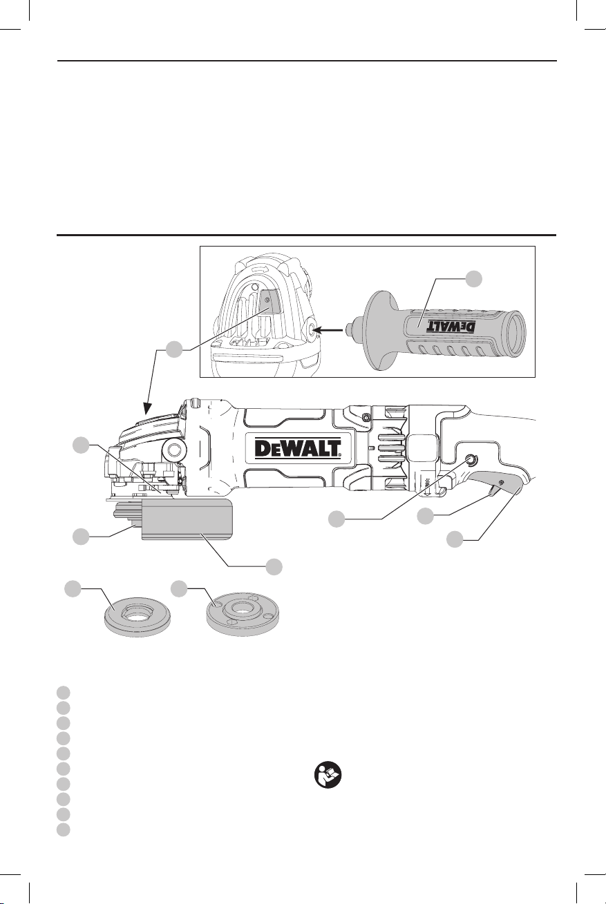
Fig. A
5
2
7
1
43
1
Spindle
2
Spindle lock button
3
Unthreaded backing flange
4
Threaded locking flange
5
Side handle
6
Guard
7
Guard release lever
8
Trigger switch
9
Trigger lock off
10
Lock-on button (DWE43066, DWE43113, DWE43115,
DWE43116)
10
6
WARNING! Read all safety warnings and all
instructions. Failure to follow the warnings and
instructions may result in electric shock, fire and/or
seriousinjury.
WARNING: To reduce the risk of injury, read the
instructionmanual.
If you have any questions or comments about this or
any
1-800-4-
tool, call us toll free at:
9
8
(1-800-433-9258).
1
Page 4

ENGLISH
GENERAL POWER TOOL SAFETY WARNINGS
WARNING! Read all safety warnings and all
instructions. Failure to follow the warnings and
instructions may result in electric shock, fire and/or
seriousinjury.
SAVE ALL WARNINGS AND
INSTRUCTIONS FOR FUTURE
REFERENCE
The term “power tool” in the warnings refers to your mainsoperated (corded) power tool or battery-operated (cordless)
powertool.
1) Work Area Safety
a ) Keep work area clean and well lit. Cluttered or dark
areas inviteaccidents.
b ) Do not operate power tools in explosive
atmospheres, such as in the presence of
flammable liquids, gases or dust. Power tools
create sparks which may ignite the dust orfumes.
c ) Keep children and bystanders away while
operating a power tool. Distractions can cause you
to losecontrol.
2) Electrical Safety
a ) Power tool plugs must match the outlet. Never
modify the plug in any way. Do not use any
adapter plugs with earthed (grounded) power
tools. Unmodified plugs and matching outlets will
reduce risk of electricshock.
b ) Avoid body contact with earthed or grounded
surfaces such as pipes, radiators, ranges and
refrigerators. There is an increased risk of electric
shock if your body is earthed orgrounded.
c ) Do not expose power tools to rain or wet
conditions. Water entering a power tool will increase
the risk of electricshock.
d ) Do not abuse the cord. Never use the cord for
carrying, pulling or unplugging the power tool.
Keep cord away from heat, oil, sharp edges or
moving parts. Damaged or entangled cords increase
the risk of electricshock.
e ) When operating a power tool outdoors, use an
extension cord suitable for outdoor use. Use of
a cord suitable for outdoor use reduces the risk of
electricshock.
f ) If operating a power tool in a damp location
is unavoidable, use a ground fault circuit
interrupter (GFCI) protected supply. Use of a GFCI
reduces the risk of electricshock.
3) Personal Safety
a ) Stay alert, watch what you are doing and use
common sense when operating a power tool. Do
not use a power tool while you are tired or under
the influence of drugs, alcohol or medication. A
moment of inattention while operating power tools
may result in serious personalinjury.
b ) Use personal protective equipment. Always wear
eye protection. Protective equipment such as dust
mask, non-skid safety shoes, hard hat, or hearing
protection used for appropriate conditions will reduce
personalinjuries.
c ) Prevent unintentional starting. Ensure the
switch is in the off position before connecting to
power source and/or battery pack, picking up or
carrying the tool. Carrying power tools with your
finger on the switch or energizing power tools that
have the switch on invitesaccidents.
d ) Remove any adjusting key or wrench before
turning the power tool on. A wrench or a key left
attached to a rotating part of the power tool may
result in personalinjury.
e ) Do not overreach. Keep proper footing and
balance at all times. This enables better control of
the power tool in unexpectedsituations.
f ) Dress properly. Do not wear loose clothing or
jewelry. Keep your hair, clothing and gloves
away from moving parts. Loose clothes, jewelry or
long hair can be caught in movingparts.
g ) If devices are provided for the connection of dust
extraction and collection facilities, ensure these
are connected and properly used. Use of dust
collection can reduce dust-relatedhazards.
4) Power Tool Use and Care
a ) Do not force the power tool. Use the correct
power tool for your application. The correct power
tool will do the job better and safer at the rate for
which it wasdesigned.
b ) Do not use the power tool if the switch does not
turn it on and off. Any power tool that cannot be
controlled with the switch is dangerous and must
berepaired.
c ) Disconnect the plug from the power source and/
or the battery pack from the power tool before
making any adjustments, changing accessories,
or storing power tools. Such preventive safety
measures reduce the risk of starting the power
toolaccidentally.
d ) Store idle power tools out of the reach of children
and do not allow persons unfamiliar with the
power tool or these instructions to operate the
power tool. Power tools are dangerous in the hands
of untrainedusers.
e ) Maintain power tools. Check for misalignment or
binding of moving parts, breakage of parts and
any other condition that may affect the power
tool’s operation. If damaged, have the power
tool repaired before use. Many accidents are
caused by poorly maintained powertools.
f ) Keep cutting tools sharp and clean. Properly
maintained cutting tools with sharp cutting edges are
less likely to bind and are easier tocontrol.
g ) Use the power tool, accessories and tool bits, etc.
in accordance with these instructions, taking
2
Page 5

into account the working conditions and the
work to be performed. Use of the power tool for
operations different from those intended could result
in a hazardoussituation.
5) Service
a ) Have your power tool serviced by a qualified
repair person using only identical replacement
parts. This will ensure that the safety of the power
tool ismaintained.
SAFETY INSTRUCTIONS FOR ALL
OPERATIONS
Safety Warnings Common for Grinding,
Sanding, Wire Brushing, Polishing or
Abrasive, Cutting-Off Operations
a ) This power tool is intended to function as a
grinder, sander, wire brush, polisher or cut-off
tool. Read all safety warnings, instructions,
illustrations and specifications provided with
this power tool. Failure to follow all instructions
listed below may result in electric shock, fire and/or
seriousinjury.
b ) Do not use accessories which are not specifically
designed and recommended by the tool
manufacturer. Just because the accessory can
be attached to your power tool, it does not assure
safeoperation.
c ) The rated speed of the accessory must be at least
equal to the maximum speed marked on the
power tool. Accessories running faster than their
rated speed can break and flyapart.
d ) The outside diameter and the thickness of your
accessory must be within the capacity rating of
your power tool. Incorrectly sized accessories cannot
be adequately guarded orcontrolled.
e ) Threaded mounting of accessories must match
the grinder spindle thread. For accessories
mounted by flanges, the arbor hole of the
accessory must fit the locating diameter of the
flange. Accessories that do not match the mounting
hardware of the power tool will run out of balance,
vibrate excessively and may cause loss ofcontrol.
f ) Do not use a damaged accessory. Before each
use inspect the accessory such as abrasive
wheels for chips and cracks, backing pad for
cracks, tear or excess wear, wire brush for loose
or cracked wires. If power tool or accessory
is dropped, inspect for damage or install an
undamaged accessory. After inspecting and
installing an accessory, position yourself and
bystanders away from the plane of the rotating
accessory and run the power tool at maximum
no-load speed for one minute. Damaged
accessories will normally break apart during this
testtime.
ENGLISH
g ) Wear personal protective equipment. Depending
on application, use face shield, safety goggles or
safety glasses. As appropriate, wear dust mask,
hearing protectors, gloves and workshop apron
capable of stopping small abrasive or workpiece
fragments. The eye protection must be capable
of stopping flying debris generated by various
operations. The dust mask or respirator must
be capable of filtrating particles generated by
your operation. Prolonged exposure to high intensity
noise may cause hearingloss.
h ) Keep bystanders a safe distance away from work
area. Anyone entering the work area must wear
personal protective equipment. Fragments of
workpiece or of a broken accessory may fly away and
cause injury beyond immediate area ofoperation.
i ) Hold the power tool by insulated gripping
surfaces only, when performing an operation
where the cutting accessory may contact hidden
wiring or its own cord. Cutting accessory contacting
a “live” wire may make exposed metal parts of the
power tool “live” and could give the operator an
electricshock.
j ) Position the cord clear of the spinning accessory.
If you lose control, the cord may be cut or snagged
and your hand or arm may be pulled into the
spinningaccessory.
k ) Never lay the power tool down until the
accessory has come to a complete stop. The
spinning accessory may grab the surface and pull the
power tool out of yourcontrol.
l ) Do not run the power tool while carrying it at
your side. Accidental contact with the spinning
accessory could snag your clothing, pulling the
accessory into yourbody.
m ) Regularly clean the power tool’s air vents. The
motor’s fan will draw the dust inside the housing and
excessive accumulation of powdered metal may cause
electricalhazards.
n ) Do not operate the power tool near flammable
materials. Sparks could ignite thesematerials.
o ) Do not use accessories that require liquid
coolants. Using water or other liquid coolants may
result in electrocution orshock.
p ) Do not use Type 11 (flaring cup) wheels on this
tool. Using inappropriate accessories can result
ininjury.
q ) Always use side handle. Tighten the handle
securely. The side handle should always be used to
maintain control of the tool at alltimes.
r ) When starting the tool with a new or
replacement wheel, or a new or replacement
wire brush installed, hold the tool in a well
protected area and let it run for one minute. If
the wheel has an undetected crack or flaw, it
should burst in less than one minute. If the wire
brush has loose wires, they will be detected.
3
Page 6

ENGLISH
Never start the tool with a person in line with the
wheel. This includes theoperator.
s ) Use of accessories not specified in this manual
is not recommended and may be hazardous.
Use of power boosters that would cause the tool
to be driven at speeds greater than its rated speed
constitutesmisuse.
t ) Use clamps or another practical way to secure
and support the workpiece to a stable platform.
Holding the work by hand or against your body leaves
it unstable and may lead to loss ofcontrol.
u ) Avoid bouncing the wheel or giving it rough
treatment. If this occurs, stop the tool and inspect the
wheel for cracks orflaws.
v ) Always handle and store wheels in a carefulmanner.
w ) Do not operate this tool for long periods of time.
Vibration caused by the operating action of this
tool may cause permanent injury to fingers,
hands, and arms. Use gloves to provide extra
cushion, take frequent rest periods, and limit daily
time ofuse.
x ) Air vents often cover moving parts and should be
avoided. Loose clothes, jewelry or long hair can be
caught in movingparts.
Causes and Operator Prevention
of Kickback
Kickback is a sudden reaction to a pinched or snagged
rotating wheel, backing pad, brush or any other accessory.
Pinching or snagging causes rapid stalling of the rotating
accessory which in turn causes the uncontrolled power tool to
be forced in the direction opposite of the accessory’s rotation
at the point of thebinding.
For example, if an abrasive wheel is snagged or pinched by
the workpiece, the edge of the wheel that is entering into the
pinch point can dig into the surface of the material causing
the wheel to climb out or kick out. The wheel may either jump
toward or away from the operator, depending on direction
of the wheel’s movement at the point of pinching. Abrasive
wheels may also break under theseconditions.
Kickback is the result of tool misuse and/or incorrect operating
procedures or conditions and can be avoided by taking proper
precautions as given below:
a ) Maintain a firm grip on the power tool and
position your body and arm to allow you to resist
kickback forces. Always use auxiliary handle, if
provided, for maximum control over kickback or
torque reaction during start up. The operator can
control torque reaction or kickback forces, if proper
precautions aretaken.
b ) Never place your hand near the rotating
accessory. Accessory may kickback over yourhand.
c ) Do not position your body in the area where
power tool will move if kickback occurs. Kickback
will propel the tool in direction opposite to the wheel’s
movement at the point ofsnagging.
d ) Use special care when working corners, sharp
edges etc. Avoid bouncing and snagging the
accessory. Corners, sharp edges or bouncing have
a tendency to snag the rotating accessory and cause
loss of control orkickback.
e ) Do not attach a saw chain woodcarving blade
or toothed saw blade. Such blades create frequent
kickback and loss ofcontrol.
Safety Warnings Specific for Grinding and
Abrasive Cutting-Off Operations
a ) Use only wheel types that are recommended for
your power tool and the specific guard designed
for the selected wheel. Wheels for which the power
tool was not designed cannot be adequately guarded
and areunsafe.
b ) The grinding surface of center depressed
wheels must be mounted below the plane of
the guard lip. An improperly mounted wheel that
projects through the plane of the guard lip cannot be
adequatelyprotected.
c ) The guard must be securely attached to the
power tool and positioned for maximum safety,
so the least amount of wheel is exposed towards
the operator. The guard helps to protect the operator
from broken wheel fragments, accidental contact with
wheel and sparks that could igniteclothing.
d ) Wheels must be used only for recommended
applications. For example: do not grind with the
side of cut-off wheel. Abrasive cut-off wheels are
intended for peripheral grinding, side forces applied to
these wheels may cause them toshatter.
e ) Always use undamaged wheel flanges that
are of correct size and shape for your selected
wheel. Proper wheel flanges support the wheel
thus reducing the possibility of wheel breakage.
Flanges for cut-off wheels may be different from
grinding wheelflanges.
f ) Do not use worn down wheels from larger power
tools. Wheel intended for larger power tool is not
suitable for the higher speed of a smaller tool and
mayburst.
Additional Safety Warnings Specific for
Abrasive Cutting-Off Operations
a ) Do not “jam” the cut-off wheel or apply excessive
pressure. Do not attempt to make an excessive
depth of cut. Overstressing the wheel increases the
loading and susceptibility to twisting or binding of
the wheel in the cut and the possibility of kickback or
wheelbreakage.
b ) Do not position your body in line with and
behind the rotating wheel. When the wheel, at the
point of operation, is moving away from your body,
the possible kickback may propel the spinning wheel
and the power tool directly atyou.
4
Page 7

c ) When wheel is binding or when interrupting
a cut for any reason, switch off the power tool
and hold the power tool motionless until the
wheel comes to a complete stop. Never attempt
to remove the cut-off wheel from the cut while
the wheel is in motion otherwise kickback may
occur. Investigate and take corrective action to
eliminate the cause of wheelbinding.
d ) Do not restart the cutting operation in the
workpiece. Let the wheel reach full speed and
carefully reenter the cut. The wheel may bind,
walk up or kickback if the power tool is restarted in
theworkpiece.
e ) Support panels or any oversized workpiece
to minimize the risk of wheel pinching and
kickback. Large workpieces tend to sag under
their own weight. Supports must be placed under
the workpiece near the line of cut and near the edge of
the workpiece on both sides of thewheel.
f ) Use extra caution when making a “pocket
cut” into existing walls or other blind areas.
The protruding wheel may cut gas or water pipes,
electrical wiring or objects that can causekickback.
Safety Warnings Specific for Sanding
Operations
a ) Do not use excessively oversized sanding disc
paper. Follow manufacturers recommendations,
when selecting sanding paper. Larger sanding
paper extending beyond the sanding pad presents a
laceration hazard and may cause snagging, tearing of
the disc orkickback.
Safety Warnings Specific for Polishing
Operations
a ) Do not allow any loose portion of the polishing
bonnet or its attachment strings to spin freely.
Tuck away or trim any loose attachment strings.
Loose and spinning attachment strings can entangle
your fingers or snag on theworkpiece.
Safety Warnings Specific for Wire
Brushing Operations
a ) Be aware that wire bristles are thrown by the
brush even during ordinary operation. Do not
overstress the wires by applying excessive load
to the brush. The wire bristles can easily penetrate
light clothing and/orskin.
b ) If the use of a guard is recommended for wire
brushing, do not allow any interference of the
wire wheel or brush with the guard. Wire wheel
or brush may expand in diameter due to work and
centrifugalforces.
c ) Safety goggles or safety glasses with side shields
and a full face shield compliant with ANSI Z87.1
MUST be worn by the operator and others that
are within 50' (15.2 m) of the use of thisproduct.
ENGLISH
Additional Safety Information
WARNING: ALWAYS use safety glasses. Everyday
eyeglasses are NOT safety glasses. Also use face or
dust mask if cutting operation is dusty. ALWAYS WEAR
CERTIFIED SAFETYEQUIPMENT:
• ANSI Z87.1 eye protection (CAN/CSA Z94.3),
• ANSI S12.6 (S3.19) hearing protection,
• NIOSH/OSHA/MSHA respiratoryprotection.
WARNING: Some dust created by power sanding,
sawing, grinding, drilling, and other construction
activities contains chemicals known to the State
of California to cause cancer, birth defects or
other reproductive harm. Some examples of these
chemicalsare:
• lead from lead-based paints,
• crystalline silica from bricks and cement and other
masonry products, and
• arsenic and chromium from chemicallytreatedlumber.
Your risk from these exposures varies, depending on how
often you do this type of work. To reduce your exposure to
these chemicals: work in a well ventilated area, and work with
approved safety equipment, such as those dust masks that are
specially designed to filter out microscopicparticles.
• Avoid prolonged contact with dust from power
sanding, sawing, grinding, drilling, and other
construction activities. Wear protective clothing and
wash exposed areas with soap and water. Allowing
dust to get into your mouth, eyes, or lay on the skin may
promote absorption of harmfulchemicals.
WARNING: Use of this tool can generate and/
or disperse dust, which may cause serious and
permanent respiratory or other injury. Always use
NIOSH/OSHA approved respiratory protection
appropriate for the dust exposure. Direct particles
away from face andbody.
WARNING: Always wear proper personal hearing
protection that conforms to ANSI S12.6 (S3.19)
during use. Under some conditions and duration
of use, noise from this product may contribute to
hearingloss.
CAUTION: When not in use, place tool on its side
on a stable surface where it will not cause a
tripping or falling hazard. Some tools with large
battery packs will stand upright on the battery pack
but may be easily knockedover.
• Air vents often cover moving parts and should be
avoided. Loose clothes, jewelry or long hair can be
caught in movingparts.
• An extension cord must have adequate wire size
(AWG or American Wire Gauge) for safety. The smaller
the gauge number of the wire, the greater the capacity
of the cable, that is, 16 gauge has more capacity than 18
gauge. An undersized cord will cause a drop in line voltage
resulting in loss of power and overheating. When using
more than one extension to make up the total length,
be sure each individual extension contains at least the
5
Page 8

ENGLISH
DeWALT
minimum wire size. The following table shows the correct
size to use depending on cord length and nameplate
ampere rating. If in doubt, use the next heavier gauge. The
lower the gauge number, the heavier thecord.
Minimum Gauge for Cord Sets
Volts
120 V 25 (7.6) 50 (15.2) 100 (30.5) 150 (45.7)
240 V 50 (15.2) 100 (30.5) 200 (61.0) 300 (91.4)
Ampere Rating
More
Not
Than
More
Than
0 6 18 16 16 14
6 10 18 16 14 12
10 12 16 16 14 12
12 16 14 12 Not Recommended
The label on your tool may include the following symbols. The
symbols and their definitions are asfollows:
V ......................... volts
Hz ....................... hertz
min ..................... minutes
or DC ......direct current
...................... Class I Construction
…/min .............. per minute
BPM .................... beats per minute
IPM ..................... impacts per minute
RPM .................... revolutions per
sfpm ................... surface feet per
SPM .................... strokes per minute
A ......................... amperes
W ........................ watts
or AC ........... alternating current
Total Length of Cord in Feet
American Wire Gauge
(grounded)
minute
minute
no ....................... no load speed
n ......................... rated speed
(meters)
or AC/DC .... alternating or
direct current
...................... Class II
Construction
(double insulated)
...................... earthing terminal
..................... safety alert symbol
..................... visible radiation
..................... wear respiratory
protection
..................... wear eye
protection
..................... wear hearing
protection
..................... read all
documentation
Lanyard Connection (Fig. B)
DWE43066N, DWE43115N
Safety Warnings Specific for Use At Height
WARNING: If the tool is dropped for any reason the
lanyard connection must be inspected and properly
serviced prior to re-use. The lanyard connection is
designed to stretch to absorb the shock of a drop.
Any permanent stretch to the connection exposing
the red marked internal coils indicates it has been
compromised and must be serviced prior to reuse.
• Always keep the tool and accessories tethered when
working "at height". (Maximum lanyard length:
6.5 ft [2m])
• Use only with lanyards appropriate for this tool type and
rated for at least 6.0 lbs (2.72 Kg).
• Crush, cut or entanglement hazard. Do not use near
moving parts, mechanisms or runningmachinery.
• Do not anchor the tool lanyard to anything on your body.
Anchor to a rigid structure that can withstand the forces
of a droppedtool.
• Make sure the lanyard is properly secure at each end prior
touse.
• Inspect tool and lanyard before each use for damage and
proper function (including fabric and stitching). Do not
use if damaged or not functioningproperly.
• Do not alter the lanyard connection or use in a manner
other than as instructed in thismanual.
• Only attach tool to a lanyard with a locking carabiner. Do
not attach by looping or knotting the lanyard. Do not use
rope orcord.
• Electrical shock hazard. Be sure power is off when working
in high voltage areas. Some lanyards areconductive.
• Dropped tools will swing on the lanyard, which could
cause injury or loss ofbalance.
• Do not carry the tool by attachment device or thelanyard.
• Do not attach more than one tool to eachlanyard.
• Only use appropriate
NEVER modify tools to create attachmentpoints.
• Only transfer the tool between hands while properly
balanced in a stableorientation.
• Do not attach lanyards to tool in a way that keeps guards,
switches or lock-offs from operatingproperly.
• Avoid getting tangled in thelanyard.
• Keep lanyard away from the cutting area of thetool.
• Do not use lanyards or attachment devices to get
additional leverage from thetool.
• Do not use for personal fallprotection.
• Falling object hazard! Only change accesories and
attachments where a dropped object won't cause a
hazard below you. Consult your AHJ or site supervisor for
procedures for working atheight.
• Use multi-action and screw gate type carabineers. Do not
use single action spring clip carabineers.
The lanyard connection
competent personnel, who are trained and knowledgeable
regarding working with tools in and around machinery and
"at height".A lanyard connection may be added to certain
models by an authorized service center.
Fig. B
brand attachment point.
21
is intended for use by
21
SAVE THESE INSTRUCTIONS FOR
FUTURE USE
Motor
Be sure your power supply agrees with the nameplate
marking. Voltage decrease of more than 10% will cause loss
6
Page 9

of power and overheating.
DeWALT
if this tool does not operate, check power supply.
tools are factory tested;
COMPONENTS (FIG. A)
WARNING: Never modify the power tool or any part
of it. Damage or personal injury couldresult.
Refer to Figure A at the beginning of this manual for a
complete list ofcomponents.
Intended Use
Your heavy-duty small angle grinder has been designed
for professional grinding, sanding, wire brush, and cut-off
applications at various work sites (i.e., construction sites).
DO NOT use under wet conditions or in presence of
flammable liquids orgases.
Your heavy-duty small angle grinders is a professional
power tool. DO NOT let children come into contact with the
tool. Supervision is required when inexperienced operators
use thistool.
Features
(DWE43113, DWE43116 excluded)
E-switch Protection™
The ON/OFF trigger switch has a no-volt release function.
In the event of a power outage or other unexpected shut
down, the trigger switch will need to be cycled (turned on
and off) to restarttool.
E-Clutch™
This unit is equipped with an E-Clutch™ (Electronic Clutch),
which in the event of a high-load or wheel pinch, the
unit will be shut off to reduce the reaction torque to the
user. The switch needs to be cycled (turned on and off) to
restarttool.
Power-OFF™ Overload Protection
The power supply to the motor will be reduced in case
of motor overload. With continued motor overload, the
tool will shut off. The switch needs to be cycled (turned
on and off) to restart tool. The tool will power off each
time the current load reaches the overload current value
(motor burn-up point). If continued overload shutdowns
occur, apply less force/weight on the tool until the tool will
function without the overloadengaging.
Electronic Soft Start
This feature limits the initial start up momentum, allowing
the speed to build up gradually over a 1 secondperiod.
ASSEMBLY AND ADJUSTMENTS
WARNING: To reduce the risk of serious personal
injury, turn unit off and disconnect it from
power source before making any adjustments or
removing/installing attachments or accessories.
An accidental start-up can causeinjury.
ENGLISH
Screw the side handle
either side of the gear case. The side handle should always
be used to maintain control of the tool at alltimes.
5
tightly into one of the holes on
Guards
CAUTION: Guards must be used with all grinding
wheels, cutting wheels, sanding flap discs,
wire brushes, and wire wheels. The tool may
be used without a guard only when sanding with
conventional sanding discs. Refer to Figure A to see
guards provided with the unit. Some applications may
require purchasing the correct guard from your local
dealer or authorized service center.
NOTE: Edge grinding and cutting can be performed with
Type 27 wheels designed and specified for this purpose;
6.35 mm thick wheels are designed for surface grinding
while thinner Type 27 wheels need to be examined for
the manufacturer's label to see if they can be used for
surface grinding or only edge grinding/cutting. A Type 1
guard must be used for any wheel where surface grinding
is forbidden. Cutting can also be performed by using a
Type41 wheel and a Type 1guard.
NOTE: See the Accessories Chart to select the proper guard
/ accessory combination.
Adjusting and Mounting
Guard (Fig. C, D)
CAUTION: Turn unit off and unplug the tool before
making any adjustments or removing or installing
attachments or accessories.
CAUTION: BEFORE operating the tool, identify which
guard adjustment option your tool is set to.
Adjustment Options
For guard adjustment, the guard release lever
one of the alignment holes
ratcheting feature. Your grinder offers two options for this
adjustment.
• One-touch
is slanted and will ride over to the next alignment
hole when guard is rotated in a clockwise direction
(spindle facing user) but self-locks in the counterclockwisedirection.
• Two-touch
straight and squared off. It will NOT ride over to the next
alignment hole unless guard release lever is pressed and
held while simultaneously rotating the guard in either
a clockwise or counter-clockwise direction (spindle
facinguser).
TM
TM
13
on the guard collar using a
: In this position the engaging face
: In this position the engaging face is
7
engages
Attaching Side Handle (Fig. A)
WARNING: Before using the tool, check that the
handle is tightenedsecurely.
7
Page 10

ENGLISH
Fig. C
11
7
12
desired working position. Press and hold the guard
release lever
clockwise direction.
Two-touch
lever
clockwise into the desired working position.
NOTE: The guard body should be positioned between
the spindle and the operator to provide maximum
operator protection.
The guard release lever should snap into one of the
alignment holes
that the guard is secure.
5. To remove the guard, follow steps 1–3 of these
instructions in reverse.
Fig. D
7
to rotate the guard in the counter-
TM
: Press and hold the guard release
7
. Rotate the guard clockwise or counter-
13
on the guard collar. This ensures
13
TM
One-Touch
Setting Guard Adjustment Options
To adjust the guard release lever
adjustmentoption:
1. Remove screw
2. Remove the guard release lever taking note of the
spring position. Choose the end of the lever for the
desired adjustment option. One-touch will use the
slanted end of the lever
holes
squaredend to engage the alignment holes
guard collar.
3. Replace the lever, positioning the chosen end under the
spring
thespring.
4. Replace screw and torque to 2.0-3.0N-m. Ensure proper
installation with spring return function by depressing
guard release lever
Mounting Guard (Fig. D)
CAUTION: Prior to mounting guard, ensure the screw,
lever, and spring are fitted correctly before mounting
theguard.
1. With the spindle facing the operator, press and hold the
guard release lever
2. Align the lugs
the gearcase cover.
3. Push the guard down until the guard lugs engage
and rotate them in the groove on the gear case cover.
Release the guard release lever.
4. To position the guard:
One-touch
8
11
using a T20 bit.
13
on the guard collar. Two-touch will use the
12
. Ensure the lever is in proper contact with
14
on the guard with the slots
TM
: Rotate the guard clockwise into the
7
7
to engage the alignment
7
.
7
.
Two-Touch
for desired
TM
13
on the
15
on
15
14
7
Flanges and Wheels
CAUTION: Turn unit off and unplug the tool before
making any adjustments or removing or installing
attachments or accessories.
Mounting Non-Hubbed Wheels (Fig. E, F)
WARNING: Failure to properly seat the flanges and/or
wheel could result in serious injury (or damage to the
tool or wheel).
CAUTION: Included flanges must be used with
depressed center Type 27/42 grinding wheels and
Type1/41 cutting wheels. See the Accessories Chart
for more information.
WARNING: A closed, two-sided cutting wheel guard
is required when using abrasive cutting wheels or
diamond coated cutting wheels.
WARNING: Use of a damaged flange or guard or fail-
ure to use proper flange and guard can re sult in injury
due to wheel breakage and wheel contact. See the
Accessories Chart for more information.
1. Place the tool on a table, guard up.
2. Install the unthreaded backing flange
with the raised center (pilot) facing the wheel.
3
on spindle
1
Page 11
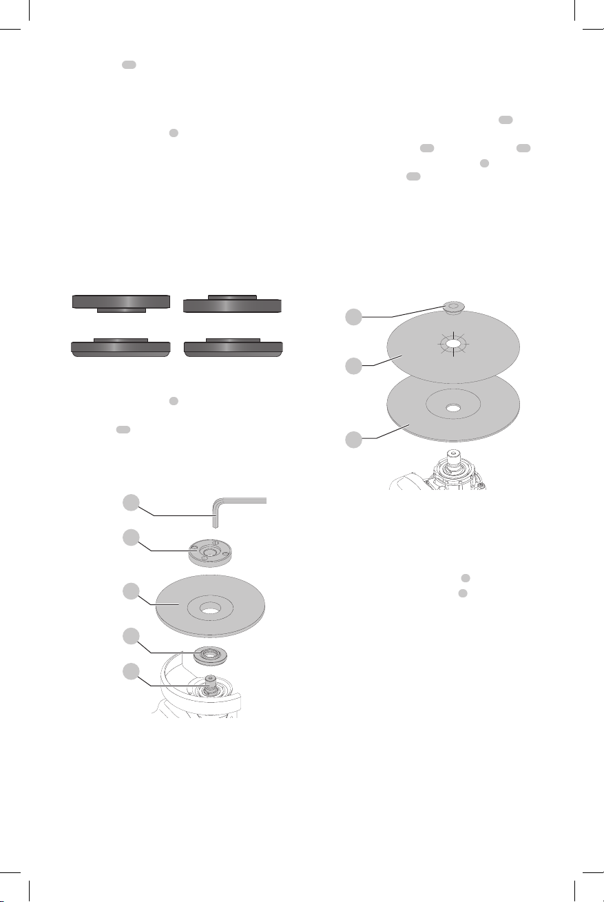
3. Place wheel
centering the wheel on the raised center (pilot) of the
backingflange.
4. While depressing the spindle lock button and with the
hex depressions facing away from the wheel, thread the
threaded locking flange
engage the two slots in the spindle.
NOTE: If the wheel you are installing is more than 1/8"
(3.17mm) thick, place the threaded locking flange on
the spindle so that the raised section (pilot) fits into the
center of the wheel. If the wheel you are installing is
1/8" (3.17mm) thick or less, place the threaded locking
flange on the spindle so that the raised section (pilot) is
not against thewheel.
Fig. E
17
against the backing flange,
Over 1/8" (3.17mm)
wheels
Locking flange
4
on spindle so that the lugs
1/8" Or less (3.17mm)
wheels
Locking flange
ENGLISH
WARNING: Proper guard must be reinstalled for
grinding wheel, cutting wheel, sanding flap disc,
wire brush or wire wheel applications after sanding
applications are complete.
1. Place or appropriately thread backing pad
thespindle.
2. Place the sanding disc
3. While depressing spindle lock button
sanding clamp nut
hub on the clamp nut into the center of san ding disc
and backingpad.
4. Tighten the clamp nut by hand. Then depress the
spindle lock button while turning the sanding disc until
the sanding disc and clamp nut are snug.
5. To remove the wheel, grasp and turn the backing pad
and sanding pad while depressing the spindle
lock button.
Fig. G
19
18
on the backing pad
19
on spindle, piloting the raised
20
2
, thread the
on
20
.
Backing Flange
5. While depressing the spindle lock button, tighten the
threaded locking flange
a. Tighten the threaded locking flange using a
b. Tighten a keyless locking flange by hand. (Only use a
6. To remove the wheel, depress the spindle lock button
and loosen the threaded locking flange.
Mounting Sanding Backing Pads (Fig. G)
NOTE: Use of a guard with sanding discs that use backing
pads, often called fiber resin discs, is not required. Since a
guard is not required for these accessories, the guard may or
may not fit correctly if used.
16
wrench
keyless locking flange if it is in perfect condition.)
Fig. F
WARNING: Failure to properly seat the clamp nut
and/or pad could result in serious injury (or damage
to the tool or wheel).
.
16
4
17
3
1
4
:
Backing Flange
18
20
Mounting and Removing Hubbed
Wheels (Fig. A)
Hubbed wheels install directly on the spindle. Thread of
accessory must match thread of spindle.
1. Remove backing flange by pulling away from tool.
2. Thread the wheel on the spindle
3. Depress the spindle lock button
tighten the hub of the wheel.
4. Reverse the above procedure to remove the wheel.
NOTICE: Failure to properly seat the wheel before
turning the tool on may result in damage to the tool
or the wheel.
Mounting Wire Cup Brushes and
Wire Wheels (Fig. A)
WARNING: Failure to properly seat the brush/wheel
could result in serious injury (or damage to the tool
or wheel).
CAUTION: To reduce the risk of personal injury,
wear work gloves when handling wire brushes
and wheels. They can become sharp.
CAUTION: To reduce the risk of damage to the
tool, wheel or brush must not touch guard when
mounted or while in use. Undetectable damage
1
by hand.
2
and use a wrench to
9
Page 12

ENGLISH
could occur to the accessory, causing wires to
fragment from accessory wheel or cup.
Wire cup brushes or wire wheels install directly on the
threaded spindle without the use of flanges. Use only wire
brushes or wheels provided with a threaded hub. These
accessories are available at extra cost from your local dealer
or authorised service center.
1. Place the tool on a table, guard up.
2. Thread the wheel on the spindle by hand.
3. Depress spindle lock button
hub of the wire wheel or brush to tighten the wheel.
4. To remove the wheel, reverse the above procedure.
NOTICE: To reduce the risk of damage to the tool,
properly seat the wheel hub before turning the tool on.
2
and use a wrench on the
Prior to Operation
• Install the guard and appropriate disc or wheel. Do not
use excessively worn discs orwheels.
• Be sure the backing and threaded locking flange are
mounted correctly. Follow the instructions given in the
Grinding and Cutting AccessoryChart.
• Make sure the disc or wheel rotates in the direction of
the arrows on the accessory and thetool.
• Do not use a damaged accessory. Before each use
inspect the accessory such as abrasive wheels for chips
and cracks, backing pad for cracks, tear or excess wear,
wire brush for loose or cracked wires. If power tool or
accessory is dropped, inspect for damage or install an
undamaged accessory. After inspecting and installing
an accessory, position yourself and bystanders away
from the plane of the rotating accessory and run the
power tool at maximum no-load speed for one minute.
Damaged accessories will normally break apart during
this testtime.
OPERATION
WARNING: To reduce the risk of serious personal
injury, turn unit off and disconnect it from
power source before making any adjustments or
removing/installing attachments or accessories.
An accidental start-up can causeinjury.
Proper Hand Position (Fig. H)
WARNING: To reduce the risk of serious personal
injury, ALWAYS use proper hand position as shown.
WARNING: To reduce the risk of serious personal
injury, ALWAYS hold securely in anticipation of a
sudden reaction.
Proper hand position requires one hand on the side
5
handle
, with the other hand on the body of the tool, as
shown in FigureH.
Fig. H
Trigger Switch and Lock-off Lever (Fig. I)
WARNING: Before using the tool, check that the side
handle is tightened securely.
CAUTION: Hold the side handle and body of the tool
firmly to maintain control of the tool at start up and
during use and until the wheel or accessory stops
rotating. Make sure the wheel has come to a complete
stop be fore laying the tooldown.
1. To turn the tool on, push the lock-off lever
the back of the tool, then depress the trigger switch
The tool will run while the switch is depressed.
2. Turn the tool off by releasing the releasing switch.
WARNING: Allow the tool to reach full speed before
touching tool to the work surface. Lift the tool from
the work surface before turning the tool off.
Fig. I
10
Lock-On Button
DWE43066, DWE43113, DWE43115, DWE43116
The lock-on button
extended use applications. To lock the tool on, depress
the lock-on button while the tool is running. The tool will
continue to run after the switch is released. To unlock and
turn off the tool, depress and release the switch.
NOTE: A grinder should never be locked ON by any
othermeans.
10
offers increased comfort in
9
toward
8
9
Spindle Lock (Fig. A)
The spindle lock
rotating when installing or removing wheels. Operate the
spindle lock only when the tool is turned off, unplugged
from the power supply, and has come to a completestop.
2
is provided to prevent the spindle from
NOTICE: To reduce the risk of damage to the tool, do
not engage the spindle lock while the tool is operating.
Damage to the tool will result and attached accessory
may spin off possibly resulting ininjury.
5
8
.
10
Page 13

To engage the lock, depress the spindle lock button
and rotate the spindle until you are unable to rotate the
spindlefurther.
Surface Grinding, Sanding and Wire
Brushing (Fig. J)
CAUTION: Always use the correct guard per the
instructions in this manual.
WARNING: Metal dust build-up. Extensive use
of flap discs in metal applications can result in the
increased potential for electric shock. To reduce
this risk, insert an RCD before use and clean the
ventilation slots daily by blowing dry compressed air
into the ventilation slots inaccordance with the below
maintenanceinstructions.
To perform work on the surface of a workpiece:
1. Allow the tool to reach full speed before touching the
tool to the work surface.
2. Apply minimum pressure to the work surface, allowing
the tool to operate at high speed. Material removal rate
is greatest when the tool operates at high speed.
Fig. J
Angle
3. Maintain an appropriate angle between the tool
and work surface. Refer to the chart according to
particularfunction.
Function Angle
Grinding 20˚-30˚
Sanding with Flap Disc 5˚-10˚
Sanding with Backing Pad 5˚-15˚
Wire Brushing 5˚-10˚
4. Maintain contact between the edge of the wheel and
the work surface.
- If grinding, sanding with flap discs or wire brushing
move the tool continuously in a forward and
back motion to avoid creating gouges in the
worksurface.
- If sanding with a backing pad, move the tool
constantly in a straight line to prevent burning and
swirling of worksurface.
NOTE: Allowing the tool to rest on the work surface without
moving will damage the work piece.
5. Remove the tool from work surface before turning tool
off. Allow the tool to stop rotating before laying it down.
CAUTION: Use extra care when working over an edge,
as a sudden sharp movement of grinder
may be experienced.
ENGLISH
Precautions To Take When Working on
a Painted Workpiece
1. Sanding or wire brushing of lead based paint is NOT
RECOMMENDED due to the difficulty of controlling
the contaminated dust. The greatest danger of lead
poisoning is to children and pregnant women.
2. Since it is difficult to identify whether or not a paint
contains lead without a chemical analysis, we
recommend the following precautions when sanding
any paint:
Personal Safety
1. No children or pregnant women should enter the work
area where the paint sanding or wire brushing is being
done until all clean up is completed.
2. A dust mask or respirator should be worn by all persons
entering the work area. The filter should be replaced
daily or whenever the wearer has difficulty breathing.
NOTE: Only those dust masks suitable for working with
lead paint dust and fumes should be used. Ordinary
painting masks do not offer this protection. See your
local hardware dealer for the proper N.I.O.S.H.
approved mask.
3. NO EATING, DRINKING or SMOKING should be done in
the work area to prevent ingesting contaminated paint
particles. Workers should wash and clean up BEFORE
eating, drinking or smoking. Articles of food, drink, or
smoking should not be left in the work area where dust
would settle on them.
Environmental Safety
1. Paint should be removed in such a manner as to
minimize the amount of dust generated.
2. Areas where paint removal is occurring should be sealed
with plastic sheeting of 4 mils thickness.
3. Sanding should be done in a manner to reduce tracking
of paint dust outside the work area.
Cleaning and Disposal
1. All surfaces in the work area should be vacuumed
and thoroughly cleaned daily for the duration of
the sanding project. Vacuum filter bags should be
changedfrequently.
2. Plastic drop cloths should be gathered up and disposed
of along with any dust chips or other removal debris.
They should be placed in sealed refuse receptacles and
disposed of through regular trash pick-up procedures.
During clean up, children and pregnant women should
be kept away from the immediate work area.
3. All toys, washable furniture and utensils used by
children should be washed thoroughly before being
used again.
Edge Grinding and Cutting (Fig. K)
WARNING: Do not use edge grinding/cutting wheels
for surface grinding applications because these wheels
are not designed for side pressures encountered with
surface grinding. Wheel breakage and injury
may result.
11
Page 14

ENGLISH
DeWALT
DeWALT
DeWALT
DeWALT
DeWALT
DeWALT
DeWALT
DeWALT
DeWALT
DeWALT
CAUTION: Wheels used for edge grinding and cutting
may break or kick back if they bend or twist while
the tool is being used. In all edge grinding/cutting
operations, the open side of the guard must be
positioned away from theoperator.
NOTICE: Edge grinding/cutting with a Type27 wheel
must be limited to shallow cutting and notching—
less than 13mm in depth when the wheel is new.
Reduce the depth of cutting/notching equal to the
reduction of the wheel radius as it wears down. Refer
to the Accessories Chart for more information. Edge
grinding/cutting with a Type 41 wheel requires usage
of a Type 1 guard.
1. Allow the tool to reach full speed before touching the
tool to the work surface.
2. Apply minimum pressure to the work surface, allowing
the tool to operate at high speed. Grinding/cutting rate
is greatest when the tool operates at high speed.
3. Position yourself so that the open-underside of the
wheel is facing away from you.
4. Once a cut is begun and a notch is established in
the workpiece, do not change the angle of the cut.
Changing the angle will cause the wheel to bend and
may cause wheel breakage. Edge grinding wheels
are not designed to withstand side pressures caused
bybending.
Fig. K
5. Remove the tool from the work surface before turning
the tool off. Allow the tool to stop rotating before laying
itdown.
MAINTENANCE
WARNING: To reduce the risk of serious personal
injury, turn unit off and disconnect it from
power source before making any adjustments or
removing/installing attachments or accessories.
An accidental start-up can causeinjury.
Cleaning
WARNING: Blow dirt and dust out of all air vents with
clean, dry air at least once a week. To minimize the risk
of eye injury, always wear ANSI Z87.1 approved eye
protection when performingthis.
WARNING: Never use solvents or other harsh
chemicals for cleaning the non-metallic parts of
the tool. These chemicals may weaken the plastic
materials used in these parts. Use a cloth dampened
only with water and mild soap. Never let any liquid
get inside the tool; never immerse any part of the tool
into aliquid.
Accessories
WARNING: Since accessories, other than those
offered by
product, use of such accessories with this tool could be
hazardous. To reduce the risk of injury, only
recommended accessories should be used with
thisproduct.
Recommended accessories for use with your tool
are available at extra cost from your local dealer or
authorized service center. If you need assistance in
locating any accessory, please contact
Tool Co., 701East Joppa Road, Towson, MD 21286, call
1-800-4www.dewalt.com.
, have not been tested with this
(1-800-433-9258) or visit our website:
Repairs
The charger and battery pack are notserviceable.
WARNING: To assure product SAFETY and
RELIABILITY, repairs, maintenance and adjustment
(including brush inspection and replacement) should
be performed by a
or a
identical replacementparts.
authorized service center. Always use
factory service center
Register Online
Thank you for your purchase. Register your product nowfor:
• WARRANTY SERVICE: Registering your product will
help you obtain more efficient warranty service in case
there is a problem with yourproduct.
• CONFIRMATION OF OWNERSHIP: In case of
an insurance loss, such as fire, flood or theft, your
registration of ownership will serve as your proof
ofpurchase.
• FOR YOUR SAFETY: Registering your product will
allow us to contact you in the unlikely event a safety
notification is required under the Federal Consumer
SafetyAct.
Register online at www.dewalt.com/register.
Three Year Limited Warranty
will repair, without charge, any defects due to
faulty materials or workmanship for three years from the
date of purchase. This warranty does not cover part failure
due to normal wear or tool abuse. For further detail of
warranty coverage and warranty repair information, visit
www.dewalt.com or call 1-800-4This warranty does not apply to accessories or damage
caused where repairs have been made or attempted by
others. This warranty gives you specific legal rights and
you may have other rights which vary in certain states
orprovinces.
In addition to the warranty,
byour:
will maintain the tool and replace worn parts
caused by normal use, for free, any time during the first year
afterpurchase.
1 YEAR FREE SERVICE
(1-800-433-9258).
tools are covered
Industrial
12
Page 15

90 DAY MONEY BACK GUARANTEE
DeWALT
DeWALT
If you are not completely satisfied with the performance of
your
can return it within 90 days from the date of purchase with
a receipt for a full refund – no questionsasked.
LATIN AMERICA: This warranty does not apply to products
sold in Latin America. For products sold in Latin America,
see country specific warranty information contained in
the packaging, call the local company or see website for
warrantyinformation.
FREE WARNING LABEL REPLACEMENT: If your warning
labels become illegible or are missing, call 1-800-4(1-800-433-9258) for a freereplacement.
Power Tool, Laser, or Nailer for any reason, you
ENGLISH
13
Page 16

ENGLISH
ACCESSORIES CHART
4.5" (115 mm) and 6" (150mm) Grinding Wheels
Wire Wheels
Type 27 guard
unthreaded backing flange
Type 27
depressed center wheel
threaded locking flange
4.5" (115 mm)and 6" (150mm) Cutting Wheels
Type 27 guard
Type 27 hubbed wheel
4.5" (115 mm) and 6" (150mm) Sanding Flap Discs
Type 27 guard
unthreaded backing flange
non-hubbed sanding flap disc
threaded locking flange
Type 27 guard
3 - 5" * (76.2 - 127 mm)
wire cup brush
Type 27 guard
hubbed sanding flap disc
Type 27 guard
4"-6" (100-150 mm) wire
wheel
Sanding Discs
rubber backing pad
sanding disc
sanding clamp nut
Type 1/41 guard*
unthreaded backing flange
Type 27/42 depressed
center wheel, cutting only
threaded locking flange
Type 1/41 guards are intended for use with Type 1/41 cutting wheels and Type 27 wheels marked for cutting only.
Grinding with wheels other than Type 27 and Type 29 require different accessory guards. Always use the smallest proper
guard possible that does not contact the accessory.
* NOTE: A Type 1/41 guard is available at extra cost from your local dealer or authorized service center.
* NOTE: A Type 1/41 guard is included with the DWE43066 and DWE43066N.
14
Type 1/41 guard*
unthreaded backing flange
Type 1/41 abrasive cutting
wheel
threaded locking flange
Type 1/41 guard*
unthreaded backing flange
diamond cutting wheel
threaded locking flange
Page 17

Définitions : symboles et termes d'alarmes sécurité
DeWALT
DeWALT
Ces guides d'utilisation utilisent les symboles et termes d'alarmes sécurité suivants pour vous prévenir de situations
dangereuses et de risques de dommages corporels ou matériels.
DANGER: indique une situation dangereuse imminente qui, si elle n’est pas évitée, entraînera la mort ou des
blessuresgraves.
AVERTISSEMENT: indique une situation potentiellement dangereuse qui, si elle n’est pas évitée, pourrait entraîner la
mort ou des blessuresgraves.
ATTENTION: indique une situation potentiellement dangereuse qui, si elle n’est pas évitée, pourrait entraîner des
blessures légères oumodérées.
(Si utilisé sans aucun terme) Indique un message propre à la sécurité.
AVIS : indique une pratique ne posant aucun risque de dommages corporels mais qui par contre, si rien n’est fait
pour l’éviter, pourrait poser des risques de dommages matériels.
Fig. A
5
2
FRANÇAIS
7
1
43
1
Broche
2
Bouton de verrouillage de la broche
3
Bride de soutien non fileté
4
Bride de verrouillage taraudée
5
Poignée latérale
6
Carter
7
Levier de déverrouillage du carter
8
Gâchette
9
Verrouillage de gâchette
10
Bouton de verrouillage en position de marche
(DWE43066, DWE43113, DWE43115, DWE43116)
10
6
AVERTISSEMENT! lire tous les avertissements de
sécurité et toutes les directives. Le non-respect
des avertissements et des directives pourrait se
solder par un choc électrique, un incendie et/ou une
blessuregrave.
AVERTISSEMENT : afin de réduire le risque de
blessures, lire le mode d’emploi del’outil.
Pour toute question ou remarque au sujet de cet outil
ou de tout autre outil
sans frais : 1-800-4-
9
8
, composez le numéro
(1-800-433-9258).
15
Page 18

FRANÇAIS
AVERTISSEMENTS DE SÉCURITÉ GÉNÉRAUX
POUR LES OUTILS ÉLECTRIQUES
AVERTISSEMENT! lire tous les avertissements de
sécurité et toutes les directives. Le non-respect
des avertissements et des directives pourrait se
solder par un choc électrique, un incendie et/ou une
blessuregrave.
CONSERVER TOUS LES
AVERTISSEMENTS ET TOUTES
LES DIRECTIVES POUR UN USAGE
ULTÉRIEUR
Le terme « outil électrique » cité dans les avertissements se
rapporte à votre outil électrique à alimentation sur secteur
(avec fil) ou par piles (sans fil).
1) Sécurité du lieu de travail
a ) Tenir l’aire de travail propre et bien éclairée.
Les lieux encombrés ou sombres sont propices
auxaccidents.
b ) Ne pas faire fonctionner d’outils électriques
dans un milieu déflagrant, tel qu’en présence de
liquides, de gaz ou de poussières inflammables.
Les outils électriques produisent des étincelles qui
pourraient enflammer la poussière ou lesvapeurs.
c ) Éloigner les enfants et les personnes à proximité
pendant l’utilisation d’un outil électrique. Une
distraction pourrait en faire perdre la maîtrise à
l’utilisateur.
2) Sécurité en matière d’électricité
a ) Les fiches des outils électriques doivent
correspondre à la prise. Ne jamais modifier la
fiche d’aucune façon. Ne jamais utiliser de fiche
d’adaptation avec un outil électrique mis à la
terre. Le risque de choc électrique sera réduit par
l’utilisation de fiches non modifiées correspondant à
laprise.
b ) Éviter tout contact physique avec des surfaces
mises à la terre comme des tuyaux, des
radiateurs, des cuisinières et des réfrigérateurs.
Le risque de choc électrique est plus élevé si votre corps
est mis à laterre.
c ) Ne pas exposer les outils électriques à la pluie ou
à l’humidité. La pénétration de l’eau dans un outil
électrique augmente le risque de chocélectrique.
d ) Ne pas utiliser le cordon de façon abusive.
Ne jamais utiliser le cordon pour transporter,
tirer ou débrancher un outil électrique. Tenir le
cordon éloigné de la chaleur, de l’huile, des bords
tranchants et des pièces mobiles. Les cordons
endommagés ou enchevêtrés augmentent les risques
de chocélectrique.
e ) Pour l’utilisation d’un outil électrique à
l’extérieur, se servir d’une rallonge convenant à
cette application. L’utilisation d’une rallonge conçue
pour l’extérieur réduira les risques de chocélectrique.
f ) S’il est impossible d’éviter l’utilisation d’un
outil électrique dans un endroit humide,
brancher l’outil dans une prise ou sur un circuit
d’alimentation dotés d’un disjoncteur de fuite à
la terre (GFCI). L’utilisation de ce type de disjoncteur
réduit les risques de chocélectrique.
3) Sécurité personnelle
a ) Être vigilant, surveiller le travail effectué et faire
preuve de jugement lorsqu’un outil électrique
est utilisé. Ne pas utiliser d’outil électrique en
cas de fatigue ou sous l’influence de drogues,
d’alcool ou de médicaments. Un simple moment
d’inattention en utilisant un outil électrique peut
entraîner des blessures corporellesgraves.
b ) Utiliser des équipements de protection
individuelle. Toujours porter une protection
oculaire. L’utilisation d’équipements de protection
comme un masque antipoussière, des chaussures
antidérapantes, un casque de sécurité ou des
protecteurs auditifs lorsque la situation le requiert
réduira les risques de blessurescorporelles.
c ) Empêcher les démarrages intempestifs. S’assurer
que l’interrupteur se trouve à la position
d’arrêt avant de relier l’outil à une source
d’alimentation et/ou d’insérer un bloc-piles, de
ramasser ou de transporter l’outil. Transporter
un outil électrique alors que le doigt repose sur
l’interrupteur ou brancher un outil électrique dont
l’interrupteur est à la position de marche risque de
provoquer unaccident.
d ) Retirer toute clé de réglage ou clé avant de
démarrer l’outil. Une clé ou une clé de réglage
attachée à une partie pivotante de l’outil électrique
peut provoquer des blessurescorporelles.
e ) Ne pas trop tendre les bras. Conserver
son équilibre en tout temps. Cela permet
de mieux maîtriser l’outil électrique dans les
situationsimprévues.
f ) S’habiller de manière appropriée. Ne pas porter
de vêtements amples ni de bijoux. Garder les
cheveux, les vêtements et les gants à l’écart des
pièces mobiles. Les vêtements amples, les bijoux ou
les cheveux longs risquent de rester coincés dans les
piècesmobiles.
g ) Si des composants sont fournis pour le
raccordement de dispositifs de dépoussiérage
et de ramassage, s’assurer que ceux-ci sont bien
raccordés et utilisés. L’utilisation d’un dispositif de
dépoussiérage peut réduire les dangers engendrés par
lespoussières.
4) Utilisation et entretien d’un outil
électrique
a ) Ne pas forcer un outil électrique. Utiliser l’outil
électrique approprié à l’application. L’outil
électrique approprié effectuera un meilleur travail,
de façon plus sûre et à la vitesse pour laquelle il a
étéconçu.
16
Page 19

b ) Ne pas utiliser un outil électrique dont
l’interrupteur est défectueux. Tout outil électrique
dont l’interrupteur est défectueux est dangereux et
doit êtreréparé.
c ) Débrancher la fiche de la source d’alimentation
et/ou du bloc-piles de l’outil électrique avant de
faire tout réglage ou changement d’accessoire
ou avant de ranger l’outil. Ces mesures préventives
réduisent les risques de démarrage accidentel de
l’outilélectrique.
d ) Ranger les outils électriques hors de la portée
des enfants et ne permettre à aucune personne
n’étant pas familière avec un outil électrique ou
son mode d’emploi d’utiliser cet outil. Les outils
électriques deviennent dangereux entre les mains
d’utilisateursinexpérimentés.
e ) Entretien des outils électriques. Vérifier si les
pièces mobiles sont mal alignées ou coincées,
si des pièces sont brisées ou présentent toute
autre condition susceptible de nuire au bon
fonctionnement de l’outil électrique. En cas de
dommage, faire réparer l’outil électrique avant
toute nouvelle utilisation. Beaucoup d’accidents
sont causés par des outils électriques malentretenus.
f ) S’assurer que les outils de coupe sont aiguisés et
propres. Les outils de coupe bien entretenus et affûtés
sont moins susceptibles de se coincer et sont plus
faciles àmaîtriser.
g ) Utiliser l’outil électrique, les accessoires, les
forets, etc. conformément aux présentes
directives en tenant compte des conditions de
travail et du travail à effectuer. L’utilisation d’un
outil électrique pour toute opération autre que celle
pour laquelle il a été conçu estdangereuse.
5) Réparation
a ) Faire réparer l’outil électrique par un réparateur
professionnel en n’utilisant que des pièces de
rechange identiques. Cela permettra de maintenir
une utilisation sécuritaire de l’outilélectrique.
CONSIGNES DE SÉCURITÉ POUR TOUTES LES
OPÉRATIONS
Avertissements de sécurité communs
à toutes les opérations de meulage,
ponçage, brossage à l’aide d’une brosse
métallique, polissage ou de coupe
a ) Cet outil électrique est conçu pour fonctionner
comme une meule, une ponceuse, une brosse
métallique, une polisseuse ou un outil de coupe.
Lire tous les avertissements de sécurité, les
directives, les illustrations et les spécifications
fournies avec cet outil électrique. Négliger de
suivre l’ensemble des directives suivantes pourrait
entraîner des risques de choc électrique, d’incendie et/
ou de blessuresgraves.
FRANÇAIS
b ) Ne pas utiliser d’accessoire non conçu
spécifiquement pour cet outil ou qui n’aurait pas
reçu une approbation spécifique du fabricant
de l’outil. En effet, il est parfois possible de fixer
un accessoire à l’outil électrique; toutefois, cela ne
garantit pas une utilisationsécuritaire.
c ) Le régime nominal de l’accessoire doit être au
moins égal au régime maximal inscrit sur l’outil
électrique. Les accessoires soumis à un régime plus
élevé que celui pour lequel ils sont conçus peuvent se
briser et êtreprojetés.
d ) Le diamètre externe et l’épaisseur de l’accessoire
doivent être adéquats pour la capacité de l’outil
électrique. Il est impossible de protéger l’utilisateur
d’un bris d’accessoire de mauvais calibre ou de le
maîtrisercorrectement.
e ) Les raccords filetés d’accessoires doivent
correspondre au filetage de la broche de la
meuleuse. Pour les accessoires à installation
par brides, l’alésage central de l’accessoire
doit correspondre au diamètre de référence
de la bride. Les accessoires ne correspondant pas
au dispositif d’installation de l’outil électrique ne
tourneront pas correctement, vibreront de façon
excessive et pourront causer la perte de contrôle de
l’outil.
f ) Ne jamais utiliser un accessoire endommagé.
Avant toute utilisation, inspecter la meule
abrasive à la recherche d’éclats et de fissures; le
tampon pour tout signe de fissures, déchirures
ou d’usure excessive; et la brosse métallique,
pour déceler s’il y a des fils métalliques fissurés
ou détachés. En cas de chute de l’outil ou
de l’accessoire, les inspecter à la recherche
de dommages ou insérer un accessoire non
endommagé. Après l’inspection et l’insertion
d’un accessoire, se positionner (l’utilisateur
ou quiconque aux alentours) hors du plan de
rotation de l’accessoire et faire tourner, pendant
une minute, l’outil électrique à plein régime, à
vide. Normalement, tout accessoire endommagé se
brisera au cours de cette période d’essai.
g ) Porter un équipement de protection individuelle.
Utiliser un masque facial, des lunettes de
sécurité ou des lunettes protectrices en fonction
de l’application. Au besoin, porter un masque
antipoussières, des protecteurs auditifs, des
gants et un tablier d’atelier capable d’arrêter
de petits fragments d’abrasifs ou de pièces. La
protection oculaire doit être en mesure d’arrêter tout
débris produit par les diverses opérations et le masque
antipoussières ou le respirateur, de filtrer les particules
produites par l’opération en cours. Une exposition
prolongée à un bruit d’intensité élevée pourrait causer
une perteauditive.
h ) Éloigner tout observateur à une distance
sécuritaire de la zone de travail. Toute personne
qui pénètre dans la zone de travail devra
également porter un équipement de protection
17
Page 20

FRANÇAIS
individuelle. Il est possible qu’un fragment de pièce
ou un accessoire brisé soit projeté et provoque des
blessures au-delà de la zone immédiate detravail.
i ) Tenir l’outil électrique par les surfaces isolées
prévues à cet effet pendant toute utilisation où
l’organe de coupe pourrait entrer en contact
avec des fils électriques cachés ou son propre
cordon. Tout contact de l’organe de coupe avec un fil
sous tension mettra les parties métalliques exposées
de l’outil électrique sous tension et
électrocutera l’utilisateur.
j ) Positionner le cordon d’alimentation hors
d’atteinte de l’accessoire en mouvement. En
cas de perte de maîtrise, il est possible de couper
ou d’effilocher le cordon et la main ou le bras de
l’utilisateur risqueraient d’être happés par l’accessoire
enmouvement.
k ) Ne jamais déposer l’outil électrique avant
l’immobilisation complète de l’accessoire.
L’accessoire en mouvement risquerait de mordre dans
la surface et de projeter l’outilélectrique.
l ) Mettre l’outil hors tension pour tout
déplacement de celui-ci par l’utilisateur. Un
contact accidentel avec l’accessoire en mouvement
pourrait happer les vêtements de l’opérateur et
projeter l’accessoire contre soncorps.
m ) Nettoyer régulièrement les évents de l’outil
électrique. Le ventilateur du moteur aspirera la
poussière à l’intérieur du boîtier. Une accumulation
excessive de poudre métallique représente un danger
d’origineélectrique.
n ) Ne pas faire fonctionner l’outil électrique à
proximité de matières inflammables. Les étincelles
produites risquent de lesenflammer.
o ) Ne pas utiliser d’accessoires qui exigent
l’utilisation d’un liquide de refroidissement.
L’utilisation d’eau ou de tout autre liquide
de refroidissement pourrait se solder par une
électrocution ou une secousseélectrique.
p ) Ne jamais utiliser de meules de type11 (boisseau
conique) sur cet outil. L’utilisation d’accessoires
inadéquats peut se solder par desblessures.
q ) Toujours se servir de la poignée latérale. La fixer
solidement. La poignée latérale doit être utilisée pour
maîtriser l’outil en touttemps.
r ) Au démarrage de l’outil avec une meule ou
une brosse métallique neuve, ou après l’avoir
changée, maintenir l’outil dans un espace
sécuritaire et le laisser tourner une minute. Si le
disque était affecté d’une fêlure ou d’un défaut caché,
il éclaterait en moins d’une minute. Si des fils de la
brosse métallique étaient lâches, cela serait alors
détecté. Ne jamais démarrer l’outil lorsque quelqu’un
se tient directement devant le disque, y compris
l’utilisateur.
s ) L’utilisation d’accessoires non spécifiés dans
ce manuel n’est pas recommandée et peut être
dangereuse. L’utilisation de compresseurs pour faire
18
fonctionner l’outil à une vitesse supérieure à sa vitesse
nominale estprohibée.
t ) Utiliser des serre-joints, ou tout autre moyen,
pour fixer et soutenir le matériau sur une surface
stable. Tenir la pièce à la main ou contre son corps
offre une stabilité insuffisante qui pourrait vous en
faire perdre lecontrôle.
u ) Protéger le disque contre tout choc ou traitement
brutal. Si c’était le cas, arrêter l’outil et vérifier que la
meule ne comporte ni fissures nidéfauts.
v ) Manipuler et stocker les meules en prenant
systématiquement desprécautions.
w ) Ne pas utiliser cet outil de façon prolongée. Les
vibrations inhérentes à l’utilisation de cet outil
posent des risques de dommages corporels
permanents aux doigts, mains et bras. Utiliser
des gants pour en atténuer l’impact, faire des pauses
fréquentes, et en limiter l’usagejournalier.
x ) Prendre des précautions à proximité des évents,
car ils cachent des pièces mobiles. Les vêtements
amples, bijoux ou cheveux longs pourraient s’y
faireprendre.
Causes de l’effet de rebond et prévention
par l’opérateur
L’effet de rebond est une réaction soudaine d’une meule,
d’un tampon, d’une brosse ou d’un tout autre accessoire, en
mouvement, qui est pincé ou qui s’accroche. Un pincement
ou un accrochage provoque un arrêt rapide de l’accessoire en
mouvement qui, à son tour, projette l’outil électrique, hors de
maîtrise, dans la direction opposée à la rotation de l’outil au
point degrippage.
Par exemple, si une meule abrasive se pince ou s’accroche
dans la pièce, le bord de la meule introduite au point de
pincement peut mordre dans la surface de la pièce et
projeter la meule hors de la rainure. La meule peut être
projetée vers l’opérateur ou dans la direction opposée selon
le sens de rotation de la meule au point de pincement. Il est
également possible que les meules abrasives se brisent dans
cesconditions.
Un effet de rebond est le résultat d’une mauvaise utilisation de
l’outil et/ou de procédures ou conditions de fonctionnement
incorrectes. Il peut être évité en prenant les précautions
nécessaires telles que décrites ci-dessous:
a ) Saisir fermement l’outil électrique et positionner
le corps et les bras de sorte à résister à la
force de l’effet de rebond. Utiliser toujours la
poignée auxiliaire, s’il y en a une, pour contrôler
au maximum l’effet de rebond ou le couple
de réaction au démarrage. Avec de bonnes
précautions, l’opérateur est en mesure de contrôler le
couple de réaction ou l’effet derebond.
b ) Ne jamais placer les mains près de l’accessoire en
mouvement. Il pourrait en effet être projeté sur cellesci en cas derebond.
c ) Ne pas positionner le corps dans la trajectoire
probable de l’outil électrique, en cas de rebond.
Page 21

Au moment du grippage, l’outil sera projeté dans la
direction opposée au déplacement de lameule.
d ) Être particulièrement attentif lors de travaux
dans un coin, sur des bords tranchants, etc.
Éviter de faire rebondir l’accessoire. Éviter tout
type de grippage de l’accessoire. Un travail dans
un coin ou sur des bords tranchants ou un travail en
faisant rebondir l’accessoire provoquent souvent un
grippage et une perte de maîtrise de l’outil ou un effet
derebond.
e ) Ne pas fixer de lame de tronçonneuse pour
sculpter le bois ou de lame de scie dentée. Ces
types de lames provoquent des effets de rebond et des
pertes de maîtrisefréquents.
Avertissements de sécurité spécifiques
aux opérations de meulage et de coupe
par abrasion
a ) Utiliser uniquement les types de meules
recommandés pour l’outil électrique ainsi que le
capot protecteur particulier conçu pour la meule
sélectionnée. Il est impossible de bien protéger
l’opérateur lors de l’utilisation de meules non conçues
pour l’outil. En effet, le capot protecteur sera alors
inadéquat et l’utilisation de la meule, dangereuse.
b ) La surface de meulage des meules à moyeu
déporté doit être posée sous la contre plaque
de la lèvre du carter. Le carter aide à protéger
l’utilisateur contre toute projection de fragments et
contre tout contact accidentel avec la meule ainsi qu’à
protéger les vêtements des étincelles qui pourraient
lesenflammer.
c ) Il faut fixer solidement le capot protecteur à
l’outil électrique et le positionner pour maximiser
la sécurité de l’opérateur, soit en minimisant
la surface exposée de la meule en direction
de l’opérateur. En effet, le capot protecteur sert à
protéger l’opérateur contre la projection de fragments
de meule brisée et de contact accidentel avec
celle-ci.
d ) Utiliser uniquement les meules pour les
applications prévues pour chacune d’entre elles.
Par exemple: ne pas meuler avec le bord d’une
meule tronçonneuse. Les meules tronçonneuses
par abrasion sont conçues pour travailler en
périphérie. L’application de forces latérales sur ces
meules risquerait de les faireéclater.
e ) Toujours utiliser des brides de meule intactes, de
la bonne dimension et de la forme appropriée
pour la meule sélectionnée. Les brides de meule
appropriées supportent bien la meule et réduisent
ainsi la possibilité d’un bris de meule. Les brides
conçues pour les meules tronçonneuses pourraient
différer des brides pour meules àponçage.
f ) Ne pas utiliser de meule usée en provenance
d’outil de dimension plus importante. Ces meules,
prévues pour un outil électrique plus grand, ne
FRANÇAIS
conviennent pas au régime plus élevé d’un outil de
plus petite dimension et pourraientéclater.
Avertissements de sécurité
supplémentaires spécifiques aux
opérations de coupe par abrasion
a ) Ne pas «coincer» la meule tronçonneuse ou
ne pas appliquer une pression excessive. Ne
pas essayer de couper à une profondeur trop
importante. Une contrainte excessive sur la meule
accroîtra la charge et la possibilité de tordre ou
de gripper la meule dans le trait de coupe et ainsi
provoquer un effet de rebond ou un bris de lameule.
b ) Ne pas positionner le corps sur la trajectoire de la
meule en mouvement ni derrière celle-ci. Lorsque
la meule, au point de contact avec la pièce, s’éloigne
du corps de l’opérateur, un effet de rebond potentiel
risque de projeter la meule en rotation, ainsi que
l’outil, en direction de l’utilisateur.
c ) Lorsque la meule se grippe ou lors de l’arrêt
d’une coupe pour une raison quelconque, mettre
l’outil hors tension et maintenir l’outil immobile
jusqu’à l’arrêt complet de la meule. Ne jamais
essayer de retirer la meule tronçonneuse du
trait de coupe alors que celle-ci est encore en
mouvement. Une telle pratique risquerait de
provoquer un effet de rebond. Rechercher et
prendre l’action corrective nécessaire pour éliminer les
causes du grippage de lameule.
d ) Ne pas reprendre la coupe avec la meule dans
le trait de coupe de la pièce. Attendre que la
meule soit à plein régime puis la réinsérer
soigneusement dans le trait de coupe. Si l’outil
électrique redémarrait avec la meule appuyée sur la
pièce, celle-ci risquerait de gripper, de se déplacer ou
dereculer.
e ) Pour réduire le risque de pincement ou de recul
de la meule, soutenir les panneaux ou toute
autre pièce surdimensionnée. Les grandes pièces
tendent à s’affaisser sous leur propre poids.
Disposer des appuis sous la pièce, le long de la ligne
de coupe et près du bord de la pièce, des deuxcôtés
de lameule.
f ) Faire particulièrement attention lors de la
réalisation de «découpe en poche» dans des
murs existants ou d’autres zones sans visibilité.
La portion de la meule faisant saillie risque de couper
un tuyau d’alimentation en eau ou en gaz, des fils
électriques ou des objets pouvant provoquer un effet
derebond.
Avertissements de sécurité spécifiques
aux opérations de ponçage
a ) Ne pas utiliser un papier pour disque abrasif
excessivement surdimensionné. Respecter les
recommandations des fabricants lors de la
sélection du papier abrasif. Un papier abrasif
19
Page 22

FRANÇAIS
plus grand que le plateau de ponçage représente
un risque de lacération. Le papier risque également
de s’accrocher, de se déchirer ou de provoquer un effet
derebond.
Avertissements de sécurité spécifiques
aux opérations de polissage
a ) Ne pas laisser tourner librement une partie lâche
de la coiffe à polir ou ses ficelles. Bien insérer
les extrémités des ficelles qui dépassent sous la
coiffe ou les couper. Des ficelles lâches et en rotation
peuvent s’enchevêtrer dans les doigts ou s’accrocher
à lapièce.
Avertissements de sécurité spécifiques
aux opérations utilisant une brosse
métallique
a ) Être attentif, car la brosse peut projeter des soies
métalliques même lors de travaux normaux.
Ne pas surcharger la brosse en appliquant une
force excessive sur celle-ci. Les soies métalliques
pénètrent facilement les vêtements légers ou lapeau.
b ) Si l’utilisation d’un capot protecteur est
recommandée avec la brosse métallique,
s’assurer qu’il n’interfère pas avec la rotation
de la brosse métallique à touret ou de la brosse
métallique. En cours de travail et sous la force
centrifuge, le diamètre de la brosse métallique à touret
ou de la brosse métallique s’accroît.
c ) Des lunettes de protection ou une protection
oculaire avec écrans latéraux et écran frontal
total conforme à la norme ANSI Z87.1, doivent
être portées par l’utilisateur ou tout autre
individu dans un rayon de 15,2m (50pieds) de
l’utilisation de ceproduit.
Consigne de sécurité supplémentaire
AVERTISSEMENT: porter SYSTEMATIQUEMENT
des lunettes de protection. Les lunettes courantes
NE sont PAS des lunettes de protection. Utiliser aussi
un masque antipoussières si la découpe doit en
produire beaucoup. PORTER SYSTÉMATIQUEMENT UN
ÉQUIPEMENT DE SÉCURITÉ HOMOLOGUÉ:
• Protection oculaire ANSI Z87.1 (CAN/CSA Z94.3);
• Protection auditive ANSI S12.6 (S3.19);
• Protection des voies respiratoires NIOSH/OSHA/
MSHA.
AVERTISSEMENT: les scies, meules, ponceuses,
perceuses ou autres outils de construction peuvent
produire des poussières contenant des produits
chimiques reconnus par l’État californien pour causer
cancers, malformations congénitales ou être nocifs au
système reproducteur. Parmi ces produits chimiques,
on retrouve:
• Le plomb dans les peintures à base de plomb;
• La silice cristallisée dans les briques et le ciment,
ou autres produits de maçonnerie; et
20
• L’arsenic et le chrome dans le bois ayant subi un
traitementchimique.
Le risque associé à de telles expositions varie selon la
fréquence à laquelle on effectue ces travaux. Pour réduire
toute exposition à ces produits: travailler dans un endroit
bien aéré, en utilisant du matériel de sécurité homologué, tel
un masque antipoussières spécialement conçu pour filtrer les
particulesmicroscopiques.
• Limiter toute exposition prolongée avec les
poussières provenant du ponçage, sciage, meulage,
perçage ou toute autre activité de construction.
Porter des vêtements de protection et nettoyer à
l’eau savonneuse les parties du corps exposées. Le
fait de laisser la poussière pénétrer dans la bouche, les
yeux ou la peau peut favoriser l’absorption de produits
chimiquesdangereux.
AVERTISSEMENT: cet outil peut produire et/
ou répandre de la poussière susceptible de causer
des dommages sérieux et permanents au système
respiratoire. Utiliser systématiquement un appareil
de protection des voies respiratoires homologué par
le NIOSH ou l’OSHA. Diriger les particules dans le sens
opposé au visage et aucorps.
AVERTISSEMENT: pendant l’utilisation, porter
systématiquement une protection auditive
individuelle adéquate homologuée ANSI S12.6
(S3.19). Sous certaines conditions et suivant la durée
d’utilisation, le bruit émanant de ce produit pourrait
contribuer à une perte de l’acuitéauditive.
ATTENTION: après utilisation, ranger l’outil
sur son côté, sur une surface stable, là où il
ne pourra ni faire trébucher ni faire chuter
quelqu’un. Certains outils équipés d’un large bloc-
piles peuvent tenir à la verticale sur celui-ci, mais
manquent alors destabilité.
• Prendre des précautions à proximité des évents,
car ils cachent des pièces mobiles. Vêtements amples,
bijoux ou cheveux longs risquent de rester coincés dans
ces piècesmobiles.
• Pour la sécurité de l’utilisateur, utiliser une rallonge
de calibre adéquat (AWG, American Wire Gauge
[calibrage américain normalisé des fils électriques]).
Plus le calibre est petit, et plus sa capacité est grande. Un
calibre16, par exemple, a une capacité supérieure à un
calibre18. L’usage d’une rallonge de calibre insuffisant
causera une chute de tension qui entraînera perte de
puissance et surchauffe. Si plus d’une rallonge est utilisée
pour obtenir une certaine longueur, s’assurer que chaque
rallonge présente au moins le calibre de fil minimum. Le
tableau ci-dessous illustre les calibres à utiliser selon la
longueur de rallonge et l’intensité nominale indiquée sur
la plaque signalétique. En cas de doute, utiliser le calibre
suivant. Plus le calibre est petit, plus la rallonge peut
supporter decourant.
Page 23

Calibre minimum pour les cordons d'alimentation
DeWALT
Volts
120 V 7,6 (25) 15,2 (50) 30,5 (100) 45,7 (150)
240 V 15,2 (50) 30,5 (100) 61,0 (200) 91,4 (300)
Ampères
Plus que Pas plus
que
0 6 18 16 16 14
6 10 18 16 14 12
10 12 16 16 14 12
12 16 14 12 Non recommandé
L’étiquette apposée sur votre outil peut inclure les symboles
suivants. Les symboles et leur définition sont indiqués ci-après:
V ......................... volts
Hz ....................... hertz
min ..................... minutes
or DC ...... courant continu
...................... fabrication classe I
(mis à la terre)
…/min .............. par minute
BPM .................... battements par
minute
IPM ..................... impacts par minute
RPM .................... revolutions per
minute
sfpm ................... pieds linéaires par
minute (plpm)
SPM (FPM) ......... fréquence par
minute
A ......................... ampères
W ........................ watts
Longueur totale du cordon
d'alimentation en mètre (pieds)
AWG
or AC ........... courant alternatif
or AC/DC .... courant alternatif
ou continu
...................... fabrication classe II
(double isolation)
no ....................... vitesse à vide
n ......................... vitesse nominale
...................... borne de terre
...................... symbole
d’avertissement
..................... radiation visible
..................... protection
respiratoire
..................... protection oculaire
..................... protection auditive
..................... lire toute la
documentation
Dispositif de connexion du cordage
d’amarrage (Fig. B)
DWE43066N, DWE43115N
Consignes de sécurité spécifiques au travail
enhauteur
AVERTISSEMENT: si vous échappez l’outil, quelle
qu’en soit la cause, la connexion du cordon doit
être inspectée et bien réparée avant de réutiliser.
La connexion du cordon est conçue pour s’étirer
pour absorber le choc d’une chute. Tout étirement
permanent de la connexion exposant les bobines
internes marquées en rouge indique qu’elle a été
endommagée et doit être réparée avant de réutiliser.
• Garder systématiquement l’outil et ses accessoires arrimés
lors du travail en hauteur. (Longueur maximum de corde
d’amarrage: 2m [6,5pi])
• Utiliser exclusivement avec des cordes d’amarrage
appropriées à ce type d’outil et capables de supporter des
poids de 2,72kg (6lb).
• Risques d’écrasement, de coupures ou d’accrochage.
Ne pas utiliser à proximité de pièces ou mécanismes en
mouvement ou de machines en fonctionnement.
• Ne pas ancrer le cordage d’amarrage de l’outil à aucun
élément sur le corps. L’ancrer à une structure rigide
pouvant supporter les forces engendrées par la chute
d’unoutil.
FRANÇAIS
• S’assurer que le cordage d’amarrage est correctement
amarré à chaque extrémité avant chaque utilisation.
• Vérifier le bon état et fonctionnement de l’outil et du
cordage d’amarrage avant chaque utilisation (y compris
tout tissu et point de suture) Ne pas utiliser en cas de
dommages ou de dysfonctionnement.
• Ne pas altérer le dispositif de connexion du cordage
d’amarrage ou l’utiliser autrement que comme indiqué
dans ce guide d’utilisation.
• N’attacher cet outil qu’à un cordage d’amarrage muni
d’un mousqueton à vis. Ne pas attacher le cordage
d’amarrage au travers de boucles ou de nœuds. Ne pas
utiliser de cordes ou cordons traditionnels.
• Risques de chocs électriques. S’assurer que l’alimentation
est coupée dans les endroits comportant des lignes
de haute tension. Certains cordages d’amarrage sont
conducteurs.
• Après une chute, l’outil se balancera à l’extrémité du
cordage d’amarrage, ce qui posera des risques de
dommages corporels ou de perte d’équilibre.
• Ne pas transporter l’outil par le dispositif de fixation ou par
le cordage d’amarrage.
• Ne pas attacher plus d’un outil à la fois au cordage
d’amarrage.
• N’utiliser que des marques de points de fixation
homologués par
créer des points de fixation.
• Ne transférer l’outil dans d’autres mains que dans une
position stable et équilibrée.
• Ne pas rattacher le cordage d’amarrage à l’outil s’il doit
empêcher les carters, interrupteurs ou verrouillages de
fonctionner correctement.
• Attention à ne pas s’emmêler les mains dans le
cordage d’amarrage.
• Protéger le cordage d’amarrage des zones de coupe
de l’outil.
• Ne pas utiliser le cordage d’amarrage ou les dispositifs
de fixation pour donner à l’outil une force de levier
supplémentaire.
• Ne pas l’utiliser pour se protéger personnellement
des chutes.
• Danger de chute d’objet! Ne pas changer accessoires
ou pièces sur des lieux où des chutes d’objets pourraient
poser des risques. Consulter les autorités compétentes ou le
superviseur du lieu de travail pour connaître les procédures
de travail en hauteur.
• Utiliser des types de mousquetons de sécurité (multiaction) ou à vis. Ne pas utiliser de mousquetons à ressort
à action unique.
Le cordage d’amarrage
du personnel compétent, assez expérimenté et qualifié pour
travailler avec des outils et des machines en hauteur. Un
dispositif de connexion du cordage d’amarrage pourra être
ajouté à certains modèles par un centre de réparation agréé.
. NE JAMAIS modifier l’outil pour
21
a été conçu pour être utilisé par
21
Page 24

FRANÇAIS
DeWALT
Fig. B
21
CONSERVER CES CONSIGNES POUR
UTILISATION ULTÉRIEURE
Moteur
S’assurer que le bloc d’alimentation est compatible avec
l’inscription de la plaque signalétique.Une diminution de
tension de plus de 10 % provoquera une perte de puissance
et une surchauffe. Les outils
cet outil ne fonctionne pas, vérifier l’alimentation électrique.
sont testés en usine; si
DESCRIPTION (FIG. A)
AVERTISSEMENT: ne jamais modifier l’outil
électrique ni aucun de ses composants, car il y a
risques de dommages corporels oumatériels.
Reportez-vous en figureA au début de ce manuel pour
obtenir la liste complète descomposants.
USAGE PRÉVU
Votre petite meuleuse angulaire industrielle a été conçue
pour le meulage, le ponçage, le brossage métallique et le
tronçonnage professionnels sur divers chantiers de travail
(ex. chantiers de construction).
NE PAS les utiliser en milieu ambiant humide ou en
présence de liquides ou de gazinflammables.
Votre petite meuleuse angulaire industrielle est un outil
électrique de professionnels. NE PAS le laisser à la portée
des enfants. Une supervision est nécessaire auprès de tout
utilisateur nonexpérimenté.
Caractéristiques
(À l’exclusion des modèles DWE43113, DWE43116)
E-switch Protection
La gâchette MARCHE/ARRÊT est équipée d’une fonction
de disparition de tension. En cas de panne de courant ou
toute autre coupure accidentelle, la gâchette devra être
réinitialisée (arrêtée puis rallumée) pour remettre l’outil
en marche.
E-Clutch
Cet outil est équipé d’un E-ClutchMC (embrayage
électronique), qui en cas de surcharge ou de grippage
de meule, éteint automatiquement l’outil pour réduire
l’impact physique de tout retour de couple sur l’utilisateur.
L’interrupteur devra être réinitialisé (arrêté puis rallumé) pour
remettre l’outil en marche.
Dispositif anti-surcharges Power-OFFMC
(Coupe-circuit)
L’alimentation au moteur sera réduite en cas de surcharge
moteur. Si la surcharge moteur continue, l’outil s’arrêtera.
L’interrupteur devra être réinitialisé (arrêté puis rallumé)
pour remettre l’outil en marche. L’outil s’arrêtera chaque fois
que le courant de surcharge maximum sera atteint (seuil
22
MC
MC
de tolérance du moteur). Si les coupures pour cause de
surcharges persistent, appliquez moins de force/poids sur
l’outil jusqu’à ce qu’il fonctionne sans que la protection antisurcharge s’enclenche.
Démarrage électronique en douceur
Cette fonctionnalité limite le rebond initial au démarrage,
permettant à la vitesse de croitre graduellement sur
une seconde.
ASSEMBLAGE ET AJUSTEMENTS
AVERTISSEMENT: pour réduire le risque de
blessures graves, éteindre l’outil et retirer le
débrancher avant d’effectuer tout réglage
et d’enlever ou d’installer tout accessoire. Un
démarrage accidentel peut provoquer desblessures.
AInstallation de la poignée latérale (Fig. A)
AVERTISSEMENT: avant chaque utilisation de l’outil,
vérifier que la poignée latérale est
soigneusement arrimée.
Vissez fermement la poignée latérale
de chaque côté du carter d’engrenage. La poignée latérale
doit être systématiquement utilisée pour maîtriser l’outil
en permanence.
5
dans l’un des trous
Carters de protection
MISE EN GARDE: utiliser systématiquement un
dispositif de protection avec toutes les meules,
meules à tronçonner, disques à lamelles à
poncer, brosses métalliques et circulaires. L’outil
peut être utilisé sans carter seulement lors du ponçage
avec des disques abrasifs conventionnels. Reportezvous à la figure A pour observer les carters fournis
avec l’outil. Certaines applications pourront nécessiter
l’achat d’un carter adapté auprès de votre distributeur
ou centre de réparation agréé local.
REMARQUE: le meulage angulaire et la découpe peuvent
être exécutés avec des meules de type 27 spécifiant qu’elles
ont été spécialement conçues à cet effet. Les meules d’une
épaisseur de 6,35mm ont été conçues pour le meulage de
finition, alors qu’il est nécessaire de vérifier sur les étiquettes
du fabricant des meules de type 27, plus fines, si elles
peuvent bien être utilisées pour le meulage de finition,
ou seulement pour le meulage angulaire/la découpe.
Un carter de protection de type 1 doit être utilisé avec
toutes les meules interdites pour le meulage de finition. Il
est également possible de découper avec des meules de
type41 et un carter de type1.
REMARQUE: se reporter au Tableau des accessoires pour
sélectionner la bonne combinaison de carter de
protection/accessoire.
Installation et réglage du carter
(Fig. C, D)
MISE EN GARDE: arrêter et débrancher l’outil avant
tout réglage ou avant de retirer ou installer toute pièce
ou tout accessoire.
MISE EN GARDE: AVANT d’utiliser cet outil, s’assurer
d’identifier les options de réglage sur votre outil.
Page 25

Options de réglage
Pour le réglage du carter, le levier de déverrouillage du
7
carter
s’encastre dans l’un des orifices d’alignement
sur le collier de serrage du carter grâce au mécanisme à
cliquet. Votre meuleuse offre deux options de réglage.
• One-touch
d’accouplement est oblique et avancera jusqu’à l’orifice
d’alignement suivant lorsque le carter sera tourné vers
la droite (broche face à l’utilisateur) mais se verrouillera
automatiquement si tourné vers la gauche.
Two-touch
est droite et d’équerre. Elle N’avancera PAS sur le prochain
orifice d’alignement à moins que l’on maintienne appuyé
le levier de déverrouillage du carter tout en tournant
simultanément le carter vers la droite ou vers la gauche
(broche face à l’utilisateur).
Fig. C
MC
: sur cette position, la face
MC
: dans cette position la face d’accouplement
12
13
11
7
fonctionne correctement lorsque vous appuyez sur le
levier de déverrouillage du carter
Installation du carter (Fig. D)
MISE EN GARDE: avant d’installer le carter,
vérifier que la vis, le levier et le ressort sont installés
correctement.
1. Avec la broche face à l’utilisateur, maintenez appuyé le
levier de déverrouillage du carter
2. Alignez les pattes
capot du carter d’engrenage.
3. Enfoncez le carter jusqu’à enclencher ses pattes et
faites-les pivoter dans la rainure du capot du carter
d’engrenage. Relâchez le levier de déverrouillage
du carter.
4. Pour positionner le carter:
One-touch
position de travail désirée. Maintenez appuyé le levier de
déverrouillage du carter
vers la gauche.
Two-touchMC: maintenez appuyé le levier de
déverrouillage du carter
droite ou la gauche sur la position de travail désirée.
REMARQUE: le corps du carter devrait se trouver
entre la broche et l’utilisateur pour offrir une protection
maximale à ce dernier.
Le levier de déverrouillage du carter devrait s’enclencher
sur l’un des orifices d’alignement
serrage du carter. Cela garantira que le carter est arrimé
de façon sécuritaire.
5. Pour retirer le carter, suivez les étapes 1 à 3 en
sens inverse.
Fig. D
13
14
du carter sur les encoches
MC
: faites pivoter le carter vers la droite sur la
7
.
7
.
7
pour faire tourner le carter
7
. Faites pivoter le carter vers la
13
du collier de
FRANÇAIS
15
du
TM
One-Touch
Paramétrage des options de réglage du carter
Pour ajuster le levier de déverrouillage du carter
l’option désirée :
1. Retirez la vis
2. Retirez le levier de déverrouillage du carter en prenant
note de la position du ressort. Choisissez l’extrémité du
levier correspondant à l’option de réglage désirée. Le
mode One-touch utilise l’extrémité oblique du levier
pour s’encastrer dans les orifices d’alignement
collier de serrage du carter. Le mode Two-touch utilisera
l’extrémité droite pour s’encastrer dans les orifices
d’alignement
3. Réinsérez le levier en positionnant l’extrémité choisie
sous le ressort
en contact avec le ressort.
4. Réinsérez la vis et vissez-la à un couple de 2-30N-m.
Vérifiez l’installation en contrôlant que le ressort
11
à l’aide d’un embout T20.
13
sur le collier de serrage du carter.
12
. Assurez-vous que le levier est bien
Two-Touch
TM
7
sur
13
du
15
Brides et meules
7
MISE EN GARDE: arrêter et débrancher l’outil avant
tout réglage ou avant de retirer ou installer toute pièce
ou tout accessoire.
Installation de meules sans moyeu
(Fig. E, F)
AVERTISSEMENT: toute installation incorrecte de
bride et/ou meule pose des risques de dommages
corporels et matériels graves (outil ou meule).
14
7
23
Page 26

FRANÇAIS
MISE EN GARDE: les brides incluses avec l’outil
doivent être utilisées avec les meules à moyeu déporté
de type 27/42 et les meules à tronçonner de types
1/41. Se reporter à la section Tableau des accessoires
pour plus d’informations.
AVERTISSEMENT: un carter fermé, à deux côtés,
pour meules à tronçonner doit être utilisé avec
les meules à tronçonner abrasives ou revêtues de
diamant.
AVERTISSEMENT: l’utilisation de brides ou carters
endommagés ou tout manquement à utiliser des
brides et carters adéquats pose des risques de
dommages corporels dus à l’éclatement de la meule
ou par contact avec la meule. Se reporter à la section
Tableau des accessoires pour plus d’informations.
1. Disposez l’outil sur une table, avec le carter sur le dessus.
2. Installez la bride de soutien non filetée
1
avec la section bombée (pilote) face à la meule.
wheels
16
17
contre la bride de soutien, en la
1/8" Or less (3.17mm)
.
3. Placez la meule
centrant sur la section bombée (pilote) de la bride
de soutien.
4. Tout en appuyant sur le bouton de verrouillage de
la broche alors que les alvéoles hexagonales sont à
l’opposé de la meule, vissez la bride de verrouillage
sur la broche de façon à ce que les pattes rentrent dans
les deux encoches sur la broche.
REMARQUE: si la meule installée est d’une épaisseur
supérieure à 3,17mm (1/8po), placez la bride de
verrouillage taraudée sur la broche de façon à ce que
la section bombée (pilote) rentre dans le centre de
la meule. Si la meule installée est d’une épaisseur
de 3,17mm (1/8po) ou moins, placez la bride de
verrouillage taraudée sur la broche de façon à ce que
la section bombée (pilote) ne soit pas en contact avec
la meule.
Fig. E
Over 1/8" (3.17mm)
Locking flange
Backing Flange
5. Tout en appuyant sur le bouton de verrouillage de la
broche, resserrez la bride de verrouillage taraudée
a. Resserrez la bride de verrouillage taraudée à l’aide
d’une clé
b. Resserrez une bride de verrouillage sans clé
manuellement. (N’utilisez une bride de verrouillage
sans clé que si elle est en parfaite condition.)
6. Pour retirer la meule, appuyez sur le bouton de
verrouillage de la broche et desserrez la bride de
verrouillage filetée.
3
sur la broche
wheels
Locking flange
Backing Flange
4
Fig. F
16
4
17
3
1
Installation de tampons de soutien de
ponçage (Fig. G)
REMARQUE: l’utilisation d’un carter avec des meules
abrasives utilisant des tampons de soutien, souvent appelés
disques en fibre de résine, n’est pas requise. Comme
l’utilisation d’un carter n’est pas requise avec ces accessoires,
4
le carter n’a pas à cadrer parfaitement en cas d’utilisation.
AVERTISSEMENT: toute installation incorrecte
d’écrou de blocage et/ou de tampon pose des risques
de dommages corporels et matériels graves (outil ou
meule).
AVERTISSEMENT: un carter adéquat doit être
réinstallé pour le meulage, le tronçonnage, le ponçage
à lamelles, le brossage métallique ou le brossage
métallique à touret une fois le ponçage terminé.
1. Placez ou vissez correctement le tampon de soutien
sur la broche.
2. Placez la meule abrasive
de soutien
3. Tout en appuyant sur le bouton de verrouillage de
broche
sur la broche, en guidant le moyeu bombé sur l’écrou
de blocage dans le centre de la meule abrasive et du
tampon de soutien.
4. Resserrez l’écrou de blocage à la main. Puis appuyez sur
le bouton de verrouillage de la broche tout en tournant
la meule abrasive jusqu’à ce que la meule abrasive et
l’écrou de blocage soient bien resserrés.
5. Pour retirer la meule, attrapez et tournez le tampon de
:
soutien et le tampon ponceur tout en poussant sur le
bouton de verrouillage de la broche.
20
2
, vissez l’écrou de blocage de meule
18
.
sur le tampon
19
20
24
Page 27

Fig. G
19
18
20
Mounting and Removing Hubbed
Wheels (Fig. A)
Hubbed wheels install directly on the spindle. Thread of
accessory must match thread of spindle.
1. Remove backing flange by pulling away from tool.
2. Thread the wheel on the spindle
3. Depress the spindle lock button
tighten the hub of the wheel.
4. Reverse the above procedure to remove the wheel.
NOTICE: Failure to properly seat the wheel before
turning the tool on may result in damage to the tool
or the wheel.
Installation et retrait des meules à
moyeu (Fig. A)
Les meules à moyeu s’installent directement sur la broche.
Le filetage des accessoires doit correspondre à celui
de la broche.
1. Retirez la bride de soutien en la tirant hors de l’outil.
2. Vissez la meule sur la broche
3. Appuyez sur le bouton de verrouillage de la broche
resserrez à l’aide d’une clé le moyeu de la meule.
4. Inversez la procédure ci-dessus pour retirer la meule.
AVIS: le fait de ne pas installer correctement la
meule avant le démarrage de l’outil pose des risques
d’endommager l’outil ou la meule.
Installation de brosses coupelle et
brosses métalliques (Fig. A)
AVERTISSEMENT: toute installation incorrecte
de brosse/meule pose des risques de dommages
corporels et matériels graves (outil ou meule).
MISE EN GARDE: pour réduire tout risque de
dommages corporels, porter des gants de travail
pour manipuler les brosses métalliques et
meules. Elles pourraient être acérées.
MISE EN GARDE: pour réduire tout risque
d’endommager l’outil, les meules ou brosses
ne doivent pas toucher le carter lors de leur
installation ou utilisation. Des dommages
indétectables peuvent affecter l’accessoire et faire que
les fils métalliques se détachent de la meule ou du
boisseau.
1
by hand.
2
and use a wrench to
1
manuellement.
2
Les brosses coupelle et métalliques s’installent directement
sur la broche taraudée de la meuleuse sans l’aide de brides.
Utilisez uniquement les brosses métalliques ou les meules
fournies avec un moyeu taraudé. Ces pièces sont vendues
séparément chez votre distributeur local ou dans les centres
de réparation agréés.
1. Disposez l’outil sur une table, avec le carter sur le dessus.
2. Vissez la meule sur la broche manuellement.
3. Appuyez sur le bouton de verrouillage de la broche
et resserrez à l’aide d’une clé le moyeu de la meule ou la
brosse métallique.
4. Pour retirer la meule, inversez la procédure ci-dessus.
AVIS: pour réduire tout risque d’endommager l’outil,
installer soigneusement le moyeu de la meule avant
de mettre l’outil en marche.
Avant toute utilisation
• Installez le carter et le disque ou la meule appropriés.
N’utilisez pas de disques ou meules
excessivement émoussés.
• Assurez-vous que la bride de soutien et la bride de
verrouillage taraudée sont correctement installées.
Suivez les instructions de la section Tableau
d’accessoires de meulage et de tronçonnage.
• Assurez-vous que le disque ou la meule tourne dans le
sens des flèches sur l’accessoire et l’outil.
• N’utilisez pas d’accessoire endommagé. Avant toute
utilisation, vérifiez que les accessoires, comme les
meules abrasives, tampons de soutien, ne comportent
aucune fissure ou cassure, ou ne sont affectés d’aucune
usure excessive, et que les fils des brosses métalliques
ne sont ni lâches ni endommagés. En cas de chute,
vérifiez que l’outil électrique ou l’accessoire n’a pas été
endommagé, et remplacez toute pièce abîmée. Après
avoir inspecté et installé un accessoire, positionnezvous, ainsi que tout individu présent, hors du plan de
rotation de l’accessoire et laissez tourner l’outil une
minute à sa vitesse à vide maximale. En général, les
accessoires endommagés se brisent pendant le
et
temps d’essai.
UTILISATION
AVERTISSEMENT: pour réduire le risque de
blessures graves, éteindre l’outil et retirer le
débrancher avant d’effectuer tout réglage
et d’enlever ou d’installer tout accessoire. Un
démarrage accidentel peut provoquer desblessures.
Position correcte des mains (Fig. ?)
AVERTISSEMENT: pour réduire tout risque
de dommages corporels graves, adopter
SYSTÉMATIQUEMENT la position des mains illustrée.
AVERTISSEMENT: pour réduire tout risque
de dommages corporels graves, maintenir
SYSTÉMATIQUEMENT l’outil fermement pour
anticiper toute réaction soudaine.
La position correcte des mains requiert une main sur la
poignée latérale
illustré en figure H.
5
, et l’autre sur le corps de l’outil, comme
FRANÇAIS
2
25
Page 28

FRANÇAIS
Fig. H
5
Gâchette et levier de verrouillage (Fig. I)
AVERTISSEMENT: avant chaque utilisation de l’outil,
vérifier que la poignée latérale est
soigneusement arrimée.
MISE EN GARDE: maintenir fermement la poignée
latérale et le boîtier de l’outil pour en garder le contrôle
au démarrage et pendant son utilisation, et ce, jusqu’à
arrêt complet de la meule ou de tout autre accessoire.
Avant de poser l’outil, s’assurer que la meule s’est
arrêtée complètement de tourner.
1. Pour mettre l’outil en marche, poussez le levier de
verrouillage
gâchette
restera appuyé.
2. Pour arrêter l’outil, relâchez la gâchette.
Fig. I
Bouton de verrouillage en position de
marche
DWE43066, DWE43113, DWE43115, DWE43116
Le bouton de verrouillage
usages intensifs. Pour verrouiller l’outil en marche, appuyez
sur le bouton de verrouillage en position de marche alors
que l’outil tourne. L’outil continuera de tourner lorsque
l’interrupteur sera relâché. Pour déverrouiller et arrêter l’outil,
appuyez sur la gâchette puis relâchez.
REMARQUE: la meuleuse ne devrait être verrouillée en
MARCHE par aucun autre moyen.
9
vers l’arrière de l’outil, puis appuyez sur la
8
. L’outil fonctionnera tant que l’interrupteur
AVERTISSEMENT: laissez l’outil tourner à plein
régime avant de le mettre en contact avec la surface
à travailler. Retirer l’outil de la pièce à travailler avant
de l’arrêter.
8
10
10
augmente le confort pour les
9
Verrouillage de la broche (Fig. A)
Le bouton de verrouillage de la broche
empêcher la broche de tourner lors de l’installation ou du
retrait des meules. N’activez le verrouillage de la broche que
lorsque l’outil est à l’arrêt, débranché du secteur, et après
arrêt complet du moteur.
AVIS: pour réduire tout risque d’endommager l’outil,
ne pas activer le bouton de verrouillage de la broche
alors que l’outil est en marche. L’outil pourrait être
endommagé, et ses accessoires être projetés, posant
ainsi des risques de dommages corporels.
26
2
est destiné à
Pour actionner le verrouillage, appuyez sur le bouton de
verrouillage de la broche puis faites tourner la broche
jusqu’à arrêt complet.
Meulage de finition, ponçage et brossage
métallique (Fig. J)
MISE EN GARDE: utiliser systématiquement un
carter adéquat conformément aux instructions
de ce guide d’utilisation.
AVERTISSEMENT: accumulation de poussières
métalliques. L’utilisation intensive de disques à
lamelles sur des applications métalliques pourra
augmenter les risques de chocs électriques.
Pour réduire ces risques, insérer un DCR avant
chaque utilisation et nettoyer les fentes d’aération
quotidiennement en pulsant de l’air comprimé dans
les fentes conformément aux instructions d’entretien
ci-après.
Pour travailler la surface d’une pièce:
1. Laissez l’outil tourner à plein régime avant de le mettre
en contact avec la surface à travailler.
2. Appliquez un minimum de pression sur la surface à
travailler, pour permettre à l’outil de fonctionner à sa
vitesse maximum. Le rythme du retrait du matériau est
supérieur lorsque l’outil fonctionne à grande vitesse.
Fig. J
Angle
3. Maintenez l’angle approprié entre l’outil et la surface
de travail. Reportez-vous à la partie du tableau
correspondant à la fonction particulière.
Fonction Angle
Meulage 20˚-30˚
Ponçage avec disques à lamelles 5˚-10˚
Ponçage avec tampon de soutien 5˚-15˚
Brossage métallique 5˚-10˚
4. Maintenez le contact entre le bord de la meule et la
surface de travail.
- Lors du meulage ou du ponçage avec des disques
à lamelles ou des brosses métalliques, déplacez
continuellement l’outil par va-et-vient pour éviter de
creuser la surface.
- Lors du ponçage avec un tampon de soutien,
déplacez l’outil continuellement en ligne droite pour
éviter de bruler ou rayer la surface de travail.
REMARQUE: le fait d’immobiliser l’outil sur la surface
endommagera la pièce à travailler.
5. Retirez l’outil de la pièce à travailler avant de l’arrêter.
Laissez l’outil s’arrêter complètement de tourner avant
de le poser.
MISE EN GARDE: prendre des précautions
supplémentaires lors du travail de bordure, car la
meuleuse pourrait faire un mouvement
brutal soudain.
Page 29

Précautions à prendre lors du travail sur
une surface peinte
1. Le ponçage à la ponceuse ou la brosse métallique des
peintures à base de plomb N’EST PAS RECOMMANDÉ,
car il est difficile de se protéger contre les poussières
contaminées. L’empoisonnement au plomb présente
le plus grand danger pour les enfants et les femmes
enceintes.
2. Comme il est difficile d’identifier si la peinture contient
ou non du plomb sans effectuer une analyse chimique,
nous vous recommandons de prendre les précautions
suivantes lors du ponçage de toutes les peintures.
Protection de l’individu
1. Aucun enfant ou femme enceinte ne devrait pénétrer
sur les lieux de travail lors du ponçage ou brossage
métallique et tant que ces lieux n’auront pas été
nettoyés complètement.
2. Toute personne entrant dans la zone de travail
devrait porter un masque anti-poussières ou un
appareil respiratoire. Le filtre doit en être remplacé
quotidiennement ou chaque fois que l’utilisateur
commence à avoir des difficultés à respirer.
REMARQUE: utiliser exclusivement une protection
des voies respiratoires adéquate pour le travail sur
les peintures au plomb produisant poussières ou
émanations. Les masques ordinaires n’offrent pas ce
niveau de protection. Se renseigner auprès de son
quincaillier local pour obtenir la liste des masques antipoussières approuvés par le NIOSH.
3. NE PAS MANGER, BOIRE OU FUMER sur les lieux de
travail pour prévenir l’ingestion de particules de peinture
contaminées. Il est recommandé aux ouvriers de se laver
et changer AVANT de manger, boire ou fumer. Ne pas
laisser sur les lieux de travail, là où la poussière pourrait
s’y déposer, nourriture, boisson, cigarette ou autre
produit de consommation.
Protection de l’environnement
1. La peinture devrait être retirée de façon à minimiser la
quantité de poussières générées.
2. Les lieux où la peinture est retirée devraient être isolés
avec des panneaux de plastique de 4mils d’épaisseur.
3. Le ponçage devrait être effectué de manière à réduire
toute propagation des poussières de peinture hors des
lieux de travail.
Nettoyage et élimination
1. Passez quotidiennement l’aspirateur sur les lieux de
travail et nettoyez-les soigneusement pendant toute la
durée du projet de ponçage. Changez fréquemment les
filtres d’aspirateur.
2. Recueillez toute toile de protection plastifiée utilisée
et s’en défaire avec toute particule de poussière ou
autre débris à éliminer. Placez-les dans un contenant
hermétique pour déchets et jetez-les conformément à la
procédure normale d’élimination des ordures.
Pendant le nettoyage, maintenez à distance de la zone
immédiate de travail les enfants ou femmes enceintes.
3. Nettoyez soigneusement jouets, meubles lavables,
et tout ustensile utilisés par les enfants avant toute
nouvelle réutilisation.
FRANÇAIS
Coupes et meulage angulaires (Fig. K)
AVERTISSEMENT: ne pas utiliser les meules
angulaires/à tronçonner pour le meulage de finition,
car elles ne sont pas conçues pour subir les pressions
latérales nécessaires au meulage de finition. La meule
pourrait se briser et poser des risques de
dommages corporels.
MISE EN GARDE: les meules peuvent se briser ou
faire des rebonds lorsqu’elles sont arquées ou si elles
subissent des torsions lors de travaux de meulage
angulaire ou de découpe. Pour toute opération de
meulage angulaire/découpe, orienter l’ouverture du
carter dans le sens opposé à l’utilisateur.
AVIS: le meulage angulaire/découpe avec une meule
neuve de type 27 doit se limiter à la découpe ou à des
entailles peu profondes, inférieures à 13mm. Réduire
la profondeur de coupe/entaille en proportion égale
à la réduction du radius de la meule alors qu’elle s’use.
Se reporter à la section Tableau des accessoires pour
plus d’informations. Le meulage angulaire/découpe
avec une meule de type 41 requiert l’utilisation d’un
carter de type 1.
1. Laissez l’outil tourner à plein régime avant de le mettre
en contact avec la surface à travailler.
2. Appliquez un minimum de pression sur la surface à
travailler, pour permettre à l’outil de fonctionner à sa
vitesse maximum. Le rythme de meulage/coupe est
supérieur lorsque l’outil fonctionne à grande vitesse.
3. Placez-vous de façon à ce que la face inférieure de la
meule soit à votre opposé.
4. Ne changez pas l’angle de coupe une fois que cette
dernière est commencée et qu’une entaille existe dans
la pièce à travailler. Cela pourrait faire arquer la meule
et la casser. Les meules angulaires ne sont pas conçues
pour supporter une pression latérale causée
par une incurvation.
Fig. K
5. Retirez l’outil de la pièce à travailler avant de l’arrêter.
Laissez l’outil s’arrêter complètement de tourner avant
de le poser.
MAINTENANCE
AVERTISSEMENT: pour réduire le risque de
blessures graves, éteindre l’outil et retirer le
débrancher avant d’effectuer tout réglage
et d’enlever ou d’installer tout accessoire. Un
démarrage accidentel peut provoquer desblessures.
Nettoyage
AVERTISSEMENT : enlever les saletés et la poussière
hors des évents au moyen d’air comprimé propre et
sec, au moins une fois par semaine. Pour minimiser
le risque de blessure aux yeux, toujours porter une
protection oculaire conforme à la norme ANSI Z87.1
lors dunettoyage.
27
Page 30

FRANÇAIS
DeWALT
DeWALT
DeWALT
DeWALT
DeWALT
DeWALT
DeWALT
DeWALT
DeWALT
DeWALT
DeWALT
DeWALT
AVERTISSEMENT : ne jamais utiliser de solvants ni
d’autres produits chimiques puissants pour nettoyer
les pièces non métalliques de l’outil. Ces produits
chimiques peuvent affaiblir les matériaux de plastique
utilisés dans ces pièces. Utiliser un chiffon humecté
uniquement d’eau et de savon doux. Ne jamais laisser
de liquide pénétrer dans l’outil et n’immerger aucune
partie de l’outil dans unliquide.
Accessoires
AVERTISSEMENT : puisque les accessoires autres
que ceux offerts par
avec ce produit, leur utilisation pourrait s’avérer
dangereuse. Pour réduire le risque de blessures, utiliser
exclusivement les accessoires
avec le présentproduit.
Les accessoires recommandés pour cet outil sont vendus
séparément au centre de service de votre région. Pour
obtenir de l’aide concernant l’achat d’un accessoire,
communiquer avec
Joppa Road, Towson, MD 21286 aux États-Unis;
composer le 1 800 433-9258 (1 800 4notre site Web : www.dewalt.com.
n’ont pas été testés
Industrial Tool Co., 701 East
recommandés
) ou visiter
Réparations
Le chargeur et le bloc-piles ne sont pasréparables.
AVERTISSEMENT : pour assurer la SÉCURITÉ et la
FIABILITÉ du produit, les réparations, l’entretien et
les réglages doivent être réalisés (cela comprend
l’inspection et le remplacement du balai) par un
centre de réparation en usine
réparation agréé
de rechangeidentiques.
. Toujours utiliser des pièces
ou un centre de
Registre en ligne
Merci pour votre achat. Enregistrez dès maintenant
votreprodui:
• RÉPARATIONS SOUS GARANTIE: cette carte remplie
vous permettra de vous prévaloir du service de
réparations sous garantie de façon plus efficace dans le
cas d’un probléme avec leproduit.
• CONFIRMATION DE PROPRIÉTÉ: en cas de perte
provoquée par un incendie, une inondation ou un vol,
cette preuve de propriété vous servira de preuve auprès
de votre compagnie d’assurances.
• SÉCURITÉ: l’enregistrement de votre produit
nous permettra de communiquer avec vous dans
l’éventualité peu probable de l’envoi d’un avis de
sécurité régi par la loi fédérale américaine de la
protection desconsommateurs.
Registre en ligne à www.dewalt.com/register.
renseignements sur les pièces ou les réparations couvertes
par la présente garantie, visiter le site www.dewalt.com
ou composer le 1 800 433-9258 (1 800 4garantie ne s’applique pas aux accessoires et ne vise pas les
dommages causés par des réparations effectuées par un
tiers. Cette garantie confère des droits légaux particuliers
à l’acheteur, mais celui-ci pourrait aussi bénéficier d’autres
droits variant d’un état ou d’une province à l’autre.
En plus de la présente garantie, les outils
couverts par notre :
CONTRAT D’ENTRETIEN GRATUIT D’UNAN
entretiendra l’outil et remplacera les pièces usées
au cours d’une utilisation normale et ce, gratuitement,
pendant une période d’un an à compter de la date d’achat.
GARANTIE DE REMBOURSEMENT DE90JOURS
Si l’acheteur n’est pas entièrement satisfait, pour quelque
raison que ce soit, du rendement de l’outil électrique, du
laser ou de la cloueuse
accompagné d’un reçu, dans les 90 jours à compter de la
date d’achat pour obtenir un remboursement intégral, sans
aucunproblème.
AMÉRIQUE LATINE : cette garantie ne s’applique aux
produits vendus en Amérique latine. Pour ceux-ci, veuillez
consulter les informations relatives à la garantie spécifique
présente dans l’emballage, appeler l’entreprise locale ou
consulter le site Web pour les informations relatives à
cettegarantie.
REMPLACEMENT GRATUIT DES ÉTIQUETTES
D’AVERTISSEMENT : si les étiquettes d’avertissement
deviennent illisibles ou sont manquantes, composer le
1 800 433-9258 (1 800 4remplacementgratuit.
, celui-ci peut le retourner,
) pour en obtenir le
). Cette
sont
Garantie limitée de trois ans
réparera, sans frais, tout produit défectueux
causé par un défaut de matériel ou de fabrication pour
une période de trois ans à compter de la date d’achat.
La présente garantie ne couvre pas les pièces dont la
défectuosité a été causée par une usure normale ou
l’usage abusif de l’outil. Pour obtenir de plus amples
28
Page 31

TABLEAU DES ACCESSOIRES
Meule de 115mm (4,5po) et 150mm (6po)
FRANÇAIS
Brosses métalliques
Carter de type 27
Bride de soutien non filetée
Meule à moyeu déporté de
type 27
Bride de verrouillage taraudée
Meules à tronçonner de 115mm (4,5po) et 150mm (6po)
Carter de type 27
Meule à moyeu de type 27
Disques de ponçage à lamelles de 115mm (4,5po) et
150mm(6po)
Carter de type 27
Bride de soutien non filetée
Disque de ponçage à lamelles
sans moyeu
Bride de verrouillage taraudée
Carter de type 27
Brosse boisseau 76,2-127 mm
(3-5 po)
Carter de type 27
Disque de ponçage à lamelles
et moyeu
Carter de type 27
Brosse métallique 100-150 mm
(4-6 po)
Meules abrasives
Tampon de soutien en
caoutchouc
Meule abrasive
l’écrou de blocage de meule
Carter* de type 1/41
Bride de soutien non filetée
Meule à moyeu déporté de type
27/42 coupe seulement
Bride de verrouillage taraudée
Les types 1/41 de carters ont été conçus pour être utilisés avec les meules à tronçonner de type 1/41 et les meules de
type27 pour la découpe seulement. Le meulage avec des meules autres que celles de types 27 et 29 requiert l’utilisation
d’un carter de protection autre. Utiliser systématiquement le carter adéquat le plus petit possible, qui ne rentrera pas en
contact avec l’accessoire.
* REMARQUE: des carters de type 1/41 sont vendus séparément chez votre distributeur local ou dans les centres de
réparation agréés.
*REMARQUE: un carter de type 1/41 est inclus avec les modèles DWE43066 et DWE43066N.
Carter* de type 1/41
Bride de soutien non filetée
Meule à tronçonner abrasive de
type 1/41
Bride de verrouillage taraudée
Carter* de type 1/41
Bride de soutien non filetée
Meule diamant à tronçonner
Bride de verrouillage taraudée
29
Page 32

ESPAÑOL
DeWALT
DeWALT
Definiciones: Símbolos y palabras de alerta de seguridad
Este manual de instrucciones utiliza los siguientes símbolos y palabras de alerta de seguridad para alertarle de situaciones
peligrosas y del riesgo de lesiones corporales o daños materiales.
PELIGRO: Indica una situación de peligro inminente que, si no se evita, provocará la muerte o lesionesgraves.
ADVERTENCIA: Indica una situación de peligro potencial que, si no se evita, podría provocar la muerte o
lesionesgraves.
ATENCIÓN: Indica una situación de peligro potencial que, si no se evita, posiblemente provocaría lesiones leves
omoderadas.
(Utilizado sin palabras) indica un mensaje de seguridad relacionado.
AVISO: Se refiere a una práctica no relacionada a lesiones corporales que de no evitarse puede resultar en daños a
la propiedad.
Fig. A
5
2
7
1
43
1
Eje
2
Botón del seguro del eje
3
Brida de respaldo sin rosca
4
Brida de bloqueo roscada
5
Mango lateral
6
Protector
7
Palanca de liberación del protector
8
Interruptor de gatillo
9
Seguro del gatillo
10
Botón de bloqueo en encendido (DWE43066,
DWE43113, DWE43115, DWE43116)
30
10
6
¡ADVERTENCIA! Lea todas las advertencias de
seguridad e instrucciones. El incumplimiento
de las advertencias e instrucciones puede provocar
descargas eléctricas, incendios o lesionesgraves.
ADVERTENCIA: Para reducir el riesgo de lesiones, lea
el manual deinstrucciones.
Si tiene alguna duda o algún comentario sobre ésta
u otra herramienta
gratuito: 1-800-4-
9
8
, llámenos al número
(1-800-433-9258).
Page 33

ADVERTENCIAS GENERALES DE SEGURIDAD
PARA HERRAMIENTAS ELÉCTRICAS
¡ADVERTENCIA! Lea todas las advertencias de
seguridad e instrucciones. El incumplimiento
de las advertencias e instrucciones puede provocar
descargas eléctricas, incendios o lesionesgraves.
CONSERVE TODAS LAS ADVERTENCIAS
E INSTRUCCIONES PARA FUTURAS
CONSULTAS
El término “herramienta eléctrica” incluido en las advertencias
hace referencia a las herramientas eléctricas operadas con
corriente (con cable eléctrico) o a las herramientas eléctricas
operadas con baterías (inalámbricas).
1) Seguridad en el Área de Trabajo
a ) Mantenga el área de trabajo limpia y bien
iluminada. Las áreas abarrotadas y oscuras
propicianaccidentes.
b ) No opere las herramientas eléctricas en
atmósferas explosivas, como ambientes donde
haya polvo, gases o líquidos inflamables. Las
herramientas eléctricas originan chispas que pueden
encender el polvo o losvapores.
c ) Mantenga alejados a los niños y a los
espectadores de la herramienta eléctrica en
funcionamiento. Las distracciones pueden provocar
la pérdida decontrol.
2) Seguridad Eléctrica
a ) Los enchufes de la herramienta eléctrica deben
adaptarse al tomacorriente. Nunca modifique el
enchufe de ninguna manera. No utilice ningún
enchufe adaptador con herramientas eléctricas
con conexión a tierra. Los enchufes no modificados
y que se adaptan a los tomacorrientes reducirán el
riesgo de descargaeléctrica.
b ) Evite el contacto corporal con superficies con
descargas a tierra como, por ejemplo, tuberías,
radiadores, cocinas eléctricas y refrigeradores.
Existe mayor riesgo de descarga eléctrica si su cuerpo
está puesto atierra.
c ) No exponga las herramientas eléctricas a la
lluvia o a condiciones de humedad. Si entra agua
a una herramienta eléctrica, aumentará el riesgo de
descargaeléctrica.
d ) No maltrate el cable. Nunca utilice el cable para
transportar, tirar o desenchufar la herramienta
eléctrica. Mantenga el cable alejado del calor, el
aceite, los bordes filosos y las piezas móviles. Los
cables dañados o enredados aumentan el riesgo de
descargaeléctrica.
e ) Al operar una herramienta eléctrica en el
exterior, utilice un cable prolongador adecuado
para tal uso. Utilice un cable adecuado para
uso en exteriores a fin de reducir el riesgo de
descargaeléctrica.
f ) Si el uso de una herramienta eléctrica en un
lugar húmedo es imposible de evitar, utilice
ESPAÑOL
un suministro protegido con un interruptor de
circuito por falla a tierra (GFCI). El uso de un GFCI
reduce el riesgo de descargaseléctricas.
3) Seguridad Personal
a ) Permanezca alerta, controle lo que está
haciendo y utilice el sentido común cuando
emplee una herramienta eléctrica. No utilice
una herramienta eléctrica si está cansado o bajo
el efecto de drogas, alcohol o medicamentos.
Un momento de descuido mientras se opera una
herramienta eléctrica puede provocar lesiones
personalesgraves.
b ) Utilice equipos de protección personal. Siempre
utilice protección para los ojos. En las condiciones
adecuadas, el uso de equipos de protección,
como máscaras para polvo, calzado de seguridad
antideslizante, cascos o protección auditiva, reducirá
las lesionespersonales.
c ) Evite el encendido por accidente. Asegúrese de
que el interruptor esté en la posición de apagado
antes de conectarlo a la fuente de energía
o paquete de baterías, o antes de levantar
o transportar la herramienta. Transportar
herramientas eléctricas con el dedo apoyado en el
interruptor o enchufar herramientas eléctricas con
el interruptor en la posición de encendido puede
propiciaraccidentes.
d ) Retire la clavija de ajuste o la llave de tuercas
antes de encender la herramienta eléctrica. Una
llave de tuercas o una clavija de ajuste que quede
conectada a una pieza giratoria de la herramienta
eléctrica puede provocar lesionespersonales.
e ) No se estire. Conserve el equilibrio y párese
adecuadamente en todo momento. Esto permite
un mejor control de la herramienta eléctrica en
situacionesinesperadas.
f ) Use la vestimenta adecuada. No use ropas
holgadas ni joyas. Mantenga el cabello, la
ropa y los guantes alejados de las piezas en
movimiento. Las ropas holgadas, las joyas o el
cabello largo pueden quedar atrapados en las piezas
enmovimiento.
g ) Si se suministran dispositivos para la conexión
de accesorios con fines de recolección y
extracción de polvo, asegúrese de que estén
conectados y que se utilicen correctamente. El
uso de dispositivos de recolección de polvo puede
reducir los peligros relacionados con elpolvo.
4) Uso y Mantenimiento de la
Herramienta Eléctrica
a ) No fuerce la herramienta eléctrica. Utilice la
herramienta eléctrica correcta para el trabajo
que realizará. Si se la utiliza a la velocidad para la
que fue diseñada, la herramienta eléctrica correcta
permite trabajar mejor y de manera mássegura.
b ) No utilice la herramienta eléctrica si no puede
encenderla o apagarla con el interruptor. Toda
31
Page 34

ESPAÑOL
herramienta eléctrica que no pueda ser controlada
mediante el interruptor es peligrosa y deberepararse.
c ) Desconecte el enchufe de la fuente de energía
o el paquete de baterías de la herramienta
eléctrica antes de realizar ajustes, cambiar
accesorios o almacenar la herramienta eléctrica.
Estas medidas de seguridad preventivas reducen
el riesgo de encender la herramienta eléctrica en
formaaccidental.
d ) Guarde la herramienta eléctrica que no esté en
uso fuera del alcance de los niños y no permita
que otras personas no familiarizadas con ella o
con estas instrucciones operen la herramienta.
Las herramientas eléctricas son peligrosas si son
operadas por usuarios nocapacitados.
e ) Realice el mantenimiento de las herramientas
eléctricas. Revise que no haya piezas en
movimiento mal alineadas o trabadas, piezas
rotas o cualquier otra situación que pueda
afectar el funcionamiento de la herramienta
eléctrica. Si encuentra daños, haga reparar
la herramienta eléctrica antes de utilizarla.
Se producen muchos accidentes a causa de
las herramientas eléctricas que carecen de un
mantenimientoadecuado.
f ) Mantenga las herramientas de corte afiladas
y limpias. Las herramientas de corte con
mantenimiento adecuado y con los bordes de corte
afilados son menos propensas a trabarse y son más
fáciles decontrolar.
g ) Utilice la herramienta eléctrica, los accesorios
y las brocas de la herramienta, etc. de acuerdo
con estas instrucciones y teniendo en cuenta
las condiciones de trabajo y el trabajo que debe
realizarse. El uso de la herramienta eléctrica para
operaciones diferentes de aquéllas para las que fue
diseñada podría originar una situaciónpeligrosa.
5) Mantenimiento
a ) Solicite a una persona calificada en reparaciones
que realice el mantenimiento de su herramienta
eléctrica y que sólo utilice piezas de repuesto
idénticas. Esto garantizará la seguridad de la
herramientaeléctrica.
INSTRUCCIONES DE SEGURIDAD PARA
TODAS LAS OPERACIONES
Advertencias de seguridad comunes para
todas las operaciones de esmerilado,
lijado, cepillado con cepillo de alambre
y pulido, y para operaciones de corte y
desbaste abrasivo
a ) Esta herramienta eléctrica está diseñada para
utilizarse como esmeriladora, lijadora, cepillo
de alambre, pulidora o desbastadora. Lea todas
las advertencias de seguridad, instrucciones,
32
ilustraciones y especificaciones provistas con
esta herramienta eléctrica. El incumplimiento de
todas las instrucciones enumeradas a continuación
puede provocar una descarga eléctrica, un incendio o
lesionesgraves.
b ) No utilice accesorios que no estén diseñados y
recomendados específicamente por el fabricante
de la herramienta. El hecho que el accesorio pueda
conectarse a la herramienta eléctrica no garantiza un
funcionamientoseguro.
c ) La velocidad nominal del accesorio debe ser
equivalente a la velocidad máxima indicada
en la herramienta eléctrica, como mínimo. Los
accesorios que funcionen más rápido que su velocidad
nominal pueden romperse ydesprenderse.
d ) El diámetro externo y el grosor del accesorio
deben estar dentro del rango de capacidad
de la herramienta eléctrica. Los accesorios
de tamaño incorrecto no pueden protegerse ni
controlarseadecuadamente.
e ) El montaje de rosca de los accesorios debe
corresponderse con la rosca del eje de la
esmeriladora. Para los accesorios montados
con bridas, el orificio del eje del accesorio
debe ajustarse al diámetro de centrado de la
brida. Los accesorios que no se corresponden con
las piezas de montaje de la herramienta eléctrica se
desequilibrarán, vibrarán excesivamente y pueden
causar pérdida decontrol.
f ) No utilice un accesorio dañado. Inspeccione
el accesorio antes de cada uso; por ejemplo,
el disco abrasivo para verificar que no tenga
astillas ni grietas; la almohadilla de respaldo
para ver si hay grietas, desprendimientos o
desgaste excesivo y el cepillo de alambre para
ver si tiene alambres sueltos o quebrados. Si
la herramienta eléctrica o el accesorio sufre
una caída, inspeccione para ver si hay daños o
instale un accesorio en buen estado. Después de
inspeccionar e instalar un accesorio, ubíquese
y ubique a los espectadores lejos del plano
del accesorio giratorio y haga funcionar la
herramienta a velocidad máxima sin carga
durante un minuto. Los accesorios dañados
generalmente se romperán durante estaprueba.
g ) Utilice equipos de protección personal. Según
la aplicación, debe usar protector facial,
anteojos de seguridad o lentes de seguridad.
Según corresponda, utilice máscara para polvo,
protectores auditivos, guantes y delantal
de taller para protegerse de los pequeños
fragmentos abrasivos y de los fragmentos de
la pieza de trabajo. La protección para los ojos
debe ser capaz de detener los residuos volátiles
que se generan en las diferentes operaciones.
La máscara para polvo o respirador debe ser
capaz de filtrar las partículas generadas por el
funcionamiento de la herramienta. La exposición
Page 35

prolongada al ruido intenso puede provocar pérdida
de laaudición.
h ) Mantenga a los espectadores a una distancia
segura del área de trabajo. Toda persona que
ingrese al área de trabajo debe utilizar equipos
de protección personal. Los fragmentos de una
pieza de trabajo o de un accesorio roto pueden
volar y provocar lesiones más allá del área de
operacionescercana.
i ) Sostenga la herramienta eléctrica solo por sus
superficies de empuñadura aisladas cuando
realice una operación en la cual el accesorio
para cortar pudiera entrar en contacto con
instalaciones eléctricas ocultas o con su propio
cable. Si el accesorio para cortar entra en contacto
con un cable bajo tensión, se cargarán las partes
metálicas de la herramienta expuestas a la corriente y
podrían producir una descarga eléctrica aloperador.
j ) Coloque el cable lejos del accesorio giratorio.
Si pierde el control de la herramienta, el cable puede
cortarse o enredarse y jalarle la mano o el brazo hacia
el accesoriogiratorio.
k ) Nunca apoye la herramienta hasta que el
accesorio se haya detenido completamente. El
accesorio giratorio puede enganchar la superficie y
producir la pérdida de control de laherramienta.
l ) No haga funcionar la herramienta eléctrica
mientras la carga a su lado. El contacto accidental
con el accesorio giratorio puede hacer que éste se
le enganche en la ropa y lance el accesorio hacia
sucuerpo.
m ) Limpie frecuentemente los orificios de
ventilación de la herramienta eléctrica. El
ventilador del motor atraerá el polvo dentro de la
cubierta, y la acumulación excesiva de polvo metálico
puede producir riesgoseléctricos.
n ) No use la herramienta eléctrica cerca de
materiales inflamables. Las chispas pueden
encender estosmateriales.
o ) No utilice accesorios que requieran refrigerantes
líquidos. El uso de agua u otros refrigerantes
líquidos puede producir una electrocución o
descargaeléctrica.
p ) No utilice discos Tipo 11 (copas cónicas) en esta
herramienta. El uso de accesorios incorrectos puede
producirlesiones.
q ) Siempre utilice el mango lateral. Ajuste el mango
con firmeza. Se debe utilizar siempre el mango
lateral para mantener el control de la herramienta en
todomomento.
r ) Al arrancar la herramienta con un disco nuevo
o de repuesto, o un cepillo de alambre nuevo o
de repuesto, sostenga la herramienta en un área
bien protegida y póngala en funcionamiento
durante un minuto. Si el disco tiene una grieta
o un defecto que haya pasado inadvertido,
se romperá en pedazos en menos de un
minuto. Si el cepillo de alambre tiene alambres
ESPAÑOL
sueltos, serán detectados. Nunca encienda la
herramienta si una persona está parada frente al
disco. Esta instrucción incluye aloperador.
s ) El uso de accesorios no especificados en este
manual no se recomienda y puede ser peligroso.
El uso de amplificadores de potencia que hagan que
la herramienta funcione a velocidades mayores que
su velocidad nominal constituye un maluso.
t ) Use abrazaderas u otra forma práctica de
asegurar y apoyar la pieza de trabajo a una
plataforma estable. El sujetar la pieza de trabajo
con la mano o contra su cuerpo no proporciona
estabilidad y puede causar una pérdida decontrol.
u ) Evite hacer rebotar el disco o manejarlo
bruscamente. Si ocurre esto, pare la herramienta e
inspeccione el disco para comprobar si hay grietas
odefectos.
v ) Maneje y guarde siempre los discos concuidado.
w ) No utilice esta herramienta durante períodos
largos de tiempo. La vibración causada por la
acción de funcionamiento de esta herramienta
puede causar una lesión permanente a los
dedos, manos y brazos. Utilice guantes para
proporcionar mayor protección, tómese descansos
frecuentes y limite el tiempo de usodiario.
x ) Los orificios de ventilación suelen cubrir las
piezas en movimiento, por lo que deben evitarse.
La ropa suelta, las joyas y el pelo largo pueden quedar
atrapados en las piezas enmovimiento.
Causas del retroceso y su prevención por
parte del operador
El retroceso es una reacción repentina al pellizco o
atascamiento de un disco giratorio, una almohadilla de
respaldo, un cepillo o cualquier otro accesorio. El pellizco o
el atascamiento hacen que el accesorio giratorio se trabe
rápidamente, lo que a su vez provoca que la herramienta
eléctrica fuera de control vaya en sentido opuesto al giro del
accesorio en el punto delatascamiento.
Por ejemplo, si la pieza de trabajo atasca o pellizca el disco
abrasivo, el borde del disco que ingresa en el punto de pliegue
puede clavarse en la superficie del material y provocar que
el disco salte o se desenganche. El disco puede saltar hacia
el operador o en sentido contrario, según la dirección del
movimiento del disco en el punto de pellizco. Los discos
abrasivos también se pueden romper en estascondiciones.
El retroceso es el resultado de un mal uso de la herramienta
o de condiciones o procedimientos operativos incorrectos y
se puede evitar tomando las precauciones apropiadas que se
indican a continuación:
a ) Sostenga la herramienta eléctrica con firmeza
y ubique el cuerpo y el brazo para poder resistir
las fuerzas de retroceso. Siempre utilice el
mango lateral, en caso de tenerlo, para lograr el
máximo control sobre el retroceso o la reacción
de torsión durante el encendido. El operador
puede controlar la reacción de torsión o las fuerzas de
retroceso si toma las precaucionesadecuadas.
33
Page 36

ESPAÑOL
b ) Nunca coloque la mano cerca del accesorio
giratorio, ya que éste puede hacer un retroceso sobre
lamano.
c ) No ubique el cuerpo en el área hacia donde la
herramienta eléctrica se desplazará si se produce
un retroceso. El retroceso impulsará la herramienta
en la dirección opuesta al movimiento del disco en el
punto deatascamiento.
d ) Tenga especial cuidado al trabajar en esquinas,
bordes filosos, etc. Evite hacer rebotar o
enganchar el accesorio. Las esquinas, los bordes
filosos y el rebote tienden a enganchar el accesorio
giratorio y producir la pérdida de control o el retroceso
de launidad.
e ) No conecte una hoja para carpintería para sierra
de cadena ni una hoja de sierra dentada. Estas
hojas puede producir el retroceso y la pérdida de
controlfrecuentes.
Advertencias de seguridad específicas
para operaciones de esmerilado y cortes
abrasivos
a ) Utilice sólo los tipos de disco recomendados para
su herramienta eléctrica y el protector específico
para el disco seleccionado. Los discos para los que
la herramienta eléctrica no está diseñada no pueden
protegerse adecuadamente y soninseguros.
b ) La superficie de esmerilado de los discos
de centro hundido debe montarse por
debajo del borde del protector. Un disco
montado incorrectamente que se proyecte a
través del plano del borde del protector no puede
protegerseadecuadamente.
c ) El protector debe fijarse en forma segura a la
herramienta eléctrica y ubicarse para brindar
la máxima seguridad, de manera que una
mínima parte del disco quede expuesta hacia el
operador. El protector ayuda a proteger al operador
de los fragmentos despedidos por discos rotos, del
contacto accidental con el disco y de chispas que
podrían prender fuego a laropa.
d ) Los discos sólo deben utilizarse para las
aplicaciones recomendadas. Por ejemplo: no
esmerile con el costado del disco de corte. Los
discos para cortes abrasivos están diseñados para
esmerilados periféricos, si se aplican fuerzas laterales a
estos discos, puedenromperse.
e ) Siempre utilice bridas de disco en buen estado,
con la forma y el tamaño apropiados para
el disco seleccionado. Las bridas de disco
adecuadas brindan soporte al disco, además de
reducir la posibilidad de que el disco se rompa.
Las bridas de los discos de corte pueden ser diferentes
a las bridas de discos deesmerilado.
f ) No utilice discos desgastados de herramientas
eléctricas más grandes. Los discos diseñados
para herramientas eléctricas más grandes no
son apropiados para la mayor velocidad de una
herramienta más pequeña y puedenestallar.
Advertencias de seguridad adicionales
específicas para operaciones de corte
abrasivo
a ) No “atasque” el disco de corte ni aplique una
presión excesiva. No intente realizar una
profundidad de corte excesiva. La sobrecarga
de tensión sobre el disco aumenta la carga y la
posibilidad de que el disco se tuerza o trabe durante el
corte y se produzca un retroceso o la rotura deldisco.
b ) No ubique el cuerpo en línea y detrás del disco
giratorio. Cuando el disco, en funcionamiento, se
aleja de su cuerpo, el posible retroceso puede despedir
el disco giratorio y la herramienta eléctrica irá
directamente haciausted.
c ) Cuando el disco se atasque o deba interrumpir el
corte por algún motivo, apague la herramienta
eléctrica y manténgala inmóvil hasta que
el disco se detenga completamente. Nunca
intente retirar el disco del corte mientras está
en movimiento, ya que se puede producir un
retroceso. Investigue y tome las medidas correctivas
para eliminar la causa del atascamiento deldisco.
d ) No vuelva a iniciar la operación de corte en
la pieza de trabajo. Deje que el disco alcance
la velocidad máxima y vuelva a entrar
cuidadosamente en el corte. El disco puede
atascarse, saltarse del trabajo o producir un retroceso
si la herramienta eléctrica se vuelve a encender dentro
de la pieza detrabajo.
e ) Sostenga los paneles o cualquier pieza de
trabajo con sobreespesor para minimizar el
riesgo de que el disco se pellizque o se produzca
un retroceso. Las piezas de trabajo grandes
tienden a combarse por su propio peso. Los
apoyos deben colocarse debajo de la pieza de trabajo,
cerca de la línea de corte y cerca del borde de la pieza
de trabajo, a ambos lados deldisco.
f ) Sea muy cuidadoso cuando realice un “corte
interno” en paredes existentes o en otras zonas
ciegas. El disco que sobresale puede cortar cañerías
de gas o agua, cables eléctricos u objetos que pueden
producir unretroceso.
Advertencias de seguridad específicas
para operaciones de lijado
a ) No utilice papel para disco de lijar con
sobreespesor excesivo. Siga las recomendaciones
del fabricante al seleccionar el papel de lija.
Los papeles de lija más grandes que sobrepasan
la almohadilla de lijado representan un peligro de
laceración y pueden provocar el retroceso o que el
disco se enganche o serompa.
34
Page 37

Advertencias de seguridad específicas
para operaciones de pulido
a ) No permita que ninguna parte desprendida de
la capucha pulidora ni sus correas de sujeción
giren libremente. Oculte o corte cualquier correa
de sujeción desprendida. Las correas de sujeción
desprendidas y girando podrían atrapar sus dedos o
engancharse en la pieza detrabajo.
Advertencias de seguridad específicas
para operaciones de cepillado con cepillo
de alambre
a ) Tenga en cuenta que las cerdas de alambre
se desprenden del cepillo incluso durante el
funcionamiento común. No sobrecargue los
alambres al aplicar una carga excesiva al cepillo.
Las cerdas de alambre pueden penetrar fácilmente la
ropa liviana y lapiel.
b ) Si se recomienda la utilización de un protector
para el cepillado con cepillo de alambre, no
permita ninguna interferencia entre el disco o
cepillo de alambre y el protector. El disco o cepillo
de alambre puede expandir su diámetro debido a las
fuerzas centrífuga y detrabajo.
c ) El operador y otras personas que se encuentren
a no más de 15,2 m (50 pies) de este producto en
funcionamiento DEBEN usar lentes de seguridad
con pantallas laterales de protección y una
pantalla facial conforme con la norma ANSI
Z87.1.
Instrucción Adicional de Seguridad
ADVERTENCIA: Use SIEMPRE lentes de seguridad.
Los anteojos de diario NO SON lentes de seguridad.
Utilice además una cubrebocas o mascarilla antipolvo
si la operación de corte genera demasiado polvo.
SIEMPRE LLEVE EQUIPO DE SEGURIDADCERTIFICADO:
• protección ocular ANSI Z87.1 (CAN/CSA Z94.3),
• protección auditiva ANSI S12.6 (S3.19),
• protección respiratoria NIOSH/OSHA/MSHA.
ADVERTENCIA: Algunas partículas de polvo
generadas al lijar, serrar, esmerilar y taladrar con
herramientas eléctricas, así como al realizar otras
actividades de construcción, contienen químicos que
el Estado de California sabe que pueden producir
cáncer, defectos congénitos u otras afecciones
reproductivas. Ejemplos de estos químicosson:
• plomo de algunas pinturas en base a plomo,
• polvo de sílice proveniente de ladrillos y cemento y
otros productos de albañilería, y
• arsénico y cromo provenientes de madera
tratadaquímicamente.
ESPAÑOL
Su riesgo de exposición a estos químicos varía, dependiendo
de la frecuencia con la cual realiza usted este tipo de trabajo.
Para reducir su exposición a estas sustancias químicas: trabaje
en una zona bien ventilada y llevando equipos de seguridad
aprobados, como mascarillas antipolvo especialmente
diseñadas para filtrar partículasmicroscópicas.
• Evite el contacto prolongado con polvo generado
por el lijado, aserrado, pulido, taladrado y otras
actividades de construcción. Vista ropas protectoras
y lave las áreas de la piel expuestas con agua y
jabón. Si permite que el polvo se introduzca en la boca u
ojos o quede sobre la piel, puede favorecer la absorción de
productos químicospeligrosos.
ADVERTENCIA: La utilización de esta herramienta
puede generar polvo o dispersarlo, lo que podría
causar daños graves y permanentes al sistema
respiratorio, así como otras lesiones. Siempre use
protección respiratoria aprobada por NIOSH (Instituto
Nacional de Seguridad y Salud en el Trabajo) u OSHA
(Administración de Seguridad y Salud en el Trabajo)
apropiada para la exposición al polvo. Dirija las
partículas en dirección contraria a la cara y elcuerpo.
ADVERTENCIA: Siempre lleve la debida
protección auditiva personal en conformidad
con ANSI S12.6 (S3.19) durante el uso de esta
herramienta. Bajo algunas condiciones y duraciones
de uso, el ruido producido por este producto puede
contribuir a la pérdidaauditiva.
ATENCIÓN: Cuando no esté en uso, guarde la
herramienta apoyada en un costado sobre una
superficie estable, donde no interrumpa el paso
o provoque una caída. Algunas herramientas
con paquetes de baterías de gran tamaño pueden
colocarse paradas sobre el paquete de baterías, pero
pueden caersefácilmente.
• Los orificios de ventilación suelen cubrir piezas en
movimiento, por lo que también se deben evitar. Las
piezas en movimiento pueden atrapar prendas de vestir
sueltas, joyas o el cabellolargo.
• Los hilos del alargador deben ser de un calibre
apropiado (AWG o American Wire Gauge) para
su seguridad. Mientras menor sea el calibre del hilo,
mayor la capacidad del cable. Es decir, un hilo calibre
16 tiene mayor capacidad que uno de 18. Un cable de
un calibre insuficiente causará una caída en la tensión
de la línea dando por resultado una pérdida de energía
y sobrecalentamiento. Cuando se utilice más de un
alargador para completar el largo total, asegúrese que
los hilos de cada alargador tengan el calibre mínimo.
La tabla siguiente muestra el tamaño correcto a utilizar,
dependiendo de la longitud del cable y del amperaje
nominal de la placa de identificación. Si tiene dudas sobre
cuál calibre usar, use un calibre mayor. Cuanto menor sea
el número del calibre, más resistente será elcable.
35
Page 38

ESPAÑOL
DeWALT
Calibre mínimo de conjuntos de cables
Voltios
120 V 25 (7,6) 50 (15,2) 100 (30,5) 150 (45,7)
240 V 50 (15,2) 100 (30,5) 200 (61,0) 300 (91,4)
Amperaje
nominal
Más de Más de
0 6 18 16 16 14
6 10 18 16 14 12
10 12 16 16 14 12
12 16 14 12 Not Recommended
La etiqueta de su herramienta puede incluir los siguientes
símbolos. A continuación se indican los símbolos y
susdefiniciones:
V ......................... voltios
Hz ....................... hertz
min ..................... minutos
or DC ...... direct current
...................... Construcción de
…/min .............. por minuto
BPM .................... golpes por minuto
IPM ..................... impactos por
RPM .................... revoluciones por
sfpm ................... pies de superficie
SPM .................... pasadas por
A ......................... amperios
W ........................ vatios
or AC ........... corriente alterna
Longitud total del cable en pies
Clase I (tierra)
minuto
minuto
por minuto
minuto
(metros)
AWG
or AC/DC .... corriente alterna
...................... Construcción de
no ....................... velocidad sin carga
n ......................... velocidad nominal
...................... terminal de
...................... símbolo de
..................... radiación visible
..................... protección
..................... protección ocular
..................... protección auditiva
..................... lea toda la
o directa
Clase II (doble
aislamiento)
conexión a tierra
advertencia de
seguridad
respiratoria
documentación
Conexión del cordón (Fig. B)
DWE43066N, DWE43115N
Advertencias de seguridad específicas para uso
enaltura
ADVERTENCIA: Si la herramienta se deja caer por
cualquier razón, se debe revisar la conexión de la
cuerda de seguridad y darle servicio adecuado antes
de volver a usarla. La conexión de cuerda de seguridad
está diseñada para estirarse y absorber el impacto de
una caída. Cualquier estiramiento permanente a la
conexión que exponga las bobinas internas marcadas
de rojo indica que se comprometió y debe recibir
servicio antes de volverla a usar.
• Mantenga siempre atados la herramienta y los accesorios
cuando trabaje "en altura". (Longitud máxima del cordón:
6,5 pies [2 m])
• Úsela solamente con cordones apropiados para este tipo
de herramienta diseñados para un mínimo de 6 lbs.
(2,72 kg).
• Peligro de aplastamiento, corte o enredo. No lo
utilice cerca de piezas en movimiento, mecanismos o
maquinaria en funcionamiento.
• No sujete el cordón de la herramienta a nada en su
cuerpo. Sujételo a una estructura rígida que pueda
soportar las fuerzas de una herramienta que se caiga.
• Asegúrese de que el cordón esté bien sujeto a cada
extremo antes de utilizarlo.
• Inspeccione la herramienta y el cordón antes de cada uso
para determinar si se han producido daños y si funcionan
correctamente (incluida la tela y las costuras). No los
utilice si están dañados o no funcionan adecuadamente.
• No altere la conexión del cordón ni la utilice de una
manera distinta a la indicada en este manual.
• Ate la herramienta solamente a un cordón con
mosquetón con cierre de seguridad. No la ate haciendo
una lazada o un nudo con el cordón. No utilice
soga o cuerda.
• Peligro de descarga eléctrica. Asegúrese de que esté
cortada la corriente cuando trabaje en áreas de alto
voltaje. Algunos cordones son conductores.
• Las herramientas que se caen se balancearán en el
cordón, lo cual podría ocasionar lesiones o pérdida
de equilibrio.
• No transporte la herramienta sujetándola del dispositivo
de sujeción o del cordón.
• No ate más de una herramienta a cada cordón.
• Utilice solamente puntos de sujeción apropiados de la
marca
para crear puntos de sujeción.
• Pase la herramienta de una mano a otra solamente
mientras esté bien equilibrado en una orientación estable.
• No sujete los cordones a la herramienta de forma que los
protectores, los interruptores o los bloqueos no
funcionen correctamente.
• Evite enredarse con el cordón.
• Mantenga el cordón alejado del área de corte de
la herramienta.
• No utilice cordones ni dispositivos de sujeción para
obtener mayor apalancamiento de la herramienta.
• No la utilice para protección personal contra las caídas.
• ¡Peligro de caída de objeto! Cambie solamente los
accesorios cuando un objeto caído no cause peligro por
debajo de usted. Consulte a su autoridad competente o
supervisor en el lugar de trabajo para informarse sobre los
procedimientos para trabajar en alturas.
• Use mosquetones de tipo multiacción y con seguro de
rosca. No use mosquetones de acción única y gancho
de resorte.
La conexión del cordón
por personal competente, capacitado y con conocimientos
relativos al trabajo con herramientas en y alrededor de
maquinaria y "en altura". Puede agregarse una conexión de
cordón a ciertos modelos por un centro de
servicio autorizado.
. No modifique NUNCA las herramientas
21
está diseñada para ser utilizada
36
Page 39

Fig. B
DeWALT
21
GUARDE ESTAS INSTRUCCIONES PARA
VOLVER A CONSULTAR EN EL FUTURO
Motor
Asegúrese de que la fuente de energía concuerde con
lo que se indica en la placa. Un descenso en el voltaje
de más del 10% producirá una pérdida de potencia y
sobrecalentamiento. Todas las herramientas
son probadas en fábrica; si esta herramienta no funciona,
verifique el suministro eléctrico.
COMPONENTES (FIG. A)
ADVERTENCIA: Nunca modifique la herramienta
eléctrica, ni tampoco ninguna de sus piezas. Podría
producir lesiones corporales odaños.
Consulte la Figura A al principio de este manual para
obtener una lista completa de loscomponentes.
USO DEBIDO
Su esmeriladora angular pequeña para trabajos pesados
está diseñada para aplicaciones profesionales de esmerilado,
lijado, cepillado metálico y corte en diversos lugares de
trabajo (por ejemplo, sitios de construcción).
NO utilice la herramienta en condiciones de humedad o en
presencia de líquidos o gasesinflamables.
Su esmeriladora angular pequeña para trabajos pesados es
una herramienta eléctrica profesional.
NO permita que los niños toquen la herramienta. Si el
operador no tiene experiencia operando esta herramienta,
su uso deberá sersupervisado.
Características
(DWE43113, DWE43116 excluidas)
Protección E-switch™
El interruptor de gatillo de encendido/apagado tiene una
función de desconexión por falta de corriente. En caso
de interrupción del suministro eléctrico u otro apagado
inesperado, el interruptor de gatillo tendrá que encenderse
y apagarse para volver a arrancar la herramienta.
E-Clutch™
Esta unidad está equipada con un E-Clutch™ (embrague
electrónico), que en caso de carga elevada o enganche
del disco, la unidad se apagará para reducir la reacción
del par de torsión hacia el usuario. El interruptor tiene que
encenderse y apagarse para volver a arrancar la herramienta.
Protección de sobrecarga Power-OFF™
El suministro eléctrico del motor se reducirá en caso de
sobrecarga del motor. Con una sobrecarga del motor
continuada, la herramienta se apagará. El interruptor
tiene que encenderse y apagarse para volver a arrancar la
ESPAÑOL
herramienta. La herramienta se apagará cada vez que la
carga de corriente llegue al valor de corriente de sobrecarga
(punto de combustión completa del motor). Si se producen
cortes por sobrecarga continuos, aplique menos fuerza/
peso sobre la herramienta hasta que ésta funcione sin la
activación de sobrecarga.
Arranque suave electrónico
Esta característica limita el impulso inicial de arranque,
permitiendo que la velocidad aumente gradualmente en un
período de un segundo.
MONTAJE Y AJUSTES
ADVERTENCIA: Para reducir el riesgo de lesiones
personales graves, apague la herramienta
y desconéctela de la fuente de alimentación
antes de realizar ajustes o de retirar/instalar
dispositivos o accesorios. Un arranque accidental
podría causarlesiones.
Fijación del mango lateral (Fig. A)
ADVERTENCIA: Antes de utilizar la herramienta,
compruebe que el mango esté bien apretado.
Atornille bien el mango lateral
cada lado de la caja de engranajes. Se debe utilizar siempre
el mango lateral para mantener el control de la herramienta
en todo momento.
5
en uno de los orificios a
Protectores
ATENCIÓN: Deben usarse protectores con todos
los discos de esmerilar, discos de corte, discos de
aleta para lijar, cepillos y discos de alambre. La
herramienta puede usarse sin un protector solamente
cuando se lije con discos para lijar convencionales.
Consulte la Figura A para ver los protectores
suministrados con la unidad. Algunas aplicaciones
pueden requerir la compra del protector correcto de su
distribuidor local o centro de servicio autorizado.
NOTA: El esmerilado y corte de bordes puede realizarse con
discos tipo 27 diseñados y especificados para este propósito;
los discos de un grosor de 6.35 mm están diseñados para el
esmerilado de superficies mientras que debe examinarse la
etiqueta del fabricante de los discos tipo 27 más finos para
ver si pueden ser utilizados para el esmerilado de superficies
o solamente para el esmerilado/corte de bordes. Debe
utilizarse un protector tipo 1 para cualquier disco cuando
el esmerilado de superficies esté prohibido. Los cortes
pueden realizarse también utilizando un disco Tipo 41 y un
protector Tipo 1.
NOTA: Consulte la Tabla de accesorios para seleccionar la
combinación apropiada de protector/accesorio.
Ajuste y montaje del protector (Fig. C, D)
ATENCIÓN: Apague y desenchufe la unidad antes de
realizar ajustes o de extraer o instalar accesorios.
ATENCIÓN: ANTES de operar la herramienta,
identifique en qué opción de ajuste está fijada su
herramienta.
37
Page 40

ESPAÑOL
Opciones de ajuste
Para el ajuste del protector, la palanca de liberación
del protector
alineamiento
función de trinquete. Su esmeriladora ofrece dos opciones
para este ajuste.
• One-touch
• Two-touch
7
engrana uno de los orificios de
13
en el collarín del protector utilizando una
TM
está inclinada y pasará por encima del siguiente orificio
de alineamiento cuando el protector esté rotado en
sentido horario (con el eje mirando al usuario) pero se
autobloquea en sentido antihorario.
está recta y perpendicular. NO pasará por encima del
siguiente orificio de alineamiento a menos que la
palanca de liberación de la palanca del protector esté
presionada al mismo tiempo que se gira el protector en
sentido horario o antihorario (con el eje mirando
al usuario).
Fig. C
: En esta posición la parte que engrana
TM
: En esta posición la parte que engrana
11
7
12
3. Vuelva a colocar la palanca, posicionando el extremo
elegido bajo el resorte
esté en contacto adecuado con el resorte.
4. Cambie el tornillo y el par de torsión a 2.0-3.0N-m.
Asegúrese de que la instalación sea adecuada con la
función de retorno de resorte presionando la palanca de
liberación del protector
Montaje del protector (Fig. D)
ATENCIÓN: Antes de montar el protector, asegúrese
de que el tornillo, la palanca y el resorte estén bien
puestos antes de montar el protector.
1. Con el eje mirando al operador, presione y mantenga
presionada la palanca de liberación del protector
2. Alinee las orejetas
de la cubierta de la caja de engranajes.
3. Empuje hacia abajo el protector hasta que sus lengüetas
engranen y giren en la ranura de la cubierta de la caja de
engranajes. Suelte la palanca de liberación del protector.
4. Para colocar el protector:
One-touch
la posición de trabajo deseada. Presione y mantenga
presionada la palanca de liberación del protector
para girar el protector en sentido antihorario.
Two-touchTM: Presione y mantenga presionada la
palanca de liberación del protector
en sentido horario o antihorario hasta la posición de
trabajo deseada.
NOTA: El cuerpo del protector debe quedar colocado
entre el eje y el operador para proveer la máxima
protección al operador.
La palanca de liberación del protector debe encajar en
uno de los orificios de alineamiento
protector. Así se garantiza que el protector esté
bien instalado.
5. Para extraer el protector, siga los pasos 1 a 3 de estas
instrucciones a la inversa
Fig. D
TM
12
. Asegúrese de que la palanca
7
.
7
14
del protector con las ranuras
: Gire el protector en sentido horario hasta
7
7
Gire el protector
13
del collarín del
13
.
15
TM
One-Touch
Fijación de las opciones de ajuste del protector
Para ajustar la palanca de liberación del protector
opción de ajuste deseada:
1. Retire el tornillo
2. Retire la palanca de liberación del protector tomando
nota de la posición del resorte. Elija el extremo de
la palanca para la opción de ajuste deseada. Onetouch utilizará el extremo inclinado de la palanca
para engranar los orificios de alineamiento
collarín del protector. Two-touch utilizará el extremo
perpendicular
alineamiento
38
11
utilizando una broca T20.
7
para engranar los orificios de
13
en el collarín del protector.
Two-Touch
TM
7
para la
13
en el
15
14
7
7
Page 41

Bridas y discos
ATENCIÓN: Apague y desenchufe la herramienta
antes de realizar ajustes o de extraer o instalar
accesorios.
Montaje de discos sin cubo (Fig. E, F)
ADVERTENCIA: El no fijar adecuadamente las bridas
y/o el disco podría ocasionar lesiones graves (o daño a
la herramienta o el disco).
ATENCIÓN: Las bridas incluidas deben usarse con
discos de esmerilado tipo 27 con el centro hundido
y discos de corte tipo 1/41. Consulte la Tabla de
accesorios para obtener más información.
ADVERTENCIA: Al usar discos de corte abrasivos o
discos de corte revestidos de diamante es necesario un
protector de disco de corte cerrado, con dos lados.
ADVERTENCIA: El usar una brida o protector
dañados o el no usar una brida y protector adecuados
puede ocasionar lesiones debido a la rotura del disco
y al contacto con el disco. Consulte la Tabla de
accesorios para obtener más información.
1. Coloque la herramienta en una mesa con el protector
hacia arriba.
2. Instale la brida de respaldo sin rosca
el centro elevado (piloto) mirando hacia el disco.
wheels
17
contra la brida de respaldo,
4
3. Coloque el disco
centrando el disco en el centro elevado (piloto) de la
brida de respaldo.
4. Mientras presiona el botón de bloqueo del eje y con las
depresiones hexagonales mirando al lado opuesto del
disco, enrosque la brida de bloqueo roscada
eje para que las orejetas se engranen en las dos ranuras
del eje.
NOTA: Si el disco que está instalando tiene un grosor
de más de 3,17 mm (1/8 de pulg.), coloque la brida de
bloqueo roscada en el eje de manera que la sección
elevada (piloto) encaje en el centro del disco. Si el disco
que está instalando tiene un grosor de 3,17 mm (1/8 de
pulg.) o menos, coloque la brida de bloqueo roscada en
el eje de manera que la sección elevada (piloto) no esté
contra el disco.
Fig. E
Over 1/8" (3.17mm)
Locking flange
Backing Flange
5. Mientras presiona el botón del seguro del eje, ajuste la
brida de bloqueo roscada
a. Ajuste la brida de bloqueo roscada con una llave
b. Ajuste la brida de bloqueo sin llave a mano. (Use
solamente una brida de bloqueo sin llave si está en
perfecto estado).
3
1/8" Or less (3.17mm)
wheels
Locking flange
Backing Flange
.
en el eje
4
1
en el
con
6. Para sacar el disco, presione el botón del seguro del eje
y afloje la brida de bloqueo roscada.
Fig. F
16
4
17
3
1
Montaje de las almohadillas de respaldo
de lijado (Fig. G)
NOTA: No es necesario el uso de un protector con discos
para lijado que utilizan almohadillas de respaldo, a menudo
llamados discos de resina de fibra. Puesto que no se
necesita un protector para estos accesorios, el protector
puede ajustarse o no correctamente si se utiliza.
ADVERTENCIA: El no fijar adecuadamente la tuerca
de fijación y/o la almohadilla podría ocasionar
lesiones graves (o daño a la herramienta o el disco).
ADVERTENCIA: Debe volver a instalarse un protector
adecuado para aplicaciones con disco de esmerilado,
disco de corte, disco de lijado con aletas, cepillo de
alambre o disco de alambre una vez terminadas las
aplicaciones de lijado.
1. Coloque o enrosque adecuadamente la almohadilla de
2. Coloque el disco de lijado
3. Presionando el botón del seguro del eje
4. Apriete a mano la tuerca de fijación. Luego presione el
5. Para retirar el disco, agarre y gire la almohadilla de
16
.
20
respaldo
respaldo
la tuerca de fijación de lijado
el cubo elevado de la tuerca de fijación en el centro del
disco de lijado y la almohadilla de respaldo.
botón del seguro del eje mientras gira el disco de lijado
hasta que éste y la tuerca de fijación estén
bien ajustados.
respaldo y la almohadilla de lijado mientras presiona el
botón de seguro del eje.
20
en el eje.
.
18
en la almohadilla de
19
en el eje, colocando
ESPAÑOL
2
, enrosque
39
Page 42

ESPAÑOL
Fig. G
19
18
20
Montaje y retiro de los discos con cubo
(Fig. A)
Los discos con cubo se instalan directamente en el eje. La
rosca del accesorio debe coincidir con la rosca del eje.
1. Saque la brida de respaldo jalándola de la herramienta.
2. Enrosque el disco en el eje
3. Presione el botón de seguro del eje
para apretar el cubo del disco.
4. Invierta el procedimiento anterior para retirar el disco.
AVISO: El no colocar bien el disco antes de encender la
herramienta puede ocasionar daño a ésta o al disco.
Montaje de cepillos de copa de alambre
y discos de alambre (Fig. A)
ADVERTENCIA: El no fijar adecuadamente el cepillo o
el disco podría ocasionar lesiones graves (o daño a la
herramienta o el disco).
ATENCIÓN: Para reducir el riesgo de lesiones
corporales, use guantes de trabajo cuando
maneje cepillos y discos de alambre. Pueden
estar afilados.
ATENCIÓN: Para reducir el riesgo de daño a la
herramienta, el disco o el cepillo no deben tocar
el protector al montarse o durante su uso. Podría
producirse un daño no detectable al accesorio, que
ocasione la fragmentación de alambres del accesorio
de disco o cepillo de copa.
Los cepillos de copa de alambre o los discos de alambre
se instalan directamente en el eje roscado sin el uso de
bridas. Utilice solamente los cepillos o discos de alambre
suministrados con un cubo roscado. Estos accesorios
pueden obtenerse por un costo adicional en su distribuidor
local o centro de servicio autorizado.
1. Coloque la herramienta en una mesa con el protector
hacia arriba.
2. Enrosque el disco en el eje a mano.
3. Presione el botón del seguro del eje
en el cubo del disco o cepillo de alambre para ajustar
el disco.
4. Para retirar el disco, invierta el procedimiento anterior.
AVISO: Para reducir el riesgo de daño a la
herramienta, fije bien el cubo del disco antes de
encender la herramienta.
40
1
a mano.
2
y utilice una llave
2
y utilice una llave
Antes de usar la máquina
• Instale el protector y el disco o muela apropiada. No
utilice discos o muelas excesivamente desgastados.
• Compruebe que la brida de bloqueo de respaldo
y roscada estén montadas correctamente. Siga las
instrucciones indicadas en la Tabla de accesorios de
esmerilado y corte.
• Compruebe que el disco o la muela giren en dirección
de las flechas en el accesorio y la herramienta.
• No utilice un accesorio dañado. Antes de cada uso
inspeccione el accesorio, como por ejemplo los discos
abrasivos, para verificar si tienen muescas o grietas, la
almohadilla de respaldo para verificar si tiene grietas
o roturas o si está muy desgastada, el cepillo de
alambre para comprobar si tiene alambres sueltos o
agrietados. Si la herramienta o el accesorio se caen
accidentalmente, revise que no estén dañados o, si
es necesario, cambie el accesorio por uno que no
esté dañado. Después de inspeccionar e instalar un
accesorio, colóquense usted y las personas presentes
alejados del plano del accesorio en movimiento y
ponga la herramienta eléctrica en funcionamiento a la
velocidad sin carga máxima durante un minuto. Si el
accesorio está dañado, normalmente se terminará de
romper durante este período de prueba.
OPERACIÓN
ADVERTENCIA: Para reducir el riesgo de lesiones
personales graves, apague la herramienta
y desconéctela de la fuente de alimentación
antes de realizar ajustes o de retirar/instalar
dispositivos o accesorios. Un arranque accidental
podría causarlesiones.
Posición adecuada de las manos (Fig. H)
ADVERTENCIA: Para reducir el riesgo de lesión
personal grave, tenga SIEMPRE las manos en una
posición adecuada como se muestra.
ADVERTENCIA: Para reducir el riesgo de lesión
personal grave, sujete SIEMPRE bien en caso de que
haya una reacción repentina.
Para tener una posición adecuada de las manos, ponga una
mano en el mango lateral
herramienta, como se muestra en la figura H.
Fig. H
5
y la otra en el cuerpo de la
5
Interruptor de gatillo y palanca de
bloqueo en apagado (Fig. I)
ADVERTENCIA: Antes de utilizar la herramienta,
compruebe que el mango lateral esté bien apretado.
Page 43

ATENCIÓN: Sujete el mango lateral y el cuerpo de la
herramienta firmemente para mantener el control
de la herramienta durante la puesta en marcha y
durante el uso de la misma y hasta que el disco o
accesorio deje de rotar. Asegúrese de que el disco
se haya parado por completo antes de tumbar la
herramienta.
1. Para encender la herramienta, empuje la palanca de
bloqueo en apagado
herramienta, luego apriete el interruptor de gatillo
herramienta funcionará mientras el interruptor
esté apretado.
2. Apague la herramienta soltando el interruptor
de liberación.
ADVERTENCIA: Deje que la herramienta alcance la
velocidad máxima antes de ponerla en contacto con
la superficie de trabajo. Levante la herramienta de la
superficie de trabajo antes de apagarla.
Fig. I
10
Botón de bloqueo en encendido
DWE43066, DWE43113, DWE43115, DWE43116
El botón de bloqueo en encendido
confort en aplicaciones de uso prolongado. Para bloquear
la herramienta en encendido, presione el botón de
bloqueo en encendido mientras la herramienta esté en
funcionamiento. La herramienta continuará funcionando
después de que se suelte el interruptor. Para desbloquear y
apagar la herramienta, presione y suelte el interruptor.
NOTA: Nunca debe intentar bloquearse una esmeriladora
en posición de encendido por ningún otro medio.
9
hacia la parte trasera de la
10
ofrece más
8
. La
8
9
Seguro del eje (Fig. A)
El seguro del eje
o extraer discos. Utilice el bloqueo del eje sólo cuando la
herramienta esté apagada, desenchufada del suministro
eléctrico y se haya parado por completo.
Para engranar el bloqueo, apriete el botón de bloqueo del
eje y gire el eje hasta que no pueda hacerlo girar más.
2
sirve para evitar que el eje gire al instalar
AVISO: Para reducir el riesgo de daño a la
herramienta, no engrane el bloqueo del eje mientras
la herramienta esté en funcionamiento. Se ocasionará
daño a la herramienta y el accesorio puesto puede
salirse resultando posiblemente en una lesión.
Esmerilado, lijado y cepillado metálico de
superficies (Fig. J)
ATENCIÓN: Utilice siempre un protector correcto
según las instrucciones de este manual.
ADVERTENCIA: Acumulación de polvo metálico.
El uso extensivo de discos de aletas en las aplicaciones
ESPAÑOL
de metal puede resultar en un mayor potencial de
descarga eléctrica. Para reducir el riesgo, introduzca
un DCR antes de usarlos y limpie las ranuras de
ventilación a diario soplando en ellas aire comprimido
seco según las instrucciones de mantenimiento que se
indican más abajo.
Para realizar un trabajo en la superficie de una pieza
de trabajo:
1. Permita que la herramienta alcance la velocidad máxima
antes de ponerla en contacto con la superficie
de trabajo.
2. Aplique una presión mínima a la superficie de trabajo,
permitiendo a la herramienta operar a alta velocidad. La
velocidad de eliminación de material es mayor cuando
la herramienta opera a velocidad alta.
Fig. J
Angle
3. Maintenir un angle approprié entre l'outil et la surface
de travail. Reportez-vous au tableau selon une fonction
particulière.
Función Ángulo
Esmerilado 20˚-30˚
Lijado con disco de aletas 5˚-10˚
Lijado con almohadilla de respaldo 5˚-15˚
Cepillado metálico 5˚-10˚
4. Mantenga el contacto entre el borde del disco y la
superficie detrabajo.
- Para operaciones de esmerilado, lijado con discos de
aletas o cepillado metálico desplace la herramienta
continuamente con un movimiento hacia adelante
y hacia atrás para evitar crear surcos en la superficie
detrabajo.
- Si lija con una almohadilla de respaldo, desplace la
herramienta constantemente en línea recta para no
quemar ni rayar la superficie detrabajo.
NOTA: Permitir que la herramienta se apoye en la superficie
de trabajo sin desplazarla dañará la pieza detrabajo.
5. Quite la herramienta de la superficie de trabajo antes de
apagarla. Permita que la herramienta deje de girar antes
desoltarla.
ATENCIÓN: Tenga mucho cuidado cuando trabaje
sobre un borde, pues puede producirse un movimiento
brusco y repentino de laesmeriladora.
6. Mantenga el contacto entre el borde del disco y la
superficie de trabajo.
- Para operaciones de esmerilado, lijado con discos de
aletas o cepillado metálico desplace la herramienta
continuamente con un movimiento hacia adelante
y hacia atrás para evitar crear surcos en la superficie
de trabajo.
41
Page 44

ESPAÑOL
- Si lija con una almohadilla de respaldo, desplace la
herramienta constantemente en línea recta para no
quemar ni rayar la superficie de trabajo.
NOTA: Permitir que la herramienta se apoye en la superficie
de trabajo sin desplazarla dañará la pieza de trabajo.
7. Quite la herramienta de la superficie de trabajo antes de
apagarla. Permita que la herramienta deje de girar antes
de soltarla.
ATENCIÓN: Tenga mucho cuidado cuando trabaje
sobre un borde, pues puede producirse un movimiento
brusco y repentino de la esmeriladora.
Precauciones que deben tomarse al
trabajar en una pieza de trabajo pintada
1. NO SE RECOMIENDA el lijado o cepillado metálico
de pinturas a base de plomo debido a la dificultad
de controlar el polvo contaminado. La intoxicación
por plomo es más peligrosa para niños y mujeres
embarazadas.
2. Ya que es difícil identificar si una pintura contiene
plomo o no, sin antes hacer un análisis químico,
recomendamos que se tomen las siguientes
precauciones al lijar cualquier pintura:
Seguridad personal
1. Ningún niño o mujer embarazada debería entrar al
área de trabajo donde se esté lijando o cepillando con
escobilla metálica pintura hasta que se haya terminado
de limpiar el área.
2. Todas las personas que entren en el área de trabajo
deben usar una mascarilla antipolvo o un respirador.
El filtro debería ser reemplazado a diario o cuando el
usuario tenga dificultades para respirar.
NOTA: Sólo se deberían utilizar aquellas mascarillas
antipolvo adecuadas para trabajar con polvo y gases
de pinturas con plomo. Las mascarillas regulares para
pintar no ofrecen esta protección. Visite su distribuidor
de ferretería local para obtener la máscara
N.I.O.S.H. correcta.
3. No se debe COMER, BEBER ni FUMAR en el área
de trabajo para evitar ingerir partículas de pintura
contaminada. Los trabajadores se deben lavar y limpiar
ANTES de comer, beber o fumar. No deben dejarse
artículos de comida, bebida o tabaco en el área de
trabajo donde se podría depositar polvo sobre ellos.
Seguridad ambiental
1. La pintura debe ser retirada de manera que se reduzca
al mínimo la cantidad de polvo generado.
2. Las áreas donde se realiza remoción de pintura deben
estar selladas con láminas de plástico de 4 mm
de grosor.
3. El lijado debería hacerse de modo que se reduzcan los
vestigios de polvo de pintura fuera del área de trabajo.
Limpieza y eliminación de residuos
1. Todas las superficies del área de trabajo deben ser
limpiadas en profundidad y repasadas con aspiradora
todos los días mientras dure el proyecto de lijado. Las
bolsas de filtro de la aspiradora deben cambiarse con
frecuencia.
2. Las láminas de protección de plástico deben recogerse
y eliminarse junto con el polvo y cualquier otro residuo.
Deberán colocarse en un recipiente para desechos
sellado y eliminarse de acuerdo con los procedimientos
normales de eliminación de la basura.
Durante la limpieza, se impedirá a niños y mujeres
embarazadas el acceso al área de trabajo.
3. Todos los juguetes, muebles lavables y utensilios usados
por niños deberán lavarse a fondo antes de volverlos
a usar.
Esmerilado y corte de bordes (Fig. K)
ADVERTENCIA: No use discos de esmerilado/
corte de bordes para aplicaciones de esmerilado de
superficies porque estos discos no están diseñados
para soportar las presiones laterales que se producen
con el esmerilado de superficies. Puede producirse una
rotura del disco y lesiones.
ATENCIÓN: Los discos utilizados para el esmerilado
y corte de bordes pueden romperse o rebotar si se
doblan o se tuercen cuando se usa la herramienta. En
todas las operaciones de esmerilado/corte de bordes,
el lado abierto del protector debe situarse lejos del
operador.
AVISO: El esmerilado/corte de bordes con un disco tipo
27 debe limitarse a cortes poco profundos y muescas,
de menos de 13mm de profundidad, cuando el
disco es nuevo. Reduzca la profundidad de corte/
muesca equivalente a la reducción del radio del disco
a medida que se desgaste. Consulte la Tabla de
accesorios si desea más información. El esmerilado/
corte de bordes con un disco tipo 41 requiere el uso de
un protector tipo 1.
1. Permita que la herramienta alcance la velocidad máxima
antes de ponerla en contacto con la superficie
de trabajo.
2. Aplique una presión mínima a la superficie de trabajo,
permitiendo a la herramienta operar a alta velocidad.
La velocidad de esmerilado/corte es mayor cuando la
herramienta opera a velocidad alta.
3. Colóquese de forma que la parte inferior abierta del
disco quede en el lado opuesto a usted.
4. Una vez que haya empezado a cortar y haya realizado
una ranura en la pieza de trabajo, no cambie el ángulo
de corte. Cambiar el ángulo hará que el disco se curve,
lo que podría romperlo. Los discos para esmerilado de
bordes no están diseñados para soportar las presiones
laterales provocadas por el curvado.
Fig. K
42
Page 45

5. Retire la herramienta de la superficie de trabajo antes de
DeWALT
DeWALT
DeWALT
DeWALT
DeWALT
DeWALT
DeWALT
apagarla. Permita que la herramienta deje de girar antes
de soltarla.
MANTENIMIENTO
ADVERTENCIA: Para reducir el riesgo de lesiones
personales graves, apague la herramienta
y desconéctela de la fuente de alimentación
antes de realizar ajustes o de retirar/instalar
dispositivos o accesorios. Un arranque accidental
podría causarlesiones.
Limpieza
ADVERTENCIA: Sople la suciedad y el polvo de todos
los conductos de ventilación con aire seco, al menos
una vez por semana. Para reducir el riesgo de lesiones,
utilice siempre protección para los ojos aprobada ANSI
Z87.1 al realizar estatarea.
ADVERTENCIA: Nunca utilice solventes ni otros
químicos abrasivos para limpiar las piezas no
metálicas de la herramienta. Estos productos
químicos pueden debilitar los materiales plásticos
utilizados en estas piezas. Utilice un paño humedecido
sólo con agua y jabón neutro. Nunca permita que
penetre líquido dentro de la herramienta ni sumerja
ninguna de las piezas en unlíquido.
Accesorios
ADVERTENCIA: Debido a que no se han probado
con este producto otros accesorios que no sean los
que ofrece
esta herramienta podría ser peligroso. Para reducir
el riesgo de lesiones, con este producto deben usarse
sólo los accesorios recomendados por
Los accesorios que se recomiendan para utilizar con la
herramienta están disponibles a un costo adicional en
su distribuidor local o en un centro de mantenimiento
autorizado. Si necesita ayuda para localizar algún
accesorio, póngase en contacto con
Tool Co., 701 East Joppa Road, Towson, MD 21286, llame
al 1-800-4web: www.dewalt.com.
., el uso de dichos accesorios con
(1-800-433-9258) o visite nuestro sitio
.
Industrial
Reparaciones
El cargador y las unidades de batería no pueden
serreparados.
ADVERTENCIA: Para asegurar la SEGURIDAD y
la CONFIABILIDAD del producto, las reparaciones,
el mantenimiento y los ajustes deben (inclusive
inspección y cambio de carbones) ser realizados en
un centro de mantenimiento en la fábrica
en un centro de mantenimiento autorizado
Utilice siempre piezas de repuestoidénticas.
Para reparación y servicio de sus herramientas
eléctricas, favor de dirigirse al
Centro de Servicio más cercano
CULIACAN, SIN
Blvd.Emiliano Zapata 5400-1 Poniente Col.
San Rafael
GUADALAJARA, JAL
Av. La Paz #1779 - Col. Americana Sector
Juárez
MEXICO, D.F.
Eje Central Lázaro Cárdenas No. 18 - Local
D, Col. Obrera
MERIDA, YUC
Calle 63 #459-A - Col. Centro (999) 928 5038
MONTERREY, N.L.
Av. Francisco I. Madero 831 Poniente - Col.
Centro
PUEBLA, PUE
17 Norte #205 - Col. Centro (222) 246 3714
QUERETARO, QRO
Av. San Roque 274 - Col. San Gregorio (442) 2 17 63 14
SAN LUIS POTOSI, SLP
Av. Universidad 1525 - Col. San Luis (444) 814 2383
TORREON, COAH
Blvd. Independencia, 96 Pte. - Col. Centro (871) 716 5265
VERACRUZ, VER
Prolongación Díaz Mirón #4280 - Col.
Remes
VILLAHERMOSA, TAB
Constitución 516-A - Col. Centro (993) 312 5111
PARA OTRASLOCALIDADES:
Si se encuentra en México, por favor llame al
Si se encuentra en U.S., por favor llame al
1-800-433-9258 (1-800 4-
(55) 5326 7100
Póliza de Garantía
IDENTIFICACIÓN DELPRODUCTO:
Sello o firma delDistribuidor.
Nombre delproducto:
Mod./Cat.:
Marca:
Núm. deserie:
(Datos para ser llenados por el distribuidor)
Fecha de compra y/o entrega delproducto:
u
Nombre y domicilio del distribuidor donde se adquirió
.
elproducto:
Este producto está garantizado por un año a partir de
la fecha de entrega, contra cualquier defecto en su
funcionamiento, así como en materiales y mano de obra
ESPAÑOL
(667) 717 89 99
(33) 3825 6978
(55) 5588 9377
(818) 375 23 13
(229) 921 7016
)
43
Page 46

ESPAÑOL
DeWALT
DeWALT
DeWALT
DeWALT
DeWALT
DeWALT
empleados para su fabricación. Nuestra garantía incluye
la reparación o reposición del producto y/o componentes
sin cargo alguno para el cliente, incluyendo mano de obra,
así como los gastos de transportación razonablemente
erogados derivados del cumplimiento de estecertificado.
Para hacer efectiva esta garantía deberá presentar su
herramienta y esta póliza sellada por el establecimiento
comercial donde se adquirió el producto, de no contar con
ésta, bastará la factura decompra.
Excepciones
Esta garantía no será válida en los siguientescasos:
• Cuando el producto se hubiese utilizado en condiciones
distintas a las normales;
• Cuando el producto no hubiese sido operado de acuerdo
con el instructivo de uso que se acompaña;
• Cuando el producto hubiese sido alterado o reparado
por personas distintas a las enlistadas al final de
estecertificado.
Anexo encontrará una relación de sucursales de servicio de
fábrica, centros de servicio autorizados y franquiciados en la
República Mexicana, donde podrá hacer efectiva su garantía
y adquirir partes, refacciones y accesoriosoriginales.
Registro en línea
Gracias por su compra. Registre su producto ahorapara:
• SERVICIO EN GARANTÍA: Si completa esta tarjeta,
podrá obtener un servicio en garantía más eficiente, en
caso de que exista un problema con suproducto.
• CONFIRMATCIÓN DE PROPIEDAD: En caso de una
pérdida que cubra el seguro, como un incendio, una
inundacíon o un robo, el registro de propiedad servirá
como comprobante decompra.
• PARA SU SEGURIDAD: Si registra el producto,
podremos comunicarnos con usted en el caso
improbable que se deba enviar una notificación de
seguridad conforme a la Federal Consumer Safety
Act (Ley Federal de Seguridad de Productos para el
Consumidor).
Registro en línea en www.dewalt.com/register.
Garantía limitada por tres años
reparará, sin cargo, cualquier falla que surja de
defectos en el material o la fabricación del producto, por
hasta tres años a contar de la fecha de compra. Esta garantía
no cubre fallas de las piezas causadas por su desgaste
normal o abuso a la herramienta. Para mayores detalles
sobre la cobertura de la garantía e información acerca de
reparaciones realizadas bajo garantía, visítenos en
www.dewalt.com o dirígase al centro de servicio más
cercano. Esta garantía no aplica a accesorios o a daños
causados por reparaciones realizadas o intentadas
por terceros. Esta garantía le otorga derechos legales
específicos, además de los cuales puede tener otros
dependiendo del estado o la provincia en que seencuentre.
Además de la garantía, las herramientas
cubiertaspor:
1 AÑO DE SERVICIO GRATUITO
mantendrá la herramienta y reemplazará las
piezas gastadas por su uso normal, sin cobro, en cualquier
momento durante un año a contar de la fecha de compra.
Los artículos gastados por la clavadora, tales como la unidad
de hoja y retorno del impulsador, no estáncubiertas.
GARANTÍA DE REEMBOLSO DE SU DINERO
Si no está completamente satisfecho con el desempeño
de su máquina herramienta, láser o clavadora
cualquiera sea el motivo, podrá devolverlo hasta 90 días de
la fecha de compra con su recibo y obtener el reembolso
completo de su dinero – sin necesidad de responder a
ningunapregunta.
AMÉRICA LATINA: Esta garantía no se aplica a los
productos que se venden en América Latina. Para los
productos que se venden en América Latina, debe consultar
la información de la garantía específica del país que viene
en el empaque, llamar a la compañía local o visitar el sitio
Web a fin de obtener esainformación.
REEMPLAZO GRATUITO DE LAS ETIQUETAS DE
ADVERTENCIAS: Si sus etiquetas de advertencia
se vuelven ilegibles o faltan, llame al 1-800433-9258 (1-800-4reemplacengratuitamente.
POR 90 DÍAS
) para que se le
ESPECIFICACIONES
DWE43066,
DWE43066N,
DWE43113,
DWE43116
Tensión de
alimentación:
Consumo de corriente: 13 A 13 A
Frecuencia de
alimentación:
Potencia nominal: 1700 W 1700 W
Rotación sin carga: 11000/min 11000/min
Importado por:
Avenida Antonio Dovali Jaime, # 70 Torre B Piso 9
120 V c.a. ~ 120 V c.a. ~
50/60 Hz 50/60 Hz
Solamente para propósito deMéxico:
Delegación Alvaro Obregón
Industrial Tool Co. S.A. de C.V.
Colonia La Fe, Santa Fé
Código Postal : 01210
México D.F.
Tel. (52) 555-326-7100
R.F.C.: BDE810626-1W7
DWE43115,
DWE43115N
están
,
44
Page 47

ACCESSORIES CHART
Discos de esmerilado de 115 mm (4.5 pulg.) y 150 mm
(6 pulg.)
ESPAÑOL
Discos de alambre
Protector tipo 27
brida de respaldo sin rosca
Disco de centro hundido
tipo 27
Brida de bloqueo roscada
4.5" (115 mm)and 6" (150mm) Cutting Wheels
Protector tipo 27
Disco con cubo tipo 27
4.5" (115 mm) and 6" (150mm) Sanding Flap Discs
Protector tipo 27
brida de respaldo sin rosca
disco de lijado de aletas sin
cubo
Brida de bloqueo roscada
Protector tipo 27
cepillo de copa de alambre
76.2 - 127 mm (3-5 pulg.)*
Protector tipo 27
disco de lijado de aletas con
cubo
Protector tipo 27
disco de alambre de 100-150
mm (4-6 pulg.)
Sanding Discs
almohadilla de respaldo de
goma
disco de lijado
tuerca de fijación
Protector tipo 1/41*
brida de respaldo sin rosca
disco con centro hundido tipo
27/42, solo para cortar
Brida de bloqueo roscada
Les types 1/41 de carters ont été conçus pour être utilisés avec les meules à tronçonner de type 1/41 et les meules de
type27 pour la découpe seulement. Le meulage avec des meules autres que celles de types 27 et 29 requiert l’utilisation
d’un carter de protection autre. Utiliser systématiquement le carter adéquat le plus petit possible, qui ne rentrera pas en
contact avec l’accessoire.
* REMARQUE: des carters de type 1/41 sont vendus séparément chez votre distributeur local ou dans les centres de
réparation agréés.
* NOTA: Se incluye un protector de tipo 1/41 con los modelos DWE43066 y DWE43066N.
Protector tipo 1/41*
brida de respaldo sin rosca
disco de corte abrasivo tipo
1/41
Brida de bloqueo roscada
Protector tipo 1/41*
brida de respaldo sin rosca
Rueda de corte de diamante
Brida de bloqueo roscada
45
Page 48

(JULY 17) Part No. N534979 DWE43066, DWE43066N, DWE43113, DWE43115, DWE43115N, DWE43116
e
e
DeWALT Industrial Tool Co., 701 East Joppa Road, Towson, MD 21286
Copyright © 2016, 2017 D
The following are trademarks for one or more D
intake grill, the array of pyramids on the handgrip, the kit box configuration, and the array of lozenge-shaped humps on the
WALT power tools: the yellow and black color scheme, the “D” shaped air
WALT
surface of the tool.
 Loading...