

Page 1

Final Page size: A5 (148mm x 210mm)
DWE4203
DWE4213
DWE4233
DWE4263
Page 2

DeWALT
English (original instructions) 3
Copyright
B
Page 3
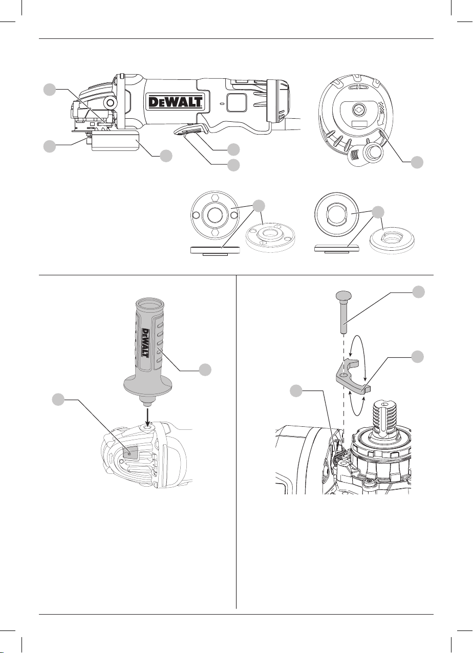
Fig. A
9
2
6
7
8
Fig. B Fig. C
3
1
10
5
4
12
9
13
1
Page 4
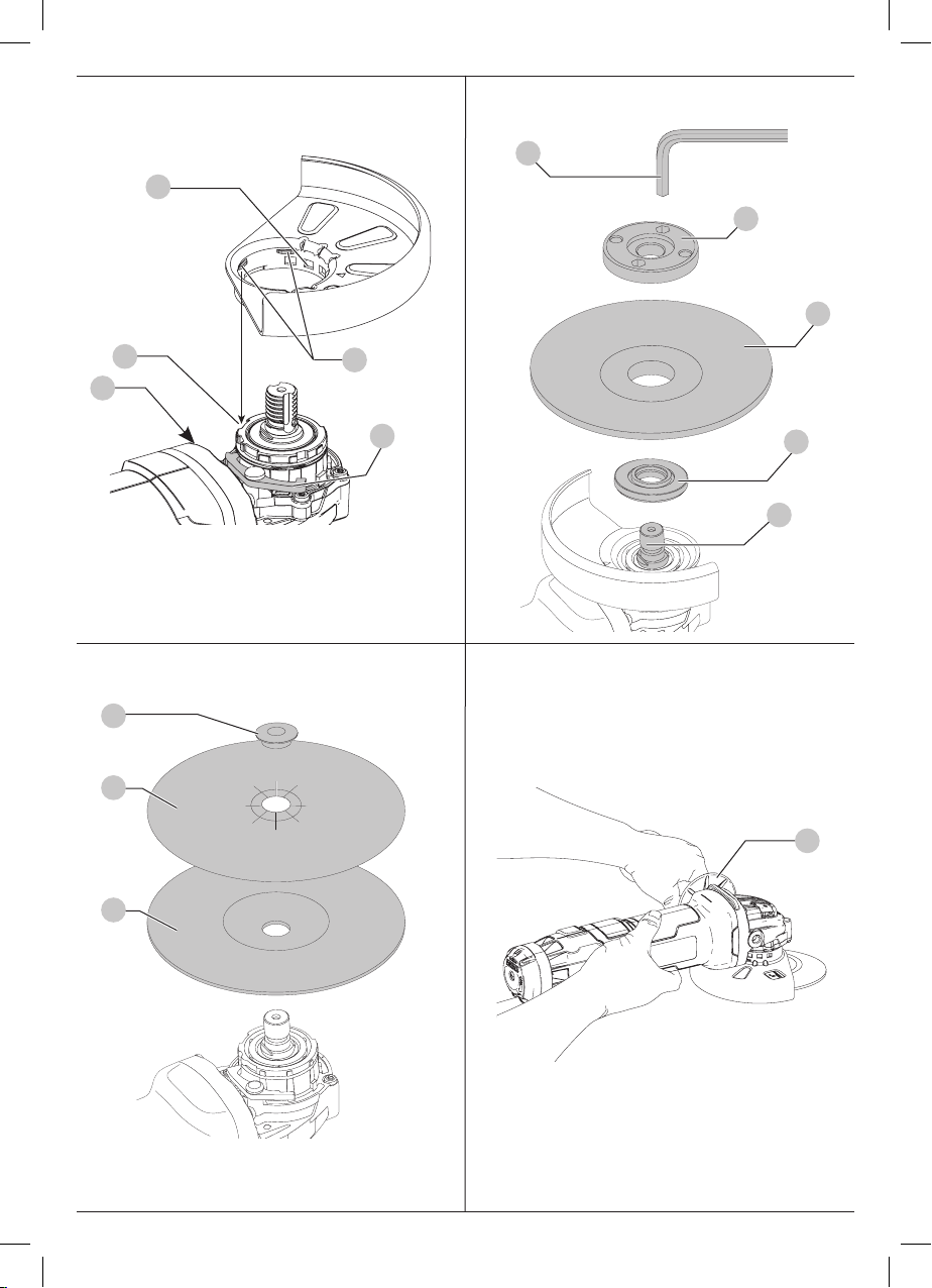
Fig. D
Fig. E
20
15
5
16
14
13
11
9
Fig. F Fig. G
19
18
17
4
2
3
2
Page 5

SMALL ANGLE GRINDERS
DeWALT
DeWALT
DWE4203, DWE4213, DWE4233, DWE4263
Congratulations!
You have chosen a
most reliable partners for professional power toolusers.
Technical Data
Voltage V
Type 3 3 3 1
Power input W
No-load/rated speed min
Wheel diameter mm
Wheel thickness (max) mm
Spindle diameter
Spindle length mm
Weight kg
* weight includes side handle and guard
Noise and vibration total values (triax vector sum) according to EN 60745-2-3:
LPA (emission sound pressure level) dB(A) 92.0 92.0 92.0 –
LWA (sound power level) dB(A) 103.0 103.0 103.0 –
K (uncertainty for the given sound level) dB(A) 3 3 3 –
Surface grinding
Vibration emission value a
Uncertainty K = m/s² 1.5 1.5 1.5 –
Disc sanding
Vibration emission value a
Uncertainty K = m/s² 1.5 1.5 1.5 –
tool. Years of experience, thorough product development and innovation make
DWE4203 DWE4213 DWE4233 DWE4263
230 230 230 230
AC
1010 1200
-1
11,000 11,500 11500 10000
125 125
6.0 6.0
M14 M14
18.5 18.5
1.85 1.85
h,AG
h,DS
=
=
m/s²
m/s²
8.3 8.3 8.3 –
3.0 3.0 3.0 –
1400 1400
125 125
6.0 6.0
M14 M14
18.5 18.5
1.85* 2.5*
one of the
ENGLISH
CAUTION: Working with the wire brush or the abrasive cutting can lead to different vibration levels!
The vibration emission level given in this information sheet has
been measured in accordance with a standardised test given in
EN60745 and may be used to compare one tool with another. It
may be used for a preliminary assessment ofexposure.
WARNING: The declared vibration emission level
represents the main applications of the tool. However if
the tool is used for different applications, with different
accessories or poorly maintained, the vibration emission
may differ. This may significantly increase the exposure
level over the total workingperiod.
An estimation of the level of exposure to vibration should
also take into account the times when the tool is switched
off or when it is running but not actually doing the job.
This may significantly reduce the exposure level over the
total workingperiod.
Identify additional safety measures to protect the operator
from the effects of vibration such as: maintain the tool
and the accessories, keep the hands warm, organisation
of workpatterns.
Fuses:
Europe 230V tools 10 Amperes. mains
U.K. & Ireland 230V tools 13 Amperes. in plugs
3
Page 6
ENGLISH
DeWALT
DeWALT
DeWALT
DeWALT
EC-Declaration of Conformity
Machinery Directive
Small Angle Grinders
DWE4203, DWE4213, DWE4233
declares that these products described under
Technical Data are in compliance with:
2006/42/EC, EN60745-1:2009+A11:2010, EN60745-23:2011+A2:2013+A11:2014 +A12:2014+A13:2015.
These products also comply with Directive 2014/30/EU and
2011/65/EU. For more information, please contact
the following address or refer to the back of themanual.
The undersigned is responsible for compilation of the technical
file and makes this declaration on behalf of
Markus Rompel
Director Engineering
, Richard-Klinger-Straße 11,
D-65510, Idstein, Germany
15.07.16
WARNING: To reduce the risk of injury, read the
instruction manual.
Definitions: Safety Guidelines
The definitions below describe the level of severity for each
signal word. Please read the manual and pay attention to
thesesymbols.
DANGER: Indicates an imminently hazardous
situation which, if not avoided, will result in death or
seriousinjury.
WARNING: Indicates a potentially hazardous situation
which, if not avoided, could result in death or
seriousinjury.
CAUTION: Indicates a potentially hazardous situation
which, if not avoided, may result in minor or
moderateinjury.
NOTICE: Indicates a practice not related to
personal injury which, if not avoided, may result in
propertydamage.
Denotes risk of electricshock.
Denotes risk offire.
General Power Tool Safety Warnings
WARNING: Read all safety warnings and all
instructions. Failure to follow the warnings and
instructions may result in electric shock, fire and/or
seriousinjury.
SAVE ALL WARNINGS AND INSTRUCTIONS
FOR FUTURE REFERENCE
The term “power tool” in the warnings refers to your mainsoperated (corded) power tool or battery-operated (cordless)
powertool.
1) Work area safety
a ) Keep work area clean and well lit. Cluttered or dark
areas inviteaccidents.
b ) Do not operate power tools in explosive
atmospheres, such as in the presence of flammable
liquids, gases or dust. Power tools create sparks which
may ignite the dust orfumes.
at
.
c ) Keep children and bystanders away while operating
a power tool. Distractions can cause you to losecontrol.
2) Electrical safety
a ) Power tool plugs must match the outlet. Never
modify the plug in any way. Do not use any adapter
plugs with earthed (grounded) power tools.
Unmodified plugs and matching outlets will reduce risk of
electricshock.
b ) Avoid body contact with earthed or grounded
surfaces such as pipes, radiators, ranges and
refrigerators. There is an increased risk of electric shock if
your body is earthed orgrounded.
c ) Do not expose power tools to rain or wet conditions.
Water entering a power tool will increase the risk of
electricshock.
d ) Do not abuse the cord. Never use the cord for
carrying, pulling or unplugging the power tool. Keep
cord away from heat, oil, sharp edges or moving
parts. Damaged or entangled cords increase the risk of
electricshock.
e ) When operating a power tool outdoors, use an
extension cord suitable for outdoor use. Use of a cord
suitable for outdoor use reduces the risk of electricshock.
f ) If operating a power tool in a damp location is
unavoidable, use a residual current device (RCD)
protected supply. Use of an RCD reduces the risk of
electricshock.
3) Personal safety
a ) Stay alert, watch what you are doing and use
common sense when operating a power tool. Do not
use a power tool while you are tired or under the
influence of drugs, alcohol or medication. A moment
of inattention while operating power tools may result in
serious personalinjury.
b ) Use personal protective equipment. Always wear
eye protection. Protective equipment such as dust mask,
non-skid safety shoes, hard hat, or hearing protection used
for appropriate conditions will reduce personalinjuries.
c ) Prevent unintentional starting. Ensure the switch
is in the off position before connecting to power
source and/or battery pack, picking up or carrying
the tool. Carrying power tools with your finger on the
4
Page 7

switch or energising power tools that have the switch on
invitesaccidents.
d ) Remove any adjusting key or wrench before turning
the power tool on. A wrench or a key left attached
to a rotating part of the power tool may result in
personalinjury.
e ) Do not overreach. Keep proper footing and balance
at all times. This enables better control of the power tool
in unexpectedsituations.
f ) Dress properly. Do not wear loose clothing or
jewellery. Keep your hair, clothing and gloves away
from moving parts. Loose clothes, jewellery or long hair
can be caught in movingparts.
g ) If devices are provided for the connection of dust
extraction and collection facilities, ensure these are
connected and properly used. Use of dust collection
can reduce dust-relatedhazards.
4) Power tool use and care
a ) Do not force the power tool. Use the correct power
tool for your application. The correct power tool
will do the job better and safer at the rate for which it
wasdesigned.
b ) Do not use the power tool if the switch does not turn
it on and off. Any power tool that cannot be controlled
with the switch is dangerous and must berepaired.
c ) Disconnect the plug from the power source and/or
the battery pack from the power tool before making
any adjustments, changing accessories, or storing
power tools. Such preventive safety measures reduce the
risk of starting the power toolaccidentally.
d ) Store idle power tools out of the reach of children
and do not allow persons unfamiliar with the power
tool or these instructions to operate the power tool.
Power tools are dangerous in the hands of untrainedusers.
e ) Maintain power tools. Check for misalignment or
binding of moving parts, breakage of parts and any
other condition that may affect the power tool’s
operation. If damaged, have the power tool repaired
before use. Many accidents are caused by poorly
maintained powertools.
f ) Keep cutting tools sharp and clean. Properly
maintained cutting tools with sharp cutting edges are less
likely to bind and are easier tocontrol.
g ) Use the power tool, accessories and tool bits etc.,
in accordance with these instructions taking into
account the working conditions and the work to be
performed. Use of the power tool for operations different
from those intended could result in a hazardoussituation.
5) Service
a ) Have your power tool serviced by a qualified repair
person using only identical replacement parts. This
will ensure that the safety of the power tool ismaintained.
ENGLISH
ADDITIONAL SPECIFIC SAFETY RULES
Safety Instructions for All Operations
a ) This power tool is intended to function as a
grinder, sander, wire brush or cut-off tool. Read
all safety warnings, instructions, illustrations and
specifications provided with this power tool. Failure
to follow all instructions listed below may result in electric
shock, fire and/or seriousinjury.
b ) Operations such as polishing are not recommended
to be performed with this power tool. Operations for
which the power tool was not designed may create a
hazard and cause personalinjury.
c ) Do not use accessories which are not specifically
designed and recommended by the tool
manufacturer. Just because the accessory can
be attached to your power tool, it does not assure
safeoperation.
d ) The rated speed of the accessory must be at least
equal to the maximum speed marked on the power
tool. Accessories running faster than their rated speed can
break and flyapart.
e ) The outside diameter and the thickness of your
accessory must be within the capacity rating of
your power tool. Incorrectly sized accessories can not be
adequately guarded orcontrolled.
f ) Threaded mounting of accessories must match the
grinder spindle thread. For accessories mounted by
flanges, the arbour hole of the accessory must fit the
locating diameter of the flange. Accessories that do
not match the mounting hardware of the power tool will
run out of balance, vibrate excessively and may cause loss
ofcontrol.
g ) Do not use a damaged accessory. Before each use
inspect the accessory such as abrasive wheel for
chips and cracks, backing pad for cracks, tear or
excess wear, wire brush for loose or cracked wires.
If power tool or accessory is dropped, inspect for
damage or install an undamaged accessory. After
inspecting and installing an accessory, position
yourself and bystanders away from the plane of
the rotating accessory and run the power tool at
maximum no-load speed for one minute. Damaged
accessories will normally break apart during this testtime.
h ) Wear personal protective equipment. Depending on
application, use face shield, safety goggles or safety
glasses. As appropriate, wear dust mask, hearing
protectors, gloves and workshop apron capable of
stopping small abrasive or workpiece fragments.
The eye protection must be capable of stopping flying
debris generated by various operations. The dust mask or
respirator must be capable of filtrating particles generated
by your operation. Prolonged exposure to high intensity
noise may cause hearingloss.
5
Page 8

ENGLISH
i ) Keep bystanders a safe distance away from work
area. Anyone entering the work area must wear
personal protective equipment. Fragments of
workpiece or of a broken accessory may fly away and
cause injury beyond immediate area ofoperation.
j ) Hold the power tool by insulated gripping surfaces
only, when performing an operation where the
cutting accessory may contact hidden wiring or its
own cord. Cutting accessory contacting a "live" wire may
make exposed metal parts of the power tool "live" and
could give the operator an electricalshock.
k ) Position the cord clear of the spinning accessory. If
you lose control, the cord may be cut or snagged and your
hand or arm may be pulled into the spinningaccessory.
l ) Never lay the power tool down until the accessory
has come to a complete stop. The spinning accessory
may grab the surface and pull the power tool out of
yourcontrol.
m ) Do not run the power tool while carrying it at your
side. Accidental contact with the spinning accessory
could snag your clothing, pulling the accessory into
yourbody.
n ) Regularly clean the power tool’s air vents. The
motor’s fan will draw the dust inside the housing and
excessive accumulation of powdered metal may cause
electricalhazards.
o ) Do not operate the power tool near flammable
materials. Sparks could ignite thesematerials.
p ) Do not use accessories that require liquid coolants.
Using water or other liquid coolants may result in
electrocution orshock.
q ) Do not use Type 11 (flaring cup) wheels on this tool.
Using inappropriate accessories can result ininjury.
r ) Always use side handle. Tighten the handle securely.
The side handle should always be used to maintain control
of the tool at alltimes.
FURTHER SAFETY INSTRUCTIONS FOR ALL
OPERATIONS
Causes and Operator Prevention
of Kickback
Kickback is a sudden reaction to a pinched or snagged rotating
wheel, backing pad, brush or any other accessory. Pinching or
snagging causes rapid stalling of the rotating accessory which
in turn causes the uncontrolled power tool to be forced in the
direction opposite of the accessory’s rotation at the point of
thebinding.
For example, if an abrasive wheel is snagged or pinched by the
workpiece, the edge of the wheel that is entering into the pinch
point can dig into the surface of the material causing the wheel
to climb out or kick out. The wheel may either jump toward or
away from the operator, depending on direction of the wheel’s
movement at the point of pinching. Abrasive wheels may also
break under theseconditions.
Kickback is the result of tool misuse and/or incorrect operating
procedures or conditions and can be avoided by taking proper
precautions as given below:
a ) Maintain a firm grip on the power tool and position
your body and arm to allow you to resist kickback
forces. Always use auxiliary handle, if provided, for
maximum control over kickback or torque reaction
during start up. The operator can control torque reaction
or kickback forces, if proper precautions aretaken.
b ) Never place your hand near the rotating accessory.
Accessory may kickback over yourhand.
c ) Do not position your body in the area where power
tool will move if kickback occurs. Kickback will propel
the tool in direction opposite to the wheel’s movement at
the point ofsnagging.
d ) Use special care when working corners, sharp edges
etc. Avoid bouncing and snagging the accessory.
Corners, sharp edges or bouncing have a tendency to
snag the rotating accessory and cause loss of control
orkickback.
e ) Do not attach a saw chain woodcarving blade or
toothed saw blade. Such blades create frequent kickback
and loss ofcontrol.
Safety Warnings Specific for Grinding and
Abrasive Cutting-Off Operations
a ) Use only wheel types that are recommended for your
power tool and the specific guard designed for the
selected wheel. Wheels for which the power tool was not
designed cannot be adequately guarded and areunsafe.
b ) The grinding surface of centre depressed wheels
must be mounted below the plane of the guard lip.
An improperly mounted wheel that projects through the
plane of the guard lip cannot be adequatelyprotected.
c ) The guard must be securely attached to the power
tool and positioned for maximum safety, so the least
amount of wheel is exposed towards the operator.
The guard helps to protect the operator from broken wheel
fragments, accidental contact with wheel and sparks that
could igniteclothing.
d ) Wheels must be used only for recommended
applications. For example: do not grind with the side
of cut-off wheel. Abrasive cut-off wheels are intended
for peripheral grinding, side forces applied to these wheels
may cause them toshatter.
e ) Always use undamaged wheel flanges that are
of correct size and shape for your selected wheel.
Proper wheel flanges support the wheel thus reducing the
possibility of wheel breakage. Flanges for cut-off wheels
may be different from grinding wheelflanges.
f ) Do not use worn down wheels from larger power
tools. Wheel intended for larger power tool is not suitable
for the higher speed of a smaller tool and mayburst.
6
Page 9

Additional Safety Warnings Specific for
DeWALT
DeWALT
Abrasive Cutting-Off Operations
a ) Do not "jam" the cut-off wheel or apply excessive
pressure. Do not attempt to make an excessive depth
of cut. Overstressing the wheel increases the loading and
susceptibility to twisting or binding of the wheel in the cut
and the possibility of kickback or wheelbreakage.
b ) Do not position your body in line with and behind
the rotating wheel. When the wheel, at the point of
operations, is moving away from your body, the possible
kickback may propel the spinning wheel and the power
tool directly atyou.
c ) When wheel is binding or when interrupting a cut
for any reason, switch off the power tool and hold
the power tool motionless until the wheel comes to
a complete stop. Never attempt to remove the cutoff wheel from the cut while the wheel is in motion
otherwise kickback may occur. Investigate and take
corrective action to eliminate the cause of wheelbinding.
d ) Do not restart the cutting operation in the
workpiece. Let the wheel reach full speed and
carefully re-enter the cut. The wheel may bind, walk up
or kickback if the power tool is restarted in theworkpiece.
e ) Support panels or any oversized workpiece to
minimize the risk of wheel pinching and kickback.
Large workpieces tend to sag under their own weight.
Supports must be placed under the workpiece near the line
of cut and near the edge of the workpiece on both sides
of thewheel.
f ) Use extra caution when making a “pocket cut” into
existing walls or other blind areas. The protruding
wheel may cut gas or water pipes, electrical wiring or
objects that can causekickback.
Safety Warnings Specific for Sanding
Operations
a ) Do not use excessively oversized sanding disc
paper. Follow manufacturer’s recommendations,
when selecting sanding paper. Larger sanding paper
extending beyond the sanding pad presents a laceration
hazard and may cause snagging, tearing of the disc
orkickback.
Safety Warnings Specific for Wire Brushing
Operations
a ) Be aware that wire bristles are thrown by the brush
even during ordinary operation. Do not overstress
the wires by applying excessive load to the brush.
The wire bristles can easily penetrate llight clothing and/
orskin.
ENGLISH
b ) If the use of a guard is recommended for wire
brushing, do not allow any interference of the
wire wheel or brush with the guard. Wire wheel
or brush may expand in diameter due to work and
centrifugalforces.
Additional Safety Rules for Grinders
• Threaded mounting of accessories must match the grinder
spindle thread. For accessories mounted by flanges, the arbor
hole of the accessory must fit the locating diameter of the
flange. Accessories that do not match the mounting hardware
of the power tool will run out of balance, vibrate excessively
and may cause loss ofcontrol.
• The grinding surface of the centre depressed wheels must
be mounted below the plane of the guard lip. An improperly
mounted wheel that projects through the plane of the guard
lip cannot be adequatelyprotected.
WARNING: We recommend the use of a residual current
device with a residual current rating of 30mA or less.
Residual Risks
In spite of the application of the relevant safety regulations
and the implementation of safety devices, certain residual risks
cannot be avoided. These are:
• Impairment ofhearing.
• Risk of personal injury due to flyingparticles.
• Risk of burns due to accessories becoming hot
duringoperation.
• Risk of personal injury due to prolongeduse.
• Risk of dust from hazardoussubstances.
Electrical Safety
The electric motor has been designed for one voltage only.
Always check that the power supply corresponds to the voltage
on the rating plate.
Your
with EN60745; therefore no earth wire is required.
If the supply cord is damaged, it must be replaced by a
specially prepared cord available through the
serviceorganisation.
Mains Plug Replacement
(U.K. & Ireland Only)
If a new mains plug needs to be fitted:
• Safely dispose of the oldplug.
• Connect the brown lead to the live terminal in theplug.
• Connect the blue lead to the neutralterminal.
WARNING: No connection is to be made to the
earthterminal.
Follow the fitting instructions supplied with good quality plugs.
Recommended fuse: 13A.
tool is double insulated in accordance
7
Page 10

ENGLISH
Using an Extension Cable
An extension cord should not be used unless absolutely
necessary. Use an approved extension cable suitable for
the power input of your charger (see Technical Data). The
minimum conductor size is 1.5 mm2; the maximum length
is30m.
When using a cable reel, always unwind the cablecompletely.
Package Contents
The package contains:
1 Angle grinder
1 Guard
1 Side handle
1 Backing flange
1 Threaded clamp nut
1 Hex key
1 Instruction manual
• Check for damage to the tool, parts or accessories which may
have occurred duringtransport.
• Take the time to thoroughly read and understand this manual
prior tooperation.
Markings on Tool
The following pictograms are shown on the tool:
Read instruction manual before use.
Wear ear protection.
Wear eye protection.
Date Code Position (Fig. D)
The date code
is printed into thehousing.
Example:
11
, which also includes the year of manufacture,
2016 XX XX
Year of Manufacture
Description (Fig. A, B)
WARNING: Never modify the power tool or any part of it.
Damage or personal injury couldresult.
1
Spindle lock button
2
Spindle
3
Side handle
4
Backing flange
5
Clamp nut
6
Guard
7
Paddle switch
8
Lock-off lever
9
Guard release lever
10
Dust ejection system
Intended Use
Your heavy-duty small angle grinder has been designed
for professional grinding, sanding, wire brushing and
cuttingapplications.
DO NOT use grinding wheels other than centre depressed
wheels and flapdiscs.
DO NOT use under wet conditions or in the presence of
flammable liquids orgases.
Your heavy-duty angle grinder is a professional power tool.
DO NOT let children come into contact with the tool.
Supervision is required when inexperienced operators use
thistool.
• Young children and the infirm. This appliance is not
intended for use by young children or infirm persons
without supervision.
• This product is not intended for use by persons (including
children) suffering from diminished physical, sensory or
mental abilities; lack of experience, knowledge or skills
unless they are supervised by a person responsible for their
safety. Children should never be left alone with thisproduct.
Anti-vibration Side Handle
The anti-vibration side handle offers added comfort by
absorbing the vibrations caused by thetool.
Dust Ejection System (Fig. A)
The dust ejection system
the guard and motor inlet, and minimises the amount of dust
entering the motorhousing.
10
prevents dust pile-up around
Soft Start Feature
DWE4263
The soft start feature allows a slow speed build-up to avoid an
initial jerk when starting. This feature is particularly useful when
working in confinedspaces.
ASSEMBLY AND ADJUSTMENTS
WARNING: To reduce the risk of serious personal
injury, turn tool off and disconnect tool from power
source before making any adjustments or removing/
installing attachments or accessories. Be sure the
trigger switch is in the OFF position. An accidental start-up
can cause injury.
Attaching Side Handle (Fig. B)
WARNING: Before using the tool, check that the handle is
tightenedsecurely.
Screw the side handle
side of the gear case. The side handle should always be used to
maintain control of the tool at alltimes.
3
tightly into one of the holes on either
Guards
CAUTION: Guards must be used with all grinding
wheels, cutting wheels, sanding flap discs, wire
brushes, and wire wheels. The tool may be used
without a guard only when sanding with conventional
8
Page 11

sanding discs. Refer to Figure A to see guards provided
with the unit. Some applications may require purchasing
the correct guard from your local dealer or authorized
service centre.
NOTE: Edge grinding and cutting can be performed with Type
27 wheels designed and specified for this purpose; 6.35 mm
thick wheels are designed for surface grinding while thinner
Type 27 wheels need to be examined for the manufacturer's
label to see if they can be used for surface grinding or only
edge grinding/cutting. A Type 1 guard must be used for any
wheel where surface grinding is forbidden. Cutting can also be
performed by using a Type41 wheel and a Type 1guard.
NOTE: See the Accessories Chart to select the proper guard /
accessory combination.
Adjusting and Mounting Guard (Fig. C, D)
CAUTION: Turn unit off and unplug the tool before
making any adjustments or removing or installing
attachments or accessories.
CAUTION: BEFORE operating the tool, identify which
guard adjustment option your tool is set to.
Adjustment Options
Two-Touch
9
engages one of
TM
15
on the guard
For guard adjustment, the guard release lever
the alignment holes
feature. Your grinder offers two options for this adjustment.
• One-touchTM: In this position the engaging face is slanted
and will ride over to the next alignment hole when guard
is rotated in a clockwise direction (spindle facing user) but
self-locks in the anti-clockwise direction.
• Two-touchTM: In this position the engaging face is straight
and squared off. It will NOT ride over to the next alignment
hole unless guard release lever is pressed and held while
simultaneously rotating the guard in either a clockwise or
anti-clockwise direction (spindle facing user).
Setting Guard Adjustment Options
To adjust the guard release lever
adjustmentoption:
1. Remove screw
2. Remove the guard release lever taking note of the spring
position. Choose the end of the lever for the desired
adjustment option. One-touch will use the slanted end of
the lever
collar. Two-touch will use the squaredend to engage the
alignmnet holes
3. Replace the lever, positioning the chosen end under the
spring
thespring.
15
on the guard collar using a ratcheting
TM
One-Touch
9
for desired
12
using a T20 bit.
9
to engage the alignment holes
15
on the guard collar.
13
. Ensure the lever is in proper contact with
ENGLISH
4. Replace screw and torque to 2.0-3.0N-m. Ensure proper
installation with spring return function by depressing guard
release lever
Mounting Guard (Fig. D)
1. With the spindle facing the operator, press and hold the
guard release lever
2. Align the lugs
gearcase.
3. Push the guard down until the guard lugs engage and
rotate them in the groove on the gear case hub. Release the
guard release lever.
4. To position the guard:
One-touchTM: Rotate the guard clockwise into the desired
working position. Press and hold the guard release lever
release lever to rotate the guard in the anti-clockwise
direction.
Two-touchTM: Press and hold the guard release lever
Rotate the guard clockwise or anti-clockwise into the
desired working position.
NOTE: The guard body should be positioned between the
spindle and the operator to provide maximum operator
protection.
The guard release lever should snap into one of the
alignment holes
the guard is secure.
5. To remove the guard, follow steps 1–3 of these instructions
in reverse.
9
.
CAUTION: Prior to mounting guard, ensure the screw,
lever, and spring are fitted correctly before mounting
theguard.
9
.
13
on the guard with the slots
15
on the guard collar. This ensures that
14
on the
9
Flanges and Wheels
Mounting Non-Hubbed Wheels (Fig. E)
WARNING: Failure to properly seat the flange/ clamp nut/
wheel could result in serious injury (or damage to the tool
or wheel).
CAUTION: Included flanges must be used with depressed
centre Type 27 and Type 42 grinding wheels and Type41
cutting wheels. See the Accessories Chart for more
information.
WARNING: A closed, two-sided cutting wheel guard is
re quired when using cutting wheels.
WARNING: Use of a damaged flange or guard or fail ure
to use proper flange and guard can re sult in injury due to
wheel breakage and wheel contact. See the Accessories
Chart for more information.
1. Place the tool on a table, guard up.
2. Install the unthreaded backing flange
the raised centre (pilot) facing the wheel.
3. Place wheel
wheel on the raised centre (pilot) of the backing flange.
4. While depressing the spindle lock button and with the
hex depressions facing away from the wheel, thread the
clampnut
slots in the spindle.
16
against the backing flange, centreing the
5
on spindle so that the lugs engage the two
4
on spindle
2
with
9
.
9
Page 12

ENGLISH
5. While depressing the spindle lock button, tighten the
locking flange with a wrench
6. To remove the wheel, depress the spindle lock button and
loosen the threaded locking flange with a wrench.
Mounting Sanding Backing Pads (Fig. F)
NOTE: Use of a guard with sanding discs that use backing pads,
often called fiber resin discs, is not required. Since a guard is
not required for these accessories, the guard may or may not fit
correctly if used.
WARNING: Failure to properly seat the flange/ clamp nut/
wheel could result in serious injury (or damage to the tool
or wheel).
WARNING: Proper guard must be reinstalled for grinding
wheel, cutting wheel, sanding flap disc, wire brush or
wire wheel applications after sanding applications are
complete.
1. Place or appropriately thread backing pad
thespindle.
2. Place the sanding disc
3. While depressing spindle lock
spindle, piloting the raised hub on the clamp nut into the
centre of san ding disc and backingpad.
4. Tighten the clamp nut by hand. Then depress the spindle
lock button while turning the sanding disc until the sanding
disc and clamp nut are snug.
5. To remove the wheel, grasp and turn the backing pad and
sanding pad while depressing the spindle lock button.
Mounting and Removing Hubbed Wheels
(Fig. A)
Hubbed wheels install directly on the M14 threaded spindle.
Thread of accessory must match thread of spindle.
1. Remove backing flange by pulling away from tool.
2. Thread the wheel on the spindle
3. Depress the spindle lock button
tighten the hub of the wheel.
4. Reverse the above procedure to remove the wheel.
NOTICE: Failure to properly seat the wheel before turning
the tool on may result in damage to the tool or the wheel.
Mounting Wire Cup Brushes and
Wire Wheels (Fig. A)
WARNING: Failure to properly seat the flange/ clamp nut/
wheel could result in serious injury (or damage to the tool
or wheel).
CAUTION: To reduce the risk of personal injury,
wear work gloves when handling wire brushes and
wheels. They can become sharp.
CAUTION: To reduce the risk of damage to the tool,
wheel or brush must not touch guard when mounted
or while in use. Undetectable damage could occur to
the accessory, causing wires to fragment from accessory
wheel or cup.
20
.
18
on the backing pad
1
, thread clamp nut
2
by hand.
1
and use a wrench to
17
on
17
.
19
on
Wire cup brushes or wire wheels install directly on the threaded
spindle without the use of flanges. Use only wire brushes or
wheels provided with a M14 threaded hub. These accessories
are available at extra cost from your local dealer or authorised
service centre.
1. Place the tool on a table, guard up.
2. Thread the wheel on the spindle by hand.
3. Depress spindle lock button
hub of the wire wheel or brush to tighten the wheel.
4. To remove the wheel, reverse the above procedure.
NOTICE: To reduce the risk of damage to the tool, properly
seat the wheel hub before turning the tool on.
1
and use a wrench on the
Prior to Operation
• Install the guard and appropriate disc or wheel. Do not use
excessively worn discs orwheels.
• Be sure the inner and outer flange are mounted correctly.
Follow the instructions given in the Grinding and Cutting
AccessoryChart.
• Make sure the disc or wheel rotates in the direction of the
arrows on the accessory and thetool.
• Do not use a damaged accessory. Before each use inspect
the accessory such as abrasive wheels for chips and cracks,
backing pad for cracks, tear or excess wear, wire brush for
loose or cracked wires. If power tool or accessory is dropped,
inspect for damage or install an undamaged accessory. After
inspecting and installing an accessory, position yourself and
bystanders away from the plane of the rotating accessory
and run the power tool at maximum no-load speed for one
minute. Damaged accessories will normally break apart
during this testtime.
OPERATION
Instructions for Use
WARNING: Always observe the safety instructions and
applicableregulations.
WARNING: To reduce the risk of serious personal
injury, turn tool off and disconnect tool from power
source before making any adjustments or removing/
installing attachments or accessories. Be sure the
trigger switch is in the OFF position. An accidental start-up
can cause injury.
WARNING:
• Ensure all materials to be ground or cut are secured
inplace.
• Secure and support the workpiece. Use clamps or a
vice to hold and support the workpiece to a stable
platform. It is important to clamp and support the
workpiece securely to prevent movement of the
workpiece and loss of control. Movement of the
workpiece or loss of control may create a hazard and
cause personalinjury.
10
Page 13

• Support panels or any oversized workpiece
to minimize the risk of wheel pinching and
kickback. Large workpieces tend to sag under their
own weight. Supports must be placed under the
workpiece near the line of cut and near the edge of the
workpiece on both sides of thewheel.
• Always wear regular working gloves while operating
thistool.
• The gear becomes very hot duringuse.
• Apply only a gentle pressure to the tool. Do not exert
side pressure on thedisc.
• Always install the guard and appropriate disc or
wheel. Do not use excessively worn disc or wheel.
• Be sure the inner and outer flange are
mountedcorrectly.
• Make sure the disc or wheel rotates in the direction of
the arrows on the accessory and thetool.
• Avoid overloading. Should the tool become hot, let it
run a few minutes under no load condition to cool the
accessory. Do not touch accessories before they have
cooled. The discs become very hot duringuse.
• Never work with the grinding cup without a suitable
protection guard inplace.
• Do not use the power tool with a cut-offstand.
• Never use blotters together with bonded
abrasiveproducts.
• Be aware, the wheel continues to rotate after the tools
is switchedoff.
Proper Hand Position (Fig. G)
WARNING: To reduce the risk of serious personal injury,
ALWAYS use proper hand position asshown.
WARNING: To reduce the risk of serious personal
injury, ALWAYS hold securely in anticipation of a
suddenreaction.
Proper hand position requires one hand on the side handle
with the other hand on the body of the tool, as shown in
FigureG.
3
Paddle Switch (Fig. A)
CAUTION: Hold the side handle and body of the tool
firmly to maintain control of the tool at start up and
during use and until the wheel or accessory stops rotating.
Make sure the wheel has come to a complete stop be fore
laying the tooldown.
NOTE: To reduce unexpected tool movement, do not switch
the tool on or off while under load conditions. Allow the grinder
to run up to full speed before touching the work surface. Lift the
tool from the surface before turning the tool off. Allow the tool
to stop rotating before putting itdown.
1. To turn the tool on, push the lock-off lever
back of the tool, then depress the paddle switch
will run while the switch isdepressed.
2. Turn the tool off by releasing the paddleswitch.
8
toward the
7
. The tool
Spindle Lock (Fig. B)
The spindle lock
rotating when installing or removing wheels. Operate the
spindle lock only when the tool is turned off, unplugged from
the power supply, and has come to a completestop.
To engage the lock, depress the spindle lock button and rotate
the spindle until you are unable to rotate the spindlefurther.
1
is provided to prevent the spindle from
NOTICE: To reduce the risk of damage to the tool, do
not engage the spindle lock while the tool is operating.
Damage to the tool will result and attached accessory
may spin off possibly resulting ininjury.
Surface Grinding, Sanding and Wire
Brushing
CAUTION: Always use the correct guard per the
instructions in this manual.
WARNING: Metal dust build-up. Extensive use of flap
discs in metal applications can result in the increased
potential for electric shock. To reduce this risk, insert an
RCD before use and clean the ventilation slots daily by
blowing dry compressed air into the ventilation slots
inaccordance with the below maintenanceinstructions.
To perform work on a the surface of a workpiece:
1. Allow the tool to reach full speed before touching the tool
to the work surface.
2. Apply minimum pressure to the work surface, allowing
the tool to operate at high speed. Material removal rate is
greatest when the tool operates at high speed.
Angle
3. Maintain an appropriate angle between the tool and work
,
surface. Refer to the chart according to particularfunction.
Function Angle
Grinding 20˚-30˚
Sanding with Flap Disc 5˚-10˚
Sanding with Backing Pad 5˚-15˚
Wire Brushing 5˚-10˚
4. Maintain contact between the edge of the wheel and the
work surface.
- If grinding, sanding with flap discs or wire brushing
move the tool continuously in a forward and back
motion to avoid creating gouges in the worksurface.
- If sanding with a backing pad, move the tool constantly
in a straight line to prevent burning and swirling of
worksurface.
NOTE: Allowing the tool to rest on the work surface without
moving will damage the work piece.
ENGLISH
11
Page 14

ENGLISH
5. Remove the tool from work surface before turning tool off.
Allow the tool to stop rotating before laying it down.
CAUTION: Use extra care when working over an edge, as
a sudden sharp movement of grinder may be experienced.
Precautions To Take When Working on a
Painted Workpiece
1. Sanding or wire brushing of lead based paint is NOT
RECOMMENDED due to the difficulty of controlling the
contaminated dust. The greatest danger of lead poisoning is
to children and pregnant women.
2. Since it is difficult to identify whether or not a paint contains
lead without a chemical analysis, we recommend the
following precautions when sanding any paint:
Personal Safety
1. No children or pregnant women should enter the work area
where the paint sanding or wire brushing is being done
until all clean up is completed.
2. A dust mask or respirator should be worn by all persons
entering the work area. The filter should be replaced daily or
whenever the wearer has difficulty breathing.
NOTE: Only those dust masks suitable for working with lead
paint dust and fumes should be used. Ordinary painting
masks do not offer this protection. See your local hardware
dealer for the proper N.I.O.S.H. approved mask.
3. NO EATING, DRINKING or SMOKING should be done in the
work area to prevent ingesting contaminated paint particles.
Workers should wash and clean up BEFORE eating, drinking
or smoking. Articles of food, drink, or smoking should not be
left in the work area where dust would settle on them.
Environmental Safety
1. Paint should be removed in such a manner as to minimize
the amount of dust generated.
2. Areas where paint removal is occurring should be sealed
with plastic sheeting of 4 mils thickness.
3. Sanding should be done in a manner to reduce tracking of
paint dust outside the work area.
Cleaning and Disposal
1. All surfaces in the work area should be vacuumed and
thoroughly cleaned daily for the duration of the sanding
project. Vacuum filter bags should be changedfrequently.
2. Plastic drop cloths should be gathered up and disposed
of along with any dust chips or other removal debris. They
should be placed in sealed refuse receptacles and disposed
of through regular trash pick-up procedures.
During clean up, children and pregnant women should be
kept away from the immediate work area.
3. All toys, washable furniture and utensils used by children
should be washed thoroughly before being used again.
Edge Grinding and Cutting
WARNING: Do not use edge grinding/cutting wheels for
surface grinding applications because these wheels are
not designed for side pressures encountered with surface
grinding. Wheel breakage and injury may result.
12
CAUTION: Wheels used for edge grinding and cutting
may break or kick back if they bend or twist while the tool
is being used. In all edge grinding/cutting operations, the
open side of the guard must be positioned away from
theoperator.
NOTICE: Edge grinding/cutting with a Type27 wheel
must be limited to shallow cutting and notching—less
than 13mm in depth when the wheel is new. Reduce the
depth of cutting/notching equal to the reduction of the
wheel radius as it wears down. Refer to the Accessories
Chart for more information. Edge grinding/cutting with a
Type 41 wheel requires usage of a Type 1 guard.
1. Allow the tool to reach full speed before touching the tool
to the work surface.
2. Apply minimum pressure to the work surface, allowing
the tool to operate at high speed. Grinding/cutting rate is
greatest when the tool operates at high speed.
3. Position yourself so that the open-underside of the wheel is
facing away from you.
4. Once a cut is begun and a notch is established in the
workpiece, do not change the angle of the cut. Changing
the angle will cause the wheel to bend and may cause
wheel breakage. Edge grinding wheels are not designed to
withstand side pressures caused bybending.
5. Remove the tool from the work surface before turning
the tool off. Allow the tool to stop rotating before laying
itdown.
Metal Applications
When using the tool in metal applications, make sure that a
residual current device (RCD) has been inserted to avoid residual
risks caused by metal swarf.
If the power supply is shut off by the RCD, take the tool to an
authorised DeWALT repair agent.
WARNING: In extreme working conditions, conductive
dust can accumulate inside the machine housing when
working with metal. This can result in the protective
insulation in the machine becoming degraded with a
potential risk of an electrical shock.
To avoid build-up of metal swarf inside the machine, we
recommend to clear the ventilation slots on a daily basis. Refer
to Maintenance.
Cutting Metal
For cutting with bonded abrasives, always use the
guardtype 1.
When cutting, work with moderate feed, adapted to the
material being cut. Do not exert pressure onto the cutting disc,
tilt or oscillate the machine.
Do not reduce the speed of running down cutting discs by
applying sideward pressure.
The machine must always work in an upgrinding motion.
Otherwise, the danger exists of it being pushed uncontrolled
out of the cut.
When cutting profiles and square bar, it is best to start at the
smallest cross section.
Page 15

ENGLISH
DeWALT
DeWALT
DeWALT
D
b
D
D
d
D
Rough Grinding
Never use a cutting disc for roughing.
Always use the guard type 27.
The best roughing results are achieved when setting the
machine at an angle of 30° to 40°. Move the machine back and
forth with moderate pressure. In this manner, the workpiece
will not become too hot, does not discolour and no grooves
areformed.
Cutting Stone
The machine shall be used only for dry cutting.
For cutting stone, it is best to use a diamond cutting disc.
Operate the machine only with additional dust protection mask.
Working Advice
Exercise caution when cutting slots in structural walls.
Slots in structural walls are subject to the country-specific
regulations. These regulations are to be observed under all
circumstances.Before beginning work, consult the responsible
structural engineer, architect or the construction supervisor.
MAINTENANCE
Your
over a long period of time with a minimum of maintenance.
Continuous satisfactory operation depends upon proper tool
care and regularcleaning.
power tool has been designed to operate
WARNING: To reduce the risk of serious personal
injury, turn tool off and disconnect tool from power
source before making any adjustments or removing/
installing attachments or accessories. Be sure the
trigger switch is in the OFF position. An accidental start-up
can cause injury.
Pop-off Brushes
The motor will be automatically shut off indicating that the
carbon brushes are nearly worn out and that the tool needs
servicing. The carbon brushes are not user-serviceable. Take the
tool to an authorised DeWALT repairagent.
Lubrication
Your power tool requires no additionallubrication.
Optional Accessories
WARNING: Since accessories, other than those offered
by
of such accessories with this tool could be hazardous.
To reduce the risk of injury, only
accessories should be used with thisproduct.
Consult your dealer for further information on the
appropriateaccessories.
b
, have not been tested with this product, use
Max.
[mm]
D b d
d
115 6 22,23 11,500 80 –
125 6 22,23 11,500 80 –
115 – – 11,500 80 –
125 – – 11,500 80 –
75 30 M14 11,500 45 20.0
115 12 M14 11,500 80 20.0
125 12 M14 11,500 80 20.0
[mm]
Min.
Rotation
[min.–1]
recommended
Periphical
speed
hole length
[m/s]
Threaded
[mm]
Protecting the Environment
Separate collection. Products and batteries marked
with this symbol must not be disposed of with normal
household waste.
Products and batteries contain materials that can
be recovered or recycled reducing the demand for raw
materials. Please recycle electrical products and batteries
according to local provisions. Further information is available at
www.2helpU.com.
Cleaning
WARNING: Blow dirt and dust out of the main housing
with dry air as often as dirt is seen collecting in and around
the air vents. Wear approved eye protection and approved
dust mask when performing thisprocedure.
WARNING: Never use solvents or other harsh chemicals
for cleaning the non-metallic parts of the tool. These
chemicals may weaken the materials used in these parts.
Use a cloth dampened only with water and mild soap.
Never let any liquid get inside the tool; never immerse any
part of the tool into aliquid.
13
Page 16

ENGLISH
Grinding and Cutting Accessory Chart
Guard Type Accessory Description How to Fit Grinder
Depressed centre
grinding disc
Type 27
Guard
Flap wheel
Wire wheels
Wire wheels with
threaded nut
Wire cup with
threaded nut
Type 27 guard
Backing flange
Type 27 depressed centre wheel
Threaded clamp nut
Type 27 guard
Wire wheel
Type 27 guard
Wire brush
Backing pad/
sanding sheet
Type 27 guard
Rubber backing pad
Sanding disc
Threaded clamp nut
14
Page 17

Grinding and Cutting Accessory Chart (cont.)
Guard Type Accessory Description How to Fit Grinder
Masonry cutting
disc, bonded
ENGLISH
Type 1
Guard
Type 1
Guard
OR
Type 27
Guard
Metal
cutting disc,
bonded
Diamond cutting
wheels
Type 1 guard
Backing flange
Cutting wheel
Threaded clamp nut
15
Page 18

161718
Page 19

Page 20

Belgique et
Luxembourg België
en Luxemburg
DeWALT - Belgium BVBA
Egide Walschaertsstraat 16
2800 Mechelen
Tel: NL 32 15 47 37 63
Tel: FR 32 15 47 37 64
Fax: 32 15 47 37 99
www.dewalt.be
enduser.BE@SBDinc.com
Danmark DeWALT
Roskildevej 22
2620 Albertslund
Tel: 70 20 15 10
Fax: 70 22 49 10
www.dewalt.dk
kundeservice.dk@sbdinc.com
Deutschland DeWALT
Richard Klinger Str. 11
65510 Idstein
Tel: 06126-21-1
Fax: 06126-21-2770
www.dewalt.de
infodwge@sbdinc.com
Ελλάς DeWALT (Ελλάς) Α.Ε.
EΔΡΑ-ΓΡΑΦΕΙΑ : Στράβωνος 7
& Λ. Βουλιαγμένης, Γλυφάδα 166 74, Αθήνα
SERVICE : Ημερος Τόπος 2 (Χάνι Αδάμ) – 193 00 Ασπρόπυργος
Τηλ: 00302108981616
Φαξ: 00302108983570
www.dewalt.gr
Greece.Service@sbdinc.com
España DeWALT Ibérica, S.C.A.
Parc de Negocios “Mas Blau”
Edificio Muntadas, c/Bergadá, 1, Of. A6
08820 El Prat de Llobregat (Barcelona)
Tel: 934 797 400
Fax: 934 797 419
www.dewalt.es
respuesta.postventa@sbdinc.com
France DeWALT
5, allée des Hêtres
BP 30084, 69579 Limonest Cedex
Tel: 04 72 20 39 20
Fax: 04 72 20 39 00
www.dewalt.fr
scufr@sbdinc.com
Schweiz
Suisse
Svizzera
DeWALT
In der Luberzen 42
8902 Urdorf
Tel: 044 - 755 60 70
Fax: 044 - 730 70 67
www.dewalt.ch
service@rofoag.ch
Ireland DeWALT
Calpe House Rock Hill
Black Rock, Co. Dublin
Tel: 00353-2781800
Fax: 00353-2781811
www.dewalt.ie
Italia DeWALT
via Energypark
20871 Vimercate (MB), IT
Tel: 800-014353
39 039 9590200
Fax: 39 039 9590313
www.dewalt.it
Nederlands DeWALT Netherlands BV
Holtum Noordweg 35
6121 RE BORN, Postbus 83, 6120 AB BORN
Tel: 31 164 283 063
Fax: 31 164 283 200
www.dewalt.nl
Norge DeWALT
Postboks 4613, Nydalen
0405 Oslo
Tel: 45 25 13 00
Fax: 45 25 08 00
www.dewalt.no
kundeservice.no@sbdinc.com
Österreich DeWALT
Werkzeug Vertriebsges m.b.H
Oberlaaerstrasse 248, A-1230 Wien
Tel: 01 - 66116 - 0
Fax: 01 - 66116 - 614
www.dewalt.at
service.austria@sbdinc.com
Portugal DeWALT Limited, SARL
Centro de Escritórios de Sintra Avenida
Almirante Gago Coutinho, 132/134, Edifício 14
2710-418 Sintra
Tel: 214 66 75 00
Fax: 214 66 75 80
www.dewalt.pt
resposta.posvenda@sbdinc.com
Suomi DeWALT
PL 47
00521 Helsinki
Puh: 010 400 4333
Faksi: 0800 411 340
www.dewalt.fi
asiakaspalvelu.fi@sbdinc.com
Sverige DeWALT
Box 94
431 22 Mölndal
Tel: 031 68 61 60
Fax: 031 68 60 08
www.dewalt.se
kundservice.se@sbdinc.com
Türkiye KALE Hırdavat ve Makina A.Ş.
Defterdar Mah. Savaklar Cad. No:15
Edirnekapı / Eyüp / İSTANBUL 34050 TÜRKİYE
Tel: 0212 533 52 55
Faks: 0212 533 10 05
www.dewalt.com.tr
United
Kingdom
DeWALT, 210 Bath Road;
Slough, Berks SL1 3YD
Tel: 01753-567055
Fax: 01753-572112
www.dewalt.co.uk
emeaservice@sbdinc.com
Australia DeWALT
810 Whitehorse Road Box Hill
VIC 3103 Australia
Tel: Aust 1800 338 002
Tel: NZ 0800 339 258
www.dewalt.com.au
www.dewalt.co.nz
Middle East Africa DeWALT
P.O. Box - 17164,
Jebel Ali Free Zone (South), Dubai, UAE
Tel: 971 4 812 7400
Fax: 971 4 2822765
www.dewalt.ae
Service.MEA@sbdinc.com
N485430
07/16
 Loading...