

Page 1

DWD012
www.
.com
Page 2

2
3English
9
ᇓ໗
Copyright DEWALT
Page 3
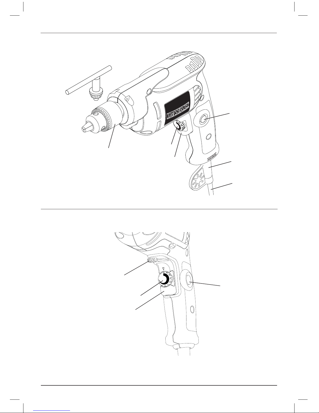
Figure 1
Figure 2
1
d
a
b
e
f
b
c
a
g
g
Page 4
2
Figure 3
Figure 4
Page 5
E NGLISH
3
VARIABLE SPEED REVERSIBLE DRILL
DWD012
Congratulations!
You have chosen a DEWALT tool. Years of
experience, thorough product development and
innovation make D
EWALT one of the most reliable
partners for professional power tool users.
Technical data
DWD012
Voltage
V
Power input
W
No load speed
min
-1
Maximum drilling range
steel/wood
mm
Chuck spindle
thread size
UNF
Maximum chuck
capacity
mm
Weight
kg
Fuses:
220-240 V tools
115 V tools
10 Amperes, mains
13 Amperes, mains
Definitions: Safety Guidelines
The definitions below describe the level of severity
for each signal word. Please read the manual and
pay attention to these symbols.
DANGER: Indicates an imminently
hazardous situation which, if not avoided,
will result in death or serious injury .
WARNING: Indicates a potentially
hazardous situation which, if not
avoided, could result in death or
serious injury .
CAUTION: Indicates a potentially
hazardous situation which, if not
avoided, may result in minor or
moderate injury .
CAUTION: Used without the safety alert
symbol indicates a potentially hazardous
situation which, if not avoided, may
result in property damage .
Denotes risk of electric shock.
Denotes risk of fire.
A9 B1
220
380
0-2,600
10/20
1/2"x20
10
1.2 1.2
220-240
380
0-2,600
10/20
1/2"x20
10
WARNING: To reduce the risk of injury,
read the instruction manual.
General Power Tool Safety Warnings
WARNING! Read all safety warnings
and instructions Failure to follow the
warnings and instructions may result in
electric shock, fire and/or serious injury.
SAVE ALL WARNINGS AND INSTRUCTIONS
FOR FUTURE REFERENCE
The term “power tool” in the warnings refers
to your mains-operated (corded) power tool or
battery-operated (cordless) power tool.
1) WORK AREA SAFETY
a) Keep work area clean and well lit.
Cluttered or dark areas invite accidents.
b) Do not operate power tools in explosive
atmospheres, such as in the presence of
flammable liquids, gases or dust. Power
tools create sparks which may ignite the dust
or fumes.
c) Keep children and bystanders away while
operating a power tool. Distractions can
cause you to lose control.
Page 6

ENGLISH
4
2) ELECTRICAL SAFETY
a) Power tool plugs must match the outlet.
Never modify the plug in any way. Do
not use any adapter plugs with earthed
(grounded) power tools. Unmodified plugs
and matching outlets will reduce risk of
electric shock.
b) Avoid body contact with earthed or
grounded surfaces such as pipes,
radiators, ranges and refrigerators. There
is an increased risk of electric shock if your
body is earthed or grounded.
c) Do not expose power tools to rain or wet
conditions. Water entering a power tool will
increase the risk of electric shock.
d) Do not abuse the cord. Never use the
cord for carrying, pulling or unplugging
the power tool. Keep cord away from
heat, oil, sharp edges or moving parts.
Damaged or entangled cords increase the
risk of electric shock.
e) When operating a power tool outdoors,
use an extension cord suitable for outdoor
use. Use of a cord suitable for outdoor use
reduces the risk of electric shock.
f) If operating a power tool in a damp
location is unavoidable, use a residual
current device (RCD) protected supply.
Use of an RCD reduces the risk of electric
shock.
3) PERSONAL SAFETY
a) Stay alert, watch what you are doing and
use common sense when operating a
power tool. Do not use a power tool while
you are tired or under the influence of
drugs, alcohol or medication. A moment of
inattention while operating power tools may
result in serious personal injury.
b) Use personal protective equipment.
Always wear eye protection. Protective
equipment such as dust mask, non-skid
safety shoes, hard hat, or hearing protection
used for appropriate conditions will reduce
personal injuries.
c) Prevent unintentional starting. Ensure
the switch is in the off position before
connecting to power source and/or
battery pack, picking up or carrying the
tool. Carrying power tools with your finger
on the switch or energising power tools that
have the switch on invites accidents.
d) Remove any adjusting key or wrench
before turning the power tool on. A
wrench or a key left attached to a rotating
part of the power tool may result in personal
injury.
e) Do not overreach. Keep proper
footing and balance at all times. This
enables better control of the power tool in
unexpected situations.
f) Dress properly. Do not wear loose
clothing or jewellery. Keep your hair,
clothing and gloves away from moving
parts. Loose clothes, jewellery or long hair
can be caught in moving parts.
g) If devices are provided for the connection
of dust extraction and collection facilities,
ensure these are connected and properly
used. Use of dust collection
can reduce
dust-related hazards.
4) POWER TOOL USE AND CARE
a) Do not force the power tool. Use the
correct power tool for your application.
The correct power tool will do the job
better and safer at the rate for which it
was designed.
b) Do not use the power tool if the switch
does not turn it on and off. Any power
tool that cannot be controlled with the switch
is dangerous and must be repaired.
c) Disconnect the plug from the power
source and/or the battery pack from
the power tool before making any
adjustments, changing accessories, or
storing power tools. Such preventive safety
measures reduce the risk of starting the
power tool accidentally.
d) Store idle power tools out
of the reach
of children and do not allow persons
unfamiliar with the power tool or these
instructions to operate the power tool.
Power tools are dangerous in the hands of
untrained users.
e) Maintain power tools. Check for
misalignment or binding of moving parts,
breakage of parts and any other condition
that may affect the power tool’s operation.
If damaged, have the power tool repaired
before use. Many accidents are caused by
poorly maintained power tools.
f) Keep cutting tools sharp and clean.
Properly maintained cutting tools with sharp
cutting edges are less likely to bind and are
easier to control.
g) Use the power tool, accessories and
tool bits etc., in accordance with these
instructions taking into account the
working conditions and the work to
be performed. Use of the power tool for
operations different from those intended
could result in a hazardous situation.
Page 7

E NGLISH
5) SERVICE
a) Have your power tool serviced by a
qualified repair person using only identical
replacement parts. This will ensure that the
safety of the power tool is maintained.
Additional Specific Safety Rules
for Drills
power tool by insulated gripping
surfaces only, when performing an
operation where the cutting accessory
may contact hidden wiring or its own
cord. Cutting accessory contacting a “live”
wire may make exposed metal parts of the
power tool “live” and shock the operator.
clamps or other practical way to
secure and support the workpiece to a
stable platform. Holding the work by hand
or against your body is unstable and may
lead to loss of control.
safety goggles or other eye
protection. Drilling operations cause chips to
fly. Flying particles can cause permanent eye
damage.
and tools get hot during operation.
Wear gloves when touching them.
handles dry, clean, free from oil and
grease. it is recommended to use rubbe
r
gloves. This will enable better control o
f the
tool.
Residual Risks
In spite of the application of the relevant safety
regulations and the implementation of safety
devices, certain residual risks cannot be avoided.
These are:
– Impairment of hearing
– Risk of personal injury due flying particles.
– Risk of burns due to accessories becoming hot
during operation.
– Risk of personal injury due to prolonged use.
Hold
Use
Wear
Bits
Keep
Markings on tool
The following pictograms are shown on the tool:
Read instruction manual
before use.
DATE CODE POSITION
Date Code, which also includes the year of
manufacture, is printed into the housing surface.
Example:
2008 XX XX
Year of Manufacture
5
Package Contents
The package contains:
1 Drill
1 Chuck key
1 Instruction manual
for damage to the tool, parts or
accessories which may have occurred during
transport.
the time to thoroughly read and
understand this manual prior to operation.
Description (fig. 1)
WARNING: Never modify the power
tool or any part of it. Damage or
personal injury could result.
a. Variable speed trigger switch
b. Lock-on button
c. Forward/reverse lever
d. Chuck
e. Cord protector
f. Cord set
g. Speed dial
Check
Take
INTENDED USE
These heavy-duty V.S.R. drills are designed for
professional drilling.
DO NOT use under wet conditions or in presence of
flammable liquids or gases.
These heavy-duty drills are professional power tools.
DO NOT let children come into contact with the
tool. Supervision is required when inexperienced
operators use this tool.
Page 8

E NGLISH
6
Electrical Safety
The electric motor has been designed for one
voltage only. Always check that the power supply
corresponds to the voltage on the rating plate.
Your DEWALT power tool is double
insulated in accordance with EN 60745;
therefore no earth wire is required.
If the supply cord is damaged, it must be replaced
by a specially prepared cord available through the
D
EWALT service organization.
WARNING: NEVER use a light socket.
NEVER connect the live (L) or
neutral (N) wires to the earth
pin marked E or
.
Using an Extension Cable
An extension cord should not be used unless
absolutely necessary. Use an approved extension
cable suitable for the power input of your charger
(see technical data). The minimum conductor size is
1 mm
2
; the maximum length is 30 m.
Also refer to the table below.
Conductor size (mm
2
) Cable rating (Amperes)
0.75 6
1.00 10
1.50 15
2.50 20
4.00 25
Cable length (m)
7.5 15 25 30 45 60
Voltage Amperes Cable rating (Amperes)
220-240 0 – 2.0 6 6 6 6 6 6
2.1 – 3.4 6 6 6 6 6 6
3.5 – 5.0 6 6 6 6 10 15
5.1 – 7.0 10 10 10 10 15 15
7.1 – 12.0 15 15 15 15 20 20
12.1 – 20.0 20 20 20 20 25 –
115 0 – 2.0 6 6 6 6 6 10
2.1 – 3.4 6 6 6 6 15 15
3.5 – 5.0 6 6 10 15 20 20
5.1 – 7.0 10 10 15 20 20 25
7.1 – 12.0 15 15 20 25 25
12.1 – 20.0 20 20 25 –
–
––
When using a cable reel, always unwind the cable
completely.
ASSEMBLY AND ADJUSTMENTS
WARNING: To reduce the risk of
injury, turn unit off and disconnect
machine from power source before
installing and removing accessories,
before adjusting or changing set-ups
or when making repairs. Be sure the
trigger switch is in the OFF position. An
accidental start-up can cause injury.
OPERATION
Instructions for Use
WARNING: Always observe the safety
instructions and applicable regulations.
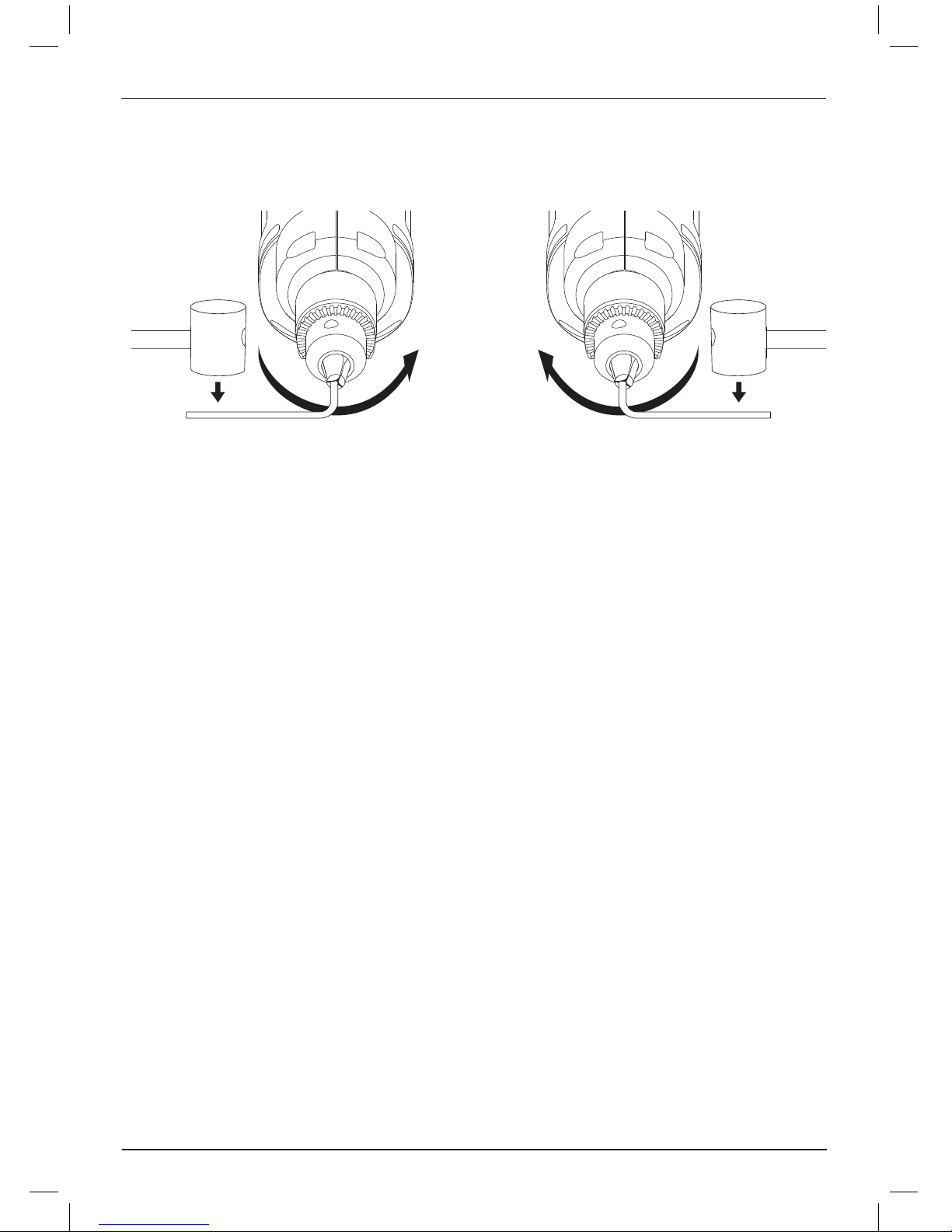
Switches (fig. 1, 2)
To start the drill, depress the trigger switch; to stop
the drill, release the trigger.
A variable speed trigger switch (a) permits speed
control—the farther the trigger is depressed, the
higher the speed of the drill.
For continuous operation, press and hold the
variable speed switch, press the lock-on button (b),
then release the switch.
NOTE:
Use lower speeds for starting holes without
a center punch, drilling in metal or plastics, driving
screws or drilling ceramics. Higher speeds are better
for drilling wood and composition boards and using
abrasive and polishing accessories.
The forward/reverse lever (c) is used for withdrawing
bits from tight holes and removing screws. It is
located above the trigger switch. To reverse the
motor, release the trigger switch FIRST and then
push the lever to the right. After any reversing
operations, re
turn lever to forward position.
To stop continuous operation, press the switch
briefly and release it. Always switch the tool off when
work is finished and before unplugging.
Drilling
WARNING: To reduce the risk of
personal injury, ALWAYS ensure
workpiece is anchored or clamped
firmly. If drilling thin material, use a wood
“back-up” block to prevent damage to
the material.
Based on the different applications, turn around the
speed dial(g) to control the maximum speed.
Page 9

E NGLISH
1. Use sharp drill bits only. For WOOD, use twist
drill bits, spade bits, power auger bits, or hole
saws. For METAL, use steel twist drill bits or
hole saws.
2. Always apply pressure in a straight line with the
bit. Use enough pressure to keep drill biting, but
do not push hard enough to stall the motor or
deflect the bit.
3. Hold tool firmly with both hands to control the
twisting action of the drill.
4. IF DRILL STALLS, it is usually because
it is being overloaded or improperly used.
RELEASE TRIGGER IMMEDIATELY, remove
drill bit from work, and determine cause of
stalling. DO NOT CLICK TRIGGER ON
AND OFF IN AN ATTEMPT TO START A
STALLED DRILL — THIS CAN DAMAGE
THE DRILL.
5. To minimize stalling or breaking through the
material, reduce pressure on drill and ease the
bit through the last fractional part of the hole.
6. Keep the motor running when pulling the bit
back out of a drilled hole. This will help prevent
jamming.
7. With variable speed drills there is no need to
center punch the point to be drilled. Use a
slow speed to start the hole and accelerate by
squeezing the trigger harder when the hole is
deep enough to drill without the bit skipping
out.
DRILLING IN METAL
Start drilling with slow speed and increase to full
power while applying firm pressure on the tool.
A smooth even flow of metal chips indicates the
proper drilling rate. Use a cutting lubricant when
drilling metals. The exceptions are cast iron and
brass which should be drilled dry.
NOTE:
Large (6 mm) holes in steel can be made
easier if a pilot hole (3 mm) is drilled first.
DRILLING IN WOOD
Start drilling with slow speed and increase to full
power while applying firm pressure on the tool.
Holes in wood can be made with the same twist
drills used for metal. These bits may overheat unless
pulled out frequently to clear chips from the flutes.
Work that is apt to splinter should be backed up
with a block of wood.
7
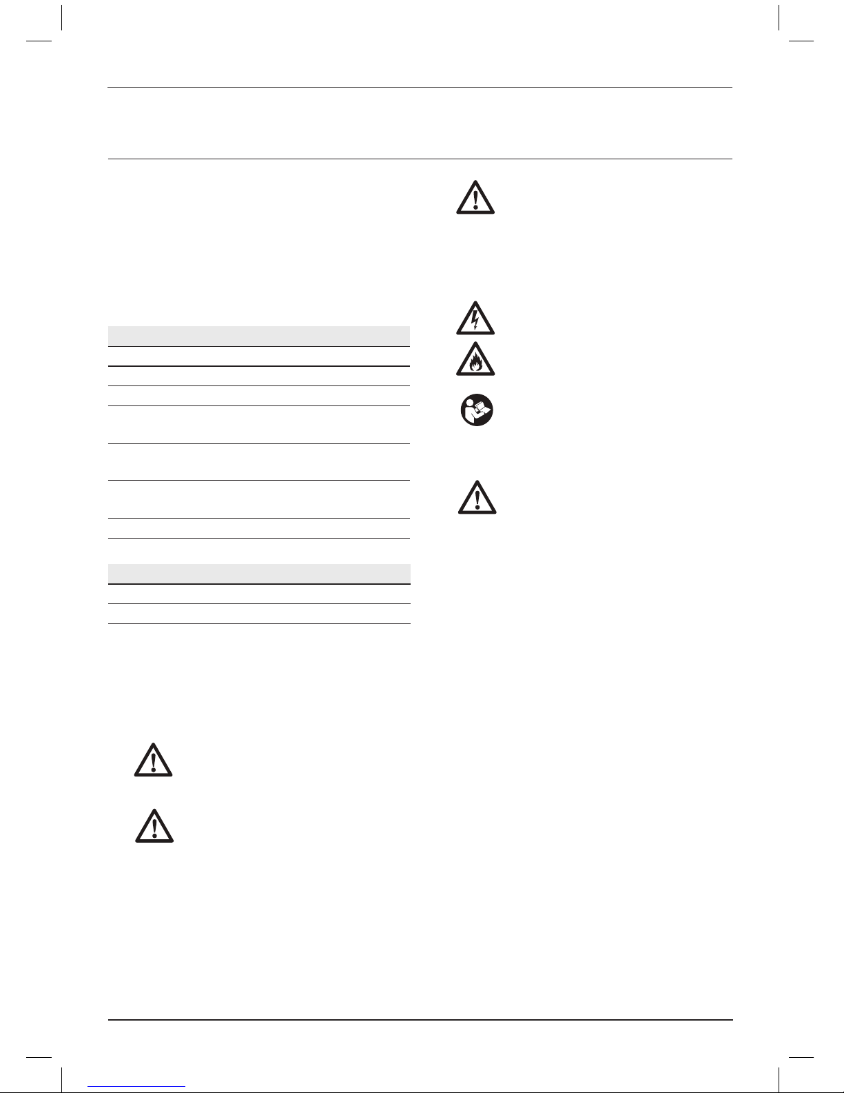
Keyed Chuck
(fig. 3, 4)
The DWD012 features a keyed chuck (d). To insert
a drill bit or other accessory, follow the steps listed
below.
1. Open the chuck jaws by turning collar by hand
and insert the shank of the bit about 3/4"
(19 mm) into chuck. Tighten the chuck collar by
hand.
2. Place chuck key in each of the three holes, and
tighten in clockwise direction. It’s important to
tighten chuck with all three holes.
To release the bit, turn the chuck counterclockwise
in just one hole, then loosen the
chuck by hand.
REMOVAL OF KEYED CHUCK (FIG. 3)
Tighten the chuck around the shorter end of a hex
key (not supplied) of 1/4" (6 mm) or greater size.
Using a soft hammer, strike the key sharply in the
counterclockwise direction when viewed from the
front of the tool. This will loosen the chuck so that it
can be removed by hand.
KEYED CHUCK INSTALLATION (FIG. 4)
Screw the chuck on by hand as far as it will go.
Insert the shorter end of a hex key (not supplied)
of 1/4" (6 mm) or greater size and strike it in the
clockwise direction with a soft hammer.
MAINTENANCE
Your DEWALT power tool has been designed to
operate over a long period of time with a minimum
of maintenance. Continuous satisfactory operation
depends upon proper tool care and regular cleaning.
WARNING: To reduce the risk of
injury, turn unit off and disconnect
machine from power source before
installing and removing accessories,
before adjusting or changing set-ups
or when making repairs. Be sure the
trigger switch is in the OFF position. An
accidental start-up can cause injury.
Page 10

E NGLISH
8
Motor Brushes
DEWALT uses an advanced brush system which
automatically stops the drill when the brushes wear
out. This prevents serious damage to the motor.
New brush assemblies are available at authorized
D
EWALT service centers. Always use identical
replacement parts.
Lubrication
Your power tool requires no additional lubrication.
Cleaning
WARNING: Blow dirt and dust out of
the main housing with dry air as often as
dirt is seen collecting in and around the
air vents. Wear approved eye protection
and approved dust mask when
performing this procedure.
WARNING: Never use solvents or
other harsh chemicals for cleaning the
non-metallic parts of the tool. These
chemicals may weaken the materials
used in these parts. Use a cloth
dampened only with water and mild
soap. Never let any liquid get inside the
tool; never immerse any part of the tool
into a liquid.
Optional Accessories
WARNING: Since accessories, other
than those offered by D
EWALT, have
not been tested with this product, use
of such accessories with this tool could
be hazardous. To reduce the risk of
injury, only D
EWALT, recommended
accessories should be used with this
product.
Consult your dealer for further information on the
appropriate accessories.
CAUTION: To reduce the risk of injury,
the following accessories should be
used only in sizes up to the maximums
shown in the table below.
MAXIMUM RECOMMENDED CAPACITIES
Drill capacity 10mm
R.P.M.
0-2,600
Bits, metal drilling
10mm
Wood, flat boring
15mm
Hole saws 20mm
Page 11

DWD012
DWD012
220-240
10
115
13
A9
220
380
0-2,600
10/20
1/2"x20
10
1.2
B1
1.2
220-240
380
0-2,600
10/20
1/2"x20
10
9
၊϶υಎ݇ᄽ
Дձᆋོ
H܅ቜӎׁ
Дԃ܅ቜӎׁ౪ࢹތhࠉઁތޙψ
֭ӎׁ߾ႌهൡܫh
Ҋ္ᄥၦНߔ࣪ĭೊႽၦಟ၉เgటเ
ࠏڀӫ֭ߔ༷࣪Ҩቜא܅hא܅
Ӊ഻֭ࠍ߅߾ಟڀӫࠏటเh
ದـތܼᆈҨቂא܅h
ٻྗ߾൘٪ෆᇍh
Iאటυಎ
א܅Ҵщ྾იҴཕhҊେၣ
ಱލ٢൜ۇሕҴhྻࢬׁ֭א܅
Ҋେ൘ႰಱލሏߘҴh໋ࣤۇሕ֭Ҵ
ތཕ֭Ҵࢄࡰചא຺ཊh
ࣦ۩Ģ
ᄏ؈ૈႽχᅾၣ༷֭
ؿ൘ႰࠏҨቜࢄ֥ᇉאgሪࠍ
ތࠏကᇟഌݥhᄥႽၣ༷֭
ࣦ۩ᇗඔნuאu܅ᆿ൯אಂ
ĩႽཔĪא܅ࠏאԅಂĩཔĪ
א܅h
Page 12

10
э૯ಮเࢬࢬׁўĭೊܽ֩gೣಫ
ތѪཙhೊݜമเࢬׁ߾ᅁࡎא
຺ཊh
Ҋ֬ࢄא܅КᄥთᇗࠏӞߔ࣪
ᇗhණ࣑א܅ࢄᅁࡎא຺ཊh
Ҋ֬ষႰאཔhҊେႰאཔϴᄖgঠ
א܅ࠏϡԣఋҴhದא܅ᄁ
ಫgႺgѐࠏᄖҎࡹhൻ෭ࠏӇ֭
אཔ߾ᅁࡎא຺ཊh
֚ᄥ߄ປ൘Ⴐא܅ĭ൘Ⴐ൩ގ߄ປ
൘Ⴐ֭ປࢬאཔh൩ގ߄ປ൘Ⴐ֭אཔࢄ
ࡰചא຺ཊh
Jಮമυಎ
Дԃࣦĭ֚Ҩቜא܅ܹሇ՞
ൡ֭ҨቜѱДԃ౪ྤhౕ༇ᄥႽொg
း༆gࣽࠏᇕٙ႓༷Ҩቜא܅h
ᄥҨቜא܅ఁ৷ٻೣ߾֥ᇉက
ᇟಮമഌݥh
൘Ⴐυಎሕᇊh൛ᇜᄣ߁ପ࣬h
υಎ
ሕᇊĭᇵೊ൩֚๐ࡹ༷֭٥ӫg٥
߉υಎཿgυಎાg๘৷٥߁ֱሕᇊେ
ࡰചಮമഌݥh
э૯ಞగhಚДܹᄥҴҴ
ԱჇܹؖ໒ᇊh൵ᆿ٪ᄥၠࢬאჿ֭
ܹഐࠏܹԱჇࢬҴେ߾
֥ᇉ຺ཊh
ᄥא܅ࢬᆵవĭମםႽנࢳᄊ
Ԅࠏϵ൵hၔᄥא܅࿐ሏࡹഐ
֭ϵ൵ࠏᄊԄ߾֥ᇉಮമഌݥh
൵Ҋ္ഭ֬ฆӑh
ሇၱ༷࢞ތമเ
ޡhᆋဪᄥၱປ౮ঋ༷େޛނׁᇍ
א܅h
ሪሕ൩֚hҊ္Դংෆၑڣࠏமփ൭
hದ֭هgၑڣތྷሸᄁᄖ
Ҏࡹhংෆၑڣgம൭ࠏӑهେ߾
ᄖҎࡹh
ೊݜ܊იஎྏሕᇊgࠪӫഩЩ৽ࢬ
Ⴐ֭ሕᇊĭᄽಚД৽ࢬຣނ൘Ⴐ
֚֬h൘Ⴐᆋོሕᇊࡰച෦ྏႌగ֭
຺ཊh
Kא܅൘Ⴐތሇၱൡལ
Ҋ္ষႰא܅ĭۼႰ൘Ⴐ൩֚
֭א܅h࿒Ⴐ൩֚֭ഩࡁصᆼ֭א
܅߾൘܅ቜႽེgۿυಎh
ೊݜܹҊେࢬࠏܹؖ܅אჿĭ
ᄽҊେ൘Ⴐۆא܅hҊେႰܹ
ধᇍ֭א܅൦຺ཊ֭щ྾࣑
ྣྱৠh
ᄥ࣑ྣಱލנࢳgۿߘۀࡹࠏሃձא
܅ᆵవĭщ྾՞אჿഐϡםҴތİ
ࠏࢄאԅޏຊאჿhᆋᇝ٥߁ྦྷնൈ
ࢄࡰചא܅ಞగ຺֭ཊh
ࢄཅᇊא܅ሃձᄥـࠫٛᆵ
ປĭѱҊ္ದҊඋ༙א܅ࠏ؛ᆋ
ོҊࢻ֭ಮҨቜא܅hא
܅ᄥ໋֭ࣤႰ߄൵ᇗ൦຺ཊ֭h
Дဩא܅hࡧҸᄖҎࡹ֭υሕ
ҽࠏሆgࡹ௭෭౮ঋތႝཡא܅
ᄖྣ֭ఋ๐ࡹhೊႽ෭ߒĭא܅
щ྾ᄥ൘Ⴐవྱઠނh࿀اൡܫႶໃ
߁Ҋ֭א܅ႌهh
Дԃౕཬ֟ڋ৮ތ౪ࢹh
Дဩނ֭
Ⴝڋ৮ౕཬಳ֭֟Ҋၦሆؿೀၦ
ᇍh
χᅾ൘Ⴐඈၣࠫս൘Ⴐ֭א܅
֭ำඁྠ္౸֭٢൜ĭቜ၄๐
ࡹތ࣑ྣ֭ቜ၄ধ൘Ⴐא܅gۀࡹ
ތ܅ֱ֭֟hא܅Ⴐቜଲོი
္౸Ҋڠ֭Ҩቜେ߾֥ᇉ຺ཊ౮ঋh
Lໃྱ
ࢄ֭א܅්ል၄ໃྱಮჼĭщ
྾൘Ⴐဪ֭Щࡹ࣑ྣۿߘhᆋဪಚД
ໃྱ֭א܅֭υಎྦྷh
Page 13

11
•
•
•
•
•
–
–
–
–
2008 XX XX
•
•
a.
b.
c.
d.
e.
f.
g.
Page 14

(L) (N)
E
(mm
2
)
0.75 6
1.00 10
1.50 15
2.50 20
4.00 25
7.5 15 25 30 45 60
220-240 0 – 2.0 6 6 6 6 6 6
2.1 – 3.4 6 6 6 6 6 6
3.5 – 5.0 6 6 6 6 10 15
5.1 – 7.0 10 10 10 10 15 15
7.1 – 12.0 15 15 15 15 20 20
12.1 – 20.0 20 20 20 20 25 –
115 0 – 2.0 6 6 6 6 6 10
2.1 – 3.4 6 6 6 6 15 15
3.5 – 5.0 6 6 10 15 20 20
5.1 – 7.0 10 10 15 20 20 25
7.1 – 12.0 15 15 20 25 25
12.1 – 20.0 20 20 25 –
–
––
12
Page 15

1.
2.
3.
4.
5.
6.
7.
3 4
DWD012 (d)
1.
3/4” 19
2.
1/4” 6
3
4
1/4” 6
OFF
13
ĩ6 ހĪ
ĩ3 ހĪ
Ԅ
Ԅ
Ԅ
Page 16

10
0-2,600
10
15
20
14
ᇍᄷĻϬ֬ĩිᇤĪ࠷Ⴝན܌ර
ׁᆾĻිᇤ܅၄჻౽
N020008
 Loading...