

Page 1

DEWALT Industrial Tool Company, 626 Hanover Pike, P.O. Box 158, Hampstead, MD 21074 Printed in USA (JUN97-CD-1) Form No. 385360
DW974, DW992, DW994 Copyright © 1997
385360/DW974 etc 5/2/02 11:25 AM Page 2
Page 2

INSTRUCTION MANUAL
GUIDE D’UTILISATION
MANUAL DE INSTRUCCIONES
DW974/DW992/DW994
Cordless Versa Clutch Driver/Drill
Perceuse-tournevis sans fil à embrayage positif Versa Clutch
Taladro/Destornillador Inalámbrico Versa Clutch
INSTRUCTIVO DE OPERACIÓN, CENTROS DE SERVICIO Y PÓLIZA
DE GARANTÍA. ADVERTENCIA: LÉASE ESTE INSTRUCTIVO ANTES
DE USAR EL PRODUCTO.
385360/DW974 etc 5/2/02 11:25 AM Page 3
Page 3
+
+
+
+
+ +
R
12311 0
English
Important Safety Instructions
(For all tools)
WARNING: When using electric tools, basic safety precautions
should always be followed to reduce risk of fire, electric shock, and
personal injury, including the following:
READ ALL INSTRUCTIONS
• KEEP WORK AREA CLEAN. Cluttered areas and benches invite
injuries.
• CONSIDER WORK AREA ENVIRONMENT.Don’t expose power tools
to rain. Don’t use power tools in damp or wet locations. Keep work area
well lit.
• GUARD AGAINST ELECTRIC SHOCK. Prevent body contact with
grounded surfaces; for example, pipes, radiators, ranges, and
refrigerator enclosures.
• KEEP CHILDREN AWAY. All visitors should be kept away from work
area. Do not let visitors contact tool.
• STORE IDLE TOOLS. When not in use, tools should be stored in dry,
and high or locked-up place — out of reach of children.
• DON’T FORCE TOOL. It will do the job better and safer at the rate for
which it was intended.
• USE RIGHT TOOL. Don’t force small tool or attachment to do the job
of a heavy duty tool. Don’t use tool for purpose not intended; for
example, don’t use circular saw for cutting tree limbs or logs.
• DRESS PROPERLY. Do not wear loose clothing or jewelry. They can
be caught in moving parts. Rubber gloves and non-skid footwear are
recommended when working outdoors. Wear protective hair covering
to contain long hair.
• USE SAFETY GLASSES. Also use face or dustmask if operation is
dusty.
• DON’T ABUSE CORD. Never carry tool by cord or yank it to
disconnect from receptacle. Keep cord from heat, oil, and sharp edges.
• SECURE WORK. Use clamps or a vise to hold work. It’s safer than
using your hand and it frees both hands to operate tool.
IF YOU HAVE ANY QUESTIONS OR COMMENTS ABOUT THIS
OR ANY D
EWALT TOOL, CALL US TOLL FREE AT:
1-800-4-DEWALT (1-800-433-9258)
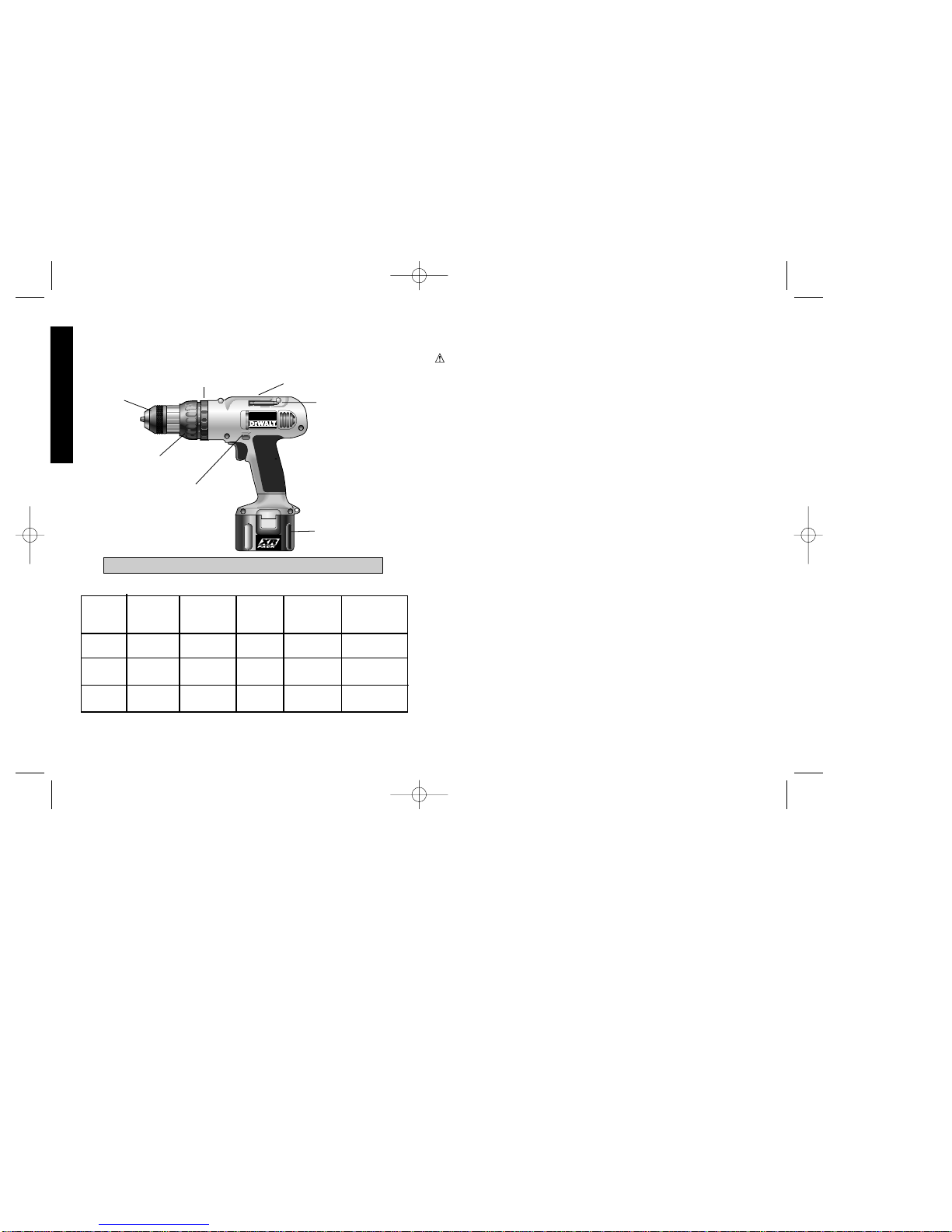
Cat # Voltage Grip Style Chuck
Capacity
Battery
Pack
RPM
DW974 12.0V
Mid
Rubber
3/8" 0-450/0-1400
DW994 14.4V
Mid
Rubber
1/2"
0-450/0-1400
Hi-Capacity
MID HANDLE RUBBER GRIP
BATTERY
PACK
BIT HOLDER
TORQUE ADJ.
COLLAR
DRIVER/DRILL SELECTOR
GEAR SHIFTER
CHUCK
FWD/REV
CONTROL
BUTTON
DW992 14.4V
Mid
Rubber
3/8"
0-450/0-1400
Hi-Capacity
Hi-Capacity
385360/DW974 etc 5/2/02 11:25 AM Page 4
Page 4

1
English
• DON’T OVERREACH. Keep proper footing and balance at all times.
• MAINTAIN TOOLS WITH CARE. Keep tools sharp and clean for
better and safe performance. Follow instructions for lubricating and
changing accessories. Keep handles dry, clean, and free from oil and
grease.
• DISCONNECT OR LOCK OFF TOOLS when not in use, before
servicing, and when changing accessories, such as blades, bits,
cutters.
• REMOVE ADJUSTING KEY AND WRENCH. Form habit of checking
to see that key and adjusting wrench is removed from tool before
turning it on.
• AVOID UNINTENTIONAL STARTING. Don’t carry tool with finger on
the switch. Be sure the switch is off when charging.
• STAY ALERT. Watch what you are doing. Use common sense. Do
not operate tool when you are tired.
• CHECK DAMAGED PARTS.Before further use of the tool, a guard or
other part that is damaged should be carefully checked to determine
that it will operate properly and perform its intended function. Check for
alignment of moving parts, binding of moving parts, breakage of parts,
mounting, and any other conditions that may affect its operation. A
guard or other part that is damaged should be properly repaired or
replaced by an authorized service center unless otherwise indicated
elsewhere in this instruction manual. Have defective switches replaced
by authorized service center. Do not use tool if switch does not turn it
on and off.
• DO NOT OPERATE portable electric tools near flammable liquids or in
gaseous or explosive atmospheres. Motors in these tools normally
spark, and the sparks might ignite fumes.
• When driving into walls, floors or wherever live electrical wires may be
encountered, DO NOT TOUCH ANY METAL PARTS OF THE TOOL!
Hold the tool only by the insulated grasping surfaces to prevent electric
shock if you drive into a live wire.
SAVE THESE INSTRUCTIONS
FOR FUTURE USE
Important Safety Instructions for Battery
Chargers
• This manual contains important safety and operating instructions.
• Before using charger, read all instructions and cautionary markings on
(1) charger, (2) battery pack, and (3) product using battery pack.
DANGER: 120 volts present at charging terminals. Do not probe with
conductive objects. Danger of electric shock or electrocution.
DANGER: If battery pack case is cracked or damaged, do not insert
into charger. Danger of electric shock or electrocution.
• The charger and battery pack are specifically designed to work
together. DO NOT attempt to charge the battery pack with any
chargers other than the ones in this manual.
• Do not expose charger to rain or snow.
• These chargers are not intended for any uses other than charging
D
EWalt rechargeable batteries. Any other uses may result in risk of fire,
electric shock or electrocution.
• To reduce risk of damage to electric plug and cord, pull by plug rather
than cord when disconnecting charger.
• Make sure cord is located so that it will not be stepped on, tripped over,
or otherwise subjected to damage or stress.
• An extension cord should not be used unless absolutely necessary.
Use of improper extension cord could result in risk of fire, electric
shock, or electrocution.
• An extension cord must have adequate wire size (AWG or American
Wire Gauge) for safety. The smaller the gauge number of the wire, the
greater the capacity of the cable, that is 16 gauge has more capacity
than 18 gauge. When using more than one extension to make up the
total length, be sure each individual extension contains at least the
minimum wire size.
385360/DW974 etc 5/2/02 11:25 AM Page 1
Page 5

Important Safety Instructions for Battery
Packs
The battery pack is not fully charged out of the carton! First read the
safety instructions below. Then follow charging notes and
procedures.
READ ALL INSTRUCTIONS.
• Do not incinerate the battery pack even if it is severely damaged or is
completely worn out.The battery pack can explode in a fire.
• A small leakage of liquid from the battery pack cells may occur under
extreme usage or temperature conditions. This does not indicate a
failure. However, if the outer seal is broken and this leakage gets on
your skin:
a. Wash quickly with soap and water.
b. Neutralize with a mild acid such as lemon juice or vinegar.
c. If battery liquid gets into your eyes, flush them with clean water for
a minimum of 10 minutes and seek immediate medical attention.
(Medical note: The liquid is 25-35% solution of potassium hydroxide.)
• Never attempt to open the battery pack for any reason. If the plastic
housing of the battery pack breaks or cracks, immediately discontinue
use and do not recharge.
• Do not carry extra battery packs in aprons, pockets, or tool boxes along
with other metal objects. Battery pack could be short circuited causing
damage to the battery pack and possibly causing severe burns or fire.
• Charge the battery packs only in D
EWalt chargers.
• NOTE: Review and observe all of the “Important Charging Notes” in
the charger instruction section of this manual.
• NOTE: The batteries in your battery pack are the nickel–cadmium
type. Cadmium is considered to be a toxic material by the
Environmental Protection Agency. Before disposing of damaged or
worn out Nickel–Cadmium battery packs, check with your state
Environmental Protection Agency to find out about special restrictions
on the disposal of these battery packs or return them to a D
EWALT
certified service center for recycling.
2
Recommended Minimum AWG Size for Extension Cords
Total Extension Cord Length (feet)
25 50 75 100 125 150 175
Wire Gauge
18 18 16 16 14 14 12
• The charger is ventilated through slots in the top and the bottom of the
housing. Do not place any object on top of charger or place the charger
on a soft surface that might block the ventilation slots and result in
excessive internal heat. Place the charger in a position away from any
heat source.
• Do not operate charger with damaged cord or plug — have them
replaced immediately.
• Do not operate charger if it has received a sharp blow, been dropped,
or otherwise damaged in any way; take it to an authorized service
center.
• Do not disassemble charger; take it to an authorized service center
when service or repair is required. Incorrect reassembly may result in
a risk of electric shock, electrocution or fire.
• To reduce risk of electric shock, unplug charger from outlet before
attempting any cleaning. Removing the battery pack will not reduce
this risk.
• NEVER attempt to connect 2 chargers together.
• DO NOT store or use the tool and battery pack in locations where the
temperature may reach or exceed 105°F (such as outside sheds or
metal buildings in summer).
• The charger is designed to operate on standard household electrical
power (120 Volts). Do not attempt to use it on any other voltage!
English
385360/DW974 etc 5/2/02 11:25 AM Page 2
Page 6
Battery Packs
Your tool uses a 12.0 Volt or a 14.4 Volt DEWALT battery pack. When
ordering replacement battery packs, be sure to include catalog
number and voltage: (12.0 Volt-DW9071) (14.4 Volt-DW9091 or
DW9092). XR PACK™ Extended Run-Time battery packs deliver
25% more run-time than standard battery packs. NOTE: Y our tool will
accept either standard or Extended Run Time battery packs.
However, be sure to select proper voltage.
3
English
• CHARGING
• CHARGED
• DELAY
D
W
9
1
1
5
D
A
N
G
E
R
:
W
A
R
N
IN
G
:
15 M
INUTE CHARGER
FLASHING
ON
FAST FLASH•DEFECTIVE PACK
ON
9
.0
v
E
X
T
E
N
D
E
D
R
U
N
T
I
M
E
1
2
.0
v
E
X
T
E
N
D
E
D
R
U
N
T
I
M
E
DW9115
D
A
N
G
E
R
:
W
A
R
N
IN
G
:
R
R
R
R
DW9115
15 MINUTE
CHARGER
DW9104,
DW9106 1 HOUR
CHARGERS
•
C
H
A
R
G
I
N
G
•
C
H
A
R
G
E
D
•
D
E
L
A
Y
1
5
M
I
N
U
T
E
C
H
A
R
G
E
R
F
L
A
S
H
I
N
G
O
N
F
A
S
T
F
L
A
S
H
•
D
E
F
E
C
T
I
V
E
P
A
C
K
O
N
D
W
9
1
1
5
DANGER:
WARNING:
R
FIG. 1
DW9107
1 HOUR CHARGER
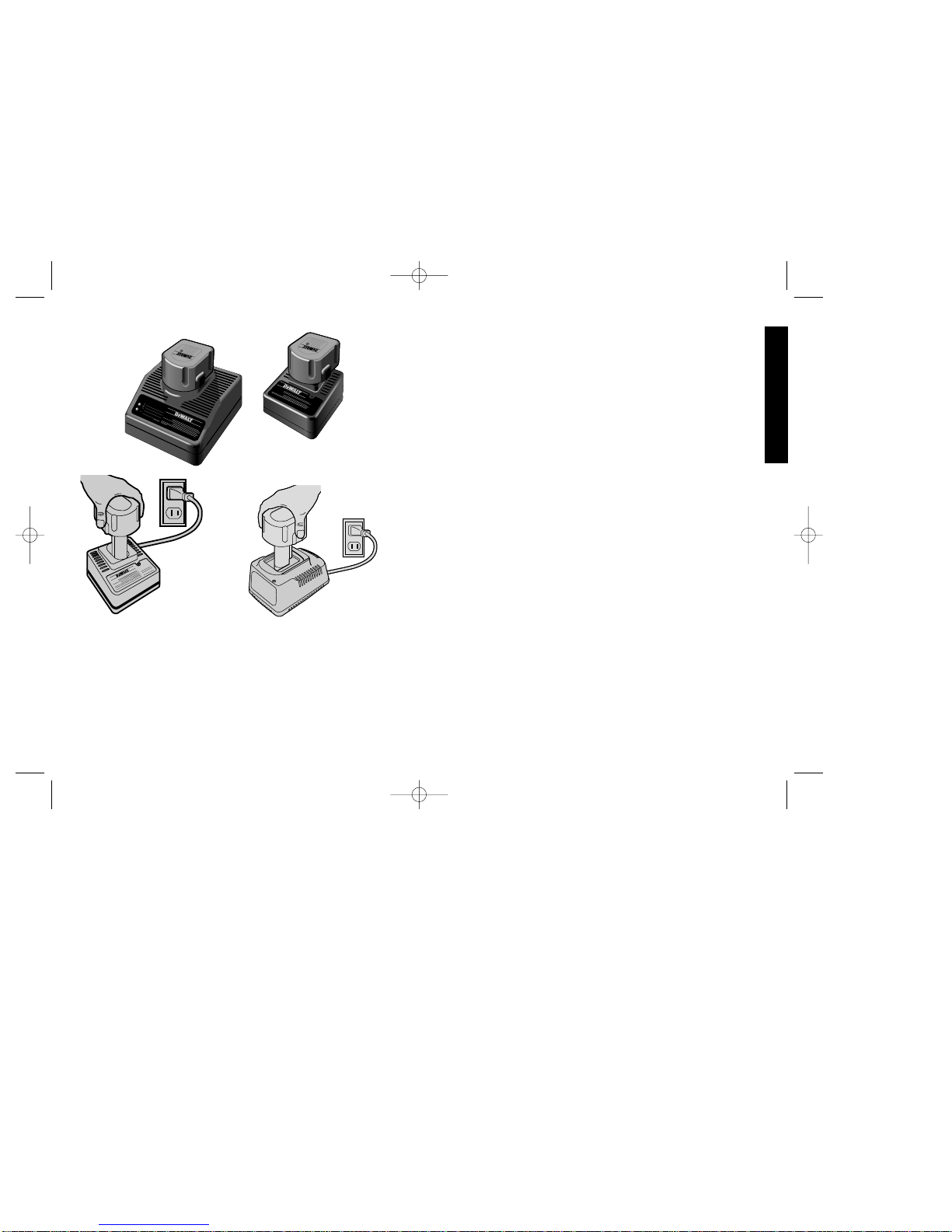
Chargers DW9104, DW9106, DW9107,
DW9115
Your battery can be charged in the DW9104, DW9106, DW9107(1
Hour Chargers),or the DW9115(15 Minute Charger) Be sure to read
all safety instructions before using your charger.
Charging Procedure
These chargers require no adjustment and are designed to be as
easy as possible to operate. Simply place your battery pack into the
receptacle of a plugged in charger (FIG.1) and it will automatically
charge the pack.
DW9104/DW9106/DW9107 (1 HOUR CHARGERS)
1. Plug the charger into an appropriate AC power outlet.
2. Insert the battery pack into the charger, as shown in FIG.1,
making sure the pack is fully seated in the charger. The red
(charging) light will blink continuously indicating that the charging
process has started.
3. The battery pack will be fully charged in about 1 hour. The
completion of charge will be indicated by the red light remaining
ON continuously. The pack is fully charged and may be used at
this time or left in the charger.
DW9115 (15 MINUTE CHARGER)
1. Plug the charger into an appropriate AC power outlet. The charger
will beep twice, the red light will blink and go off.
2. Insert the battery pack into the charger, as shown in FIG. 1,
making sure the pack is fully seated in the charger. The red light
will blink and the charger will beep once indicating the charging
process has started.
3. The battery pack will be fully charged in less than 15 minutes
under most conditions. This will be indicated by the red light
remaining ON and 3 beeps. The pack is fully charged and may
be used at this time or left in the charger.
385360/DW974 etc 5/2/02 11:25 AM Page 3
Page 7
Weak Battery Packs: (DW9115). The charger can also detect a
weak battery. Such batteries are still usable but should not be
expected to perform as much work. In such cases, about 10 seconds
after battery insertion, the charger will beep rapidly 8 times to indicate
a weak battery condition. The charger will then go on to charge the
battery to the highest capacity possible.
Leaving the battery pack in the charger: The battery pack can be
removed at any time during these charge cycles, but will only be
fully charged if the red light is continuously ON. The charger and
battery pack can be left connected with the red light glowing
indefinitely. The charger will keep the battery pack fresh and fully
charged. A battery pack will slowly lose its charge when kept out of
the charger. If the battery pack has not been kept on maintenance
charge, it may need to be recharged before use. A battery pack may
also slowly lose its charge if left in a charger that is not plugged into
an appropriate AC source.
Trouble Indicators: These chargers are designed to detect certain
problems that can arise with battery packs which would be indicated
by the red light flashing at a fast rate (and continuous beeping for
DW9115). If this occurs, re-insert battery pack. If problem persists, try
a different battery pack to determine if the charger is OK. If the new
pack charges correctly, then the original pack is defective and should
be returned to a service center for recycling. If the new battery pack
elicits the same trouble indication as the original, have charger tested
at an authorized service center.
Equalization Mode (DW9107 only)
When the red light remains ON, the charger has switched to its
"equalize charge" mode which lasts approximately 6 hours, after
which the charger will switch to "maintenance charge" mode.
PROBLEM POWER LINE (DW9107)
When these chargers are used with some portable power sources
such as generators or sources that convert DC to AC, the chargers
may temporarily suspend operation, flashing the red light with two
fast blinks followed by a pause. This indicates the power source is
out of limits.
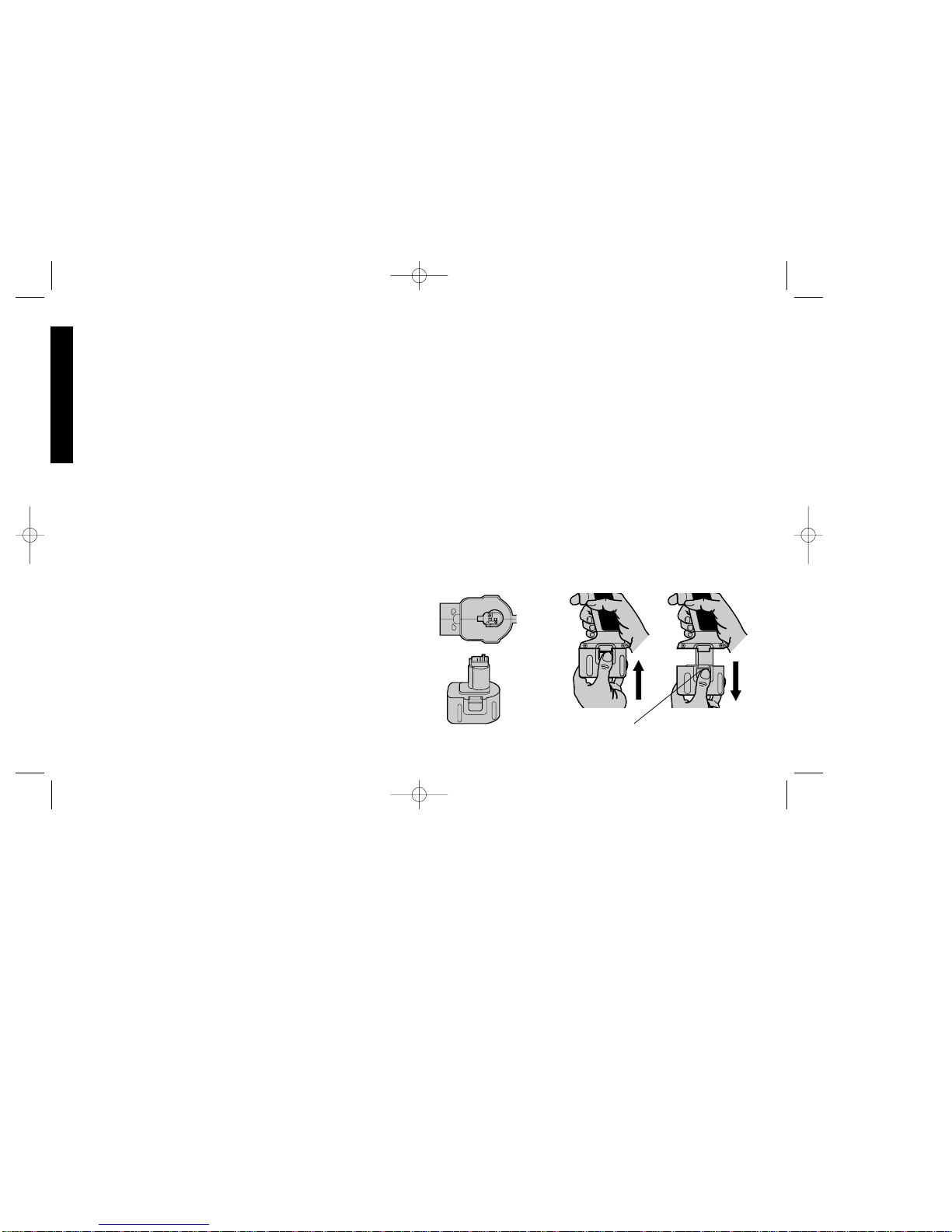
Installing and Removing the Battery Pack
NOTE: Make sure your battery pack is fully charged.
To install the battery packinto the tool handle, align the base of the
tool with the notch inside the tool’s handle (FIG.2) and slide the
battery pack firmly into the handle until you hear the lock snap into
place as shown in FIG. 3. To remove the battery pack from the tool,
press the release buttons and firmly pull the battery pack out of the
tool handle. Insert it into the charger as described in the charger
section of this manual.
Important Charging Notes
1. Longest life and best performance can be obtained if the battery
pack is charged when the air temperature is between 65°F and
75°F (18°- 24°C). DO NOT charge the battery pack in an air
temperature below +40°F(+4.5°C), or above +105°F (+40.5°C).
This is important and will prevent serious damage to the battery
pack.
2. The charger and battery pack may become warm to touch while
charging. This is a normal condition, and does not indicate a
problem.
4
English
RELEASE BUTTON
FIG. 2
FIG. 3
385360/DW974 etc 5/2/02 11:25 AM Page 4
Page 8
5
English
3. (DW9115) This charger has an internal temperature limit that,
when exceeded, will temporarily stop the full charge current. This
is indicated by the yellow light being ON. The normal charge cycle
will resume when the temperature falls below the preset limit and
will be indicated by the yellow light turning OFF. The charge time
may be extended beyond the normal 15 minutes. Use the charger
in normal room temperatures whenever possible. To prevent
overheating, do not cover the charger and do not charge battery
packs in direct sunlight or near heat sources.
4. If the battery pack does not charge properly — (1) Check current
at receptacle by plugging in a lamp or other appliance, (2) Check
to see if receptacle is connected to a light switch which turns
power off when you turn out the lights. (3) Move charger and
battery pack to a location where the surrounding air temperature
is approximately 65°F - 75°F (18°- 24°C). (4) If charging problems
persist, take or send the tool, battery pack and charger to your
local service center.
5. The battery pack should be recharged when it fails to produce
sufficient power on jobs which were easily done previously. DO
NOT CONTINUE to use under these conditions. Follow the
charging procedure. You may also charge a partially used pack
whenever you desire with no adverse affect on the battery pack.
6. Under certain conditions, with the charger plugged in to the power
supply, the exposed charging contacts inside the charger can be
shorted by foreign material. Foreign materials of a conductive
nature such as, but not limited to, steel wool, aluminum foil, or any
buildup of metallic particles should be kept away from charger
cavities. Always unplug the charger from the power supply when
there is no battery pack in the cavity. Unplug charger before
attempting to clean.
7. Do not freeze or immerse charger in water or any other liquid.
8. WARNING:Don't allow any liquid to get inside charger. Electric
shock may result. T o facilitate the cooling of the battery pack after
use, avoid placing the charger or battery pack in a warm
environment such as in a metal shed, or an uninsulated trailer.
9. CAUTION: Never attempt to open the battery pack for any
reason. If the plastic housing of the battery pack breaks or cracks,
return to a service center for recycling.
Important!
This product is not user servicable. There are no user servicable
parts inside the charger. Servicing at an authorized service center is
required to avoid damage to static sensitive internal components.
READ ALL OF THE INSTRUCTIONS IN THE BATTER Y CHARGER
SECTION OF THIS MANUAL BEFORE ATTEMPTING TO
CHARGE THE BATTERY PACK FOR YOUR TOOL.
Always use correct battery pack (pack supplied with tool or
replacement pack exactly like it.) Never install any other battery pack.
It will ruin your tool and may create a hazardous condition.
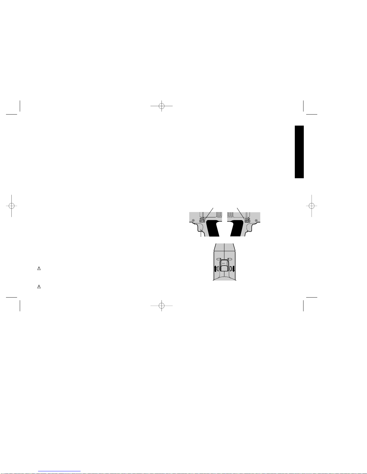
Locked
Depress for Reverse
Depress for Forward
FIG. 4
TRIGGER
SWITCH
385360/DW974 etc 5/2/02 11:25 AM Page 5
Page 9
Variable Speed Switch
To turn the tool on, squeeze the trigger switch. To turn the tool off,
release the trigger switch. Your tool is equipped with a brake. The
chuck will stop as soon as the trigger switch is fully released.
The variable speed switch enables you to select the best speed for
a particular application. The farther you squeeze the trigger, the
faster the tool will operate. Use lower speeds for starting holes
without a centerpunch, drilling in metals or plastics, driving screws
and drilling ceramics, or in any application requiring high torque.
Higher speeds are better for drilling in wood, wood compositions
and for using abrasive and polishing accessories. For maximum tool
life, use variable speed only for starting holes or fasteners.
NOTE: Continuous use in variable speed range is not recommended.
It may damage the switch and should be avoided.
Forward/Reverse Control Button
(FIG. 4) A forward/reverse control button determines the direction of
the tool and also serves as a lock off button. To select forward
rotation, release the trigger switch and depress the forward/reverse
control button on the right side of the tool.To select reverse, depress
the forward/reverse control button on the left side of the tool. The
center position of the control button locks the tool in the off position.
When changing the position of the control button, be sure the trigger
is released. NOTE: The first time the tool is run after changing the
direction of rotation, you may hear a click on start up. This is normal
and does not indicate a problem.
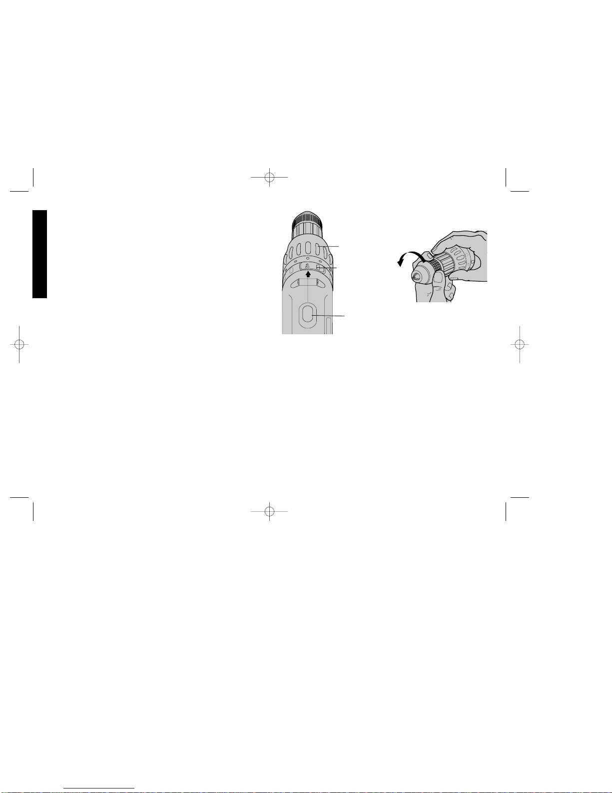
Torque Adjustment Collar
The Versa Clutch feature of your Driver/Drill is an adjustable torque
screwdriver mechanism for driving and removing a wide array of
fastener shapes and sizes. The Versa Clutch allows you to
instantaneously regulate the torque, based on the force applied.
Circling the collar are numbers ranging from 0 to 11. These numbers
(and half numbers designated by dots on the collar) are used to set
the clutch to deliver a torque range. The higher the number on the
6
English
4
3
2
5
collar, the higher the torque and the larger the fastener which can be
driven. T o select any of the numbers, rotate until the desired number
aligns with the selector, shown in FIG. 5.
Dual Range Gearing
The dual range feature of your Driver/Drill allows you to shift gears for
greater versatility. To select the low speed, high torque setting
(position 1), turn the tool off and permit to stop. Push the button
forward towards the chuck, as shown in FIG. 5. To select the high
speed, low torque setting (position 2), turn the tool off and permit to
stop. Slide the gear shifter back (away from chuck).
NOTE: Do not change gears when the tool is running. If you are
having trouble changing gears, make sure that the dual range gear
button is either completely pushed forward or completely pushed
back.
Clutch Lock
To lock the clutch for drilling operations, simply move the Driver/Drill
3
2
4
FIG. 5
TORQUE
ADJUSTMENT
COLLAR
DUAL RANGE
GEAR
SHIFTER
DRIVER/DRILL
SELECTOR
FIG. 6
385360/DW974 etc 5/2/02 11:25 AM Page 6
Page 10
7
English
selector to the "Drill" position as described under “Operation as a
Drill.” (You may shift the Driver/Drill selector regardless of the
adjustment collar setting.)
Since the adjustment collar and the Driver/Drill selector are distinctly
different controls, you can switch between drilling and screwdriving
without touching the adjustment collar. Once the collar is set, it
remains unchanged until you decide to change it.
Keyless Chuck
Your tool features a keyless chuck for greater convenience. To insert
a drill bit or other accessory, follow the steps listed below.
1. Lock the trigger switch in the off position as described on page 6.
2. Grasp the rear half of the chuck with one hand and use your other
hand to rotate the front half counterclockwise, as shown in FIG 6.
Rotate far enough so that the chuck opens sufficiently to accept
the desired accessory.
3. Insert the bit or other accessory about 3/4” into the chuck and
tighten securely by holding the rear half of the chuck and rotating
the front portion in the clockwise direction.
To release the accessory, repeat step 2 listed above.
WARNING: Do not attempt to tighten drill bits (or any other
accessory) by gripping the front part of the chuck and turning the tool
on. Damage to the chuck and personal injury may result. Always lock
off trigger switch when changing accessories.
Be sure to tighten chuck with two hands on both the rear sleeve and
the forward sleeve for maximum tightness.
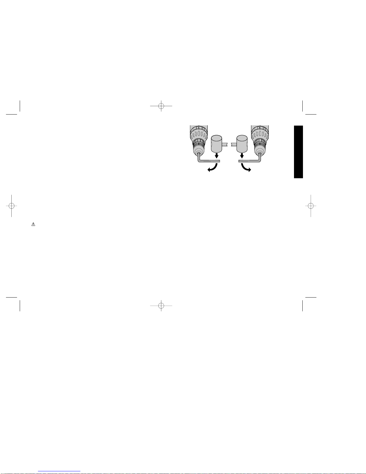
Chuck Removal
Always wear eye protection.
Turn the adjustment collar to the “drill” position and low speed gear
shifter position 1. Tighten the chuck around the shorter end of a hex
key (not supplied) of 1/4” or greater size. Using a wooden mallet or
similar object, strike the longer end in the clockwise direction, as
shown in FIG. 7. This will loosen the screw inside the chuck.
Open chuck jaws fully, insert screwdriver (or Torx tool if required) into
front of chuck between jaws to engage screw head. Remove screw
by turning clockwise (left-hand-thread). Place hex key in chuck and
tighten, as shown in FIG. 8. Using a wooden mallet or similar object,
strike key sharply in the counterclockwise direction. This will loosen
the chuck so that it can be unscrewed by hand.
Chuck Installation
Screw the chuck on by hand as far as it will go and insert screw (LH
thread). Tighten screw securely. Tighten the chuck around the shorter
end of a 1/4” or larger hex key (not supplied) strike the longer end in the
clockwise direction with a wooden mallet, as shown in FIG. 7. Tighten the
screw once again by turning in a counterclockwise direction.
Operation as a Drill
Turn the collar to the drill bit symbol. Install and tighten the desired
drill bit in the chuck. Select the desired speed/torque range using
the dual range gear shifter to match the speed and torque to the
planned operation. Follow these instructions for best results when drilling.
DRILLING
1. Use sharp drill bits only. For WOOD, use twist drill bits, spade bits,
power auger bits, or hole saws. For METAL, use high speed steel twist
drill bits or hole saws. For MASONRY, such as brick, cement, cinder
4
3
2
1
5
6
4
3
2
1
5
6
FIG. 8
FIG. 7
385360/DW974 etc 5/2/02 11:25 AM Page 7
Page 11

flow of dust indicates the proper drilling rate.
Operation as a Screwdriver
Turn the Driver/Drill selector to the symbol of a screw. Select the desired
speed/torque range using the dual range gear shifter on the top of tool to
match the speed and torque to the planned operation. Insert the desired
fastener accessory into the chuck as you would any drill bit. Make a few
practice runs in scrap or unseen areas to determine the proper position of
the clutch collar.
Pressure Activated Chuck
When in the screwdriving mode, THE CHUCK WILL NOT TURN
UNTIL PRESSURE IS APPLIED IN LINE WITH THE FASTENER.
Likewise, the chuck stops when pressure is released. This pressure
activated chuck feature improves accuracy of work and significantly
increases the rate at which screws can be driven.
Maintenance
CLEANING: With the motor running, blow dirt and dust out of all air
vents with dry air at least once a week. Wear safety glasses when
performing this. Exterior plastic parts may be cleaned with a damp
cloth and mild detergent. Although these parts are highly solvent
resistant, NEVER use solvents.
Charger Cleaning Instructions:
WARNING: Disconnect the charger from the AC outlet before
cleaning.
Dirt and grease may be removed from the exterior of the charger
using a cloth or soft non-metallic brush. Do not use water or any
cleaning solutions.
Accessories
Recommended accessories for use with your tool are available at
extra cost from your local service center.
CAUTION: The use of any non-recommended accessory may be
hazardous.
8
English
block, etc., use carbide-tipped bits.
2. Be sure the material to be drilled is anchored or clamped firmly. If
drilling thin material, use a “back-up” block to prevent damage to the
material.
3. Always apply pressure in a straight line with the bit. Use enough
pressure to keep the drill bit biting, but do not push hard enough to
stall the motor or deflect the bit.
4. Hold tool firmly to control the twisting action of the drill.
5. IF DRILL STALLS, it is usually because it is being overloaded.
RELEASE TRIGGER IMMEDIATELY, remove drill bit from work, and
determine cause of stalling. DO NOT CLICK TRIGGER OFF AND ON
IN AN ATTEMPT TO START A STALLED DRILL – THIS CAN
DAMAGE THE DRILL.
6. To minimize stalling or breaking through the material, reduce pressure
on drill and ease the bit through the last fractional part of the hole.
7. Keep the motor running when pulling the bit back out of a drilled hole.
This will help prevent jamming.
8. With variable speed drills there is no need to center punch the point to
be drilled. Use a slow speed to start the hole and accelerate by
squeezing the trigger harder when the hole is deep enough to drill
without the bit skipping out. Operate at full on after starting the bit.
Drilling in Wood
Holes in wood can be made with the same twist drills used for metal.
These bits may overheat unless pulled out frequently to clear chips from
the flutes. For larger holes, use low speed wood bits. Work that is likely to
splinter should be backed up with a block of wood.
Drilling in Metals
Use a cutting lubricant when drilling metals. The exceptions are cast iron
and brass which should be drilled dry. The cutting lubricants that work best
are sulphurized cutting oil or lard oil; bacon grease will also serve the
purpose.
Drilling Masonry
Use carbide tipped masonry bits at low speeds. Keep even force on the
drill but not so much that you crack the brittle materials. A smooth, even
385360/DW974 etc 5/2/02 11:25 AM Page 8
Page 12

If you need any assistance in locating any accessory, please contact
D
EWalt Industrial Tool Company, P.O. Box 158, 626 Hanover Pike,
Hampstead, MD 21074 or call 1-800-4-D
EWALT. (1-800-433-9258)
MAXIMUM RECOMMENDED CAPACITIES
Low Range- 1 High Range- 2
BITS, METAL DRILLING 3/8" 1/4"
WOOD, FLAT BORING 1" 5/8"
HOLE SAWS 1" 3/4"
Important
To assure product SAFETY and RELIABILITY, repairs, maintenance
and adjustment (including brush inspection and replacement) should
be performed by authorized service centers or other qualified service
organizations, always using identical replacement parts.
Full Warranty
DEWALT heavy duty industrial tools are warranted for one year from
date of purchase. We will repair, without charge, any defects due to
faulty materials or workmanship. For warranty repair information, call
1-800-4-D
E
WALT. This warranty does not apply to accessories or
damage caused where repairs have been made or attempted by
others. This warranty gives you specific legal rights and you may have
other rights which vary in certain states or provinces.
In addition to the warranty, D
EWALT tools are covered by our:
30 DAY NO RISK SATISFACTION GUARANTEE
If you are not completely satisfied with the performance of your
D
EWALTheavy duty industrial tool, simply return it to the participating
seller within 30 days for a full refund. Please return the complete unit,
transportation prepaid. Proof of purchase may be required.
9
English
385360/DW974 etc 5/2/02 11:25 AM Page 9
Page 13

Importantes mesures de sécurité
(pour tous les outils)
AVERTISSEMENT : Afin de réduire les risques d’incendie, de
secousses électriques ou de blessures lorsqu’on utilise des outils
électriques, il faut toujours respecter les mesures de sécurité
suivantes.
LIRE TOUTES LES DIRECTIVES.
• BIEN DÉGAGER LA SURFACE DE TRAVAIL. Des surfaces et
des établis encombrés peuvent être la cause de blessures.
• TENIR COMPTE DU MILIEU DE TRAVAIL. Protéger les outils
électriques de la pluie. Ne pas s’en servir dans des endroits
humides ou mouillés. Bien éclairer la surface de travail.
• SE PROTÉGER CONTRE LES SECOUSSES ÉLECTRIQUES.
Éviter tout contact avec des objets mis à la terre, comme des
tuyaux, radiateurs, cuisinières, réfrigérateurs et autres objets du
genre.
• ÉLOIGNER LES ENFANTS. Tous les visiteurs doivent être tenus
à l’écart de l’aire de travail et il faut les empêcher de toucher à
l’outil .
• RANGER LES OUTILS INUTILISÉS. Il faut ranger les outils dans
un endroit sec, situé en hauteur ou fermé à clé, hors de la portée
des enfants.
• NE JAMAIS FORCER L’OUTIL. Afin d’obtenir un rendement sûr
et efficace, utiliser l’outil à son rendement nominal.
• UTILISER L’OUTIL APPROPRIÉ. Ne jamais exiger d’un petit outil
ou d’un accessoire le rendement d’un outil de fabrication plus
robuste. Se servir de l’outil selon l’usage prévu (par exemple, ne
pas se servir d’une scie circulaire pour couper des branches
d’arbres ou des bûches).
• PORTER DES VÊTEMENTS APPROPRIÉS. Éviter de porter des
vêtements amples et des bijoux qui peuvent être happés par les
pièces en mouvement. Porter des gants de caoutchouc et des
chaussures à semelle antidérapante pour travailler à l’extérieur.
Protéger la chevelure si elle est longue.
Français
POUR TOUT RENSEIGNEMENT SUPPLÉMENTAIRE SUR CET
OUTIL OU TOUT AUTRE OUTIL D
EWALT, COMPOSER SANS
FRAIS LE NUMÉRO :
1 800 4-DEWALT (1 800 433-9258)
+
+
+
+
+ +
R
12311 0
CAOUTCHOUC AU CENTRE
ENSEMBLE
DE PILES
PORTEFORETS
COLLIER DE
RÉGLAGE DU
COUPLE
SÉLECTEUR DU
MODE DE
FONCTIONNEMENT
SÉLECTEUR DE LA
GAMME DE VITESSES
MANDRIN
INVERSEUR
DE MARCHE
DW974
12,0 V
DW992
14,4 V
DW994
14,4 V
A haute
capacité
10 mm
(3/8 po)
10 mm
(3/8 po)
13 mm
(1/2 po)
Tension Prise
Capacité
du
mandrin
Ensemble
de piles
Régime
(trs/min)
Cat. n
o
Caoutchouc
au centre
Caoutchouc
au centre
De 0 à 450
De 0 à 1 400
De 0 à 450
De 0 à 1 400
De 0 à 450
De 0 à 1 400
10
Caoutchouc
au centre
A haute
capacité
A haute
capacité
385360/DW974 etc 5/2/02 11:25 AM Page 10
Page 14

• PORTER DES LUNETTES DE SÉCURITÉ. Porter également un
masque respiratoire si le travail de coupe produit de la poussière.
• NE PAS MANIPULER LE CORDON DE FAÇON ABUSIVE. Ne
pas transporter l’outil par le cordon ni tirer sur ce dernier pour le
débrancher de la prise. Éloigner le cordon des sources de chaleur,
des flaques d’huile et des arêtes tranchantes.
• ASSUJETTIR LA PIÈCE. Immobiliser la pièce à l’aide de brides
ou d’un étau. On peut alors se servir des deux mains pour faire
fonctionner l’outil, ce qui est plus sûr.
• NE PAS DÉPASSER SA PORTÉE. Toujours demeurer dans une
position stable et garder son équilibre.
• PRENDRE SOIN DES OUTILS. Conserver les outils propres pour
qu’ils donnent un rendement supérieur et sûr. Suivre les directives
concernant la lubrification et le remplacement des accessoires.
S’assurer que les poignées sont toujours propres, sèches et libres
de toute tache d’huile ou de graisse.
• DÉBRANCHER LES OUTILS NON UTILISÉS. Respecter cette
mesure lorsqu’on ne se sert pas de l’outil, ou qu’on doit le réparer
ou en changer un accessoire (comme une lame, un foret ou un
couteau).
• ENLEVER LES CLÉS DE RÉGLAGE. Prendre l’habitude de
vérifier si les clés de réglage ont été retirées avant de faire
démarrer l’outil.
• ÉVITER LES DÉMARRAGES ACCIDENTELS. Ne pas laisser le
doigt sur l’interrupteur lorsqu’on transporte l’outil. S’assurer que
l’interrupteur est à la position hors circuit lorsqu’on branche l’outil.
• DEMEURER VIGILANT. Travailler avec vigilance et faire preuve
de bon sens. Ne pas se servir de l’outil lorsqu’on est fatigué.
• VÉRIFIER LES PIÈCES ENDOMMAGÉES. Vérifier l’alignement
et les attaches des pièces mobiles, le degré d’usure des pièces et
leur montage, ainsi que tout autre facteur susceptible de nuire au
bon fonctionnement de l’outil. Faire réparer ou remplacer tout
protecteur ou toute autre pièce endommagée dans un centre de
service autorisé, sauf si le présent guide fait mention d’un avis
11
Français
contraire. Confier le remplacement de tout interrupteur défectueux
à un centre de service autorisé. Ne jamais se servir d’un outil dont
l’interrupteur est défectueux.
• NE PAS UTILISER les outils portatifs électriques dans des
endroits où l’atmosphère contient des vapeurs combustibles ou
explosives. Les étincelles que produit le moteur en marche
pourraient enflammer ces produits.
• Lorsqu’on perce ou qu’on visse dans les murs, les planchers ou tout
autre endroit où peuvent se trouver des fils sous tension, NE PAS
TOUCHER AUX COMPOSANTS MÉTALLIQUES DE L’OUTIL. Ne le
saisir que par ses surfaces isolées afin de se protéger des secousses
électriques que provoquerait le contact de la lame avec un fil sous
tension.
CONSERVER CES MESURES.
Importantes mesures de sécurité relatives
au chargeur
• Le présent guide contient des conseils importants relatifs à la sécurité
et à l’utilisation.
• Bien lire toutes les directives et tous les avertissements qui se trouvent
sur (1) le chargeur, (2) l’ensemble de piles et (3) l’outil avant d’utiliser
le chargeur.
DANGER : Les bornes du chargeur sont sous une tension de 120 volts.
Ne pas les examiner avec un objet conducteur; cela présente des
risques de secousses électriques.
DANGER : Ne pas placer dans le chargeur un ensemble de piles
craqué ou endommagé; cela présente des risques de secousses
électriques.
• Le chargeur et l’ensemble de piles ont été conçus pour fonctionner
ensemble. NE JAMAIS tenter de charger l’ensemble de piles à l’aide
d’un chargeur autre que ceux décrits dans le présent guide.
• Protéger le chargeur de la pluie ou de la neige.
• L’utilisation du chargeur pour tout ensemble de piles autre que les
ensembles rechargeables D
EWalt comporte des risques d’incendie et
385360/DW974 etc 5/2/02 11:25 AM Page 11
Page 15

secousses électriques.
• Pour minimiser les risques de secousses électriques, débrancher le
chargeur de la prise de courant avant de le nettoyer. Le risque n’est
pas éliminé en enlevant l’ensemble de piles du chargeur.
• NE JAMAIS raccorder deux chargeurs l’un à l’autre.
• NE PAS ranger le produit dans un endroit où la température peut
atteindre 40 °C (105 °F) (comme dans une remise métallique en été).
• Le chargeur est conçu pour fonctionner sur une alimentation
domestique standard (120 volts). Ne pas essayer de s’en servir sous
toute autre tension.
Importantes mesures de sécurité relatives
aux ensembles de piles
L’ensemble de piles n’est pas complètement chargé à sa sortie de
l’usine. Lire d’abord les instructions suivantes, puis se conformer aux
directives relatives au chargement.
LIRE TOUTES LES DIRECTIVES.
• Ne pas incinérer l’ensemble de piles même s’il est très endommagé ou
complètement usé. La chaleur des flammes peut faire exploser les
piles.
• Il peut se produire une légère fuite du liquide excitateur des piles dans
des conditions d’utilisation et de chargement difficiles ou en cas de
température extrême, fuite qui ne serait pas nécessairement un signe
de panne. Toutefois, si ce liquide s’échappe par une rupture du joint
étanche du boîtier et atteint la peau, il faut :
a. laver immédiatement à l’eau et au savon;
b. neutraliser à l’aide d’un acide doux (jus de citron ou vinaigre)
c. si le liquide excitateur atteint les yeux, il faut rincer à l’eau claire
pendant au moins dix minutes et consulter immédiatement un
médecin. (Avis au médecin : le liquide excitateur est une solution
d’hydrogène de potassium à 25-35 p. 100.)
• Ne pas tenter d’ouvrir le boîtier de l’ensemble de piles. Si le boîtier en
plastique se fend ou se brise, ne plus s’en servir et ne pas le recharger.
• Ne pas transporter des ensembles de piles de rechange dans des
12
de secousses électriques.
• Pour minimiser les risques de dommages au cordon et à sa fiche,
débrancher l’appareil en tirant sur la fiche plutôt que sur le cordon.
• Veiller à ce que le cordon soit rangé de sorte qu’on ne marche pas
dessus, qu’il ne présente pas de risques de blessures, et qu’il ne soit
pas autrement sujet aux dommages et aux contraintes.
• Sauf nécessité absolue, ne jamais utiliser de cordon de rallonge.
L’utilisation d’un cordon de rallonge non conforme présente des
risques d’incendies et de secousses électriques.
• Les cordons de rallonge doivent être faits de conducteurs de calibre
approprié (AWG ou jauge américaine des fils) par mesure de sécurité.
Le numéro de calibre du fil est inversement proportionnel à la capacité
du cordon. Ainsi, un cordon de calibre 16 a une capacité supérieure à
celle d’un cordon de calibre 18. Lorsqu’il est nècessaire d’utiliser plus
d’un cordon de rallonge, veiller à ce que chaque cordon ait au moins le
calibre minimal.
CALIBRE MINIMAL RECOMMANDÉ (AWG)
POUR LES CORDONS DE RALLONGE
Longueur totale de cordon de rallonge (en mètres)
7,6 15 30 50
Calibre (AWG) du cordon
18 18 16 14
• La ventilation du chargeur se fait par les fentes sur le dessus et le
dessous de l’appareil. Ne rien déposer sur le chargeur et ne pas
déposer ce dernier sur une surface qui pourrait en bloquer les orifices
car cela risque de provoquer la surchauffe de l’appareil. Éloigner le
chargeur des sources de chaleur.
• Ne jamais se servir du chargeur lorsque le cordon ou la fiche sont
endommagés. Les remplacer immédiatement.
• Ne jamais se servir d’un chargeur qui a encaissé un coup brusque,
qui est tombé ou qui est endommagé. Le faire vérifier à un centre de
service autorisé.
• Ne jamais démonter le chargeur. N’en confier la réparation ou
l’entretien qu’à un centre de service autorisé. Le remontage non
conforme du produit comporte des risques d’incendies ou de
Français
385360/DW974 etc 5/2/02 11:25 AM Page 12
Page 16

tabliers, des poches ou des coffres à outil avec d’autres objets
métalliques. L’ensemble de piles pourrait alors être court-circuité, ce
qui l’endommagerait et présenterait des risques de brûlures
importantes ou d’incendie.
• Les ensembles de piles doivent être chargés seulement à l’aide d’un
chargeur D
EWalt.
• NOTE : Relire et respecter toutes les notes importantes relatives au
chargement qu’on retrouve dans le présent guide.
• NOTE : Les piles de l’ensemble renferment du nickel-cadmium. Le
cadmium est un produit toxique. Avant de se débarrasser d’un
ensemble de piles au nickel-cadmium, se renseigner sur les
règlements locaux à cet effet ou retourner l’ensemble de piles à un
centre de service D
EWALT autorisé pour qu’il y soit recyclé.
Ensembles de piles
L’outil nécessite un ensemble de piles DeWALT de 9,6, de 12,0 ou
de 14,4 volts. Lorsqu’on commande un ensemble de piles de
rechange, bien indiquer le numéro de modèle et la tension (9,6 volts
- DW9061) (12,0 volts - DW9071) (14,4 volts - DW9091 ou DW9092).
Les ensembles de piles XR PACK™à durée prolongée durent
25 p. 100 plus longtemps que les ensembles de piles standard.
NOTE : On peut utiliser des ensembles de piles standard ou à durée
prolongée avec l’outil. Il faut toutefois s’assurer que la tension est
appropriée.
Chargeurs, modèles DW9104, DW9106,
DW9107, et DW9115
L’ensemble de piles peut être chargé dans le chargeur DW9104 ou
DW9106 (chargeurs en une heure), ou encore dans le chargeur
DW9107. Bien lire toutes les mesures de sécurité relatives aux
chargeurs avant de s’en servir.
Chargement
Il n’est pas nécessaire de régler les chargeurs, car ils sont conçus
pour être des plus simples à utiliser. Il suffit de placer l’ensemble de
13
Français
piles dans le logement prévu à cet effet du chargeur branché, comme
le montre la figure 1, et le chargement se fait automatiquement.
MODELES DW9104 ET DW9106 (CHARGEURS EN UNE HEURE)
1. Brancher le chargeur dans une prise de courant alternatif
appropriée.
2. Insérer l’ensemble de piles dans le chargeur comme le montre la
figure 1. S’assurer que l’ensemble de piles est bien installé dans le
chargeur. Le témoin rouge (de chargement) clignote continuellement pour indiquer le processus de chargement.
• CHARGING
• CHARGED
• DELAY
D
W
9
1
1
5
D
A
N
G
E
R
:
W
A
R
N
I
N
G
:
15 M
INUTE CHARGER
FLASHING
ON
FAST FLASH
•DEFECTIVE PACK
ON
9
.0
v
E
X
T
E
N
D
E
D
R
U
N
T
I
M
E
1
2
.0
v
E
X
T
E
N
D
E
D
R
U
N
T
I
M
E
DW9115
D
A
N
G
E
R
:
W
A
R
N
IN
G
:
R
R
R
R
DW9104
DW9106
(CHARGEMENT
EN 1 HEURE)
DW9115
(CHARGEMENT
EN 15 MINUTES)
•
C
H
A
R
G
I
N
G
•
C
H
A
R
G
E
D
•
D
E
L
A
Y
1
5
M
I
N
U
T
E
C
H
A
R
G
E
R
F
L
A
S
H
I
N
G
O
N
F
A
S
T
F
L
A
S
H
•
D
E
F
E
C
T
I
V
E
P
A
C
K
O
N
D
W
9
1
1
5
D
A
N
G
E
R
:
W
A
R
N
I
N
G
:
R
FIG. 1
MODELE DW9107
(CHARGEMENT EN 1
HEURE)
385360/DW974 etc 5/2/02 11:25 AM Page 13
Page 17

14
3. En environ une heure, l’ensemble de piles est complètement
chargé. Le témoin rouge reste alors ALLUMÉ. L’ensemble de piles
est chargé et on peut s’en servir ou le laisser dans le chargeur.
MODELE DW9115 (CHARGEUR EN 15 MINUTES)
1. Brancher le chargeur dans une prise de courant alternatif
appropriée. Le chargeur émet deux timbres sonores, puis le
témoin rouge clignote et s’éteint.
2. Insérer l’ensemble de piles dans le chargeur comme le montre la
figure 1. S’assurer que l’ensemble de piles est bien installé dans le
chargeur. Le témoin rouge clignote et le chargeur émet un timbre
sonore pour indiquer le processus de chargement.
3. En moins de 15 minutes, l’ensemble de piles est complètement
chargé dans la plupart des conditions. Le témoin rouge reste alors
ALLUMÉ et le chargeur émet 3 timbres sonores. L’ensemble de
piles est chargé et on peut s’en servir ou le laisser dans le
chargeur.
Ensembles de piles faibles : (Modèle DW9115) Le chargeur
détecte également les ensembles de piles faibles. On peut encore
utiliser de tels ensembles mais leur rendement est faible. Dans ce
cas, le chargeur émet 8 timbres sonores rapides environ 10 secondes
après avoir inséré l’ensemble de piles. Puis, l’appareil charge au
maximum l’ensemble de piles.
Ensemble de piles dans le chargeur : On peut retirer l’ensemble
de piles en tout temps lorsque le chargeur se trouve dans ces cycles
de chargement. Toutefois, le cas échéant, l’ensemble de piles est
seulement complètement chargé lorsque le témoin rouge est
ALLUMÉ. On peut laisser l’ensemble de piles indéfiniment dans le
chargeur lorsque le témoin est allumé. De la sorte, l’ensemble de
piles est toujours chargé et prêt à servir. Un ensemble de piles perd
lentement de sa charge lorsqu’il n’est pas branché dans le chargeur.
Il peut donc être nécessaire de recharger un ensemble de piles qui
n’est pas resté en mode d’entretien de la charge avant de s’en servir.
Un ensemble de piles qui se trouve dans un chargeur non branché
dans une prise de courant alternatif appropriée peut également
perdre sa charge.
Français
Mode d´égalisation (DW9107)
Lorsque le témoin rouge reste ALLUMÉ, le chargeur passe au mode
de charge d’égalisation qui dure environ 6 heures, puis il passe au
mode d’entretien de la charge.
Indicateurs de problèmes : Les chargeurs sont conçus pour
déceler certains problèmes d’ensembles de piles. Le cas échéant,
le témoin rouge clignote rapidement (dans le cas des modèles
DW9115, le chargeur émet également des timbres sonores sans
arrêt). Il faut alors remettre l’ensembles de piles dans le chargeur. Si
le problème persiste, essayer un autre ensemble de piles afin de
déterminer si le chargeur est défectueux. Si le deuxième ensemble
est chargé correctement, cela signifie que le premier ensemble est
défectueux et qu’il faut le retourner à un centre de service pour qu’il
y soit recyclé. Par contre, si le deuxième ensemble éprouve les
mêmes difficultés que le premier, faire vérifier le chargeur à un centre
de service autorisé.
PROBLEME EN ALIMENTATION (MODELE DW9107)
Il arrive parfois que les chargeurs soient temporairement hors
d’usage lorsqu’on s’en sert avec des sources d’alimentation
portatives (telle une génératrice ou une source convertissant le
courant continu en courant alternatif), le clignotement rapide à
deux reprises du témoin rouge suivi d’une pause précède la
mise hors de service du chargeur. Cela signifie qu’on dépasse les
limites de la source d’alimentation.
Retrait et installation de l’ensemble de
piles
NOTE : S’ASSURER QUE L’ENSEMBLE DE PILES EST
COMPLÈTEMENT CHARGÉ.
Pour installer l’ensemble de piles dans la poignée de l’outil, aligner
le socle de l’outil sur l’encoche à l’intérieur de la poignée de l’outil
(figure 2) et faire glisser l’ensemble de piles fermement dans la
poignée jusqu’à ce qu’un déclic se fasse entendre (figure 3).
385360/DW974 etc 5/2/02 11:25 AM Page 14
Page 18

15
Français
Pour retirer l’ensemble de piles de l’outil, il suffit d’appuyer sur les
boutons de dégagement et de tirer fermement l’ensemble de piles
hors de la poignée de l’outil. L’insérer dans le chargeur de la façon
décrite précédemment.
Conseils importants relatifs au
chargement
1. Pour optimiser la durée et le rendement de l’ensemble de piles, il
est préférable de le charger à des températures variant entre
18 °C et 24 °C (65 °F et 75 °F). NE PAS charger l’ensemble de
piles lorsque la température ambiante est inférieure à 4,5 °C
(40 °F) ou supérieure à 40,5 °C (105 °F). Cette mesure est
importante et aide à prévenir les risques de graves dommages à
l’ensemble de piles.
2. Pendant le chargement, l’ensemble de piles et le chargeur
peuvent devenir chauds au toucher. Il s’agit d’une situation
normale qui ne pose aucun problème.
3. (Modèle DW9115 seulement) Le chargeur est doté d’un
interrupteur thermique interne qui arrête temporairement le
courant de charge à une température limite. Le témoin jaune
ALLUMÉ indique une telle situation. Le cycle de chargement
normal reprend lorsque la température descend sous la limite
établie. Le témoin jaune s’ÉTEINT alors. Le temps de chargement
peut dépasser 15 minutes en raison de la temporisation. Utiliser
un chargeur à une température ambiante normale dans la mesure
du possible. Pour éviter les surchauffes, ne pas couvrir le
chargeur et ne pas l’utiliser à la lumière directe du soleil ni près de
sources de chaleur.
4. Lorsque l’ensemble de piles n’est pas bien chargé, (1) vérifier
l’alimentation de la prise en y branchant une lampe ou un autre
appareil, (2) vérifier si la prise est reliée à un interrupteur pour
l’éclairage qui met la prise hors circuit lorsqu’on éteint les lumières,
(3) déplacer l’ensemble de piles et le chargeur dans une pièce où
la température ambiante se situe entre 18 °C et 24 °C (65 °F et
75 °F), (4) si le problème persiste, il faut confier l’outil, l’ensemble
de piles et le chargeur au centre de service de la région.
5. Il faut charger l’ensemble de piles lorsqu’il ne fournit plus la
puissance nécessaire pour effectuer les tâches avec autant de
facilité qu’auparavant. NE PLUS S’EN SERVIR dans ces
conditions. Suivre les directives relatives au chargement. On peut
également charger en tout temps un ensemble de piles chargé en
partie.
6. Dans certaines conditions, lorsque le chargeur est branché, des
corps étrangers peuvent court-circuiter les contacts de chargement
à découvert. Il faut donc éloigner des creux de chargement du
chargeur les corps étrangers de nature conductive, comme la laine
d’acier, le papier d’aluminium ou toute autre accumulation de
particules métalliques. Toujours débrancher le chargeur lorsqu’on
ne s’en sert pas. Débrancher le chargeur avant de le nettoyer.
7. Ne pas congeler le chargeur ni l’immerger.
8. AVERTISSEMENT : Ne laisser aucun liquide s’infiltrer dans le
chargeur car cela présente des risques de secousses électriques.
Pour faciliter le refroidissement de l’ensemble de piles après s’en
être servi, éviter de placer le chargeur ou l’ensemble de piles dans
un endroit chaud comme une remise en métal ou une remorque
non isolée.
9. ATTENTION: Ne jamais tenter d’ouvrir le boîtier de l’ensemble de
piles. Si le boîtier se fend ou se brise, retourner l’ensemble de
piles à un centre de service pour qu’il y soit recyclé.
Important
L’utilisateur ne peut pas réparer le chargeur ni les pièces qu’il
renferme. Il faut donc en confier la réparation à un centre de service
autorisé afin d’éviter d’endommager les composants internes du
chargeur qui sont sensibles à la statique.
BIEN LIRE TOUTES LES DIRECTIVES RELATIVES AU
CHARGEUR DU PRÉSENT GUIDE AVANT DE CHARGER
L’ENSEMBLE DE PILES.
Toujours utiliser l’ensemble de piles approprié (comme celui fourni
385360/DW974 etc 5/2/02 11:25 AM Page 15
Page 19

16
avec l’outil ou un ensemble de rechange identique). Ne jamais utiliser
un autre ensemble de piles; cela peut endommager l’outil et présente
des risques.
Interrupteur à régulateur de vitesse
Pour mettre l’outil en marche, enfoncer l’interrupteur à détente; pour
le mettre hors circuit, relâcher l’interrupteur à détente. La perceusetournevis est dotée d’un frein qui immobilise le mandrin à l’instant où
on relâche la détente de l’interrupteur.
La perceuse-tournevis est munie d’un régulateur de vitesse qui
permet de choisir la meilleure vitesse pour la tâche à effectuer. Plus
on enfonce l’interrupteur à détente, plus l’outil fonctionne rapidement.
Se servir de la basse vitesse pour l’amorçage de trous sans poinçon
ainsi que pour percer les métaux, les plastiques et la céramique,
pour enfoncer des vis ou pour exécuter toute autre tâche nécessitant
un couple élevé. La vitesse élevée convient mieux au perçage du
bois et des panneaux d’agglomérés, ainsi qu’à l’utilisation
d’accessoires pour le ponçage et le polissage. Afin d’optimiser la
durée de l’outil, utiliser le régulateur de vitesse seulement pour
commencer des trous ou pour fixer des attaches.
NOTE : Il n’est pas conseillé d’utiliser continuellement le régulateur
de vitesse car cela risque d’endommager l’interrupteur.
Inverseur de marche
(Figure 4) L’inverseur de marche permet de choisir le mode de
fonctionnement de l’outil et de le verrouiller en position d’arrêt. Pour
actionner la marche avant, il faut relâcher l’interrupteur à détente, puis
enfoncer l’inverseur vers la droite de l’outil. Pour actionner la marche
arrière, il faut relâcher l’interrupteur à détente, puis enfoncer l’inverseur
vers la gauche de l’outil. L’outil est verrouillé en position hors circuit
lorsque l’inverseur se trouve au centre. Il faut relâcher l’interrupteur à
détente avant de modifier la position de l’inverseur de marche. NOTE :
Lorsqu’on démarre l’outil après en avoir changé le mode de
fonctionnement, un déclic peut se faire entendre. Il s’agit d’une situation
normale qui ne pose aucun problème.
Collier de réglage du couple
La fonction d’embrayage positif Versa Clutch de la perceuse-tournevis
consiste en un mécanisme de vissage à couple réglable permettant
d’enfoncer et de retirer une vaste gamme d’attaches de différentes
formes et dimensions. Grâce à l’embrayage positif Versa Clutch, on
règle instantanément le couple de l’outil selon la pression exercée sur
ce dernier. Autour du collier, on peut voir des chiffres (de 0 à 11). Les
chiffres (et les demies indiquées par les points sur le collier) servent
à régler l’embrayage afin de fournir le couple voulu. Plus le chiffre est
élevé, plus le couple est élevé. On peut alors enfoncer des attaches de
grandes dimensions. Pour choisir l’un des chiffres, faire tourner jusqu’à
ce que le chiffre voulu s’aligne sur l’indicateur illustré à la figure 5.
Deux gammes de vitesses
Les deux gammes de vitesses de la perceuse-tournevis offrent une
grande souplesse d’utilisation. Pour choisir la gamme de basses vitesses
à un couple élevé (position 1), mettre l’outil hors tension et en attendre
l’immobilisation. Pousser le sélecteur vers l’avant (mandrin), comme le
montre la figure 5. Pour choisir la gamme de viteses élevées à un faible
couple (position 2), mettre l’outil hors tension et en attendre
l’immobilisation. Pousser le sélecteur vers l’arrière.
Français
BOUTON DE DÉGAGEMENT
FIG. 2
FIG. 3
385360/DW974 etc 5/2/02 11:25 AM Page 16
Page 20

17
Français
4
3
2
5
FIG. 5
COLLIER DE RÉGLAGE
DU COUPLE
DEUX GAMMES DE
VITESSES
Verrouillé au centre
Enfoncer pour
la marche avant
Enfoncer pour
la marche arrière
FIG. 4
INTERRUPTEUR À
DÉTENTE
SÉLECTEUR DU MODE
DE FONCTIONNEMENT
NOTE : Ne pas changer la gamme de vitesses lorsque l’outil fonctionne.
Lorsqu’on éprouve de la difficulté à changer la gamme de vitesses,
s’assurer que le sélecteur est complètement vers l’avant ou l’arrière.
Verrouillage de l’embrayage
Pour verrouiller l’embrayage afin de percer, il suffit de déplacer le
sélecteur du mode de fonctionnement à la position de perçage
décrite sous la rubrique intitulée «Fonctionnement de la perceuse».
(On peut manœuvrer le sélecteur du mode de fonctionnement peu
importe le réglage du collier d’embrayage.)
Puisque le collier de réglage et le sélecteur du mode de fonctionnement sont des commandes différentes, on peut passer du mode
de perçage à celui de vissage sans modifier le réglage du collier.
Lorsqu’un couple est sélectionné, il ne change pas jusqu’à ce qu’on
modifie le réglage du collier.
Mandrin sans clé
L’outil est muni d’un mandrin sans clé pour plus de commodité. Pour
y insérer un foret ou tout autre accessoire, faire ce qui suit.
1. Verrouiller l’interrupteur à détente en position d’arrêt de la façon
décrite à la page 17.
2. Saisir la moitié arrière du mandrin d’une main et de l’autre, faire
tourner la moitié avant dans le sens antihoraire, comme le montre
la figure 6. Faire tourner suffisamment pour faire entrer
l’accessoire voulu dans le mandrin.
3. Insérer environ 19 mm (3/4 po) du foret ou de l’accessoire dans le
mandrin et bien serrer en tenant la moitié arrière du mandrin tout
en faisant tourner la moitié avant dans le sens horaire.
Pour dégager l’accessoire, répéter l’étape 2 précédente.
AVERTISSEMENT : Ne pas essayer de serrer les forets (ou tout
autre accessoire) en saisissant l’avant du mandrin et en mettant
l’outil en marche car cela présente des risques de dommages au
mandrin et de blessures. T oujours verrouiller l’interrupteur en position
d’arrêt lors du remplacement des accessoires.
385360/DW974 etc 5/2/02 11:25 AM Page 17
Page 21

18
hélicoïdaux, à langue d’aspic, de tarière ou des emporte-pièce; pour
le MÉTAL : forets hélicoïdaux en acier de coupe rapide ou des
emporte-pièce; pour la MAÇONNERIE (brique, ciment, béton, etc.) :
forets au carbure.
2. Veiller à ce que la pièce à percer soit solidement retenue ou fixée en
place. Afin d’éviter les avaries aux matériaux minces, les adosser à un
bloc de bois épais.
3. Toujours exercer la pression en ligne directe avec le foret. N’user
que de la force qu’il faut pour que le foret continue de percer; éviter de
trop forcer, car cela pourrait faire caler le moteur ou dévier le foret.
4. Saisir fermement la perceuse afin de contrer l’effet de torsion de l’outil
en marche.
5. LA PERCEUSE S’ÉTOUFFE habituellement lorsqu’elle est
surchargée ou utilisée de façon inappropriée. RELÂCHER
IMMÉDIATEMENT L ’INTERRUPTEUR À DÉTENTE, retirer le foret du
matériau et déterminer la cause de l’étouffement. ÉVITER DE
Français
3
2
4
4
3
2
1
5
6
4
3
2
1
5
6
FIG. 6
FIG. 7
FIG. 8
Bien serrer le mandrin à l’aide des deux mains aux manchons avant
et arrière afin d’en maximiser le serrage.
Retrait du mandrin
Toujours porter des lunettes de sécurité.
Placer le collier de réglage à la position de perçage et le sélecteur de
vitesse à la position 1 (basse vitesse). Serrer le mandrin autour de
la courte extrémité d’une clé à six pans (non comprise) d’au moins
6 mm (1/4 po). À l’aide d’un maillet en bois ou d’un objet semblable,
frapper l’extrémité la plus longue de la clé dans le sens horaire, de
la façon ilustrée à la figure 7. On desserre ainsi la vis à l’intérieur du
mandrin. Ouvrir complètement les mâchoires du mandrin, insérer le
tournevis (ou l’outil Torx, le cas échéant) à l’avant du mandrin entre
les mâchoires de façon à l’engager dans la tête de la vis. Retirer la
vis en la faisant tourner dans le sens horaire (filet à gauche). Placer
une clé à six pans dans le mandrin et serrer de la façon illustrée à la
figure 8. Frapper la clé dans le sens antihoraire à l’aide d’un maillet
en bois ou d’un objet semblable. On desserre ainsi le mandrin de
façon à pouvoir le dévisser à la main.
Installation du mandrin
Visser à fond le mandrin à la main et y insérer la vis (filet à gauche).
Bien serrer la vis. Visser le mandrin autour de la courte extrémité
d’une clé à six pans d’au moins 6mm (1/4 po) (non fournie) et frapper
la longue extrémité de la clé dans le sens horaire, de la façon
illustrée à la figure 7. Serrer la vis encore une fois en la faisant
tourner dans le sens antihoraire.
Fonctionnement de la perceuse
Faire tourner le collier jusqu’au symbole du foret. Installer et serrer le
foret voulu dans le mandrin. Choisir la gamme de vitesses et le couple
voulus à l’aide du sélecteur de la gamme de vitesses selon la vitesse et
le couple nécessaires à l’exécution des travaux prévus. Se conformer
aux directives suivantes afin d’optimiser les résultats lors du perçage.
PERÇAGE
1. N’utiliser que des forets bien affûtés. Pour le BOIS : forets
385360/DW974 etc 5/2/02 11:25 AM Page 18
Page 22

19
Français
METTRE L’OUTIL EN MARCHE ET HORS CIRCUIT À L’AIDE DE
L’INTERRUPTEUR À DÉTENTE DANS LE BUT DE FAIRE
DÉMARRER LA PERCEUSE BLOQUÉE, CAR CELA POURRAIT
L’ENDOMMAGER.
6. Afin de minimiser l’étouffement du moteur ou le défoncement de la
pièce, réduire la pression et faire avancer le foret plus doucement
vers la fin de sa course.
7. Laisser le moteur en marche lorsqu’on retire le foret d’un trou afin
d’éviter qu’il se coince.
8. Il n’est pas nécessaire de pratiquer un creux de guidage avec une
perceuse à régulateur de vitesse. Utiliser plutôt la basse vitesse pour
commencer le trou, puis accélérer en enfonçant plus profondément
l’interrupteur à détente lorsque le foret est suffisamment inséré dans
la pièce.
Perçage dans le bois
Les forets hélicoïdaux à métal peuvent servir à percer le bois, mais
il faut les retirer souvent du trou pour chasser les copeaux et
rognures des goujures afin d’éviter la surchauffe. Pour percer de gros
trous, utiliser les forets à bois pour basses vitesses. Adosser les
matériaux friables à un bloc de bois quelconque.
Perçage dans le métal
Utiliser de l’huile de coupe pour percer les métaux, sauf la fonte et le
laiton qui se percent à sec. Les huiles de coupe les plus efficaces
sont l’huile sulfurisée ou l’huile de lard; la graisse de bacon est
parfois suffisante.
Perçage dans la maçonnerie
Utiliser des forets au carbure à basses vitesses. Exercer une
pression constante, sans forcer afin d’éviter de casser les matériaux
friables. Une production uniforme de poussière à débit moyen
indique un perçage convenable.
Fonctionnement du tournevis
Déplacer le sélecteur du mode de fonctionnement au symbole de la
vis. Choisir le couple et la gamme de vitesses à l’aide du sélecteur
de la gamme de vitesses qui se trouve sur le dessus de l’outil afin
d’obtenir la vitesse et le couple nécessaires pour exécuter la tâche
prévue.
Insérer l’accessoire voulu dans le mandrin de la même façon qu’un
foret. Pratiquer sur un bout de bois inutile ou dans un endroit caché
afin de déterminer le réglage approprié de l’embrayage.
Mandrin actionné sous pression
En mode de vissage, LE MANDRIN NE TOURNE PAS SI LA
PRESSION N’EST PAS EXERCÉE EN LIGNE DIRECTE SUR
L’ATTACHE. De même, le mandrin s’arrête lorsqu’on relâche la
pression. Cette caractéristique améliore la précision du travail et
augmente grandement la vitesse d’enfoncement des vis.
Entretien
NETTOYAGE : Enlever la poussière et les saletés de tous les orifices
de l’outil au moins chaque semaine en y soufflant de l’air sec lorsque
le moteur tourne. Porter des lunettes de sécurité pendant ces
travaux. Nettoyer les pièces extérieures en plastique à l’aide d’un
savon doux et d’un linge humide. Même si les composants de l’outils
résistent bien aux solvants, NE JAMAIS utiliser de solvants.
Nettoyage du chargeur
AVERTISSEMENT : Débrancher le chargeur de la prise de
courant alternatif avant de le nettoyer.
On peut enlever la poussière et la graisse qui se trouve à l’extérieur
du chargeur à l’aide d’un chiffon ou d’une brosse douce à poils nonmétalliques. Ne pas se servir d’eau ni de liquides nettoyants.
Accessoires
On peut se procurer en sus les accessoires recommandés pour
l’outil chez les détaillants ou aux centres de service autorisés. Pour
385360/DW974 etc 5/2/02 11:25 AM Page 19
Page 23

20
Français
En outre, la garantie suivante couvre les outils DEWALT.
GARANTIE DE SATISFACTION DE 30 JOURS OU ARGENT REMIS
Si, pour quelque raison que ce soit, l’outil industriel de service intensif
D
EWALT ne donne pas entière satisfaction, il suffit de le retourner
chez le marchand participant dans les 30 jours suivant la date
d’achat afin d’obtenir un remboursement complet. Il faut retourner,
port payé, l’outil complet. On peut exiger une preuve d’achat.
trouver un accessoire pour l’outil, communiquer à l’adresse suivante.
Capacité maximale recommandée
Basses vitesses - 1 Vitesses élevées - 2
FORETS À MÉTAL 10 mm (3/8 po) 6 mm (1/4 po)
FORETS À BOIS 25 mm (1 po) 16 mm (5/8 po)
EMPORTE-PIÈCES 25 mm (1 po) 19 mm (3/4 po)
DEWALT Industrial Tool Company
P.O. Box 158
626 Hanaover Pike
Hampstead, MD 21074
MISE EN GARDE : L’utilisation de tout autre accessoire non
recommandé pour l’outil peut être dangereuse.
Important
Pour assurer la SÉCURITÉ D’EMPLOI et la FIABILITÉ de l’outil, n’en
confier la réparation, l’entretien et les rajustements (y compris
l’inspection et le remplacement des balais) qu’au personnel d’un
centre de service D
EWALT ou d’un atelier d’entretien autorisé
n’utilisant que des pièces de rechange identiques.
Garantie complète
Les outils industriels de service intensif DEWALT sont garantis
pendant un an à partir de la date d’achat. Toute pièce d’un outil
D
EWALT qui s’avérait défectueuse en raison d’un vice de matière ou
de fabrication sera réparée ou remplacée sans frais. Pour obtenir de
plus amples renseignements sur les réparations couvertes par la
garantie, composer le 1 (800) 4-D
EWALT (! (800) 433-9258). La ga
rantie ne couvre pas les accessories ni les réparations tentées ou
effectuées par des tiers. Les modalités de la présente garantie
donnent des droits légaux spécifiques. L’utilisateur peut également
se prévaloir d’autres droits selon l’état ou la province qu’il habite.
385360/DW974 etc 5/2/02 11:25 AM Page 20
Page 24

+
+
+
+
+ +
R
12311 0
21
Español
EMPUÑADURA (MANGO) DE GOMA
BATERIA
SUJETADOR
DE BROCAS
COLLARIN DE
AJUSTE DE PAR
(TORQUE)
CAMBIO DE
ENGRANES
PORTABRO
CAS SIN
NECESIDAD
DE LLAVE
BOTÓN DE
CONTROL
DE MARCHA
ADELANTE./
REVERSA
DW974 12.0V 0-450/0-1400
DW992 14.4V
Medio
goma
0-450/0-1400
DW994 14.4V
Medio
goma
0-450/0-1400
Alta
Capacidad
10mm
(3/8”)
10mm
(3/8”)
13mm
(1/2”)
Voltaje
Tipo de
empuñadura
o mango
Batería RPM
Cat.#
Capacidad del
portabrocas
(broquero)
SELECTOR DE MODO
DESTORNILLADOR/TALADRO
Medio
goma
Alta
Capacidad
Alta
Capacidad
Instrucciones importantes de seguridad
(Para todas las herramientas)
ADVERTENCIA: Es indispensable sujetarse a las precauciones
básicas de seguridad, con la finalidad de reducir el peligro de
incendio, choque eléctrico y lesiones personales, en todas las
ocasiones en que se utilicen herramientas eléctricas. Entre estas
precauciones se incluyen la siguientes:
LEA TODAS LAS INSTRUCCIONES
• CONSERVE LIMPIA LA ZONA DE TRABAJO. Las superficies y
los bancos con objetos acumulados en desorden propician los
accidentes.
• OTORGUE PRIORIDAD A LA ZONA DE TRABAJO. No deje las
herramientas eléctricas expuestas a la lluvia. No las utilice en
lugares inundados o mojados. Conserve bien iluminada la zona de
trabajo.
• PROTÉJASE CONTRA EL CHOQUE ELÉCTRICO. Evite el
contacto corporal con superficies aterrizadas, por ejemplo,
tuberías, radiadores, antenas y gabinetes de refrigeración.
• CONSERVE APARTADOS A LOS NIÑOS. Los visitantes deben
estar alejados de la zona de trabajo. No permita que los visitantes
toquen las herramientas o los cables de extensión.
• GUARDE LAS HERRAMIENTAS QUE NO EMPLEE. Las
herramientas que no se están utilizando deben guardarse en un
lugar seco y elevado o bajo llave fuera del alcance de los niños.
• NO FUERCE LA HERRAMIENTA.Esta cumplirá su función mejor
y con más seguridad a la velocidad y la presión para las que se
diseñó.
• EMPLEE LA HERRAMIENTA ADECUADA. No fuerce a una
herramienta pequeña o a sus dispositivos de montaje en un
trabajo de tipo pesado. No emplee la herramienta en una tarea
para la que no se diseñó; por ejemplo, no recurra a una sierra
circular para cortar ramas o troncos de árbol.
• VÍSTASE DE LA MANERA ADECUADA. No use ropas o artículos
de joyería flojos, pues podrían quedar atrapados por las partes
Epecificaciones DW974, DW992, DW994
Tensión de alimentación 12,0 V CD 14,4 V CD 14,4 V CD
Potencia nominal: 225 W 253 W 253 W
Consumo de corriente: 5,0 A 4,1 A 4,1 A
385360/DW974 etc 5/2/02 11:25 AM Page 21
Page 25

22
móviles de las herramientas. Se recomienda el empleo de guantes
de caucho y calzado antiderrapante cuando se trabaje al aire libre.
Cúbrase bien la cabeza para sujetarse el cabello si lo tiene largo.
• COLÓQUESE ANTEOJOS DE SEGURIDAD. Póngase también
una mascarilla contra el polvo si lo produce la operación que va a
efectuar.
• TENGA CUIDADO CON EL CORDÓN ELÉCTRICO. Nunca
levante la herramienta tomándola por el cordón, ni tire de éste para
desconectarlo del enchufe. Apártelo del calor y los objetos
calientes, las substancias grasosas y los bordes cortantes.
• SUJETE LOS OBJETOS SOBRE LOS QUE TRABAJE. Utilice
prensas o tornillos de banco para sujetar los objetos sobre los
que va a trabajar. Esto ofrece mayor seguridad que sujetar los
objetos con la mano, y además deja libres ambas manos para
operar la herramienta.
• MANTENGA EL EQUILIBRIO. Conserve en todo momento bien
apoyados los pies, lo mismo que el equilibrio.
• CUIDE SUS HERRAMIENTAS. Conserve sus herramientas
afiladas y limpias para que funcionen mejor y con mayor
seguridad. Siga las instrucciones para lubricación y cambio de
accesorios de su unidad. Revise periódicamente el cordón
eléctrico y hágalo reparar o reemplazar por un centro de servicio si
está dañado. Cambie los cordones de extensión si están dañados.
Conserve las empuñaduras secas, limpias y libres de aceite y
grasa.
• DESCONECTE Y APAGUE LAS HERRAMIENTAS cuando no las
use, antes de darles servicio y cuando cambie accesorios, tales
como discos, brocas y otros dispositivos de corte.
• RETIRE LAS LLAVES DE AJUSTE Y DE TUERCAS. Adquiera
el hábito de asegurarse que se han retirado las llaves de ajuste
de las herramientas antes de accionarlas.
• EVITE QUE LA HERRAMIENTA SE ACCIONE
ACCIDENTALMENTE. Nunca sostenga una herramienta que está
conectada con el dedo en el interruptor. Asegúrese que el
Español
interruptor está en posición de “apagado” antes de conectar la
unidad.
• CORDONES DE EXTENSIÓN PARA INTEMPERIE. Cuando
opere su herramienta a la intemperie, utilice únicamente cordones
de extensión diseñados y marcados para este fin. Encontrará
información más detallada en el interior del manual.
• NO SE DISTRAIGA. Concéntrese en lo que está haciendo.
Recurra al sentido común. No opere ninguna herramienta si está
fatigado.
• VERIFIQUE LAS PARTES DAÑADAS. Antes de seguir
empleando cualquier herramienta, es indispensable verificar con
mucho cuidado que las guardas u otras partes dañadas puedan
operar de la manera adecuada para cumplir con su función.
Verifique la alineación de las partes móviles, la firmeza con que
deben encontrarse sujetas a sus montaduras, las partes rotas, las
propias montaduras y cualesquiera otros detalles que pudieran
afectar la operación de la herramienta. Las guardas y otras partes
que se encuentren dañadas deberán cambiarse o repararse en un
centro de servicio autorizado, a menos que se diga otra cosa en
el manual del usuario. Haga que se cambien los interruptores
dañados en un centro de servicio autorizado. No emplee ninguna
herramienta que tenga estropeado o inutilizado el interruptor.
• NO OPERE ninguna herramienta eléctrica portátil cerca de
líquidos inflamables ni atmósferas cargadas con gases explosivos.
Los motores de estas herramientas descargan chispazos en
condiciones normales, y éstos pueden desencadenar la ignición
de gases y vapores combustibles.
• Cuando atornille en muros, pisos o dondequiera que pueda encontrar
cables eléctricos vivos, ¡NO TOQUE NINGUNA PARTE METÁLICA
DE LA HERRAMIENTA! Sosténgala por las superficies aislantes para
prevenir el choque eléctrico si hace contacto con un cable eléctrico
vivo.
GUARDE ESTAS INSTRUCCIONES
PARA FUTURAS REFERENCIAS
385360/DW974 etc 5/2/02 11:25 AM Page 22
Page 26

23
Español
Instrucciones importantes de seguridad
para los cargadores de baterías
• Este manual contiene instrucciones importantes de seguridad y
operación.
• Antes de usar el cargador, lea todas las instrucciones y las notas de
precaución en (1) cargador, (2) batería y (3) productos que utilicen las
baterías.
PELIGRO: Tensión de 120 volts en las terminales de carga. No haga
pruebas con objetos conductores. Hay peligro de choque eléctrico o
electrocución.
• El cargador y la batería están especialmente diseñados para trabajar
juntos. No intente cargar la batería con otros cargadores que no sean
los descritos en este manual.
• No exponga el cargador a la lluvia o la nieve.
• Estos cargadores no están diseñados para usos diferentes a la carga
de las baterías recargables D
EWalt. Cualquier otro uso puede originar
riesgos de incendio, choque eléctrico o electrocución.
• Para reducir los riesgos de daño a la clavija y el cordón eléctrico,
cuando desconecte el cargador tire de la clavija, no del cordón.
• Asegúrese de que el cordón eléctrico esté colocado de tal manera que
no lo pisen, enreden o le hagan alguna otra cosa que lo tense y le
cause daño.
• Trate de no usar cordones de extensión a menos que sea
absolutamente necesario. El uso de una extensión inadecuada puede
ocasionar incendios, descargas eléctricas o electrocución. Si necesita
usar un cordón de extensión, asegúrese:
a. Que las patas de la clavija del cordón de extensión tengan el mismo
número, tamaño y forma que aquellas en la clavija del cargador;
b. Que el cordón de extensión esté cableado apropiadamente y en
buena condición eléctrica; y
c. Que el calibre del cable soporta el amperaje especificado para el
cargador en la siguiente tabla.
CALIBRE AWG MÍNIMO RECOMENDADO PARA LOS
CORDONES DE EXTENSIÓN PARA CARGADORES DE BATERÍAS
Amperaje de entrada CA Longitud del cordón, metros
Mayor que Pero 7.6 15.2 30.4 45.7
o igual a menor que Calibre AWG del cordón
0 8 18 18 16 14
• El cargador se ventila a través de las ranuras que se encuentran en las
partes superior e inferior de la cubierta. No coloque ningún objeto
sobre el cargador o coloque éste en una superficie suave que pueda
bloquear las ranuras de ventilación y ocasionen calor interno excesivo.
Coloque el cargador en un lugar alejado de cualquier fuente de calor.
• No opere el cargador con el cordón o la clavija dañados hágalos
reparar de inmediato.
• No utilice el cargador si ha recibido algún golpe, se ha caído o ha
recibido algún otro daño, llévelo a un Centro de Servicio autorizado.
• No desarme el cargador, llévelo a un Centro de Servicio autorizado
cuando requiera ser reparado. Ensamblarlo de modo incorrecto puede
ocasionar descargas eléctricas, electrocución o incendios.
• Desconecte el cargador antes de intentar limpiarlo para reducir el
riesgo de descargas eléctricas. Retirar la batería no reducirá este
riesgo.
• NUNCA intente conectar 2 cargadores juntos.
• NO guarde ni utilice la herramienta o la batería en lugares en los que
la temperatura pueda alcanzar o exceder los 40ºC (105˚F) (tales como
cobertizos o construcciones de metal en el verano).
• El cargador está diseñado para funcionar con la corriente casera
estándar (120 volts). ¡No intente usarlo con otro voltaje!
Instrucciones importantes de seguridad
para el uso de las baterías
¡La batería no viene completamente cargada de fábrica! Lea primero
las instrucciones de seguridad que se enlistan enseguida. A
continuación siga las notas y procedimientos de carga.
ADVERTENCIA: Es indispensable sujetarse a las precauciones
385360/DW974 etc 5/2/02 11:25 AM Page 23
Page 27

Baterías
Su herramienta utiliza una batería DEWalt de 12.0 Volts o de 14.4
Volts. Cuando ordene baterías de repuesto, asegúrese de incluir el
número de catálogo y el voltaje (12.0 Volts - DW9071) (14.4 Volts DW9091 o DW9092). Las baterías XR PACK de larga duración le
ofrecen mayor duración hasta por un 25% que las baterías estándar.
NOTA: Su herramienta acepta los dos tipos de baterías: de larga
duración y estándar. Sin embargo, asegúrese de escoger el voltaje
adecuado.
24
básicas de seguridad, con la finalidad de reducir el peligro de incendio,
choque eléctrico y lesiones personales en todas las ocasiones en que se
utilicen herramientas eléctricas. Entre estas precauciones se incluyen
las siguientes:
LEA TODAS LAS INSTRUCCIONES.
• No incinere la batería aún si está muy dañada o está completamente
desgastada, pues puede explotar con el fuego.
• Puede ocurrir una pequeña fuga de líquido de la batería. Esto no
indica fallas, sin embargo, si el sello externo está roto y el líquido
hace contacto con su piel:
a. Lave la zona afectada inmediatamente con agua y jabón.
b. Neutralice con un ácido débil como jugo de limón o vinagre.
c. Si el líquido de la batería toca sus ojos, enjuáguelos con agua
limpia por un mínimo de 10 minutos y busque inmediatamente
atención médica. (Nota médica: el líquido es una solución de potasa
cáustica en concentración de 25 a 35%.)
• Nunca intente abrir la batería por ningún motivo. Si la cubierta de
plástico de la batería se rompe o estrella, descártela inmediatamente
y no la recargue.
• No cargue baterías extra en delantales, bolsillos o cajas de
herramienta junto a objetos de metal. La batería podría hacer corto
circuito y dañarse, y causar quemaduras o provocar un incendio.
• Cargue las baterías únicamente en cargadores DeWalt.
• NOTA: Repase y observe todas las “Notas y procedimientos de carga”
en la sección de instrucciones para el cargador de este manual.
• NOTA:Su batería es del tipo de níquelcadmio. El cadmio se considera
como material tóxico por la EPA (Agencia de Protección Ambiental).
Antes de desechar las baterías de cadmio desgastadas o dañadas,
verifique con las autoridades locales las restricciones especiales para
el desecho de éstas, o regréselas a un centro de servicio autorizado
DeWalt para que las reciclen.
Español
• CHARGING
• CHARGED
• DELAY
D
W
9
1
1
5
D
A
N
G
E
R
:
W
A
R
N
IN
G
:
15 M
INUTE CHARGER
FLASHING
ON
FAST FLASH
•DEFECTIVE PACK
ON
9
.0
v
E
X
T
E
N
D
E
D
R
U
N
T
I
M
E
1
2
.0
v
E
X
T
E
N
D
E
D
R
U
N
T
I
M
E
DW9115
D
A
N
G
E
R
:
W
A
R
N
IN
G
:
R
R
R
R
• CHARGING
• CHARGED
• DELAY
1
5
M
I
N
U
T
E
C
H
A
R
G
E
R
FLASHING
ON
FAST FLASH
•DEFECTIVE PACK
ON
D
W
9
1
1
5
D
A
N
G
E
R
:
W
A
R
N
IN
G
:
R
FIG. 1
DW9104/DW9106
(CARGADORES DE 1 HORA)
DW9115
(CARGADOR DE
15 MINUTOS)
DW9107(CARGADORES DE 1 HORA)
385360/DW974 etc 5/2/02 11:25 AM Page 24
Page 28

Cargadores DW9104, DW9106, DW9107,
DW9115
Su batería se puede recargar en el DW9104, DW9106
DW9107(cargadores de 1 hora), el DW9115 (cargador de 15
minutos), o en los cargador DW9107. Asegúrese de leer todas las
instrucciones de seguridad antes de utilizar su cargador.
Procedimiento de carga
Estos cargadores no requieren ajustes y están diseñados para
operarse de la manera más sencilla que sea posible. Simplemente
coloque su batería en el receptáculo de un cargador conectado (FIG.
1) y éste cargará la batería automáticamente.
DW9104/DW9106/DW9107(CARGADORES DE 1 HORA)
1. Conecte el cargador a una toma de corriente alterna adecuada.
2. Introduzca la batería en el cargador, como se ilustra en la figura
1, asegurándose que la batería ha asentado bien en el cargador.
La luz roja (carga) parpadeará continuamente indicando que el
proceso de carga ha comenzado.
3. La batería quedará completamente cargada aproximadamente en
una hora. Cuando haya terminado de cargarse la luz roja quedará
ENCENDIDA en forma continua. La batería ha quedado
completamente cargada y puede ser utilizada o puede dejarse
en el cargador.
DW9115 (CARGADOR DE 15 MINUTOS)
1. Conecte el cargador a una toma de corriente alterna adecuada. El
cargador emitirá un sonido dos veces y la luz roja parpadeará y
luego se apagará.
2. Introduzca la batería en el cargador, como se ilustra en la figura
1, asegurándose que la batería ha asentado bien en el cargador.
La luz roja (carga) parpadeará y el cargador emitirá un sonido
indicando que el proceso de carga ha comenzado.
3. La batería quedará completamente cargada en menos de 15
25
Español
minutos bajo condiciones normales. Cuando haya terminado de
cargarse la luz roja quedará ENCENDIDA en forma continua y
se escucharán tres sonidos. La batería ha quedado
completamente cargada y puede ser utilizada o puede dejarse
en el cargador.
Baterías débiles: (DW9115). El cargador también puede detectar
cuando una batería esté débil. Tales baterías se pueden emplear,
pero no debe esperarse que realicen mucho trabajo. En tales casos,
aproximadamente 10 segundos después de insertar la batería, el
cargador emitirá 8 sonidos intermitentes rápidamente para indicar la
condición débil de la batería. Después el cargador continuará con la
recarga de la batería hasta la máxima capacidad que le sea posible.
Dejando la batería en el cargador: La batería puede ser retirada
del cargador en cualquier momento durante estos ciclos de carga,
pero únicamente tendrá la carga total si la luz roja se encuentra
ENCENDIDA permanentemente. El cargador y la batería pueden
dejarse conectados indefinidamente mientras la luz roja esté
encendida. El cargador mantendrá la batería completamente
cargada. La batería perderá su carga lentamente después de ser
retirada del cargador. Si la batería no se ha dejado en carga de
mantenimiento, puede necesitar ser recargada antes de usarse. La
batería también puede perder lentamente la carga si se deja en el
cargador y éste no está conectado a una toma de corriente alterna
apropiada.
Indicadores de problemas: Estos cargadores han sido diseñados
para detectar ciertos problemas que pueden surgir con las baterías,
los que serán indicados por la luz roja encendida de manera
intermitente a gran velocidad (y sonidos intermitentes de manera
continua para el DW9115). Si esto ocurre, vuelva a colocar la batería
en el cargador. Si el problema persiste, pruebe con otra batería para
determinar si el cargador está bien. Si la segunda batería carga
correctamente, entonces la primera está defectuosa y debe llevarse
a un Centro de Servicio para ser reciclada. Si la segunda batería
tiene la misma indicación de problemas que la primera, lleve el
385360/DW974 etc 5/2/02 11:25 AM Page 25
Page 29

2. El cargador y la batería pueden sentirse calientes al tacto durante
la carga. Esto es una condición normal y no indica ningún
problema.
3. (Solamente DW9115) Este cargador tiene un límite de
temperatura interno, que, cuando es excedido, interrumpe
temporalmente la corriente de carga completa. Esto es indicado
cuando la luz amarilla se ENCIENDE. El ciclo normal de carga
reiniciará cuando la temperatura esté de nuevo por debajo del
límite preestablecido y se indicará al APAGARSE la luz amarilla.
El tiempo de carga puede extenderse más de los 15 minutos
debido a este retraso. Utilice el cargador a temperaturas normales
siempre que sea posible. Para prevenir sobrecalentamiento, evite
cubrir el cargador y cargar baterías bajo la luz directa del sol o
cerca de fuentes de calor.
4. Si la batería no carga apropiadamente (1) Verifique la corriente en
la toma conectando una lámpara u otro aparato eléctrico, (2)
Verifique si la toma está conectada a un interruptor que corte la
corriente cuando apaga las luces. (3) Lleve el cargador con la
batería a un lugar en donde la temperatura del aire que los rodee
esté entre 18˚ y 24˚C (65˚ y 75˚F). (4) Si persisten los problemas
de carga, lleve o envíe la herramienta, la batería y el cargador a
26
cargador a un Centro de Servicio autorizado para que lo prueben.
Modo nivelado de carga (DW9107)
Cuando la luz roja permanece encendida, el cargador ha cambiado
al modo de “nivelado de carga”, que dura aproximadamente 6 horas,
después de las cuales cambiará al modo de “mantenimiento de
carga.”
LINEA DE ALIMENTACION PROBLEMATICA (DW9107)
Cuando estos cargadores se utilizan con fuentes de poder portátiles
como generadores, o plantas que convierten corriente continua en
corriente alterna, pueden suspender su operación temporalmente,
encendiendo la luz roja dos veces de manera intermitente
seguidas de una pausa. Esto indica que la alimentación de
corriente está más allá de sus límites.
Remoción e instalación de la batería
NOTA:SU BATERÍA NO VIENE CARGADA COMPLET AMENTE DE
FÁBRICA.
Para instalar la batería en el mango de la herramienta, haga coincidir
la base de la herramienta con la muesca que se encuentra en el
interior del mango (figura 2) y deslice la batería con firmeza hasta
que escuche el sonido que produce al asegurarse en su posición,
como se ilustra en la figura 3 .
Para remover la batería de la herramienta, oprima los botones de
liberación y tire firmemente de ésta para extraerla del mango de la
herramienta. Insértela en el cargador como se describe en la sección
correspondiente de este manual.
Notas importantes sobre la carga
1. Se puede obtener mejor rendimiento y más larga vida si la batería
se carga cuando la temperatura oscila entre 18˚ y 24˚C (65˚ y
75˚F). NO cargue la batería cuando la temperatura es inferior a
+4.5˚C (+40˚F), o superior a +40.5˚C (+105˚F). Esto es muy
importante y le evitará serios daños a la batería.
Español
BOTONES DE LIBERACIÓN
FIG. 2
FIG. 3
385360/DW974 etc 5/2/02 11:25 AM Page 26
Page 30

su Centro de Servicio local.
5. La batería debe recargarse cuando deja de producir suficiente
potencia en trabajos que se hicieron fácilmente con anterioridad.
NO CONTINÚE usándola en estas condiciones. Siga los
procedimientos de carga. Usted puede cargar una batería
parcialmente usada cuando lo desee sin que ésta sufra efectos
adversos.
6. Bajo ciertas condiciones, con el cargador conectado a la toma de
corriente, los contactos de carga expuestos dentro del cargador
pueden hacer contacto entre sí debido a algún material externo.
Los materiales externos de naturaleza conductora tales como
alambre de acero, papel aluminio o cualquier tipo de partícula
metálica deben conservarse alejados de las cavidades del
cargador. Desconecte siempre el cargador de la toma de corriente
cuando no tenga cargando una batería. También desconéctelo
antes de intentar limpiarlo.
7. No congele o sumerja el cargador en agua u otro líquido.
8. ADVERTENCIA: No permita que ningún líquido se introduzca
en el cargador, puede originarse una descarga eléctrica. Para
facilitar el enfriamiento de la batería después de usarla, evite
colocar el cargador o ésta misma en un ambiente cálido, como en
un cobertizo o un remolque sin aislamiento.
9. PRECAUCIÓN: Nunca intente abrir la batería por ningún
motivo. Si la cubierta de plástico de la batería se rompe o estrella,
llévela a un Centro de Servicio para que la reciclen.
¡Importante!
Este producto no debe ser reparado por el usuario. No contiene
partes susceptibles de repararse en el interior. Se requiere llevarlo a
servicio a un Centro autorizado para evitar dañar los componentes
internos sensibles a la estática.
27
Español
LEA TODAS LAS INSTRUCCIONES EN LA SECCIÓN DEL
CARGADOR DE ESTE MANUAL ANTES DE INTENTAR CARGAR
LA BATERÍA PARA SU HERRAMIENTA.
Siempre emplee la batería correcta (la que viene con su herramienta
o una de repuesto exactamente igual). Nunca instale otro tipo de
batería. Arruinará su herramienta y creará una condición peligrosa.
Interruptor de velocidad variable
Para ENCENDER la herramienta, oprima el gatillo interruptor. Para
APAGARLA suelte el gatillo. Su Taladro/Destornillador está equipado
con un freno. El portabrocas se detendrá tan pronto como haya
soltado el gatillo por completo. Su Taladro/Destornillador está
equipado con un interruptor de velocidad variable que le permite
escoger la mejor velocidad para una aplicación particular. Mientras
más a fondo oprima el gatillo, a mayor velocidad funcionará la
herramienta. Utilice velocidades bajas para iniciar barrenos sin
marca de centro, perforar metales o plásticos, atornillar y perforar
cerámica, o para cualquier aplicación que requiera de un alto par
(torque). Las velocidades altas se recomiendan para barrenar
madera, madera comprimida y para utilizar accesorios abrasivos y
de pulido. Para prolongar la vida de la herramienta, utilice la
velocidad variable sólo para iniciar los barrenos o la conducción de
tornillos. NOTA: No se recomienda el uso continuo en velocidad
variable, ya que puede dañar el interruptor.
385360/DW974 etc 5/2/02 11:25 AM Page 27
Page 31

28
Español
3
2
4
Collarín de ajuste de par (torque)
El mecanismo Versa Clutch de su Destornillador/Taladro es un medio
ajustable para atornillar y destornillar una gran variedad de tuercas
y tornillos de diferentes formas y tamaños. El sistema Versa Clutch
le permite regular el par (torque) de manera instantánea, basado en
la fuerza que usted aplica.El collarín tiene grabados una serie de
números del 0 al 11. Estos números (y los medios números,
designados por puntos en el collarín) se utilizan para ajustar el
embrague para desarrollar cierto par. Mientras más alto es el número
en el collarín, mayor es el par y más grande es el tamaño de los
tornillos que se pueden utilizar. Para seleccionar cualquiera de los
números, gire el collarín hasta que el número deseado quede
alineado con el selector, mostrado en la figura 5.
FIG. 6
4
3
2
1
5
6
4
3
2
1
5
6
FIG. 7
FIG. 8
Botón de control de marcha
adelante/reversa
(Figura 4) Un botón de control de marcha determina la dirección de
la herramienta y funciona también como botón de trabado. Para
seleccionar la rotación hacia adelante, suelte el gatillo interruptor y
oprima el botón de control del lado derecho de la herramienta.
Para seleccionar reversa, oprima el botón de control del lado
izquierdo de la herramienta. La posición central del botón de control
asegura la herramienta en la posición de APAGADO. Cuando
cambie la posición del botón de control, asegúrese que el gatillo
interruptor se encuentra liberado. NOTA: La primera vez que
encienda la herramienta después de cambiar la dirección de
rotación, puede escuchar un “clic” al arrancar. Esto es normal y no
indica ningún problema.
4
3
2
5
Posición central:
Asegurado en apagado
Oprima para
marcha hacia adelante
Oprima para
reversa
FIG. 4
FIG. 5
COLLARIN DE
AJUSTE DE PAR
(TORQUE)
ENGRANAJE DE DOS
POSICIONES
385360/DW974 etc 5/2/02 11:25 AM Page 28
Page 32

29
Español
Engranaje de dos posiciones
El mecanismo de dos posiciones de su Taladro/Destornillador le permite
cambiar de engrane para añadirle versatilidad. Para seleccionar la
velocidad baja, con alto par, apague la herramienta y permita que se
detenga. Deslice la palanca de cambio de engranes hacia el portabrocas
(posición 1), como se observa en la figura 5. Para seleccionar la
velocidad alta, de bajo par, apague la herramienta y permita que se
detenga. Deslice la palanca de cambios hacia atrás (en dirección
contraria al portabrocas).
Nota: No cambie de engranes con la unidad en funcionamiento.
Si tiene problemas para cambiar de engrane, asegúrese que la palanca
de cambios esté completamente hacia adelante o hacia atrás.
Seguro del embrague
Para asegurar el embrague en operaciones en el modo de taladro,
sencillamente mueva el selector de modo Destornillador/Taladro
hacia la posición “Drill” (taladro) como se describe en la sección
“Operación como taladro.” (Usted puede cambiar el selector de
modo independientemente de el número seleccionado en el collarín.)
Ya que el collarín de ajuste y el selector de modo
Destornillador/Taladro son controles diferentes e independientes,
puede alternar entre los dos modos sin tocar el collarín de ajuste.
Una vez que el collarín a sido colocado en una posición,
permanecerá así hasta que usted decida hacer algún cambio.
Portabrocas (broquero) sin necesidad de
llave
Su taladro cuenta con un portabrocas sin llave para comodidad de usted.
Para instalar una broca o cualquier accesorio, siga los pasos enlistados a
continuación.
1. Deslice el interruptor de reversa hasta la posición neutral.
2. Sujete la mitad trasera del portabrocas con una mano y use la otra
mano para girar la otra mitad en contra del sentido de las manecillas
del reloj, como se observa en la figura 6. Continúe girando el
portabrocas hasta que se abra lo suficiente para recibir el accesorio
deseado.
3. Introduzca la broca o el accesorio aproximadamente 19 mm (3/4”).
Apriete el portabrocas firmemente tomando la mitad trasera con una
mano y girando la parte frontal en el sentido de las manecillas del
reloj con la otra mano.
(Para quitar un accesorio repita el paso 2).
ADVERTENCIA: No intente apretar las brocas o cualquier otro
accesorio sujetando la mitad frontal del portabrocas y ENCENDIENDO
el taladro. Esto puede ocasionar daños en el portabrocas y lesiones
personales. Deslice siempre el interruptor de reversa hacia la posición
neutral antes de cambiar accesorios.
Asegúrese de apretar el portabrocas con las dos manos, en ambas
partes, la trasera y la delantera para máxima seguridad.
Cambio del Portabrocas (broquero)
Siempre utilice protección para los ojos.
Gire el collarín de ajuste a la posición de taladro y deslice la palanca
de cambio de engranes a la posición 1. Apriete el portabrocas
alrededor de una llave hexagonal (no provista con la unidad) de 6
mm (1/4”) o mayor. Utilizando un martillo de madera o un objeto
similar, golpee con firmeza el extremo largo de la llave en el sentido
de las manecillas del reloj, como se observa en la figura 7. Esto
aflojará el tornillo que se encuentra en el interior del portabrocas.
Abra completamente las mordazas en introduzca la punta de un
destornillador por el frente del portabrocas entre las mordazas hasta
alcanzar la cabeza del tornillo. Afloje en el sentido de las manecillas
del reloj, (cuerda izquierda) y remueva el tornillo. Coloque de nuevo
la llave hexagonal en el portabrocas y reapriete con firmeza.
Utilizando un martillo de madera u otro objeto similar, de un golpe
seco a la llave en contra del sentido de las manecillas del reloj, como
muestra la figura 8. Este procedimiento aflojará el portabrocas para
que pueda retirarlo a mano.
Instalación del Portabrocas (broquero)
Atornille a mano el portabrocas tanto como le sea posible e instale el
385360/DW974 etc 5/2/02 11:25 AM Page 29
Page 33

30
Español
tornillo dentro del portabrocas y apriételo con firmeza (en contra del
sentido de las manecillas del reloj, cuerda izquierda). Apriete el
portabrocas alrededor del extremo corto de una llave hexagonal de 6 mm
(1/4”) o mayor (no suministrada). Utilizando un martillo de madera u otro
objeto similar, de un golpe seco al extremo largo de la llave hexagonal en
el sentido de las manecillas del reloj, como se observa en la figura 7.
Apriete de nuevo el tornillo girándolo en contra del sentido de las
manecillas del reloj.
Operación como taladro
Gire el collarín hasta el símbolo de la broca. Instale y apriete la broca
deseada en el portabrocas. Escoja velocidad/par deseados para la
operación que vaya a efectuar utilizando la palanca de cambio de
engranes. Siga estas instrucciones para obtener mejores resultados
cuando taladre.
TALADRADO
1. Utilice exclusivamente brocas afiladas. Para MADERA utilice brocas
helicoidales, brocas de horquilla, brocas de poder o brocas sierra.
Para METAL utilice brocas helicoidales de alta velocidad. Para
MAMPOSTERÍA utilice brocas con punta de carburo de tungsteno.
2. Asegúrese que el material que va a barrenar esté firmemente anclado
o asegurado. Si va a perforar material delgado, utilice un bloque de
madera como “respaldo” para evitar dañar la pieza.
3. Aplique presión al taladro en línea recta con la broca. Haga suficiente
presión para que la broca siga perforando pero no tanta para que el
motor se atasque o la broca se desvíe.
4. Sujete el taladro firmemente para controlar la fuerza de torsión de la
broca.
5. SI EL TALADRO SE ATASCA, esto se deberá probablemente a que
está sobrecargado. SUELTE EL GATILLO DE INMEDIATO y
determine la causa del atascamiento. NO APRIETE EL GATILLO
PARA ENCENDER LA UNIDAD PARA LIBERAR LA BROCA ESTO
PUEDE DAÑAR LA HERRAMIENTA.
6. Para reducir el peligro de que se atasque el taladro, reduzca la
presión y deje ir suavemente la broca hacia la parte final del barreno.
7. Conserve el motor trabajando al retirar la broca del interior del
barreno, de esta manera evitará que se atasque.
8. Con los taladros de velocidad variable puede empezar a barrenar sin
hacer marca de centro, si así lo desea; únicamente comience a
barrenar lentamente, utilizando poca presión, hasta que el barreno
producido evite que la broca se salga de él. Suba a velocidad máxima
cuando la broca haya entrado.
Taladrado en madera
Los barrenos en madera pueden hacerse con las mismas brocas que se
utilizan para metal. Para evitar que se sobrecalienten, deben sacarse
con frecuencia del barreno para quitar las virutas de las estrías. Para
hacer perforaciones más grandes, utilice brocas para madera de baja
velocidad. El material que pudiera astillarse debe ser protegido con un
respaldo de madera.
Taladrado en metales
Utilice un lubricante para corte cuando perfore metales. Las excepciones
son hierro fundido y latón, en los que se deberá taladrar en seco. Los
lubricantes para corte más adecuados son los de aceite sulfúrico y la
manteca de cerdo.
Taladrado en mampostería
Use brocas con punta de carburo de tungsteno a bajas velocidades.
Conserve uniforme la presión sobre el taladro, pero no al grado que se
despostillen los materiales. La salida continua de polvo indica que se
está aplicando la velocidad apropiada.
Operación como destornillador
Cambie el selector de modo hacia el símbolo del destornillador.
Seleccione el rango de velocidad/par deseado utilizando la palanca
de cambio de engranes que se encuentra en la parte superior de la
herramienta para ajustar la velocidad y el par necesarios para la
operación planeada. Introduzca el accesorio deseado en el
portabrocas como lo haría con cualquier broca. Ajuste el collarín de
ajuste del par (figura 6). Haga algunas operaciones de práctica en
material de desperdicio o en partes ocultas para determinar la
posición adecuada del collarín de embrague.
Cuando esté operando en el modo de destornillador, EL
385360/DW974 etc 5/2/02 11:25 AM Page 30
Page 34

PORTABROCAS NO GIRARÁ HASTA QUE LE SEA APLICADA
PRESIÓN EN LÍNEA CON EL TORNILLO. Por lo tanto, el
portabrocas se detendrá cuando deje de presionar. Este mecanismo
del portabrocas activado por presión aumenta la precisión en el
trabajo e incrementa significativamente la velocidad con la que los
tornillos pueden colocarse.
Mantenimiento
LIMPIEZA: Con el motor en funcionamiento, limpie la mugre y el
polvo de todas las rendijas de ventilación con aire seco por lo menos
una vez a la semana. Utilice anteojos de seguridad cuando realice
esta operación. Las partes de plástico externas se pueden limpiar
con un trapo húmedo y detergente suave. Aún cuando estas partes
son altamente resistentes a los solventes, NUNCA los utilice.
Capacidades máximas recomendadas
Velocidad Baja 1 Velocidad Alta - 2
BROCAS PARA METAL 9.5 mm (3/8”) 6.3 mm (1/4”)
BROCAS PLANAS, MADERA 25.4 mm (1”) 15.8 mm (5/8”)
BROCAS SIERRA 25.4 mm (1”) 19 mm (3/4”
Instrucciones de limpieza para el cargador:
ADVERTENCIA: Desconecte el cargador de la toma de corriente
antes de limpiarlo. La mugre y la grasa pueden removerse de la
parte externa del cargador con un trapo o un cepillo suave no
metálico. No utilice agua ni soluciones limpiadoras.
Accesorios
Dispone usted de los accesorios recomendados para su herramienta
con cargo adicional con su distribuidor o en su centro de servicio
locales. Si necesita usted ayuda para encontrar algún accesorio para
su herramienta, por favor haga contacto con:
D
EWALT Industrial Tool Company
626 Hanover Pike, P.O. Box 158
Hampstead, MD. 21074-0158
PRECAUCIÓN: El empleo de cualquier accesorio no
recomendado para esta herramienta puede ser peligroso.
PARA REPARACION Y SERVICIO DE SUS HERRAMIENTAS
ELECTRICAS FAVOR DE DIRIGIRSE AL CENTRO DE SERVICIO MAS
CERCANO
CULIACAN
Av. Nicolas Bravo #1063 Sur (91 671) 242 10
GAUDALAJARA
Av. La Paz #1779 (91 3) 826 69 78.
MEXICO
Eje Lázaro Cárdenas No. 18 Local D, Col. Obrera 588-9377
MERIDA
Calle 63 #459-A (91 99) 23 54 90
MONTERREY
Av. Francisco I. Madero Pte. 1820-A (91 83) 72 11 25
PUEBLA
17 Norte #205 (91 22) 46 37 14
QUERETARO
Av. Madero 139 Pte. (91 42) 14 16 60
SAN LOUIS POTOSI
Pedro Moreno #100 Centro (91 48) 14 25 67
TORREON
Blvd. Independencia, 96 pte. (91 17) 16 52 65
VERACRUZ
Prolongación Diaz Miron #4280 (91 29) 21 70 16
VILLAHERMOSA
Constitucion 516-A (91 93) 12 53 17
PARA OTRAS LOCALIDADES LLAME AL: 326 7100
Importante
Para garantizar la SEGURIDAD y la CONFIABILIDAD del producto,
deberán hacerse reparaciones, mantenimiento y ajustes (incluyendo
revisión y cambio de los carbones) por centros autorizados de
servicio u otras organizaciones calificadas que empleen siempre
31
Español
385360/DW974 etc 5/2/02 11:25 AM Page 31
Page 35

32
refacciones idénticas.
Garantía Completa
Las herramientas industriales DEWAL T están garantizadas durante un año a
partir de la fecha de compra. Repararemos, sin cargos, cualquier falla debida
a material o mano de obra defectuosos. Por favor regrese la unidad completa,
con el transporte pagado, a cualquier Centro de Servicio para Herramientas
Industriales de DEWAL T o a las estaciones de servicio autorizado enlistadas
bajo "Herramientas Eléctricas" en la Sección Amarilla. Esta garantía no se
aplica a los accesorios ni a daños causados por reparaciones efectuadas
por terceras personas. Esta garantía le otorga derechos legales específicos,
y usted puede tener otros derechos que pueden variar de estado a estado.
En adición a la garantía, las herramientas DEWALT están amparadas por
nuestra:
GARANTÍA DE SATISFACCIÓN SIN RIESGO POR 30 DÍAS
Si usted no se encuentra completamente satisfecho con el desempeño de
su herramienta industrial DEWALT, sencillamente devuélvala a los
vendedores participantes durante los primeros 30 días después de la fecha
de compra para que le efectúen un reembolso completo. Por favor regrese
la unidad completa, con el transporte pagado. Se puede requerir prueba de
compra
Español
IMPORTADO: DEWALT S.A. DE C.V.
BOSQUES DE CIDROS ACCESO RADIATAS NO. 42
COL. BOSQUES DE LAS LOMAS.
05120 MÉXICO, D.F
TEL. 326-7100
SECCI N
AMARILLA
Si funciona…
y funciona muy bien.
Para servicio y ventas consulte
“HERRAMIENTAS ELECTRICAS”
en la sección amarilla.
385360/DW974 etc 5/2/02 11:25 AM Page 32
 Loading...