

Page 1

DEWALT Industrial Tool Co., 701 East Joppa Road, Baltimore, MD 21286 Printed in Italy (SEP02-CD-1) Form No. 154728-01
DW530/DW531/DW532/DW533/DW540/DW541/DW545 Copyright © 2002
154728-01 rev 9/10/02 2:23 PM Page 2
Page 2

INSTRUCTION MANUAL
GUIDE D'UTILISATION
MANUAL DE INSTRUCCIONES
DW530/DW531/DW532/DW533/DW540/DW541/DW545
Rotary Hammers
Perceuses rotatives
Rotomartillos
INSTRUCTIVO DE OPERACIÓN, CENTROS DE SERVICIO Y PÓLIZA
DE GARANTÍA. ADVERTENCIA: LÉASE ESTE INSTRUCTIVO ANTES
DE USAR EL PRODUCTO.
154728-01 rev 9/10/02 2:23 PM Page 3
Page 3
Important Safety Instructions
WARNING: When using electric tools, basic safety precautions
should always be followed to reduce risk of fire, electric shock, and
personal injury, including the following:
READ ALL INSTRUCTIONS
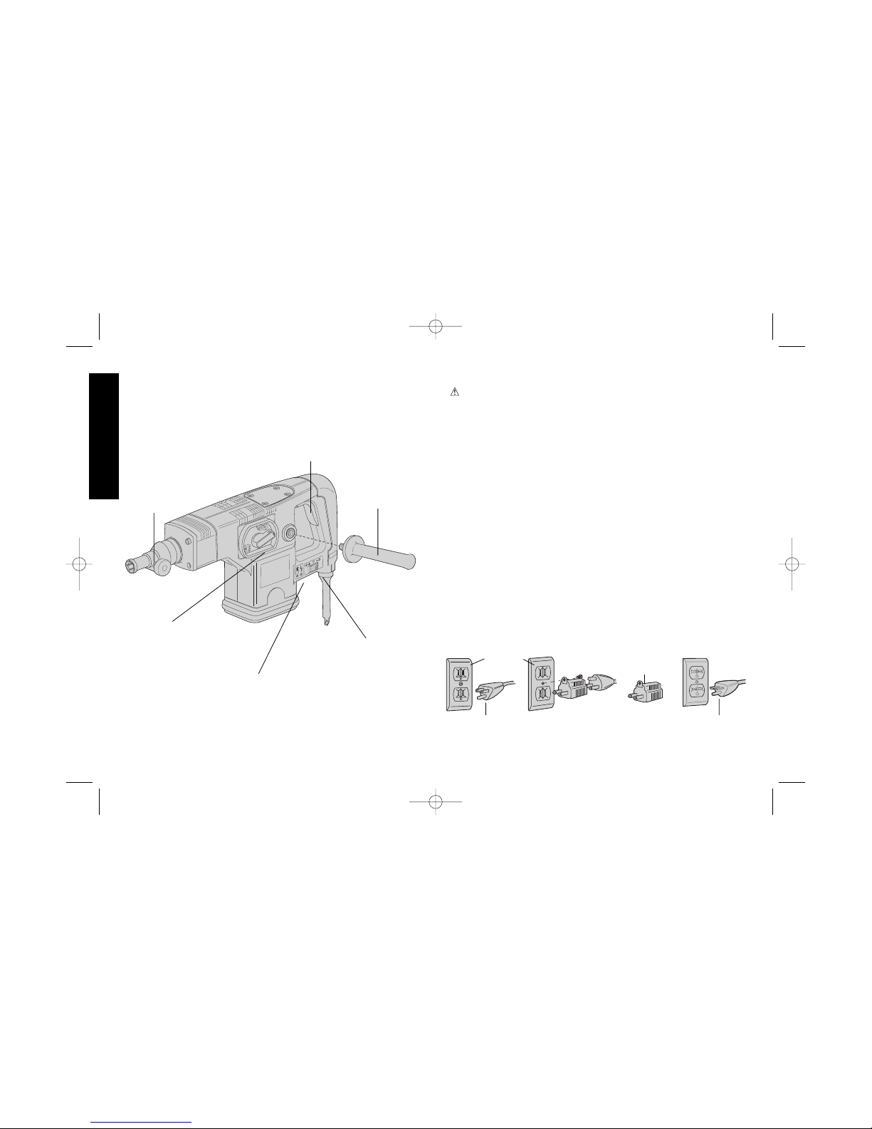
Grounding Instructions
This tool should be grounded while in use to protect the operator from
electric shock. The tool is equipped with a 3-conductor cord and 3prong grounding type plug to fit the proper grounding type receptacle.
The green (or green and yellow) conductor in the cord is the
grounding wire. Never connect the green (or green and yellow) wire
to a live terminal. If your unit is intended for use on less than 150 V, it
has a plug that looks like that shown in sketch A. If it is for use on
150 to 250 V, it has a plug that looks like that shown in sketch D. An
adapter, sketches B and C, is available for connecting sketch A type
plugs to 2-prong receptacles. The green-colored rigid ear, lug, or the
like, extending from the adapter must be connected to a permanent
ground, such as a properly grounded outlet box. No adapter is
available for a plug as shown in sketch D. ADAPTER SHOWN IN
FIGURES B and C IS NOT FOR USE IN CANADA.
English
IF YOU HAVE ANY QUESTIONS OR COMMENTS ABOUT THIS
OR ANY D
EWALT TOOL, CALL US TOLL FREE AT:
1-800-4-DEWALT (1-800-433-9258)
ON/OFF SWITCH
SPEED AND IMPACT
CONTROL DIAL (DW541,
DW532, DW533, DW545)
SERVICE AND POWERS INDICATORS
(DW541, DW532, DW533, DW540, DW545)
TOOL HOLDER
SIDE HANDLE
MODE SELECTOR
(ALL UNITS
EXCEPT DW530)
AB CD
GROUNDING PIN
GROUNDED
OUTLET
BOX
GROUNDING
MEANS
GROUNDING PIN
ADAPTER
154728-01 rev 9/10/02 2:23 PM Page 4
Page 4

Safety Instructions For All Tools
• KEEP WORK AREA CLEAN. Cluttered areas and benches invite
injuries.
• CONSIDER WORK AREA ENVIRONMENT. Don’t expose power
tools to rain. Don’t use power tools in damp or wet locations. Keep
work area well lit. Do not use tool in presence of flammable liquids
or gases.
• GUARD AGAINST ELECTRIC SHOCK. Prevent body contact with
grounded surfaces. For example; pipes, radiators, ranges, and
refrigerator enclosures.
• KEEP CHILDREN AWAY. Do not let visitors contact tool or
extension cord. All visitors should be kept away from work area.
• STORE IDLE TOOLS. When not in use, tools should be stored in
dry, and high or locked-up place — out of reach of children.
• DON’T FORCE TOOL. It will do the job better and safer at the rate
for which it was intended.
• USE RIGHT TOOL. Don’t force small tool or attachment to do the
job of a heavy-duty tool. Don’t use tool for purpose not intended.
• DRESS PROPERLY. Do not wear loose clothing or jewelry. They
can be caught in moving parts. Rubber gloves and non-skid
footwear are recommended when working outdoors. Wear
protective hair covering to contain long hair.
• USE SAFETY GLASSES. Also use face or dust mask if operation
is dusty.
• DON’T ABUSE CORD. Never carry tool by cord or yank it to
disconnect from receptacle. Keep cord from heat, oil, and sharp
edges.
• SECURE WORK. Use clamps or a vise to hold work. It’s safer than
using your hand and it frees both hands to operate tool.
• DON’T OVERREACH. Keep proper footing and balance at all
times.
• MAINTAIN TOOLS WITH CARE. Keep tools sharp and clean for
better and safer performance. Follow instructions for lubricating
and changing accessories. Inspect tool cords periodically and if
damaged, have repaired by authorized service facility. Inspect
extension cords periodically and replace if damaged. Keep handles
dry, clean, and free from oil and grease.
• DISCONNECT OR LOCK OFF TOOLS when not in use, before
servicing, and when changing accessories, such as blades, bits,
cutters.
• REMOVE ADJUSTING KEYS AND WRENCHES. Form habit of
checking to see that keys and adjusting wrenches are removed
from tool before turning it on.
• AVOID UNINTENTIONAL STARTING. Don’t carry tool with finger
on switch. Be sure switch is off when plugging in.
• EXTENSION CORDS. Make sure your extension cord is in good
condition. When using an extension cord, be sure to use one heavy
enough to carry the current your product will draw. An undersized
cord will cause a drop in line voltage resulting in loss of power and
overheating. The following table shows the correct size to use
depending on cord length and nameplate ampere rating. If in
doubt, use the next heavier gage. The smaller the gage number,
the heavier the cord.
Minimum Gage for Cord Sets
Volts Total Length of Cord in Feet
120V 0-25 26-50 51-100 101-150
240V 0-50 51-100 101-200 201-300
Ampere Rating
More Not more AWG
Than Than
0-6 18161614
6 - 10 18 16 14 12
10-1216161412
12 - 16 14 12 Not Recommended
• OUTDOOR USE EXTENSION CORDS. When tool is used
outdoors, use only extension cords intended for use outdoors and
so marked.
• STAY ALERT. Watch what you are doing. Use common sense. Do
1
English
154728-01 rev 9/10/02 2:23 PM Page 1
Page 5
2
not operate tool when you are tired.
• CHECK DAMAGED PARTS. Before further use of the tool, a guard
or other part that is damaged should be carefully checked to
determine that it will operate properly and perform its intended
function. Check for alignment of moving parts, binding of moving
parts, breakage of parts, mounting, and any other conditions that
may affect its operation. A guard or other part that is damaged
should be properly repaired or replaced by an authorized service
center unless otherwise indicated elsewhere in this instruction
manual. Have defective switches replaced by authorized service
center. Do not use tool if switch does not turn it on and off.
Additional Safety Instructions for Rotary
Hammers
• WEAR SAFETY GOGGLES or other eye protection.
• WEAR EAR PROTECTORS when hammering for extended
periods.
• ALWAYS USE THE SIDE HANDLE supplied with the tool. Keep a
firm grip on the hammer when it is operating.
• DON’T OVERREACH. Maintain a firm, balanced working stance.
When necessary, use only properly positioned, safe platforms,
ladders and scaffolds, to do the job safely.
• Hammer bits and tools get hot in operation. Wear gloves when
touching them.
• CAUTION: When drilling or driving into walls, floors or wherever
“live” electrical wires may be encountered, DO NOT TOUCH ANY
FRONT METAL PARTS OF THE TOOL! Hold the tool only by the
plastic handle to prevent shock if you drill or drive into a “live” wire.
SAVE THESE INSTRUCTIONS FOR
FUTURE USE
English
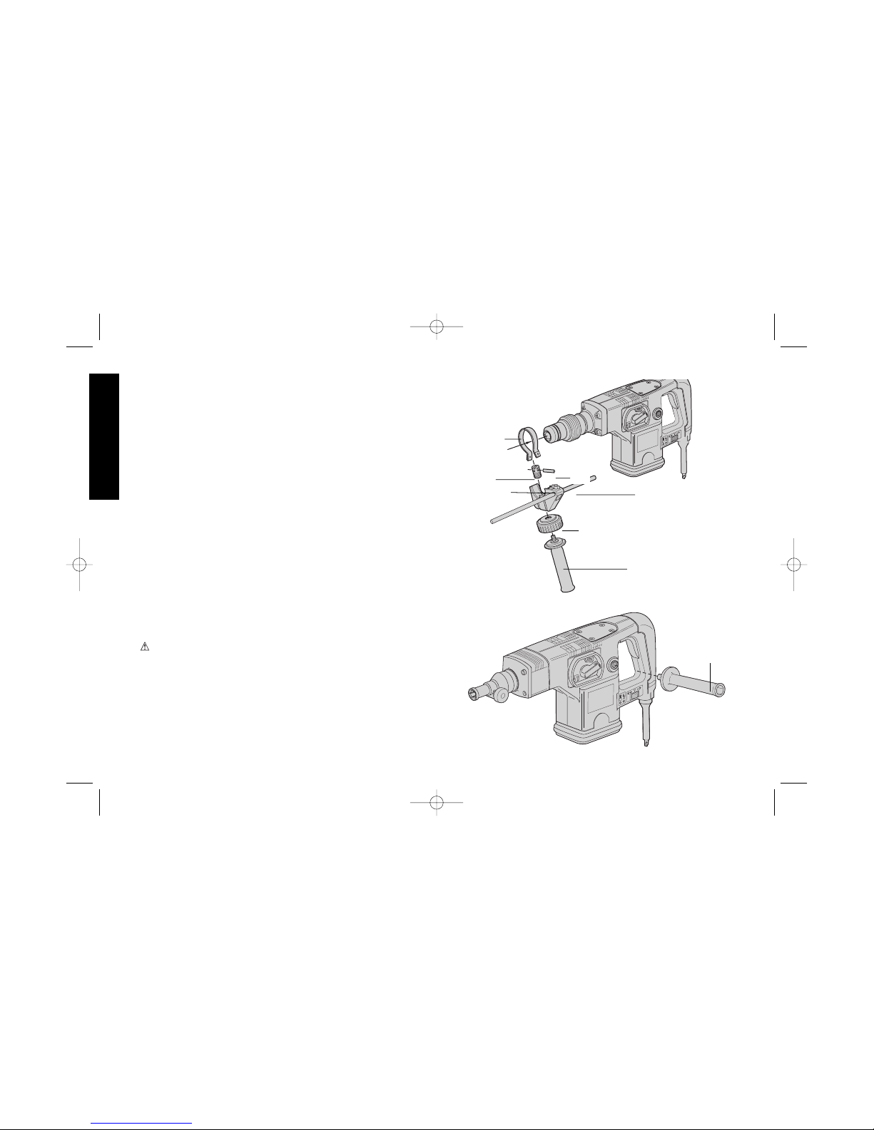
FIG. 1
FIG. 2
STEEL RING
BUSH
PIN
DEPTH ROD
CLAMP NUT
CLAMP KNOB
SIDE HANDLE
SIDE HANDLE
154728-01 rev 9/10/02 2:23 PM Page 2
Page 6
Motor
Your tool is powered by a D
EWALT built motor. Be sure your power
supply agrees with nameplate marking.
Voltage decrease of more than 10% will cause loss of power and
overheating. All D
EWALT tools are factory tested; if this tool does not
operate, check the power supply.
Side Handle and Depth Rod
For operating convenience, the side handle can be installed in front
or rear positions. Always operate the tool with the side handle
properly assembled.
TO MOUNT IN FRONT POSITION (FIG. 1)
1. Unscrew the side handle and disassemble the side handle clamp.
2. Snap the steel ring over the collar behind the tool holder. Squeeze
both ends together, mount the bush and insert the pin.
3. Place the side handle clamp and screw on the clamp knob. Do not
tighten.
4. Insert adjustable depth rod into hole.
5. Screw the side handle into the clamp knob and tighten it.
6. Rotate the side handle mounting assembly to the desired position.
For drilling horizontally with a heavy drill bit, place the side handle
assembly at an angle of approximately 20˚ for optimum control.
7. Lock the side handle mounting assembly in place by tightening the
clamp knob.
TO MOUNT IN REAR POSITION (FIG. 2)
1. Unscrew the side handle and remove it from the front position.
Leave the side handle mounting assembly in front position so that
the depth adjustment rod can still be used.
2. Screw the side handle directly into one of the rear side handle
positions on either side of the tool.
3
English
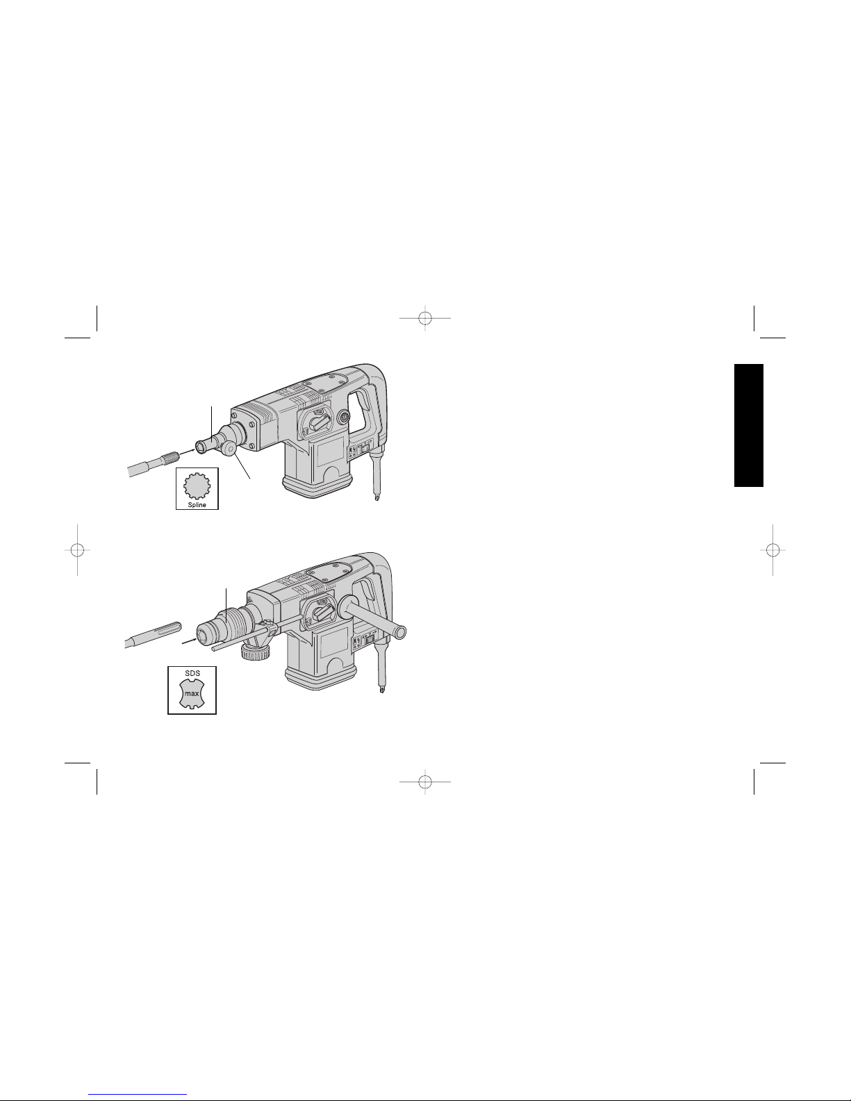
FIG. 3
FIG. 4
TOOL
HOLDER
RETAINING
PIN BUTTON
LOCKING
SLEEVE
154728-01 rev 9/10/02 2:23 PM Page 3
Page 7
4
TO ADJUST THE DEPTH ROD
1. Loosen clamp nut and insert bit into tool holder.
2. Push drill bit into a surface and adjust rod to desired depth of hole
(distance between bit tip and depth rod tip).
3. Tighten clamp nut.
NOTE: This adjustment can be made with or without side handle in
place.
Inserting and Removing Spline Drive
Accessories
FIG. 3: (DW531, DW530, DW532, DW533)
TURN OFF TOOL AND DISCONNECT FROM POWER SUPPLY.
1. Unlock the tool holder by pushing the retaining pin button and holding it
in.
2. Insert the bit shank into the tool holder as far as it will go.
3. Release the retaining pin button.
4. Pull on the bit to check if it is properly locked.
5. To remove a bit unlock the tool holder as described above.
Inserting and Removing SDS-max™
Accessories
FIG. 4: (DW541, DW540 AND DW545)
TURN OFF TOOL AND DISCONNECT FROM POWER SUPPLY.
1. Pull back the tool holder locking sleeve and insert the bit shank.
2. Turn the bit slightly until the sleeve snaps back in position.
3. Pull on the bit to check if it is properly locked. The hammering
function requires the bit to be able to move axially several
centimeters when locked in the tool holder.
4. To remove bit, pull back the tool holder locking sleeve and pull the
bit out of the tool holder.
English
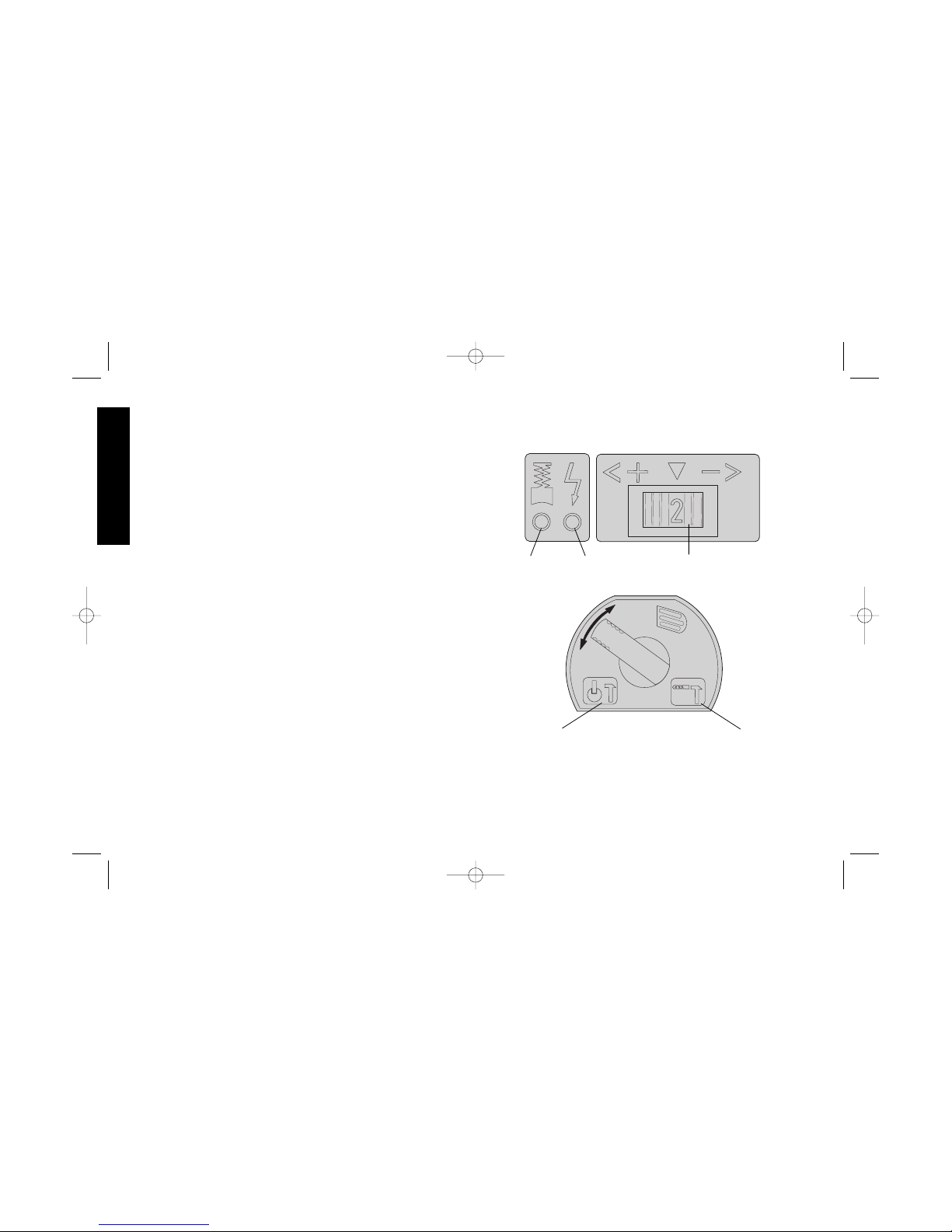
FIG. 5
FIG. 6
RED LED GREEN LED
ELECTRONIC SPEED /
IMPACT CONTROL
DIAL
HAMMER ONLY
WITH SPINDLE
LOCK
HAMMER DRILL
154728-01 rev 9/10/02 2:23 PM Page 4
Page 8

Soft Start Feature (DW541, DW532,
DW533, DW545)
The soft start feature allows you to build up speed slowly, thus
preventing the drill bit from walking off the intended hole position
when starting. The soft start feature also reduces the immediate
torque reaction transmitted to the gearing and the operator if the
hammer is started with the drill bit in an existing hole.
Torque Limiting Clutch
All rotary hammers are equipped with a torque limiting clutch that
reduces the maximum torque reaction transmitted to the operator in
the case of a jamming drill bit. This feature also prevents the gearing
and motor from stalling. The torque limiting clutch has been factory
set and cannot be adjusted.
Electronic Speed and Impact Control
(DW541, DW532, DW533, DW545)
(Fig. 5) The electronic speed and impact control allows the use of
smaller drill bits without the risk of bit breakage, drilling into light and
brittle materials without shattering, and optimal tool control for
precise chiseling. To set the control dial: Turn the dial to the desired
level. The higher the number, the greater the speed and impact
energy. With dial settings from “1” to “5” (full power) the tool is
extremely flexible and adaptable for many different applications. The
required setting depends on the bit size and hardness of material
being drilled.
Mode Selector
(Fig. 6) Your rotary hammer (all units except DW530) can be used in
two operating modes: Hammer drilling (simultaneous rotating and
impacting for all concrete and masonry drilling operations) and
Hammering only with spindle lock (impacting only- for light
chipping, chiseling, and demolition applications. The chisel can be
locked into 8 different positions.
NOTE: Also in this mode, the hammer can also be used as a lever to
free a jammed drill bit.
To select the required operating mode, rotate the selector lever
over the safety lock until it covers the symbol.
SERVICE AND POWER INDICATOR LEDS (DW541, DW532,
DW533, DW545)
(Fig. 5) The RED service indicator LED lights up when the carbon
brushes are nearly worn out to indicate that the tool needs servicing.
After approximately 8 hours of use the motor will automatically be
shut off. Take the tool to a D
EWALT service location for routine
inspection and maintenance.
The GREEN power-ON indicator LED lights up when the tool is
switched ON. If the indicator LED is lit but the tool does not start, this
indicates a motor related problem. If the indicator LED does not light
up and the tool does not start, this indicates an ON/OFF switch or
cord related problem.
DRILLING WITH A SOLID BIT
1. Set the speed and impact control dial (DW541, DW532, DW533,
DW545).
2. Set the model selector to the “hammer drilling” position (for all
units except DW530).
3. Insert the appropriate drill bit.
4. Fit and adjust the side handle.
5. If necessary, set the drilling depth rod.
5
English
154728-01 rev 9/10/02 2:23 PM Page 5
Page 9

6
6. Mark the spot where the hole is to be drilled.
7. Place the drill bit on the spot and press the ON/OFF switch.
8. Push with only enough force until hammer beats smoothly. The
hammer only needs enough pressure or force to engage the
mechanism. Pushing harder will not make the hammer drill faster.
9. To stop the tool, release the ON/OFF switch. Always turn the tool
OFF when work is finished and before unplugging.
DRILLING WITH A CORE BIT
1. Turn the speed and impact control dial to the maximum torque
position. (DW541, DW532, DW533 DW545)
2. Set the model selector to the “hammer drilling” position (for all
units except DW530).
3. Fit and adjust the side handle.
4. Assemble the centering bit and adapter shank into core bit.
5. Place the centering bit on the spot and press the ON/OFF switch.
NOTE: Some core drills require the removal of centering bit after
about 1 cm of penetration. If so, remove and continue drilling.
6. When drilling through a structure thicker than the depth of the core
bit, break away the round cylinder of concrete or core inside the bit
at regular intervals. To avoid unwanted breaking away of concrete
around the hole, first drill a hole the diameter of the centering bit
completely through the structure. Then drill the cored hole halfway
from each side.
7. To stop the tool, release the ON/OFF switch. Always turn the tool
OFF when work is finished and before unplugging.
CHIPPING AND CHISELING
1. Set the model selector to the “hammering only with spindle lock”
position on all models except DW530 in which it is not necessary.
2. Set the impact control dial to desired impact energy.
3. Insert the appropriate chisel and rotate it by hand to lock it into the
desired position. For spline units, use a 3/4” hex x 21/32” round
insert tool and for SDS Max models use SDS Max insert tools.
4. Fit and adjust the side handle.
5. Press the ON/OFF switch and start working.
6. Push with enough force to keep bit from bouncing only. Pushing
harder will not increase chipping speed.
7. To stop the tool, release the ON/OFF switch. Always turn the tool
OFF when work is finished and before unplugging.
Accessories
Recommended accessories for use with your tool are available at
extra cost from your distributor or local service center.
CAUTION: The use of any non-recommended accessory may be
hazardous.
Repairs
To assure product SAFETY and RELIABILITY, repairs, maintenance
and adjustment (including brush inspection and replacement) should
be performed by authorized service centers or other qualified service
organizations, always using identical replacement parts.
Full Warranty
DEWALT heavy duty industrial tools are warranted for one year from
date of purchase. We will repair, without charge, any defects due to
faulty materials or workmanship. For warranty repair information,
call 1-800-4-D
EWALT. This warranty does not apply to accessories
or damage caused where repairs have been made or attempted by
others. This warranty gives you specific legal rights and you may
have other rights which vary in certain states or provinces.
In addition to the warranty, D
EWALT tools are covered by our:
30 DAY NO RISK SATISFACTION GUARANTEE
If you are not completely satisfied with the performance of your
D
EWALT heavy duty industrial tool, simply return it to the participating
seller within 30 days for a full refund. Please return the complete unit,
transportation prepaid. Proof of purchase may be required.
English
154728-01 rev 9/10/02 2:23 PM Page 6
Page 10

7
Français
POUR TOUT RENSEIGNEMENT SUPPLÉMENTAIRE SUR CET
OUTIL OU TOUT AUTRE OUTIL DEWALT, COMPOSER SANS
FRAIS LE NUMÉRO:
1 800 4-DEWALT (1 800 433-9258)
Importantes mesures de sécurité
AVERTISSEMENT : Afin de réduire les risques d’incendie, de
secousses électriques ou de blessures lorsqu’on utilise des outils
électriques, il faut toujours respecter les mesures de sécurité
suivantes.
LIRE TOUTES LES DIRECTIVES.
Mise à la terre
L’outil devrait être mis à la terre lors de son utilisation afin de protéger
l’utilisateur contre les risques de secousses électriques. L’outil est
doté d’un cordon trifilaire et d’une fiche à trois broches de type mis à
la terre qui s’insère dans une prise mise à la terre. Le conducteur vert
(ou vert et jaune) du cordon est le fil de mise à la terre. Ne jamais
raccorder le fil vert (ou vert et jaune) à une borne sous tension.
Lorsque l’outil est conçu pour recevoir une alimentation de moins de
150 volts, il est doté d’une fiche semblable à celle illustrée à la figure
A. Lorsque l’outil est conçu pour recevoir une alimentation variant
entre 150 et 250 volts, il est doté d’une fiche semblable à celle
illustrée à la figure D. On peut se procurer un adaptateur (fig. B et C)
pour brancher une fiche semblable à celle de la figure A dans des
prises à deux orifices. Il faut alors relier la tige, la cosse ou le
dispositif similaire de couleur verte à une mise à la terre permanente
(comme une prise bien mise à la terre). Il n’y a pas d’adaptateur pour
AB CD
BROCHE DE PRISE
MISE À LA TERRE
BROCHE DE PRISE
MISE À LA TERRE
PRISE MISE
À LA TERRE
DISPOSITIF DE
MISE À LA TERRE
ADAPTATEUR
INTERRUPTEUR
RÉGULATEUR DE
VITESSE ET DE FORCE
DE FRAPPE (MODÈLES
DW541, DW532, DW533 ET
DW545)
TÉMOINS D’ENTRETIEN ET DE
FONCTIONNEMENT(MODÈLES
DW541, DW532, DW533, DW540 ET
DW545)
PORTE-EMBOUT
POIGNÉE
LATÉRALE
SÉLECTEUR DE MODE DE
FONCTIONNEMENT
(TOUS LES MODÈLES
SAUF LE MODELE DW530)
154728-01 rev 9/10/02 2:23 PM Page 7
Page 11

8
la fiche illustrée à la figure D. L’ADAPTATEUR ILLUSTRÉ AUX
FIGURES B ET C NE PEUT PAS ETRE UTILISÉ AU CANADA.
Utiliser seulement des cordons de rallonge trifilaires qui acceptent
des fiches à 3 broches et des prises à 3 orifices qui acceptent la fiche
de l’outil. Remplacer ou réparer les cordons endommagés.
Mesures de sécurité pour tous les outils
• BIEN DÉGAGER LA SURFACE DE TRAVAIL. Des surfaces et
des établis encombrés peuvent être la cause de blessures.
• TENIR COMPTE DU MILIEU DE TRAVAIL. Protéger les outils
électriques de la pluie. Ne pas s’en servir dans des endroits
humides ou mouillés. Bien éclairer la surface de travail. Ne pas se
servir de l’outil en présence de liquides ou de vapeurs
inflammables.
• SE PROTÉGER CONTRE LES SECOUSSES ÉLECTRIQUES.
Éviter tout contact avec des objets mis à la terre, comme des
tuyaux, radiateurs, cuisinières, réfrigérateurs et autres objets du
genre.
• ÉLOIGNER LES ENFANTS. Tous les visiteurs doivent être tenus
à l’écart de l’aire de travail et il faut les empêcher de toucher à
l’outil ou au cordon de rallonge.
• RANGER LES OUTILS INUTILISÉS. Il faut ranger les outils dans
un endroit sec, situé en hauteur ou fermé à clé, hors de la portée
des enfants.
• NE JAMAIS FORCER L’OUTIL. Afin d’obtenir un rendement sûr et
efficace, utiliser l’outil à son rendement nominal.
• UTILISER L’OUTIL APPROPRIÉ. Ne jamais exiger d’un petit outil
ou d’un accessoire le rendement d’un outil de fabrication plus
robuste. Se servir de l’outil selon l’usage prévu.
• PORTER DES VÊTEMENTS APPROPRIÉS. Éviter de porter des
vêtements amples et des bijoux qui peuvent être happés par les
pièces en mouvement. Porter des gants de caoutchouc et des
chaussures à semelle antidérapante pour travailler à l’extérieur.
Protéger la chevelure si elle est longue.
• PORTER DES LUNETTES DE SÉCURITÉ. Porter également un
masque respiratoire si le travail de coupe produit de la poussière.
• NE PAS MANIPULER LE CORDON DE FAÇON ABUSIVE. Ne
pas transporter l’outil par le cordon ni tirer sur ce dernier pour le
débrancher de la prise. Éloigner le cordon des sources de chaleur,
des flaques d’huile et des arêtes tranchantes.
• ASSUJETTIR LA PIÈCE. Immobiliser la pièce à l’aide de brides
ou d’un étau. On peut alors se servir des deux mains pour faire
fonctionner l’outil, ce qui est plus sûr.
• NE PAS DÉPASSER SA PORTÉE. Toujours demeurer dans une
position stable et garder son équilibre.
• PRENDRE SOIN DES OUTILS. Conserver les outils propres pour
qu’ils donnent un rendement supérieur et sûr. Suivre les directives
concernant la lubrification et le remplacement des accessoires.
Inspecter régulièrement le cordon de l’outil et le faire réparer au
besoin à un atelier d’entretien autorisé. Inspecter régulièrement les
cordons de rallonge et les remplacer lorsqu’ils sont endommagés.
S’assurer que les poignées sont toujours propres, sèches et libres
de toute tache d’huile ou de graisse.
• DÉBRANCHER OU VERROUILLER EN POSITION HORS
TENSION LES OUTILS NON UTILISÉS. Respecter cette mesure
lorsqu’on ne se sert pas de l’outil, ou qu’on doit le réparer ou en
changer un accessoire (comme une lame, un foret ou un couteau).
• ENLEVER LES CLÉS DE RÉGLAGE. Prendre l’habitude de
vérifier si les clés de réglage ont été retirées avant de faire
démarrer l’outil.
• ÉVITER LES DÉMARRAGES ACCIDENTELS. Ne pas laisser le
doigt sur l’interrupteur lorsqu’on transporte l’outil. S’assurer que
l’interrupteur est à la position hors circuit lorsqu’on branche l’outil.
• CORDONS DE RALLONGE. S’assurer que le cordon de rallonge
est en bon état. Lorsqu’on se sert d’un cordon de rallonge,
s’assurer qu’il est de calibre approprié pour la tension nécessaire
au fonctionnement de l’outil. L’utilisation d’un cordon de calibre
inférieur occasionne une baisse de tension entraînant une perte de
Français
154728-01 rev 9/10/02 2:23 PM Page 8
Page 12

puissance et la surchauffe. Le tableau suivant indique le calibre
approprié selon la longueur du cordon et les mentions de la plaque
signalétique de l’outil. En cas de doute, utiliser un cordon de calibre
supérieur. Le chiffre indiquant le calibre est inversement
proportionnel au calibre du cordon.
Calibre minimal des cordons de rallonge
Tension Longueur totale du cordon en pieds
120 V 0-25 26-50 51-100 101-150
240 V 0-50 51-100 101-200 201-300
Intensité (A)
Au Au Calibre moyen de fil (AWG)
moins plus
0-6 18161614
6 - 10 18 16 14 12
10-1216161412
12 - 16 14 12 Non recommandé
• CORDONS DE RALLONGE PRÉVUS POUR L’EXTÉRIEUR.
Lorsque l’outil est utilisé à l’extérieur, ne se servir que d’un cordon
de rallonge conçu pour l’extérieur et portant la mention appropriée.
• DEMEURER VIGILANT. Travailler avec vigilance et faire preuve
de bon sens. Ne pas se servir de l’outil lorsqu’on est fatigué.
• VÉRIFIER LES PIÈCES ENDOMMAGÉES. Avant de continuer à
utiliser l’outil, il faut vérifier si le protecteur ou toute autre pièce
endommagée remplit bien la fonction pour laquelle il a été prévu.
Vérifier l’alignement et les attaches des pièces mobiles, le degré
d’usure des pièces et leur montage, ainsi que tout autre facteur
susceptible de nuire au bon fonctionnement de l’outil. Faire réparer
ou remplacer tout protecteur ou toute autre pièce endommagée
dans un centre de service autorisé, sauf si le présent guide fait
mention d’un avis contraire. Confier le remplacement de tout
interrupteur défectueux à un centre de service autorisé. Ne jamais
se servir d’un outil dont l’interrupteur est défectueux.
Mesures de sécurité relatives aux
perceuses rotatives
• PORTER DES LUNETTES DE SÉCURITÉ ou tout autre
équipement protecteur pour les yeux.
• PORTER DES PROTEGE-TYMPANS lorsqu’on effectue des
travaux de perçage à percussion sur de longues périodes.
• TOUJOURS UTILISER LA POIGNÉE LATÉRALE fournie avec
l’outil. Saisir fermement l’outil en service.
• NE PAS DÉPASSER SA PORTÉE. Toujours demeurer dans une
position stable et garder son équilibre. Le cas échéant, se servir
uniquement de plates-formes, d’échelles et d’échafauds
sécuritaires afin de travailler en toute sécurité.
• Les outils et les accessoires deviennent chauds au toucher
lorsqu’on s’en sert. Porter des gants pour y toucher.
• MISE EN GARDE : Lorsqu’on perce ou qu’on visse dans les
murs, les planchers ou tout autre endroit où peuvent se trouver des
fils sous tension, NE PAS TOUCHER AUX COMPOSANTS
MÉTALLIQUES À L’AVANT DE L’OUTIL. Ne le saisir que par ses
poignées en plastique afin de se protéger des secousses
électriques que provoqueraient le contact du foret avec un fil sous
tension.
CONSERVER CES MESURES À TITRE
DE RÉFÉRENCE.
Moteur
Un moteur D
EWALT entraîne cet outil D
EWALT. Veiller à ce que la
tension d’alimentation soit conforme aux exigences de la plaque
signalétique de l’outil.
Une baisse de tension de plus de 10 p. 100 peut entraîner une perte
de puissance et la surchauffe. Tous les outils D
EWALT sont essayés
avant de quitter l’usine. Lorsque celui-ci refuse de fonctionner, vérifier
la source de courant électrique.
9
Français
154728-01 rev 9/10/02 2:23 PM Page 9
Page 13

10
Poignée latéral et jauge de profondeur
Par souci de commodité, la poignée latérale s’installe à l’avant ou à
l’arrière de l’outil. Se servir de l’outil seulement lorsque la poignée
latérale est bien installée.
INSTALLATION À L’AVANT (FIG. 1)
1. Dévisser la poignée latérale et en démonter le dispositif de
serrage.
2. Enclencher la bague en acier sur le collet derrière le porteembout. En serrer les extrémités l’une contre l’autre, installer la
douille et y insérer la tige.
3. Installer le dispositif de serrage de la poignée latérale et visser le
bouton de fixation en place. Ne pas serrer.
4. Insérer la jauge de profondeur réglable dans le trou.
5. Visser la poignée latérale dans le bouton de fixation et serrer
celui-ci.
6. Placer la poignée latérale à la position voulue. Pour percer à
l’horizontale à l’aide d’un gros foret, placer la poignée latérale à un
angle d’environ 20° afin d’en optimiser la maîtrise.
7. Verrouiller la poignée latérale en place en serrant le bouton de
fixation.
INSTALLATION À L’ARRIERE (FIG. 2)
1. Dévisser la poignée latérale et la retirer de la position avant.
Laisser le dispositif de montage de la poignée latérale dans la
position avant de façon à pouvoir se servir de la jauge de
profondeur.
2. Visser la poignée latérale directement dans l’une des positions à
l’arrière d’un côté ou de l’autre de l’outil.
RÉGLAGE DE LA JAUGE DE PROFONDEUR
1. Desserrer l’écrou de serrage et insérer le foret dans le porteembout.
2. Pousser le foret dans une surface et régler la jauge de profondeur
Français
FIG. 1
FIG. 2
BAGUE EN
ACIER
DOUILLE
TIGE
JAUGE DE
PROFONDEUR
ÉCROU DE
SERRAGE
BOUTON DE FIXATION
POIGNÉE
LATÉRALE
POIGNÉE
LATÉRALE
154728-01 rev 9/10/02 2:23 PM Page 10
Page 14

à la profondeur voulue pour le trou (la distance entre l’extrémité du
foret et celle de la jauge).
3. Resserrer l’écrou de serrage.
NOTE : Ce réglage peut se faire même si la poignée latérale n’est
pas en place.
Installation et retrait d’accessoires à tige
cannelée
FIG. 3 : (MODELES DW531, DW530, DW532 ET DW533)
METTRE L’OUTIL HORS TENSION ET LE DÉBRANCHER.
1. Déverrouiller le porte-embout en enfonçant le bouton de la tige de
retenue et en le maintenant enfoncé.
2. Insérer à fond la tige du foret.
3. Relâcher le bouton de la tige de retenue.
4. Tirer sur le foret pour s’assurer qu’il est bien bloqué.
5. Pour retirer le foret de l’outil, il suffit de déverrouiller le porteembout de la manière décrite précédemment.
Installation et retrait d’accessoires
SDS-max
FIG. 4 : (MODELES DW540, DW541 ET DW545)
METTRE L’OUTIL HORS TENSION ET LE DÉBRANCHER.
1. Tirer le manchon de verrouillage du porte-embout vers l’arrière et
insérer la tige du foret.
2. Faire tourner le foret légèrement jusqu’à ce que le manchon
s’enclenche en place.
3. Tirer sur le foret pour s’assurer qu’il est bien bloqué. En mode de
perçage à percussion, le foret doit pouvoir se déplacer de
plusieurs centimètres autour de son axe lorsqu’il est bloqué dans
le porte-embout.
11
Français
FIG. 3
FIG. 4
PORTE-EMBOUT
BOUTON DE
LA TIGE DE
RETENUE
MANCHON DE
VERROUILLAGE
154728-01 rev 9/10/02 2:23 PM Page 11
Page 15

12
4. Pour retirer le foret de l’outil, il suffit de tirer le manchon de
verrouillage du porte-embout vers l’arrière et de retirer le foret du
porte-embout.
Caractéristique de démarrage en douceur
(DW541, DW532, DW533 et DW545)
La caractéristique de démarrage en douceur permet à l’outil
d’accélérer graduellement afin d’éviter le déplacement du foret hors
de l’emplacement voulu pour le trou au moment du démarrage. Cette
caractéristique réduit également l’effet du couple immédiat transmis
aux engrenages et à l’utilisateur lorsque le foret se trouve dans un trou
existant au moment du démarrage du perçage à percussion.
Embrayage à limiteur de couple
Toutes les perceuses rotatives sont dotées d’un embrayage à limiteur
de couple afin de minimiser l’effet de couple maximal transmis à
l’utilisateur en cas de blocage du foret. Cette caractéristique prévient
également le calage du moteur et des engrenages. L’embrayage à
limiteur de couple est réglé en usine et on ne peut pas le régler.
Régulateur électronique de vitesse et de
force de frappe (Modèles DW541, DW532,
DW533 et DW545)
(FIG. 5) Le régulateur électronique de vitesse et de force de frappe
permet d’utiliser de petits forets sans risque de les briser, de percer
des matériaux légers et friables sans production d’éclats et de mieux
maîtriser l’outil afin de ciseler avec précision. Faire ce qui suit pour
régler le régulateur: Régler le cadran au niveau voulu. Plus le chiffre
est élevé, plus la vitesse et la force de frappe sont élevées. L’outil est
des pus souples et des plus adaptables pour de nombreuses
utilisations différentes grâce à des réglages variant de «1» à «5»
(pleine puissance). Le réglage varie en fonction de la dimension du
foret et de la dureté du matériau à percer.
Français
FIG. 5
FIG. 6
D.É.L.
ROUGE
D.É.L.
VERTE
RÉGULATEUR
ÉLECTRONIQUE DE VITESSE
ET DE FORCE DE FRAPPE
PERÇAGE À
PERCUSSION
SEULEMENT AVEC
ARBRE DE
VERROUILLAGE
PERCEUSE À
PERCUSSION
154728-01 rev 9/10/02 2:23 PM Page 12
Page 16

Sélecteur de mode de fonctionnement
(FIG. 6) La perceuse rotative (tous les modèles, sauf le
modèle DW530) peut servir en deux modes de fonctionnement : en
perçage à percussion (action simultanée de rotation et de frappe
pour percer le béton et la maçonnerie) et en perçage à percussion
avec l’arbre verrouillé (frappe seulement, pour les travaux légers de
burinage, de ciselage et de démolition). Le ciselage peut se faire en
8 positions différentes.
NOTE : Dans ce dernier mode, la perceuse peut également servir de
levier pour dégager un foret coincé.
Pour choisir le mode de fonctionnement voulu, faire tourner le
levier du sélecteur au-dessus du dispositif de verrouillage de sûreté
jusqu’à ce qu’il couvre le symbole.
TÉMOINS D’ENTRETIEN ET DE FONCTIONNEMENT À D.É.L.
(MODELES DW541, DW532, DW533 ET DW545)
(FIG. 5) Le témoin d’entretien à D.É.L. ROUGE s’allume lorsque les
balais sont presque usés afin d’indiquer qu’il faut les remplacer. Au
bout d’environ 8 heures d’utilisation après que le témoin se soit
allumé, le moteur s’arrête automatiquement. Confier l’outil au
personnel d’un centre de service D
EWALT pour lui faire subir une
inspection et un entretien de routine.
Le témoin de fonctionnement à D.É.L. VERTE s’allume lorsque l’outil
est mis sous tension. Lorsque le témoin s’allume mais que l’outil ne
démarre pas, cela signifie que le moteur est défectueux. Lorsque le
témoin ne s’allume pas et que l’outil ne démarre pas, cela signifie
que l’interrupteur ou le cordon est défectueux.
PERÇAGE À L’AIDE D’UN FORET PLEIN
1. Régler le régulateur de vitesse et de force de frappe (modèles
DW541, DW532, DW533 et DW545).
2. Régler le sélecteur de mode de fonctionnement au mode de
perçage à percussion (tous les modèles sauf le modèle DW530).
3. Insérer le foret approprié.
4. Régler la poignée latérale.
5. Le cas échéant, régler la jauge de profondeur.
6. Marquer l’emplacement du trou à percer.
7. Placer le foret sur l’emplacement et enfoncer l’interrupteur.
8. Pousser avec la force nécessaire jusqu’à ce que la frappe se
fasse en douceur. Il faut exercer seulement la pression nécessaire
pour engager le mécanisme. Une pression excessive n’accélère
pas le processus.
9. Pour arrêter l’outil, relâcher l’interrupteur. Toujours mettre l’outil
HORS TENSION à la fin des travaux et avant de le débrancher.
PERÇAGE À L’AIDE D’UN TRÉPAN CAROTTIER
1. Faire tourner le régulateur jusqu’à la position de couple maximal
(modèles DW541, DW532, DW533 et DW545).
2. Régler le sélecteur de mode de fonctionnement au mode de
perçage à percussion (tous les modèles sauf le modèle DW530).
3. Régler la poignée latérale.
4. Monter le foret de centrage et la tige de l’adaptateur sur le trépan
carottier.
5. Placer le foret de centrage sur la marque de l’emplacement et
enfoncer l’interrupteur.
NOTE : Dans le cas de certains trépans carottiers, il faut retirer le
foret de centrage lorsqu’il est enfoncé à environ 1 cm. Le cas
échéant, le retirer et continuer à percer.
6. Lorsqu’on perce une structure plus épaisse que la longueur du
trépan carottier, il faut briser à intervalles réguliers le cylindre de
béton qui se trouve dans le trépan. Afin d’éviter le bris non voulu
de béton autour du trou, il faut d’abord percer à travers toute la
structure un trou dont le diamètre correspond à celui du foret de
centrage. On perce ensuite la moitié du trou voulu de chaque côté
de la structure.
7. Pour arrêter l’outil, relâcher l’interrupteur. Toujours mettre l’outil
HORS TENSION à la fin des travaux et avant de le débrancher.
13
Français
154728-01 rev 9/10/02 2:23 PM Page 13
Page 17

14
BURINAGE ET CISELAGE
1. Choisir le mode de perçage à percussion avec l'arbre verrouillé
pour tous les modèles sauf le modèle DW530 pour lequel ce n'est
pas nécessaire.
2. Régler le régulateur à la force de frappe voulue.
3. Insérer le ciseau approprié et le faire tourner à la main jusqu'à ce
qu'il s'enclenche dans la position voulue. Dans le cas des forets à
tige cannelée, utiliser un outil d'insertion de 3/4 po hexagonal et
de 21/32 po rond. Dans les cas des modèles SDS Max, utiliser
un outil d'insertion SDS Max.
4. Régler la poignée latérale.
5. Enfoncer l'interrupteur et commencer à travailler.
6. User de la force nécessaire pour empêcher le ciseau de rebondir.
Une pression excessive n'accélère pas le processus.
7. Pour arrêter l'outil, relâcher l'interrupteur. Toujours mettre l'outil
HORS TENSION à la fin des travaux et avant de le débrancher.
Accessoires
Les accessoires recommandés pour l’outil sont vendus séparément
chez le distributeur ou au centre de service de la région.
MISE EN GARDE : L’utilisation de tout accessoire non
recommandé peut être dangereuse.
Reparations
Pour assurer la SÉCURITÉ D’EMPLOI et la FIABILITÉ de l’outil, n’en
confier la réparation, l’entretien et les rajustements (y compris
l’inspection des balais) qu’à un centre de service ou à un atelier
d’entretien autorisé n’utilisant que des pièces de rechange
identiques.
Garantie complète
Les outils industriels de service intensif D
EWALT sont garantis
pendant un an à partir de la date d’achat. Toute pièce d’un outil
D
EWALT qui s’avérait défectueuse en raison d’un vice de matière ou
de fabrication sera réparée sans frais. Pour obtenir de plus amples
renseignements sur les réparations couvertes para garantie,
composer le 1 (800) 4-D
EWALT. Il suffit de retourner l’outil complet à
un centre de service D
EWALT. La présente garantie ne couvre pas les
accessoires ni les avaries dues aux réparations tentées ou
effectuées par des tiers. Les modalités de la présente garantie
donnet des droits légaux spécifiques. L'utilisateur peut également
se prévaloir d'autres droits selon l'état ou la province qu'il habite.
En outre, la garantie suivante couvre les outils D
EWALT.
GARANTIE DE SATISFACTION DE 30 JOURS OU ARGENT
REMIS
Si, pour quelque raison que ce soit, l’outil ne donne pas entière
satisfaction, il suffit de le retourner où il a été acheté dans les 30 jours
suivant la date d’achat afin d’obtenir un remboursement intégral.
Prière de retourner l'outil complet port payé. Une preuve d'achat peut
être requise.
Français
154728-01 rev 9/10/02 2:23 PM Page 14
Page 18

Instrucciones importantes de seguridad
ADVERTENCIA: Es indispensable sujetarse a las precauciones
básicas de seguridad, con la finalidad de reducir el peligro de
incendio, choque eléctrico y lesiones personales, en todas las
ocasiones en que se utilicen herramientas eléctricas. Entre estas
precauciones se incluyen la siguientes:
LEA TODAS LAS INSTRUCCIONES
Instrucciones de aterrizaje
Esta herramienta debe conectarse a tierra para proteger al operador
de choques eléctricos. Esta unidad está equipada con un cordón
eléctrico de tres hilos aprobado y una clavija para aterrizaje de tres
patas para conectarse a la toma de corriente adecuada. El conductor
verde (o verde y amarillo) es el cable de tierra. Nunca conecte el
cable verde (o verde y amarillo) a una terminal viva. Si su unidad está
hecha para funcionar con menos de 150 volts, tiene una clavija
similar a la que se muestra en la figura A. Si es para usarse con
corriente de 150 a 250 volts, tiene una clavija como la que se
muestra en la figura D. Hay adaptadores, figuras B y C, para conectar
clavijas del tipo de la figura A a tomas de corriente para dos patas.
La oreja de color verde deberá conectarse a tierra permanente, tal
como una toma de corriente aterrizada adecuadamente. No hay
adaptadores para clavijas como la de la figura D. EL ADAPTADOR
MOSTRADO EN LAS FIGURAS B Y C NO ESTA HECHO PARA
USARSE EN CANADA.
15
Español
AB CD
PATA DE
CONEXION A
TIERRA
PATA DE
CONEXION A
TIERRA
TOMA DE
CORRIENTE
ATERRIZADA
MEDIO DE
ATERRIZAJE
ADAPTADOR
INTERRUPTOR DE
ENCENDIDO Y APAGADO
CONTROL DE VELOCIDAD
E IMPACTO (DW541,
DW532, DW533, DW545)
INDICADORES DE CORRIENTE Y
SERVICIO
(DW541, DW532, DW533, DW540,
DW545)
PORTA
HERRAMIENTA
MANGO
LATERAL
SELECTOR DE MODO
(TODAS LAS UNIDADES
EXCEPTO DW530)
Epecificaciones
(DW530, DW531, DW532, DW540, DW541)
Tensión de alimentación 120 V CA/CD
Potencia nominal: 1000 W
Consumo de corriente: 9,4 A
Frecuencia de operación: 50-60 Hz
(DW533, DW545)
Tensión de alimentación 120 V CA/CD
Potencia nominal: 1160 W
Consumo de corriente: 10,6 A
Frecuencia de operación: 50-60 Hz
154728-01 rev 9/10/02 2:23 PM Page 15
Page 19

16
Instrucciones de seguridad para todas las
herramientas
• CONSERVE LIMPIA LA ZONA DE TRABAJO. Las superficies y
los bancos con objetos acumulados en desorden propician los
accidentes.
• OTORGUE PRIORIDAD AL AMBIENTE DE TRABAJO. No deje
las herramientas eléctricas expuestas a la lluvia. No las utilice en
lugares inundados o mojados. Conserve bien iluminada la zona de
trabajo. No utilice la herramienta en presencia de líquidos o gases
inflamables.
• PROTEJASE CONTRA EL CHOQUE ELECTRICO. Evite el
contacto corporal con superficies aterrizadas, por ejemplo,
tuberías, radiadores, antenas y gabinetes de refrigeración.
• CONSERVE APARTADOS A LOS NIÑOS. No permita que los
visitantes toquen las herramientas o los cables de extensión. Los
visitantes deben estar alejados del área de trabajo.
• GUARDE LAS HERRAMIENTAS QUE NO EMPLEE. Las
herramientas que no se están utilizando deben guardarse en un
lugar seco y elevado o bajo llave, fuera del alcance de los niños.
• NO FUERCE LA HERRAMIENTA. Esta cumplirá su función mejor
y con más seguridad bajo las especificaciones para las que se
diseñó.
• EMPLEE LA HERRAMIENTA ADECUADA. No fuerce a una
herramienta pequeña o a sus dispositivos de montaje en un trabajo
de tipo pesado. No emplee la herramienta en una tarea para la que
no se diseñó.
• VISTASE DE LA MANERA ADECUADA. No tenga puestas ropas
o artículos de joyería flojos, pues podrían quedar atrapados por las
partes móviles de las herramientas. Se recomienda el empleo de
guantes de caucho y calzado antiderrapante cuando se trabaja al
aire libre. Cúbrase bien la cabeza para sujetarse el pelo si lo tiene
largo.
• COLOQUESE ANTEOJOS DE SEGURIDAD. Póngase también
una mascarilla contra el polvo si lo produce la operación que va a
efectuar.
• NO ABUSE DEL CABLE ELECTRICO. Nunca levante la
herramienta por el cordón ni tire de éste para desconectarlo del
enchufe. Apártelo del calor y los objetos calientes, las sustancias
grasosas y los bordes cortantes.
• SUJETE FIRMEMENTE LOS OBJETOS SOBRE LOS QUE
TRABAJE. Utilice prensas o tornillos de banco para sujetar bien
los objetos sobre los que va a trabajar. Esto ofrece mayor
seguridad que sujetar los objetos con la mano, y además deja
libres ambas manos para operar la herramienta.
• NO SE SOBREEXTIENDA. Conserve en todo momento bien
apoyados los pies, lo mismo que el equilibrio.
• CUIDE SUS HERRAMIENTAS. Conserve sus herramientas bien
afiladas y limpias para que funcionen mejor y con mayor
seguridad. Obedezca las instrucciones de lubricación y cambio
de accesorios. Inspeccione los cordones eléctricos con frecuencia
y, si los encuentra dañados, hágalos cambiar o reparar en un
centro de servicio autorizado. Revise también con frecuencia las
extensiones eléctricas y reemplácelas si están dañadas. Conserve
los mangos secos, limpios y libres de aceites y grasas.
• DESCONECTE LAS HERRAMIENTAS. Hágalo cuando no las
emplee, antes de darles servicio y cuando vaya a cambiarles
accesorios como seguetas, discos, brocas y otros dispositivos de
corte.
• RETIRE LAS LLAVES DE AJUSTE Y DE TUERCAS. Adquiera
el hábito de asegurarse de que se han retirado las llaves de ajuste
de la herramienta antes de accionarla.
• EVITE QUE LA HERRAMIENTA SE ACCIONE
ACCIDENTALMENTE. Nunca sostenga una herramienta con el
dedo en el interruptor si se encuentra conectada a la corriente
eléctrica. Asegúrese que el interruptor está en la posición de
“apagado” antes de conectarla.
• CABLES DE EXTENSION. Asegúrese que su extensión esté en
buenas condiciones. Cuando utilice un cordón de extensión,
asegúrese de emplear uno con el calibre suficiente para soportar
Español
154728-01 rev 9/10/02 2:23 PM Page 16
Page 20

la corriente necesaria para su producto. Una extensión con calibre
menor al necesario causará una caída en el voltaje de la línea,
resultando en pérdida de potencia y sobre calentamiento. El
cuadro siguiente muestra los calibres correctos para usarse de
acuerdo con la longitud de la extensión y el amperaje especificado.
Si tiene dudas, utilice el calibre siguiente, más pesado. Cuanto
más pequeño el número de calibre del alambre, mayor la
capacidad del cable.
Calibre mínimo para cordones de extensión
Volts Longitud total del cordón en metros
120V 0-7.62 7.63-15.24 15.25-30.48 30.49-45.72
240V 0-15.24 15.25-30.48 30.49-60.96 60.97-91.44
AMPERAJE
Más No más Calbre del cordón
de de
0-6 18 16 16 14
6 - 10 18 16 14 12
10 - 12 16 16 14 12
12 - 16 14 12 No Recomendado
• EXTENSIONES PARA TRABAJOS A LA INTEMPERIE. Cuando
trabaje a la intemperie, utilice siempre cordones de extensión
diseñados exclusivamente para esta finalidad y marcados así.
• NO SE DISTRAIGA. Concéntrese en lo que está haciendo.
Recurra al sentido común. No opere ninguna herramienta si se
encuentra fatigado.
• VERIFIQUE LAS PARTES DAÑADAS. Antes de seguir
empleando cualquier herramienta, es indispensable verificar con
mucho cuidado que las guardas u otras partes dañadas puedan
operar de la manera adecuada para cumplir con su función.
Verifique la alineación de las partes móviles, la firmeza con que
deben encontrarse sujetas en sus montaduras, las partes rotas,
las propias montaduras y cualesquiera otros DETALLES que
pudieran afectar a la operación de la herramienta. Las guardas y
las otras partes que se encuentren dañadas deberán repararse
bien o cambiarse en un centro de servicio autorizado, a menos
que se diga otra cosa en el manual del usuario. Haga que se
cambien los interruptores dañados en un centro de servicio
autorizado. No emplee ninguna herramienta que tenga inutilizado
o estropeado el interruptor.
Instrucciones adicionales de seguridad
para rotomartillos
• UTILICE ANTEOJOS DE SEGURIDAD u otro tipo de protección
para los ojos.
• UTILICE PROTECTORES PARA LOS OIDOS cuando taladre por
periodos prolongados.
• EMPLEE SIEMPRE EL MANGO LATERAL que se le suministró
con la herramienta. Sujete bien la herramienta cuando esté en
operación.
• NO SE EXTIENDA MÁS ALLÁ DE SU PUNTO DE EQUILIBRIO.
Conserve una postura balanceada y firme. Utilice plataformas o
escaleras únicamente cuando sea necesario, para realizar el
trabajo de manera segura.
• Las brocas y otras herramientas de corte se calientan con la
operación. Utilice guantes cuando las toque.
• PRECAUCION: Cuando taladre o atornille en muros, suelos o
cualquier otro sitio en el que puedan encontrarse cables eléctricos
“vivos”, ¡NO TOQUE EL BROQUERO NI. CUALQUIER OTRA
PARTA METALICA FRONTAL DEL TALADRO! Sostenga el taladro
por las superficies aislantes para prevenir las descargas eléctricas
en el caso de hacer contacto con un cable “vivo”.
CONSERVE ESTAS INSTRUCCIONES PARA
REFERENCIAS FUTURAS
Motor
Se herramienta funciona con un motor D
EWALT integrado.
Asegúrese que la alimentación de corriente concuerde con la
marcada en la placa de identificación de la herramienta.
17
Español
154728-01 rev 9/10/02 2:23 PM Page 17
Page 21

18
Disminuciones en el voltaje mayores al 10% causarán pérdida de
potencia y sobre calentamiento. Todas las herramientas se prueban
en la fábrica, si esta herramienta no funciona, verifique la toma de
corriente.
Mango lateral y varilla de profundidad
Para mayor comodidad durante su operación, se puede instalar el
mango lateral en las posiciones delantera o trasera. Nunca opere la
herramienta sin el mango auxiliar instalado.
PARA MONTARLO EN LA POSICION FRONTAL (FIGURA 1)
1. Destornille el mango lateral y desarme el sujetador del mango
lateral.
2. Coloque el aro de acero sobre el collarín detrás del sujetador de
la herramienta. Una ambos extremos, instale el buje e inserte el
perno.
3. Coloque el sujetador del mango lateral y atorníllelo en la perilla.
No apriete.
4. Inserte la varilla de profundidad ajustable en el orificio.
5. Apriete el mango lateral a la perilla.
6. Gire el montaje del mango lateral hasta la posición que desee.
Para taladrar horizontalmente con una broca grande, coloque el
mango lateral a un ángulo aproximado de 20° para máximo
control.
7. Asegure el montaje del mango lateral apretando la perilla de
fijación.
PARA MONTARLO EN LA POSICION TRASERA (FIGURA 2)
1. Destornille el mango lateral y retírelo de la posición frontal. Deje
el montaje del mango en la posición delantera para poder seguir
utilizando la varilla de profundidad.
2. Atornille el mango lateral directamente en una de las posiciones
traseras a cualquiera de los lados de la herramienta.
Español
FIG. 1
FIG. 2
ARO DE
ACERO
BUJE
PERNO
VARILLA DE
PROFUNDIDAD
TUERCA DE
SUJECION
PERILLA DE FIJACION
MANGO
LATERAL
MANGO
LATERAL
154728-01 rev 9/10/02 2:23 PM Page 18
Page 22

PARA AJUSTAR LA VARILLA DE PROFUNDIDAD
1. Afloje la tuerca de seguridad e inserte la broca en el broquero.
2. Empuje la broca en una superficie y ajuste la varilla a la
profundidad que desee (la distancia será la que quede entre la
punta de la broca y la punta de la varilla de profundidad).
3. Apriete la tuerca de seguridad.
NOTA: Este ajuste puede realizarse con el mango lateral en su sitio o
sin él.
Instalación y remoción de accesorios con
cuadro de mando ranurado
FIGURA 3: (DW531, DW530, DW532, DW533)
APAGUE LA HERRAMIENTA Y DESCONECTELA DE LA TOMA
DE CORRIENTE.
1. Quite el seguro al broquero oprimiendo el botón del perno retén y
conservándolo oprimido.
2. Inserte el vástago de la broca en el broquero tanto como sea
posible.
3. Suelte el botón del perno retén.
4. Tire de la broca para verificar que esté asegurada
apropiadamente.
5. Para quitar una broca, quite el seguro del broquero como se
describe anteriormente.
Instalación y remoción de accesorios SDSMax
FIGURA 4: (DW540, DW541 Y DW545)
APAGUE LA HERRAMIENTA Y DESCONECTELA DE LA TOMA
DE CORRIENTE.
1. Tire hacia atrás del mango de seguridad del broquero e inserte el
vástago del accesorio.
19
Español
FIG. 3
FIG. 4
PORTA
HERRAMIENTA
BOTON DEL
PERNO
RETEN
MANGO DE
SEGURIDAD
154728-01 rev 9/10/02 2:23 PM Page 19
Page 23

20
2. Gire ligeramente la broca hasta que el mango de seguridad se
devuelva a su posición natural.
3. Tire de la broca para verificar que esté asegurada
apropiadamente. La función de martillo requiere que la broca
pueda moverse de manera axial varios centímetros cuando esté
asegurada en el broquero.
4. Para sacar el accesorio, tire hacia atrás del mango de seguridad
del broquero y saque la broca del broquero.
Encendido suave (DW541, DW532, DW533,
DW545)
La característica de encendido suave le permite incrementar la
velocidad lentamente, evitando por consiguiente que la broca se
deslice de la posición en que se pretende iniciar un barreno. Esta
característica reduce también la reacción inmediata de torque
transmitido a los engranes y al operador si el rotomartillo se enciende
con la broca dentro de una barreno preexistente.
Embrague de par limitado
Todos los rotomartillos están equipados con un embrague de par
limitado que reduce la reacción máxima de torque transmitida al
operador en caso de que una broca se atasque. esta característica
también evita que el motor y los engranes se atasquen. El embrague
de par limitado se ajusta en la fábrica y no se puede alterar.
Control electrónico de velocidad e impact
(DW541, DW532, DW533, DW545)
(FIGURA 5) El control electrónico de velocidad e impacto permite el
uso de brocas más pequeñas evitando el riesgo de fractura, perforar
materiales ligeros y quebradizos sin astillar, y un control óptimo del
torque para cincelar con precisión. Para ajustar la perilla de
control: Gire la perilla al nivel deseado. Mientras mayor sea el
Español
FIG. 5
FIG. 6
LED
ROJO
LED
VERDE
CONTROL ELECTRONICO
DE VELOCIDAD E
IMPACTO
MARTILLO CON
SEGURO EN LA
FLECHA
ROTOMARTILLO
154728-01 rev 9/10/02 2:23 PM Page 20
Page 24

número, mayores serán la velocidad y el impacto. Con las posiciones
1 a 5 (máximo poder) de la perilla, la herramienta es
extremadamente flexible y adaptable a diversas aplicaciones. El
ajuste requerido depende del tamaño de la broca y de la dureza del
material que se piense barrenar.
Selector de modo
(FIGURA 6) Su rotomartillo (todas las unidades excepto el DW530)
puede utilizarse en dos modos de operación: Rotomartillo (rotación
e impacto simultáneos para todas las operaciones de perforación de
concreto y mampostería) y Acción de martillo con el seguro de la
flecha (solamente impacto- para aplicaciones ligeras de astillado,
cincelado y demolición). El cincel se puede asegurar en 8 posiciones
diferentes.
NOTA: En este modo, el rotomartillo puede utilizarse también como
palanca para liberar una broca atascada.
Para seleccionar el modo de operación gire el selector que se
encuentra sobre el seguro hasta que cubra el símbolo deseado.
LEDs INDICADORES DE SERVICIO Y ALIMENTACION (DW541,
DW532, DW533, DW545)
(FIGURA 5) El LED ROJO de indicación de servicio se enciende
cuando los carbones están cerca de desgastarse por completo para
indicar que la herramienta requiere servicio. Después de
aproximadamente 8 horas de uso, el motor se apagará
automáticamente. Lleve la herramienta a un centro de servicio
D
EWALT para una inspección de rutina y mantenimiento.
El LED VERDE de indicación de alimentación se enciende al
encender la unidad. Si el LED se enciende pero la herramienta no
arranca, se indica un problema relacionado con el motor. Si el LED
no enciende y la herramienta no arranca, se indica un problema
relacionado con el interruptor o el cable.
TALADRADO CON UNA BROCA SOLIDA
1. Ajuste la perilla de control de velocidad e impacto (DW541,
DW532, DW533, DW545).
2. Coloque el selector de modo en la posición de rotomartillo (para
todas las unidades excepto el DW530).
3. Coloque la broca apropiada.
4. Coloque y ajuste el mango lateral.
5. Ajuste la varilla de profundidad en caso necesario.
6. Marque el punto donde hará el barreno.
7. Coloque la broca en el punto y oprima el interruptor.
8. Empuje con fuerza suficiente hasta que el rotomartillo golpee
suavemente. El rotomartillo solamente necesita presión o fuerza
suficientes para activar el mecanismo. Empujar con más fuerza
no hará que el rotomartillo perfore más rápidamente.
9. Para detener la herramienta, suelte el interruptor. Siempre
apague el interruptor al terminar el trabajo y antes de desconectar
el rotomartillo.
TALADRADO CON BROCAS TUBULARES
1. Gire el control de velocidad e impacto a la posición de torque
máximo (DW541, DW532, DW533, DW545).
2. Coloque el selector de modo en la posición de rotomartillo (para
todas las unidades excepto el DW545).
3. Coloque y ajuste el mango lateral.
4. Ensamble el centro y el adaptador de vástago de la broca tubular.
5. Coloque el centro en el punto y oprima el interruptor.
NOTA: Algunas brocas tubulares requieren que se retire el centro
después de haber penetrado aproximadamente 1 cm. En tal caso,
quítelo y continúe perforando.
6. Cuando perfore a través de una estructura con espesor mayor a
la profundidad de la broca tubular, elimine el cilindro de concreto
que se forma dentro de la broca a intervalos regulares. Para evitar
21
Español
154728-01 rev 9/10/02 2:23 PM Page 21
Page 25

22
que el concreto se fracture alrededor del barreno, taladre primero
un orificio con el diámetro del centro que pase a través de la
estructura completa, y a continuación utilice la broca tubular
haciendo la mitad del barreno desde cada lado.
ASTILLADO Y CINCELADO
1. Coloque el selector de modo en la posición de “martillo con
seguro en la flecha” en todos los modelos excepto el DW530, en
el que no es necesario.
2. Ajuste el control de velocidad e impacto en el punto que desee.
3. Inserte el cincel apropiado y gírelo a mano para asegurarlo en la
posición deseada. Para unidades ranuradas, utilice un inserto de
3/4” hexagonal x 21/32” redondo (19 x 16,6 mm) y para los
modelos SDS Max utilice insertos SDS Max.
4. Coloque y ajuste el mango lateral.
5. Oprima el interruptor e inicie el trabajo.
6. Empuje con fuerza suficiente únicamente para evitar que rebote.
Empujar con más fuerza no aumentará la velocidad de astillado.
7. Para detener la herramienta, suelte el interruptor. Siempre
apague el interruptor al terminar el trabajo y antes de desconectar
el rotomartillo.
Accesorios
Dispone usted de los accesorios recomendados para su herramienta
con cargo adicional con su distribuidor local autorizado.
PRECAUCION: El empleo de cualquier accesorio no
recomendado puede ser peligroso.
Reparaciónes
Para garantizar la SEGURIDAD y la CONFIABILIDAD, deberán
hacerse reparaciones, mantenimiento y ajustes de esta herramienta
en los centros de servicio para herramientas industriales de D
EWALT.
u otras organizaciones calificadas. Estas organizaciones prestan
servicio a las herramientas DEWALT y emplean siempre refacciones
legítimas D
EWALT.
PARA REPARACION Y SERVICIO DE SUS HERRAMIENTAS
ELECTRICAS FAVOR DE DIRIGIRSE AL CENTRO DE SERVICIO MAS
CERCANO
CULIACAN
Av. Nicolas Bravo #1063 Sur (91 671) 242 10
GAUDALAJARA
Av. La Paz #1770 (91 3) 826 69 78.
LEON
Polara #32 (91 471) 314 56
MEXICO
Sonora #134 Hiprodromo Condesa 553-9979
MERIDA
Calle 63 #459 (91 99) 23 54 90
MONTERREY
Av. Francisco I. Madero Pte. 1820-A (91 83) 72 11 25
PUEBLA
17 Norte #2057 (91 22) 46 90 20
QUERETARO
Av. Madero 139 Pte. (91 42) 14 60 60
SAN LOUIS POTOSI
Pedro Moreno #408 Fracc. la Victoria (91 48) 14 25 67
TORREON
Blvd. Independencia, 96 pte. (91 17) 16 52 65
VERACRUZ
Prolongación Diaz Miron #4280 (91 29) 21 70 18
VILLAHERMOSA
Zaragoza #105 (91 93) 12 53 17
PARA OTRAS LOCALIDADES LLAME AL: 326 7100
Español
154728-01 rev 9/10/02 2:23 PM Page 22
Page 26

Garantía Completa
Las herramientas industriales D
EWALT están garantizadas durante un año a
partir de la fecha de compra. Repararemos, sin cargos, cualquier falla debida
a material o mano de obra defectuosos. Por favor regrese la unidad completa,
con el transporte pagado, a cualquier Centro de Servicio para Herramientas
Industriales de DEWALT o a las estaciones de servicio autorizado enlistadas
bajo "Herramientas Eléctricas" en la Sección Amarilla. Esta garantía no se
aplica a los accesorios ni a daños causados por reparaciones efectuadas
por terceras personas. Esta garantía le otorga derechos legales específicos,
y usted puede tener otros derechos que pueden variar de estado a estado.
En adición a la garantía, las herramientas D
EWALT están amparadas por
nuestra:
GARANTÍA DE SATISFACCIÓN SIN RIESGO POR 30 DÍAS
Si usted no se encuentra completamente satisfecho con el desempeño de
su herramienta industrial D
E
WALT, sencillamente devuélvala a los
vendedores participantes durante los primeros 30 días después de la fecha
de compra para que le efectúen un reembolso completo. Por favor regrese la
unidad completa, con el transporte pagado. Se puede requerir prueba de
compra.
23
Español
IMPORTADO: DEWALT S.A. DE C.V.
BOSQUES DE CIDROS ACCESO RADIATAS NO. 42
COL. BOSQUES DE LAS LOMAS.
05120 MÉXICO, D.F
TEL. 326-7100
Para servicio y ventas consulte
“HERRAMIENTAS ELECTRICAS”
en la sección amarilla.
154728-01 rev 9/10/02 2:23 PM Page 23
 Loading...